EP3133244B1 - Gekrümter filmkühldurchgang, der eine kühllufströmung in zwei richtungen verteilt - Google Patents
Gekrümter filmkühldurchgang, der eine kühllufströmung in zwei richtungen verteilt Download PDFInfo
- Publication number
- EP3133244B1 EP3133244B1 EP16184207.5A EP16184207A EP3133244B1 EP 3133244 B1 EP3133244 B1 EP 3133244B1 EP 16184207 A EP16184207 A EP 16184207A EP 3133244 B1 EP3133244 B1 EP 3133244B1
- Authority
- EP
- European Patent Office
- Prior art keywords
- component
- cooling airflow
- passage
- turbine
- film
- Prior art date
- Legal status (The legal status is an assumption and is not a legal conclusion. Google has not performed a legal analysis and makes no representation as to the accuracy of the status listed.)
- Active
Links
Images


Classifications
-
- F—MECHANICAL ENGINEERING; LIGHTING; HEATING; WEAPONS; BLASTING
- F02—COMBUSTION ENGINES; HOT-GAS OR COMBUSTION-PRODUCT ENGINE PLANTS
- F02C—GAS-TURBINE PLANTS; AIR INTAKES FOR JET-PROPULSION PLANTS; CONTROLLING FUEL SUPPLY IN AIR-BREATHING JET-PROPULSION PLANTS
- F02C7/00—Features, components parts, details or accessories, not provided for in, or of interest apart form groups F02C1/00 - F02C6/00; Air intakes for jet-propulsion plants
- F02C7/12—Cooling of plants
- F02C7/16—Cooling of plants characterised by cooling medium
- F02C7/18—Cooling of plants characterised by cooling medium the medium being gaseous, e.g. air
-
- F—MECHANICAL ENGINEERING; LIGHTING; HEATING; WEAPONS; BLASTING
- F01—MACHINES OR ENGINES IN GENERAL; ENGINE PLANTS IN GENERAL; STEAM ENGINES
- F01D—NON-POSITIVE DISPLACEMENT MACHINES OR ENGINES, e.g. STEAM TURBINES
- F01D5/00—Blades; Blade-carrying members; Heating, heat-insulating, cooling or antivibration means on the blades or the members
- F01D5/12—Blades
- F01D5/14—Form or construction
- F01D5/18—Hollow blades, i.e. blades with cooling or heating channels or cavities; Heating, heat-insulating or cooling means on blades
- F01D5/186—Film cooling
-
- F—MECHANICAL ENGINEERING; LIGHTING; HEATING; WEAPONS; BLASTING
- F05—INDEXING SCHEMES RELATING TO ENGINES OR PUMPS IN VARIOUS SUBCLASSES OF CLASSES F01-F04
- F05D—INDEXING SCHEME FOR ASPECTS RELATING TO NON-POSITIVE-DISPLACEMENT MACHINES OR ENGINES, GAS-TURBINES OR JET-PROPULSION PLANTS
- F05D2220/00—Application
- F05D2220/30—Application in turbines
- F05D2220/32—Application in turbines in gas turbines
-
- F—MECHANICAL ENGINEERING; LIGHTING; HEATING; WEAPONS; BLASTING
- F05—INDEXING SCHEMES RELATING TO ENGINES OR PUMPS IN VARIOUS SUBCLASSES OF CLASSES F01-F04
- F05D—INDEXING SCHEME FOR ASPECTS RELATING TO NON-POSITIVE-DISPLACEMENT MACHINES OR ENGINES, GAS-TURBINES OR JET-PROPULSION PLANTS
- F05D2260/00—Function
- F05D2260/20—Heat transfer, e.g. cooling
- F05D2260/202—Heat transfer, e.g. cooling by film cooling
Definitions
- This disclosure relates to gas turbine engines, and more particularly to film cooling of turbine components of gas turbine engines.
- Cooling air is often extracted from lower temperature portions of the turbomachine, for example, the compressor, and is utilized to cool the turbine components.
- One type of cooling utilized with this cooling flow is film cooling where the cooling air is delivered to an interior of the component then emitted over an external surface of the component.
- the cooling air is typically emitted through cooling holes that are machined into the part, and are circular in cross-section. Diffusion shapes are often added around the hole at the external surface.
- a film-cooled component for a gas turbine engine as claimed in claim 1.
- the first surface is an external surface of the component .
- the first radius is defined in a first plane oriented at a first angle ranging from 15 degrees to 90 degrees to the gas flow direction and the second radius is defined in a second plane oriented angularly offset from both the first plane and the streamwise direction.
- the angular offset is in the range of 0 to 50 degrees.
- a cooling airflow passage inlet has a circular cross-section.
- a cooling airflow passage outlet has a major axis with a lateral component perpendicular to the gas flow direction and a streamwise component parallel to the gas flow direction.
- elongation of the cooling airflow passage increases continuously with distance from the second surface.
- the component is a turbine vane.
- the component is formed via additive manufacturing.
- a gas turbine engine in another embodiment, includes a combustor and a turbine positioned in fluid communication with the combustor.
- the turbine has a plurality of turbine components, at least one turbine component being a film-cooled component as described above.
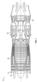
- FIG. 1 is a schematic illustration of a gas turbine engine 10.
- the gas turbine engine generally has a fan 12 through which ambient air is propelled in the direction of arrow 14, a compressor 16 for pressurizing the air received from the fan 12 and a combustor 18 wherein the compressed air is mixed with fuel and ignited for generating combustion gases.
- the gas turbine engine 10 further comprises a turbine section 20 for extracting energy from the combustion gases. Fuel is injected into the combustor 18 of the gas turbine engine 10 for mixing with the compressed air from the compressor 16 and ignition of the resultant mixture.
- the fan 12, compressor 16, combustor 18, and turbine 20 are typically all concentric about a common central longitudinal axis of the gas turbine engine 10.
- the gas turbine engine 10 may further comprise a low pressure compressor located in front of a high pressure compressor and a high pressure turbine located in front of a low pressure turbine.
- the compressor 16 may be a multistage compressor 16 that has a low-pressure compressor and a high-pressure compressor and the turbine 20 may be a multistage turbine 20 that has a high-pressure turbine and a low-pressure turbine.
- the low-pressure compressor is connected to the low-pressure turbine and the high pressure compressor is connected to the high-pressure turbine.
- the turbine 20 includes one or more sets, or stages, of fixed turbine vanes 22 and turbine rotors 24, each turbine rotor 24 including a plurality of turbine blades 26.
- the turbine vanes 22 and the turbine blades 26 define a gas path for gas flow 30 through the turbine.
- the turbine vanes 22 and the turbine blades 26 utilize a cooling airflow to maintain the turbine components within a desired temperature range.
- the cooling airflow may flow internal through the turbine components to cool the components internally, while in other embodiments, the cooling airflow is utilized to form a cooling film on external surfaces of the components.
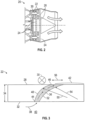
- FIG. 3 Shown in FIG. 3 is a partial cross-sectional view of an embodiment of a turbine component utilizing film cooling, for example, a turbine vane 22. While the embodiments herein are described with reference to turbine vane 22, it is to be appreciated that the present disclosure could be readily applied to other components such as turbine rotor 24, turbine blades 26, turbine case, combustor liners, blade outer air seals, or the like.
- the turbine vane 22 has an external surface 28 (a first surface) interactive with the gas flow 30 (shown into the paper in FIG. 3 ) through the turbine 20 and an internal surface 32 (a second surface) offset from the external surface 28 by a vane material thickness 34.
- the turbine vane 22 includes one or more cooling airflow passages 36 extending through the vane material thickness 34 from the internal surface 32 to the external surface 28.
- the cooling airflow passage 36 conveys a cooling airflow 38 from an internal passage 40 or component passage defined by the internal surface 32 and emits the cooling airflow 38 across the external surface 28 to form a cooling film 42 at the external surface 28 to thermally protect the external surface 28 from the gas flow 30.
- the turbine vane 22 is formed via additive manufacturing methods such as 3-D printing or material deposition to allow inclusion of the cooling airflow passage 36.
- the turbine vane 22 is formed via other methods such as casting, where the cooling airflow passage 36 may be cast in, or added after casting in secondary processing.
- the cooling airflow passage 36 includes a passage inlet 44 at the internal surface 32 and a passage outlet 46 at the external surface 28.
- the passage inlet 44 is circular, while the passage outlet 46 is non-circular, in some embodiments oval or elliptical in shape.
- the cooling airflow passage 36 diffuses the cooling airflow 38 by having an outlet area greater than an inlet area.
- the cooling airflow passage 36 as seen in the cross-section of FIG. 3 has an outboard surface 48 defined by an outboard surface radius 50 and an inboard surface 52 defined by an inboard surface radius 54.
- the inboard surface radius 54 is larger than the outboard surface radius 50, resulting in enlarging of the cooling airflow passage 36 in a lateral direction 56, substantially perpendicular to the gas flow 30, as the cooling airflow passage 36 extends through the material thickness 34 from the passage inlet 44 to the passage outlet 46.
- the outboard surface radius 50 is defined in an outboard surface radius plane 58 that is at an angle of between 15 and 90 degrees to the gas flow 30, while the inboard surface radius 54 is defined in an inboard surface radius plane 60, angularly offset from the outboard surface radius plane 58.
- the angular offset introduces diffusion of the cooling airflow passage 36 in a streamwise direction 62, substantially parallel to the gas flow 30.
- the degree of streamwise diffusion depends on the degree of angular offset of the inboard surface radius plane 60 relative to the outboard surface radius plane 58.
- the angular offset is in a range of 0 to 50 degrees.
- FIGs. 5A-5C the diffusion of the cooling airflow passage 36 is illustrated as the cooling airflow passage 36 progresses through the material thickness 34.
- the passage inlet 44 is illustrated.
- the passage inlet 44 is circular or near-circular with a major axis 64 perpendicular to the gas flow 30.
- FIG. 5B shown is a profile of the cooling airflow passage 36 at a point approximately midway through the material thickness 34. At this point, the cooling airflow passage 36 is elongated along the major axis 64, which now has a streamwise component, in a direction parallel to the gas flow.
- the passage outlet 46 is illustrated in FIG. 5C .
- the passage outlet 46 is further diffused relative to the cross-section of FIG. 5B , with the major axis 64 having a greater streamwise component.
- the cooling airflow passage curvilinearly diffuses in at least two directions relative to a local gas flow direction in the gas path.
- the cooling airflow passage 36 has both lateral and streamwise curvilinear diffusion through the material thickness 34 allowing for improved cooling film 42 attachment to the external surface 28 and improved cooling performance.
Landscapes
- Engineering & Computer Science (AREA)
- Mechanical Engineering (AREA)
- General Engineering & Computer Science (AREA)
- Chemical & Material Sciences (AREA)
- Combustion & Propulsion (AREA)
- Turbine Rotor Nozzle Sealing (AREA)
Claims (10)
- Filmgekühlte Komponente (22) für ein Gasturbinentriebwerk (10), umfassend:eine erste Fläche (28) der Komponente (22), die sich an einem Gasweg (30) eines Gasturbinentriebwerks (10) befindet;eine zweite Fläche (32) der Komponente (22), die einen inneren Komponentendurchgang (40) definiert; undeinen Kühlluftströmungsdurchgang (36), der sich von der zweiten Fläche (32) zu der ersten Fläche (28) erstreckt, um eine Kühlluftströmung (38) aus dem inneren Komponentendurchgang (40) zu leiten und die Kühlluftströmung (38) an der ersten Fläche (28) auszustoßen, wobei der Kühlluftströmungsdurchgang (36) einen Durchgangseinlass (44) an der zweiten Fläche (32) und einen Durchgangsauslass (46) an der ersten Fläche (28) aufweist, wobei der Durchgangsauslass (46) einen Flächeninhalt aufweist, der größer ist als der Flächeninhalt des Durchgangseinlasses (44), wobei eine seitliche Richtung senkrecht zu der lokalen Gasströmungsrichtung und eine Stromrichtung (62) parallel zu der lokalen Gasströmungsrichtung verläuft;dadurch gekennzeichnet, dass:der Kühlluftströmungsdurchgang (36) entlang einer Hauptachse (64) durch einen äußeren Flächenradius (50) und einen inneren Flächenradius (54) definiert ist, der seitlich von dem äußeren Flächenradius (50) versetzt ist, wobei der innere Flächenradius (54) größer ist als der äußere Flächenradius (50);der äußere Flächenradius (50) in einer ersten Ebene (58) mit einem ersten Winkel in einem Bereich von 15 Grad bis 90 Grad zu der Gasströmungsrichtung definiert ist;der innere Flächenradius (54) in einer zweiten Ebene (60) definiert ist, die winkelversetzt sowohl zu der ersten Ebene (58) als auch zu der Stromrichtung (62) ausgerichtet ist; und der Kühlluftströmungsdurchgang (36) die Kühlluftströmung (38) in mindestens zwei Richtungen relativ zu einer lokalen Gasströmungsrichtung in dem Gasweg verteilt.
- Filmgekühlte Komponente nach Anspruch 1, wobei die erste Fläche (28) eine Außenfläche der Komponente (22) ist.
- Filmgekühlte Komponente nach Anspruch 1, wobei der Winkelversatz in dem Bereich von 0 bis 50 Grad liegt.
- Filmgekühlte Komponente nach einem der vorhergehenden Ansprüche, wobei ein Kühlluftströmungsdurchgangseinlass (44) einen kreisförmigen Querschnitt aufweist.
- Filmgekühlte Komponente nach einem der vorhergehenden Ansprüche, wobei ein Kühlluftströmungsdurchgangsauslass (46) eine Hauptachse (64) mit einer seitlichen Komponente senkrecht zu der Gasströmungsrichtung und einer Stromkomponente parallel zu der Gasströmungsrichtung aufweist.
- Filmgekühlte Komponente nach einem der vorhergehenden Ansprüche, wobei die Verteilung des Kühlluftströmungsdurchgangs (36) mit zunehmender Entfernung von der zweiten Fläche (32) kontinuierlich zunimmt.
- Filmgekühlte Komponente nach einem der vorhergehenden Ansprüche, wobei die Komponente eine Turbinenleitschaufel (22) ist.
- Filmgekühlte Komponente nach einem der vorhergehenden Ansprüche, wobei die Komponente über additive Herstellung gebildet ist.
- Gasturbinentriebwerk (10), umfassend:eine Brennkammer (18); undeine Turbine (20), die in Fluidverbindung mit der Brennkammer (18) angeordnet ist, wobei die Turbine (20) eine Vielzahl von Turbinenkomponenten (22, 26) aufweist und mindestens eine Turbinenkomponente eine filmgekühlte Komponente (22) nach einem der vorhergehenden Ansprüche ist.
- Verfahren zum Filmkühlen einer Turbinenkomponente (22) eines Gasturbinentriebwerks (10), umfassend:Strömen einer Kühlluftströmung (38) in einen inneren Komponentendurchgang (40) der Turbinenkomponente (22);Leiten der Kühlluftströmung (38) durch einen Kühlluftströmungsdurchgang (36);Verteilen der Kühlluftströmung (38) in mindestens zwei Richtungen entlang des Kühlluftströmungsdurchgangs (36); undAusstoßen der Kühlluftströmung (38) an einer Gaswegfläche (28) der Komponente (22), um die Gaswegfläche (28) der Komponente (22) zu kühlen, wobei der Kühlluftströmungsdurchgang (36) einen Durchgangseinlass (44) und einen Durchgangsauslass (46) aufweist, wobei der Durchgangsauslass (46) einen Flächeninhalt aufweist, der größer ist als der Flächeninhalt eines Durchgangseinlasses (44), wobei eine seitliche Richtung senkrecht zu der lokalen Gasströmungsrichtung und eine Stromrichtung (62) parallel zu der lokalen Gasströmungsrichtung verläuft;dadurch gekennzeichnet, dass:der Kühlluftströmungsdurchgang (36) entlang einer Hauptachse (64) durch einen äußeren Flächenradius (50) und einen inneren Flächenradius (54) definiert ist, der seitlich von dem äußeren Flächenradius (50) versetzt ist, wobei der innere Flächenradius (54) größer ist als der äußere Flächenradius (50);der äußere Flächenradius (50) in einer ersten Ebene (58) mit einem ersten Winkel in einem Bereich von 15 Grad bis 90 Grad zu der Gasströmungsrichtung definiert ist;der innere Flächenradius (54) in einer zweiten Ebene (60) definiert ist, die winkelversetzt sowohl zu der ersten Ebene (58) als auch zu der Stromrichtung (62) ausgerichtet ist; und die Kühlluftströmung in mindestens zwei Richtungen relativ zu einer lokalen Gasströmungsrichtung in dem Gasweg verteilt wird.
Applications Claiming Priority (1)
| Application Number | Priority Date | Filing Date | Title |
|---|---|---|---|
| US14/827,773 US10626796B2 (en) | 2015-08-17 | 2015-08-17 | Film cooling passage with multidimensional diffusion |
Publications (2)
| Publication Number | Publication Date |
|---|---|
| EP3133244A1 EP3133244A1 (de) | 2017-02-22 |
| EP3133244B1 true EP3133244B1 (de) | 2025-01-08 |
Family
ID=56684559
Family Applications (1)
| Application Number | Title | Priority Date | Filing Date |
|---|---|---|---|
| EP16184207.5A Active EP3133244B1 (de) | 2015-08-17 | 2016-08-15 | Gekrümter filmkühldurchgang, der eine kühllufströmung in zwei richtungen verteilt |
Country Status (2)
| Country | Link |
|---|---|
| US (1) | US10626796B2 (de) |
| EP (1) | EP3133244B1 (de) |
Families Citing this family (1)
| Publication number | Priority date | Publication date | Assignee | Title |
|---|---|---|---|---|
| DE102019200985B4 (de) * | 2019-01-25 | 2023-12-07 | Rolls-Royce Deutschland Ltd & Co Kg | Triebwerksbauteil mit mindestens einem Kühlkanal und Herstellungsverfahren |
Family Cites Families (7)
| Publication number | Priority date | Publication date | Assignee | Title |
|---|---|---|---|---|
| US6368060B1 (en) * | 2000-05-23 | 2002-04-09 | General Electric Company | Shaped cooling hole for an airfoil |
| US8066484B1 (en) | 2007-11-19 | 2011-11-29 | Florida Turbine Technologies, Inc. | Film cooling hole for a turbine airfoil |
| US8092176B2 (en) | 2008-09-16 | 2012-01-10 | Siemens Energy, Inc. | Turbine airfoil cooling system with curved diffusion film cooling hole |
| US20120102959A1 (en) * | 2010-10-29 | 2012-05-03 | John Howard Starkweather | Substrate with shaped cooling holes and methods of manufacture |
| US8572983B2 (en) * | 2012-02-15 | 2013-11-05 | United Technologies Corporation | Gas turbine engine component with impingement and diffusive cooling |
| US9243502B2 (en) * | 2012-04-24 | 2016-01-26 | United Technologies Corporation | Airfoil cooling enhancement and method of making the same |
| US20160245094A1 (en) * | 2015-02-24 | 2016-08-25 | General Electric Company | Engine component |
-
2015
- 2015-08-17 US US14/827,773 patent/US10626796B2/en active Active
-
2016
- 2016-08-15 EP EP16184207.5A patent/EP3133244B1/de active Active
Also Published As
| Publication number | Publication date |
|---|---|
| US20170051673A1 (en) | 2017-02-23 |
| US10626796B2 (en) | 2020-04-21 |
| EP3133244A1 (de) | 2017-02-22 |
Similar Documents
| Publication | Publication Date | Title |
|---|---|---|
| US9982541B2 (en) | Gas turbine engine flow path member | |
| US10386069B2 (en) | Gas turbine engine wall | |
| US11313235B2 (en) | Engine component with film hole | |
| US9650900B2 (en) | Gas turbine engine components with film cooling holes having cylindrical to multi-lobe configurations | |
| US10443398B2 (en) | Turbine blade | |
| EP3061911A1 (de) | Motorbauteil | |
| US11773729B2 (en) | Component for a gas turbine engine with a film hole | |
| US20160251966A1 (en) | Engine component | |
| US20170101870A1 (en) | Cooling holes of turbine | |
| EP3034793B1 (de) | Gasturbinenmotorkomponente mit erhöhter kühlleistung | |
| CN106801623A (zh) | 涡轮叶片 | |
| US20190316473A1 (en) | Trailing edge cooling for a turbine blade | |
| US20180230811A1 (en) | Film cooling hole including offset diffuser portion | |
| US20100047078A1 (en) | Blade | |
| EP3133244B1 (de) | Gekrümter filmkühldurchgang, der eine kühllufströmung in zwei richtungen verteilt | |
| KR20240017741A (ko) | 플레넘을 통해 필름 냉각 홀에 결합된 리딩 에지 냉각 통로(들)가 있는 터빈 에어포일, 및 관련 방법 | |
| CN110344943B (zh) | 用于涡轮机械构件的冷却结构 | |
| US10677070B2 (en) | Blade platform gusset with internal cooling |
Legal Events
| Date | Code | Title | Description |
|---|---|---|---|
| PUAI | Public reference made under article 153(3) epc to a published international application that has entered the european phase |
Free format text: ORIGINAL CODE: 0009012 |
|
| STAA | Information on the status of an ep patent application or granted ep patent |
Free format text: STATUS: THE APPLICATION HAS BEEN PUBLISHED |
|
| AK | Designated contracting states |
Kind code of ref document: A1 Designated state(s): AL AT BE BG CH CY CZ DE DK EE ES FI FR GB GR HR HU IE IS IT LI LT LU LV MC MK MT NL NO PL PT RO RS SE SI SK SM TR |
|
| AX | Request for extension of the european patent |
Extension state: BA ME |
|
| STAA | Information on the status of an ep patent application or granted ep patent |
Free format text: STATUS: REQUEST FOR EXAMINATION WAS MADE |
|
| 17P | Request for examination filed |
Effective date: 20170822 |
|
| RBV | Designated contracting states (corrected) |
Designated state(s): AL AT BE BG CH CY CZ DE DK EE ES FI FR GB GR HR HU IE IS IT LI LT LU LV MC MK MT NL NO PL PT RO RS SE SI SK SM TR |
|
| RAP1 | Party data changed (applicant data changed or rights of an application transferred) |
Owner name: RAYTHEON TECHNOLOGIES CORPORATION |
|
| STAA | Information on the status of an ep patent application or granted ep patent |
Free format text: STATUS: EXAMINATION IS IN PROGRESS |
|
| 17Q | First examination report despatched |
Effective date: 20210406 |
|
| RAP3 | Party data changed (applicant data changed or rights of an application transferred) |
Owner name: RTX CORPORATION |
|
| GRAP | Despatch of communication of intention to grant a patent |
Free format text: ORIGINAL CODE: EPIDOSNIGR1 |
|
| STAA | Information on the status of an ep patent application or granted ep patent |
Free format text: STATUS: GRANT OF PATENT IS INTENDED |
|
| INTG | Intention to grant announced |
Effective date: 20240221 |
|
| GRAJ | Information related to disapproval of communication of intention to grant by the applicant or resumption of examination proceedings by the epo deleted |
Free format text: ORIGINAL CODE: EPIDOSDIGR1 |
|
| STAA | Information on the status of an ep patent application or granted ep patent |
Free format text: STATUS: EXAMINATION IS IN PROGRESS |
|
| INTC | Intention to grant announced (deleted) | ||
| GRAP | Despatch of communication of intention to grant a patent |
Free format text: ORIGINAL CODE: EPIDOSNIGR1 |
|
| STAA | Information on the status of an ep patent application or granted ep patent |
Free format text: STATUS: GRANT OF PATENT IS INTENDED |
|
| INTG | Intention to grant announced |
Effective date: 20240805 |
|
| GRAS | Grant fee paid |
Free format text: ORIGINAL CODE: EPIDOSNIGR3 |
|
| GRAA | (expected) grant |
Free format text: ORIGINAL CODE: 0009210 |
|
| STAA | Information on the status of an ep patent application or granted ep patent |
Free format text: STATUS: THE PATENT HAS BEEN GRANTED |
|
| AK | Designated contracting states |
Kind code of ref document: B1 Designated state(s): AL AT BE BG CH CY CZ DE DK EE ES FI FR GB GR HR HU IE IS IT LI LT LU LV MC MK MT NL NO PL PT RO RS SE SI SK SM TR |
|
| REG | Reference to a national code |
Ref country code: GB Ref legal event code: FG4D |
|
| REG | Reference to a national code |
Ref country code: CH Ref legal event code: EP |
|
| REG | Reference to a national code |
Ref country code: DE Ref legal event code: R096 Ref document number: 602016090880 Country of ref document: DE |
|
| REG | Reference to a national code |
Ref country code: IE Ref legal event code: FG4D |
|
| REG | Reference to a national code |
Ref country code: LT Ref legal event code: MG9D |
|
| REG | Reference to a national code |
Ref country code: NL Ref legal event code: MP Effective date: 20250108 |
|
| REG | Reference to a national code |
Ref country code: AT Ref legal event code: MK05 Ref document number: 1758440 Country of ref document: AT Kind code of ref document: T Effective date: 20250108 |
|
| PG25 | Lapsed in a contracting state [announced via postgrant information from national office to epo] |
Ref country code: NL Free format text: LAPSE BECAUSE OF FAILURE TO SUBMIT A TRANSLATION OF THE DESCRIPTION OR TO PAY THE FEE WITHIN THE PRESCRIBED TIME-LIMIT Effective date: 20250108 |
|
| PG25 | Lapsed in a contracting state [announced via postgrant information from national office to epo] |
Ref country code: RS Free format text: LAPSE BECAUSE OF FAILURE TO SUBMIT A TRANSLATION OF THE DESCRIPTION OR TO PAY THE FEE WITHIN THE PRESCRIBED TIME-LIMIT Effective date: 20250408 |
|
| PG25 | Lapsed in a contracting state [announced via postgrant information from national office to epo] |
Ref country code: FI Free format text: LAPSE BECAUSE OF FAILURE TO SUBMIT A TRANSLATION OF THE DESCRIPTION OR TO PAY THE FEE WITHIN THE PRESCRIBED TIME-LIMIT Effective date: 20250108 |
|
| PG25 | Lapsed in a contracting state [announced via postgrant information from national office to epo] |
Ref country code: PL Free format text: LAPSE BECAUSE OF FAILURE TO SUBMIT A TRANSLATION OF THE DESCRIPTION OR TO PAY THE FEE WITHIN THE PRESCRIBED TIME-LIMIT Effective date: 20250108 |
|
| PG25 | Lapsed in a contracting state [announced via postgrant information from national office to epo] |
Ref country code: ES Free format text: LAPSE BECAUSE OF FAILURE TO SUBMIT A TRANSLATION OF THE DESCRIPTION OR TO PAY THE FEE WITHIN THE PRESCRIBED TIME-LIMIT Effective date: 20250108 |
|
| PG25 | Lapsed in a contracting state [announced via postgrant information from national office to epo] |
Ref country code: NO Free format text: LAPSE BECAUSE OF FAILURE TO SUBMIT A TRANSLATION OF THE DESCRIPTION OR TO PAY THE FEE WITHIN THE PRESCRIBED TIME-LIMIT Effective date: 20250408 Ref country code: IS Free format text: LAPSE BECAUSE OF FAILURE TO SUBMIT A TRANSLATION OF THE DESCRIPTION OR TO PAY THE FEE WITHIN THE PRESCRIBED TIME-LIMIT Effective date: 20250508 |
|
| PG25 | Lapsed in a contracting state [announced via postgrant information from national office to epo] |
Ref country code: HR Free format text: LAPSE BECAUSE OF FAILURE TO SUBMIT A TRANSLATION OF THE DESCRIPTION OR TO PAY THE FEE WITHIN THE PRESCRIBED TIME-LIMIT Effective date: 20250108 |
|
| PG25 | Lapsed in a contracting state [announced via postgrant information from national office to epo] |
Ref country code: PT Free format text: LAPSE BECAUSE OF FAILURE TO SUBMIT A TRANSLATION OF THE DESCRIPTION OR TO PAY THE FEE WITHIN THE PRESCRIBED TIME-LIMIT Effective date: 20250508 Ref country code: LV Free format text: LAPSE BECAUSE OF FAILURE TO SUBMIT A TRANSLATION OF THE DESCRIPTION OR TO PAY THE FEE WITHIN THE PRESCRIBED TIME-LIMIT Effective date: 20250108 |
|
| PG25 | Lapsed in a contracting state [announced via postgrant information from national office to epo] |
Ref country code: BG Free format text: LAPSE BECAUSE OF FAILURE TO SUBMIT A TRANSLATION OF THE DESCRIPTION OR TO PAY THE FEE WITHIN THE PRESCRIBED TIME-LIMIT Effective date: 20250108 Ref country code: GR Free format text: LAPSE BECAUSE OF FAILURE TO SUBMIT A TRANSLATION OF THE DESCRIPTION OR TO PAY THE FEE WITHIN THE PRESCRIBED TIME-LIMIT Effective date: 20250409 |
|
| PG25 | Lapsed in a contracting state [announced via postgrant information from national office to epo] |
Ref country code: AT Free format text: LAPSE BECAUSE OF FAILURE TO SUBMIT A TRANSLATION OF THE DESCRIPTION OR TO PAY THE FEE WITHIN THE PRESCRIBED TIME-LIMIT Effective date: 20250108 |
|
| PG25 | Lapsed in a contracting state [announced via postgrant information from national office to epo] |
Ref country code: SE Free format text: LAPSE BECAUSE OF FAILURE TO SUBMIT A TRANSLATION OF THE DESCRIPTION OR TO PAY THE FEE WITHIN THE PRESCRIBED TIME-LIMIT Effective date: 20250108 |
|
| PG25 | Lapsed in a contracting state [announced via postgrant information from national office to epo] |
Ref country code: SM Free format text: LAPSE BECAUSE OF FAILURE TO SUBMIT A TRANSLATION OF THE DESCRIPTION OR TO PAY THE FEE WITHIN THE PRESCRIBED TIME-LIMIT Effective date: 20250108 |
|
| REG | Reference to a national code |
Ref country code: DE Ref legal event code: R097 Ref document number: 602016090880 Country of ref document: DE |
|
| PG25 | Lapsed in a contracting state [announced via postgrant information from national office to epo] |
Ref country code: DK Free format text: LAPSE BECAUSE OF FAILURE TO SUBMIT A TRANSLATION OF THE DESCRIPTION OR TO PAY THE FEE WITHIN THE PRESCRIBED TIME-LIMIT Effective date: 20250108 |
|
| PGFP | Annual fee paid to national office [announced via postgrant information from national office to epo] |
Ref country code: DE Payment date: 20250724 Year of fee payment: 10 |
|
| PGFP | Annual fee paid to national office [announced via postgrant information from national office to epo] |
Ref country code: GB Payment date: 20250724 Year of fee payment: 10 |
|
| PGFP | Annual fee paid to national office [announced via postgrant information from national office to epo] |
Ref country code: FR Payment date: 20250723 Year of fee payment: 10 |
|
| PG25 | Lapsed in a contracting state [announced via postgrant information from national office to epo] |
Ref country code: EE Free format text: LAPSE BECAUSE OF FAILURE TO SUBMIT A TRANSLATION OF THE DESCRIPTION OR TO PAY THE FEE WITHIN THE PRESCRIBED TIME-LIMIT Effective date: 20250108 Ref country code: CZ Free format text: LAPSE BECAUSE OF FAILURE TO SUBMIT A TRANSLATION OF THE DESCRIPTION OR TO PAY THE FEE WITHIN THE PRESCRIBED TIME-LIMIT Effective date: 20250108 |
|
| PG25 | Lapsed in a contracting state [announced via postgrant information from national office to epo] |
Ref country code: RO Free format text: LAPSE BECAUSE OF FAILURE TO SUBMIT A TRANSLATION OF THE DESCRIPTION OR TO PAY THE FEE WITHIN THE PRESCRIBED TIME-LIMIT Effective date: 20250108 |
|
| PG25 | Lapsed in a contracting state [announced via postgrant information from national office to epo] |
Ref country code: SK Free format text: LAPSE BECAUSE OF FAILURE TO SUBMIT A TRANSLATION OF THE DESCRIPTION OR TO PAY THE FEE WITHIN THE PRESCRIBED TIME-LIMIT Effective date: 20250108 |
|
| PLBE | No opposition filed within time limit |
Free format text: ORIGINAL CODE: 0009261 |
|
| STAA | Information on the status of an ep patent application or granted ep patent |
Free format text: STATUS: NO OPPOSITION FILED WITHIN TIME LIMIT |
|
| REG | Reference to a national code |
Ref country code: CH Ref legal event code: L10 Free format text: ST27 STATUS EVENT CODE: U-0-0-L10-L00 (AS PROVIDED BY THE NATIONAL OFFICE) Effective date: 20251119 |
|
| 26N | No opposition filed |
Effective date: 20251009 |
|
| PG25 | Lapsed in a contracting state [announced via postgrant information from national office to epo] |
Ref country code: IT Free format text: LAPSE BECAUSE OF FAILURE TO SUBMIT A TRANSLATION OF THE DESCRIPTION OR TO PAY THE FEE WITHIN THE PRESCRIBED TIME-LIMIT Effective date: 20250108 |
|
| REG | Reference to a national code |
Ref country code: CH Ref legal event code: H13 Free format text: ST27 STATUS EVENT CODE: U-0-0-H10-H13 (AS PROVIDED BY THE NATIONAL OFFICE) Effective date: 20260324 |
|
| PG25 | Lapsed in a contracting state [announced via postgrant information from national office to epo] |
Ref country code: MC Free format text: LAPSE BECAUSE OF FAILURE TO SUBMIT A TRANSLATION OF THE DESCRIPTION OR TO PAY THE FEE WITHIN THE PRESCRIBED TIME-LIMIT Effective date: 20250108 |
|
| PG25 | Lapsed in a contracting state [announced via postgrant information from national office to epo] |
Ref country code: LU Free format text: LAPSE BECAUSE OF NON-PAYMENT OF DUE FEES Effective date: 20250815 |
|
| PG25 | Lapsed in a contracting state [announced via postgrant information from national office to epo] |
Ref country code: CH Free format text: LAPSE BECAUSE OF NON-PAYMENT OF DUE FEES Effective date: 20250831 |