EP3133026B1 - Cap for glass bottles - Google Patents
Cap for glass bottles Download PDFInfo
- Publication number
- EP3133026B1 EP3133026B1 EP15779822.4A EP15779822A EP3133026B1 EP 3133026 B1 EP3133026 B1 EP 3133026B1 EP 15779822 A EP15779822 A EP 15779822A EP 3133026 B1 EP3133026 B1 EP 3133026B1
- Authority
- EP
- European Patent Office
- Prior art keywords
- cap
- skirting
- opening
- bottle
- glass bottles
- Prior art date
- Legal status (The legal status is an assumption and is not a legal conclusion. Google has not performed a legal analysis and makes no representation as to the accuracy of the status listed.)
- Not-in-force
Links
- 239000011521 glass Substances 0.000 title claims description 18
- 238000000034 method Methods 0.000 claims description 5
- 230000002787 reinforcement Effects 0.000 claims description 5
- 239000007788 liquid Substances 0.000 claims description 4
- 238000007789 sealing Methods 0.000 claims description 3
- 235000013361 beverage Nutrition 0.000 description 4
- OKTJSMMVPCPJKN-UHFFFAOYSA-N Carbon Chemical compound [C] OKTJSMMVPCPJKN-UHFFFAOYSA-N 0.000 description 3
- 229910052799 carbon Inorganic materials 0.000 description 3
- 239000000463 material Substances 0.000 description 2
- 238000007792 addition Methods 0.000 description 1
- 229910052782 aluminium Inorganic materials 0.000 description 1
- XAGFODPZIPBFFR-UHFFFAOYSA-N aluminium Chemical compound [Al] XAGFODPZIPBFFR-UHFFFAOYSA-N 0.000 description 1
- 235000013405 beer Nutrition 0.000 description 1
- 235000014171 carbonated beverage Nutrition 0.000 description 1
- 230000001419 dependent effect Effects 0.000 description 1
- 230000000694 effects Effects 0.000 description 1
- 229910052751 metal Inorganic materials 0.000 description 1
- 239000002184 metal Substances 0.000 description 1
- 238000004806 packaging method and process Methods 0.000 description 1
- 238000009928 pasteurization Methods 0.000 description 1
- 230000003014 reinforcing effect Effects 0.000 description 1
- 230000000717 retained effect Effects 0.000 description 1
- 239000000565 sealant Substances 0.000 description 1
- 230000011218 segmentation Effects 0.000 description 1
- 239000003643 water by type Substances 0.000 description 1
Images


Classifications
-
- B—PERFORMING OPERATIONS; TRANSPORTING
- B65—CONVEYING; PACKING; STORING; HANDLING THIN OR FILAMENTARY MATERIAL
- B65D—CONTAINERS FOR STORAGE OR TRANSPORT OF ARTICLES OR MATERIALS, e.g. BAGS, BARRELS, BOTTLES, BOXES, CANS, CARTONS, CRATES, DRUMS, JARS, TANKS, HOPPERS, FORWARDING CONTAINERS; ACCESSORIES, CLOSURES, OR FITTINGS THEREFOR; PACKAGING ELEMENTS; PACKAGES
- B65D41/00—Caps, e.g. crown caps or crown seals, i.e. members having parts arranged for engagement with the external periphery of a neck or wall defining a pouring opening or discharge aperture; Protective cap-like covers for closure members, e.g. decorative covers of metal foil or paper
- B65D41/32—Caps or cap-like covers with lines of weakness, tearing-strips, tags, or like opening or removal devices, e.g. to facilitate formation of pouring openings
- B65D41/40—Caps or cap-like covers adapted to be secured in position by permanent deformation of the wall-engaging parts
- B65D41/405—Caps or cap-like covers adapted to be secured in position by permanent deformation of the wall-engaging parts with integral internal sealing means
-
- B—PERFORMING OPERATIONS; TRANSPORTING
- B65—CONVEYING; PACKING; STORING; HANDLING THIN OR FILAMENTARY MATERIAL
- B65D—CONTAINERS FOR STORAGE OR TRANSPORT OF ARTICLES OR MATERIALS, e.g. BAGS, BARRELS, BOTTLES, BOXES, CANS, CARTONS, CRATES, DRUMS, JARS, TANKS, HOPPERS, FORWARDING CONTAINERS; ACCESSORIES, CLOSURES, OR FITTINGS THEREFOR; PACKAGING ELEMENTS; PACKAGES
- B65D41/00—Caps, e.g. crown caps or crown seals, i.e. members having parts arranged for engagement with the external periphery of a neck or wall defining a pouring opening or discharge aperture; Protective cap-like covers for closure members, e.g. decorative covers of metal foil or paper
- B65D41/02—Caps or cap-like covers without lines of weakness, tearing strips, tags, or like opening or removal devices
- B65D41/10—Caps or cap-like covers adapted to be secured in position by permanent deformation of the wall-engaging parts
- B65D41/12—Caps or cap-like covers adapted to be secured in position by permanent deformation of the wall-engaging parts made of relatively stiff metallic materials, e.g. crown caps
- B65D41/125—Caps or cap-like covers adapted to be secured in position by permanent deformation of the wall-engaging parts made of relatively stiff metallic materials, e.g. crown caps with integral internal sealing means
-
- B—PERFORMING OPERATIONS; TRANSPORTING
- B65—CONVEYING; PACKING; STORING; HANDLING THIN OR FILAMENTARY MATERIAL
- B65D—CONTAINERS FOR STORAGE OR TRANSPORT OF ARTICLES OR MATERIALS, e.g. BAGS, BARRELS, BOTTLES, BOXES, CANS, CARTONS, CRATES, DRUMS, JARS, TANKS, HOPPERS, FORWARDING CONTAINERS; ACCESSORIES, CLOSURES, OR FITTINGS THEREFOR; PACKAGING ELEMENTS; PACKAGES
- B65D41/00—Caps, e.g. crown caps or crown seals, i.e. members having parts arranged for engagement with the external periphery of a neck or wall defining a pouring opening or discharge aperture; Protective cap-like covers for closure members, e.g. decorative covers of metal foil or paper
- B65D41/02—Caps or cap-like covers without lines of weakness, tearing strips, tags, or like opening or removal devices
- B65D41/10—Caps or cap-like covers adapted to be secured in position by permanent deformation of the wall-engaging parts
- B65D41/12—Caps or cap-like covers adapted to be secured in position by permanent deformation of the wall-engaging parts made of relatively stiff metallic materials, e.g. crown caps
-
- B—PERFORMING OPERATIONS; TRANSPORTING
- B65—CONVEYING; PACKING; STORING; HANDLING THIN OR FILAMENTARY MATERIAL
- B65D—CONTAINERS FOR STORAGE OR TRANSPORT OF ARTICLES OR MATERIALS, e.g. BAGS, BARRELS, BOTTLES, BOXES, CANS, CARTONS, CRATES, DRUMS, JARS, TANKS, HOPPERS, FORWARDING CONTAINERS; ACCESSORIES, CLOSURES, OR FITTINGS THEREFOR; PACKAGING ELEMENTS; PACKAGES
- B65D41/00—Caps, e.g. crown caps or crown seals, i.e. members having parts arranged for engagement with the external periphery of a neck or wall defining a pouring opening or discharge aperture; Protective cap-like covers for closure members, e.g. decorative covers of metal foil or paper
- B65D41/32—Caps or cap-like covers with lines of weakness, tearing-strips, tags, or like opening or removal devices, e.g. to facilitate formation of pouring openings
- B65D41/40—Caps or cap-like covers adapted to be secured in position by permanent deformation of the wall-engaging parts
- B65D41/42—Caps or cap-like covers adapted to be secured in position by permanent deformation of the wall-engaging parts made of relatively-stiff metallic material, e.g. crown caps
-
- B—PERFORMING OPERATIONS; TRANSPORTING
- B65—CONVEYING; PACKING; STORING; HANDLING THIN OR FILAMENTARY MATERIAL
- B65D—CONTAINERS FOR STORAGE OR TRANSPORT OF ARTICLES OR MATERIALS, e.g. BAGS, BARRELS, BOTTLES, BOXES, CANS, CARTONS, CRATES, DRUMS, JARS, TANKS, HOPPERS, FORWARDING CONTAINERS; ACCESSORIES, CLOSURES, OR FITTINGS THEREFOR; PACKAGING ELEMENTS; PACKAGES
- B65D41/00—Caps, e.g. crown caps or crown seals, i.e. members having parts arranged for engagement with the external periphery of a neck or wall defining a pouring opening or discharge aperture; Protective cap-like covers for closure members, e.g. decorative covers of metal foil or paper
- B65D41/32—Caps or cap-like covers with lines of weakness, tearing-strips, tags, or like opening or removal devices, e.g. to facilitate formation of pouring openings
- B65D41/58—Caps or cap-like covers combined with stoppers
Definitions
- the object of the present invention relates to a cap for glass bottles that is easy to handle and provides for opening glass bottles without having to use tools of any type.
- caps for glass bottles are known today whose function is to prevent on the one hand the liquid contained therein from spilling out and, on the other, to preserve the properties of the liquid contained therein.
- cap is among the most commonly used types of caps in the prior art.
- This type of cap is generally metallic and its main feature is that it fits to the outer contour of the rim of the opening of the bottle as a result of the presence of creases made in the cap itself when it is fixed by industrial means on said rim or opening of the bottle.
- Some examples of these caps are disclosed in patent documents US 1,074,907 , US 1,580, 544 and US 1,155,890 .
- Caps or lids that are screwed onto the neck of the bottle which obviously requires making a threading in the cap or lid and another threading on the opening of the bottle or neck thereof, are also known in the prior art.
- Caps that are coupled to the neck of the bottle and retained and fixed to said opening through a ring are also known, where a given force must be exerted in order to remove said ring and thereby open it, which is not usually altogether easy, and on some occasions it may be necessary to ultimately use an external tool suitable for effectively opening it, particularly when the ring breaks.
- patent document ES2381727 which belongs to the same inventors as the present invention, discloses a lid for glass bottles, preferably made of aluminum or any other type of suitable plastic material, characterized in that it is formed from an inverted cup-like body, with skirting or an annular outer flange for being fitted on the outer surface of the corresponding rim of the neck of the bottle to be sealed; the body having a concentric annular V-shaped rib fitting onto the inner contour of the opening of the neck of the bottle, said rib defining an upwardly domed surface.
- patent application WO201213839 also shows a solution disclosing a lid for glass bottles, preferably made of metal or any other type of suitable plastic material, comprising a body with skirting or an outer flange that is segmented by conical slits, characterized in that said flange comprises a plurality of longitudinal conical grooves transverse to the axis of the lid and running around the periphery of the flange, being configured to fit onto the outer surface of the rim of the neck of the bottle to be sealed; the body having a concentric annular V-shaped rib fitting onto the inner contour of the opening of the neck of the bottle, which has a liner, said rib defining an upwardly domed surface.
- Document WO92/16426 discloses a bottle cap that is openable merely by a finger pressure on a domed top side of the cap, whereby it is possible to provoke an expansion of the depending, axially presplit cap skirt portion.
- This type of caps has not been used in practice, because the caps, due to the segmented skirt, cannot resist any noticeable overpressure in the bottles.
- the present invention it has been found that this problem is not due of the segmentation as such, but rather to the fact that the ends of the skirt segments are brought to overlap each other when the cap is closed, whereby the closing effect of the skirt is weakened.
- the invention provides for a cap, in which the ends of the skirt segments are stabilized against overlapping, e.g. in that at each slit they are shaped with respective counter phased wells.
- the caps will be mountable by a fully conventional equipment and - despite being easy to open - they will resist a considerable pressure in the bottles.
- the present invention relates to a cap for glass bottles, as described in claim 1 enclosed with the present specification and incorporated herein by reference.
- the dependent claims show particular solutions of the cap which are also incorporated herein by reference.
- One object of the present invention relates to a cap for glass bottles that solves the aforementioned problems and whose structure furthermore allows withstanding the pressure of carbon gas contained or generated during the different beverage treatment processes.
- the possibilities of using the present cap for packaging any type of beverage susceptible to being housed in a glass bottle, such as sodas, waters, beers or the like, are homogenized as a result of the cap described in the present invention.
- the cap object of the invention shows good behavior with respect to the carbon gas contained in beverages housed in glass bottles, preventing it from internally doming, which would make it difficult to open.
- the pressure for opening the bottle will be applied for the most part to the central part of the cap, which in turn means that the force exerted for opening it will be less, increasing the number of potential users (since even less force is required for opening it) to segments of the population who, for physical reasons (children, the elderly), have the most difficult time at present opening containers of this type.
- the cap herein describes allows withstanding pressures of up to seven bar, which increases the possibilities of said cap being used in any industrial beverage bottling process.
- the cap Once the cap is used and has been opened, it takes on a visible and characteristic triangular shape, such that reuse thereof is prevented, thereby increasing its hygiene performance.
- the cap for glass bottles comprises a body (1) with skirting (2) with at least three cuts (3) made from the outside of the skirting (2) to the inside of the body (1) in which a core (4) is provided and to which pressure is applied for opening the cap herein described.
- At least three reinforcements (5) in the form of ribs are reinforcing the core, the function of which is to provide greater robustness to the assembly and prevent excessive deformation of the body (1) since said reinforcements (5) do not deform during opening.
- Both concave regions (4a, 6a) opposite one another create a chamber or space that allows the tilting of the cap during the deformation thereof when opening it, in addition to providing certain safety to the cap itself since the pressure to be applied on the core (4) of the first body (1) while opening is homogenized, regardless of the internal pressure withstood by the cap.
- the second body (6) comprises a flange (7) around the periphery configured, on the one hand, for fitting onto the outer surface of the rim of the bottle, and on the other, onto the skirting (2) of the body (1), creating the mentioned second concave region (6a) in the central part therein.
- the entire periphery of said flange (7) incorporates a plurality of cuts (7a) which prevent resistance when opening, and accordingly make opening easier.
- the second body (6) also comprises in the lower part thereof a threaded area (8) in turn defining a plurality of crests (8a) improving grip on the neck of the bottle and providing the sealing required for properly preserving the liquid contained in the bottle and its properties.
- the body (1) and the second body (6) are made forming a single body.
- the body (1) will have a series of grooves along the skirting (2) thereof making it easier to seal it during the industrial bottling process.
Description
- The object of the present invention relates to a cap for glass bottles that is easy to handle and provides for opening glass bottles without having to use tools of any type.
- A wide range of caps for glass bottles are known today whose function is to prevent on the one hand the liquid contained therein from spilling out and, on the other, to preserve the properties of the liquid contained therein.
- The so-called "crown cap" is among the most commonly used types of caps in the prior art. This type of cap is generally metallic and its main feature is that it fits to the outer contour of the rim of the opening of the bottle as a result of the presence of creases made in the cap itself when it is fixed by industrial means on said rim or opening of the bottle. Some examples of these caps are disclosed in patent documents
US 1,074,907 ,US 1,580, 544 andUS 1,155,890 . - These known caps, which are standard as regards their use on the market, have the main drawback that an external tool or opener is necessary for removing them from the bottle since any manual tampering that allows opening them is impossible as a result of the aforementioned creases.
- Caps or lids that are screwed onto the neck of the bottle, which obviously requires making a threading in the cap or lid and another threading on the opening of the bottle or neck thereof, are also known in the prior art.
- Caps that are coupled to the neck of the bottle and retained and fixed to said opening through a ring are also known, where a given force must be exerted in order to remove said ring and thereby open it, which is not usually altogether easy, and on some occasions it may be necessary to ultimately use an external tool suitable for effectively opening it, particularly when the ring breaks.
- To solve the aforementioned problems, patent document
ES2381727 - Likewise, patent application
WO201213839 - Nevertheless, and despite the fact that said patent documents considerably improve the prior art as regards the need to use tool for opening bottles (whether said tool is external or a built-in ring), said structure, however, does not allow withstanding the internal pressures due to the carbon gas present in carbonated beverages or generated during industrial pasteurization processes.
- Document
WO92/16426 - Document
US3217916 discloses a cap according to the preamble of claim 1, with manually removable tabs in the skirt portion of the crown, in combination with an ordinary inner pressure seal and an intermediate sealing member disposed between the sealant and the inner surface of the crown. - The present invention relates to a cap for glass bottles, as described in claim 1 enclosed with the present specification and incorporated herein by reference. The dependent claims show particular solutions of the cap which are also incorporated herein by reference.
- One object of the present invention relates to a cap for glass bottles that solves the aforementioned problems and whose structure furthermore allows withstanding the pressure of carbon gas contained or generated during the different beverage treatment processes. The possibilities of using the present cap for packaging any type of beverage susceptible to being housed in a glass bottle, such as sodas, waters, beers or the like, are homogenized as a result of the cap described in the present invention.
- As a result of its particular design and shape, the cap object of the invention shows good behavior with respect to the carbon gas contained in beverages housed in glass bottles, preventing it from internally doming, which would make it difficult to open.
- Likewise, by including the cap herein proposed, the pressure for opening the bottle will be applied for the most part to the central part of the cap, which in turn means that the force exerted for opening it will be less, increasing the number of potential users (since even less force is required for opening it) to segments of the population who, for physical reasons (children, the elderly), have the most difficult time at present opening containers of this type.
- As a result, the cap herein describes allows withstanding pressures of up to seven bar, which increases the possibilities of said cap being used in any industrial beverage bottling process.
- Once the cap is used and has been opened, it takes on a visible and characteristic triangular shape, such that reuse thereof is prevented, thereby increasing its hygiene performance.
- Throughout the description and the claims the word "comprises" and variants thereof are not meant to exclude other technical features, additions, components or steps. For the persons skilled in the art, other objects, advantages and features of the invention will be inferred in part from the description and in part from putting the invention into practice. The following examples and drawings are provided by way of illustration and do not mean to restrict the present invention.
- A series of drawings that help to better understand the invention and which expressly relate to an embodiment of said invention provided as a non-limiting example thereof is very briefly described.
-
Figure 1 shows an exploded top view of the cap for glass bottles, object of the present invention. -
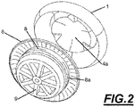
Figure 2 shows an exploded bottom view of the cap for glass bottles. -
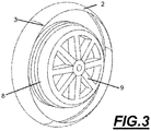
Figure 3 shows a view of the cap for glass bottles from the lower part thereof. -
Figure 4 shows a second view of the cap for glass bottles from the lower part thereof. -
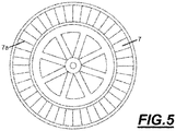
Figure 5 shows a plan view of the lower part of the cap. - The attached drawings show a preferred embodiment of the invention. More specifically, the cap for glass bottles comprises a body (1) with skirting (2) with at least three cuts (3) made from the outside of the skirting (2) to the inside of the body (1) in which a core (4) is provided and to which pressure is applied for opening the cap herein described.
- At least three reinforcements (5) in the form of ribs are reinforcing the core, the function of which is to provide greater robustness to the assembly and prevent excessive deformation of the body (1) since said reinforcements (5) do not deform during opening.
- A first concave region (4a) that coincides with a second concave region (6a) arranged in the opposite position and which is an integral part of a second body (6) integrally attached to the first body (1), is provided on the inside of the body (1) and coinciding with the position of the core (4).
- Both concave regions (4a, 6a) opposite one another create a chamber or space that allows the tilting of the cap during the deformation thereof when opening it, in addition to providing certain safety to the cap itself since the pressure to be applied on the core (4) of the first body (1) while opening is homogenized, regardless of the internal pressure withstood by the cap.
- The second body (6) comprises a flange (7) around the periphery configured, on the one hand, for fitting onto the outer surface of the rim of the bottle, and on the other, onto the skirting (2) of the body (1), creating the mentioned second concave region (6a) in the central part therein.
- In turn, the entire periphery of said flange (7) incorporates a plurality of cuts (7a) which prevent resistance when opening, and accordingly make opening easier.
- The second body (6) also comprises in the lower part thereof a threaded area (8) in turn defining a plurality of crests (8a) improving grip on the neck of the bottle and providing the sealing required for properly preserving the liquid contained in the bottle and its properties.
- Finally, contiguous to said threaded area (8) there is provided a plurality of spokes (9) in the form of reinforcement which help to improve the results with respect to internal pressure.
- In a practical embodiment, the body (1) and the second body (6) are made forming a single body.
- In a particular embodiment, the body (1) will have a series of grooves along the skirting (2) thereof making it easier to seal it during the industrial bottling process.
Claims (3)
- A cap for glass bottles, comprising a first body (1) and a second body (6) integrally attached to the first body (1), wherein:a) the first body (1) comprises:a. a skirting (2) with at least three cuts (3) made from the outside of the skirting (2) to the inside of the body (1); characterised in that the first body further comprises:b. a core (4) with at least three reinforcement ribs (5) arranged to not deform during opening;c. a first externally concave region or area (4a) provided inside the first body (1) and coincident with the position of the core (4);b) the cap being further characterised in that the second body (6) comprises:wherein the first concave region or area (4a) that coincides with the second concave region or area (6a) are opposite one another, such that they define a chamber or space there between configured for the tilting of the edge of the cap during the deformation thereof in the process of opening it.a. a flange (7) incorporating a plurality of cuts (7a) around the periphery configured for:i. fitting onto the outer surface of a rim of the glass bottle;ii. fitting onto the skirting (2) of the body (1) creating a second externally
concave region (6a) in the central part therein;b. a threaded region (8) in the lower part of the second body (6) in turn comprising:i. a plurality of crests (8a) improving grip on a neck of the glass bottle and providing the sealing required for properly preserving a liquid contained in the bottle; andc. a plurality of reinforcement spokes (9) contiguous to the threaded region (8); - The cap according to claim 1, wherein the body (1) has a plurality of grooves along its skirting (2).
- The cap according to any of the preceding claims, wherein the body (1) and the second body (6) are integrated into a single body.
Applications Claiming Priority (2)
| Application Number | Priority Date | Filing Date | Title |
|---|---|---|---|
| ES201430560A ES2551288B1 (en) | 2014-04-15 | 2014-04-15 | GLASS BOTTLE PLUG |
| PCT/ES2015/070186 WO2015158942A1 (en) | 2014-04-15 | 2015-03-17 | Cap for glass bottles |
Publications (3)
| Publication Number | Publication Date |
|---|---|
| EP3133026A4 EP3133026A4 (en) | 2017-02-22 |
| EP3133026A1 EP3133026A1 (en) | 2017-02-22 |
| EP3133026B1 true EP3133026B1 (en) | 2018-02-14 |
Family
ID=54323523
Family Applications (1)
| Application Number | Title | Priority Date | Filing Date |
|---|---|---|---|
| EP15779822.4A Not-in-force EP3133026B1 (en) | 2014-04-15 | 2015-03-17 | Cap for glass bottles |
Country Status (7)
| Country | Link |
|---|---|
| US (1) | US20170036826A1 (en) |
| EP (1) | EP3133026B1 (en) |
| CN (1) | CN106458377A (en) |
| BR (1) | BR112016024031A2 (en) |
| ES (2) | ES2551288B1 (en) |
| MX (1) | MX2016013480A (en) |
| WO (1) | WO2015158942A1 (en) |
Families Citing this family (1)
| Publication number | Priority date | Publication date | Assignee | Title |
|---|---|---|---|---|
| KR102074893B1 (en) * | 2019-01-15 | 2020-02-07 | 주식회사 에스지엠 | Container cover |
Family Cites Families (12)
| Publication number | Priority date | Publication date | Assignee | Title |
|---|---|---|---|---|
| US3109549A (en) * | 1960-06-15 | 1963-11-05 | Century Brewery Corp | Flanged plastic cork |
| US3208617A (en) * | 1964-10-12 | 1965-09-28 | Robert R Baron | Container closure means |
| US3217916A (en) * | 1964-10-28 | 1965-11-16 | Nat Can Corp | Manually removable crown cap |
| US3675805A (en) * | 1970-01-21 | 1972-07-11 | Victor Shane | Snap open bottle cap |
| US3774794A (en) * | 1971-07-12 | 1973-11-27 | C Bateman | Locking safety screw closure |
| US3764033A (en) * | 1971-11-26 | 1973-10-09 | B Smith | Safety bottle cap |
| DE2813940A1 (en) * | 1977-04-23 | 1978-10-26 | Zensho Honma | BOTTLE CAP |
| US5582309A (en) * | 1991-03-18 | 1996-12-10 | Ribi Invest Aps | Manually removable crown cap |
| FR2696996B1 (en) * | 1992-10-19 | 1995-01-06 | Capsules Metalliques Ste Lorra | Temporary corking device for bottle. |
| US8534476B2 (en) * | 2009-12-11 | 2013-09-17 | Rexam Healthcare Packaging Inc. | Child-resistant closure shell, closure, and package |
| CN102267591A (en) * | 2010-06-03 | 2011-12-07 | 刘益民 | Double-layer crown bottle cap with screwed outer layer |
| EP2599729A1 (en) * | 2010-07-27 | 2013-06-05 | Clipps Aluminium Systems S.L. | Lid for glass bottles |
-
2014
- 2014-04-15 ES ES201430560A patent/ES2551288B1/en not_active Expired - Fee Related
-
2015
- 2015-03-17 WO PCT/ES2015/070186 patent/WO2015158942A1/en active Application Filing
- 2015-03-17 CN CN201580020139.5A patent/CN106458377A/en active Pending
- 2015-03-17 EP EP15779822.4A patent/EP3133026B1/en not_active Not-in-force
- 2015-03-17 MX MX2016013480A patent/MX2016013480A/en unknown
- 2015-03-17 BR BR112016024031A patent/BR112016024031A2/en not_active IP Right Cessation
- 2015-03-17 ES ES15779822.4T patent/ES2672721T3/en active Active
- 2015-03-17 US US15/304,474 patent/US20170036826A1/en not_active Abandoned
Non-Patent Citations (1)
| Title |
|---|
| None * |
Also Published As
| Publication number | Publication date |
|---|---|
| CN106458377A (en) | 2017-02-22 |
| WO2015158942A1 (en) | 2015-10-22 |
| ES2672721T3 (en) | 2018-06-15 |
| EP3133026A4 (en) | 2017-02-22 |
| MX2016013480A (en) | 2017-03-06 |
| US20170036826A1 (en) | 2017-02-09 |
| ES2551288B1 (en) | 2016-09-08 |
| ES2551288A1 (en) | 2015-11-17 |
| BR112016024031A2 (en) | 2017-08-15 |
| EP3133026A1 (en) | 2017-02-22 |
Similar Documents
| Publication | Publication Date | Title |
|---|---|---|
| US4564116A (en) | Closure cap for beverage containers | |
| AU2016248892B2 (en) | Re-closable container | |
| RU2493076C2 (en) | Set of container and lid | |
| CA1060815A (en) | Push-in easy-opening closures | |
| RU2263059C2 (en) | Bottle closure with one-way valve | |
| AU2017304110B2 (en) | Closure with tamper-evident band | |
| MX2015004085A (en) | Container, closure, and package. | |
| EP1379441B2 (en) | A closure | |
| US8931243B2 (en) | Hot-fill method | |
| EP2084077B1 (en) | Can closure arrangement | |
| EP3133026B1 (en) | Cap for glass bottles | |
| US20090250465A1 (en) | Closure With Flexible Diaphragm | |
| US7784251B2 (en) | Crown-like twist-off closure | |
| MXPA02004575A (en) | Closure cap. | |
| US20210070509A1 (en) | Closure | |
| EP2256053B1 (en) | A spout for a metallic container with a cap and an anti-pry ring | |
| US20050230342A1 (en) | Tamperproof closing element for beverage containers | |
| WO2001010731A1 (en) | A closure arrangement for cans | |
| CA2572809A1 (en) | Closure for a container, especially a bottle | |
| WO1999026855A1 (en) | Closures for pressurised products | |
| WO2006120539A2 (en) | Plastic closure element for containers for liquids | |
| KR20040038799A (en) | A closure with tamper-evident seal for containers of liquid particuarly bottles | |
| EP3608244B1 (en) | Metal container with closure | |
| US20230339659A1 (en) | Child-resistant can top | |
| RU208193U1 (en) | SEALING CAP |
Legal Events
| Date | Code | Title | Description |
|---|---|---|---|
| PUAI | Public reference made under article 153(3) epc to a published international application that has entered the european phase |
Free format text: ORIGINAL CODE: 0009012 |
|
| 17P | Request for examination filed |
Effective date: 20161104 |
|
| A4 | Supplementary search report drawn up and despatched |
Effective date: 20161206 |
|
| AK | Designated contracting states |
Kind code of ref document: A1 Designated state(s): AL AT BE BG CH CY CZ DE DK EE ES FI FR GB GR HR HU IE IS IT LI LT LU LV MC MK MT NL NO PL PT RO RS SE SI SK SM TR |
|
| AX | Request for extension of the european patent |
Extension state: BA ME |
|
| 17Q | First examination report despatched |
Effective date: 20170307 |
|
| DAV | Request for validation of the european patent (deleted) | ||
| DAX | Request for extension of the european patent (deleted) | ||
| GRAP | Despatch of communication of intention to grant a patent |
Free format text: ORIGINAL CODE: EPIDOSNIGR1 |
|
| INTG | Intention to grant announced |
Effective date: 20170828 |
|
| GRAS | Grant fee paid |
Free format text: ORIGINAL CODE: EPIDOSNIGR3 |
|
| GRAA | (expected) grant |
Free format text: ORIGINAL CODE: 0009210 |
|
| AK | Designated contracting states |
Kind code of ref document: B1 Designated state(s): AL AT BE BG CH CY CZ DE DK EE ES FI FR GB GR HR HU IE IS IT LI LT LU LV MC MK MT NL NO PL PT RO RS SE SI SK SM TR |
|
| REG | Reference to a national code |
Ref country code: GB Ref legal event code: FG4D |
|
| REG | Reference to a national code |
Ref country code: CH Ref legal event code: EP |
|
| REG | Reference to a national code |
Ref country code: IE Ref legal event code: FG4D |
|
| REG | Reference to a national code |
Ref country code: DE Ref legal event code: R096 Ref document number: 602015008059 Country of ref document: DE Ref country code: AT Ref legal event code: REF Ref document number: 969696 Country of ref document: AT Kind code of ref document: T Effective date: 20180315 |
|
| REG | Reference to a national code |
Ref country code: FR Ref legal event code: PLFP Year of fee payment: 4 |
|
| REG | Reference to a national code |
Ref country code: ES Ref legal event code: FG2A Ref document number: 2672721 Country of ref document: ES Kind code of ref document: T3 Effective date: 20180615 |
|
| REG | Reference to a national code |
Ref country code: NL Ref legal event code: MP Effective date: 20180214 |
|
| REG | Reference to a national code |
Ref country code: AT Ref legal event code: MK05 Ref document number: 969696 Country of ref document: AT Kind code of ref document: T Effective date: 20180214 |
|
| PG25 | Lapsed in a contracting state [announced via postgrant information from national office to epo] |
Ref country code: NO Free format text: LAPSE BECAUSE OF FAILURE TO SUBMIT A TRANSLATION OF THE DESCRIPTION OR TO PAY THE FEE WITHIN THE PRESCRIBED TIME-LIMIT Effective date: 20180514 Ref country code: FI Free format text: LAPSE BECAUSE OF FAILURE TO SUBMIT A TRANSLATION OF THE DESCRIPTION OR TO PAY THE FEE WITHIN THE PRESCRIBED TIME-LIMIT Effective date: 20180214 Ref country code: CY Free format text: LAPSE BECAUSE OF FAILURE TO SUBMIT A TRANSLATION OF THE DESCRIPTION OR TO PAY THE FEE WITHIN THE PRESCRIBED TIME-LIMIT Effective date: 20180214 Ref country code: HR Free format text: LAPSE BECAUSE OF FAILURE TO SUBMIT A TRANSLATION OF THE DESCRIPTION OR TO PAY THE FEE WITHIN THE PRESCRIBED TIME-LIMIT Effective date: 20180214 Ref country code: NL Free format text: LAPSE BECAUSE OF FAILURE TO SUBMIT A TRANSLATION OF THE DESCRIPTION OR TO PAY THE FEE WITHIN THE PRESCRIBED TIME-LIMIT Effective date: 20180214 Ref country code: LT Free format text: LAPSE BECAUSE OF FAILURE TO SUBMIT A TRANSLATION OF THE DESCRIPTION OR TO PAY THE FEE WITHIN THE PRESCRIBED TIME-LIMIT Effective date: 20180214 |
|
| PGFP | Annual fee paid to national office [announced via postgrant information from national office to epo] |
Ref country code: DE Payment date: 20180515 Year of fee payment: 4 |
|
| PG25 | Lapsed in a contracting state [announced via postgrant information from national office to epo] |
Ref country code: GR Free format text: LAPSE BECAUSE OF FAILURE TO SUBMIT A TRANSLATION OF THE DESCRIPTION OR TO PAY THE FEE WITHIN THE PRESCRIBED TIME-LIMIT Effective date: 20180515 Ref country code: LV Free format text: LAPSE BECAUSE OF FAILURE TO SUBMIT A TRANSLATION OF THE DESCRIPTION OR TO PAY THE FEE WITHIN THE PRESCRIBED TIME-LIMIT Effective date: 20180214 Ref country code: AT Free format text: LAPSE BECAUSE OF FAILURE TO SUBMIT A TRANSLATION OF THE DESCRIPTION OR TO PAY THE FEE WITHIN THE PRESCRIBED TIME-LIMIT Effective date: 20180214 Ref country code: SE Free format text: LAPSE BECAUSE OF FAILURE TO SUBMIT A TRANSLATION OF THE DESCRIPTION OR TO PAY THE FEE WITHIN THE PRESCRIBED TIME-LIMIT Effective date: 20180214 Ref country code: BG Free format text: LAPSE BECAUSE OF FAILURE TO SUBMIT A TRANSLATION OF THE DESCRIPTION OR TO PAY THE FEE WITHIN THE PRESCRIBED TIME-LIMIT Effective date: 20180514 Ref country code: RS Free format text: LAPSE BECAUSE OF FAILURE TO SUBMIT A TRANSLATION OF THE DESCRIPTION OR TO PAY THE FEE WITHIN THE PRESCRIBED TIME-LIMIT Effective date: 20180214 |
|
| PGFP | Annual fee paid to national office [announced via postgrant information from national office to epo] |
Ref country code: FR Payment date: 20180514 Year of fee payment: 4 |
|
| PG25 | Lapsed in a contracting state [announced via postgrant information from national office to epo] |
Ref country code: PL Free format text: LAPSE BECAUSE OF FAILURE TO SUBMIT A TRANSLATION OF THE DESCRIPTION OR TO PAY THE FEE WITHIN THE PRESCRIBED TIME-LIMIT Effective date: 20180214 Ref country code: AL Free format text: LAPSE BECAUSE OF FAILURE TO SUBMIT A TRANSLATION OF THE DESCRIPTION OR TO PAY THE FEE WITHIN THE PRESCRIBED TIME-LIMIT Effective date: 20180214 Ref country code: RO Free format text: LAPSE BECAUSE OF FAILURE TO SUBMIT A TRANSLATION OF THE DESCRIPTION OR TO PAY THE FEE WITHIN THE PRESCRIBED TIME-LIMIT Effective date: 20180214 Ref country code: IT Free format text: LAPSE BECAUSE OF FAILURE TO SUBMIT A TRANSLATION OF THE DESCRIPTION OR TO PAY THE FEE WITHIN THE PRESCRIBED TIME-LIMIT Effective date: 20180214 Ref country code: EE Free format text: LAPSE BECAUSE OF FAILURE TO SUBMIT A TRANSLATION OF THE DESCRIPTION OR TO PAY THE FEE WITHIN THE PRESCRIBED TIME-LIMIT Effective date: 20180214 |
|
| REG | Reference to a national code |
Ref country code: CH Ref legal event code: PL |
|
| REG | Reference to a national code |
Ref country code: DE Ref legal event code: R097 Ref document number: 602015008059 Country of ref document: DE |
|
| PG25 | Lapsed in a contracting state [announced via postgrant information from national office to epo] |
Ref country code: CZ Free format text: LAPSE BECAUSE OF FAILURE TO SUBMIT A TRANSLATION OF THE DESCRIPTION OR TO PAY THE FEE WITHIN THE PRESCRIBED TIME-LIMIT Effective date: 20180214 Ref country code: SM Free format text: LAPSE BECAUSE OF FAILURE TO SUBMIT A TRANSLATION OF THE DESCRIPTION OR TO PAY THE FEE WITHIN THE PRESCRIBED TIME-LIMIT Effective date: 20180214 Ref country code: DK Free format text: LAPSE BECAUSE OF FAILURE TO SUBMIT A TRANSLATION OF THE DESCRIPTION OR TO PAY THE FEE WITHIN THE PRESCRIBED TIME-LIMIT Effective date: 20180214 Ref country code: MC Free format text: LAPSE BECAUSE OF FAILURE TO SUBMIT A TRANSLATION OF THE DESCRIPTION OR TO PAY THE FEE WITHIN THE PRESCRIBED TIME-LIMIT Effective date: 20180214 Ref country code: SK Free format text: LAPSE BECAUSE OF FAILURE TO SUBMIT A TRANSLATION OF THE DESCRIPTION OR TO PAY THE FEE WITHIN THE PRESCRIBED TIME-LIMIT Effective date: 20180214 |
|
| REG | Reference to a national code |
Ref country code: BE Ref legal event code: MM Effective date: 20180331 |
|
| PLBE | No opposition filed within time limit |
Free format text: ORIGINAL CODE: 0009261 |
|
| STAA | Information on the status of an ep patent application or granted ep patent |
Free format text: STATUS: NO OPPOSITION FILED WITHIN TIME LIMIT |
|
| REG | Reference to a national code |
Ref country code: IE Ref legal event code: MM4A |
|
| PG25 | Lapsed in a contracting state [announced via postgrant information from national office to epo] |
Ref country code: LU Free format text: LAPSE BECAUSE OF NON-PAYMENT OF DUE FEES Effective date: 20180317 |
|
| 26N | No opposition filed |
Effective date: 20181115 |
|
| PG25 | Lapsed in a contracting state [announced via postgrant information from national office to epo] |
Ref country code: IE Free format text: LAPSE BECAUSE OF NON-PAYMENT OF DUE FEES Effective date: 20180317 |
|
| PG25 | Lapsed in a contracting state [announced via postgrant information from national office to epo] |
Ref country code: BE Free format text: LAPSE BECAUSE OF NON-PAYMENT OF DUE FEES Effective date: 20180331 Ref country code: CH Free format text: LAPSE BECAUSE OF NON-PAYMENT OF DUE FEES Effective date: 20180331 Ref country code: LI Free format text: LAPSE BECAUSE OF NON-PAYMENT OF DUE FEES Effective date: 20180331 Ref country code: SI Free format text: LAPSE BECAUSE OF FAILURE TO SUBMIT A TRANSLATION OF THE DESCRIPTION OR TO PAY THE FEE WITHIN THE PRESCRIBED TIME-LIMIT Effective date: 20180214 |
|
| REG | Reference to a national code |
Ref country code: DE Ref legal event code: R119 Ref document number: 602015008059 Country of ref document: DE |
|
| GBPC | Gb: european patent ceased through non-payment of renewal fee |
Effective date: 20190317 |
|
| PG25 | Lapsed in a contracting state [announced via postgrant information from national office to epo] |
Ref country code: DE Free format text: LAPSE BECAUSE OF NON-PAYMENT OF DUE FEES Effective date: 20191001 Ref country code: MT Free format text: LAPSE BECAUSE OF NON-PAYMENT OF DUE FEES Effective date: 20180317 Ref country code: GB Free format text: LAPSE BECAUSE OF NON-PAYMENT OF DUE FEES Effective date: 20190317 |
|
| PG25 | Lapsed in a contracting state [announced via postgrant information from national office to epo] |
Ref country code: FR Free format text: LAPSE BECAUSE OF NON-PAYMENT OF DUE FEES Effective date: 20190331 |
|
| PG25 | Lapsed in a contracting state [announced via postgrant information from national office to epo] |
Ref country code: TR Free format text: LAPSE BECAUSE OF FAILURE TO SUBMIT A TRANSLATION OF THE DESCRIPTION OR TO PAY THE FEE WITHIN THE PRESCRIBED TIME-LIMIT Effective date: 20180214 |
|
| PG25 | Lapsed in a contracting state [announced via postgrant information from national office to epo] |
Ref country code: PT Free format text: LAPSE BECAUSE OF FAILURE TO SUBMIT A TRANSLATION OF THE DESCRIPTION OR TO PAY THE FEE WITHIN THE PRESCRIBED TIME-LIMIT Effective date: 20180214 |
|
| PG25 | Lapsed in a contracting state [announced via postgrant information from national office to epo] |
Ref country code: MK Free format text: LAPSE BECAUSE OF NON-PAYMENT OF DUE FEES Effective date: 20180214 Ref country code: HU Free format text: LAPSE BECAUSE OF FAILURE TO SUBMIT A TRANSLATION OF THE DESCRIPTION OR TO PAY THE FEE WITHIN THE PRESCRIBED TIME-LIMIT; INVALID AB INITIO Effective date: 20150317 |
|
| PG25 | Lapsed in a contracting state [announced via postgrant information from national office to epo] |
Ref country code: IS Free format text: LAPSE BECAUSE OF FAILURE TO SUBMIT A TRANSLATION OF THE DESCRIPTION OR TO PAY THE FEE WITHIN THE PRESCRIBED TIME-LIMIT Effective date: 20180614 |
|
| PGFP | Annual fee paid to national office [announced via postgrant information from national office to epo] |
Ref country code: ES Payment date: 20200403 Year of fee payment: 6 |
|
| REG | Reference to a national code |
Ref country code: ES Ref legal event code: FD2A Effective date: 20220523 |
|
| PG25 | Lapsed in a contracting state [announced via postgrant information from national office to epo] |
Ref country code: ES Free format text: LAPSE BECAUSE OF NON-PAYMENT OF DUE FEES Effective date: 20210318 |