EP3132998A1 - Wheel and moving device - Google Patents
Wheel and moving device Download PDFInfo
- Publication number
- EP3132998A1 EP3132998A1 EP14881860.2A EP14881860A EP3132998A1 EP 3132998 A1 EP3132998 A1 EP 3132998A1 EP 14881860 A EP14881860 A EP 14881860A EP 3132998 A1 EP3132998 A1 EP 3132998A1
- Authority
- EP
- European Patent Office
- Prior art keywords
- wheel
- outer wheel
- movement path
- moving device
- exemplary embodiment
- Prior art date
- Legal status (The legal status is an assumption and is not a legal conclusion. Google has not performed a legal analysis and makes no representation as to the accuracy of the status listed.)
- Granted
Links
Images



Classifications
-
- B—PERFORMING OPERATIONS; TRANSPORTING
- B60—VEHICLES IN GENERAL
- B60B—VEHICLE WHEELS; CASTORS; AXLES FOR WHEELS OR CASTORS; INCREASING WHEEL ADHESION
- B60B9/00—Wheels of high resiliency, e.g. with conical interacting pressure-surfaces
-
- B—PERFORMING OPERATIONS; TRANSPORTING
- B60—VEHICLES IN GENERAL
- B60B—VEHICLE WHEELS; CASTORS; AXLES FOR WHEELS OR CASTORS; INCREASING WHEEL ADHESION
- B60B9/00—Wheels of high resiliency, e.g. with conical interacting pressure-surfaces
- B60B9/02—Wheels of high resiliency, e.g. with conical interacting pressure-surfaces using springs resiliently mounted bicycle rims
- B60B9/10—Wheels of high resiliency, e.g. with conical interacting pressure-surfaces using springs resiliently mounted bicycle rims of rubber or the like
- B60B9/12—Wheels of high resiliency, e.g. with conical interacting pressure-surfaces using springs resiliently mounted bicycle rims of rubber or the like in the form of sleeves or rings concentric with the wheel axis
-
- B—PERFORMING OPERATIONS; TRANSPORTING
- B60—VEHICLES IN GENERAL
- B60B—VEHICLE WHEELS; CASTORS; AXLES FOR WHEELS OR CASTORS; INCREASING WHEEL ADHESION
- B60B9/00—Wheels of high resiliency, e.g. with conical interacting pressure-surfaces
- B60B9/02—Wheels of high resiliency, e.g. with conical interacting pressure-surfaces using springs resiliently mounted bicycle rims
- B60B9/10—Wheels of high resiliency, e.g. with conical interacting pressure-surfaces using springs resiliently mounted bicycle rims of rubber or the like
- B60B9/14—Wheels of high resiliency, e.g. with conical interacting pressure-surfaces using springs resiliently mounted bicycle rims of rubber or the like with means limiting relative lateral movements between hub and remainder of wheel
Definitions
- the present invention relates to a wheel in which an outer wheel is rotated, and to a moving device in which a moving body is moved by an outer wheel rotating.
- JP-A Japanese Patent Application Laid-Open ( JP-A) No. 2013-71659 describes a tire wheel assembly in which a tire is assembled to an outer periphery of a wheel, and the inside of the tire is filled with air.
- an object of the present invention is to obtain a wheel and moving device capable of raising cushioning performance.
- a wheel of a first aspect of the present invention includes: an outer wheel that is configured in an annular shape, that has elastic properties, and that, when placed on a movement path, includes a contact portion contacting the movement path and undergoing elastic deformation wholly in a radial direction toward the opposite side to the movement path; and a support body that rotatably supports the outer wheel.
- a wheel of a second aspect of the present invention includes: an outer wheel that is configured in an annular shape and that has elastic properties; and a support body that rotatably supports the outer wheel, and that is disposed at a separation from a peripheral direction portion of the outer wheel, the peripheral portion contacting a movement path of the outer wheel when the outer wheel has been placed on the movement path and undergoing elastic deformation toward the opposite side to the movement path.
- a wheel of a third aspect of the present invention includes an outer wheel that is configured by a circular ring shaped crawler track, and that has elastic properties.
- a wheel of a fourth aspect of the present invention is the wheel of either the first aspect or the second aspect, further including an inner wheel that is provided to the support body, that is capable of rotating, and that rotatably supports the outer wheel.
- a wheel of a fifth aspect of the present invention is the wheel of any one of the first aspect to the fourth aspect, further including a suppression portion that is provided to an outer periphery of the outer wheel, and that suppresses slippage with respect to a movement path.
- a moving device of a sixth aspect of the present invention includes the wheel of any one of the first aspect to the fifth aspect; and a moving body that supports the outer wheel, and that is moved by the outer wheel being rotated in a state placed on a movement path.
- a moving device of a seventh aspect of the present invention is the moving device of the sixth aspect, further including drive means that drives and rotates the outer wheel.
- the outer wheel is configured in an annular shape, and has elastic properties.
- the support body rotatably supports the outer wheel. Accordingly, the wheel is moved by the outer wheel being rotated in a state in which the outer wheel has been placed on the movement path.
- the contact portion of the outer wheel that contacts the movement path is elastically deformed wholly in the radial direction toward the opposite side to the movement path. This thereby enables the elastic force of the outer wheel to be suppressed from being dispersed in an axial direction of the outer wheel, and enables cushioning performance to be raised.
- the outer wheel is configured in an annular shape, and has elastic properties.
- the support body rotatably supports the outer wheel. This thereby enables the wheel to be moved by being rotated in a state in which the outer wheel has been placed on the movement path.
- the support body When the outer wheel has been placed on the movement path and has undergone elastic deformation toward the opposite side to the movement path, the support body is disposed at a separation from the peripheral direction portion of the outer wheel that contacts the movement path. This thereby enables the elastic force of the outer wheel to be suppressed from being dispersed in the axial direction, and enables cushioning performance to be raised.
- the outer wheel is configured by the crawler track, and has elastic properties.
- the wheel is accordingly moved by being rotated in a state in which the outer wheel has been placed on the movement path.
- the outer wheel is configured in a circular ring shape. Accordingly, when the outer wheel is placed on the movement path and has undergone elastic deformation toward the opposite side to the movement path, the outer wheel is elastically deformed at the contact portion that contacts the movement path and in the vicinity of the contact portion in the peripheral direction. This thereby enables the elastic force of the outer wheel to be suppressed from being dispersed in the axial direction, and enables cushioning performance to be raised.
- the inner wheel is provided to the support body, and the inner wheel rotatably supports the outer wheel.
- the inner wheel is capable of rotating. This thereby enables rotational performance of the outer wheel to be raised.
- the suppression portion is provided to the outer periphery of the outer wheel, and the suppression portion suppresses slippage with respect to the movement path. This thereby enables slippage of the outer wheel with respect to the movement path to be suppressed.
- the moving device of the sixth aspect of the present invention includes the wheel of any one of the first aspect to the fifth aspect of the present invention.
- the moving body supports the outer wheel, and is moved by the outer wheel being rotated in a state placed on the movement path.
- the wheel of any one of the first aspect to the fifth aspect of the present invention is provided therein. This thereby enables similar advantageous effects to be obtained to those of any one out of the first aspect to the fifth aspect of the present invention.
- the drive means drives and rotates the outer wheel. This thereby enables the moving body to be moved by the drive force of the drive means.
- Fig. 1 is a perspective view illustrating a moving device 10 according to a first exemplary embodiment of the present invention.
- Fig. 2 is a side view illustrating relevant portions of the moving device 10. Note that in the drawings, the arrow FR indicates the front of the moving device 10, the arrow RH indicates the right of the moving device 10, and the arrow UP indicates upward.
- the moving device 10 includes a moving body 12.
- a lower face of the moving body 12 is provided with a pair of forks 14 serving as coupling members, each having a cross-section resembling an inverted U-shape.
- the forks 14 are disposed on a right side and a left side of the moving body 12.
- An upper wall of each fork 14 is fixed to the lower face of the moving body 12.
- Each fork 14 includes a pair of side walls facing each other along a left-right direction.
- a circular column shaped axle 16 is rotatably supported between the pair of side walls of each fork 14. The axial direction of the axle 16 is disposed parallel to the left-right direction.
- a wheel 18 is provided between the pair of side walls of each fork 14.
- a support body 20 is provided at an inner portion of each wheel 18.
- Each support body 20 is provided with a pair of elongated, flat plate shaped frames 22, serving as support members.
- the frames 22 are swingably supported on the axle 16 at their length direction centers, and are disposed parallel to a front-rear direction.
- Circular column shaped support shafts 24 are rotatably supported between front end portions and between rear end portions of each pair of frames 22. The axial direction of the support shafts 24 is disposed parallel to the left-right direction.
- Each support body 20 is provided with a pair of substantially circular column shaped inner wheels 26.
- the inner wheels 26 are coaxially supported on the respective support shafts 24, and are capable of rotating about the support shafts 24.
- Each inner wheel 26 is disposed between the pair of frames 22, thereby restricting movement of the inner wheel 26 in the left-right direction.
- Each of the inner wheels 26 is provided with a coaxial circular column shaped inner wheel body 26A, and coaxial, annular flat disk shaped flanges 26B are integrally provided at both axial direction ends of the inner wheel body 26A.
- each flange 26B is larger than a diameter dimension of the inner wheel bodies 26A, such that the flanges 26B project out toward a radial direction outside of the inner wheel body 26A around the entire periphery of the inner wheel body 26A.
- a circular cylinder shaped (ring shaped) outer wheel 28 (continuous track, crawler track) is provided at an outer peripheral portion of the wheel 18.
- the outer wheel 28 is disposed at the peripheral outside of the pair of inner wheels 26.
- a front end portion and a rear end portion of the outer wheel 28 are disposed in a state in which movement in the left-right direction is restricted to between the respective flanges 26B of the front side and rear side inner wheels 26.
- a front end portion of an inner peripheral face of the outer wheel 28 is contacted by the front end of an outer peripheral face of the inner wheel body 26A of the front side inner wheel 26, and a rear end portion of the inner peripheral face of the outer wheel 28 is contacted by the rear end of an outer peripheral face of the inner wheel body 26A of the rear side inner wheel 26.
- the outer wheel 28 is supported so as to be capable of rotating around the pair of inner wheels 26, so as to enable the pair of inner wheels 26 and the outer wheel 28 to be rotated at the same time as each other by at least one out of the pair of inner wheels 26 or the outer wheel 28 being rotated.
- a circular cylinder shaped rim 28A serving as an outer wheel body, is provided at an inner portion of the outer wheel 28.
- the rim 28A is, for example, made from carbon fiber or from a synthetic resin, so as to configure a robust flat spring with a circular ring shape.
- the rim 28A is elastic and flexible, and has high rebound properties (shape recovery properties).
- a circular cylinder shaped suppression portion 28B is fixed to an outer peripheral face of the rim 28A.
- the suppression portion 28B is made from rubber, for example, and is elastic and flexible.
- the front end portion and the rear end portion of the outer wheel 28 were to be entrained around the outer periphery of the front side half of the front side inner wheel 26 and the rear side half of the rear side inner wheel 26 respectively, and, except for at the front end portion and the rear end portion, the outer wheel 28 were to extend in a straight line between the front side inner wheel 26 and the rear side inner wheel 26.
- the outer wheel 28 would not exhibit cushioning properties.
- the outer wheel 28 is configured in a circular ring shape. Accordingly, as illustrated in Fig.
- each outer wheel 28 is elastically deformed toward the opposite side to the movement path 30, and assumes a shape conforming to the surface (upper face) of the movement path 30.
- the outer wheel 28 is elastically deformed around the inner wheels 26, enlarging the outer wheel 28 along the front-rear direction in a state in which the curvature of the outer wheel 28 is increased in the vicinity of the lower side of the inner wheels 26.
- the outer wheel 28 is rotated, rotating the inner wheels 26.
- the frames 22 swing with respect to the forks 14 as necessary, the wheel 18 is moved in the front-rear direction, and the moving body 12 is moved in the front-rear direction.
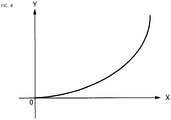
- this enables the ratio of increase in a shape recovery force of the lower end portion of the outer wheel 28 toward the lower side (see the Y-axis) with respect to an increase in a movement amount of a lower end portion of the outer wheel 28 toward the upper side (see the X-axis) to be made larger.
- This thereby enables cushioning properties of the moving device 10 (wheel 18) to be raised when the moving device 10 moves in the front-rear direction, and enables smooth movement of the moving device 10 at high speed even when the movement path 30 runs over rough ground (for example a gravel path).
- Each of the wheels 18 is also configured such that the outer wheel 28 is rotatably supported by the pair of rotatable inner wheels 26. This thereby enables efficient (smooth) rotation of the outer wheel 28, enabling rotation performance of the outer wheel 28 to be raised, and enables efficient movement of the moving device 10 (wheel 18) in the front-rear direction even when the movement path 30 runs over rough ground. Moreover, unlike a tire wheel assembly, the wheel 18 can be made smaller and made lighter, enabling a reduction in the cost of the wheel 18, and enabling the wheel 18 to be easily applied to a small moving device 10.
- the suppression portion 28B is fixed to the outer peripheral portion of the outer wheel 28, and the suppression portion 28B suppresses slippage with respect to the movement path 30. This thereby enables slippage of the outer wheel 28 with respect to the movement path 30 to be suppressed. Moreover, unlike in a tire wheel assembly, the possibility of the outer wheel 28 sustaining a puncture can be eliminated.
- the rim 28A of the outer wheel 28 is configured by a robust flat spring. This thereby enables the occurrence of wobble of the moving device 10 (of the wheel 18) to be suppressed during movement of the moving device 10 in the front-rear direction.
- the load from the moving body 12 can be borne by the inner wheels 26 through the forks 14, the wheel shaft 16, the frames 22, and the support shafts 24. Accordingly, the moving device 10 can be moved by rotating the inner wheels 26, thereby enabling the moving device 10 to be moved easily.
- Fig. 5 is a side view illustrating a state in which a moving device 50 of a second exemplary embodiment of the present invention has been placed on the movement path 30.
- the moving device 50 is configured similarly to the first exemplary embodiment described above, but differs in the following points.
- the moving body 12 is provided with a motor (not illustrated in the drawings) serving as a drive means, and a first sprocket 52 that is coaxially and rotatably supported on the wheel shaft 16 of the forks 14 and configures a transmission means.
- the motor and the first sprocket 52 are coupled together by a first chain 54 configuring the transmission means.
- a second sprocket 56 configuring the transmission means is coaxially and rotatably supported on one (for example the rear side) support shaft 24 of the support body 20.
- the second sprocket 56 is coupled to the first sprocket 52 by a second chain 58 configuring the transmission means.
- the second sprocket 56 is fixed to one (for example the rear side) inner wheel 26, such that the second sprocket 56 and the one inner wheel 26 are capable of rotating together as a unit.
- Outer teeth (not illustrated in the drawings) and inner teeth (not illustrated in the drawings), for example, each configuring the transmission means, are respectively provided to the entire outer peripheral face of the inner wheel body 26A of the one inner wheel 26, and to the entire inner peripheral face of the outer wheel 28 (rim 28A).
- the outer teeth and the inner teeth mesh together with each other so as to limit relative rotation (slippage) between the inner wheels 26 and the outer wheel 28.
- the present exemplary embodiment is also capable of exhibiting similar operation and advantageous effects to those of the first exemplary embodiment described above.
- driving the motor transmits motive force (drive force) of the motor to the outer wheel 28 (inner teeth), through the first chain 54, the first sprocket 52, the second chain 58, the second sprocket 56, and the one inner wheel 26 (outer teeth).
- driving the motor transmits motive force (drive force) of the motor to the outer wheel 28 (inner teeth), through the first chain 54, the first sprocket 52, the second chain 58, the second sprocket 56, and the one inner wheel 26 (outer teeth).
- the forks 14 are fixed to the lower face of the moving body 12.
- the forks 14 may be supported so as to be rotatable about a vertical axis.
- each support body 20 is provided with a pair of the inner wheels 26 in the first exemplary embodiment and the second exemplary embodiment.
- each support body 20 may be provided with three or more inner wheels 26.
- the rim 28A of the outer wheel 28 is configured by a circular ring shaped, robust flat spring in the first exemplary embodiment and the second exemplary embodiment described above.
- the rim 28A of the outer wheel 28 may be configured by a circular ring shaped, robust coil spring or pipe member.
- the moving device 10 is provided with the pair of forks 14 (each including the wheel shaft 16) and the pair of the wheels 18 in the first exemplary embodiment and the second exemplary embodiment.
- the moving device 10 may be respectively provided with a single, or three or more, of the forks 14 (including the wheel shaft 16) and the wheels 18.
- the moving device 10 of the first exemplary embodiment and the second exemplary embodiment may be applied to handcarts (shopping carts and the like), wheelchairs, pushchairs, dollies, roller suitcases, roller skates, automobiles, motorcycles, bicycles, heavy industrial equipment, or space exploration vehicles.
Landscapes
- Engineering & Computer Science (AREA)
- Mechanical Engineering (AREA)
- Tires In General (AREA)
- Handcart (AREA)
Description
- The present invention relates to a wheel in which an outer wheel is rotated, and to a moving device in which a moving body is moved by an outer wheel rotating.
- Japanese Patent Application Laid-Open (
JP-A) No. 2013-71659 - In this tire wheel assembly, when the tire is placed on a movement path, elastic force of the tire acts toward the side of the movement path, but is also dispersed in an axial direction of the tire.
- In consideration of the above circumstances, an object of the present invention is to obtain a wheel and moving device capable of raising cushioning performance.
- A wheel of a first aspect of the present invention includes: an outer wheel that is configured in an annular shape, that has elastic properties, and that, when placed on a movement path, includes a contact portion contacting the movement path and undergoing elastic deformation wholly in a radial direction toward the opposite side to the movement path; and a support body that rotatably supports the outer wheel.
- A wheel of a second aspect of the present invention includes: an outer wheel that is configured in an annular shape and that has elastic properties; and a support body that rotatably supports the outer wheel, and that is disposed at a separation from a peripheral direction portion of the outer wheel, the peripheral portion contacting a movement path of the outer wheel when the outer wheel has been placed on the movement path and undergoing elastic deformation toward the opposite side to the movement path.
- A wheel of a third aspect of the present invention includes an outer wheel that is configured by a circular ring shaped crawler track, and that has elastic properties.
- A wheel of a fourth aspect of the present invention is the wheel of either the first aspect or the second aspect, further including an inner wheel that is provided to the support body, that is capable of rotating, and that rotatably supports the outer wheel.
- A wheel of a fifth aspect of the present invention is the wheel of any one of the first aspect to the fourth aspect, further including a suppression portion that is provided to an outer periphery of the outer wheel, and that suppresses slippage with respect to a movement path.
- A moving device of a sixth aspect of the present invention includes the wheel of any one of the first aspect to the fifth aspect; and a moving body that supports the outer wheel, and that is moved by the outer wheel being rotated in a state placed on a movement path.
- A moving device of a seventh aspect of the present invention is the moving device of the sixth aspect, further including drive means that drives and rotates the outer wheel. Advantageous Effects of Invention
- In the wheel of the first aspect of the present invention, the outer wheel is configured in an annular shape, and has elastic properties. The support body rotatably supports the outer wheel. Accordingly, the wheel is moved by the outer wheel being rotated in a state in which the outer wheel has been placed on the movement path.
- When the outer wheel has been placed on the movement path, the contact portion of the outer wheel that contacts the movement path is elastically deformed wholly in the radial direction toward the opposite side to the movement path. This thereby enables the elastic force of the outer wheel to be suppressed from being dispersed in an axial direction of the outer wheel, and enables cushioning performance to be raised.
- In the wheel of the second aspect of the present invention, the outer wheel is configured in an annular shape, and has elastic properties. The support body rotatably supports the outer wheel. This thereby enables the wheel to be moved by being rotated in a state in which the outer wheel has been placed on the movement path.
- When the outer wheel has been placed on the movement path and has undergone elastic deformation toward the opposite side to the movement path, the support body is disposed at a separation from the peripheral direction portion of the outer wheel that contacts the movement path. This thereby enables the elastic force of the outer wheel to be suppressed from being dispersed in the axial direction, and enables cushioning performance to be raised.
- In the wheel of the third aspect of the present invention, the outer wheel is configured by the crawler track, and has elastic properties. The wheel is accordingly moved by being rotated in a state in which the outer wheel has been placed on the movement path.
- The outer wheel is configured in a circular ring shape. Accordingly, when the outer wheel is placed on the movement path and has undergone elastic deformation toward the opposite side to the movement path, the outer wheel is elastically deformed at the contact portion that contacts the movement path and in the vicinity of the contact portion in the peripheral direction. This thereby enables the elastic force of the outer wheel to be suppressed from being dispersed in the axial direction, and enables cushioning performance to be raised.
- In the wheel of the fourth aspect, the inner wheel is provided to the support body, and the inner wheel rotatably supports the outer wheel.
- The inner wheel is capable of rotating. This thereby enables rotational performance of the outer wheel to be raised.
- In the wheel of the fifth aspect, the suppression portion is provided to the outer periphery of the outer wheel, and the suppression portion suppresses slippage with respect to the movement path. This thereby enables slippage of the outer wheel with respect to the movement path to be suppressed.
- The moving device of the sixth aspect of the present invention includes the wheel of any one of the first aspect to the fifth aspect of the present invention. The moving body supports the outer wheel, and is moved by the outer wheel being rotated in a state placed on the movement path.
- As described above, the wheel of any one of the first aspect to the fifth aspect of the present invention is provided therein. This thereby enables similar advantageous effects to be obtained to those of any one out of the first aspect to the fifth aspect of the present invention.
- In the moving device of the seventh aspect of the present invention, the drive means drives and rotates the outer wheel. This thereby enables the moving body to be moved by the drive force of the drive means.
-
-
Fig. 1 is a perspective view illustrating a moving device according to a first exemplary embodiment of the present invention. -
Fig. 2 is a side view illustrating relevant portions of a moving device according to the first exemplary embodiment of the present invention. -
Fig. 3 is a side view illustrating a state in which a moving device according to the first exemplary embodiment of the present invention has been placed on a movement path. -
Fig. 4 is a graph illustrating a relationship between a movement amount of a lower end portion of an outer wheel toward an upper side (X axis) and a shape recovery force of the lower end portion of the outer wheel toward the lower side (Y axis), in a moving device according to the first exemplary embodiment of the present invention. -
Fig. 5 is a side view illustrating a state in which a moving device according to a second exemplary embodiment of the present invention has been placed on a movement path. -
Fig. 1 is a perspective view illustrating a movingdevice 10 according to a first exemplary embodiment of the present invention.Fig. 2 is a side view illustrating relevant portions of the movingdevice 10. Note that in the drawings, the arrow FR indicates the front of the movingdevice 10, the arrow RH indicates the right of the movingdevice 10, and the arrow UP indicates upward. - As illustrated in
Fig. 1 andFig. 2 , the movingdevice 10 according to the present exemplary embodiment includes a movingbody 12. A lower face of the movingbody 12 is provided with a pair offorks 14 serving as coupling members, each having a cross-section resembling an inverted U-shape. Theforks 14 are disposed on a right side and a left side of the movingbody 12. An upper wall of eachfork 14 is fixed to the lower face of the movingbody 12. Eachfork 14 includes a pair of side walls facing each other along a left-right direction. A circular column shapedaxle 16 is rotatably supported between the pair of side walls of eachfork 14. The axial direction of theaxle 16 is disposed parallel to the left-right direction. - A
wheel 18 is provided between the pair of side walls of eachfork 14. Asupport body 20 is provided at an inner portion of eachwheel 18. - Each
support body 20 is provided with a pair of elongated, flat plate shapedframes 22, serving as support members. Theframes 22 are swingably supported on theaxle 16 at their length direction centers, and are disposed parallel to a front-rear direction. Circular column shapedsupport shafts 24 are rotatably supported between front end portions and between rear end portions of each pair offrames 22. The axial direction of thesupport shafts 24 is disposed parallel to the left-right direction. - Each
support body 20 is provided with a pair of substantially circular column shapedinner wheels 26. Theinner wheels 26 are coaxially supported on therespective support shafts 24, and are capable of rotating about thesupport shafts 24. Eachinner wheel 26 is disposed between the pair offrames 22, thereby restricting movement of theinner wheel 26 in the left-right direction. Each of theinner wheels 26 is provided with a coaxial circular column shapedinner wheel body 26A, and coaxial, annular flat disk shapedflanges 26B are integrally provided at both axial direction ends of theinner wheel body 26A. An external diameter dimension of eachflange 26B is larger than a diameter dimension of theinner wheel bodies 26A, such that theflanges 26B project out toward a radial direction outside of theinner wheel body 26A around the entire periphery of theinner wheel body 26A. - A circular cylinder shaped (ring shaped) outer wheel 28 (continuous track, crawler track) is provided at an outer peripheral portion of the
wheel 18. Theouter wheel 28 is disposed at the peripheral outside of the pair ofinner wheels 26. A front end portion and a rear end portion of theouter wheel 28 are disposed in a state in which movement in the left-right direction is restricted to between therespective flanges 26B of the front side and rear sideinner wheels 26. A front end portion of an inner peripheral face of theouter wheel 28 is contacted by the front end of an outer peripheral face of theinner wheel body 26A of the front sideinner wheel 26, and a rear end portion of the inner peripheral face of theouter wheel 28 is contacted by the rear end of an outer peripheral face of theinner wheel body 26A of the rear sideinner wheel 26. Accordingly, theouter wheel 28 is supported so as to be capable of rotating around the pair ofinner wheels 26, so as to enable the pair ofinner wheels 26 and theouter wheel 28 to be rotated at the same time as each other by at least one out of the pair ofinner wheels 26 or theouter wheel 28 being rotated. - A circular cylinder shaped
rim 28A, serving as an outer wheel body, is provided at an inner portion of theouter wheel 28. Therim 28A is, for example, made from carbon fiber or from a synthetic resin, so as to configure a robust flat spring with a circular ring shape. Therim 28A is elastic and flexible, and has high rebound properties (shape recovery properties). A circular cylinder shapedsuppression portion 28B is fixed to an outer peripheral face of therim 28A. Thesuppression portion 28B is made from rubber, for example, and is elastic and flexible. - Suppose that the front end portion and the rear end portion of the
outer wheel 28 were to be entrained around the outer periphery of the front side half of the front sideinner wheel 26 and the rear side half of the rear sideinner wheel 26 respectively, and, except for at the front end portion and the rear end portion, theouter wheel 28 were to extend in a straight line between the front sideinner wheel 26 and the rear sideinner wheel 26. In such a configuration, theouter wheel 28 would not exhibit cushioning properties. However, as illustrated inFig. 2 , in the present exemplary embodiment theouter wheel 28 is configured in a circular ring shape. Accordingly, as illustrated inFig. 3 , when theouter wheel 28 is placed on a movement path 30 (for example on the ground) and load acts from the pair ofinner wheels 26 toward the lower side, a portion of theouter wheel 28 further to the lower side than the pair ofinner wheels 26 is elastically deformed to a large extent, enabling cushioning properties to be exhibited. - Next, explanation follows regarding operation of the present exemplary embodiment.
- As illustrated in
Fig. 3 , when theouter wheels 28 of thewheels 18 are placed on themovement path 30, such that the movingdevice 10 is placed on themovement path 30, downward load from the movingbody 12 acts on theouter wheels 28, through theforks 14, thewheel shafts 16, theframes 22, thesupport shafts 24, and theinner wheels 26. Accordingly, a lower end portion (a portion contacting themovement path 30, a peripheral direction portion that contacts the movement path 30) of eachouter wheel 28 is elastically deformed toward the opposite side to themovement path 30, and assumes a shape conforming to the surface (upper face) of themovement path 30. Moreover, theouter wheel 28 is elastically deformed around theinner wheels 26, enlarging theouter wheel 28 along the front-rear direction in a state in which the curvature of theouter wheel 28 is increased in the vicinity of the lower side of theinner wheels 26. - When the moving
device 10 moves along the front-rear direction, theouter wheel 28 is rotated, rotating theinner wheels 26. Moreover, theframes 22 swing with respect to theforks 14 as necessary, thewheel 18 is moved in the front-rear direction, and the movingbody 12 is moved in the front-rear direction. - Note that when the moving
device 10 is placed on themovement path 30, the lower end portion of theouter wheel 28 is elastically deformed wholly in the radial direction toward the opposite side to themovement path 30, and the pair ofinner wheels 26 are moved away from the lower end portion of theouter wheel 28 toward the upper side. Accordingly, elastic force of theouter wheel 28 can be prevented from dispersing in the axial direction of theouter wheel 28, and elastic force of theouter wheel 28 can be made to act efficiently toward the side of themovement path 30. As illustrated inFig. 4 , this enables the ratio of increase in a shape recovery force of the lower end portion of theouter wheel 28 toward the lower side (see the Y-axis) with respect to an increase in a movement amount of a lower end portion of theouter wheel 28 toward the upper side (see the X-axis) to be made larger. This thereby enables cushioning properties of the moving device 10 (wheel 18) to be raised when the movingdevice 10 moves in the front-rear direction, and enables smooth movement of the movingdevice 10 at high speed even when themovement path 30 runs over rough ground (for example a gravel path). - Each of the
wheels 18 is also configured such that theouter wheel 28 is rotatably supported by the pair of rotatableinner wheels 26. This thereby enables efficient (smooth) rotation of theouter wheel 28, enabling rotation performance of theouter wheel 28 to be raised, and enables efficient movement of the moving device 10 (wheel 18) in the front-rear direction even when themovement path 30 runs over rough ground. Moreover, unlike a tire wheel assembly, thewheel 18 can be made smaller and made lighter, enabling a reduction in the cost of thewheel 18, and enabling thewheel 18 to be easily applied to a small movingdevice 10. - The
suppression portion 28B is fixed to the outer peripheral portion of theouter wheel 28, and thesuppression portion 28B suppresses slippage with respect to themovement path 30. This thereby enables slippage of theouter wheel 28 with respect to themovement path 30 to be suppressed. Moreover, unlike in a tire wheel assembly, the possibility of theouter wheel 28 sustaining a puncture can be eliminated. - Moreover, the
rim 28A of theouter wheel 28 is configured by a robust flat spring. This thereby enables the occurrence of wobble of the moving device 10 (of the wheel 18) to be suppressed during movement of the movingdevice 10 in the front-rear direction. - Supposing that the
outer wheel 28 were to break, the load from the movingbody 12 can be borne by theinner wheels 26 through theforks 14, thewheel shaft 16, theframes 22, and thesupport shafts 24. Accordingly, the movingdevice 10 can be moved by rotating theinner wheels 26, thereby enabling the movingdevice 10 to be moved easily. -
Fig. 5 is a side view illustrating a state in which a movingdevice 50 of a second exemplary embodiment of the present invention has been placed on themovement path 30. - The moving
device 50 according to the present exemplary embodiment is configured similarly to the first exemplary embodiment described above, but differs in the following points. - As illustrated in
Fig. 5 , in the movingdevice 50 according to the present exemplary embodiment, the movingbody 12 is provided with a motor (not illustrated in the drawings) serving as a drive means, and afirst sprocket 52 that is coaxially and rotatably supported on thewheel shaft 16 of theforks 14 and configures a transmission means. The motor and thefirst sprocket 52 are coupled together by afirst chain 54 configuring the transmission means. - A
second sprocket 56 configuring the transmission means is coaxially and rotatably supported on one (for example the rear side)support shaft 24 of thesupport body 20. Thesecond sprocket 56 is coupled to thefirst sprocket 52 by asecond chain 58 configuring the transmission means. Thesecond sprocket 56 is fixed to one (for example the rear side)inner wheel 26, such that thesecond sprocket 56 and the oneinner wheel 26 are capable of rotating together as a unit. - Outer teeth (not illustrated in the drawings) and inner teeth (not illustrated in the drawings), for example, each configuring the transmission means, are respectively provided to the entire outer peripheral face of the
inner wheel body 26A of the oneinner wheel 26, and to the entire inner peripheral face of the outer wheel 28 (rim 28A). The outer teeth and the inner teeth mesh together with each other so as to limit relative rotation (slippage) between theinner wheels 26 and theouter wheel 28. - The present exemplary embodiment is also capable of exhibiting similar operation and advantageous effects to those of the first exemplary embodiment described above.
- Moreover, driving the motor transmits motive force (drive force) of the motor to the outer wheel 28 (inner teeth), through the
first chain 54, thefirst sprocket 52, thesecond chain 58, thesecond sprocket 56, and the one inner wheel 26 (outer teeth). This thereby enables theouter wheel 28 to be rotated by the motive force of the motor, enabling the moving device 10 (wheels 18) to be moved in the front-rear direction. - Note that in the first exemplary embodiment and the second exemplary embodiment, the
forks 14 are fixed to the lower face of the movingbody 12. However, theforks 14 may be supported so as to be rotatable about a vertical axis. - Moreover, each
support body 20 is provided with a pair of theinner wheels 26 in the first exemplary embodiment and the second exemplary embodiment. However, eachsupport body 20 may be provided with three or moreinner wheels 26. - Moreover, the
rim 28A of theouter wheel 28 is configured by a circular ring shaped, robust flat spring in the first exemplary embodiment and the second exemplary embodiment described above. However, therim 28A of theouter wheel 28 may be configured by a circular ring shaped, robust coil spring or pipe member. - Moreover, the moving
device 10 is provided with the pair of forks 14 (each including the wheel shaft 16) and the pair of thewheels 18 in the first exemplary embodiment and the second exemplary embodiment. However, the movingdevice 10 may be respectively provided with a single, or three or more, of the forks 14 (including the wheel shaft 16) and thewheels 18. - The moving
device 10 of the first exemplary embodiment and the second exemplary embodiment may be applied to handcarts (shopping carts and the like), wheelchairs, pushchairs, dollies, roller suitcases, roller skates, automobiles, motorcycles, bicycles, heavy industrial equipment, or space exploration vehicles. - The disclosure of Japanese Patent Application No.
2004-020642, filed on February 5, 2014 -
- 10
- moving device
- 12
- moving body
- 18
- wheel
- 20
- support body
- 26
- inner wheels
- 28
- outer wheel
- 28B
- suppression portion
- 30
- movement path
- 50
- moving device
Claims (7)
- A wheel comprising:an outer wheel that is configured in an annular shape, that has elastic properties, and that, when placed on a movement path, includes a contact portion contacting the movement path and undergoing elastic deformation wholly in a radial direction toward the opposite side to the movement path; anda support body that rotatably supports the outer wheel.
- A wheel comprising:an outer wheel that is configured in an annular shape and that has elastic properties; anda support body that rotatably supports the outer wheel, and that is disposed at a separation from a peripheral direction portion of the outer wheel, the peripheral portion contacting a movement path of the outer wheel when the outer wheel has been placed on the movement path and undergoing elastic deformation toward the opposite side to the movement path.
- A wheel comprising an outer wheel that is configured by a circular ring shaped crawler track, and that has elastic properties.
- The wheel of either claim 1 or claim 2, further comprising an inner wheel that is provided to the support body, that is capable of rotating, and that rotatably supports the outer wheel.
- The wheel of any one of claim 1 to claim 4, further comprising a suppression portion that is provided to an outer periphery of the outer wheel, and that suppresses slippage with respect to a movement path.
- A moving device comprising:the wheel of any one of claim 1 to claim 5; anda moving body that supports the outer wheel, and that is moved by the outer wheel being rotated in a state placed on a movement path.
- The moving device of claim 6, further comprising drive means that drives and rotates the outer wheel.
Applications Claiming Priority (2)
| Application Number | Priority Date | Filing Date | Title |
|---|---|---|---|
| JP2014020642A JP6400915B2 (en) | 2014-02-05 | 2014-02-05 | Wheel and moving device |
| PCT/JP2014/065943 WO2015118703A1 (en) | 2014-02-05 | 2014-06-16 | Wheel and moving device |
Publications (3)
| Publication Number | Publication Date |
|---|---|
| EP3132998A1 true EP3132998A1 (en) | 2017-02-22 |
| EP3132998A4 EP3132998A4 (en) | 2017-11-01 |
| EP3132998B1 EP3132998B1 (en) | 2018-08-08 |
Family
ID=53777525
Family Applications (1)
| Application Number | Title | Priority Date | Filing Date |
|---|---|---|---|
| EP14881860.2A Active EP3132998B1 (en) | 2014-02-05 | 2014-06-16 | Wheel and moving device |
Country Status (3)
| Country | Link |
|---|---|
| EP (1) | EP3132998B1 (en) |
| JP (1) | JP6400915B2 (en) |
| WO (1) | WO2015118703A1 (en) |
Family Cites Families (14)
| Publication number | Priority date | Publication date | Assignee | Title |
|---|---|---|---|---|
| US4768601A (en) * | 1986-07-01 | 1988-09-06 | Kabushiki Kaisha Okano Kosan | Uneven ground vehicles |
| JPH04221202A (en) * | 1990-12-21 | 1992-08-11 | Suzuki Motor Corp | Crawler traveling device |
| JPH10273075A (en) * | 1997-03-31 | 1998-10-13 | Toyota Motor Corp | Crawler wheel structure for automobiles |
| JPH10338179A (en) * | 1997-04-07 | 1998-12-22 | Toyota Motor Corp | Roller structure of car crawler |
| JPH10297555A (en) * | 1997-05-01 | 1998-11-10 | Komatsu Ltd | Elastic loop traveling device and elastic loop thereof |
| IL122062A (en) * | 1997-10-29 | 2000-08-13 | Galileo Mobility Instr Ltd | Transporting system |
| JP4257904B2 (en) * | 2003-11-26 | 2009-04-30 | 英之 浅田 | wheelchair |
| JP4684243B2 (en) * | 2007-01-15 | 2011-05-18 | 株式会社クボタ | Crawler travel device |
| US20090121542A1 (en) * | 2007-11-13 | 2009-05-14 | Caterpillar Inc. | Track for a machine |
| JP5606878B2 (en) * | 2010-11-08 | 2014-10-15 | トピー工業株式会社 | Wheel for running |
| DE202011000463U1 (en) * | 2011-03-01 | 2011-04-28 | Deutsches Zentrum für Luft- und Raumfahrt e.V. | Wheel with an elastically deformable tread |
| WO2012153170A1 (en) * | 2011-05-11 | 2012-11-15 | Softwheel Ltd. | Selective wheel suspension system |
| DE102011053494B4 (en) * | 2011-09-12 | 2025-01-30 | Bayerische Motoren Werke Aktiengesellschaft | drive unit with a planetary gear |
| DE102012000316A1 (en) * | 2012-01-03 | 2013-07-04 | Alexander Degtjarew | Self-centered wheel for off-road vehicle, comprises spring that serves for tension of flexible cable and improvements of amortization characteristics of wheel, where bushing is filled by two of halves movable along rotational axis of wheel |
-
2014
- 2014-02-05 JP JP2014020642A patent/JP6400915B2/en active Active
- 2014-06-16 EP EP14881860.2A patent/EP3132998B1/en active Active
- 2014-06-16 WO PCT/JP2014/065943 patent/WO2015118703A1/en not_active Ceased
Also Published As
| Publication number | Publication date |
|---|---|
| EP3132998B1 (en) | 2018-08-08 |
| JP6400915B2 (en) | 2018-10-03 |
| WO2015118703A1 (en) | 2015-08-13 |
| JP2015147475A (en) | 2015-08-20 |
| EP3132998A4 (en) | 2017-11-01 |
Similar Documents
| Publication | Publication Date | Title |
|---|---|---|
| JP6914088B2 (en) | Omni-directional wheels | |
| KR20130000033A (en) | Tubeless wheel | |
| CN110143236B (en) | A synchronous steering chassis structure for AGV | |
| EP3132998B1 (en) | Wheel and moving device | |
| CN207106029U (en) | Vehicle and omni wheel thereof | |
| CN207106036U (en) | Omnidirectional wheel | |
| JP2012196995A (en) | Tire assembly | |
| CN207241301U (en) | Omnidirectional moving wheel | |
| CN101628420B (en) | Robotic wheels with actuation and slip measurement for rough terrain | |
| JP2012196990A (en) | Tire assembly | |
| CN107444008B (en) | omnidirectional wheel | |
| US12491962B2 (en) | Vehicle | |
| CN115556509A (en) | Moving body | |
| JP2007106254A (en) | Omnidirectionally moving wheel and moving device | |
| JP6455828B2 (en) | Traveling mechanism | |
| CN105835612A (en) | Inflation-free explosion-proof wheel | |
| JP6064961B2 (en) | Vehicle power transmission device | |
| KR101964373B1 (en) | All-direction suspension assmbly | |
| JP2016000546A (en) | Caster disposition structure for articles with casters and cart equipped with the caster disposition structure | |
| KR20130052452A (en) | Noise reduction type motor driven power steering | |
| JP2005247297A (en) | Wheel for moving body | |
| US8720260B2 (en) | Checking device for checking automotive suspension system | |
| JP2011178374A (en) | Wheel installing structure of carrying carriage | |
| CN201971048U (en) | Rotary wheel set with damping mechanism for baby stroller | |
| JP6137098B2 (en) | Vehicle power transmission device |
Legal Events
| Date | Code | Title | Description |
|---|---|---|---|
| STAA | Information on the status of an ep patent application or granted ep patent |
Free format text: STATUS: THE INTERNATIONAL PUBLICATION HAS BEEN MADE |
|
| PUAI | Public reference made under article 153(3) epc to a published international application that has entered the european phase |
Free format text: ORIGINAL CODE: 0009012 |
|
| STAA | Information on the status of an ep patent application or granted ep patent |
Free format text: STATUS: REQUEST FOR EXAMINATION WAS MADE |
|
| 17P | Request for examination filed |
Effective date: 20161209 |
|
| AK | Designated contracting states |
Kind code of ref document: A1 Designated state(s): AL AT BE BG CH CY CZ DE DK EE ES FI FR GB GR HR HU IE IS IT LI LT LU LV MC MK MT NL NO PL PT RO RS SE SI SK SM TR |
|
| AX | Request for extension of the european patent |
Extension state: BA ME |
|
| DAX | Request for extension of the european patent (deleted) | ||
| A4 | Supplementary search report drawn up and despatched |
Effective date: 20171004 |
|
| RIC1 | Information provided on ipc code assigned before grant |
Ipc: B60B 9/12 20060101ALI20170927BHEP Ipc: B62D 55/24 20060101AFI20170927BHEP Ipc: B60B 9/00 20060101ALI20170927BHEP |
|
| GRAP | Despatch of communication of intention to grant a patent |
Free format text: ORIGINAL CODE: EPIDOSNIGR1 |
|
| STAA | Information on the status of an ep patent application or granted ep patent |
Free format text: STATUS: GRANT OF PATENT IS INTENDED |
|
| INTG | Intention to grant announced |
Effective date: 20180306 |
|
| GRAS | Grant fee paid |
Free format text: ORIGINAL CODE: EPIDOSNIGR3 |
|
| GRAA | (expected) grant |
Free format text: ORIGINAL CODE: 0009210 |
|
| STAA | Information on the status of an ep patent application or granted ep patent |
Free format text: STATUS: THE PATENT HAS BEEN GRANTED |
|
| AK | Designated contracting states |
Kind code of ref document: B1 Designated state(s): AL AT BE BG CH CY CZ DE DK EE ES FI FR GB GR HR HU IE IS IT LI LT LU LV MC MK MT NL NO PL PT RO RS SE SI SK SM TR |
|
| REG | Reference to a national code |
Ref country code: GB Ref legal event code: FG4D |
|
| REG | Reference to a national code |
Ref country code: CH Ref legal event code: EP Ref country code: AT Ref legal event code: REF Ref document number: 1026656 Country of ref document: AT Kind code of ref document: T Effective date: 20180815 |
|
| REG | Reference to a national code |
Ref country code: IE Ref legal event code: FG4D |
|
| REG | Reference to a national code |
Ref country code: DE Ref legal event code: R096 Ref document number: 602014030246 Country of ref document: DE |
|
| REG | Reference to a national code |
Ref country code: NL Ref legal event code: MP Effective date: 20180808 |
|
| REG | Reference to a national code |
Ref country code: LT Ref legal event code: MG4D |
|
| REG | Reference to a national code |
Ref country code: AT Ref legal event code: MK05 Ref document number: 1026656 Country of ref document: AT Kind code of ref document: T Effective date: 20180808 |
|
| PG25 | Lapsed in a contracting state [announced via postgrant information from national office to epo] |
Ref country code: BG Free format text: LAPSE BECAUSE OF FAILURE TO SUBMIT A TRANSLATION OF THE DESCRIPTION OR TO PAY THE FEE WITHIN THE PRESCRIBED TIME-LIMIT Effective date: 20181108 Ref country code: NL Free format text: LAPSE BECAUSE OF FAILURE TO SUBMIT A TRANSLATION OF THE DESCRIPTION OR TO PAY THE FEE WITHIN THE PRESCRIBED TIME-LIMIT Effective date: 20180808 Ref country code: RS Free format text: LAPSE BECAUSE OF FAILURE TO SUBMIT A TRANSLATION OF THE DESCRIPTION OR TO PAY THE FEE WITHIN THE PRESCRIBED TIME-LIMIT Effective date: 20180808 Ref country code: AT Free format text: LAPSE BECAUSE OF FAILURE TO SUBMIT A TRANSLATION OF THE DESCRIPTION OR TO PAY THE FEE WITHIN THE PRESCRIBED TIME-LIMIT Effective date: 20180808 Ref country code: LT Free format text: LAPSE BECAUSE OF FAILURE TO SUBMIT A TRANSLATION OF THE DESCRIPTION OR TO PAY THE FEE WITHIN THE PRESCRIBED TIME-LIMIT Effective date: 20180808 Ref country code: GR Free format text: LAPSE BECAUSE OF FAILURE TO SUBMIT A TRANSLATION OF THE DESCRIPTION OR TO PAY THE FEE WITHIN THE PRESCRIBED TIME-LIMIT Effective date: 20181109 Ref country code: IS Free format text: LAPSE BECAUSE OF FAILURE TO SUBMIT A TRANSLATION OF THE DESCRIPTION OR TO PAY THE FEE WITHIN THE PRESCRIBED TIME-LIMIT Effective date: 20181208 Ref country code: PL Free format text: LAPSE BECAUSE OF FAILURE TO SUBMIT A TRANSLATION OF THE DESCRIPTION OR TO PAY THE FEE WITHIN THE PRESCRIBED TIME-LIMIT Effective date: 20180808 Ref country code: NO Free format text: LAPSE BECAUSE OF FAILURE TO SUBMIT A TRANSLATION OF THE DESCRIPTION OR TO PAY THE FEE WITHIN THE PRESCRIBED TIME-LIMIT Effective date: 20181108 Ref country code: FI Free format text: LAPSE BECAUSE OF FAILURE TO SUBMIT A TRANSLATION OF THE DESCRIPTION OR TO PAY THE FEE WITHIN THE PRESCRIBED TIME-LIMIT Effective date: 20180808 Ref country code: SE Free format text: LAPSE BECAUSE OF FAILURE TO SUBMIT A TRANSLATION OF THE DESCRIPTION OR TO PAY THE FEE WITHIN THE PRESCRIBED TIME-LIMIT Effective date: 20180808 |
|
| PG25 | Lapsed in a contracting state [announced via postgrant information from national office to epo] |
Ref country code: LV Free format text: LAPSE BECAUSE OF FAILURE TO SUBMIT A TRANSLATION OF THE DESCRIPTION OR TO PAY THE FEE WITHIN THE PRESCRIBED TIME-LIMIT Effective date: 20180808 Ref country code: AL Free format text: LAPSE BECAUSE OF FAILURE TO SUBMIT A TRANSLATION OF THE DESCRIPTION OR TO PAY THE FEE WITHIN THE PRESCRIBED TIME-LIMIT Effective date: 20180808 Ref country code: HR Free format text: LAPSE BECAUSE OF FAILURE TO SUBMIT A TRANSLATION OF THE DESCRIPTION OR TO PAY THE FEE WITHIN THE PRESCRIBED TIME-LIMIT Effective date: 20180808 |
|
| PG25 | Lapsed in a contracting state [announced via postgrant information from national office to epo] |
Ref country code: EE Free format text: LAPSE BECAUSE OF FAILURE TO SUBMIT A TRANSLATION OF THE DESCRIPTION OR TO PAY THE FEE WITHIN THE PRESCRIBED TIME-LIMIT Effective date: 20180808 Ref country code: RO Free format text: LAPSE BECAUSE OF FAILURE TO SUBMIT A TRANSLATION OF THE DESCRIPTION OR TO PAY THE FEE WITHIN THE PRESCRIBED TIME-LIMIT Effective date: 20180808 Ref country code: CZ Free format text: LAPSE BECAUSE OF FAILURE TO SUBMIT A TRANSLATION OF THE DESCRIPTION OR TO PAY THE FEE WITHIN THE PRESCRIBED TIME-LIMIT Effective date: 20180808 Ref country code: ES Free format text: LAPSE BECAUSE OF FAILURE TO SUBMIT A TRANSLATION OF THE DESCRIPTION OR TO PAY THE FEE WITHIN THE PRESCRIBED TIME-LIMIT Effective date: 20180808 |
|
| REG | Reference to a national code |
Ref country code: DE Ref legal event code: R097 Ref document number: 602014030246 Country of ref document: DE |
|
| PG25 | Lapsed in a contracting state [announced via postgrant information from national office to epo] |
Ref country code: DK Free format text: LAPSE BECAUSE OF FAILURE TO SUBMIT A TRANSLATION OF THE DESCRIPTION OR TO PAY THE FEE WITHIN THE PRESCRIBED TIME-LIMIT Effective date: 20180808 Ref country code: SM Free format text: LAPSE BECAUSE OF FAILURE TO SUBMIT A TRANSLATION OF THE DESCRIPTION OR TO PAY THE FEE WITHIN THE PRESCRIBED TIME-LIMIT Effective date: 20180808 Ref country code: SK Free format text: LAPSE BECAUSE OF FAILURE TO SUBMIT A TRANSLATION OF THE DESCRIPTION OR TO PAY THE FEE WITHIN THE PRESCRIBED TIME-LIMIT Effective date: 20180808 |
|
| PLBE | No opposition filed within time limit |
Free format text: ORIGINAL CODE: 0009261 |
|
| STAA | Information on the status of an ep patent application or granted ep patent |
Free format text: STATUS: NO OPPOSITION FILED WITHIN TIME LIMIT |
|
| 26N | No opposition filed |
Effective date: 20190509 |
|
| PG25 | Lapsed in a contracting state [announced via postgrant information from national office to epo] |
Ref country code: SI Free format text: LAPSE BECAUSE OF FAILURE TO SUBMIT A TRANSLATION OF THE DESCRIPTION OR TO PAY THE FEE WITHIN THE PRESCRIBED TIME-LIMIT Effective date: 20180808 |
|
| PG25 | Lapsed in a contracting state [announced via postgrant information from national office to epo] |
Ref country code: MC Free format text: LAPSE BECAUSE OF FAILURE TO SUBMIT A TRANSLATION OF THE DESCRIPTION OR TO PAY THE FEE WITHIN THE PRESCRIBED TIME-LIMIT Effective date: 20180808 |
|
| REG | Reference to a national code |
Ref country code: CH Ref legal event code: PL |
|
| REG | Reference to a national code |
Ref country code: BE Ref legal event code: MM Effective date: 20190630 |
|
| PG25 | Lapsed in a contracting state [announced via postgrant information from national office to epo] |
Ref country code: TR Free format text: LAPSE BECAUSE OF FAILURE TO SUBMIT A TRANSLATION OF THE DESCRIPTION OR TO PAY THE FEE WITHIN THE PRESCRIBED TIME-LIMIT Effective date: 20180808 |
|
| PG25 | Lapsed in a contracting state [announced via postgrant information from national office to epo] |
Ref country code: IE Free format text: LAPSE BECAUSE OF NON-PAYMENT OF DUE FEES Effective date: 20190616 |
|
| PG25 | Lapsed in a contracting state [announced via postgrant information from national office to epo] |
Ref country code: LU Free format text: LAPSE BECAUSE OF NON-PAYMENT OF DUE FEES Effective date: 20190616 Ref country code: CH Free format text: LAPSE BECAUSE OF NON-PAYMENT OF DUE FEES Effective date: 20190630 Ref country code: LI Free format text: LAPSE BECAUSE OF NON-PAYMENT OF DUE FEES Effective date: 20190630 Ref country code: BE Free format text: LAPSE BECAUSE OF NON-PAYMENT OF DUE FEES Effective date: 20190630 |
|
| PG25 | Lapsed in a contracting state [announced via postgrant information from national office to epo] |
Ref country code: PT Free format text: LAPSE BECAUSE OF FAILURE TO SUBMIT A TRANSLATION OF THE DESCRIPTION OR TO PAY THE FEE WITHIN THE PRESCRIBED TIME-LIMIT Effective date: 20181208 |
|
| PG25 | Lapsed in a contracting state [announced via postgrant information from national office to epo] |
Ref country code: CY Free format text: LAPSE BECAUSE OF FAILURE TO SUBMIT A TRANSLATION OF THE DESCRIPTION OR TO PAY THE FEE WITHIN THE PRESCRIBED TIME-LIMIT Effective date: 20180808 |
|
| PG25 | Lapsed in a contracting state [announced via postgrant information from national office to epo] |
Ref country code: MT Free format text: LAPSE BECAUSE OF FAILURE TO SUBMIT A TRANSLATION OF THE DESCRIPTION OR TO PAY THE FEE WITHIN THE PRESCRIBED TIME-LIMIT Effective date: 20180808 Ref country code: HU Free format text: LAPSE BECAUSE OF FAILURE TO SUBMIT A TRANSLATION OF THE DESCRIPTION OR TO PAY THE FEE WITHIN THE PRESCRIBED TIME-LIMIT; INVALID AB INITIO Effective date: 20140616 |
|
| PG25 | Lapsed in a contracting state [announced via postgrant information from national office to epo] |
Ref country code: MK Free format text: LAPSE BECAUSE OF FAILURE TO SUBMIT A TRANSLATION OF THE DESCRIPTION OR TO PAY THE FEE WITHIN THE PRESCRIBED TIME-LIMIT Effective date: 20180808 |
|
| PGFP | Annual fee paid to national office [announced via postgrant information from national office to epo] |
Ref country code: DE Payment date: 20250618 Year of fee payment: 12 |
|
| PGFP | Annual fee paid to national office [announced via postgrant information from national office to epo] |
Ref country code: GB Payment date: 20250618 Year of fee payment: 12 |
|
| PGFP | Annual fee paid to national office [announced via postgrant information from national office to epo] |
Ref country code: FR Payment date: 20250625 Year of fee payment: 12 |
|
| PGFP | Annual fee paid to national office [announced via postgrant information from national office to epo] |
Ref country code: IT Payment date: 20250624 Year of fee payment: 12 |