EP3132856A1 - Hydrozyklon mit feinstoffabreicherung im zyklonunterlauf - Google Patents
Hydrozyklon mit feinstoffabreicherung im zyklonunterlauf Download PDFInfo
- Publication number
- EP3132856A1 EP3132856A1 EP16180341.6A EP16180341A EP3132856A1 EP 3132856 A1 EP3132856 A1 EP 3132856A1 EP 16180341 A EP16180341 A EP 16180341A EP 3132856 A1 EP3132856 A1 EP 3132856A1
- Authority
- EP
- European Patent Office
- Prior art keywords
- hydrocyclone
- region
- inlet
- barrier fluid
- lamella
- Prior art date
- Legal status (The legal status is an assumption and is not a legal conclusion. Google has not performed a legal analysis and makes no representation as to the accuracy of the status listed.)
- Granted
Links
Images
Classifications
-
- B—PERFORMING OPERATIONS; TRANSPORTING
- B03—SEPARATION OF SOLID MATERIALS USING LIQUIDS OR USING PNEUMATIC TABLES OR JIGS; MAGNETIC OR ELECTROSTATIC SEPARATION OF SOLID MATERIALS FROM SOLID MATERIALS OR FLUIDS; SEPARATION BY HIGH-VOLTAGE ELECTRIC FIELDS
- B03B—SEPARATING SOLID MATERIALS USING LIQUIDS OR USING PNEUMATIC TABLES OR JIGS
- B03B5/00—Washing granular, powdered or lumpy materials; Wet separating
- B03B5/28—Washing granular, powdered or lumpy materials; Wet separating by sink-float separation
- B03B5/30—Washing granular, powdered or lumpy materials; Wet separating by sink-float separation using heavy liquids or suspensions
- B03B5/32—Washing granular, powdered or lumpy materials; Wet separating by sink-float separation using heavy liquids or suspensions using centrifugal force
- B03B5/34—Applications of hydrocyclones
-
- B—PERFORMING OPERATIONS; TRANSPORTING
- B04—CENTRIFUGAL APPARATUS OR MACHINES FOR CARRYING-OUT PHYSICAL OR CHEMICAL PROCESSES
- B04C—APPARATUS USING FREE VORTEX FLOW, e.g. CYCLONES
- B04C5/00—Apparatus in which the axial direction of the vortex is reversed
- B04C5/02—Construction of inlets by which the vortex flow is generated, e.g. tangential admission, the fluid flow being forced to follow a downward path by spirally wound bulkheads, or with slightly downwardly-directed tangential admission
- B04C5/04—Tangential inlets
-
- B—PERFORMING OPERATIONS; TRANSPORTING
- B04—CENTRIFUGAL APPARATUS OR MACHINES FOR CARRYING-OUT PHYSICAL OR CHEMICAL PROCESSES
- B04C—APPARATUS USING FREE VORTEX FLOW, e.g. CYCLONES
- B04C5/00—Apparatus in which the axial direction of the vortex is reversed
- B04C5/08—Vortex chamber constructions
- B04C5/081—Shapes or dimensions
-
- B—PERFORMING OPERATIONS; TRANSPORTING
- B04—CENTRIFUGAL APPARATUS OR MACHINES FOR CARRYING-OUT PHYSICAL OR CHEMICAL PROCESSES
- B04C—APPARATUS USING FREE VORTEX FLOW, e.g. CYCLONES
- B04C5/00—Apparatus in which the axial direction of the vortex is reversed
- B04C5/14—Construction of the underflow ducting; Apex constructions; Discharge arrangements ; discharge through sidewall provided with a few slits or perforations
-
- B—PERFORMING OPERATIONS; TRANSPORTING
- B04—CENTRIFUGAL APPARATUS OR MACHINES FOR CARRYING-OUT PHYSICAL OR CHEMICAL PROCESSES
- B04C—APPARATUS USING FREE VORTEX FLOW, e.g. CYCLONES
- B04C9/00—Combinations with other devices, e.g. fans, expansion chambers, diffusors, water locks
- B04C2009/008—Combinations with other devices, e.g. fans, expansion chambers, diffusors, water locks with injection or suction of gas or liquid into the cyclone
-
- B—PERFORMING OPERATIONS; TRANSPORTING
- B04—CENTRIFUGAL APPARATUS OR MACHINES FOR CARRYING-OUT PHYSICAL OR CHEMICAL PROCESSES
- B04C—APPARATUS USING FREE VORTEX FLOW, e.g. CYCLONES
- B04C5/00—Apparatus in which the axial direction of the vortex is reversed
- B04C5/08—Vortex chamber constructions
- B04C5/103—Bodies or members, e.g. bulkheads, guides, in the vortex chamber
Definitions
- the subject of this invention is a hydrocyclone with an inlet region with a tangential inlet for a task pulp and another subsequent to the inlet region separation area with an underflow discharge pipe for the removal of heavy materials and a head nozzle, which projects axially into the interior of the hydrocyclone in the form of a dip tube.
- a further inlet for supplying a barrier fluid flow is provided, wherein the barrier fluid and the feed sludge in the hydrocyclone are separated from each other before their merger by a lamella.
- a hydrocyclone usually consists of a cylindrical segment with a tangential inlet (inlet nozzle) and a subsequent conical segment with the underflow or Apexdüse.
- the vortex finder or the top jet nozzle protrudes in the form of a dip tube axially from above into the interior of the cyclone.
- top and bottom in the present description are based on the upper run (specifically lighter and / or smaller grain fraction) and the lower run (specifically heavier and / or coarser fraction).
- the actual positioning of the hydrocyclone is largely independent of this, as well as horizontally installed hydrocyclones are often used.
- Hydrocyclones are separation units that are able to separate solid mixtures based on different sinking rates. It is to be assumed that no complete separation of the fractions, but large differences in the rate of descent are assigned with very different probabilities to get into the respective coarse or fine deduction.
- the slurry is usually tangentially fed to the cyclone headpiece, there on a downward circular path forced and accelerated by the conical taper of the cyclone base on the resulting downward spiral.
- This acceleration and the resulting centrifugal force result in a strong force field that drives out all of the heavier particulates than the surrounding fluid, while all the lighter particles move inward.
- the thickened stream referred to below, is called underflow, which flows upwards, called overflow or overflow.
- the headwater flow contains significantly less solids than the outboard, downwardly directed flow fields.
- a significantly higher probability of reaching the upper-stream flow than for coarse-grained fractions is the case, so that there is a relative accumulation of fines (based on the solid matter) in the upper reaches.
- Volume related (in mg / l) is exactly the opposite, based on the discharged volume flow, the upper reaches a solids depletion of fine fractions, if they are specifically heavier than the fluid.
- washing water cyclone was developed, with the aim of creating a barrier water layer (sedimentation auxiliary layer) by means of a lamella, which makes it difficult for fines to sediment into the downwardly discharged area due to the reduced sedimentation velocity.
- This particular hydrocyclone is in the WO 2013/117342 described.
- the invention is therefore an object of the invention to improve working with barrier fluid layer hydrocyclone so that it can be operated more easily in stable conditions, whereby the Fehlaustrag of fines or fine grain in the lower reaches is further reduced.
- the fines should therefore be depleted in the underflow, based on the volume-related concentration in the inlet.
- the separation region consists of a conical section and an adjoining cylindrical section above the underflow discharge pipe.
- the task of the cylindrical section is to move the settled coarse material in a defined motion towards the outlet by means of a rotary motion, without the (transient) core flow to give a possibility to blow through into the underflow nozzle or the underflow discharge pipe.
- the cylindrical extension thus provides a sort of "solids buffer" which requires a soaked exhaust zone through the conventionally arranged discharge nozzle.
- this invention allows the use of a larger underflow nozzle, as in conventional hydrocyclones with comparable take-off ratios in lower and upper run.
- the possibility of using a larger underflow nozzle or a larger Unterunteraustragsrohrs also increases the reliability, because the risk of clogging of the underflow nozzle is significantly reduced.
- the diameter of the cylindrical portion is smaller than the height of the cylindrical portion. It is favorable if the diameter of the cylindrical section is at least 25 mm, preferably at least 30 mm.
- the transition from the conical section to the cylindrical section is not more than 100 mm after the barrier fluid supply, that is arranged below the fin end.
- the blade is substantially cylindrical or conical. It may extend in the inlet region or in the cylindrical segment from the inlet region of the barrier fluid flow to the transition to the conical deposition region or be fastened in the conical region. This leaves enough time for a stable circular flow to form in both the barrier fluid layer and the feed pulp.
- the lamella converges at its lower end to be pointed or is made as thin as possible, so that the barrier fluid flow and the turbid turbulence can be brought together as swirl-free as possible.
- the two flows should also continue to flow below the lamella separated as possible.
- the mouth opening of the upper-flow nozzle extends into the region in which the barrier fluid flow and the feed pulp are continued together.
- the lamella can also have equalization openings, which constitute a connection between the feed pulp and the barrier fluid flow, which results in pressure equalization between barrier fluid and suspension before the two layers meet.
- the barrier fluid is always subjected to a slightly higher pressure than the suspension.
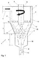
- FIG. 1 the hydrocyclone 1 according to the invention is shown. It consists of an inlet area 2 and an adjoining separation area 3.
- the inlet area 2 is here cylindrical.
- the separation region 3 consists of a conical section 15, which leads directly to the inlet region 2 adjacent to the conical portion 15 cylindrical portion 18.
- the diameter x of the cylindrical portion 18 is here 30 mm and the height (length of the portion 18 viewed in the axial direction) y is 40 mm here.
- This discharge pipe 8 can act as a holder for another nozzle, or even embody the discharge nozzle itself.
- a feed pulp 6 is fed to the hydrocyclone 1.
- the feed pulp 6 may be, for example, a gypsum suspension.
- the upper-stream nozzle 9 which protrudes axially in the form of a dip tube into the interior of the hydrocyclone 1, the specific lighter or finer-grained fraction can be discharged as the upper reaches 12.
- the hydrocyclone 1 also has a further inlet 5 (in FIG Fig. 2 shown) for the barrier fluid flow 7, which is also supplied here tangentially to the inlet region 2.
- the barrier fluid 7 is, for example, water, alcohol or oil.
- the barrier fluid stream 7 and the feed pulp 6 are fed to the hydrocyclone 1 separately and separated in the hydrocyclone 1 by the blade 10 from each other.
- the lamella 10 is, for example, a cylindrical, thin-walled metal component.
- the pure barrier fluid flow 7 meets at the lower end 13 of the blade 10 with the actual suspension flow (Aufgabetrübe 6) together. This takes place as soon as the flows from the barrier fluid 7 and the feed pulp 6 are stably formed.
- the distance z from the lower end of the blade 10 to the transition from the conical portion 15 to the cylindrical portion 18 is less than 100 mm here.
- the lamella 10 here has equalization openings 17, which constitute a connection between the feed pulp 6 and the barrier fluid flow 7, which results in a pressure equalization between the barrier fluid 7 and the suspension 6. These compensation holes are also conceivable in the region of the inlet 5.
- the flow arrows indicate that the barrier fluid flow 7 and the feed pulp 6 mix with one another as little as possible.
- the blocking fluid flow 7 thus forms a barrier fluid layer 7 towards the wall of the conical section 15.
- In the cylindrical portion 18 of the deposited coarse has enough space to move by means of rotary movement targeted direction Unterlaufaustragsrohr 8.
- this extension prevents the core flow breaks through into the actual underflow (11).
- the mouth opening 14 of the upper nozzle 9 ends here in the region below the end 13 of the blade 10th Depending on the respective volume fractions in the barrier fluid flow 7 and the feed pulp 6, the separation of the heavy fraction (coarse particles) will be more or less sharp.
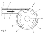
- FIG. 2 shows a cross-section through a hydrocyclone 1 according to the invention in the region of the inlet.
- the tangential inlet 4 for the feed pulp 6 and the tangential inlet 5 for the barrier fluid layer 7 can be easily recognized.
- These two inlets 4, 5 open substantially parallel into the inlet area second
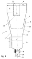
- Fig. 3 shows a further embodiment of the hydrocyclone invention 1.
- the diameter D1 of the inlet region here is 75 mm and the inner diameter D2 of the head nozzle is 25 mm.
- This hydrocyclone 1 has a cone-shaped lamella 10, which extends into the cone-shaped portion 15 of the separation region 3.
- the further inlet 5 for the supply of the barrier fluid 7 is located between the conical lamella 10 and the conical section 15 of the separation region 3.
- the adjacent to the conical section 15 cylindrical portion 18 here has a height y of 150 mm and a diameter x of 37 mm up. Below the cylindrical portion 18, the underflow discharge pipe 8 having an initial diameter d2 of 25 mm and a final diameter of 10 mm is disposed.
- the jump of the diameter in the underflow nozzle comes here by conditions, because here a nozzle 19 is inserted for the discharge of the lower run 11 in the Unterlaufaustragsrohr 8.
- the underflow nozzle may also have a uniform diameter of, for example, 10 mm.
- the dimensions given here refer to a hydrocyclone which has achieved very good results in the experimental plant, it is of course possible that deviating dimensions also achieve very good results.
Landscapes
- Physics & Mathematics (AREA)
- Fluid Mechanics (AREA)
- Geometry (AREA)
- Cyclones (AREA)
Abstract
Description
- Den Gegenstand dieser Erfindung bildet ein Hydrozyklon mit einem Zulaufbereich mit einem tangentialen Zulauf für eine Aufgabetrübe und einem weiteren an den Zulaufbereich anschließenden Abscheidebereich mit einem Unterlaufaustragsrohr zur Abfuhr von Schwerstoffen und einer Oberlaufdüse, die in Form eines Tauchrohres axial in das Innere des Hydrozyklons ragt. Im Bereich des tangentialen Zulaufs ist ein weiterer Zulauf zur Zufuhr eines Sperrfluidstromes vorgesehen, wobei das Sperrfluid und die Aufgabetrübe im Hydrozyklon vor ihrer Zusammenführung durch eine Lamelle voneinander getrennt sind.
- Ein Hydrozyklon besteht in der Regel aus einem zylindrischen Segment mit einem tangentialen Zulauf (Einlaufdüse) und einem daran anschließenden konischen Segment mit der Unterlauf- oder Apexdüse. Der Vortex-Finder bzw. die Oberlaufdüse ragt in Form eines Tauchrohres axial von oben in das Innere des Zyklons.
- Die Bezeichnungen "oben" und "unten" gehen in der vorliegenden Beschreibung vom Oberlauf (spezifisch leichtere und/oder kleinkörnigere Fraktion) und vom Unterlauf (spezifisch schwerere und/oder gröbere Fraktion) aus. Die tatsächliche Positionierung des Hydrozyklons ist davon jedoch weitestgehend unabhängig, so werden häufig auch horizontal eingebaute Hydrozyklone verwendet.
- Hydrozyklone sind Trennaggregate, die Feststoffgemische basierend auf unterschiedlichen Sinkgeschwindigkeiten zu trennen vermögen. Dabei ist von keiner vollständigen Trennung der Fraktionen auszugehen, vielmehr sind große Unterschiede in der Sinkgeschwindigkeit mit stark unterschiedlichen Wahrscheinlichkeiten belegt, in den jeweiligen Grob- oder Feinstoffabzug zu gelangen.
- Die Trübe wird dabei in der Regel dem Zyklon Kopfstück tangential zugeführt, dort auf eine abwärts gerichtete Kreisbahn gezwungen und durch die konische Verjüngung des Zyklonunterteils auf der daraus resultierenden Abwärtsspirale beschleunigt. Diese Beschleunigung und die daraus resultierende Fliehkraft resultieren in einem starken Kraftfeld, welches alle spezifisch schwereren Partikel als das umgebende Fluid nach außen treibt, während alle leichteren Teilchen nach innen gefördert werden. Entlang der gesamten Abwärtsspirale erfolgt eine Ablösung der kernnahen Schichten in die nach oben gerichtete Oberlaufströmung. Der unten abgeführte, eingedickte Strom wird Unterlauf genannt, der nach oben abgeführte, wird als Ober- bzw. Überlauf bezeichnet.
- Naturgemäß beinhaltet die Oberlaufströmung deutlich weniger Feststoffe als die außenliegenden, nach unten gerichteten Strömungsfelder. Zudem besteht für Partikel mit sehr kleinen Sinkgeschwindigkeiten eine deutlich höhere Wahrscheinlichkeit in die Oberlaufströmung zu gelangen, als dies für grobkörnige Fraktionen der Fall ist, sodass es zu einer relativen Anreicherung an Feinstoffen (auf die Feststoffmasse bezogen) im Oberlauf kommt. Volumenbezogen (in mg/l) liegt der Fall allerdings genau umgekehrt, bezogen auf den abgeführten Volumenstrom weist der Oberlauf eine Feststoffabreicherung bei Feinfraktionen auf, sofern diese spezifisch schwerer als das Fluid sind.
- Es tritt also im Unterlauf eine (häufig ungewollte) Aufkonzentration von Feinstoffen, bezogen auf das abgezogene Fluidvolumen auf.
- Um dies zu unterbinden wurde ein einleitend erwähnter Waschwasserzyklon entwickelt, mit der Zielsetzung, mittels Lamelle eine Sperrwasserschicht (Sedimentationshilfsschicht) zu kreieren, die es Feinstoffen aufgrund der reduzierten Sedimentationsgeschwindigkeit erschwert in den nach unten abgeführten Bereich zu sedimentieren. Dieser spezielle Hydrozyklon ist in der
WO 2013/117342 beschrieben. - Bei diesem Hydrozyklon entstehen jedoch insbesondere im Bereich der Strömungsumkehr im Konusaustrittsbereich häufig instabile Zustände, die in einer starken Bewegung der im Kernbereich befindlichen Trombe resultieren und die solcherart eine Wiedervermischung von ursprünglich getrennten Fraktionen verursachen können. Zudem kann bei räumlicher Nähe der nach oben gerichteten Kernströmung (mit Feinstoffen) und der nach unten gerichteten, gewaschenen Unterlaufströmung ein Fehlaustrag einzelner Strömungsschichten erfolgen, was ebenfalls den Fehlkornaustrag erhöhen kann.
- Es hat sich außerdem gezeigt, dass insbesondere bei hohen Temperaturen der Aufgabetrübe ein vermehrter Fehlaustrag von "Kernströmung" in den Unterlauf erfolgt. Verstärkt wird das Problem durch die Zudosierung von Waschwasser, welches zudem zu einer deutlichen Verdünnung im Unterlauf führen kann.
- Der Erfindung liegt daher die Aufgabe zugrunde, einen mit Sperrfluidschicht arbeitenden Hydrozyklon derart zu verbessern, dass er leichter in stabilen Zuständen betrieben werden kann, wodurch der Fehlaustrag von Feinstoff bzw. Feinkorn im Unterlauf weiter verringert wird. Die Feinstoffe sollen also - bezogen auf die volumenbezogene Konzentration im Einlauf - im Unterlauf abgereichert werden.
- Gelöst wird diese Aufgabe durch einen Hydrozyklon gemäß Patentanspruch 1. Beim erfindungsgemäßen Hydrozyklon besteht der Abscheidebereich aus einem konischen Teilstück und aus einem daran anschließenden zylindrischen Teilstück oberhalb dem Unterlaufaustragsrohr.
- Dadurch wird der Abstand der Strömungsumkehr zum Unterlaufabzug vergrößert. Aufgabe des zylindrischen Teilstücks ist es, den abgesetzten Grobstoff konzentriert mittels Drehbewegung in einer definierten Bewegung zum Auslass hin zu bewegen, ohne der (instationären) Kernströmung eine Möglichkeit zu geben, in die Unterlaufdüse bzw. das Unterlaufaustragsrohr durchzuschlagen. Die zylindrische Verlängerung bietet somit eine Art "Feststoffpuffer", der eine beruhigte Abzugszone durch die konventionell angeordnete Austragsdüse bedingt.
- Zudem ermöglicht diese Erfindung die Verwendung einer größeren Unterlaufdüse, als in herkömmlichen Hydrozyklonen mit vergleichbaren Abzugsverhältnissen in Unter- und Oberlauf. Durch die Möglichkeit der Verwendung einer größeren Unterlaufdüse bzw. eines größeren Unterlaufaustragsrohrs erhöht sich auch die Betriebssicherheit, weil sich die Gefahr einer Verstopfung der Unterlaufdüse erheblich verringert.
- Gute Trennungsergebnisse werden erzielt, wenn der Durchmesser des zylindrischen Teilstücks kleiner als die Höhe des zylindrischen Teilstücks ist.
Es ist günstig, wenn der Durchmesser des zylindrischen Teilstücks zumindest 25 mm, vorzugsweise zumindest 30 mm, beträgt. - Vorzugsweise ist der Übergang vom konischen Teilstück zum zylindrischen Teilstück maximal 100 mm nach der Sperrfluidzuführung, also unterhalb des Lamellenendes angeordnet.
- Vorzugsweise ist die Lamelle im Wesentlichen zylinderförmig oder konisch ausgebildet. Sie kann sich dabei im Zulaufbereich bzw. im zylindrischen Segment vom Einlaufbereich der Sperrfluidströmung bis zum Übergang zum konischen Abscheidebereich erstrecken oder im konischen Bereich befestigt sein. Dadurch verbleibt genug Zeit, dass sich sowohl in der Sperrfluidschicht als auch in der Aufgabetrübe eine stabile kreisförmige Strömung ausbilden kann.
- Es ist günstig, wenn die Lamelle an ihrem unteren Ende spitz zusammenläuft bzw. möglichst dünn ausgeführt ist, sodass der Sperrfluidstrom und die Aufgabetrübe möglichst wirbelfrei zusammenführbar sind. Die beiden Strömungen sollen auch unterhalb der Lamelle möglichst getrennt voneinander weiterströmen.
- In einer günstigen Ausführungsform erstreckt sich die Mündungsöffnung der Oberlaufdüse bis in den Bereich in dem die Sperrfluidströmung und die Aufgabetrübe gemeinsam weitergeführt werden.
- Die Lamelle kann auch Ausgleichsöffnungen aufweisen, die eine Verbindung zwischen der Aufgabetrübe und der Sperrfluidströmung darstellen, dadurch kommt es zu einem Druckausgleich zwischen Sperrfluid und Suspension, bevor die beiden Schichten aufeinander treffen. Idealerweise ist dabei das Sperrfluid immer mit einem etwas höheren Druck beaufschlagt, als die Suspension.
- Im Folgenden wird der erfindungsgemäße Hydrozyklon anhand von drei Zeichnungen beschrieben. Es zeigen:
-
Fig. 1 einen schematischen Längsschnitt durch ein Ausführungsbeispiel des erfindungsgemäßen Hydrozyklons; -
Fig. 2 einen Querschnitt im Bereich des Einlaufs durch den erfindungsgemäßen Hydrozyklon; -
Fig. 3 einen schematischen Längsschnitt durch ein weiteres Ausführungsbeispiel des erfindungsgemäßen Hydrozyklons; - Gleiche Bezugszeichen in den Figuren bezeichnen jeweils gleiche Bauteile oder Stoffströme.
InFigur 1 ist der erfindungsgemäße Hydrozyklon 1 dargestellt. Er besteht aus einem Zulaufbereich 2 und aus einem daran anschließenden Abscheidebereich 3. Der Zulaufbereich 2 ist hier zylinderförmig ausgebildet. Der Abscheidebereich 3 besteht aus einem konischen Teilstück 15, das direkt an den Zulaufbereich 2 angrenzt, und aus einem an das konische Teilstück 15 angrenzenden zylindrischen Teilstück 18. Der Durchmesser x des zylindrischen Teilstücks 18 beträgt hier 30 mm und dessen Höhe (Länge des Teilstücks 18 in axialer Richtung betrachtet) y beträgt hier 40 mm. An das zylindrische Teilstück 18 schließt nach einer Querschnittsverengung eine Unterlaufaustragsrohr 8 zur Abfuhr von Grobstoffen bzw. Grobkorn an. Dieses Austragsrohr 8 kann als Halterung einer weiteren Düse fungieren, oder aber bereits die Austragsdüse selbst verkörpern. - Über den tangentialen Zulauf 4 wird eine Aufgabetrübe 6 dem Hydrozyklon 1 zugeführt. Bei der Aufgabetrübe 6 kann es sich beispielsweise um eine Gipssuspension handeln.
Durch die Oberlaufdüse 9, die in Form eines Tauchrohres axial in das Innere des Hydrozyklons 1 ragt, kann die spezifisch leichtere bzw. feinkörnigere Fraktion als Oberlauf 12 abgeführt werden. - Neben dem tangentialen Zulauf 4 weist der Hydrozyklon 1 auch einen weiteren Zulauf 5 (in
Fig. 2 dargestellt) für den Sperrfluidstrom 7 auf, der hier ebenfalls tangential dem Zulaufbereich 2 zugeführt wird. Beim Sperrfluid 7 handelt es sich beispielsweise um Wasser, Alkohol oder Öl. Der Sperrfluidstrom 7 und die Aufgabetrübe 6 werden dem Hydrozyklon 1 getrennt zugeführt und im Hydrozyklon 1 durch die Lamelle 10 voneinander getrennt. Bei der Lamelle 10 handelt es sich beispielsweise um ein zylinderförmiges, dünnwandiges Bauteil aus Metall. Die reine Sperrfluidströmung 7 trifft am unteren Ende 13 der Lamelle 10 mit der eigentlichen Suspensionsströmung (Aufgabetrübe 6) zusammen. Dies erfolgt, sobald die Strömungen vom Sperrfluid 7 und der Aufgabetrübe 6 stabil ausgebildet sind. Der Abstand z vom unteren Ende der Lamelle 10 zum Übergang vom konischen Teilstück 15 zum zylindrischen Teilstück 18 beträgt hier weniger als 100 mm. - Nach der Zusammenführung der beiden Volumenströme 6, 7 stellt sich eine Sedimentationsbewegung von Schwerteilen (Grobstoffen) durch die Sperrschicht 7 ein. Dadurch kommt es zu einer Abreicherung der Feinstoffe im Unterlauf 11. Im konischen Abscheidebereich 3 erfolgt die Strömungsführung wie in konventionellen Hydrozyklonen.
Die Lamelle 10 weist hier Ausgleichsöffnungen 17 auf, die eine Verbindung zwischen der Aufgabetrübe 6 und der Sperrfluidströmung 7 darstellen, dadurch kommt es zu einem Druckausgleich zwischen Sperrfluid 7 und Suspension 6. Diese Ausgleichslöcher sind auch im Bereich des Zulaufs 5 denkbar. - Durch die Strömungspfeile wird angedeutet, dass sich die Sperrfluidströmung 7 und die Aufgabetrübe 6 möglichst wenig miteinander vermischen. Die Sperrfluidströmung 7 bildet also zur Wand des konusförmigen Teilstücks 15 hin eine Sperrfluidschicht 7 aus.
Im zylindrischen Teilstück 18 hat der abgesetzte Grobstoff genügend Platz, um sich mittels Drehbewegung gezielt Richtung Unterlaufaustragsrohr 8 zu bewegen. Außerdem verhindert diese Verlängerung, dass die Kernströmung in den eigentlichen Unterlauf (11) durchschlägt. - Die Mündungsöffnung 14 der Oberlaufdüse 9 endet hier im Bereich unterhalb des Endes 13 der Lamelle 10.
Je nach den jeweiligen Volumenanteilen in der Sperrfluidströmung 7 und der Aufgabetrübe 6 wird die Abscheidung der Schwerteilfraktion (Grobstoffe) mehr oder weniger scharf sein. -
Figur 2 stellt einen Querschnitt durch einen erfindungsgemäßen Hydrozyklon 1 im Bereich des Einlaufs dar. Hierbei erkennt man gut den tangentialen Zulauf 4 für die Aufgabetrübe 6 und den tangentialen Zulauf 5 für die Sperrfluidschicht 7. Diese beiden Zuläufe 4, 5 münden hier im Wesentlichen parallel in den Zulaufbereich 2. -
Fig. 3 zeigt ein weiteres Ausführungsbeispiel des erfindungsgemäßen Hydrozyklons 1. Der Durchmesser D1 des Einlaufbereiches beträgt hier 75 mm und der Innendurchmesser D2 der Oberlaufdüse liegt bei 25 mm. Dieser Hydrozyklon 1 weist eine konusförmige Lamelle 10 auf, die sich bis in das konusförmige Teilstück 15 des Abscheidebereichs 3 erstreckt. Der weitere Zulauf 5 für die Zufuhr des Sperrfluids 7 befindet sich zwischen der konischen Lamelle 10 und dem konischen Teilstück 15 des Abscheidebereiches 3. Das an das konische Teilstück 15 angrenzende zylindrische Teilstück 18 weist hier eine Höhe y von 150 mm und einen Durchmesser x von 37 mm auf. Unterhalb des zylindrischen Teilstücks 18 ist das Unterlaufaustragsrohr 8 mit einem anfänglichen Durchmesser d2 von 25 mm und einem letztendlichen Durchmesser von 10 mm angeordnet. Der Sprung des Durchmessers in der Unterlaufdüse kommt hier dadurch zu Stande, weil hier eine Düse 19 zur Abfuhr des Unterlaufs 11 in das Unterlaufaustragsrohr 8 gesteckt ist. Natürlich kann die Unterlaufdüse auch einen einheitlichen Durchmesser von beispielsweise 10 mm aufweisen. Die hier angeführten Maße beziehen sich auf einen Hydrozyklon, der in der Versuchsanlage sehr gute Resultate erzielt hat, selbstverständlich ist es möglich, dass davon abweichende Maße ebenfalls sehr gute Ergebnisse erzielen.
Claims (10)
- Hydrozyklon (1) mit einem Zulaufbereich (2) mit einem tangentialen Zulauf (4) für eine Aufgabetrübe (6) und einem weiteren an den Zulaufbereich (2) anschließenden Abscheidebereich (3) mit einem Unterlaufaustragsrohr (8) zur Abfuhr von Schwerstoffen bzw. Grobkorn, wobei eine Oberlaufdüse (9) in Form eines Tauchrohres axial in das Innere des Hydrozyklons (1) ragt, und im Bereich des tangentialen Zulaufs (4) zumindest ein weiterer Zulauf (5) zur Zufuhr eines Sperrfluidstromes (7) vorgesehen ist, wobei das Sperrfluid (7) und die Aufgabetrübe (6) im Hydrozyklon (1) zusammenführbar sind und dass sie vor ihrer Zusammenführung durch eine Lamelle (10) voneinander getrennt sind, dadurch gekennzeichnet, dass der Abscheidebereich (3) aus einem konischen Teilstück (15) und aus einem daran anschließenden zylindrischen Teilstück (18) oberhalb des Unterlaufaustragsrohres (8) besteht.
- Hydrozyklon (1) nach Anspruch 1, dadurch gekennzeichnet, dass der Durchmesser (x) des zylindrischen Teilstücks (18) kleiner als die Höhe (y) des zylindrischen Teilstücks (18) ist.
- Hydrozyklon (1) nach Anspruch 1 oder 2, dadurch gekennzeichnet, dass der Übergang vom konischen Teilstück (15) zum zylindrischen Teilstück (18) maximal 100 mm nach der Sperrfluidzuführung angeordnet ist.
- Hydrozyklon (1) nach einem der Ansprüche 1 bis 3, dadurch gekennzeichnet, dass der Durchmesser (x) des zylindrischen Teilstücks (18) zumindest 25 mm, vorzugsweise zumindest 30 mm, beträgt.
- Hydrozyklon (1) nach einem der Ansprüche 1 bis 4, dadurch gekennzeichnet, dass die Lamelle (10) im Wesentlichen zylindrisch ist.
- Hydrozyklon (1) nach einem der Ansprüche 1 bis 4, dadurch gekennzeichnet, dass die Lamelle (10) im Wesentlichen konisch ist.
- Hydrozyklon (1) nach einem der Ansprüche 1 bis 6, dadurch gekennzeichnet, dass sich die Lamelle (10) im Zulaufbereich (2) bis zum Übergang zum Abscheidebereich (3) erstreckt.
- Hydrozyklon (1) nach einem der Ansprüche 1 bis 6, dadurch gekennzeichnet, dass sich die Lamelle (10) bis in den Abscheidebereich (3) erstreckt.
- Hydrozyklon (1) nach einem der Ansprüche 1 bis 8, dadurch gekennzeichnet, dass sich die Mündungsöffnung (14) der Oberlaufdüse (9) bis in den Bereich erstreckt, in dem die Sperrfluidströmung (7) und die Aufgabetrübe (6) gemeinsam weitergeführt werden.
- Hydrozyklon (1) nach einem der Ansprüche 1 bis 9, dadurch gekennzeichnet, dass die Lamelle (10) an ihrem unteren Ende (13) spitz zusammenläuft, sodass der Sperrfluidstrom (7) und die Aufgabetrübe (6) möglichst wirbelfrei zusammenführbar sind.
Priority Applications (2)
| Application Number | Priority Date | Filing Date | Title |
|---|---|---|---|
| RS20211440A RS62791B1 (sr) | 2015-08-21 | 2016-07-20 | Hidrociklon sa smanjenjem finih materijala u otoku ciklona |
| PL16180341T PL3132856T3 (pl) | 2015-08-21 | 2016-07-20 | Hydrocyklon z redukcją materiału drobnoziarnistego w biegu dolnym cyklonu |
Applications Claiming Priority (1)
| Application Number | Priority Date | Filing Date | Title |
|---|---|---|---|
| ATA557/2015A AT516856B1 (de) | 2015-08-21 | 2015-08-21 | Hydrozyklon mit Feinstoffabreicherung im Zyklonunterlauf |
Publications (2)
| Publication Number | Publication Date |
|---|---|
| EP3132856A1 true EP3132856A1 (de) | 2017-02-22 |
| EP3132856B1 EP3132856B1 (de) | 2021-09-01 |
Family
ID=56497656
Family Applications (1)
| Application Number | Title | Priority Date | Filing Date |
|---|---|---|---|
| EP16180341.6A Not-in-force EP3132856B1 (de) | 2015-08-21 | 2016-07-20 | Hydrozyklon mit feinstoffabreicherung im zyklonunterlauf |
Country Status (5)
| Country | Link |
|---|---|
| US (1) | US9884325B2 (de) |
| EP (1) | EP3132856B1 (de) |
| AT (1) | AT516856B1 (de) |
| PL (1) | PL3132856T3 (de) |
| RS (1) | RS62791B1 (de) |
Families Citing this family (9)
| Publication number | Priority date | Publication date | Assignee | Title |
|---|---|---|---|---|
| US9858925B2 (en) * | 2009-06-05 | 2018-01-02 | Apple Inc. | Using context information to facilitate processing of commands in a virtual assistant |
| US11577366B2 (en) * | 2016-12-12 | 2023-02-14 | Omax Corporation | Recirculation of wet abrasive material in abrasive waterjet systems and related technology |
| WO2019232195A1 (en) | 2018-05-30 | 2019-12-05 | Chemtreat, Inc. | Flue gas desulfurization system and method for performing flue gas desulfurization |
| CN108643964B (zh) * | 2018-07-10 | 2023-12-22 | 长沙矿山研究院有限责任公司 | 一种分级尾砂充填系统中的旋流器底流消能器及消能方法 |
| CN111804447B (zh) * | 2020-07-23 | 2024-11-05 | 唐山安丰智能科技有限公司 | 一种用于精选机上的旋流布料装置 |
| US12002451B1 (en) * | 2021-07-01 | 2024-06-04 | Amazon Technologies, Inc. | Automatic speech recognition |
| CN113369027A (zh) * | 2021-07-28 | 2021-09-10 | 东北大学 | 多级旋流分离柱 |
| CN117483093B (zh) * | 2023-12-13 | 2026-07-21 | 山东理工大学 | 一种内循环强化重力分选设备 |
| WO2026130661A1 (de) * | 2024-12-17 | 2026-06-25 | Ifec Hp-Tech Gmbh | Hydrodynamischer flüssigkeitsaufbereitungsreaktor |
Citations (4)
| Publication number | Priority date | Publication date | Assignee | Title |
|---|---|---|---|---|
| FR1147973A (fr) * | 1955-03-10 | 1957-12-02 | Horace Freeman | Perfectionnements à l'épuration des suspensions de pâte à papier ou des liquides analogues |
| AU2504584A (en) * | 1983-02-24 | 1984-08-30 | Conoco Specialty Products Inc. | Improved outlet for cyclone separators |
| JPH10151371A (ja) * | 1996-11-26 | 1998-06-09 | Ube Ind Ltd | サイクロン |
| WO2013117342A1 (de) * | 2012-02-10 | 2013-08-15 | Andritz Energy & Environment Gmbh | Hydrozyklon mit feinstoffabreicherung im zyklonunterlauf |
Family Cites Families (16)
| Publication number | Priority date | Publication date | Assignee | Title |
|---|---|---|---|---|
| US1509915A (en) * | 1922-11-09 | 1924-09-30 | Albert H Stebbins | Concentrator |
| NL284340A (de) * | 1961-10-16 | |||
| US3331193A (en) * | 1964-03-23 | 1967-07-18 | Bauer Bros Co | Cyclonic separator |
| SE357309B (de) * | 1969-03-21 | 1973-06-25 | Celleco Ab | |
| US3507397A (en) * | 1969-04-09 | 1970-04-21 | William R Robinson | Hydrocyclone unit |
| SE407751B (sv) * | 1976-03-26 | 1979-04-23 | Celleco Ab | Anordning vid en hydrocyklon |
| US4623458A (en) * | 1983-07-19 | 1986-11-18 | Hakola Gordon R | Quick release expendable apex apparatus with bonded liner |
| US4652363A (en) * | 1984-11-01 | 1987-03-24 | Miller Francis G | Dual feed hydrocyclone and method of separating aqueous slurry |
| US4696737A (en) * | 1986-02-28 | 1987-09-29 | The Bauer Bros. Co. | Fiber recovery elutriating hydrocyclone |
| JPH01502886A (ja) * | 1986-04-23 | 1989-10-05 | コノコ スペシャルティ プロダクツ インコーポレイティド | サイクロン セパレータ |
| US4969934A (en) * | 1989-08-04 | 1990-11-13 | The United States Of America As Represented By The United States Department Of Energy | Method for improved gas-solids separation |
| EP1385631B1 (de) * | 2001-03-26 | 2009-08-19 | Weir Minerals Australia Ltd | Verbesserungen bei hydrozyklonen und diese betreffende verbesserungen |
| CL2003001757A1 (es) * | 2003-08-29 | 2005-01-21 | Vulco Sa | Cabezal de entrada para hidrociclon, en el cual la altura del buscador de vortice, es una fraccion de la altura de la entrada de alimentacion, la cual es rectangular, donde dicha entrada tiene un primer sector que forma una voluta horizontal, y un se |
| US7185765B2 (en) * | 2003-11-19 | 2007-03-06 | Hakola Gordon R | Cyclone with in-situ replaceable liner system and method for accomplishing same |
| IL178234A (en) * | 2006-09-21 | 2013-05-30 | Vortex Ecological Technologies Ltd | Cyclone vortex separator |
| AT512479B1 (de) * | 2012-02-10 | 2013-11-15 | Andritz Energy & Environment Gmbh | Verfahren zur feinstoffreduktion im rea-gips |
-
2015
- 2015-08-21 AT ATA557/2015A patent/AT516856B1/de not_active IP Right Cessation
-
2016
- 2016-07-20 EP EP16180341.6A patent/EP3132856B1/de not_active Not-in-force
- 2016-07-20 RS RS20211440A patent/RS62791B1/sr unknown
- 2016-07-20 PL PL16180341T patent/PL3132856T3/pl unknown
- 2016-08-08 US US15/230,583 patent/US9884325B2/en not_active Expired - Fee Related
Patent Citations (4)
| Publication number | Priority date | Publication date | Assignee | Title |
|---|---|---|---|---|
| FR1147973A (fr) * | 1955-03-10 | 1957-12-02 | Horace Freeman | Perfectionnements à l'épuration des suspensions de pâte à papier ou des liquides analogues |
| AU2504584A (en) * | 1983-02-24 | 1984-08-30 | Conoco Specialty Products Inc. | Improved outlet for cyclone separators |
| JPH10151371A (ja) * | 1996-11-26 | 1998-06-09 | Ube Ind Ltd | サイクロン |
| WO2013117342A1 (de) * | 2012-02-10 | 2013-08-15 | Andritz Energy & Environment Gmbh | Hydrozyklon mit feinstoffabreicherung im zyklonunterlauf |
Also Published As
| Publication number | Publication date |
|---|---|
| US20170050191A1 (en) | 2017-02-23 |
| US9884325B2 (en) | 2018-02-06 |
| RS62791B1 (sr) | 2022-02-28 |
| PL3132856T3 (pl) | 2022-01-24 |
| AT516856A4 (de) | 2016-09-15 |
| EP3132856B1 (de) | 2021-09-01 |
| AT516856B1 (de) | 2016-09-15 |
Similar Documents
| Publication | Publication Date | Title |
|---|---|---|
| AT516856B1 (de) | Hydrozyklon mit Feinstoffabreicherung im Zyklonunterlauf | |
| AT511837B1 (de) | Hydrozyklon mit feinstoffabreicherung im zyklonunterlauf | |
| DE2148422C3 (de) | Hydrozyklon | |
| EP2812122B1 (de) | Verfahren zur feinstoffreduktion im rea-gips | |
| DE1092445B (de) | Vorrichtung zum Ausscheiden unerwuenschter Teilchen aus Fluessigkeiten | |
| DE3650237T2 (de) | Gegenläufiges Hydrozyklon zum Abtrennen von leichten Verunreinigungen aus einer Fasergutsuspension. | |
| EP3541527B1 (de) | Hydrozyklonanordnung | |
| DE942081C (de) | Vorrichtung und Verfahren zum Klassieren von festen Stoffen in einem Hydrozyklon | |
| DE2147549A1 (de) | Sichter fuer feinkoerniges gut | |
| EP1799903B1 (de) | Verfahren zum fraktionieren einer wässrigen papierfasersuspension sowie hydrozyklon zur durchführung des verfahrens | |
| WO1997016253A2 (de) | Vorrichtung zum abscheiden von leichtstoffen aus sand und kies | |
| DE1517890A1 (de) | Zentrifugalabschneider | |
| DE19508430A1 (de) | Hydrozyklon | |
| EP3524357B1 (de) | Abscheidevorrichtung | |
| AT518392B1 (de) | Hydrozyklon mit speziellem Unterlaufaustragsrohr | |
| DE1442501B2 (de) | Hydrocyklon | |
| DE899931C (de) | Verfahren und Vorrichtung zur Klassierung von Gemischen nach Fallgeschwindigkeit im aufsteigenden Fluessigkeitsstrom | |
| AT521979B1 (de) | Vorrichtung zum Filtern von Partikeln | |
| DE1442501C (de) | Hydrocyklon | |
| DE102017128560B3 (de) | Vorrichtung zum Abscheiden von Sinkstoffen aus Flüssigkeiten, Reinigungseinrichtung und Verfahren zum Abscheiden von Sinkstoffen | |
| DE1442375C (de) | Hydrozyklonabscheider | |
| AT89437B (de) | Abscheider für Kohlen, Ton, Erze u. dgl. | |
| EP4370743A1 (de) | Hydrozyklone-anordnung zum zentrifugalabscheiden von feststoffen aus einer suspension | |
| DE102024113569A1 (de) | Unterlauf-Austragsvorrichtung und Hydrozyklon mit einer solchen Unterlauf-Austragsvorrichtung | |
| WO1994021964A1 (de) | Wirbelbett |
Legal Events
| Date | Code | Title | Description |
|---|---|---|---|
| PUAI | Public reference made under article 153(3) epc to a published international application that has entered the european phase |
Free format text: ORIGINAL CODE: 0009012 |
|
| STAA | Information on the status of an ep patent application or granted ep patent |
Free format text: STATUS: THE APPLICATION HAS BEEN PUBLISHED |
|
| AK | Designated contracting states |
Kind code of ref document: A1 Designated state(s): AL AT BE BG CH CY CZ DE DK EE ES FI FR GB GR HR HU IE IS IT LI LT LU LV MC MK MT NL NO PL PT RO RS SE SI SK SM TR |
|
| AX | Request for extension of the european patent |
Extension state: BA ME |
|
| STAA | Information on the status of an ep patent application or granted ep patent |
Free format text: STATUS: REQUEST FOR EXAMINATION WAS MADE |
|
| 17P | Request for examination filed |
Effective date: 20170725 |
|
| RBV | Designated contracting states (corrected) |
Designated state(s): AL AT BE BG CH CY CZ DE DK EE ES FI FR GB GR HR HU IE IS IT LI LT LU LV MC MK MT NL NO PL PT RO RS SE SI SK SM TR |
|
| GRAP | Despatch of communication of intention to grant a patent |
Free format text: ORIGINAL CODE: EPIDOSNIGR1 |
|
| STAA | Information on the status of an ep patent application or granted ep patent |
Free format text: STATUS: GRANT OF PATENT IS INTENDED |
|
| RIC1 | Information provided on ipc code assigned before grant |
Ipc: B04C 9/00 20060101ALI20210401BHEP Ipc: B04C 5/103 20060101ALI20210401BHEP Ipc: B04C 5/14 20060101ALI20210401BHEP Ipc: B04C 5/081 20060101ALI20210401BHEP Ipc: B04C 5/04 20060101AFI20210401BHEP |
|
| INTG | Intention to grant announced |
Effective date: 20210428 |
|
| GRAS | Grant fee paid |
Free format text: ORIGINAL CODE: EPIDOSNIGR3 |
|
| GRAA | (expected) grant |
Free format text: ORIGINAL CODE: 0009210 |
|
| STAA | Information on the status of an ep patent application or granted ep patent |
Free format text: STATUS: THE PATENT HAS BEEN GRANTED |
|
| AK | Designated contracting states |
Kind code of ref document: B1 Designated state(s): AL AT BE BG CH CY CZ DE DK EE ES FI FR GB GR HR HU IE IS IT LI LT LU LV MC MK MT NL NO PL PT RO RS SE SI SK SM TR |
|
| REG | Reference to a national code |
Ref country code: GB Ref legal event code: FG4D Free format text: NOT ENGLISH |
|
| REG | Reference to a national code |
Ref country code: CH Ref legal event code: EP Ref country code: AT Ref legal event code: REF Ref document number: 1425647 Country of ref document: AT Kind code of ref document: T Effective date: 20210915 |
|
| REG | Reference to a national code |
Ref country code: DE Ref legal event code: R096 Ref document number: 502016013738 Country of ref document: DE |
|
| REG | Reference to a national code |
Ref country code: IE Ref legal event code: FG4D Free format text: LANGUAGE OF EP DOCUMENT: GERMAN |
|
| REG | Reference to a national code |
Ref country code: SE Ref legal event code: TRGR |
|
| REG | Reference to a national code |
Ref country code: LT Ref legal event code: MG9D |
|
| REG | Reference to a national code |
Ref country code: NL Ref legal event code: MP Effective date: 20210901 |
|
| PG25 | Lapsed in a contracting state [announced via postgrant information from national office to epo] |
Ref country code: ES Free format text: LAPSE BECAUSE OF FAILURE TO SUBMIT A TRANSLATION OF THE DESCRIPTION OR TO PAY THE FEE WITHIN THE PRESCRIBED TIME-LIMIT Effective date: 20210901 Ref country code: FI Free format text: LAPSE BECAUSE OF FAILURE TO SUBMIT A TRANSLATION OF THE DESCRIPTION OR TO PAY THE FEE WITHIN THE PRESCRIBED TIME-LIMIT Effective date: 20210901 Ref country code: NO Free format text: LAPSE BECAUSE OF FAILURE TO SUBMIT A TRANSLATION OF THE DESCRIPTION OR TO PAY THE FEE WITHIN THE PRESCRIBED TIME-LIMIT Effective date: 20211201 Ref country code: LT Free format text: LAPSE BECAUSE OF FAILURE TO SUBMIT A TRANSLATION OF THE DESCRIPTION OR TO PAY THE FEE WITHIN THE PRESCRIBED TIME-LIMIT Effective date: 20210901 Ref country code: BG Free format text: LAPSE BECAUSE OF FAILURE TO SUBMIT A TRANSLATION OF THE DESCRIPTION OR TO PAY THE FEE WITHIN THE PRESCRIBED TIME-LIMIT Effective date: 20211201 Ref country code: HR Free format text: LAPSE BECAUSE OF FAILURE TO SUBMIT A TRANSLATION OF THE DESCRIPTION OR TO PAY THE FEE WITHIN THE PRESCRIBED TIME-LIMIT Effective date: 20210901 |
|
| PG25 | Lapsed in a contracting state [announced via postgrant information from national office to epo] |
Ref country code: LV Free format text: LAPSE BECAUSE OF FAILURE TO SUBMIT A TRANSLATION OF THE DESCRIPTION OR TO PAY THE FEE WITHIN THE PRESCRIBED TIME-LIMIT Effective date: 20210901 Ref country code: GR Free format text: LAPSE BECAUSE OF FAILURE TO SUBMIT A TRANSLATION OF THE DESCRIPTION OR TO PAY THE FEE WITHIN THE PRESCRIBED TIME-LIMIT Effective date: 20211202 |
|
| PG25 | Lapsed in a contracting state [announced via postgrant information from national office to epo] |
Ref country code: IS Free format text: LAPSE BECAUSE OF FAILURE TO SUBMIT A TRANSLATION OF THE DESCRIPTION OR TO PAY THE FEE WITHIN THE PRESCRIBED TIME-LIMIT Effective date: 20220101 Ref country code: SM Free format text: LAPSE BECAUSE OF FAILURE TO SUBMIT A TRANSLATION OF THE DESCRIPTION OR TO PAY THE FEE WITHIN THE PRESCRIBED TIME-LIMIT Effective date: 20210901 Ref country code: SK Free format text: LAPSE BECAUSE OF FAILURE TO SUBMIT A TRANSLATION OF THE DESCRIPTION OR TO PAY THE FEE WITHIN THE PRESCRIBED TIME-LIMIT Effective date: 20210901 Ref country code: RO Free format text: LAPSE BECAUSE OF FAILURE TO SUBMIT A TRANSLATION OF THE DESCRIPTION OR TO PAY THE FEE WITHIN THE PRESCRIBED TIME-LIMIT Effective date: 20210901 Ref country code: PT Free format text: LAPSE BECAUSE OF FAILURE TO SUBMIT A TRANSLATION OF THE DESCRIPTION OR TO PAY THE FEE WITHIN THE PRESCRIBED TIME-LIMIT Effective date: 20220103 Ref country code: NL Free format text: LAPSE BECAUSE OF FAILURE TO SUBMIT A TRANSLATION OF THE DESCRIPTION OR TO PAY THE FEE WITHIN THE PRESCRIBED TIME-LIMIT Effective date: 20210901 Ref country code: EE Free format text: LAPSE BECAUSE OF FAILURE TO SUBMIT A TRANSLATION OF THE DESCRIPTION OR TO PAY THE FEE WITHIN THE PRESCRIBED TIME-LIMIT Effective date: 20210901 Ref country code: CZ Free format text: LAPSE BECAUSE OF FAILURE TO SUBMIT A TRANSLATION OF THE DESCRIPTION OR TO PAY THE FEE WITHIN THE PRESCRIBED TIME-LIMIT Effective date: 20210901 Ref country code: AL Free format text: LAPSE BECAUSE OF FAILURE TO SUBMIT A TRANSLATION OF THE DESCRIPTION OR TO PAY THE FEE WITHIN THE PRESCRIBED TIME-LIMIT Effective date: 20210901 |
|
| REG | Reference to a national code |
Ref country code: DE Ref legal event code: R097 Ref document number: 502016013738 Country of ref document: DE |
|
| PLBE | No opposition filed within time limit |
Free format text: ORIGINAL CODE: 0009261 |
|
| STAA | Information on the status of an ep patent application or granted ep patent |
Free format text: STATUS: NO OPPOSITION FILED WITHIN TIME LIMIT |
|
| PG25 | Lapsed in a contracting state [announced via postgrant information from national office to epo] |
Ref country code: IT Free format text: LAPSE BECAUSE OF FAILURE TO SUBMIT A TRANSLATION OF THE DESCRIPTION OR TO PAY THE FEE WITHIN THE PRESCRIBED TIME-LIMIT Effective date: 20210901 Ref country code: DK Free format text: LAPSE BECAUSE OF FAILURE TO SUBMIT A TRANSLATION OF THE DESCRIPTION OR TO PAY THE FEE WITHIN THE PRESCRIBED TIME-LIMIT Effective date: 20210901 |
|
| 26N | No opposition filed |
Effective date: 20220602 |
|
| PG25 | Lapsed in a contracting state [announced via postgrant information from national office to epo] |
Ref country code: SI Free format text: LAPSE BECAUSE OF FAILURE TO SUBMIT A TRANSLATION OF THE DESCRIPTION OR TO PAY THE FEE WITHIN THE PRESCRIBED TIME-LIMIT Effective date: 20210901 |
|
| PG25 | Lapsed in a contracting state [announced via postgrant information from national office to epo] |
Ref country code: MC Free format text: LAPSE BECAUSE OF FAILURE TO SUBMIT A TRANSLATION OF THE DESCRIPTION OR TO PAY THE FEE WITHIN THE PRESCRIBED TIME-LIMIT Effective date: 20210901 |
|
| REG | Reference to a national code |
Ref country code: CH Ref legal event code: PL |
|
| GBPC | Gb: european patent ceased through non-payment of renewal fee |
Effective date: 20220720 |
|
| REG | Reference to a national code |
Ref country code: BE Ref legal event code: MM Effective date: 20220731 |
|
| PG25 | Lapsed in a contracting state [announced via postgrant information from national office to epo] |
Ref country code: LU Free format text: LAPSE BECAUSE OF NON-PAYMENT OF DUE FEES Effective date: 20220720 Ref country code: LI Free format text: LAPSE BECAUSE OF NON-PAYMENT OF DUE FEES Effective date: 20220731 Ref country code: FR Free format text: LAPSE BECAUSE OF NON-PAYMENT OF DUE FEES Effective date: 20220731 Ref country code: CH Free format text: LAPSE BECAUSE OF NON-PAYMENT OF DUE FEES Effective date: 20220731 |
|
| PG25 | Lapsed in a contracting state [announced via postgrant information from national office to epo] |
Ref country code: GB Free format text: LAPSE BECAUSE OF NON-PAYMENT OF DUE FEES Effective date: 20220720 Ref country code: BE Free format text: LAPSE BECAUSE OF NON-PAYMENT OF DUE FEES Effective date: 20220731 |
|
| PG25 | Lapsed in a contracting state [announced via postgrant information from national office to epo] |
Ref country code: IE Free format text: LAPSE BECAUSE OF NON-PAYMENT OF DUE FEES Effective date: 20220720 |
|
| REG | Reference to a national code |
Ref country code: AT Ref legal event code: MM01 Ref document number: 1425647 Country of ref document: AT Kind code of ref document: T Effective date: 20220720 |
|
| PG25 | Lapsed in a contracting state [announced via postgrant information from national office to epo] |
Ref country code: AT Free format text: LAPSE BECAUSE OF NON-PAYMENT OF DUE FEES Effective date: 20220720 |
|
| PGFP | Annual fee paid to national office [announced via postgrant information from national office to epo] |
Ref country code: TR Payment date: 20230717 Year of fee payment: 8 |
|
| PGFP | Annual fee paid to national office [announced via postgrant information from national office to epo] |
Ref country code: SE Payment date: 20230719 Year of fee payment: 8 Ref country code: RS Payment date: 20230706 Year of fee payment: 8 Ref country code: PL Payment date: 20230707 Year of fee payment: 8 Ref country code: DE Payment date: 20230719 Year of fee payment: 8 |
|
| PG25 | Lapsed in a contracting state [announced via postgrant information from national office to epo] |
Ref country code: HU Free format text: LAPSE BECAUSE OF FAILURE TO SUBMIT A TRANSLATION OF THE DESCRIPTION OR TO PAY THE FEE WITHIN THE PRESCRIBED TIME-LIMIT; INVALID AB INITIO Effective date: 20160720 |
|
| PG25 | Lapsed in a contracting state [announced via postgrant information from national office to epo] |
Ref country code: MK Free format text: LAPSE BECAUSE OF FAILURE TO SUBMIT A TRANSLATION OF THE DESCRIPTION OR TO PAY THE FEE WITHIN THE PRESCRIBED TIME-LIMIT Effective date: 20210901 Ref country code: CY Free format text: LAPSE BECAUSE OF FAILURE TO SUBMIT A TRANSLATION OF THE DESCRIPTION OR TO PAY THE FEE WITHIN THE PRESCRIBED TIME-LIMIT Effective date: 20210901 |
|
| PG25 | Lapsed in a contracting state [announced via postgrant information from national office to epo] |
Ref country code: MT Free format text: LAPSE BECAUSE OF FAILURE TO SUBMIT A TRANSLATION OF THE DESCRIPTION OR TO PAY THE FEE WITHIN THE PRESCRIBED TIME-LIMIT Effective date: 20210901 |
|
| REG | Reference to a national code |
Ref country code: DE Ref legal event code: R119 Ref document number: 502016013738 Country of ref document: DE |
|
| REG | Reference to a national code |
Ref country code: SE Ref legal event code: EUG |
|
| PG25 | Lapsed in a contracting state [announced via postgrant information from national office to epo] |
Ref country code: DE Free format text: LAPSE BECAUSE OF NON-PAYMENT OF DUE FEES Effective date: 20250201 |
|
| PG25 | Lapsed in a contracting state [announced via postgrant information from national office to epo] |
Ref country code: RS Free format text: LAPSE BECAUSE OF NON-PAYMENT OF DUE FEES Effective date: 20240720 |
|
| PG25 | Lapsed in a contracting state [announced via postgrant information from national office to epo] |
Ref country code: SE Free format text: LAPSE BECAUSE OF NON-PAYMENT OF DUE FEES Effective date: 20240721 |
|
| PG25 | Lapsed in a contracting state [announced via postgrant information from national office to epo] |
Ref country code: PL Free format text: LAPSE BECAUSE OF NON-PAYMENT OF DUE FEES Effective date: 20240720 |
|
| PG25 | Lapsed in a contracting state [announced via postgrant information from national office to epo] |
Ref country code: TR Free format text: LAPSE BECAUSE OF NON-PAYMENT OF DUE FEES Effective date: 20240720 |