EP3132832B1 - Racket and grommet - Google Patents
Racket and grommet Download PDFInfo
- Publication number
- EP3132832B1 EP3132832B1 EP14887707.9A EP14887707A EP3132832B1 EP 3132832 B1 EP3132832 B1 EP 3132832B1 EP 14887707 A EP14887707 A EP 14887707A EP 3132832 B1 EP3132832 B1 EP 3132832B1
- Authority
- EP
- European Patent Office
- Prior art keywords
- racket
- grommet
- tube sections
- side opening
- frame
- Prior art date
- Legal status (The legal status is an assumption and is not a legal conclusion. Google has not performed a legal analysis and makes no representation as to the accuracy of the status listed.)
- Active
Links
Images



Classifications
-
- A—HUMAN NECESSITIES
- A63—SPORTS; GAMES; AMUSEMENTS
- A63B—APPARATUS FOR PHYSICAL TRAINING, GYMNASTICS, SWIMMING, CLIMBING, OR FENCING; BALL GAMES; TRAINING EQUIPMENT
- A63B49/00—Stringed rackets, e.g. for tennis
- A63B49/02—Frames
- A63B49/022—String guides on frames, e.g. grommets
-
- A—HUMAN NECESSITIES
- A63—SPORTS; GAMES; AMUSEMENTS
- A63B—APPARATUS FOR PHYSICAL TRAINING, GYMNASTICS, SWIMMING, CLIMBING, OR FENCING; BALL GAMES; TRAINING EQUIPMENT
- A63B51/00—Stringing tennis, badminton or like rackets; Strings therefor; Maintenance of racket strings
- A63B51/10—Reinforcements for stringing
-
- A—HUMAN NECESSITIES
- A63—SPORTS; GAMES; AMUSEMENTS
- A63B—APPARATUS FOR PHYSICAL TRAINING, GYMNASTICS, SWIMMING, CLIMBING, OR FENCING; BALL GAMES; TRAINING EQUIPMENT
- A63B49/00—Stringed rackets, e.g. for tennis
Definitions
- the present invention relates to a racket used in tennis and the like, and a grommet to be attached to the racket.
- a frame of the racket used in tennis and the like is provided with a plurality of string holes through which strings are inserted, along the circumferential direction of the frame.
- the string is strung to the frame through a grommet having a plurality of tube sections and a base section that connects these tube sections. Then, the net-like hitting surface is formed by the strings strung to the frame.
- Japanese Patent Application Laid-open Publication No. 2003-225330 discloses a string protector having a through hole through which the string slides in a pressing direction to obtain a wide sweet area.
- the number of rotations of a hit ball can be increased in a tennis game, a player will have many advantages such that the hit ball may be easily fallen into the opponent's court. Thus, it is desirable that the number of rotations of the hit ball is increased.
- the present invention has been made in view of the above issue, and an advantage thereof is to increase the number of rotations of the hit ball.
- a principal aspect of the present invention to achieve the above advantage is a racket extending in a longitudinal direction and a thickness direction which is orthogonal to the longitudinal direction, said racket comprising:
- the tip end side opening of the grommet is wider than the base section side opening in a direction in which a plurality of tube sections is arranged, and this makes it easier for the strings that are to be strung in the direction along the longitudinal direction of the racket (hereinafter, referred to as longitudinal strings) to move more largely toward the direction intersecting with the longitudinal direction (hereinafter, intersecting direction) when hitting a ball so as to rub the ball upward.
- longitudinal strings move with a base section side opening side as a support point, and thus the strings return to the original positions while being in contact with the ball immediately after moving in the intersecting direction.
- the displacement of the longitudinal strings while being in contact with the ball can be increased in comparison with a common racket.
- the number of rotations of the hit ball can be increased with the above-mentioned racket, because the number of rotations of the hit ball increases corresponding to the displacement of the strings while being in contact with the ball.
- the present invention refers to a racket as defined in claim 1 or a grommet to be attached to a racket as defined in claim 5.
- the tip end side opening of the grommet is wider than the base section side opening in a direction in which a plurality of tube sections is arranged, and this makes it easier for the strings that are to be strung in the direction along the longitudinal direction of the racket (hereinafter, referred to as longitudinal strings) to move more largely toward the direction intersecting with the longitudinal direction (hereinafter, intersecting direction) when hitting a ball so as to rub the ball upward.
- longitudinal strings move with the base section side opening side as a support point, and thus the longitudinal strings return to the original positions while being in contact with the ball immediately after moving to the intersecting direction.
- the displacement of the longitudinal strings while being brought into contact with the ball can be increased compared with a common racket.
- the number of rotations of the hit ball can be increased with the above-mentioned racket because the number of rotations of the hit ball is increased corresponding to the displacement of the strings while being in contact with the ball.
- the grommet is attached to at least either one of the tip end side or the grip end side of the frame in the longitudinal direction.
- the longitudinal strings can be strung in at least some number of the tube sections of the above-mentioned grommet. Then, the number of rotations can be increased by increasing the displacement of the longitudinal strings.
- the base section side opening is a round hole
- the tip end side opening is an elongated hole having a longer diameter in a direction in which the tube sections are arranged.
- the tip end side opening can be made wider than the base section side opening in the direction in which the plurality of tube sections is arranged.
- the size of the base section side opening and the size of the tip end side opening are equal with each other in a direction intersecting with the direction in which the tube sections are arranged.
- the diameter of the base section side opening and the diameter of the tip end side opening can be made equal with each other in the thickness direction of the racket.
- the longitudinal strings can be moved along the direction in which the plurality of tube sections is arranged.
- the racket further includes a side grommet having a plurality of tube sections through which the string to be strung along a direction intersecting with the longitudinal direction is inserted, and at least some number of the tube sections, of the tube sections of the side grommet, each have an elongated hole extending in the thickness direction of the racket.
- transverse strings the strings to be strung in the direction along the intersecting direction
- transverse strings the strings to be strung in the direction along the intersecting direction
- the number of rotations of the ball in the forward direction can be increased with such an above-mentioned configuration, so that the ball is allowed to appropriately fall into the opponent's court.
- a racket including:
- the inner peripheral side opening is wider than the outer peripheral side opening in the direction in which a plurality of tube sections is arranged, and this makes it easier for the longitudinal strings to move more largely toward the intersecting direction when hitting a ball so as to rub the ball upward.
- the longitudinal strings move with the outer peripheral side opening side as a support point, and thus the longitudinal strings return to the original positions while being in contact with the ball immediately after moving in the intersecting direction. In this way, the displacement of the longitudinal strings while being in contact with the ball can be increased in comparison with a common racket.
- the number of rotations of the hit ball can be increased with the above-mentioned racket because the number of rotations of the hit ball is increased corresponding to the displacement of the strings while being in contact with the ball.
- a grommet to be attached to a racket including a grip, an annular frame provided with a plurality of through holes extending through from an inner peripheral face to an outer peripheral face, and a shaft connecting the grip and the frame, the grommet including:
- the tip end side opening of the grommet is wider than the base section side opening in a direction in which a plurality of tube sections is arranged, and this makes it easier for the longitudinal strings to move more largely toward the intersecting direction when hitting a ball so as to rub the ball upward.
- the longitudinal strings move with the base section side opening side as a support point, and thus the strings return to the original positions while being in contact with the ball immediately after moving in the intersecting direction. In this way, the displacement of the longitudinal strings while being in contact with the ball can be increased in comparison with a common racket.
- the number of rotations of the hit ball can be increased with the above-mentioned grommet because the number of rotations of the hit ball is increased corresponding to the displacement of the strings while being in contact with the ball.
- FIG. 1 is a plan view and a side view of a tennis racket (hereinafter, racket 1). The left one is the plan view and the right one is the side view.
- FIG. 2 is a diagram illustrating how a string 12 is strung to a frame 11.
- the racket 1 includes a head 10 which hits a ball, a grip 20 which a player grips to hold the racket 1, and a shaft 30 that integrally connects the head 10 and the grip 20.
- the side where the head 10 is located is referred to as a tip-end side
- the side where the grip 20 is located is referred to as a grip end side in the longitudinal direction of the racket 1.
- the direction orthogonal to the longitudinal direction on the hitting surface of the racket 1 (that is, on a plane along the hitting surface) is referred to as a width direction, and the direction orthogonal to the hitting surface of the racket 1 is referred to as a thickness direction.
- the head 10 includes: the frame 11 having a substantially elliptical shape extending in the longitudinal direction; the string 12 strung inside the frame 11; and, a bumper grommet 41, a yoke grommet 42 and a side grommet 43 which are attached to an outer peripheral face 11a of the frame 11.
- a groove section 111 is provided along the entire circumference of the frame 11.
- the groove section 111 is provided with a string hole 13 (corresponding to a through hole) which penetrates from an inner peripheral face 11b to the outer peripheral face 11a of the frame 11 and through which the string 12 is inserted.
- a plurality of string holes 13 is provided along the entire circumference of the frame 11.
- the bumper grommet 41 includes a plurality of tube sections 411 and a base section 412 that connects the plurality of tube sections 411 to one another.
- the tube section 411 includes a communicating hole, and the string 12 can be inserted through this communicating hole (details will be described later).
- the bumper grommet 41 is attached on the outer peripheral face 11a of the frame 11 in such a manner that the tip portion of the tube section 411 (that is, the end portion in the side that does not connects to the base section 412) is inserted into the string hole 13 from the outer peripheral face 11a side of the frame 11 and the base section 412 is fitted into the groove section 111 of the frame 11.
- the string 12 passes from the inside to the outside of the frame 11 through the tube section 411 of the bumper grommet 41; the string 12 is turned back along the base section 412 of the bumper grommet 41; and the string 12 passes through the next tube section 411.
- a plurality of longitudinal strings 121 which are portions of the strings 12 extending in the longitudinal direction are strung at intervals in the width direction.
- a plurality of transverse strings 122 which are portions of the strings 12 extending in the width direction so as to intersect the longitudinal strings 121 are strung at intervals in the longitudinal direction, and the net-like hitting surface is formed.
- the shaft 30 includes a base end portion 31 connecting to the grip 20, a first branched portion 32a extending from the base end portion 31 to the left-side end portion in the width direction of the grip-end side portion of the frame 11, and a second branched portion 32b extending from the first base end portion 31 to the right-side end portion in the width direction of the grip-end side portion of the frame 11. That is, the shaft 30 branches into two sections toward the tip-end side in the longitudinal direction (the direction from the grip 20 to the frame 11) as seen from the thickness direction (the direction orthogonal to the hitting surface of the racket 1). Thus, an opening 33 extending in the thickness direction is formed by the grip-end side portion of the frame 11, the first branched portion 32a and the second branched portion 32b.
- FIG. 3 is an explanatory diagram of each grommet to be attached to the frame 11.
- the bumper grommet 41, the yoke grommet 42 and the side grommet 43 are attached on the outer peripheral face 11a of the frame 11 as shown in Fig. 3 .
- the strings 12 are strung to the frame 11 through the bumper grommet 41, the yoke grommet 42 and the side grommet 43, and this results in protecting the strings 12 and also damping vibrations when hitting the ball as well as providing the effects to be described later.
- the bumper grommet 41 is attached to the tip portion in the longitudinal direction of the frame 11. Further, the yoke grommet 42 is attached to the grip-end side portion in the longitudinal direction of the frame 11. Further, the side grommets 43 are attached on the right and left in the width direction of the frame 11. Two side grommets are to be attached to the frame 11 because the side grommets 43 are attached on the right and left.
- the bumper grommet 41 includes 24 tube sections 411 through which the string 12 is inserted and a strip-shaped base section 412 which connects these 24 tube sections 411. Note that, the bumper grommet 41 is provided with several types of tube sections (4111, 4112 and 4113 as reference numbers) as stated later. However, in FIG. 3 , the tube section is shown with the reference number 411 as a collectively-called reference number of the tube section in the bumper grommet 41.
- the yoke grommet 42 includes six tube sections 421 through which the string 12 is inserted, and a strip-shaped base section 422 which connects these six tube sections 421.
- the side grommet 43 includes 20 tube sections 431 through which the string is inserted, and a strip-shaped base section 432 which connects these 20 tube sections 431.
- the side grommet 43 is provided with several types of tube sections (4311, 4312 and 4313 as reference numbers) as stated later.
- the tube section is shown with the reference number 413 as a collectively-called reference number of the tube section in the bumper grommet 43.
- FIG. 4A is an explanatory diagram of the bumper grommet 41.
- the bumper grommet 41 has 10 first tube sections 4111, 10 second tube sections 4112, four third tube sections 4113, and the base section 412 which connects these tube sections.
- the first tube section 4111 has an elongated hole shape in which an opening in the tip-end side of the communicating hole is formed wider in the arrangement direction of the tube sections 411 than an opening in the base section 412 side.
- the second tube section 4112 and the third tube section 4113 each have an opening in the tip-end side and an opening in the base section side, both of which are formed in a round hole shape.
- the second tube section 4112 and the third tube section 4113 differ from each other in their diameters. Two strings 12 are to be inserted through the third tube section 4113, and thus the diameter of the third tube section is larger than that of the second tube section 41a2 through which one string is inserted.
- the bumper grommet 41 has a symmetrical shape, in which one second tube section 4112, one third tube section 4113, four second tube sections 4112, one third tube section 4113, and five first tube sections 4111 are arranged from the left end to the center in order.
- Fig, 4B is an enlarged cross-sectional view of the first tube section 4111 in the bumper grommet 41.
- Fig. 4B indicates a communicating hole 4111a in the first tube section 4111, a tip-end side opening 4111b of the communicating hole 4111a, and a base section side opening 4111c of the communicating hole 4111a.
- the base section side opening 4111c of the communicating hole 4111a has a round hole shape.
- the tip end side opening 4111b of the communicating hole 4111a has an elongated hole shape having a longer diameter in the arrangement direction of the tube sections 411. Then, the longer diameter of the tip end side opening 4111b is wider than the diameter of the base section side opening 4111c. It is desirable that the longer diameter of the tip end side opening 4111b is set to be about one and a half times as large as the diameter of the base section side opening 4111c. However, setting to be about 1.2 to 2.0 times may also be applicable.
- the diameter of the base section side opening 4111c is about 1.6 mm
- the longer diameter of the tip end side opening 4111b is about 2.4 mm.
- a first straight part 4111d, an inclined part 4111e, and a second straight part 4111f are formed in the communicating hole 4111a.
- the diameter of the second straight part 4111f is larger than that of the first straight part 4111d in the arrangement direction of the tube sections 411, and the inclined part 4111e is provided to form such a shape.
- the diameter (the shorter diameter) of the tip end side opening 4111b and the diameter of the base section side opening 4111c are formed in the same size in the thickness direction of the racket 1.
- the inclined part 4111e is not provided in the thickness direction of the racket 1.
- the bumper grommet 41 includes 10 first tube sections 4111, and each longer diameter of the elongated holes of the tip end side openings 4111b of the first tube sections 4111 may be different from one another corresponding to the respective positions of the first tube sections 4111.
- Fig. 4C is an enlarged cross-sectional view of the second tube section 4112 in the bumper grommet 41.
- Fig. 4C illustrates a communicating hole 4112a in the second tube section 4112, a tip end side opening 4112b of the communicating holes 4112a and a base section side opening 4112c of the communicating holes 4112a.
- the second tube section 4112 differs from the above-mentioned first tube section 4111.
- Both the tip end side opening 4112b and base section side opening 4112c have a round hole shape, and their respective diameters are also same with each other. That is, the communicating hole 4112a is a straight round hole.
- the diameter of the communicating holes 4112a in the second tube section 4112 is equal to the diameter of the base section side opening 4111c in the first tube section 4111 (here, about 1.6 mm as stated above). In this way, the diameter of the second tube section 4112 is sized to allow one string 12 to pass therethrough, so that the second tube section 4112 can appropriately support the longitudinal string 121.
- the third tube section 4113 also has the tip end side opening and the base section side opening, both of which have a round hole shape and the same diameter. That is, the communicating hole of the third tube section 4113 is also a straight round hole. However, the diameter of the communicating hole in the third tube section 4113 is larger than that of the communicating hole in the second tube section 4112. This is because two strings are to be inserted through the third tube section 4113.
- FIG. 5A is an explanatory diagram of the yoke grommet 42.
- the yoke grommet 42 includes four tube sections 421 and a base section 422 which connects these tube sections.
- the yoke grommet 42 also has a symmetrical shape. Further, the tube section 421 of the yoke grommet 42 has substantially the same shape as the first tube section 4111 in the above-mentioned bumper grommet 41.
- Fig. 5B is an enlarged cross-sectional view of the tube section 421 of the yoke grommet 42.
- Fig. 5B illustrates a communicating holes 421a in the tube section 421, a tip end side opening 421b of the communicating hole 421a, and a base section side opening 421c of the communicating hole 421a.
- the base section side opening 421c of the communicating holes 421a has a round hole shape.
- the tip end side opening 421b of the communicating holes 421a has an elongated hole shape having a longer diameter in the arrangement direction of the tube sections 421. Then, the longer diameter of the tip end side opening 421b is greater than the diameter of the base section side opening 421c. It is desirable that the longer diameter of the tip end side opening 421b is set to be about one and a half times as large as the diameter of the base section side opening 421c. However, setting to be about 1.2 to 2.0 times may also be applicable.
- the diameter of the base section side opening 421c is about 1.8 mm
- the longer diameter of the tip end side opening 421b is about 2.8 mm.
- the tube section 421 includes a first straight part 421d, an inclined part 421e and a second straight part 421f as well.
- the yoke grommet 42 includes 16 tube sections 421, and each longer diameter of the elongated holes of the tip end side openings 421b in the tube sections 421 may be different from one another corresponding to the respective positions of the tube section 421.
- Fig. 6A is an explanatory diagram of the side grommet 43.
- the side grommet 43 includes eight first tube sections 4311, ten second tube sections 4312, two third tube sections 4313, and a base section 432 which connects these tube sections.
- the tip end side opening 4311b of the first tube section 4311 has an elongated hole shape having a longer diameter in the thickness direction of the racket 1.
- the first tube section 4311 of the side grommet 43 has a different shape from the first tube section 4111 of the bumper grommet 41 and the tube section 421 of the yoke grommet 42 in terms of the direction of the longer diameter.
- first tube sections 4311, four second tube sections 4312, four first tube sections 4311, one third tube section 4313, three second tube sections 4312, one third tube section 4313, and three second tube sections 4312 are arranged from the tip-end side to the grip end side of the frame 10 in order.
- FIG. 6B is an enlarged cross-sectional view of the first tube section 4311 of the side grommet 43.
- Fig. 6B is a cross-sectional view taken along A-A in Fig. 6A . It should be noted that FIG. 6B differs from the cross-sectional views shown in the above-mentioned FIG. 4B and Fig. 5B in the cross-sectional direction.
- FIG. 6B illustrates a communicating holes 4311a in the first tube section 4311, a tip end side opening 4311b of the communicating hole 4311a, and a base section side opening 4311c of the communicating hole 4311a.
- the base section side opening 4311c of the communicating hole 4311a has a round hole shape.
- the tip end side opening 4311b of the communicating hole 4311a has an elongated hole shape having a longer diameter in the thickness direction of the racket 1. Then, the tip end side opening 4311b is wider than the diameter of the base section side opening 4311c. It is desirable that the longer diameter of the tip end side opening 4311b is set to be about one and a half times as large as the diameter of the base section side opening 4311c. However, setting to be about 1.2 to 2.0 times may be applicable.
- the diameter of the base section side opening 4311c is about 1.6 mm
- the longer diameter of the tip end side opening 4311b is about 2.4 mm.
- a first straight part 4311d, an inclined part 4311e and a second straight part 4311f are formed in the communicating hole 4311a.
- the diameter of the second straight part 4311f is larger than that of the first straight part 4311d in the thickness direction of the racket 1, and the inclined part 4311e is provided to form such a shape.
- the diameter (shorter diameter) of the tip end side opening 4311b and the diameter of the base section side opening 4311c are formed in the same size in the arrangement direction of the tube sections 431.
- the inclined part 4311e is not provided in the arrangement direction of the tube sections 431.
- the side grommet 43 includes eight first tube sections 4311, and each longer diameter of the elongated holes of the tip end side openings 4311b in the first tube sections 4311 may be different from one another corresponding to the respective positions of the first tube sections 4311.
- FIG. 6C is an enlarged cross-sectional view of the second tube section 4312 in the side grommet 43.
- FIG. 6C illustrates a communicating hole 4312a of the second tube section 4312, a tip end side opening 4312b of the communicating hole 4312a, and a base section side opening 4312c of the communicating hole 4312a.
- the second tube section 4312 differs from the foregoing first tube section 4311, and both the tip end side opening 4312b and base section side opening 4312c are round holes and also have the same diameter with each other. That is, the communicating hole 4312a is a straight communicating hole.
- the diameter of the communicating hole 4312a of the second tube section 4312 is equal to the diameter of the base section side opening 4311c of the first tube section 4311 (here, about 1.6 mm as stated above). In this way, the diameter of the second tube section 4312 is sized to allow one string 12 to be inserted therethrough, so that the second tube section 4312 can appropriately support the transverse string 122.
- the third tube section 4313 also has the tip end side opening and the base section side opening, both of which have a round hole shape and the same diameter. That is, the communicating hole of the third tube section 4313 is also a straight round hole. However, the diameter of the communicating hole of the third tube section 4313 is larger than that of the communicating hole of the second tube section 4312. This is because two strings are to be inserted through the third tube section 4313.
- FIG. 7 is an explanatory diagram illustrating the movement of the strings when the ball is brought into contact with the strings.
- FIG. 7 illustrates the frame 11 of the racket 1 and the strings 12 strung to the frame 11. Further, a ball B being brought into contact with the frame 11 is shown by a broken line, and then the displacement path of the longitudinal strings 121 when hitting the ball B so as to rub the ball upward is shown by solid lines with arrows.
- the cross-sectional form of only the parts including the first tube sections 4111 of the bumper grommet 41 and the first tube sections 4311 of the yoke grommet 42 are shown to indicate the inside thereof.
- an upward direction and a downward direction are shown in FIG. 7 .
- the upward direction and the downward direction in FIG. 7 are defined as the upward and downward directions when swinging the racket, and thus it should be noted that those directions are different from the directions shown in FIG. 1 illustrating the racket 1.
- the longitudinal strings 121 shown by broken lines are illustrated along with the longitudinal strings 121 shown by solid lines.
- the strings 12 shown by the broken lines indicate the longitudinal strings 121 which have been displaced when the strings have been brought into contact with the ball B.
- the longitudinal strings 121 which have been brought into contact with the ball B are displaced downward for a moment by hitting the ball B back so as to rub the ball upward. Then, the longitudinal strings 121 try to return to the original positions after being displaced downward.
- the tip end side opening 4111b of the first tube section 411 of the bumper grommet 41 is wider than the base section side opening 4111c in the direction in which a plurality of tube sections is arranged.
- the displacement of the longitudinal strings 121 of the racket 1 in the width direction becomes larger compared with that of a common racket.
- the longitudinal strings 121 move with a base section side opening 4111c side as a support point.
- the longitudinal strings 121 return to the original positions immediately after moving in the width direction, and this results in a larger amount of rotations of the ball.
- the racket 1 having the foregoing configuration makes it possible to enlarge a movable range of the longitudinal strings 121, so that the number of rotations of the hit ball can be increased. Note that, the same applies to the racket 1 to which the yoke grommet 42 is attached.
- the diameter of the tip end side opening 4111b and the diameter of the base section side opening 4111c are equal in the thickness direction of the racket 1, and thereby allowing the longitudinal strings 121 to move along the direction in which the plurality of tube sections 411 is arranged. Note that, the same applies to the racket 1 to which the yoke grommet 42 is attached.
- the diameter of the base section side opening 4111c is sized to allow one longitudinal string 12 to pass therethrough.
- the longitudinal strings 121 can be moved in the width direction of the racket 1 with the first straight part 4111d in the side of the base section side opening 4111c as a support point. For this reason, the longitudinal strings 121 can return to the original positions after being moved. Note that, the same applies to the racket 1 to which the yoke grommet 42 is attached.
- first tube section 4111 of the bumper grommet 41, the tube section 421 of the yoke grommet 42, and the first tube section 4311 of the side grommet 43 are merely straight elongated holes, once the strings 121 move, the strings 12 slidably move in the elongated hole and become in a state of hardly returning to the original positions (in a state where the strings have approached one side).
- the grommet of the present embodiment when the grommet of the present embodiment is used, the strings immediately return to the original positions even in a case where the strings have been brought into contact with the ball and then moved once.
- the transverse strings 122 when being in contact with the ball B, the transverse strings 122 can be largely moved in the thickness direction of the racket and then can be moved to the original positions. Although this allows a repulsive force of the ball B to be increased against the racket 1, a larger amount of rotation of the ball B in the forward direction can be achieved with such an above-mentioned configuration, and thereby allowing the ball to appropriately fall into the opponent's court.
- the first tube sections 4311 are positioned slightly in the tip end side and the grip end side from the center. In this way, a higher repulsive force against the ball can be obtained without impairing hit feeling.
- the amount of rotation of the ball is measured using the racket in which the bumper grommet 41 and the yoke grommet 42 of the present embodiment are adopted and only the side grommet has communicating holes of the tube sections which are all merely round holes, the amount of rotation is 105. That is, even in the case of using the racket which employs only the bumper grommet 41 and the yoke grommet 42 disclosed in the present embodiment, the amount of rotation can be increased by 5%.
- both the bumper grommet 41 and the yoke grommet 42 are used in the above-mentioned embodiment. However, even in the case of using either one of them, the number of rotations of the hit ball can be increased due to the similar reason to the above.
- the tube sections 4311 of the side grommet 43 include the communicating holes widening in the thickness direction of the racket.
- the number of rotations of the hit ball can be increased by the effects of the bumper grommet 41 and the yoke grommet 42 without having such communicating holes in the side grommet 43.
- the above-mentioned embodiment is in a form that the grommet 40 is attached to the frame 11.
- the strings may be directly strung to the frame 11 without using the grommet 40.
- the through hole in the frame of the racket includes an outer peripheral face side opening in the outer peripheral face side of the frame and an inner peripheral face side opening in the inner peripheral face side of the frame. Then, the inner peripheral side openings of at least some number of through holes, of the through holes through which the longitudinal strings of the racket are inserted, are wider than the outer peripheral side openings in the direction in which a plurality of through holes is arranged.
- the longitudinal strings can be easily moved more largely toward the intersecting direction when hitting a ball so as to rub the ball upward. Further, the longitudinal strings move with the outer peripheral side opening side as a support point, and thus the strings return to the original positions while being in contact with the ball immediately after moving to the intersecting direction. This increases the displacement of the longitudinal strings while being brought into contact with the ball in comparison with a common racket.
- the number of rotations of the hit ball can be increased with the foregoing racket because the number of rotations of the hit ball is increased corresponding to the displacement of the strings while being brought into contact with the ball.
- a tennis racket is taken as an example of a racket associated with the present embodiment.
- the invention is not limited thereto.
- the present embodiment may be applied to a squash racket, a badminton racket and the like.
- the racket 1 in which the strings 12 are strung inside the frame 11 is taken as an example of a racket.
- the invention is not limited thereto, and a racket in which the strings 12 have not been strung may also be employed.
Landscapes
- Health & Medical Sciences (AREA)
- General Health & Medical Sciences (AREA)
- Physical Education & Sports Medicine (AREA)
- Golf Clubs (AREA)
- Installation Of Indoor Wiring (AREA)
- Toys (AREA)
Description
- The present invention relates to a racket used in tennis and the like, and a grommet to be attached to the racket.
- A frame of the racket used in tennis and the like is provided with a plurality of string holes through which strings are inserted, along the circumferential direction of the frame. Generally, the string is strung to the frame through a grommet having a plurality of tube sections and a base section that connects these tube sections. Then, the net-like hitting surface is formed by the strings strung to the frame.
- Japanese Patent Application Laid-open Publication No.
2003-225330 US5332213 andWO9828049 - If the number of rotations of a hit ball can be increased in a tennis game, a player will have many advantages such that the hit ball may be easily fallen into the opponent's court. Thus, it is desirable that the number of rotations of the hit ball is increased.
- The present invention has been made in view of the above issue, and an advantage thereof is to increase the number of rotations of the hit ball.
- A principal aspect of the present invention to achieve the above advantage is a racket extending in a longitudinal direction and a thickness direction which is orthogonal to the longitudinal direction, said racket comprising:
- a grip;
- an annular frame provided with a plurality of through holes each extending from an inner peripheral face of the frame to an outer peripheral face of the frame in a respective transverse direction which is orthogonal to said thickness direction;
- a shaft connecting the grip and the frame; and at least one grommet attached to the outer peripheral face of the frame, said at least one grommet including:
- a plurality of tube sections each of which is inserted into a respective one of said plurality of through holes provided in the frame, and is adapted to receive a longitudinal string to be strung in the longitudinal of the racket;
- and a base section that connects the plurality of tube sections to one another,the tube sections each including a communicating hole that communicates a base section side opening on a base section side of the communicating hole with a tip end side opening of the communicating hole, said base section side openings each having a round hole shape;
- wherein each tip end side opening of at least some tube sections of said plurality of tube sections has an elongated hole shape having a longer diameter in a direction which is orthogonal to each of said thickness direction and said transverse direction, said longer diameter being longer than a diameter of a respective one of said base section side openings of said at least some tube sections.
- Other features of the present invention will become apparent from the description in this specification and the drawings.
- According to a racket of the present invention, the tip end side opening of the grommet is wider than the base section side opening in a direction in which a plurality of tube sections is arranged, and this makes it easier for the strings that are to be strung in the direction along the longitudinal direction of the racket (hereinafter, referred to as longitudinal strings) to move more largely toward the direction intersecting with the longitudinal direction (hereinafter, intersecting direction) when hitting a ball so as to rub the ball upward. Further, the longitudinal strings move with a base section side opening side as a support point, and thus the strings return to the original positions while being in contact with the ball immediately after moving in the intersecting direction. In this way, the displacement of the longitudinal strings while being in contact with the ball can be increased in comparison with a common racket. The number of rotations of the hit ball can be increased with the above-mentioned racket, because the number of rotations of the hit ball increases corresponding to the displacement of the strings while being in contact with the ball.
-
-
FIG. 1 is a plan view and a side view of a tennis racket. -
FIG. 2 is a diagram illustrating how astring 12 is strung to aframe 11. -
FIG. 3 is an explanatory diagram of each grommet to be attached to theframe 11. -
FIG. 4A is an explanatory diagram of abumper grommet 41,Fig, 4B is an enlarged cross-sectional view of afirst tube section 4111 in thebumper grommet 41, andFig, 4C is an enlarged cross-sectional view of asecond tube section 4112 in thebumper grommet 41. -
FIG. 5A is an explanatory diagram of ayoke grommet 42, and -
Fig, 5B is an enlarged cross-sectional view of atube section 421 in theyoke grommet 42. -
FIG. 6A is an explanatory diagram of a side grommet 43,FIG. 6B is an enlarged cross-sectional view of afirst tube section 4311 in theside grommet 43, andFIG. 6C is an enlarged cross-sectional view of asecond tube section 4312 in theside grommet 42. -
FIG. 7 is an explanatory diagram illustrating the movement of the strings when the ball is brought into contact with the strings. - The present invention refers to a racket as defined in
claim 1 or a grommet to be attached to a racket as defined in claim 5. - According to such a racket, the tip end side opening of the grommet is wider than the base section side opening in a direction in which a plurality of tube sections is arranged, and this makes it easier for the strings that are to be strung in the direction along the longitudinal direction of the racket (hereinafter, referred to as longitudinal strings) to move more largely toward the direction intersecting with the longitudinal direction (hereinafter, intersecting direction) when hitting a ball so as to rub the ball upward. Moreover, the longitudinal strings move with the base section side opening side as a support point, and thus the longitudinal strings return to the original positions while being in contact with the ball immediately after moving to the intersecting direction. In this way, the displacement of the longitudinal strings while being brought into contact with the ball can be increased compared with a common racket. The number of rotations of the hit ball can be increased with the above-mentioned racket because the number of rotations of the hit ball is increased corresponding to the displacement of the strings while being in contact with the ball.
- In the above racket, the grommet is attached to at least either one of the tip end side or the grip end side of the frame in the longitudinal direction.
- Consequently, the longitudinal strings can be strung in at least some number of the tube sections of the above-mentioned grommet. Then, the number of rotations can be increased by increasing the displacement of the longitudinal strings.
- In the above racket, the base section side opening is a round hole, and the tip end side opening is an elongated hole having a longer diameter in a direction in which the tube sections are arranged.
- Consequently, the tip end side opening can be made wider than the base section side opening in the direction in which the plurality of tube sections is arranged.
- Further, the size of the base section side opening and the size of the tip end side opening are equal with each other in a direction intersecting with the direction in which the tube sections are arranged.
- Consequently, when the grommet is attached to the racket, the diameter of the base section side opening and the diameter of the tip end side opening can be made equal with each other in the thickness direction of the racket. Thus, the longitudinal strings can be moved along the direction in which the plurality of tube sections is arranged.
- Moreover, the racket further includes a side grommet having a plurality of tube sections through which the string to be strung along a direction intersecting with the longitudinal direction is inserted, and at least some number of the tube sections, of the tube sections of the side grommet, each have an elongated hole extending in the thickness direction of the racket.
- Consequently, when coming into contact with the ball, the strings to be strung in the direction along the intersecting direction (hereinafter, referred to as transverse strings) can be made easier to move in the thickness direction of the racket. Although this allows a repulsive force of the ball to be increased against the racket, the number of rotations of the ball in the forward direction can be increased with such an above-mentioned configuration, so that the ball is allowed to appropriately fall into the opponent's court.
- Further, at least the following matters will be also made clear by the description in the present specification and the drawings.
- Specifically, a racket including:
- a grip;
- an annular frame provided with a plurality of through holes extending through from an inner peripheral face to an outer peripheral face; and
- a shaft connecting the grip and the frame,
- the through holes each including an outer peripheral face side opening on the outer peripheral face and an inner peripheral face side opening on the inner peripheral face side,
- the inner peripheral side openings of at least some number of the through holes, of the plurality of through holes through which a string to be strung in a direction along the longitudinal direction of the racket is inserted, being wider than the outer peripheral side openings in a direction in which the plurality of through holes is arranged.
- According to such a racket, the inner peripheral side opening is wider than the outer peripheral side opening in the direction in which a plurality of tube sections is arranged, and this makes it easier for the longitudinal strings to move more largely toward the intersecting direction when hitting a ball so as to rub the ball upward. Moreover, the longitudinal strings move with the outer peripheral side opening side as a support point, and thus the longitudinal strings return to the original positions while being in contact with the ball immediately after moving in the intersecting direction. In this way, the displacement of the longitudinal strings while being in contact with the ball can be increased in comparison with a common racket. The number of rotations of the hit ball can be increased with the above-mentioned racket because the number of rotations of the hit ball is increased corresponding to the displacement of the strings while being in contact with the ball.
- Further, at least the following matters will be also made clear by the description in the present specification and the drawings.
- Specifically, a grommet to be attached to a racket, the racket including a grip, an annular frame provided with a plurality of through holes extending through from an inner peripheral face to an outer peripheral face, and a shaft connecting the grip and the frame,
the grommet including: - a plurality of tube sections to be inserted into each of the plurality of through holes provided to the frame; and
- a base section that connects the plurality of tube sections to one another,
- According to such a grommet, the tip end side opening of the grommet is wider than the base section side opening in a direction in which a plurality of tube sections is arranged, and this makes it easier for the longitudinal strings to move more largely toward the intersecting direction when hitting a ball so as to rub the ball upward. Moreover, the longitudinal strings move with the base section side opening side as a support point, and thus the strings return to the original positions while being in contact with the ball immediately after moving in the intersecting direction. In this way, the displacement of the longitudinal strings while being in contact with the ball can be increased in comparison with a common racket. The number of rotations of the hit ball can be increased with the above-mentioned grommet because the number of rotations of the hit ball is increased corresponding to the displacement of the strings while being in contact with the ball.
- An embodiment of a tennis racket will be described below as an example.
-
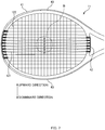
FIG. 1 is a plan view and a side view of a tennis racket (hereinafter, racket 1). The left one is the plan view and the right one is the side view.FIG. 2 is a diagram illustrating how astring 12 is strung to aframe 11. Theracket 1 includes ahead 10 which hits a ball, agrip 20 which a player grips to hold theracket 1, and ashaft 30 that integrally connects thehead 10 and thegrip 20. For the purpose of illustration, the side where thehead 10 is located is referred to as a tip-end side, and the side where thegrip 20 is located is referred to as a grip end side in the longitudinal direction of theracket 1. Further, the direction orthogonal to the longitudinal direction on the hitting surface of the racket 1 (that is, on a plane along the hitting surface) is referred to as a width direction, and the direction orthogonal to the hitting surface of theracket 1 is referred to as a thickness direction. - The
head 10 includes: theframe 11 having a substantially elliptical shape extending in the longitudinal direction; thestring 12 strung inside theframe 11; and, abumper grommet 41, ayoke grommet 42 and aside grommet 43 which are attached to an outerperipheral face 11a of theframe 11. - As shown in
Fig. 2 , at the center portion in the thickness direction of the outerperipheral face 11a of theframe 11, agroove section 111 is provided along the entire circumference of theframe 11. Thegroove section 111 is provided with a string hole 13 (corresponding to a through hole) which penetrates from an innerperipheral face 11b to the outerperipheral face 11a of theframe 11 and through which thestring 12 is inserted. A plurality of string holes 13 is provided along the entire circumference of theframe 11. - How to string the
string 12 will be described taking thebumper grommet 41 as an example. Note that, the detailed description of each grommet will be given later. - The
bumper grommet 41 includes a plurality oftube sections 411 and abase section 412 that connects the plurality oftube sections 411 to one another. Thetube section 411 includes a communicating hole, and thestring 12 can be inserted through this communicating hole (details will be described later). Thebumper grommet 41 is attached on the outerperipheral face 11a of theframe 11 in such a manner that the tip portion of the tube section 411 (that is, the end portion in the side that does not connects to the base section 412) is inserted into thestring hole 13 from the outerperipheral face 11a side of theframe 11 and thebase section 412 is fitted into thegroove section 111 of theframe 11. - When the
string 12 is strung to theframe 11, the following processes are repeated: thestring 12 passes from the inside to the outside of theframe 11 through thetube section 411 of thebumper grommet 41; thestring 12 is turned back along thebase section 412 of thebumper grommet 41; and thestring 12 passes through thenext tube section 411. As a result, inside theframe 11, a plurality oflongitudinal strings 121 which are portions of thestrings 12 extending in the longitudinal direction are strung at intervals in the width direction. Further, a plurality oftransverse strings 122 which are portions of thestrings 12 extending in the width direction so as to intersect thelongitudinal strings 121 are strung at intervals in the longitudinal direction, and the net-like hitting surface is formed. - As shown in the left drawing of
Fig. 1 , theshaft 30 includes abase end portion 31 connecting to thegrip 20, a firstbranched portion 32a extending from thebase end portion 31 to the left-side end portion in the width direction of the grip-end side portion of theframe 11, and a secondbranched portion 32b extending from the firstbase end portion 31 to the right-side end portion in the width direction of the grip-end side portion of theframe 11. That is, theshaft 30 branches into two sections toward the tip-end side in the longitudinal direction (the direction from thegrip 20 to the frame 11) as seen from the thickness direction (the direction orthogonal to the hitting surface of the racket 1). Thus, anopening 33 extending in the thickness direction is formed by the grip-end side portion of theframe 11, the firstbranched portion 32a and the secondbranched portion 32b. -
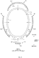
FIG. 3 is an explanatory diagram of each grommet to be attached to theframe 11. In theracket 1 of the present embodiment, thebumper grommet 41, theyoke grommet 42 and theside grommet 43 are attached on the outerperipheral face 11a of theframe 11 as shown inFig. 3 . Thestrings 12 are strung to theframe 11 through thebumper grommet 41, theyoke grommet 42 and theside grommet 43, and this results in protecting thestrings 12 and also damping vibrations when hitting the ball as well as providing the effects to be described later. - The
bumper grommet 41 is attached to the tip portion in the longitudinal direction of theframe 11. Further, theyoke grommet 42 is attached to the grip-end side portion in the longitudinal direction of theframe 11. Further, theside grommets 43 are attached on the right and left in the width direction of theframe 11. Two side grommets are to be attached to theframe 11 because theside grommets 43 are attached on the right and left. - The
bumper grommet 41 includes 24tube sections 411 through which thestring 12 is inserted and a strip-shapedbase section 412 which connects these 24tube sections 411. Note that, thebumper grommet 41 is provided with several types of tube sections (4111, 4112 and 4113 as reference numbers) as stated later. However, inFIG. 3 , the tube section is shown with thereference number 411 as a collectively-called reference number of the tube section in thebumper grommet 41. - Further, the
yoke grommet 42 includes sixtube sections 421 through which thestring 12 is inserted, and a strip-shapedbase section 422 which connects these sixtube sections 421. - Furthermore, the
side grommet 43 includes 20tube sections 431 through which the string is inserted, and a strip-shapedbase section 432 which connects these 20tube sections 431. Note that, theside grommet 43 is provided with several types of tube sections (4311, 4312 and 4313 as reference numbers) as stated later. However, inFIG. 3 , the tube section is shown with the reference number 413 as a collectively-called reference number of the tube section in thebumper grommet 43. - Next, each grommet will be described in detail.
-
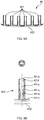
FIG. 4A is an explanatory diagram of thebumper grommet 41. Thebumper grommet 41 has 10first tube sections second tube sections 4112, fourthird tube sections 4113, and thebase section 412 which connects these tube sections. As stated later, thefirst tube section 4111 has an elongated hole shape in which an opening in the tip-end side of the communicating hole is formed wider in the arrangement direction of thetube sections 411 than an opening in thebase section 412 side. On the other hand, thesecond tube section 4112 and thethird tube section 4113 each have an opening in the tip-end side and an opening in the base section side, both of which are formed in a round hole shape. However, thesecond tube section 4112 and thethird tube section 4113 differ from each other in their diameters. Twostrings 12 are to be inserted through thethird tube section 4113, and thus the diameter of the third tube section is larger than that of the second tube section 41a2 through which one string is inserted. - The
bumper grommet 41 has a symmetrical shape, in which onesecond tube section 4112, onethird tube section 4113, foursecond tube sections 4112, onethird tube section 4113, and fivefirst tube sections 4111 are arranged from the left end to the center in order. -
Fig, 4B is an enlarged cross-sectional view of thefirst tube section 4111 in thebumper grommet 41.Fig. 4B indicates a communicatinghole 4111a in thefirst tube section 4111, a tip-end side opening 4111b of the communicatinghole 4111a, and a basesection side opening 4111c of the communicatinghole 4111a. - The base
section side opening 4111c of the communicatinghole 4111a has a round hole shape. On the other hand, the tipend side opening 4111b of the communicatinghole 4111a has an elongated hole shape having a longer diameter in the arrangement direction of thetube sections 411. Then, the longer diameter of the tipend side opening 4111b is wider than the diameter of the basesection side opening 4111c. It is desirable that the longer diameter of the tipend side opening 4111b is set to be about one and a half times as large as the diameter of the basesection side opening 4111c. However, setting to be about 1.2 to 2.0 times may also be applicable. Here, the diameter of the basesection side opening 4111c is about 1.6 mm, and the longer diameter of the tipend side opening 4111b is about 2.4 mm. - In this way, to have different diameters between the tip
end side opening 4111b and the basesection side opening 4111c in the direction in which thetube sections 411 are arranged, a firststraight part 4111d, aninclined part 4111e, and a secondstraight part 4111f are formed in the communicatinghole 4111a. The diameter of the secondstraight part 4111f is larger than that of the firststraight part 4111d in the arrangement direction of thetube sections 411, and theinclined part 4111e is provided to form such a shape. - Note that, the diameter (the shorter diameter) of the tip
end side opening 4111b and the diameter of the basesection side opening 4111c are formed in the same size in the thickness direction of theracket 1. Thus, theinclined part 4111e is not provided in the thickness direction of theracket 1. - Note that, the
bumper grommet 41 includes 10first tube sections 4111, and each longer diameter of the elongated holes of the tipend side openings 4111b of thefirst tube sections 4111 may be different from one another corresponding to the respective positions of thefirst tube sections 4111. -
Fig. 4C is an enlarged cross-sectional view of thesecond tube section 4112 in thebumper grommet 41.Fig. 4C illustrates a communicatinghole 4112a in thesecond tube section 4112, a tipend side opening 4112b of the communicatingholes 4112a and a basesection side opening 4112c of the communicatingholes 4112a. Thesecond tube section 4112 differs from the above-mentionedfirst tube section 4111. Both the tipend side opening 4112b and base section side opening 4112c have a round hole shape, and their respective diameters are also same with each other. That is, the communicatinghole 4112a is a straight round hole. - Further, the diameter of the communicating
holes 4112a in thesecond tube section 4112 is equal to the diameter of the basesection side opening 4111c in the first tube section 4111 (here, about 1.6 mm as stated above). In this way, the diameter of thesecond tube section 4112 is sized to allow onestring 12 to pass therethrough, so that thesecond tube section 4112 can appropriately support thelongitudinal string 121. - Further, although the enlarged cross-sectional view of the
third tube section 4113 is not shown, thethird tube section 4113 also has the tip end side opening and the base section side opening, both of which have a round hole shape and the same diameter. That is, the communicating hole of thethird tube section 4113 is also a straight round hole. However, the diameter of the communicating hole in thethird tube section 4113 is larger than that of the communicating hole in thesecond tube section 4112. This is because two strings are to be inserted through thethird tube section 4113. -
FIG. 5A is an explanatory diagram of theyoke grommet 42. Theyoke grommet 42 includes fourtube sections 421 and abase section 422 which connects these tube sections. Theyoke grommet 42 also has a symmetrical shape. Further, thetube section 421 of theyoke grommet 42 has substantially the same shape as thefirst tube section 4111 in the above-mentionedbumper grommet 41. -
Fig. 5B is an enlarged cross-sectional view of thetube section 421 of theyoke grommet 42.Fig. 5B illustrates a communicatingholes 421a in thetube section 421, a tip end side opening 421b of the communicatinghole 421a, and a basesection side opening 421c of the communicatinghole 421a. - The base
section side opening 421c of the communicatingholes 421a has a round hole shape. On the other hand, the tip end side opening 421b of the communicatingholes 421a has an elongated hole shape having a longer diameter in the arrangement direction of thetube sections 421. Then, the longer diameter of the tipend side opening 421b is greater than the diameter of the basesection side opening 421c. It is desirable that the longer diameter of the tipend side opening 421b is set to be about one and a half times as large as the diameter of the basesection side opening 421c. However, setting to be about 1.2 to 2.0 times may also be applicable. Here, the diameter of the basesection side opening 421c is about 1.8 mm, and the longer diameter of the tipend side opening 421b is about 2.8 mm. - To form such a shape, the
tube section 421 includes a firststraight part 421d, aninclined part 421e and a secondstraight part 421f as well. - Note that, the
yoke grommet 42 includes 16tube sections 421, and each longer diameter of the elongated holes of the tipend side openings 421b in thetube sections 421 may be different from one another corresponding to the respective positions of thetube section 421. -
Fig. 6A is an explanatory diagram of theside grommet 43. Theside grommet 43 includes eightfirst tube sections 4311, tensecond tube sections 4312, twothird tube sections 4313, and abase section 432 which connects these tube sections. As stated later, the tipend side opening 4311b of thefirst tube section 4311 has an elongated hole shape having a longer diameter in the thickness direction of theracket 1. Thus, thefirst tube section 4311 of theside grommet 43 has a different shape from thefirst tube section 4111 of thebumper grommet 41 and thetube section 421 of theyoke grommet 42 in terms of the direction of the longer diameter. - In the
side grommet 43, fourfirst tube sections 4311, foursecond tube sections 4312, fourfirst tube sections 4311, onethird tube section 4313, threesecond tube sections 4312, onethird tube section 4313, and threesecond tube sections 4312 are arranged from the tip-end side to the grip end side of theframe 10 in order. -
FIG. 6B is an enlarged cross-sectional view of thefirst tube section 4311 of theside grommet 43.Fig. 6B is a cross-sectional view taken along A-A inFig. 6A . It should be noted thatFIG. 6B differs from the cross-sectional views shown in the above-mentionedFIG. 4B andFig. 5B in the cross-sectional direction.FIG. 6B illustrates a communicatingholes 4311a in thefirst tube section 4311, a tipend side opening 4311b of the communicatinghole 4311a, and a basesection side opening 4311c of the communicatinghole 4311a. - The base
section side opening 4311c of the communicatinghole 4311a has a round hole shape. On the other hand, the tipend side opening 4311b of the communicatinghole 4311a has an elongated hole shape having a longer diameter in the thickness direction of theracket 1. Then, the tipend side opening 4311b is wider than the diameter of the basesection side opening 4311c. It is desirable that the longer diameter of the tipend side opening 4311b is set to be about one and a half times as large as the diameter of the basesection side opening 4311c. However, setting to be about 1.2 to 2.0 times may be applicable. Here, the diameter of the basesection side opening 4311c is about 1.6 mm, and the longer diameter of the tipend side opening 4311b is about 2.4 mm. - Thus, to have different diameters in the thickness direction of the
racket 1 between the tipend side opening 4311b and the basesection side opening 4311c, a firststraight part 4311d, aninclined part 4311e and a secondstraight part 4311f are formed in the communicatinghole 4311a. The diameter of the secondstraight part 4311f is larger than that of the firststraight part 4311d in the thickness direction of theracket 1, and theinclined part 4311e is provided to form such a shape. - Note that, the diameter (shorter diameter) of the tip
end side opening 4311b and the diameter of the basesection side opening 4311c are formed in the same size in the arrangement direction of thetube sections 431. Thus, theinclined part 4311e is not provided in the arrangement direction of thetube sections 431. - Note that, the
side grommet 43 includes eightfirst tube sections 4311, and each longer diameter of the elongated holes of the tipend side openings 4311b in thefirst tube sections 4311 may be different from one another corresponding to the respective positions of thefirst tube sections 4311. -
FIG. 6C is an enlarged cross-sectional view of thesecond tube section 4312 in theside grommet 43.FIG. 6C illustrates a communicatinghole 4312a of thesecond tube section 4312, a tipend side opening 4312b of the communicatinghole 4312a, and a basesection side opening 4312c of the communicatinghole 4312a. Thesecond tube section 4312 differs from the foregoingfirst tube section 4311, and both the tipend side opening 4312b and basesection side opening 4312c are round holes and also have the same diameter with each other. That is, the communicatinghole 4312a is a straight communicating hole. - Further, the diameter of the communicating
hole 4312a of thesecond tube section 4312 is equal to the diameter of the basesection side opening 4311c of the first tube section 4311 (here, about 1.6 mm as stated above). In this way, the diameter of thesecond tube section 4312 is sized to allow onestring 12 to be inserted therethrough, so that thesecond tube section 4312 can appropriately support thetransverse string 122. - Further, although the enlarged cross-sectional view of the
third tube section 4313 is not shown, thethird tube section 4313 also has the tip end side opening and the base section side opening, both of which have a round hole shape and the same diameter. That is, the communicating hole of thethird tube section 4313 is also a straight round hole. However, the diameter of the communicating hole of thethird tube section 4313 is larger than that of the communicating hole of thesecond tube section 4312. This is because two strings are to be inserted through thethird tube section 4313. -
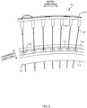
FIG. 7 is an explanatory diagram illustrating the movement of the strings when the ball is brought into contact with the strings.FIG. 7 illustrates theframe 11 of theracket 1 and thestrings 12 strung to theframe 11. Further, a ball B being brought into contact with theframe 11 is shown by a broken line, and then the displacement path of thelongitudinal strings 121 when hitting the ball B so as to rub the ball upward is shown by solid lines with arrows. Moreover, the cross-sectional form of only the parts including thefirst tube sections 4111 of thebumper grommet 41 and thefirst tube sections 4311 of theyoke grommet 42 are shown to indicate the inside thereof. Further, an upward direction and a downward direction are shown inFIG. 7 . The upward direction and the downward direction inFIG. 7 are defined as the upward and downward directions when swinging the racket, and thus it should be noted that those directions are different from the directions shown inFIG. 1 illustrating theracket 1. - When swinging the
racket 1 and hitting the ball B back, a player generally swings theracket 1 so as to allow theracket 1 to rub the ball B upward (to allow the racket to move from downward to upward). Thus, a difference in atmospheric pressure between the upside and downside of the ball B occurs by rotating the ball B in the forward direction. When the ball B is rotating in the forward direction, the atmospheric pressure in the downside of the ball B becomes lower than the upside thereof. This makes the ball B easier to fall, rather than the case where the ball B is not rotated. - In
FIG. 7 , thelongitudinal strings 121 shown by broken lines are illustrated along with thelongitudinal strings 121 shown by solid lines. In theracket 1 of the present embodiment, thestrings 12 shown by the broken lines indicate thelongitudinal strings 121 which have been displaced when the strings have been brought into contact with the ball B. Also in the case of theracket 1 according to the present embodiment, when swinging theracket 1 as stated above, thelongitudinal strings 121 which have been brought into contact with the ball B are displaced downward for a moment by hitting the ball B back so as to rub the ball upward. Then, thelongitudinal strings 121 try to return to the original positions after being displaced downward. - According to the
racket 1 to which thebumper grommet 41 of the present embodiment is attached, the tipend side opening 4111b of thefirst tube section 411 of thebumper grommet 41 is wider than the basesection side opening 4111c in the direction in which a plurality of tube sections is arranged. Thus, when hitting a ball so as to rub the ball upward, the displacement of thelongitudinal strings 121 of theracket 1 in the width direction becomes larger compared with that of a common racket. Further, when being displaced in the width direction, thelongitudinal strings 121 move with a basesection side opening 4111c side as a support point. Thus, thelongitudinal strings 121 return to the original positions immediately after moving in the width direction, and this results in a larger amount of rotations of the ball. Specifically, theracket 1 having the foregoing configuration makes it possible to enlarge a movable range of thelongitudinal strings 121, so that the number of rotations of the hit ball can be increased. Note that, the same applies to theracket 1 to which theyoke grommet 42 is attached. - Moreover, according to the
racket 1 to which thebumper grommet 41 of the present embodiment is attached, the diameter of the tipend side opening 4111b and the diameter of the basesection side opening 4111c are equal in the thickness direction of theracket 1, and thereby allowing thelongitudinal strings 121 to move along the direction in which the plurality oftube sections 411 is arranged. Note that, the same applies to theracket 1 to which theyoke grommet 42 is attached. - Furthermore, according to the
racket 1 to which thebumper grommet 41 of the present embodiment is attached, the diameter of the basesection side opening 4111c is sized to allow onelongitudinal string 12 to pass therethrough. Thus, thelongitudinal strings 121 can be moved in the width direction of theracket 1 with the firststraight part 4111d in the side of the basesection side opening 4111c as a support point. For this reason, thelongitudinal strings 121 can return to the original positions after being moved. Note that, the same applies to theracket 1 to which theyoke grommet 42 is attached. - If the
first tube section 4111 of thebumper grommet 41, thetube section 421 of theyoke grommet 42, and thefirst tube section 4311 of theside grommet 43 are merely straight elongated holes, once thestrings 121 move, thestrings 12 slidably move in the elongated hole and become in a state of hardly returning to the original positions (in a state where the strings have approached one side). On the other hand, when the grommet of the present embodiment is used, the strings immediately return to the original positions even in a case where the strings have been brought into contact with the ball and then moved once. - Further, according to the
racket 1 to which theside grommet 42 of the present embodiment is attached, when being in contact with the ball B, thetransverse strings 122 can be largely moved in the thickness direction of the racket and then can be moved to the original positions. Although this allows a repulsive force of the ball B to be increased against theracket 1, a larger amount of rotation of the ball B in the forward direction can be achieved with such an above-mentioned configuration, and thereby allowing the ball to appropriately fall into the opponent's court. - Note that, when the
side grommet 43 is fitted into theframe 11, thefirst tube sections 4311 are positioned slightly in the tip end side and the grip end side from the center. In this way, a higher repulsive force against the ball can be obtained without impairing hit feeling. - Next, effectiveness of providing a larger amount of rotation will be studied. With a swing machine, the difference in the amount of rotation is measured between the
racket 1 of the present embodiment and the racket having communicating holes which are merely round holes in all tube sections of the grommet. In the results of the measurements, in a case where the amount of rotation of the ball against the racket that adopts the grommet having the communicating holes which are all merely round holes is 100, the amount of rotation when the ball is hit back by theracket 1 of the present embodiment is 110. That is, the amount of rotation can be increased by 10%. - Further, in a case where the amount of rotation of the ball is measured using the racket in which the
bumper grommet 41 and theyoke grommet 42 of the present embodiment are adopted and only the side grommet has communicating holes of the tube sections which are all merely round holes, the amount of rotation is 105. That is, even in the case of using the racket which employs only thebumper grommet 41 and theyoke grommet 42 disclosed in the present embodiment, the amount of rotation can be increased by 5%. - The above-described embodiment is for facilitating understanding of the present invention, and is not intended to limit the interpretation of the present invention. As a matter of course, the present invention can be changed and modified without departing from the spirit of the invention, and equivalents thereof are encompassed in the present invention.
- For example, both the
bumper grommet 41 and theyoke grommet 42 are used in the above-mentioned embodiment. However, even in the case of using either one of them, the number of rotations of the hit ball can be increased due to the similar reason to the above. - Further, the
tube sections 4311 of theside grommet 43 include the communicating holes widening in the thickness direction of the racket. However, the number of rotations of the hit ball can be increased by the effects of thebumper grommet 41 and theyoke grommet 42 without having such communicating holes in theside grommet 43. - Further, the above-mentioned embodiment is in a form that the grommet 40 is attached to the
frame 11. However, the strings may be directly strung to theframe 11 without using the grommet 40. - In this case, the through hole in the frame of the racket includes an outer peripheral face side opening in the outer peripheral face side of the frame and an inner peripheral face side opening in the inner peripheral face side of the frame. Then, the inner peripheral side openings of at least some number of through holes, of the through holes through which the longitudinal strings of the racket are inserted, are wider than the outer peripheral side openings in the direction in which a plurality of through holes is arranged.
- Even in such a racket, since the inner peripheral side openings are wider than the outer peripheral side openings in the direction in which the plurality of tube sections is arranged, the longitudinal strings can be easily moved more largely toward the intersecting direction when hitting a ball so as to rub the ball upward. Further, the longitudinal strings move with the outer peripheral side opening side as a support point, and thus the strings return to the original positions while being in contact with the ball immediately after moving to the intersecting direction. This increases the displacement of the longitudinal strings while being brought into contact with the ball in comparison with a common racket. The number of rotations of the hit ball can be increased with the foregoing racket because the number of rotations of the hit ball is increased corresponding to the displacement of the strings while being brought into contact with the ball.
- Further, in the above-mentioned embodiment, a tennis racket is taken as an example of a racket associated with the present embodiment. However, the invention is not limited thereto. For example, the present embodiment may be applied to a squash racket, a badminton racket and the like. Also, in the above-mentioned embodiment, the
racket 1 in which thestrings 12 are strung inside theframe 11 is taken as an example of a racket. However, the invention is not limited thereto, and a racket in which thestrings 12 have not been strung may also be employed. - Further, in the foregoing embodiment, the explanation was given on a case where the number of rotations in the forward direction of the ball was increased. However, the same effect will be achieved even in a case where the number of rotations in the backward direction of the ball is increased.
-
- 1
- racket
- 10
- head
- 11
- frame
- 11a
- outer peripheral face
- 11b
- inner peripheral face
- 12
- string
- 13
- string hole (through hole)
- 20
- grip
- 30
- shaft
- 31
- base end portion
- 32a
- first branched portion
- 32
- second branched portion
- 33
- opening
- 41
- bumper grommet
- 42
- yoke grommet
- 43
- side grommet
- 44
- groove section
- 121
- longitudinal string
- 122
- transverse string
the tip end side openings of at least some number of the tube sections, of the plurality of tube sections through which a string to be strung in a direction along a longitudinal direction of the racket is inserted, being wider than the base section side openings in a direction in which the plurality of tube sections is arranged.
Claims (5)
- A racket (1) extending in a longitudinal direction and a thickness direction which is orthogonal to the longitudinal direction, said racket comprising:a grip (20);an annular frame (11) provided with a plurality of through holes (13) each extending from an inner peripheral face (11b) of the frame to an outer peripheral face (11a) of the frame in a respective transverse direction which is orthogonal to said thickness direction;a shaft (30) connecting the grip (20) and the frame (11); andat least one grommet (41, 42) attached to the outer peripheral face (11a) of the frame (11),
said at least one grommet (41, 42) including:a plurality of tube sections (411, 421) each of which is inserted into a respective one of said plurality of through holes (13) provided in the frame, and is adapted to receive a longitudinal string (121) to be strung in the longitudinal of the racket (1); anda base section (412, 422) that connects the plurality of tube sections (411, 421) to one another,the tube sections (411, 421) each including a communicating hole (4111a, 4112a, 421a) that communicates a base section side opening (4111c, 4112c, 421c) on a base section side of the communicating hole with a tip end side opening (4111b, 4112b, 421b) of the communicating hole, said base section side openings each having a round hole shape; characterized in thateach tip end side opening (4111b, 421b) of at least some tube sections (4111, 421) of said plurality of tube sections (411, 421) has an elongated hole shape having a longer diameter in a direction which is orthogonal to each of said thickness direction and said transverse direction, said longer diameter being longer than a diameter of a respective one of said base section side openings (4111c, 421c) of said at least some tube sections (4111, 421). - A racket (1) according to claim 1, wherein
said at least one grommet (41, 42) is attached to at least either one of a tip end side or a grip end side of the frame (11) in the longitudinal direction of the racket (1). - A racket (1) according to claim 1 or 2, wherein
the size of the base section side opening (4111c, 4112c, 421c) and the size of the tip end side opening (4111b, 4112b, 421b) of each tube section of said plurality of tube sections (411, 421) are equal with each other in the thickness direction of the racket (1). - A racket (1) according to any one of claims 1 to 3, wherein
the racket (1) further includes a pair of side grommets (43) each having a plurality of tube sections (4311, 4312, 4313) each of which is adapted to receive a transverse string (122) to be strung in a width direction of the racket (1), said width direction being orthogonal to said longitudinal direction of the racket (1), and wherein at least some tube sections (4311) of said plurality of tube sections (4311, 4312, 4313) of each side grommet (43) each have a respective tip end side opening (4311b) in the shape of an elongated hole which has a longer diameter in the thickness direction of the racket (1). - A grommet (41, 42) to be attached to a racket (1) which extends in a longitudinal direction and a thickness direction which is orthogonal to the longitudinal direction, said racket (1) including a grip (20), an annular frame (11) provided with a plurality of through holes (13) each extending from an inner peripheral face (11b) of the frame to an outer peripheral face (11a) of the frame in a respective transverse direction which is orthogonal to said thickness direction, and a shaft (30) connecting the grip (20) and the frame (11),
the grommet (41, 42) comprising:a plurality of tube sections (411, 421) each of which is adapted to be inserted into a respective one of said plurality of through holes (13) provided in the frame (11) and adapted to receive a longitudinal string (121) to be strung in the longitudinal direction of the racket (1); anda base section (412, 422) that connects the plurality of tube sections (411, 421) to one another,the tube sections (411, 421) each including a communicating hole (4111a, 4112a, 421a) that communicates a base section side opening (4111c, 4112c, 421c) on a base section side of the communicating hole with a tip end side opening (4111b, 4112b, 421b) of the communicating hole, said base section side openings each having a round hole shape; characterized in that
each tip end side opening (4111b, 421b) of at least some tube sections (4111, 421) of the plurality of tube sections (411, 421) has an elongated hole shape having a longer diameter in a direction which is orthogonal to each of said thickness direction and said transverse direction, said longer diameter being longer than a diameter of a respective one of said base section side openings (4111c, 421c) of said at least some tube sections (4111, 421).
Applications Claiming Priority (2)
| Application Number | Priority Date | Filing Date | Title |
|---|---|---|---|
| JP2014103998A JP5992471B2 (en) | 2014-05-20 | 2014-05-20 | Racket and grommet |
| PCT/JP2014/066142 WO2015177937A1 (en) | 2014-05-20 | 2014-06-18 | Racket and grommet |
Publications (3)
| Publication Number | Publication Date |
|---|---|
| EP3132832A1 EP3132832A1 (en) | 2017-02-22 |
| EP3132832A4 EP3132832A4 (en) | 2017-08-23 |
| EP3132832B1 true EP3132832B1 (en) | 2018-12-19 |
Family
ID=54553628
Family Applications (1)
| Application Number | Title | Priority Date | Filing Date |
|---|---|---|---|
| EP14887707.9A Active EP3132832B1 (en) | 2014-05-20 | 2014-06-18 | Racket and grommet |
Country Status (5)
| Country | Link |
|---|---|
| US (1) | US9750989B2 (en) |
| EP (1) | EP3132832B1 (en) |
| JP (1) | JP5992471B2 (en) |
| CN (1) | CN105283229B (en) |
| WO (1) | WO2015177937A1 (en) |
Families Citing this family (14)
| Publication number | Priority date | Publication date | Assignee | Title |
|---|---|---|---|---|
| FR3034322B1 (en) * | 2015-04-01 | 2018-09-21 | Babolat Vs | TENNIS RACKET |
| CN106730689B (en) * | 2017-04-05 | 2022-05-06 | 东华理工大学 | tennis racket |
| CN108721850A (en) * | 2017-04-17 | 2018-11-02 | 陈正盛 | Line protection device for racket |
| DE102018003690B3 (en) | 2018-04-19 | 2019-05-09 | Head Technology Gmbh | Eyelet and eyelet tape for ball game rackets |
| JP7286350B2 (en) * | 2019-03-08 | 2023-06-05 | ヨネックス株式会社 | racket |
| JP7286351B2 (en) * | 2019-03-08 | 2023-06-05 | ヨネックス株式会社 | racket |
| US11161016B2 (en) | 2019-03-19 | 2021-11-02 | Sumitomo Rubber Industries, Ltd. | Racket |
| JP7180474B2 (en) * | 2019-03-19 | 2022-11-30 | 住友ゴム工業株式会社 | racket |
| JP7180475B2 (en) * | 2019-03-19 | 2022-11-30 | 住友ゴム工業株式会社 | racket |
| JP7170687B2 (en) * | 2020-05-28 | 2022-11-14 | 美津濃株式会社 | racket frame and racket |
| FR3120542B1 (en) | 2021-03-09 | 2023-03-24 | Babolat Vs | Set of guide eyelets and sports racket fitted with such a set |
| USD1023203S1 (en) * | 2021-11-08 | 2024-04-16 | Sumitomo Rubber Industries, Ltd. | Tennis racket frame |
| JP7775644B2 (en) * | 2021-11-08 | 2025-11-26 | 住友ゴム工業株式会社 | racket |
| JPWO2024150797A1 (en) * | 2023-01-12 | 2024-07-18 |
Family Cites Families (21)
| Publication number | Priority date | Publication date | Assignee | Title |
|---|---|---|---|---|
| US4681319A (en) * | 1978-10-05 | 1987-07-21 | Gene Zilinskas | Racket having unique string mount |
| JPS6028463Y2 (en) * | 1979-03-09 | 1985-08-28 | ヤマハ株式会社 | Yoke parts for rackets |
| JPS6320867U (en) * | 1986-07-25 | 1988-02-10 | ||
| ATE132381T1 (en) * | 1992-01-29 | 1996-01-15 | Voelkl Franz Ski | BALL GAME RACKETS, ESPECIALLY TENNIS RACKETS |
| CN2156898Y (en) * | 1993-03-30 | 1994-02-23 | 刘继志 | racket cover |
| CN2167741Y (en) * | 1993-09-29 | 1994-06-08 | 刘继志 | racket cover |
| US5944624A (en) * | 1996-12-23 | 1999-08-31 | Prince Sports Group, Inc. | Notched, slotted grommet for sports racquet |
| US5833560A (en) * | 1997-03-19 | 1998-11-10 | Prince Sports Group, Inc. | Racquetball racquet |
| US6050909A (en) * | 1997-06-13 | 2000-04-18 | Wilson Sporting Goods Co. | Game racquet with string slots in inner wall |
| JP3981276B2 (en) * | 2002-01-31 | 2007-09-26 | 美津濃株式会社 | Gut protector and racket frame equipped with the got protector |
| ATE426436T1 (en) * | 2006-04-11 | 2009-04-15 | Prince Sports Inc | METHOD FOR PRODUCING A SPORTS RACKET |
| JP4911772B2 (en) * | 2007-07-10 | 2012-04-04 | Sriスポーツ株式会社 | racket |
| US20110165975A1 (en) * | 2007-11-26 | 2011-07-07 | Brett Bothwell | System and Method for a Pre-Formed Reinforcement Member for an Opening in a Game Racket |
| US20090165243A1 (en) * | 2008-01-02 | 2009-07-02 | Kamran Yazdi | Grommet tie off (gto) |
| JP5401185B2 (en) * | 2009-06-30 | 2014-01-29 | ヨネックス株式会社 | racket |
| US7887444B1 (en) * | 2009-08-13 | 2011-02-15 | Wilson Sporting Goods Co. | Racquet having articulating grommet assemblies |
| US8834306B2 (en) * | 2011-07-20 | 2014-09-16 | Ef Composite Technologies, L.P. | Racquet with elongated grommet barrels |
| JP6196786B2 (en) * | 2013-03-06 | 2017-09-13 | ヨネックス株式会社 | racket |
| JP6147053B2 (en) * | 2013-03-28 | 2017-06-14 | ダンロップスポーツ株式会社 | Racket frame |
| US20140335979A1 (en) * | 2013-05-09 | 2014-11-13 | Ef Composite Technologies, L.P. | Racquet having elongated grommet barrels with improved damping characteristics |
| DE102013018837B3 (en) * | 2013-11-08 | 2015-02-26 | Head Technology Gmbh | Ösenband |
-
2014
- 2014-05-20 JP JP2014103998A patent/JP5992471B2/en active Active
- 2014-06-18 US US14/899,750 patent/US9750989B2/en active Active
- 2014-06-18 WO PCT/JP2014/066142 patent/WO2015177937A1/en not_active Ceased
- 2014-06-18 EP EP14887707.9A patent/EP3132832B1/en active Active
- 2014-06-18 CN CN201480023234.6A patent/CN105283229B/en active Active
Non-Patent Citations (1)
| Title |
|---|
| None * |
Also Published As
| Publication number | Publication date |
|---|---|
| WO2015177937A1 (en) | 2015-11-26 |
| US9750989B2 (en) | 2017-09-05 |
| CN105283229A (en) | 2016-01-27 |
| JP2015217192A (en) | 2015-12-07 |
| CN105283229B (en) | 2017-05-03 |
| JP5992471B2 (en) | 2016-09-14 |
| EP3132832A1 (en) | 2017-02-22 |
| EP3132832A4 (en) | 2017-08-23 |
| US20170173407A1 (en) | 2017-06-22 |
Similar Documents
| Publication | Publication Date | Title |
|---|---|---|
| US9750989B2 (en) | Racket and grommet | |
| JP6782154B2 (en) | Grommets and rackets | |
| US10561907B2 (en) | Racket frame | |
| US10406406B2 (en) | Grommet and racket | |
| JP7775644B2 (en) | racket | |
| CN113543855B (en) | Grommet and racket | |
| JPWO2016195037A1 (en) | racket | |
| CN113543856B (en) | Grommet and racket | |
| WO2016195035A1 (en) | Badminton racket | |
| JP6196786B2 (en) | racket | |
| KR101681764B1 (en) | Golf club head and golf club | |
| JP6397857B2 (en) | Racket and grommet | |
| JP6163324B2 (en) | Racket and grommet | |
| JP2016221148A (en) | racket | |
| CN104174144B (en) | Racket | |
| JP6427405B2 (en) | Badminton racket | |
| JP2021186187A (en) | Racket frame and racket | |
| KR20160002936U (en) | Racket frame | |
| JP6427406B2 (en) | Badminton racket | |
| JP3185201U (en) | Under tape for sports equipment and tools with grips | |
| WO2024150797A1 (en) | Racket frame and racket | |
| JP2009034229A (en) | racket | |
| JP2017000238A (en) | Badminton racket |
Legal Events
| Date | Code | Title | Description |
|---|---|---|---|
| PUAI | Public reference made under article 153(3) epc to a published international application that has entered the european phase |
Free format text: ORIGINAL CODE: 0009012 |
|
| STAA | Information on the status of an ep patent application or granted ep patent |
Free format text: STATUS: REQUEST FOR EXAMINATION WAS MADE |
|
| 17P | Request for examination filed |
Effective date: 20151002 |
|
| AK | Designated contracting states |
Kind code of ref document: A1 Designated state(s): AL AT BE BG CH CY CZ DE DK EE ES FI FR GB GR HR HU IE IS IT LI LT LU LV MC MK MT NL NO PL PT RO RS SE SI SK SM TR |
|
| AX | Request for extension of the european patent |
Extension state: BA ME |
|
| A4 | Supplementary search report drawn up and despatched |
Effective date: 20170725 |
|
| DAX | Request for extension of the european patent (deleted) | ||
| RIC1 | Information provided on ipc code assigned before grant |
Ipc: A63B 49/00 20150101ALI20170719BHEP Ipc: A63B 49/022 20150101AFI20170719BHEP |
|
| REG | Reference to a national code |
Ref country code: DE Ref legal event code: R079 Ref document number: 602014038428 Country of ref document: DE Free format text: PREVIOUS MAIN CLASS: A63B0051100000 Ipc: A63B0049022000 |
|
| GRAP | Despatch of communication of intention to grant a patent |
Free format text: ORIGINAL CODE: EPIDOSNIGR1 |
|
| STAA | Information on the status of an ep patent application or granted ep patent |
Free format text: STATUS: GRANT OF PATENT IS INTENDED |
|
| RIC1 | Information provided on ipc code assigned before grant |
Ipc: A63B 49/00 20150101ALI20180525BHEP Ipc: A63B 49/022 20150101AFI20180525BHEP |
|
| INTG | Intention to grant announced |
Effective date: 20180628 |
|
| GRAS | Grant fee paid |
Free format text: ORIGINAL CODE: EPIDOSNIGR3 |
|
| GRAA | (expected) grant |
Free format text: ORIGINAL CODE: 0009210 |
|
| STAA | Information on the status of an ep patent application or granted ep patent |
Free format text: STATUS: THE PATENT HAS BEEN GRANTED |
|
| AK | Designated contracting states |
Kind code of ref document: B1 Designated state(s): AL AT BE BG CH CY CZ DE DK EE ES FI FR GB GR HR HU IE IS IT LI LT LU LV MC MK MT NL NO PL PT RO RS SE SI SK SM TR |
|
| REG | Reference to a national code |
Ref country code: GB Ref legal event code: FG4D |
|
| REG | Reference to a national code |
Ref country code: CH Ref legal event code: EP |
|
| REG | Reference to a national code |
Ref country code: IE Ref legal event code: FG4D |
|
| REG | Reference to a national code |
Ref country code: DE Ref legal event code: R096 Ref document number: 602014038428 Country of ref document: DE |
|
| REG | Reference to a national code |
Ref country code: AT Ref legal event code: REF Ref document number: 1078055 Country of ref document: AT Kind code of ref document: T Effective date: 20190115 |
|
| REG | Reference to a national code |
Ref country code: NL Ref legal event code: MP Effective date: 20181219 |
|
| PG25 | Lapsed in a contracting state [announced via postgrant information from national office to epo] |
Ref country code: LV Free format text: LAPSE BECAUSE OF FAILURE TO SUBMIT A TRANSLATION OF THE DESCRIPTION OR TO PAY THE FEE WITHIN THE PRESCRIBED TIME-LIMIT Effective date: 20181219 Ref country code: HR Free format text: LAPSE BECAUSE OF FAILURE TO SUBMIT A TRANSLATION OF THE DESCRIPTION OR TO PAY THE FEE WITHIN THE PRESCRIBED TIME-LIMIT Effective date: 20181219 Ref country code: LT Free format text: LAPSE BECAUSE OF FAILURE TO SUBMIT A TRANSLATION OF THE DESCRIPTION OR TO PAY THE FEE WITHIN THE PRESCRIBED TIME-LIMIT Effective date: 20181219 Ref country code: BG Free format text: LAPSE BECAUSE OF FAILURE TO SUBMIT A TRANSLATION OF THE DESCRIPTION OR TO PAY THE FEE WITHIN THE PRESCRIBED TIME-LIMIT Effective date: 20190319 Ref country code: FI Free format text: LAPSE BECAUSE OF FAILURE TO SUBMIT A TRANSLATION OF THE DESCRIPTION OR TO PAY THE FEE WITHIN THE PRESCRIBED TIME-LIMIT Effective date: 20181219 Ref country code: NO Free format text: LAPSE BECAUSE OF FAILURE TO SUBMIT A TRANSLATION OF THE DESCRIPTION OR TO PAY THE FEE WITHIN THE PRESCRIBED TIME-LIMIT Effective date: 20190319 |
|
| REG | Reference to a national code |
Ref country code: LT Ref legal event code: MG4D |
|
| REG | Reference to a national code |
Ref country code: AT Ref legal event code: MK05 Ref document number: 1078055 Country of ref document: AT Kind code of ref document: T Effective date: 20181219 |
|
| PG25 | Lapsed in a contracting state [announced via postgrant information from national office to epo] |
Ref country code: SE Free format text: LAPSE BECAUSE OF FAILURE TO SUBMIT A TRANSLATION OF THE DESCRIPTION OR TO PAY THE FEE WITHIN THE PRESCRIBED TIME-LIMIT Effective date: 20181219 Ref country code: AL Free format text: LAPSE BECAUSE OF FAILURE TO SUBMIT A TRANSLATION OF THE DESCRIPTION OR TO PAY THE FEE WITHIN THE PRESCRIBED TIME-LIMIT Effective date: 20181219 Ref country code: RS Free format text: LAPSE BECAUSE OF FAILURE TO SUBMIT A TRANSLATION OF THE DESCRIPTION OR TO PAY THE FEE WITHIN THE PRESCRIBED TIME-LIMIT Effective date: 20181219 Ref country code: GR Free format text: LAPSE BECAUSE OF FAILURE TO SUBMIT A TRANSLATION OF THE DESCRIPTION OR TO PAY THE FEE WITHIN THE PRESCRIBED TIME-LIMIT Effective date: 20190320 |
|
| PG25 | Lapsed in a contracting state [announced via postgrant information from national office to epo] |
Ref country code: NL Free format text: LAPSE BECAUSE OF FAILURE TO SUBMIT A TRANSLATION OF THE DESCRIPTION OR TO PAY THE FEE WITHIN THE PRESCRIBED TIME-LIMIT Effective date: 20181219 |
|
| PG25 | Lapsed in a contracting state [announced via postgrant information from national office to epo] |
Ref country code: ES Free format text: LAPSE BECAUSE OF FAILURE TO SUBMIT A TRANSLATION OF THE DESCRIPTION OR TO PAY THE FEE WITHIN THE PRESCRIBED TIME-LIMIT Effective date: 20181219 Ref country code: PT Free format text: LAPSE BECAUSE OF FAILURE TO SUBMIT A TRANSLATION OF THE DESCRIPTION OR TO PAY THE FEE WITHIN THE PRESCRIBED TIME-LIMIT Effective date: 20190419 Ref country code: PL Free format text: LAPSE BECAUSE OF FAILURE TO SUBMIT A TRANSLATION OF THE DESCRIPTION OR TO PAY THE FEE WITHIN THE PRESCRIBED TIME-LIMIT Effective date: 20181219 Ref country code: CZ Free format text: LAPSE BECAUSE OF FAILURE TO SUBMIT A TRANSLATION OF THE DESCRIPTION OR TO PAY THE FEE WITHIN THE PRESCRIBED TIME-LIMIT Effective date: 20181219 |
|
| PG25 | Lapsed in a contracting state [announced via postgrant information from national office to epo] |
Ref country code: SK Free format text: LAPSE BECAUSE OF FAILURE TO SUBMIT A TRANSLATION OF THE DESCRIPTION OR TO PAY THE FEE WITHIN THE PRESCRIBED TIME-LIMIT Effective date: 20181219 Ref country code: RO Free format text: LAPSE BECAUSE OF FAILURE TO SUBMIT A TRANSLATION OF THE DESCRIPTION OR TO PAY THE FEE WITHIN THE PRESCRIBED TIME-LIMIT Effective date: 20181219 Ref country code: IS Free format text: LAPSE BECAUSE OF FAILURE TO SUBMIT A TRANSLATION OF THE DESCRIPTION OR TO PAY THE FEE WITHIN THE PRESCRIBED TIME-LIMIT Effective date: 20190419 Ref country code: EE Free format text: LAPSE BECAUSE OF FAILURE TO SUBMIT A TRANSLATION OF THE DESCRIPTION OR TO PAY THE FEE WITHIN THE PRESCRIBED TIME-LIMIT Effective date: 20181219 Ref country code: SM Free format text: LAPSE BECAUSE OF FAILURE TO SUBMIT A TRANSLATION OF THE DESCRIPTION OR TO PAY THE FEE WITHIN THE PRESCRIBED TIME-LIMIT Effective date: 20181219 |
|
| REG | Reference to a national code |
Ref country code: DE Ref legal event code: R097 Ref document number: 602014038428 Country of ref document: DE |
|
| PLBE | No opposition filed within time limit |
Free format text: ORIGINAL CODE: 0009261 |
|
| STAA | Information on the status of an ep patent application or granted ep patent |
Free format text: STATUS: NO OPPOSITION FILED WITHIN TIME LIMIT |
|
| PG25 | Lapsed in a contracting state [announced via postgrant information from national office to epo] |
Ref country code: AT Free format text: LAPSE BECAUSE OF FAILURE TO SUBMIT A TRANSLATION OF THE DESCRIPTION OR TO PAY THE FEE WITHIN THE PRESCRIBED TIME-LIMIT Effective date: 20181219 Ref country code: DK Free format text: LAPSE BECAUSE OF FAILURE TO SUBMIT A TRANSLATION OF THE DESCRIPTION OR TO PAY THE FEE WITHIN THE PRESCRIBED TIME-LIMIT Effective date: 20181219 |
|
| 26N | No opposition filed |
Effective date: 20190920 |
|
| PG25 | Lapsed in a contracting state [announced via postgrant information from national office to epo] |
Ref country code: MC Free format text: LAPSE BECAUSE OF FAILURE TO SUBMIT A TRANSLATION OF THE DESCRIPTION OR TO PAY THE FEE WITHIN THE PRESCRIBED TIME-LIMIT Effective date: 20181219 |
|
| REG | Reference to a national code |
Ref country code: CH Ref legal event code: PL |
|
| PG25 | Lapsed in a contracting state [announced via postgrant information from national office to epo] |
Ref country code: SI Free format text: LAPSE BECAUSE OF FAILURE TO SUBMIT A TRANSLATION OF THE DESCRIPTION OR TO PAY THE FEE WITHIN THE PRESCRIBED TIME-LIMIT Effective date: 20181219 |
|
| REG | Reference to a national code |
Ref country code: BE Ref legal event code: MM Effective date: 20190630 |
|
| PG25 | Lapsed in a contracting state [announced via postgrant information from national office to epo] |
Ref country code: TR Free format text: LAPSE BECAUSE OF FAILURE TO SUBMIT A TRANSLATION OF THE DESCRIPTION OR TO PAY THE FEE WITHIN THE PRESCRIBED TIME-LIMIT Effective date: 20181219 |
|
| PG25 | Lapsed in a contracting state [announced via postgrant information from national office to epo] |
Ref country code: IE Free format text: LAPSE BECAUSE OF NON-PAYMENT OF DUE FEES Effective date: 20190618 |
|
| PG25 | Lapsed in a contracting state [announced via postgrant information from national office to epo] |
Ref country code: LU Free format text: LAPSE BECAUSE OF NON-PAYMENT OF DUE FEES Effective date: 20190618 Ref country code: BE Free format text: LAPSE BECAUSE OF NON-PAYMENT OF DUE FEES Effective date: 20190630 Ref country code: LI Free format text: LAPSE BECAUSE OF NON-PAYMENT OF DUE FEES Effective date: 20190630 Ref country code: CH Free format text: LAPSE BECAUSE OF NON-PAYMENT OF DUE FEES Effective date: 20190630 |
|
| PG25 | Lapsed in a contracting state [announced via postgrant information from national office to epo] |
Ref country code: CY Free format text: LAPSE BECAUSE OF FAILURE TO SUBMIT A TRANSLATION OF THE DESCRIPTION OR TO PAY THE FEE WITHIN THE PRESCRIBED TIME-LIMIT Effective date: 20181219 |
|
| PG25 | Lapsed in a contracting state [announced via postgrant information from national office to epo] |
Ref country code: HU Free format text: LAPSE BECAUSE OF FAILURE TO SUBMIT A TRANSLATION OF THE DESCRIPTION OR TO PAY THE FEE WITHIN THE PRESCRIBED TIME-LIMIT; INVALID AB INITIO Effective date: 20140618 Ref country code: MT Free format text: LAPSE BECAUSE OF FAILURE TO SUBMIT A TRANSLATION OF THE DESCRIPTION OR TO PAY THE FEE WITHIN THE PRESCRIBED TIME-LIMIT Effective date: 20181219 |
|
| PG25 | Lapsed in a contracting state [announced via postgrant information from national office to epo] |
Ref country code: MK Free format text: LAPSE BECAUSE OF FAILURE TO SUBMIT A TRANSLATION OF THE DESCRIPTION OR TO PAY THE FEE WITHIN THE PRESCRIBED TIME-LIMIT Effective date: 20181219 |
|
| PGFP | Annual fee paid to national office [announced via postgrant information from national office to epo] |
Ref country code: IT Payment date: 20230623 Year of fee payment: 10 Ref country code: GB Payment date: 20230622 Year of fee payment: 10 |
|
| GBPC | Gb: european patent ceased through non-payment of renewal fee |
Effective date: 20240618 |
|
| PG25 | Lapsed in a contracting state [announced via postgrant information from national office to epo] |
Ref country code: GB Free format text: LAPSE BECAUSE OF NON-PAYMENT OF DUE FEES Effective date: 20240618 Ref country code: IT Free format text: LAPSE BECAUSE OF NON-PAYMENT OF DUE FEES Effective date: 20240618 |
|
| PGFP | Annual fee paid to national office [announced via postgrant information from national office to epo] |
Ref country code: DE Payment date: 20250618 Year of fee payment: 12 |
|
| PGFP | Annual fee paid to national office [announced via postgrant information from national office to epo] |
Ref country code: FR Payment date: 20250625 Year of fee payment: 12 |