EP3132518B1 - Système et procédé de protection de fréquence lors de la charge sans contact - Google Patents
Système et procédé de protection de fréquence lors de la charge sans contact Download PDFInfo
- Publication number
- EP3132518B1 EP3132518B1 EP15712027.0A EP15712027A EP3132518B1 EP 3132518 B1 EP3132518 B1 EP 3132518B1 EP 15712027 A EP15712027 A EP 15712027A EP 3132518 B1 EP3132518 B1 EP 3132518B1
- Authority
- EP
- European Patent Office
- Prior art keywords
- charging
- entity
- current
- frequency
- error value
- Prior art date
- Legal status (The legal status is an assumption and is not a legal conclusion. Google has not performed a legal analysis and makes no representation as to the accuracy of the status listed.)
- Active
Links
- 238000000034 method Methods 0.000 title claims description 77
- 238000005259 measurement Methods 0.000 claims description 40
- 238000012546 transfer Methods 0.000 claims description 31
- 230000004044 response Effects 0.000 claims description 21
- 238000004891 communication Methods 0.000 claims description 17
- 230000005674 electromagnetic induction Effects 0.000 claims description 13
- 230000001939 inductive effect Effects 0.000 claims description 7
- 230000008569 process Effects 0.000 description 27
- 230000005291 magnetic effect Effects 0.000 description 10
- 238000010586 diagram Methods 0.000 description 9
- 230000008901 benefit Effects 0.000 description 6
- 238000010168 coupling process Methods 0.000 description 6
- 230000008878 coupling Effects 0.000 description 5
- 238000005859 coupling reaction Methods 0.000 description 5
- 239000003990 capacitor Substances 0.000 description 3
- 230000006870 function Effects 0.000 description 3
- 230000005540 biological transmission Effects 0.000 description 2
- 210000000988 bone and bone Anatomy 0.000 description 2
- 230000008859 change Effects 0.000 description 2
- 230000005611 electricity Effects 0.000 description 2
- 230000005672 electromagnetic field Effects 0.000 description 2
- 238000005516 engineering process Methods 0.000 description 2
- 230000003287 optical effect Effects 0.000 description 2
- 239000002245 particle Substances 0.000 description 2
- 230000001902 propagating effect Effects 0.000 description 2
- 230000002411 adverse Effects 0.000 description 1
- 238000013459 approach Methods 0.000 description 1
- 230000001413 cellular effect Effects 0.000 description 1
- 239000004020 conductor Substances 0.000 description 1
- 230000007812 deficiency Effects 0.000 description 1
- 238000013461 design Methods 0.000 description 1
- 230000005684 electric field Effects 0.000 description 1
- 238000004146 energy storage Methods 0.000 description 1
- 230000006698 induction Effects 0.000 description 1
- 230000033001 locomotion Effects 0.000 description 1
- 230000011664 signaling Effects 0.000 description 1
- 230000000007 visual effect Effects 0.000 description 1
- 229910000859 α-Fe Inorganic materials 0.000 description 1
Images


Classifications
-
- B—PERFORMING OPERATIONS; TRANSPORTING
- B60—VEHICLES IN GENERAL
- B60L—PROPULSION OF ELECTRICALLY-PROPELLED VEHICLES; SUPPLYING ELECTRIC POWER FOR AUXILIARY EQUIPMENT OF ELECTRICALLY-PROPELLED VEHICLES; ELECTRODYNAMIC BRAKE SYSTEMS FOR VEHICLES IN GENERAL; MAGNETIC SUSPENSION OR LEVITATION FOR VEHICLES; MONITORING OPERATING VARIABLES OF ELECTRICALLY-PROPELLED VEHICLES; ELECTRIC SAFETY DEVICES FOR ELECTRICALLY-PROPELLED VEHICLES
- B60L3/00—Electric devices on electrically-propelled vehicles for safety purposes; Monitoring operating variables, e.g. speed, deceleration or energy consumption
- B60L3/0023—Detecting, eliminating, remedying or compensating for drive train abnormalities, e.g. failures within the drive train
- B60L3/003—Detecting, eliminating, remedying or compensating for drive train abnormalities, e.g. failures within the drive train relating to inverters
-
- B—PERFORMING OPERATIONS; TRANSPORTING
- B60—VEHICLES IN GENERAL
- B60L—PROPULSION OF ELECTRICALLY-PROPELLED VEHICLES; SUPPLYING ELECTRIC POWER FOR AUXILIARY EQUIPMENT OF ELECTRICALLY-PROPELLED VEHICLES; ELECTRODYNAMIC BRAKE SYSTEMS FOR VEHICLES IN GENERAL; MAGNETIC SUSPENSION OR LEVITATION FOR VEHICLES; MONITORING OPERATING VARIABLES OF ELECTRICALLY-PROPELLED VEHICLES; ELECTRIC SAFETY DEVICES FOR ELECTRICALLY-PROPELLED VEHICLES
- B60L53/00—Methods of charging batteries, specially adapted for electric vehicles; Charging stations or on-board charging equipment therefor; Exchange of energy storage elements in electric vehicles
- B60L53/10—Methods of charging batteries, specially adapted for electric vehicles; Charging stations or on-board charging equipment therefor; Exchange of energy storage elements in electric vehicles characterised by the energy transfer between the charging station and the vehicle
- B60L53/12—Inductive energy transfer
-
- B—PERFORMING OPERATIONS; TRANSPORTING
- B60—VEHICLES IN GENERAL
- B60L—PROPULSION OF ELECTRICALLY-PROPELLED VEHICLES; SUPPLYING ELECTRIC POWER FOR AUXILIARY EQUIPMENT OF ELECTRICALLY-PROPELLED VEHICLES; ELECTRODYNAMIC BRAKE SYSTEMS FOR VEHICLES IN GENERAL; MAGNETIC SUSPENSION OR LEVITATION FOR VEHICLES; MONITORING OPERATING VARIABLES OF ELECTRICALLY-PROPELLED VEHICLES; ELECTRIC SAFETY DEVICES FOR ELECTRICALLY-PROPELLED VEHICLES
- B60L3/00—Electric devices on electrically-propelled vehicles for safety purposes; Monitoring operating variables, e.g. speed, deceleration or energy consumption
- B60L3/04—Cutting off the power supply under fault conditions
-
- B—PERFORMING OPERATIONS; TRANSPORTING
- B60—VEHICLES IN GENERAL
- B60L—PROPULSION OF ELECTRICALLY-PROPELLED VEHICLES; SUPPLYING ELECTRIC POWER FOR AUXILIARY EQUIPMENT OF ELECTRICALLY-PROPELLED VEHICLES; ELECTRODYNAMIC BRAKE SYSTEMS FOR VEHICLES IN GENERAL; MAGNETIC SUSPENSION OR LEVITATION FOR VEHICLES; MONITORING OPERATING VARIABLES OF ELECTRICALLY-PROPELLED VEHICLES; ELECTRIC SAFETY DEVICES FOR ELECTRICALLY-PROPELLED VEHICLES
- B60L53/00—Methods of charging batteries, specially adapted for electric vehicles; Charging stations or on-board charging equipment therefor; Exchange of energy storage elements in electric vehicles
- B60L53/10—Methods of charging batteries, specially adapted for electric vehicles; Charging stations or on-board charging equipment therefor; Exchange of energy storage elements in electric vehicles characterised by the energy transfer between the charging station and the vehicle
- B60L53/12—Inductive energy transfer
- B60L53/122—Circuits or methods for driving the primary coil, e.g. supplying electric power to the coil
-
- B—PERFORMING OPERATIONS; TRANSPORTING
- B60—VEHICLES IN GENERAL
- B60L—PROPULSION OF ELECTRICALLY-PROPELLED VEHICLES; SUPPLYING ELECTRIC POWER FOR AUXILIARY EQUIPMENT OF ELECTRICALLY-PROPELLED VEHICLES; ELECTRODYNAMIC BRAKE SYSTEMS FOR VEHICLES IN GENERAL; MAGNETIC SUSPENSION OR LEVITATION FOR VEHICLES; MONITORING OPERATING VARIABLES OF ELECTRICALLY-PROPELLED VEHICLES; ELECTRIC SAFETY DEVICES FOR ELECTRICALLY-PROPELLED VEHICLES
- B60L53/00—Methods of charging batteries, specially adapted for electric vehicles; Charging stations or on-board charging equipment therefor; Exchange of energy storage elements in electric vehicles
- B60L53/10—Methods of charging batteries, specially adapted for electric vehicles; Charging stations or on-board charging equipment therefor; Exchange of energy storage elements in electric vehicles characterised by the energy transfer between the charging station and the vehicle
- B60L53/12—Inductive energy transfer
- B60L53/126—Methods for pairing a vehicle and a charging station, e.g. establishing a one-to-one relation between a wireless power transmitter and a wireless power receiver
-
- B—PERFORMING OPERATIONS; TRANSPORTING
- B60—VEHICLES IN GENERAL
- B60L—PROPULSION OF ELECTRICALLY-PROPELLED VEHICLES; SUPPLYING ELECTRIC POWER FOR AUXILIARY EQUIPMENT OF ELECTRICALLY-PROPELLED VEHICLES; ELECTRODYNAMIC BRAKE SYSTEMS FOR VEHICLES IN GENERAL; MAGNETIC SUSPENSION OR LEVITATION FOR VEHICLES; MONITORING OPERATING VARIABLES OF ELECTRICALLY-PROPELLED VEHICLES; ELECTRIC SAFETY DEVICES FOR ELECTRICALLY-PROPELLED VEHICLES
- B60L53/00—Methods of charging batteries, specially adapted for electric vehicles; Charging stations or on-board charging equipment therefor; Exchange of energy storage elements in electric vehicles
- B60L53/30—Constructional details of charging stations
-
- B—PERFORMING OPERATIONS; TRANSPORTING
- B60—VEHICLES IN GENERAL
- B60L—PROPULSION OF ELECTRICALLY-PROPELLED VEHICLES; SUPPLYING ELECTRIC POWER FOR AUXILIARY EQUIPMENT OF ELECTRICALLY-PROPELLED VEHICLES; ELECTRODYNAMIC BRAKE SYSTEMS FOR VEHICLES IN GENERAL; MAGNETIC SUSPENSION OR LEVITATION FOR VEHICLES; MONITORING OPERATING VARIABLES OF ELECTRICALLY-PROPELLED VEHICLES; ELECTRIC SAFETY DEVICES FOR ELECTRICALLY-PROPELLED VEHICLES
- B60L53/00—Methods of charging batteries, specially adapted for electric vehicles; Charging stations or on-board charging equipment therefor; Exchange of energy storage elements in electric vehicles
- B60L53/60—Monitoring or controlling charging stations
- B60L53/65—Monitoring or controlling charging stations involving identification of vehicles or their battery types
-
- H02J5/005—
-
- H—ELECTRICITY
- H02—GENERATION; CONVERSION OR DISTRIBUTION OF ELECTRIC POWER
- H02J—CIRCUIT ARRANGEMENTS OR SYSTEMS FOR SUPPLYING OR DISTRIBUTING ELECTRIC POWER; SYSTEMS FOR STORING ELECTRIC ENERGY
- H02J50/00—Circuit arrangements or systems for wireless supply or distribution of electric power
- H02J50/10—Circuit arrangements or systems for wireless supply or distribution of electric power using inductive coupling
- H02J50/12—Circuit arrangements or systems for wireless supply or distribution of electric power using inductive coupling of the resonant type
-
- H—ELECTRICITY
- H02—GENERATION; CONVERSION OR DISTRIBUTION OF ELECTRIC POWER
- H02J—CIRCUIT ARRANGEMENTS OR SYSTEMS FOR SUPPLYING OR DISTRIBUTING ELECTRIC POWER; SYSTEMS FOR STORING ELECTRIC ENERGY
- H02J50/00—Circuit arrangements or systems for wireless supply or distribution of electric power
- H02J50/80—Circuit arrangements or systems for wireless supply or distribution of electric power involving the exchange of data, concerning supply or distribution of electric power, between transmitting devices and receiving devices
-
- H—ELECTRICITY
- H02—GENERATION; CONVERSION OR DISTRIBUTION OF ELECTRIC POWER
- H02J—CIRCUIT ARRANGEMENTS OR SYSTEMS FOR SUPPLYING OR DISTRIBUTING ELECTRIC POWER; SYSTEMS FOR STORING ELECTRIC ENERGY
- H02J50/00—Circuit arrangements or systems for wireless supply or distribution of electric power
- H02J50/90—Circuit arrangements or systems for wireless supply or distribution of electric power involving detection or optimisation of position, e.g. alignment
-
- H—ELECTRICITY
- H02—GENERATION; CONVERSION OR DISTRIBUTION OF ELECTRIC POWER
- H02J—CIRCUIT ARRANGEMENTS OR SYSTEMS FOR SUPPLYING OR DISTRIBUTING ELECTRIC POWER; SYSTEMS FOR STORING ELECTRIC ENERGY
- H02J7/00—Circuit arrangements for charging or depolarising batteries or for supplying loads from batteries
- H02J7/0029—Circuit arrangements for charging or depolarising batteries or for supplying loads from batteries with safety or protection devices or circuits
-
- H—ELECTRICITY
- H02—GENERATION; CONVERSION OR DISTRIBUTION OF ELECTRIC POWER
- H02J—CIRCUIT ARRANGEMENTS OR SYSTEMS FOR SUPPLYING OR DISTRIBUTING ELECTRIC POWER; SYSTEMS FOR STORING ELECTRIC ENERGY
- H02J7/00—Circuit arrangements for charging or depolarising batteries or for supplying loads from batteries
- H02J7/007—Regulation of charging or discharging current or voltage
-
- B—PERFORMING OPERATIONS; TRANSPORTING
- B60—VEHICLES IN GENERAL
- B60L—PROPULSION OF ELECTRICALLY-PROPELLED VEHICLES; SUPPLYING ELECTRIC POWER FOR AUXILIARY EQUIPMENT OF ELECTRICALLY-PROPELLED VEHICLES; ELECTRODYNAMIC BRAKE SYSTEMS FOR VEHICLES IN GENERAL; MAGNETIC SUSPENSION OR LEVITATION FOR VEHICLES; MONITORING OPERATING VARIABLES OF ELECTRICALLY-PROPELLED VEHICLES; ELECTRIC SAFETY DEVICES FOR ELECTRICALLY-PROPELLED VEHICLES
- B60L2210/00—Converter types
- B60L2210/30—AC to DC converters
-
- B—PERFORMING OPERATIONS; TRANSPORTING
- B60—VEHICLES IN GENERAL
- B60L—PROPULSION OF ELECTRICALLY-PROPELLED VEHICLES; SUPPLYING ELECTRIC POWER FOR AUXILIARY EQUIPMENT OF ELECTRICALLY-PROPELLED VEHICLES; ELECTRODYNAMIC BRAKE SYSTEMS FOR VEHICLES IN GENERAL; MAGNETIC SUSPENSION OR LEVITATION FOR VEHICLES; MONITORING OPERATING VARIABLES OF ELECTRICALLY-PROPELLED VEHICLES; ELECTRIC SAFETY DEVICES FOR ELECTRICALLY-PROPELLED VEHICLES
- B60L2210/00—Converter types
- B60L2210/40—DC to AC converters
-
- B—PERFORMING OPERATIONS; TRANSPORTING
- B60—VEHICLES IN GENERAL
- B60L—PROPULSION OF ELECTRICALLY-PROPELLED VEHICLES; SUPPLYING ELECTRIC POWER FOR AUXILIARY EQUIPMENT OF ELECTRICALLY-PROPELLED VEHICLES; ELECTRODYNAMIC BRAKE SYSTEMS FOR VEHICLES IN GENERAL; MAGNETIC SUSPENSION OR LEVITATION FOR VEHICLES; MONITORING OPERATING VARIABLES OF ELECTRICALLY-PROPELLED VEHICLES; ELECTRIC SAFETY DEVICES FOR ELECTRICALLY-PROPELLED VEHICLES
- B60L2270/00—Problem solutions or means not otherwise provided for
- B60L2270/10—Emission reduction
- B60L2270/14—Emission reduction of noise
- B60L2270/147—Emission reduction of noise electro magnetic [EMI]
-
- B—PERFORMING OPERATIONS; TRANSPORTING
- B60—VEHICLES IN GENERAL
- B60Y—INDEXING SCHEME RELATING TO ASPECTS CROSS-CUTTING VEHICLE TECHNOLOGY
- B60Y2200/00—Type of vehicle
- B60Y2200/90—Vehicles comprising electric prime movers
- B60Y2200/91—Electric vehicles
-
- H—ELECTRICITY
- H02—GENERATION; CONVERSION OR DISTRIBUTION OF ELECTRIC POWER
- H02J—CIRCUIT ARRANGEMENTS OR SYSTEMS FOR SUPPLYING OR DISTRIBUTING ELECTRIC POWER; SYSTEMS FOR STORING ELECTRIC ENERGY
- H02J7/00—Circuit arrangements for charging or depolarising batteries or for supplying loads from batteries
- H02J7/007—Regulation of charging or discharging current or voltage
- H02J7/00712—Regulation of charging or discharging current or voltage the cycle being controlled or terminated in response to electric parameters
- H02J7/00714—Regulation of charging or discharging current or voltage the cycle being controlled or terminated in response to electric parameters in response to battery charging or discharging current
-
- Y—GENERAL TAGGING OF NEW TECHNOLOGICAL DEVELOPMENTS; GENERAL TAGGING OF CROSS-SECTIONAL TECHNOLOGIES SPANNING OVER SEVERAL SECTIONS OF THE IPC; TECHNICAL SUBJECTS COVERED BY FORMER USPC CROSS-REFERENCE ART COLLECTIONS [XRACs] AND DIGESTS
- Y02—TECHNOLOGIES OR APPLICATIONS FOR MITIGATION OR ADAPTATION AGAINST CLIMATE CHANGE
- Y02T—CLIMATE CHANGE MITIGATION TECHNOLOGIES RELATED TO TRANSPORTATION
- Y02T10/00—Road transport of goods or passengers
- Y02T10/60—Other road transportation technologies with climate change mitigation effect
- Y02T10/70—Energy storage systems for electromobility, e.g. batteries
-
- Y—GENERAL TAGGING OF NEW TECHNOLOGICAL DEVELOPMENTS; GENERAL TAGGING OF CROSS-SECTIONAL TECHNOLOGIES SPANNING OVER SEVERAL SECTIONS OF THE IPC; TECHNICAL SUBJECTS COVERED BY FORMER USPC CROSS-REFERENCE ART COLLECTIONS [XRACs] AND DIGESTS
- Y02—TECHNOLOGIES OR APPLICATIONS FOR MITIGATION OR ADAPTATION AGAINST CLIMATE CHANGE
- Y02T—CLIMATE CHANGE MITIGATION TECHNOLOGIES RELATED TO TRANSPORTATION
- Y02T10/00—Road transport of goods or passengers
- Y02T10/60—Other road transportation technologies with climate change mitigation effect
- Y02T10/7072—Electromobility specific charging systems or methods for batteries, ultracapacitors, supercapacitors or double-layer capacitors
-
- Y—GENERAL TAGGING OF NEW TECHNOLOGICAL DEVELOPMENTS; GENERAL TAGGING OF CROSS-SECTIONAL TECHNOLOGIES SPANNING OVER SEVERAL SECTIONS OF THE IPC; TECHNICAL SUBJECTS COVERED BY FORMER USPC CROSS-REFERENCE ART COLLECTIONS [XRACs] AND DIGESTS
- Y02—TECHNOLOGIES OR APPLICATIONS FOR MITIGATION OR ADAPTATION AGAINST CLIMATE CHANGE
- Y02T—CLIMATE CHANGE MITIGATION TECHNOLOGIES RELATED TO TRANSPORTATION
- Y02T10/00—Road transport of goods or passengers
- Y02T10/60—Other road transportation technologies with climate change mitigation effect
- Y02T10/72—Electric energy management in electromobility
-
- Y—GENERAL TAGGING OF NEW TECHNOLOGICAL DEVELOPMENTS; GENERAL TAGGING OF CROSS-SECTIONAL TECHNOLOGIES SPANNING OVER SEVERAL SECTIONS OF THE IPC; TECHNICAL SUBJECTS COVERED BY FORMER USPC CROSS-REFERENCE ART COLLECTIONS [XRACs] AND DIGESTS
- Y02—TECHNOLOGIES OR APPLICATIONS FOR MITIGATION OR ADAPTATION AGAINST CLIMATE CHANGE
- Y02T—CLIMATE CHANGE MITIGATION TECHNOLOGIES RELATED TO TRANSPORTATION
- Y02T90/00—Enabling technologies or technologies with a potential or indirect contribution to GHG emissions mitigation
- Y02T90/10—Technologies relating to charging of electric vehicles
- Y02T90/12—Electric charging stations
-
- Y—GENERAL TAGGING OF NEW TECHNOLOGICAL DEVELOPMENTS; GENERAL TAGGING OF CROSS-SECTIONAL TECHNOLOGIES SPANNING OVER SEVERAL SECTIONS OF THE IPC; TECHNICAL SUBJECTS COVERED BY FORMER USPC CROSS-REFERENCE ART COLLECTIONS [XRACs] AND DIGESTS
- Y02—TECHNOLOGIES OR APPLICATIONS FOR MITIGATION OR ADAPTATION AGAINST CLIMATE CHANGE
- Y02T—CLIMATE CHANGE MITIGATION TECHNOLOGIES RELATED TO TRANSPORTATION
- Y02T90/00—Enabling technologies or technologies with a potential or indirect contribution to GHG emissions mitigation
- Y02T90/10—Technologies relating to charging of electric vehicles
- Y02T90/14—Plug-in electric vehicles
-
- Y—GENERAL TAGGING OF NEW TECHNOLOGICAL DEVELOPMENTS; GENERAL TAGGING OF CROSS-SECTIONAL TECHNOLOGIES SPANNING OVER SEVERAL SECTIONS OF THE IPC; TECHNICAL SUBJECTS COVERED BY FORMER USPC CROSS-REFERENCE ART COLLECTIONS [XRACs] AND DIGESTS
- Y02—TECHNOLOGIES OR APPLICATIONS FOR MITIGATION OR ADAPTATION AGAINST CLIMATE CHANGE
- Y02T—CLIMATE CHANGE MITIGATION TECHNOLOGIES RELATED TO TRANSPORTATION
- Y02T90/00—Enabling technologies or technologies with a potential or indirect contribution to GHG emissions mitigation
- Y02T90/10—Technologies relating to charging of electric vehicles
- Y02T90/16—Information or communication technologies improving the operation of electric vehicles
- Y02T90/167—Systems integrating technologies related to power network operation and communication or information technologies for supporting the interoperability of electric or hybrid vehicles, i.e. smartgrids as interface for battery charging of electric vehicles [EV] or hybrid vehicles [HEV]
-
- Y—GENERAL TAGGING OF NEW TECHNOLOGICAL DEVELOPMENTS; GENERAL TAGGING OF CROSS-SECTIONAL TECHNOLOGIES SPANNING OVER SEVERAL SECTIONS OF THE IPC; TECHNICAL SUBJECTS COVERED BY FORMER USPC CROSS-REFERENCE ART COLLECTIONS [XRACs] AND DIGESTS
- Y04—INFORMATION OR COMMUNICATION TECHNOLOGIES HAVING AN IMPACT ON OTHER TECHNOLOGY AREAS
- Y04S—SYSTEMS INTEGRATING TECHNOLOGIES RELATED TO POWER NETWORK OPERATION, COMMUNICATION OR INFORMATION TECHNOLOGIES FOR IMPROVING THE ELECTRICAL POWER GENERATION, TRANSMISSION, DISTRIBUTION, MANAGEMENT OR USAGE, i.e. SMART GRIDS
- Y04S30/00—Systems supporting specific end-user applications in the sector of transportation
- Y04S30/10—Systems supporting the interoperability of electric or hybrid vehicles
- Y04S30/14—Details associated with the interoperability, e.g. vehicle recognition, authentication, identification or billing
Definitions
- the described technology generally relates to wireless power. More specifically, the disclosure is directed to devices, systems, and methods for assessing frequency interoperability between a transmitter and a receiver during wireless charging.
- Remote systems such as vehicles
- hybrid electric vehicles include on-board chargers that use power from vehicle braking and traditional motors to charge the vehicles.
- Vehicles that are electric may receive the electricity for charging the batteries from other sources.
- Battery electric vehicles (electric vehicles) have been proposed to be charged via a wired alternating current (AC) source, such as household or commercial AC supply sources.
- Wired charging connections require cables or other similar connectors that are physically connected to a power supply.
- Wireless charging systems that are capable of transferring power in free space (e.g., via a wireless field) to be used to charge electric vehicles may overcome some of the deficiencies of wired charging solutions.
- Wireless power transfer systems may differ in many aspects including circuit topologies, magnetics layout and power transmission capabilities or requirements. Further, the wireless power transfer systems may differ with respect to operating frequencies during inductive power transfer (IPT). In this context, there is a need to assess the frequency interoperability between the charging unit and the receiving unit.
- IPT inductive power transfer
- the device may include a receiver communication circuit of a first entity configured to receive a current wirelessly from a second entity via electromagnetic induction during the charging or alignment with the second entity.
- the device may further include a frequency measurement circuit configured to determine an operating frequency of the received current or a voltage induced by the electromagnetic induction.
- the device may include a controller configured to compare the operating frequency to a threshold and adjust an operation of the charging or the alignment based on the comparison, wherein the controller is configured to adjust the operation via continuing the charging or the alignment in response to a difference between the operating frequency and the threshold being less than or equal to a first tolerance level, and via stopping or refusing the charging or the alignment in response to the difference being greater than the first tolerance level.
- the disclosure provides an apparatus for controlling wireless charging between a first entity and a second entity according to Claim 5.
- Another aspect of the disclosure provides a method operable by a first entity for controlling wireless charging according to Claim 1.
- Wireless power transfer may refer to transferring any form of energy associated with electric fields, magnetic fields, electromagnetic fields, or otherwise from a transmitter to a receiver without the use of physical electrical conductors (e.g., power may be transferred through free space).
- the power output into a wireless field e.g., a magnetic field or an electromagnetic field
- a receiver antenna may be received, captured by, or coupled by a "receive antenna" to achieve power transfer.
- IPT inductive power transfer
- FIG. 1 is a functional block diagram of a wireless power transfer system 100, in accordance with one exemplary implementation.
- An input power 102 may be provided to a transmitter 104 from a power source (not shown) to generate a wireless (e.g., magnetic or electromagnetic) field 105 for performing energy transfer.
- a receiver 108 may couple to the wireless field 105 and generate an output power 110 for storing or consumption by a device (not shown) coupled to the output power 110. Both the transmitter 104 and the receiver 108 are separated by a distance 112.
- the transmitter 104 and the receiver 108 are configured according to a mutual resonant relationship.
- the resonant frequency of the receiver 108 and the resonant frequency of the transmitter 104 are substantially the same or very close, transmission losses between the transmitter 104 and the receiver 108 are minimal.
- wireless power transfer may be provided over a larger distance in contrast to purely inductive solutions that may require large antenna coils which are very close (e.g., sometimes within millimeters).
- Resonant inductive coupling techniques may thus allow for improved efficiency and power transfer over various distances and with a variety of inductive coil configurations.
- the receiver 108 may receive power when the receiver 108 is located in the wireless field 105 produced by the transmitter 104.
- the wireless field 105 corresponds to a region where energy output by the transmitter 104 may be captured by the receiver 108.
- the wireless field 105 may correspond to the "near-field" of the transmitter 104 as will be further described below.
- the transmitter 104 may include a transmit antenna or coil 114 for transmitting energy to the receiver 108.
- the receiver 108 may include a receive antenna or coil 118 for receiving or capturing energy transmitted from the transmitter 104.
- the near-field may correspond to a region in which there are strong reactive fields resulting from the currents and charges in the transmit coil 114 that minimally radiate power away from the transmit coil 114.
- the near-field may correspond to a region that is within about one wavelength (or a fraction thereof) of the transmit coil 114.
- efficient energy transfer may occur by coupling a large portion of the energy in the wireless field 105 to the receive coil 118 rather than propagating most of the energy in an electromagnetic wave to the far field.
- a "coupling mode" may be developed between the transmit coil 114 and the receive coil 118.
- the area around the transmit antenna 114 and the receive antenna 118 where this coupling may occur is referred to herein as a coupling-mode region.
- FIG. 2A is a functional block diagram of a wireless power transfer system 200, in accordance with another exemplary implementation.
- the system 200 includes a transmitter 204 and a receiver 208.
- the transmitter 204 may include a transmit circuitry 206 that may include an oscillator 222, a driver circuit 224, and a filter and matching circuit 226.
- the oscillator 222 may be configured to generate a signal at a desired frequency that may be adjusted in response to a frequency control signal 223.
- the oscillator 222 may provide the oscillator signal to the driver circuit 224.
- the driver circuit 224 may be configured to drive a transmit antenna 214 at, for example, a resonant frequency of the transmit antenna 214 based on an input voltage signal (V D ) 225.
- the driver circuit 224 may be a switching amplifier configured to receive a square wave from the oscillator 222 and output a sine wave.
- the driver circuit 224 may be a class E amplifier.
- the filter and matching circuit 226 may filter out harmonics or other unwanted frequencies and match the impedance of the transmitter 204 to the transmit antenna 214. As a result of driving the transmit antenna 214, the transmit antenna 214 may generate a wireless field 205 to wirelessly output power at a level sufficient for charging a battery 236 of an electric vehicle, for example.
- the receiver 208 may include a receive circuitry 210 that may include a matching circuit 232 and a rectifier circuit 234.
- the matching circuit 232 may match the impedance of the receive circuitry 210 to a receive antenna 218.
- the rectifier circuit 234 may generate a direct current (DC) power output from an alternate current (AC) power input to charge the battery 236, as shown in FIG. 2A .
- the receiver 208 and the transmitter 204 may additionally communicate on a separate communication channel 219 (e.g., Bluetooth, Zigbee, cellular, etc).
- the receiver 208 and the transmitter 204 may alternatively communicate via in-band signaling using characteristics of the wireless field 205.
- the receiver 208 may be configured to determine whether an amount of power transmitted by the transmitter 204 and received by the receiver 208 is appropriate for charging the battery 236.
- the receive circuitry 210 may include circuitry component(s) configured to measure a frequency of a received current/signal or induced voltage from the transmit circuitry 206 to make sure that the measured frequency is within a tolerance range or level, and, otherwise, shutdown or refuse the connection with the transmit circuitry 206 if the measured frequency is not within the tolerance range or level.
- the induced voltage corresponds to a voltage induced by electromagnetic induction during wireless charging and is generally associated with or otherwise corresponds to the received current.
- the received current may be proportional to the induced voltage.
- the transmit circuitry 206 may include circuitry component(s) configured to measure a frequency of a received current/signal or an induced voltage from the receive circuitry 206 to make sure that the measured frequency is within a tolerance range or level, and, otherwise, shutdown or refuse the connection with the receive circuitry 210 if the measured frequency is not within the tolerance range or level.
- the frequency of the received current or induced voltage may be measured/monitored by the receive circuitry 210 and/or the transmit circuitry 206 during the charging process, such as, for example, during a charging process involving wireless power transfer from the transmitter 204 to the receiver 208.
- the frequency of the received current or induced voltage may be measured/monitored by the receive circuitry 210 and/or the transmit circuitry 206 during an alignment process (e.g., FIGs. 4A-E ), such as, for example, when the receiver 208 comprises or is part of a vehicle (e.g., the electric vehicle 401 of FIG. 5 ) that is aligned with the transmitter 204 comprises or is part of a wireless power transfer system (e.g., the system 500 of FIG. 5 ) that charges the vehicle.
- a wireless power transfer system e.g., the system 500 of FIG. 5
- the matching circuit 232 of the receive circuitry 210 and/or the filter and matching circuit 226 of the transmit circuitry 206 may be configured to measure the frequency of a received current or induced voltage, compare the measured frequency to a nominal frequency, and/or determine whether the error/difference between the measured frequency and the nominal frequency is greater than a threshold value, such as, for example, an error of 3%, 5%, 7%, etc.
- the threshold value may depend on the particular application or the preferences of the user, system administrator, or the like.
- an optional frequency checking component 233 may be configured to measure the frequency of the received current or induced voltage, compare the measured frequency to the nominal frequency, and/or determine whether the error/difference between the measured frequency and the nominal frequency is greater than a threshold value.
- the frequency checking component 233 may operate in conjunction with or in lieu of the matching circuit 232 to monitor the frequency of the received current or induced voltage.
- the frequency checking component 233 may be part of the receive circuitry 210 as shown; however, the transmit circuitry 206 may also include a frequency checking component or the like.
- a controller/processor of the receive circuitry 210 may operate in conjunction with or in lieu of the matching circuit 232 and/or the frequency checking component 233 to monitor the frequency of the received current or induced voltage.
- a controller/processor of the transmit circuitry 206 may operate in conjunction with or in lieu of the filter and matching circuit 226 and/or an optional frequency checking component to monitor the frequency of the received current or the induced voltage.
- FIG. 2B shows exemplary measurement circuitry 250 that may be implemented to measure or monitor the frequency of a current/signal received via IPT, such as, for example, in the system 200 in FIG. 2A .
- the circuitry 250, or component(s) thereof may be included as part of the matching circuit 232, the frequency checking component 233, or the like on the receiver 208 side.
- the circuitry 250, or component(s) thereof may be included as part of or separate from the receive circuitry 210 on the receiver 208 side.
- the circuitry 250, or component(s) thereof may be included as part of the filter and matching circuit 226 or the like on the transmitter 204 side.
- circuitry 250 may be included as part of or separate from the receive circuitry 210 on the receiver 208 side.
- the circuitry 250, or component(s) thereof may be included as part of or separate from the transmit circuitry 206 on the transmitter 204 side.
- the measurement circuitry 250 may include a current transformer 252 operatively coupled to an edge detector 254, which in turn may be operatively coupled to a microcontroller input 260 or the like.
- the circuitry 250 may further include a reference clock 256 operatively coupled to a microcontroller input 262 or the like.
- the microcontroller inputs 260 and 262 may be part of or operatively coupled to a microcontroller 264.
- the current transformer 252 may receive and/or measure the received current or induced voltage, may optionally produce a reduced current that is proportional to the received current or induced voltage.
- the current transformer 252 provides the received current or induced voltage 270 (reduced or otherwise) to the edge detector 254.
- the edge detector 254 may include an edge trigger or the like to produce a measurement waveform 272, which may be a pulse waveform that indicates that frequency of the received current or induced voltage 270.
- the measurement waveform 272 is provided to microcontroller input 260.
- the reference clock 256 may provide a pulse waveform (not shown), which indicates the nominal or known/target frequency, to the microcontroller input 262.
- a microcontroller 264 may be configured to measure the system operation/operating frequency by comparing the frequency values provided via inputs 260 and 262.
- the microcontroller 264 may be configured to instruct the other component(s) of the receiver 208 or the transmitter 204 (depending on whether the circuitry 250 is on the receiver 208 side or the transmitter 204 side) to continue with a given process (e.g., charging process or alignment process) if the error/difference between the frequency values provided via inputs 260 and 262 is not greater than a tolerance/threshold level (e.g., 5%).
- the microcontroller 264 may be configured to instruct the other component(s) (of the receiver 208 or the transmitter 204) to stop the given process if the difference between the frequency values provided via inputs 260 and 262 exceeds the tolerance level.
- the measurement circuitry 250 may be configured to measure an operating frequency of the received current or induced voltage, and to compare the operating frequency to a nominal frequency to determine a first error value between the operating and nominal frequencies.
- a component of the measurement circuitry 250 e.g., the microcontroller 264 may be further configured to determine whether to continue the wireless charging or the alignment based at least in part on the first error value.
- the measurement circuitry 250 may be configured to continue a wireless charging process or an alignment process in response to the first error value being less than or equal to a tolerance level for a difference between the operating frequency and the nominal frequency.
- the measurement circuitry 250 may be configured to stop or refuse the wireless charging process or the alignment process in response to the first error value being greater than the tolerance level (e.g., a 5% difference between the operating and nominal frequencies).
- the measurement circuitry 250 may be configured to measure a first operating frequency of a first current received during a first process/phase (e.g., the wireless charging process).
- the first operating frequency may be stored in a memory unit, which may be part of or operatively coupled to the microcontroller 264.
- the measurement circuitry 250 may be further configured to measure a second operating frequency of a second current received during a second process/phase (e.g., the alignment process).
- the measurement circuitry 250 may be further configured to compare the first and second operating frequencies to determine a second error value between the first and second operating frequencies (corresponding to the first and second processes, respectively).
- a component of the measurement circuitry 250 may be further configured to determine whether to continue the second process based at least in part on the second error value. For example, the measurement circuitry 250 may continue the second process in response to the second error value being less than or equal to a tolerance level for a difference between the first and second operating frequencies. The measurement circuitry 250 may stop or refuse the second process in response to the second error value being greater than the tolerance level (e.g., a 5% difference between the first and second operating frequencies).
- the measurement circuitry 250, the receive circuitry 210, and/or the transmit circuitry 206, or component(s) thereof, may be configured to monitor the IPT system operation/operating frequency according to the features described herein, including the features of the exemplary methodologies described with reference to FIGs. 6A-8 .
- FIG. 3 is a schematic diagram of a portion of the transmit circuitry 206 or the receive circuitry 210 of FIG. 2A including a transmit or receive antenna, in accordance with exemplary implementations.
- a transmit or receive circuitry 350 may include an antenna 352.
- the antenna 352 may also be referred to or be configured as a "loop" antenna 352.
- the antenna 352 may also be referred to herein or be configured as a "magnetic" antenna or an induction coil.
- the term “antenna” generally refers to a component that may wirelessly output or receive energy for coupling to another "antenna.”
- the antenna may also be referred to as a coil of a type that is configured to wirelessly output or receive power.
- the antenna 352 is an example of a "power transfer component" of a type that is configured to wirelessly output and/or receive power.
- the antenna 352 may include an air core or a physical core such as a ferrite core (not shown). Air core loop antennas may be more tolerable to extraneous physical devices placed in the vicinity of the core. Furthermore, an air core loop antenna 352 allows the placement of other components within the core area. In addition, an air core loop may more readily enable placement of the receive antenna 218 ( FIG. 2A ) within a plane of the transmit antenna 214 ( FIG. 2A ) where the coupled-mode region of the transmit antenna 214 may be more powerful.
- efficient transfer of energy between the transmitter 104/204 and the receiver 108/208 may occur during matched or nearly matched resonance between the transmitter 104/204 and the receiver 108/208.
- energy may be transferred, although the efficiency may be affected. For example, the efficiency may be less when resonance is not matched.
- Transfer of energy occurs by coupling energy from the wireless field 105/205 of the transmit coil 114/214 to the receive coil 118/218, residing in the vicinity of the wireless field 105/205, rather than propagating the energy from the transmit coil 114/214 into free space.
- the resonant frequency of the loop or magnetic antennas is based on the inductance and capacitance of the transmit/receive circuitry 206/210.
- Inductance may be simply the inductance created by the antenna 352, whereas, capacitance may be added to the antenna's inductance to create a resonant structure at a desired resonant frequency.
- a capacitor 354 and a capacitor 356 may be added to the transmit or receive circuitry 350 to create a resonant circuit that selects a signal 358 at a resonant frequency. Accordingly, for larger diameter antennas, the size of capacitance needed to sustain resonance may decrease as the diameter or inductance of the loop increases.
- the efficient energy transfer area of the near-field may increase.
- Other resonant circuits formed using other components are also possible.
- a capacitor may be placed in parallel between the two terminals of the circuitry 350.
- the signal 358 with a frequency that substantially corresponds to the resonant frequency of the antenna 352, may be an input to the antenna 352.
- the transmitter 104/204 may output a time varying magnetic (or electromagnetic) field with a frequency corresponding to the resonant frequency of the transmit coil 114/214.
- the time varying magnetic (or electromagnetic) field may induce a voltage in the receive coil 118/218.
- the receive coil 118/218 is configured to resonate at the frequency of the transmit coil 114/214, energy may be efficiently transferred.
- the AC signal induced in the receive coil 118/218 may be rectified as described above to produce a DC signal that may be provided to charge or to power a load.
- FIGs. 4A, 4B, 4C, 4D, and 4E are depictions of an alignment operation between an electric vehicle and a wireless power transfer system, in accordance with an exemplary implementation of the invention.
- FIG. 4A shows an electric vehicle 401 including a wireless power transfer and communication receiver 408 electrically connected to a receive antenna or coil 418 and a communications antenna 427.
- FIG. 4A also shows a wireless power transfer and communication transmitter 404 electrically connected to a transmit antenna or coil 414 and a communications antenna 437.
- the communications antenna 427 may be different from the receive coil 418.
- the communications antenna 437 may be different from the transmit coil 414.
- the communications antennas 427 and 437 may be configured to facilitate communication between the receiver 408 and the transmitter 404, respectively, as the vehicle 401 approaches.
- FIG. 4B shows the receiver 408 onboard the vehicle 401 establishing communication with the transmitter 404.
- an alignment procedure may begin as the vehicle 401 moves towards the transmit coil 414.
- the communications link provides visual feedback, auditory feedback, or combinations thereof to a driver of the vehicle 401. The driver may use this feedback to determine when the vehicle 401 is properly positioned for wireless power transfer.
- the alignment procedure continues as the vehicle 401 finalizes alignment by positioning the vehicle 401 such that the receive coil 418 mounted to the vehicle 410 is substantially aligned with the transmit coil 414.
- FIG. 4E shows the vehicle 401 positioned such that the receive coil 418 is substantially aligned with the transmit coil 414 of the transmitter 404.
- FIG. 5 is a diagram of a vehicle aligned over a transmitter antenna, in accordance with an exemplary implementation of the invention.
- the wireless power transfer system 500 allows charging of the vehicle 401 while the vehicle 401 is parked near the transmitter 404. Space is shown for the vehicle 401 to be parked over the transmit antenna/coil 414.
- the transmit coil 414 may be located within a base pad 506.
- the transmitter 404 may be connected to a power backbone 502.
- the transmitter 404 may be configured to provide an alternating current (AC), through an electrical connection 504, to the transmit coil 414 located within the base pad 506.
- the vehicle 401 may include a battery 508, the receive coil 418, and the antenna 427 each connected to the receiver 408.
- the receive coil 418 may receive power when the receive coil 418 is located in a wireless (e.g., magnetic or electromagnetic) field produced by the transmit coil 414.
- the wireless field corresponds to a region where energy output by the transmit coil 414 may be captured by the receive coil 418.
- the wireless field may correspond to the "near field" of the transmit coil 414.
- the receive coil 418 provides at least a minimum rated current or power to the receiver 404 in order to charge the battery 508 or power the vehicle 401.
- the minimum rated current or power may include operation/operating frequency requirements to assure interoperability between the wireless power transfer system 500 and the vehicle 401.
- a fault in the wireless power transfer system 500 or the vehicle 401 may cause a change or drift in the operation frequency which can adversely affect the performance of IPT system.
- the measurement circuitry 250 of FIG. 2B may be implemented into the system 500 and/or the vehicle 401 to monitor the IPT system operation frequency according to the features described herein.
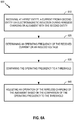
- FIG. 6A provides a flowchart of an exemplary method 600 for wireless charging, in accordance with one or more aspects of the present disclosure.
- the method 600 is described herein with reference to a particular order, in various implementations, the step(s) or feature(s) herein may be performed in a different order, or may be omitted, or may include additional step(s)/features(s).
- the method 600 may be operable by a first entity (e.g., an IPT receiver, such as an electric vehicle) for frequency protection during wireless charging or alignment with a second entity (e.g., an IPT transmitter).
- a first entity e.g., an IPT receiver, such as an electric vehicle
- a second entity e.g., an IPT transmitter
- the method 600 may involve, at 610, receiving a current wirelessly from the second entity via electromagnetic induction during the wireless charging or the alignment with the second entity.
- block 610 may be performed by the receive antenna 218 and the receive circuitry 210 of FIG. 2A .
- block 610 may be performed by the antenna/coil 352 of the transmit/receive circuitry 350 of FIG. 3 .
- the method 600 may involve, at 620, determining an operating frequency of the received current or an induced voltage (i.e., induced by the electromagnetic induction).
- Block 620 may involve, for example, generating a measurement waveform from the received current or induced voltage, the measurement waveform indicative of an operating frequency of the received current or the induced voltage.
- block 620 may be performed by the current transformer 252 and/or the edge detector 254 of FIG. 2B .
- the method 600 may involve, at 630, comparing the operating frequency to a threshold.
- Block 630 may involve, for example, comparing the operating frequency to a nominal frequency to determine an error value between the operating and nominal frequencies.
- the method 600 may involve, at 640, adjusting an operation of the wireless charging of the alignment based on the comparison at block 630.
- Block 640 may involve, for example, continuing the charging or the alignment in response to a difference between the operating frequency and the threshold being less than or equal to a first tolerance level, and/or stopping or refusing the charging or the alignment in response to the difference being greater than the first tolerance level.
- blocks 630 and 640 may be performed by the reference clock 256 and/or the microcontroller 264 of FIG. 2B .
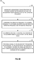
- FIGs. 6B-C show further operations or aspects of method 600 that are optional are not required to perform the method 600. If the method 600 includes at least one block of FIGs. 6B-C , then the method 600 may terminate after the at least one block, without necessarily having to include any subsequent downstream block(s) that may be illustrated.
- block 620 may involve, at 650, determining the operating frequency involves generating a measurement waveform from the received current or the induced voltage, the measurement waveform indicative of the operating frequency.
- block 650 may be performed by the current transformer 252 and/or the edge detector 254 of FIG. 2B or the like.
- block 630 may involve, at 660, comparing the operating frequency to a nominal frequency to determine an error value between the operating frequency and the nominal frequency.
- Block 640 may involve, at 662, determining whether to continue the charging or the alignment based at least in part on the error value.
- blocks 660 and 662 may be performed by the reference clock 256 and/or the microcontroller 264 of FIG. 2B or the like.
- method 600 may further involve, at 670, providing a signal to the second entity regarding the adjustment to the operation of the charging or the alignment, wherein the signal may indicate a fault condition associated with the operation of the charging or the alignment.
- block 670 may be performed by the antenna/coil 352 of the transmit/receive circuitry 350 of FIG. 3 coupled to the measurement circuit 250 of FIG. 2B , or the like.
- block 600 may involve, at 680, receiving a first current during the charging and a second current during the alignment.
- Block 620 may involve, at 682, generating a first measurement waveform from the first current, the first measurement waveform indicative of a first operating frequency of the first current, as well as, at 684, generating a second measurement waveform from the received second current, the second measurement waveform indicative of a second operating frequency of the second current.
- the method 600 may further involve, at 686, comparing the first and second operating frequencies to determine an error value between the first and second operating frequencies, as well as, at 688, determining whether to continue the charging or the alignment based at least in part on the error value.
- Block 688 may involve, at 690, continuing the charging or the alignment in response to the error value being less than or equal to a second tolerance level for a difference between the first and second operating frequencies, as well as, at 692, stopping or refusing the charging or the alignment in response to the error value being greater than the second tolerance level.
- block 680 may be performed by the current transformer 252 and/or the edge detector 254 of FIG. 2B or the like
- blocks 682 and 684 may be performed by the current transformer 252 and/or the edge detector 254 of FIG. 2B or the like
- blocks 686, 688, 690, and 692 may be performed by the reference clock 256 and/or the microcontroller 264 of FIG. 2B or the like.
- FIG. 7 is a flowchart depicting an exemplary implementation of a method 700 for frequency protection during an alignment operation, in accordance with one or more aspects of the present disclosure.
- the method 700 may involve, at 710, starting an alignment process with a charging unit and a receiving unit.
- block 710 may be performed by the receiver 408 onboard the vehicle 401 of FIGs. 4A-E and FIG. 5 to start an alignment with a charging unit (e.g., the transmitter 404).
- block 710 may be performed by the transmitter 404 of a charging station or the like coupled to the base pad 506 and the powerback bone 502 (see FIGs. 4A-E and FIG. 5 ), wherein the transmitter 404 may be configured to start an alignment with the receiving unit (e.g., the receiver 408).
- the method 700 may involve, at 720, measuring a frequency of a current received via IPT.
- block 720 may be performed by the current transformer 252 and/or the edge detector 254 of FIG. 2B or the like.
- the method 700 may involve, at 730, comparing the measured frequency of the received current or induced voltage to a known/nominal frequency.
- the method 700 may involve, at 740, determining whether the difference/error between the measured frequency and the nominal frequency is greater than a tolerance level/range, such as, for example, about 5% or other percentage defined by the user/administrator and/or the particular application of the method 700.
- blocks 730 and 740 may be performed by the reference clock 256 and/or the microcontroller 264 of FIG. 2B or the like.
- the method 700 may involve, at 750, continuing the alignment if the difference/error between the measured frequency and the nominal frequency is not greater than the tolerance level/range.
- the method 700 may involve, at 760, refusing the alignment or stopping the alignment if the difference/error between the measured frequency and the nominal frequency is greater than the tolerance level/range.
- the method 700 may optionally involve comparing the measured frequency with a corresponding frequency measured during the charging process, and determining whether to continue or stop the alignment process based at least in part on a difference/error between the frequencies measured during the alignment and charging processes.
- blocks 750 and/or 760 may be performed by the receiver 408 of FIGs. 4A-E and FIG.
- blocks 750 and/or 760 may be performed by the transmitter 404 of FIGs. 4A-E and FIG. 5 that is in operative communication with the receiver 408.
- FIG. 8 is a flowchart depicting another exemplary implementation of a method 800 for frequency protection during a wireless charging operation, in accordance with one or more aspects of the present disclosure.
- the method 800 may involve, at 810, starting a charging process with a charging unit and a receiving unit.
- block 810 may be performed by the receiver 408 onboard the vehicle 401 of FIGs. 4A-E and FIG. 5 to start an alignment with a charging unit (e.g., the transmitter 404).
- block 810 may be performed by the transmitter 404 of a charging station or the like coupled to the base pad 506 and the powerback bone 502 (see FIGs. 4A-E and FIG. 5 ), wherein the transmitter 404 may be configured to start an alignment with the receiving unit (e.g., the receiver 408).
- the method 800 may involve, at 820, measuring a frequency of a current received via IPT.
- block 820 may be performed by the current transformer 252 and/or the edge detector 254 of FIG. 2B or the like.
- the method 800 may involve, at 830, comparing the measured frequency of the received current or induced voltage to a known/nominal frequency.
- the method 800 may involve, at 840, determining whether the difference/error between the measured frequency and the nominal frequency is greater than a tolerance level/range, such as, for example, about 5% or the like.
- blocks 830 and 840 may be performed by the reference clock 256 and/or the microcontroller 264 of FIG. 2B or the like.
- the method 800 may involve, at 850, continuing the charging if the difference/error between the measured frequency and the nominal frequency is not greater than the tolerance level/range.
- the method 800 may involve, at 860, shutting down the IPT system or stopping the charging if the difference/error between the measured frequency and the nominal frequency is greater than the tolerance level/range.
- the method 800 may optionally involve comparing the measured frequency with a corresponding frequency measured during the alignment process, and determining whether to continue or stop the charging process based at least in part on a difference/error between the frequencies measured during the charging and alignment processes.
- blocks 850 and/or 860 may be performed by the receiver 408 of FIGs. 4A-E and FIG.
- blocks 850 and/or 860 may be performed by the transmitter 404 of FIGs. 4A-E and FIG. 5 that is in operative communication with the receiver 408.
- any suitable means capable of performing the operations such as various hardware and/or software component(s), circuits, and/or module(s).
- any operations illustrated in the Figures may be performed by corresponding functional means capable of performing the operations.
- means for receiving a current wirelessly at a first entity from a second entity via electromagnetic induction during the charging or alignment with the second entity, and/or means for receiving a first current during the charging and means for receiving a second current during the alignment may comprise, for example, the antenna/coil 352 of the transmit/receive circuitry 350 of FIG. 3 coupled to the measurement circuit 250 of FIG. 2B .
- means for determining an operating frequency of the received current or a voltage induced by the electromagnetic induction, means for generating a measurement waveform from the received current or the induced voltage, means for generating a first measurement waveform from the first current, and/or means for generating a second measurement waveform from the second current may comprise, for example, the current transformer 252 and/or the edge detector 254 of FIG. 2B .
- means for comparing the frequency to a threshold and/or means for comparing the operating frequency to a nominal frequency to determine an error value between the operating frequency and the nominal frequency may comprise, for example, the reference clock 256 and/or the microcontroller 264 of FIG. 2B .
- means for comparing the first and second operating frequencies to determine an error value between the first and second operating frequencies and/or means for determining whether to continue the charging or the alignment based at least in part on the error value may comprise, for example, the reference clock 256 and/or the microcontroller 264 of FIG. 2B .
- means for adjusting an operation of the charging or the alignment based on the comparison or the error value may comprise, for example, the receiver 408 of FIGs. 4A-E and FIG. 5 .
- the means for adjusting the operation of the charging or the alignment, and/or aspects thereof as listed above may comprise the transmitter 404 of FIGs. 4A-E and FIG. 5 that is in operative communication with the receiver 408.
- means for providing a signal to the second entity regarding the adjustment to the operation of the charging or the alignment may comprise, for example, the antenna/coil 352 of the transmit/receive circuitry 350 of FIG. 3 .
- Information and signals may be represented using any of a variety of different technologies and techniques.
- data, instructions, commands, information, signals, bits, symbols, and chips that may be referenced throughout the above description may be represented by voltages, currents, electromagnetic waves, magnetic fields or particles, optical fields or particles, or any combination thereof.
- DSP Digital Signal Processor
- ASIC Application Specific Integrated Circuit
- FPGA Field Programmable Gate Array
- a general purpose processor may be a microprocessor, but in the alternative, the processor may be any conventional processor, controller, microcontroller, or state machine.
- a processor may also be implemented as a combination of computing devices, e.g., a combination of a DSP and a microprocessor, a plurality of microprocessors, one or more microprocessors in conjunction with a DSP core, or any other such configuration.
- a software module may reside in Random Access Memory (RAM), flash memory, Read Only Memory (ROM), Electrically Programmable ROM (EPROM), Electrically Erasable Programmable ROM (EEPROM), registers, hard disk, a removable disk, a CD ROM, or any other form of storage medium known in the art.
- RAM Random Access Memory
- ROM Read Only Memory
- EPROM Electrically Programmable ROM
- EEPROM Electrically Erasable Programmable ROM
- registers hard disk, a removable disk, a CD ROM, or any other form of storage medium known in the art.
- a storage medium is coupled to the processor such that the processor may read information from, and write information to, the storage medium.
- the storage medium may be integral to the processor.
- Disk and disc includes compact disc (CD), laser disc, optical disc, digital versatile disc (DVD), floppy disk and blu ray disc where disks usually reproduce data magnetically, while discs reproduce data optically with lasers. Combinations of the above should also be included within the scope of computer readable media.
- the processor and the storage medium may reside in an ASIC.
- the ASIC may reside in a user terminal.
- the processor and the storage medium may reside as discrete components in a user terminal.
Landscapes
- Engineering & Computer Science (AREA)
- Power Engineering (AREA)
- Transportation (AREA)
- Mechanical Engineering (AREA)
- Computer Networks & Wireless Communication (AREA)
- Life Sciences & Earth Sciences (AREA)
- Sustainable Development (AREA)
- Sustainable Energy (AREA)
- Charge And Discharge Circuits For Batteries Or The Like (AREA)
- Current-Collector Devices For Electrically Propelled Vehicles (AREA)
- Electric Propulsion And Braking For Vehicles (AREA)
Claims (15)
- Procédé (600) exploitable par une première entité (108, 208, 408) pour contrôler la charge sans fil, comprenant les étapes consistant à :
recevoir par voie hertzienne (610) un courant à partir d'une deuxième entité (104, 204, 404) par induction électromagnétique pendant la charge de la première entité ; et caractérisé par les étapes consistant à :déterminer (620) une fréquence de fonctionnement du courant reçu induit par l'induction électromagnétique ;déterminer (630) une première valeur d'erreur entre la fréquence de fonctionnement et une fréquence cible ; etrégler (640) une opération de charge sur la base de la comparaison en continuant la charge en réponse au fait que la première valeur d'erreur est inférieure à ou égal à un premier niveau de tolérance, et en arrêtant la charge en réponse au fait que la première valeur d'erreur est supérieure au premier niveau de tolérance. - Procédé selon la revendication 1, dans lequel la détermination de la fréquence de fonctionnement comprend l'étape consistant à générer (650) une forme d'onde de mesure à partir du courant reçu, la forme d'onde de mesure fournissant une indication de la fréquence de fonctionnement.
- Procédé selon la revendication 1, comprenant en outre l'étape consistant à fournir (670) un signal à la deuxième entité (104, 204, 404) concernant le réglage du fonctionnement de la charge.
- Procédé selon la revendication 1, dans lequel l'étape consistant à recevoir le courant comprend la réception (680) d'un premier courant pendant la charge et d'un second courant pendant l'alignement de la première entité avec la deuxième entité.
- Appareil de contrôle de charge sans fil entre une première entité (108, 208, 408) et une deuxième entité (104, de 104, 404), comprenant :
des moyens pour recevoir par voie hertzienne (610) un courant à partir de la deuxième entité par induction électromagnétique pendant la charge de la première entité ; et caractérisé par :des moyens pour déterminer (620) une fréquence de fonctionnement du courant reçu induit par l'induction électromagnétique ;des moyens pour déterminer (630) une première valeur d'erreur entre la fréquence de fonctionnement et une fréquence cible ; etdes moyens pour régler (640) une opération de charge sur la base de la comparaison, les moyens pour régler comprenant des moyens pour continuer la charge en réponse au fait que la première valeur d'erreur est inférieure à ou égal à un premier niveau de tolérance, les moyens pour régler comprenant en outre des moyens pour arrêter la charge en réponse au fait que la première valeur d'erreur est supérieure au premier niveau de tolérance. - L'appareil selon la revendication 5, dans lequel les moyens pour recevoir comprennent un circuit de communication de récepteur (210), les moyens pour déterminer une fréquence de fonctionnement comprennent un circuit de mesures de fréquence (233), les moyens pour déterminer une première valeur d'erreur et les moyens pour régler un fonctionnement de la charge comprennent un contrôleur (264).
- L'appareil selon la revendication 5 ou la revendication 6, dans lequel les moyens pour déterminer la fréquence de fonctionnement comprennent des moyens pour générer une forme d'onde de mesure à partir du courant reçu, la forme d'onde de mesure fournissant une indication de la fréquence de fonctionnement.
- Appareil selon la revendication 6, dans lequel le premier niveau de tolérance comprend une différence de 5% entre la fréquence de fonctionnement et la fréquence cible.
- Appareil selon la revendication 5 ou la revendication 6, comprenant en outre des moyens pour fournir un signal à la deuxième entité concernant le réglage de l'opération de charge.
- Appareil selon la revendication 9, dans lequel le signal indique une condition de défaillance associée au fonctionnement de l'opération de charge.
- Appareil selon la revendication 5 ou la revendication 6, dans lequel les moyens pour recevoir le courant comprennent des moyens pour recevoir un premier courant pendant la charge et des moyens pour recevoir un deuxième courant pendant l'alignement de la première entité avec la deuxième entité.
- L'appareil selon la revendication 11, dans lequel les moyens pour déterminer la fréquence de fonctionnement comprennent :des moyens pour générer (682) une première forme d'onde de mesure à partir du premier courant, la première forme d'onde de mesure fournissant une indication d'une première fréquence de fonctionnement du premier courant ; etdes moyens pour générer (684) une deuxième forme d'onde de mesure à partir du deuxième courant, la deuxième forme d'onde de mesure fournissant une indication d'une deuxième fréquence de fonctionnement du deuxième courant.
- L'appareil selon la revendication 12, comprenant en outre :des moyens pour comparer (686) la première et la deuxième fréquence de fonctionnement pour déterminer une deuxième valeur d'erreur entre la première et la deuxième fréquence de fonctionnement ; etdes moyens pour déterminer (688) si il faut continuer la charge sur la base, au moins en partie, de la deuxième valeur d'erreur.
- L'appareil selon la revendication 13, dans lequel les moyens pour déterminer s'il faut continuer la charge sur la base, au moins en partie, de la deuxième valeur d'erreur comprennent :des moyens pour continuer (690) la charge en réponse au fait que la deuxième valeur d'erreur est inférieure à ou égal à un deuxième niveau de tolérance pour une différence entre la première et la deuxième fréquence de fonctionnement ; etdes moyens pour arrêter (692) la charge en réponse au fait que la deuxième valeur d'erreur est supérieure au deuxième niveau de tolérance.
- L'appareil selon la revendication 6, dans lequel la première entité comprend un récepteur à transfert d'énergie par induction, IPT, et la deuxième entité comprend un émetteur IPT ; ou dans lequel la première entité comprend un émetteur à transfert d'énergie par induction, IPT, et la deuxième entité comprend un récepteur IPT.
Applications Claiming Priority (3)
| Application Number | Priority Date | Filing Date | Title |
|---|---|---|---|
| US201461968255P | 2014-03-20 | 2014-03-20 | |
| US14/555,380 US9680331B2 (en) | 2014-03-20 | 2014-11-26 | System and method for frequency protection in wireless charging |
| PCT/US2015/020760 WO2015142734A1 (fr) | 2014-03-20 | 2015-03-16 | Système et procédé de protection de fréquence en charge sans fil |
Publications (2)
| Publication Number | Publication Date |
|---|---|
| EP3132518A1 EP3132518A1 (fr) | 2017-02-22 |
| EP3132518B1 true EP3132518B1 (fr) | 2018-06-27 |
Family
ID=54143011
Family Applications (1)
| Application Number | Title | Priority Date | Filing Date |
|---|---|---|---|
| EP15712027.0A Active EP3132518B1 (fr) | 2014-03-20 | 2015-03-16 | Système et procédé de protection de fréquence lors de la charge sans contact |
Country Status (6)
| Country | Link |
|---|---|
| US (1) | US9680331B2 (fr) |
| EP (1) | EP3132518B1 (fr) |
| JP (1) | JP6457548B2 (fr) |
| KR (1) | KR20160135223A (fr) |
| CN (1) | CN106132754B (fr) |
| WO (1) | WO2015142734A1 (fr) |
Families Citing this family (10)
| Publication number | Priority date | Publication date | Assignee | Title |
|---|---|---|---|---|
| US9725003B2 (en) * | 2011-08-06 | 2017-08-08 | Delphi Technologies, Inc. | Wireless battery charging system varying magnetic field frequency to maintain a desired voltage-current phase relationship |
| KR102373925B1 (ko) * | 2015-05-18 | 2022-03-15 | 삼성전자주식회사 | 무선 충전 운용 방법 및 이를 지원하는 전자 장치 |
| US10059213B2 (en) | 2015-11-13 | 2018-08-28 | Nio Usa, Inc. | Charging devices within wheel portions |
| US10093195B2 (en) | 2015-11-13 | 2018-10-09 | Nio Usa, Inc. | Integrated vehicle charging panel system and method of use |
| US10336194B2 (en) * | 2015-11-13 | 2019-07-02 | Nio Usa, Inc. | Electric vehicle charging device alignment and method of use |
| US10124690B2 (en) | 2015-11-13 | 2018-11-13 | Nio Usa, Inc. | Electric vehicle charging device positioning and method of use |
| US11207989B2 (en) | 2016-03-22 | 2021-12-28 | University Of Georgia Research Foundation, Inc. | Wireless charging of electric vehicles |
| US10461587B2 (en) * | 2016-09-19 | 2019-10-29 | Witricity Corporation | Methods and apparatus for positioning a vehicle using foreign object detection |
| CN106953302B (zh) * | 2017-03-07 | 2021-01-22 | 河北博宏感应技术股份有限公司 | 一种频率保护电路 |
| KR20210130084A (ko) * | 2020-04-21 | 2021-10-29 | 삼성전자주식회사 | 배터리를 무선 충전하기 위한 전자 장치 |
Family Cites Families (14)
| Publication number | Priority date | Publication date | Assignee | Title |
|---|---|---|---|---|
| JP3416863B2 (ja) * | 1994-06-27 | 2003-06-16 | 松下電工株式会社 | 電源装置 |
| US8004235B2 (en) * | 2006-09-29 | 2011-08-23 | Access Business Group International Llc | System and method for inductively charging a battery |
| JP5459058B2 (ja) * | 2009-11-09 | 2014-04-02 | 株式会社豊田自動織機 | 共鳴型非接触電力伝送装置 |
| US9203380B2 (en) | 2010-12-29 | 2015-12-01 | National Semiconductor Corporation | Resonance tuning |
| JP5071574B1 (ja) | 2011-07-05 | 2012-11-14 | ソニー株式会社 | 検知装置、受電装置、非接触電力伝送システム及び検知方法 |
| WO2013031025A1 (fr) * | 2011-09-02 | 2013-03-07 | 富士通株式会社 | Relais de puissance |
| KR101781650B1 (ko) | 2011-10-04 | 2017-09-26 | 삼성전자주식회사 | 무선 다중 충전을 위한 방법 및 전력 송신기 |
| JP2014534801A (ja) * | 2011-10-25 | 2014-12-18 | キム ソンソプKIM, Seon Seob | 無接点充電システム及び無接点充電方法 |
| WO2013088488A1 (fr) | 2011-12-12 | 2013-06-20 | トヨタ自動車株式会社 | Système de transmission et de réception électrique sans contact, véhicule et dispositif de transmission électrique |
| EP2870676B1 (fr) | 2012-07-05 | 2016-09-21 | Powermat Technologies Ltd. | Système et procédé d'alimentation d'énergie d'induction à des niveaux de puissance multiples |
| US9859755B2 (en) | 2012-07-16 | 2018-01-02 | Qualcomm Incorporated | Device alignment and identification in inductive power transfer systems |
| JP5888201B2 (ja) * | 2012-10-03 | 2016-03-16 | 株式会社豊田自動織機 | 受電機器、及び非接触電力伝送装置 |
| KR101615669B1 (ko) | 2012-10-11 | 2016-05-11 | 파워매트 테크놀로지스 엘티디. | 디지털 메시지들을 동시에 송신하기 위한 유도 전력 송신 시스템 및 방법 |
| US9496744B2 (en) * | 2012-12-20 | 2016-11-15 | Intel Corporation | Wireless charging optimization utilizing an NFC module that detects induced current and provides an indication of induced current |
-
2014
- 2014-11-26 US US14/555,380 patent/US9680331B2/en active Active
-
2015
- 2015-03-16 WO PCT/US2015/020760 patent/WO2015142734A1/fr active Application Filing
- 2015-03-16 CN CN201580015230.8A patent/CN106132754B/zh active Active
- 2015-03-16 EP EP15712027.0A patent/EP3132518B1/fr active Active
- 2015-03-16 KR KR1020167026780A patent/KR20160135223A/ko unknown
- 2015-03-16 JP JP2016555577A patent/JP6457548B2/ja active Active
Non-Patent Citations (1)
| Title |
|---|
| None * |
Also Published As
| Publication number | Publication date |
|---|---|
| WO2015142734A1 (fr) | 2015-09-24 |
| JP2017516436A (ja) | 2017-06-15 |
| CN106132754B (zh) | 2019-04-26 |
| KR20160135223A (ko) | 2016-11-25 |
| CN106132754A (zh) | 2016-11-16 |
| EP3132518A1 (fr) | 2017-02-22 |
| US9680331B2 (en) | 2017-06-13 |
| US20150270739A1 (en) | 2015-09-24 |
| JP6457548B2 (ja) | 2019-01-23 |
Similar Documents
| Publication | Publication Date | Title |
|---|---|---|
| EP3132518B1 (fr) | Système et procédé de protection de fréquence lors de la charge sans contact | |
| EP3031117B1 (fr) | Système et procédé d'alignement et de détection de compatibilité pour un système de transfert de puissance sans fil | |
| EP2873132B1 (fr) | Circuit et procédé d'accord destinés à des systèmes de transfert d'énergie sans fil | |
| EP3096972B1 (fr) | Systèmes et procédés pour alignement de bobine d'induction de véhicule électrique | |
| EP3311464B1 (fr) | Dispositifs, systèmes et procédés d'utilisation d'une injection de puissance réactive pour des systèmes de charge de véhicule électrique à réglage actif | |
| US9931952B2 (en) | Electric vehicle wireless charging with monitoring of duration of charging operational mode | |
| US9352661B2 (en) | Induction power transfer system with coupling and reactance selection | |
| US9859755B2 (en) | Device alignment and identification in inductive power transfer systems | |
| US10566850B2 (en) | Apparatus and methods for reducing magnetic field emissions between wireless power transmitters | |
| US10083792B2 (en) | System, method and apparatus for reducing the height of bipolar transmitters and/or receivers in electric vehicle charging | |
| US9505315B2 (en) | Wireless charging based on selective activation of transmit antennas | |
| US9859955B2 (en) | System and method for power output control in wireless power transfer systems | |
| US20140054971A1 (en) | Power supply control in wireless power transfer systems | |
| EP3350899B1 (fr) | Méthode et dispositif utilisant une assistance multifilaire pour l'alignement lors du tranfert de puissance inductif |
Legal Events
| Date | Code | Title | Description |
|---|---|---|---|
| STAA | Information on the status of an ep patent application or granted ep patent |
Free format text: STATUS: THE INTERNATIONAL PUBLICATION HAS BEEN MADE |
|
| PUAI | Public reference made under article 153(3) epc to a published international application that has entered the european phase |
Free format text: ORIGINAL CODE: 0009012 |
|
| STAA | Information on the status of an ep patent application or granted ep patent |
Free format text: STATUS: REQUEST FOR EXAMINATION WAS MADE |
|
| 17P | Request for examination filed |
Effective date: 20160727 |
|
| AK | Designated contracting states |
Kind code of ref document: A1 Designated state(s): AL AT BE BG CH CY CZ DE DK EE ES FI FR GB GR HR HU IE IS IT LI LT LU LV MC MK MT NL NO PL PT RO RS SE SI SK SM TR |
|
| AX | Request for extension of the european patent |
Extension state: BA ME |
|
| DAV | Request for validation of the european patent (deleted) | ||
| DAX | Request for extension of the european patent (deleted) | ||
| REG | Reference to a national code |
Ref country code: DE Ref legal event code: R079 Ref document number: 602015012731 Country of ref document: DE Free format text: PREVIOUS MAIN CLASS: H02J0005000000 Ipc: B60L0003000000 |
|
| GRAP | Despatch of communication of intention to grant a patent |
Free format text: ORIGINAL CODE: EPIDOSNIGR1 |
|
| RIC1 | Information provided on ipc code assigned before grant |
Ipc: B60L 11/18 20060101ALI20171221BHEP Ipc: H02J 7/00 20060101ALI20171221BHEP Ipc: B60L 3/04 20060101ALI20171221BHEP Ipc: H02J 50/80 20160101ALI20171221BHEP Ipc: H02J 5/00 20160101ALI20171221BHEP Ipc: H02J 50/12 20160101ALI20171221BHEP Ipc: H02J 50/90 20160101ALI20171221BHEP Ipc: H02J 7/02 20160101ALI20171221BHEP Ipc: B60L 3/00 20060101AFI20171221BHEP |
|
| STAA | Information on the status of an ep patent application or granted ep patent |
Free format text: STATUS: GRANT OF PATENT IS INTENDED |
|
| INTG | Intention to grant announced |
Effective date: 20180125 |
|
| GRAS | Grant fee paid |
Free format text: ORIGINAL CODE: EPIDOSNIGR3 |
|
| GRAA | (expected) grant |
Free format text: ORIGINAL CODE: 0009210 |
|
| STAA | Information on the status of an ep patent application or granted ep patent |
Free format text: STATUS: THE PATENT HAS BEEN GRANTED |
|
| AK | Designated contracting states |
Kind code of ref document: B1 Designated state(s): AL AT BE BG CH CY CZ DE DK EE ES FI FR GB GR HR HU IE IS IT LI LT LU LV MC MK MT NL NO PL PT RO RS SE SI SK SM TR |
|
| REG | Reference to a national code |
Ref country code: GB Ref legal event code: FG4D |
|
| REG | Reference to a national code |
Ref country code: AT Ref legal event code: REF Ref document number: 1011995 Country of ref document: AT Kind code of ref document: T Effective date: 20180715 |
|
| REG | Reference to a national code |
Ref country code: IE Ref legal event code: FG4D |
|
| REG | Reference to a national code |
Ref country code: DE Ref legal event code: R096 Ref document number: 602015012731 Country of ref document: DE |
|
| PG25 | Lapsed in a contracting state [announced via postgrant information from national office to epo] |
Ref country code: SE Free format text: LAPSE BECAUSE OF FAILURE TO SUBMIT A TRANSLATION OF THE DESCRIPTION OR TO PAY THE FEE WITHIN THE PRESCRIBED TIME-LIMIT Effective date: 20180627 Ref country code: LT Free format text: LAPSE BECAUSE OF FAILURE TO SUBMIT A TRANSLATION OF THE DESCRIPTION OR TO PAY THE FEE WITHIN THE PRESCRIBED TIME-LIMIT Effective date: 20180627 Ref country code: NO Free format text: LAPSE BECAUSE OF FAILURE TO SUBMIT A TRANSLATION OF THE DESCRIPTION OR TO PAY THE FEE WITHIN THE PRESCRIBED TIME-LIMIT Effective date: 20180927 Ref country code: FI Free format text: LAPSE BECAUSE OF FAILURE TO SUBMIT A TRANSLATION OF THE DESCRIPTION OR TO PAY THE FEE WITHIN THE PRESCRIBED TIME-LIMIT Effective date: 20180627 Ref country code: BG Free format text: LAPSE BECAUSE OF FAILURE TO SUBMIT A TRANSLATION OF THE DESCRIPTION OR TO PAY THE FEE WITHIN THE PRESCRIBED TIME-LIMIT Effective date: 20180927 |
|
| REG | Reference to a national code |
Ref country code: NL Ref legal event code: MP Effective date: 20180627 |
|
| REG | Reference to a national code |
Ref country code: LT Ref legal event code: MG4D |
|
| PG25 | Lapsed in a contracting state [announced via postgrant information from national office to epo] |
Ref country code: RS Free format text: LAPSE BECAUSE OF FAILURE TO SUBMIT A TRANSLATION OF THE DESCRIPTION OR TO PAY THE FEE WITHIN THE PRESCRIBED TIME-LIMIT Effective date: 20180627 Ref country code: LV Free format text: LAPSE BECAUSE OF FAILURE TO SUBMIT A TRANSLATION OF THE DESCRIPTION OR TO PAY THE FEE WITHIN THE PRESCRIBED TIME-LIMIT Effective date: 20180627 Ref country code: GR Free format text: LAPSE BECAUSE OF FAILURE TO SUBMIT A TRANSLATION OF THE DESCRIPTION OR TO PAY THE FEE WITHIN THE PRESCRIBED TIME-LIMIT Effective date: 20180928 Ref country code: HR Free format text: LAPSE BECAUSE OF FAILURE TO SUBMIT A TRANSLATION OF THE DESCRIPTION OR TO PAY THE FEE WITHIN THE PRESCRIBED TIME-LIMIT Effective date: 20180627 |
|
| REG | Reference to a national code |
Ref country code: AT Ref legal event code: MK05 Ref document number: 1011995 Country of ref document: AT Kind code of ref document: T Effective date: 20180627 |
|
| PG25 | Lapsed in a contracting state [announced via postgrant information from national office to epo] |
Ref country code: NL Free format text: LAPSE BECAUSE OF FAILURE TO SUBMIT A TRANSLATION OF THE DESCRIPTION OR TO PAY THE FEE WITHIN THE PRESCRIBED TIME-LIMIT Effective date: 20180627 |
|
| PG25 | Lapsed in a contracting state [announced via postgrant information from national office to epo] |
Ref country code: AT Free format text: LAPSE BECAUSE OF FAILURE TO SUBMIT A TRANSLATION OF THE DESCRIPTION OR TO PAY THE FEE WITHIN THE PRESCRIBED TIME-LIMIT Effective date: 20180627 Ref country code: EE Free format text: LAPSE BECAUSE OF FAILURE TO SUBMIT A TRANSLATION OF THE DESCRIPTION OR TO PAY THE FEE WITHIN THE PRESCRIBED TIME-LIMIT Effective date: 20180627 Ref country code: IS Free format text: LAPSE BECAUSE OF FAILURE TO SUBMIT A TRANSLATION OF THE DESCRIPTION OR TO PAY THE FEE WITHIN THE PRESCRIBED TIME-LIMIT Effective date: 20181027 Ref country code: SK Free format text: LAPSE BECAUSE OF FAILURE TO SUBMIT A TRANSLATION OF THE DESCRIPTION OR TO PAY THE FEE WITHIN THE PRESCRIBED TIME-LIMIT Effective date: 20180627 Ref country code: RO Free format text: LAPSE BECAUSE OF FAILURE TO SUBMIT A TRANSLATION OF THE DESCRIPTION OR TO PAY THE FEE WITHIN THE PRESCRIBED TIME-LIMIT Effective date: 20180627 Ref country code: PL Free format text: LAPSE BECAUSE OF FAILURE TO SUBMIT A TRANSLATION OF THE DESCRIPTION OR TO PAY THE FEE WITHIN THE PRESCRIBED TIME-LIMIT Effective date: 20180627 Ref country code: CZ Free format text: LAPSE BECAUSE OF FAILURE TO SUBMIT A TRANSLATION OF THE DESCRIPTION OR TO PAY THE FEE WITHIN THE PRESCRIBED TIME-LIMIT Effective date: 20180627 |
|
| PG25 | Lapsed in a contracting state [announced via postgrant information from national office to epo] |
Ref country code: ES Free format text: LAPSE BECAUSE OF FAILURE TO SUBMIT A TRANSLATION OF THE DESCRIPTION OR TO PAY THE FEE WITHIN THE PRESCRIBED TIME-LIMIT Effective date: 20180627 Ref country code: SM Free format text: LAPSE BECAUSE OF FAILURE TO SUBMIT A TRANSLATION OF THE DESCRIPTION OR TO PAY THE FEE WITHIN THE PRESCRIBED TIME-LIMIT Effective date: 20180627 Ref country code: IT Free format text: LAPSE BECAUSE OF FAILURE TO SUBMIT A TRANSLATION OF THE DESCRIPTION OR TO PAY THE FEE WITHIN THE PRESCRIBED TIME-LIMIT Effective date: 20180627 |
|
| REG | Reference to a national code |
Ref country code: DE Ref legal event code: R097 Ref document number: 602015012731 Country of ref document: DE |
|
| RAP2 | Party data changed (patent owner data changed or rights of a patent transferred) |
Owner name: WITRICITY CORPORATION |
|
| PLBE | No opposition filed within time limit |
Free format text: ORIGINAL CODE: 0009261 |
|
| STAA | Information on the status of an ep patent application or granted ep patent |
Free format text: STATUS: NO OPPOSITION FILED WITHIN TIME LIMIT |
|
| PG25 | Lapsed in a contracting state [announced via postgrant information from national office to epo] |
Ref country code: DK Free format text: LAPSE BECAUSE OF FAILURE TO SUBMIT A TRANSLATION OF THE DESCRIPTION OR TO PAY THE FEE WITHIN THE PRESCRIBED TIME-LIMIT Effective date: 20180627 |
|
| 26N | No opposition filed |
Effective date: 20190328 |
|
| PG25 | Lapsed in a contracting state [announced via postgrant information from national office to epo] |
Ref country code: SI Free format text: LAPSE BECAUSE OF FAILURE TO SUBMIT A TRANSLATION OF THE DESCRIPTION OR TO PAY THE FEE WITHIN THE PRESCRIBED TIME-LIMIT Effective date: 20180627 |
|
| PG25 | Lapsed in a contracting state [announced via postgrant information from national office to epo] |
Ref country code: MC Free format text: LAPSE BECAUSE OF FAILURE TO SUBMIT A TRANSLATION OF THE DESCRIPTION OR TO PAY THE FEE WITHIN THE PRESCRIBED TIME-LIMIT Effective date: 20180627 |
|
| REG | Reference to a national code |
Ref country code: CH Ref legal event code: PL |
|
| PG25 | Lapsed in a contracting state [announced via postgrant information from national office to epo] |
Ref country code: AL Free format text: LAPSE BECAUSE OF FAILURE TO SUBMIT A TRANSLATION OF THE DESCRIPTION OR TO PAY THE FEE WITHIN THE PRESCRIBED TIME-LIMIT Effective date: 20180627 Ref country code: LU Free format text: LAPSE BECAUSE OF NON-PAYMENT OF DUE FEES Effective date: 20190316 |
|
| REG | Reference to a national code |
Ref country code: BE Ref legal event code: MM Effective date: 20190331 |
|
| PG25 | Lapsed in a contracting state [announced via postgrant information from national office to epo] |
Ref country code: IE Free format text: LAPSE BECAUSE OF NON-PAYMENT OF DUE FEES Effective date: 20190316 Ref country code: CH Free format text: LAPSE BECAUSE OF NON-PAYMENT OF DUE FEES Effective date: 20190331 Ref country code: LI Free format text: LAPSE BECAUSE OF NON-PAYMENT OF DUE FEES Effective date: 20190331 |
|
| PG25 | Lapsed in a contracting state [announced via postgrant information from national office to epo] |
Ref country code: BE Free format text: LAPSE BECAUSE OF NON-PAYMENT OF DUE FEES Effective date: 20190331 |
|
| PG25 | Lapsed in a contracting state [announced via postgrant information from national office to epo] |
Ref country code: TR Free format text: LAPSE BECAUSE OF FAILURE TO SUBMIT A TRANSLATION OF THE DESCRIPTION OR TO PAY THE FEE WITHIN THE PRESCRIBED TIME-LIMIT Effective date: 20180627 |
|
| PG25 | Lapsed in a contracting state [announced via postgrant information from national office to epo] |
Ref country code: MT Free format text: LAPSE BECAUSE OF NON-PAYMENT OF DUE FEES Effective date: 20190316 Ref country code: PT Free format text: LAPSE BECAUSE OF FAILURE TO SUBMIT A TRANSLATION OF THE DESCRIPTION OR TO PAY THE FEE WITHIN THE PRESCRIBED TIME-LIMIT Effective date: 20181029 |
|
| PG25 | Lapsed in a contracting state [announced via postgrant information from national office to epo] |
Ref country code: CY Free format text: LAPSE BECAUSE OF FAILURE TO SUBMIT A TRANSLATION OF THE DESCRIPTION OR TO PAY THE FEE WITHIN THE PRESCRIBED TIME-LIMIT Effective date: 20180627 |
|
| PG25 | Lapsed in a contracting state [announced via postgrant information from national office to epo] |
Ref country code: HU Free format text: LAPSE BECAUSE OF FAILURE TO SUBMIT A TRANSLATION OF THE DESCRIPTION OR TO PAY THE FEE WITHIN THE PRESCRIBED TIME-LIMIT; INVALID AB INITIO Effective date: 20150316 |
|
| PG25 | Lapsed in a contracting state [announced via postgrant information from national office to epo] |
Ref country code: MK Free format text: LAPSE BECAUSE OF FAILURE TO SUBMIT A TRANSLATION OF THE DESCRIPTION OR TO PAY THE FEE WITHIN THE PRESCRIBED TIME-LIMIT Effective date: 20180627 |
|
| PGFP | Annual fee paid to national office [announced via postgrant information from national office to epo] |
Ref country code: FR Payment date: 20230327 Year of fee payment: 9 |
|
| PGFP | Annual fee paid to national office [announced via postgrant information from national office to epo] |
Ref country code: GB Payment date: 20230327 Year of fee payment: 9 Ref country code: DE Payment date: 20230329 Year of fee payment: 9 |
|
| PGFP | Annual fee paid to national office [announced via postgrant information from national office to epo] |
Ref country code: DE Payment date: 20240327 Year of fee payment: 10 Ref country code: GB Payment date: 20240327 Year of fee payment: 10 |