EP3132319B1 - Method for operating an automation arrangement - Google Patents
Method for operating an automation arrangement Download PDFInfo
- Publication number
- EP3132319B1 EP3132319B1 EP15717855.9A EP15717855A EP3132319B1 EP 3132319 B1 EP3132319 B1 EP 3132319B1 EP 15717855 A EP15717855 A EP 15717855A EP 3132319 B1 EP3132319 B1 EP 3132319B1
- Authority
- EP
- European Patent Office
- Prior art keywords
- computer program
- manipulator
- plc
- cell control
- input
- Prior art date
- Legal status (The legal status is an assumption and is not a legal conclusion. Google has not performed a legal analysis and makes no representation as to the accuracy of the status listed.)
- Active
Links
- 238000000034 method Methods 0.000 title claims description 53
- 238000004590 computer program Methods 0.000 claims description 105
- 230000008569 process Effects 0.000 claims description 25
- 238000013439 planning Methods 0.000 claims description 14
- 238000004891 communication Methods 0.000 claims description 11
- 238000005516 engineering process Methods 0.000 claims description 8
- 230000001419 dependent effect Effects 0.000 claims description 6
- 238000005538 encapsulation Methods 0.000 claims description 6
- 230000009466 transformation Effects 0.000 claims description 6
- 238000012800 visualization Methods 0.000 claims description 6
- 238000012913 prioritisation Methods 0.000 claims description 3
- 238000004519 manufacturing process Methods 0.000 claims description 2
- 238000004364 calculation method Methods 0.000 description 6
- 230000008901 benefit Effects 0.000 description 2
- 239000012636 effector Substances 0.000 description 2
- 230000003213 activating effect Effects 0.000 description 1
- 230000004913 activation Effects 0.000 description 1
- 238000006243 chemical reaction Methods 0.000 description 1
- 230000000295 complement effect Effects 0.000 description 1
- 238000003745 diagnosis Methods 0.000 description 1
- 230000000694 effects Effects 0.000 description 1
- 230000010354 integration Effects 0.000 description 1
- 230000003993 interaction Effects 0.000 description 1
- 238000005192 partition Methods 0.000 description 1
- 230000026676 system process Effects 0.000 description 1
Images


Classifications
-
- G—PHYSICS
- G05—CONTROLLING; REGULATING
- G05B—CONTROL OR REGULATING SYSTEMS IN GENERAL; FUNCTIONAL ELEMENTS OF SUCH SYSTEMS; MONITORING OR TESTING ARRANGEMENTS FOR SUCH SYSTEMS OR ELEMENTS
- G05B11/00—Automatic controllers
- G05B11/01—Automatic controllers electric
-
- G—PHYSICS
- G05—CONTROLLING; REGULATING
- G05B—CONTROL OR REGULATING SYSTEMS IN GENERAL; FUNCTIONAL ELEMENTS OF SUCH SYSTEMS; MONITORING OR TESTING ARRANGEMENTS FOR SUCH SYSTEMS OR ELEMENTS
- G05B19/00—Programme-control systems
- G05B19/02—Programme-control systems electric
- G05B19/04—Programme control other than numerical control, i.e. in sequence controllers or logic controllers
- G05B19/05—Programmable logic controllers, e.g. simulating logic interconnections of signals according to ladder diagrams or function charts
- G05B19/056—Programming the PLC
-
- G—PHYSICS
- G05—CONTROLLING; REGULATING
- G05B—CONTROL OR REGULATING SYSTEMS IN GENERAL; FUNCTIONAL ELEMENTS OF SUCH SYSTEMS; MONITORING OR TESTING ARRANGEMENTS FOR SUCH SYSTEMS OR ELEMENTS
- G05B19/00—Programme-control systems
- G05B19/02—Programme-control systems electric
- G05B19/18—Numerical control [NC], i.e. automatically operating machines, in particular machine tools, e.g. in a manufacturing environment, so as to execute positioning, movement or co-ordinated operations by means of programme data in numerical form
- G05B19/414—Structure of the control system, e.g. common controller or multiprocessor systems, interface to servo, programmable interface controller
- G05B19/4145—Structure of the control system, e.g. common controller or multiprocessor systems, interface to servo, programmable interface controller characterised by using same processor to execute programmable controller and numerical controller function [CNC] and PC controlled NC [PCNC]
-
- G—PHYSICS
- G05—CONTROLLING; REGULATING
- G05B—CONTROL OR REGULATING SYSTEMS IN GENERAL; FUNCTIONAL ELEMENTS OF SUCH SYSTEMS; MONITORING OR TESTING ARRANGEMENTS FOR SUCH SYSTEMS OR ELEMENTS
- G05B2219/00—Program-control systems
- G05B2219/30—Nc systems
- G05B2219/34—Director, elements to supervisory
- G05B2219/34287—Plc and motion controller combined
Definitions
- the invention relates to a method for operating an automation system according to the preamble of claim 1.
- PLCs Programmable logic controllers
- Such a functional element which can be controlled in principle by a programmable logic controller, is referred to both individually and in a combination here and below as an input-output module.
- these programmable logic controllers have been provided by dedicated equipment and electronic devices.
- Such programmable logic controllers regularly communicate via a bus, such. As a fieldbus, with the input-output module, they are set up to control.
- programmable logic controllers are also known whose functionality is provided by a computer program executed on a computer.
- a computer program can be referred to as a PLC computer program, wherein the system operated with such a PLC computer program can be referred to as a whole again as a soft PLC.
- a computer can also be connected to a field bus accordingly.
- extensions are also known by software of such a PLC computer program.
- Such a known extension can, for. B. serve to allow communication with a special device by a driver o. The like.
- expansion modules such as dynamic program libraries or dynamic-link libraries (DLLs) that can be addressed or included by the PLC computer program. So you are ultimately under the software control of the PLC computer program. A control of the programmable logic controller in software engineering sense by this extension is not provided.
- the WO 2005/059664 A2 relates to a method for controlling an automation arrangement, in which a motion manager synchronizes an NC control and a PLC control with each other, wherein all three components run as separate computer programs on a computing device.
- a controlled by a programmable logic controller input-output module to a manipulator in which, for. B. is a multi-axis robot is arranged.
- the input / output module may be located at the tool center point (TCP) of the manipulator.
- Such a manipulator is regularly controlled by a numerical control, here and hereinafter referred to as NC control, in its movements.
- NC control can in principle be provided by a computer program running on a computer.
- the input-output module to the manipulator are executed by the input-output module activities - which z. B. are specified by the PLC computer program - and the movements of the manipulator - which are in turn controlled by the NC control - in a close relationship.
- the object of the invention is to improve a method for operating an automation arrangement and in particular such an automation arrangement in which the functionality of a programmable logic controller is provided by a computer program, such that a better integration between the computer program for the programmable logic controller Control and an NC control for controlling a manipulator is possible.
- Essential for the invention is the realization that in addition to a PLC computer program for providing a programmable logic controller and this software superior on a computing device, a cell control computer program is provided, which controls the interface of the PLC computer program on the one hand for driving the input-output module and on the other hand provides the function of an NC control, in which case the control of the manipulator and other components is carried out by this cell control computer program itself.
- this cell control computer program forms the superordinate "roof" in the software engineering sense, which has all the necessary functions for the automation system including the PLC functionality under its control and in this way can coordinate these with one another.
- the functionality of the PLC computer program can be accessed in a modular fashion, wherein this PLC computer program can be introduced as an already existing component into the overall system.
- This standardization under the umbrella of the cell control computer program also makes it possible to provide a uniform interface of the system as a whole to the outside, which in turn makes it possible to control the automation arrangement in a uniform manner.
- the preferred embodiment according to the dependent claim 3 relates to advantageous bus systems for connecting the input-output modules and the manipulators to the computing device.
- the preferred embodiments of the dependent claims 6 to 8 in turn describe meaningful partitions of the PLC computer program or of the cell control computer program within an operating system and a process structure of the computer device.
- the dependent claim 9 describes advantageous possibilities of inter-process communication on the computing device between the cell control computer program and the PLC computer program, which in particular meet the synchronicity requirements of these two programs.
- the dependent claims 10 to 12 describe the configuration of an NC processor as part of the cell control computer program and its special interaction with the PLC computer program on the one hand and the control of the manipulator on the other.
- an object-oriented software architecture is used with great advantage in this control of the manipulator and other accesses.
- the proposed method is used to operate an automation system 1 with a manipulator 2a, b and an input-output module 3a, b, wherein the manipulator 2a, b and the input-output module 3a, b is set up for automated production.
- Such an automation arrangement 1 is in the Fig. 1 shown, in which case two manipulators 2a, b and two input-output modules 3a, b are provided, of which the input-output module 3b is a security module 4.
- This security module 4 may provide emergency stop functionality.
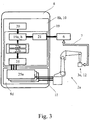
- In the Fig. 3 only one manipulator 2a and one input-output module 3a is shown.
- the automation arrangement 1 which is to be operated according to the proposed method, further comprises a computing device 5.
- the automation arrangement 1 may in particular be an automation cell 1a, ie a modular arrangement for automation within a larger automation system z. B. a larger factory.
- a PLC computer program 6 for providing a programmable logic controller for the input-output module 3a, b is executed on the computer device 5, wherein the PLC computer program 6 via a module bus 7 for driving the input-output module 3a, b with this is in communication technology.
- the proposed method is now characterized in that a cell control computer program 8 for controlling the PLC computer program 6 via a PLC interface 9 of the PLC computer program 6 is executed on the computer device 5 that the cell control computer program 9, an NC controller 10 for the Manipulator 2a, bterrorismterrorism and that the cell control computer program 8 via a network bus 11 for controlling the manipulator 2a, b communicates with this in telecommunications connection.
- the manipulator 2a, b may be a multi-axis manipulator, and in particular a six-axis manipulator.
- the computing device 5 can also consist of several individual computer units.
- both the PLC computer program 6 and the cell control computer program 8 can be constructed from a number of individual computer programs, each of which can also be executed in a separate process. Details will be described below.
- the input-output module 3a, b has an application device 12 arranged on the manipulator 2a, b.
- the input-output module 3a, b can also consist of such an application device 12.
- This application device 12 can in particular at the tool center point
- the manipulator 2a, b may be arranged and may preferably be a tool, a measuring device or a receptacle.
- the application device 12 can then be controlled in particular by the PLC computer program 6 by the activation of the input-output module 3a, b itself.
- the module bus 7 is a field bus 13.
- the network bus 11 may be an Ethernet bus 14, in which case a real-time Ethernet bus 14a may be used in particular.
- a real-time Ethernet bus 14a is an Ethernet bus according to a protocol that provides real-time capability.
- the cell control computer program 8 via the network bus 11 with a sensor device 15a, b in communication connection for reading the sensor device 15a, b is.
- the sensor device 15a is a line scanner and the sensor device 15b is a camera or a camera system, then each individual camera of the camera system can be designed differently.
- the automation assembly 1 and especially the automation cell 1a can - as already stated - with other automation arrangements together be part of a larger automation system, which z. B. is centrally controlled.
- the cell control computer program 8 provides a cell control interface via a factory bus 16 with which factory bus 16 the cell control computer program 8 is in telecommunications connection.
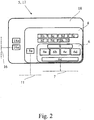
- a corresponding factory bus driver 16a is in the Fig. 2 shown.
- a central computer which controls a plurality of automation cells can also access the automation cell 1a and, in particular, the cell control computer program 8 on the computer device 5.
- the computing device 5 may be any computer-like device, such as specifically an industrial computer or other microprocessor system.
- the computer device 5 is a personal computer 17.
- the PLC computer program 6 and the cell control computer program 8 run on a multimedia operating system 18 for a personal computer 17.
- the PLC computer program 6 can be recognized, which implements various functional blocks, here the end effector function 6a, a feed system 6b of a tool, a workpiece database 6c and safety functions 6d.
- Each such function can be implemented by a separate module in the software technical sense.
- a module bus driver 6e is provided for the telecommunications connection with the module bus 7, a module bus driver 6e is provided.
- the interface to the outside - in the software technical sense - forms the already described above PLC interface. 9
- the cell control computer program 8 addresses the PLC computer program 6 via this PLC interface 9.
- the cell control computer program 8 also has a network bus driver 8a for communication with the network bus 11.
- Other particularly software-technical modules of the cell control computer program 8 are a visualization module 8b, a diagnosis module 8c, a robot module 8d, a normality sensor module 8e, a position sensor module 8f, a laser sensor module 8g and an NC module 8h. These modules communicate with each other. Furthermore, further modules can be provided.
- the PLC computer program 6 and the cell control computer program 8 are executed by different processes, respectively.
- the term process is to be understood here in the software technical sense. In this case, both the PLC computer program 6 and the cell control computer program 8 are each performed by a single process. However, it may also be that the PLC computer program 6 and the cell control computer program 8 are executed by a multiplicity of different processes.
- the division of the PLC computer program 6 and the cell control computer program 8 on the individual processes can be divided into the modules according to the representation of Fig. 2 or a similar distribution, but several modules can be grouped together and executed in a single process. It may also be that some modules are at least partially provided by the operating system, such as the driver.
- a preferred division of the cell control computer program 8 into different processes provides that an NC subcomputer program of the cell control computer program 8 for providing the NC controller 10 is executed in an NC process and that a manipulator subroutine of the cell control computer program 8 for Actuation of the manipulator 2a, b is performed in a manipulator process.
- the manipulator process is different from the NC process.
- the information obtained from the NC commands to control the manipulator 2a, b, ie "cleaned up" of the information for controlling the input-output module 3a, b, can then be processed by the manipulator subroutine.
- this NC subroutine for providing the NC controller 10 may - as shown in the Fig. 3 - to the NC module 8h the Fig. 2 and in the manipulator subroutine of the cell control computer program around the robot module 8d of the Fig. 2 act.
- the PLC interface 9 of the PLC computer program 6 can be addressed in principle by any programs and accordingly from different processes. On the one hand, it is addressed by the cell control computer program 8 for activating the input / output module 3a, b, on the other hand data is also made available for retrieval via the SPS interface 9, which is then provided by the visualization module 8b of the cell control computer program 8 can be displayed on a screen of the computing device 5.
- the computing device 5 provide multiple interprocess channels for communication with the PLC computer program 6, with at least partially different prioritization.
- prioritization means the order in which a corresponding communication is processed by the operating system via such an interprocess channel, responding more quickly to communication via an interprocess channel having a higher priority than to communication via an interprocess channel having a lower priority.
- a higher priority task may interrupt a currently processed lower priority task.
- this can be achieved by a single process providing the communication via the interprocess channels and processing these in dependence on the respective priority of the interprocess channels.
- each interprocess channel may be assigned to a process having a priority corresponding to the priority of the interprocess channel, in which case the respective process is processed according to its priority.
- the NC sub-computer program and a visualization program executed in a visualization process each communicate with the PLC computer program 6 via an inter-process channel, and the inter-process channel of the NC sub-computer program is prioritized higher than that of the visualization program. This takes into account the fact that the control by the NC sub-computer program is more important and should be carried out more quickly than a visualization.
- the cell control computer program 6 has an NC processor 19 for translating an NC program 20 into switching commands 21 for driving the input-output module 3a, b.
- the NC processor 19 can also be set up to compile the NC program 20 in geometry data 22a and / or in technology data 22b for controlling the manipulator 2a, b.
- the respective representation of Fig. 3 and the Fig. 4 is complementary insofar as that in the Fig. 3 in the first place the flow of data is represented and in the Fig. 4 the software technical structure of the interfaces is described.
- the NC processor 19 can consist of several modules, each of which is executed in its own process. Alternatively, the NC processor 19 can be executed in total in one process, which may in particular be the above NC process. Thus, the NC processor 19 may be the same as or included in the above NC sub-computer program. Consequently, the NC processor can also be formed by the above NC module 8h.
- the above NC program 20 is now a sequence of NC commands written in plain text. This is also called G-code.
- the G code may include G commands as well as M commands and general parameters.
- the NC processor 19 includes an NC interpreter 19 a and an NC command converter 19 b having access to a command database 23.
- NC interpreter 19a and NC command converter 19b translate the plaintext of the NC program 20 in geometry data 22a and / or technology data 22b on the one hand, for driving the manipulator 2a, b, and switching commands 21 for controlling the input-output module 3a, b on the other hand.
- the generation of the switching commands 21 can also be based on the technology data 22b.
- the NC program 20 can also include references or dependencies on sensor data, so that it is preferably provided that the NC processor 19 is also set up to translate the NC program 20 into sensor queries for reading the sensor device 15a, b.
- the NC processor 19 also includes an NC data collector 19c, which stores automatically generated data records in a protocol database 24 during the execution of the NC program.
- the NC processor 19 executes a path planning calculating routine 25 of the manipulator 2a, b based on the geometry data 22a and / or based on the technology data 22b.
- the path planning executed by the calculation routine 25 preferably comprises a kinematic transformation, that is to say a conversion of Cartesian coordinates into axis coordinates or vice versa.
- the path planning performed by the calculation routine 25 may also include interpolation.
- one or more position controllers 25a of the manipulator 2a can then be supplied with reference variables. This variant corresponds to the representation of Fig. 3 , Deviating from this representation, the calculation routine 25 can also be provided by the robot module 8d.
- this calculation routine 25 performs the above kinematics transformation, but not the path planning.
- a - not shown - robot control of the manipulator 2a, b supplied with the results of the kinematics transformation. Both the path planning and the functionality of the above position controllers 25a are then provided accordingly by this robot controller.
- the NC processor 19 executes the switching commands 21 in which the cell control computer program 8 - whose component is the NC processor 19 - is connected to the PLC interface 9 of the PLC.
- Computer program 6 accesses and the PLC computer program 6 to access the input-output module 3a, b via the module bus 7 drives.
- the NC processor 19 for controlling the manipulator 2a, b preferably also for reading out the sensor device 15a, b in particular also for carrying out the calculation routine 25 accesses an encapsulation interface 26 of the cell control computer program 8, and that access to the manipulator 2a, b via the network bus 11 is controlled. It is further preferred that if necessary also the sensor device 15a, b is read out via the network bus 11 and further, in particular also a path planning is performed on the access.
- Both this access to the encapsulation interface 26 and the access to the PLC interface 9 can be done by means of an object-oriented interface class. Therefore, it is preferred that access to the encapsulation interface 26 and / or the PLC interface 9 accesses an object-oriented interface class 27 of the type of a manipulator class 27a, an input-output module class 27b, a path planning class 27c and / or a sensor class 27d.
- an object-oriented interface class 27 of the type of a manipulator class 27a an input-output module class 27b, a path planning class 27c and / or a sensor class 27d.
- access to the PLC interface 9 may include access to the input-output module class 27b.
- the manipulator class 27a, the input-output module class 27b and / or the sensor class 27d are respectively implemented by a manipulator object 28a, an input-output module object 28b and a sensor object 28d which depends on Type of manipulator 2a, b of the input / output module 3a, b or the sensor device 15a, b is.
- the path planning class 27d may be implemented by a path planning object 28d, which is dependent on the particular algorithms with which path planning and especially interpolation and kinematics transformation is implemented.
Landscapes
- Engineering & Computer Science (AREA)
- Physics & Mathematics (AREA)
- General Physics & Mathematics (AREA)
- Automation & Control Theory (AREA)
- Human Computer Interaction (AREA)
- Manufacturing & Machinery (AREA)
- Numerical Control (AREA)
- Programmable Controllers (AREA)
- Control By Computers (AREA)
- Manipulator (AREA)
Description
Die Erfindung betrifft ein Verfahren zum Betrieb einer Automatisierungsanordnung gemäß dem Oberbegriff von Anspruch 1.The invention relates to a method for operating an automation system according to the preamble of
Aus dem Stand der Technik sind speicherprogrammierbare Steuerungen (SPS) bekannt, mit denen in der Automatisierungstechnik Aktoren, insbesondere Endeffektoren und Bereitstellungsysteme, sowie Sensoren und sonstige Funktionseinheiten einer Maschine oder Anlage programmiert und automatisch angesteuert werden können. Ein solches Funktionselement, welche durch eine speicherprogrammierbare Steuerung prinzipiell ansteuerbar ist, wird sowohl einzeln als auch in einer Kombination hier und nachfolgend allgemein als Ein-Ausgabe-Modul bezeichnet. Herkömmlicherweise wurden diese speicherprogrammierbaren Steuerungen durch speziell hierfür vorgesehene Geräte und elektronische Anordnungen bereitgestellt. Regelmäßig kommunizieren derartige speicherprogrammierbare Steuerungen über einen Bus, wie z. B. einem Feldbus, mit dem Ein-Ausgabemodul, zu dessen Ansteuerung sie eingerichtet sind.Programmable logic controllers (PLCs) are known from the prior art with which actuators, in particular end effectors and provision systems, as well as sensors and other functional units of a machine or system can be programmed and automatically controlled in automation technology. Such a functional element, which can be controlled in principle by a programmable logic controller, is referred to both individually and in a combination here and below as an input-output module. Conventionally, these programmable logic controllers have been provided by dedicated equipment and electronic devices. Such programmable logic controllers regularly communicate via a bus, such. As a fieldbus, with the input-output module, they are set up to control.
Mittlerweile sind auch speicherprogrammierbare Steuerungen bekannt, deren Funktionalität durch ein auf einem Computer ausgeführtes Computerprogramm bereitgestellt wird. Ein solches Computerprogramm kann als SPS-Computerprogramm bezeichnet werden, wobei das mit einem solchen SPS-Computerprogramm betriebene System insgesamt wiederum als Soft-SPS bezeichnet werden kann. Es ist also keine spezielle Hardware mehr für die speicherprogrammierbare Steuerung vorgesehen, sondern ihre Funktionalität wird durch ein Computerprogramm gebildet, welches auf einem herkömmlichen Computer oder auf einem auf die Automatisierungsumgebung zugeschnittenen Industrie-PC oder Embedded-PC abläuft. Zur Ansteuerung der Ein-Ausgabe-Module kann entsprechend ein solcher Computer ebenfalls an einen Feldbus angeschlossen sein.Meanwhile, programmable logic controllers are also known whose functionality is provided by a computer program executed on a computer. Such a computer program can be referred to as a PLC computer program, wherein the system operated with such a PLC computer program can be referred to as a whole again as a soft PLC. So there is no special hardware for the programmable logic controller provided, but their functionality is formed by a computer program which runs on a conventional computer or on an automation environment tailored industrial PC or embedded PC. To control the input-output modules, such a computer can also be connected to a field bus accordingly.
Aus dem Stand der Technik und speziell aus der
Die
Bei Automatisierungszellen als Bestandteil eines Automatisierungssystems kommt es regelmäßig vor, dass ein von einer speicherprogrammierbaren Steuerung angesteuertes Ein-Ausgabe-Modul an einem Manipulator, bei dem es sich z. B. um einen Mehrachsroboter handelt, angeordnet ist. Speziell kann das Ein-Ausgabe-Modul an dem Tool-Center-Point (TCP) des Manipulators angeordnet sein.In automation cells as part of an automation system, it happens regularly that a controlled by a programmable logic controller input-output module to a manipulator, in which, for. B. is a multi-axis robot is arranged. Specifically, the input / output module may be located at the tool center point (TCP) of the manipulator.
Ein solcher Manipulator wird regelmäßig durch eine numerische Steuerung, hier und nachfolgend als NC-Steuerung bezeichnet, in seinen Bewegungen angesteuert. Auch diese NC-Steuerung kann prinzipiell durch ein auf einem Computer ausgeführtes Computerprogramm bereitgestellt werden. Durch das Vorsehen des Ein-Ausgabe-Moduls an dem Manipulator stehen die von dem Ein-Ausgabe-Modul ausgeführten Tätigkeiten - welche z. B. von dem SPS-Computerprogramm vorgegeben werden - sowie die Bewegungen des Manipulators - die wiederum von der NC-Steuerung kontrolliert werden - in einem engen Zusammenhang.Such a manipulator is regularly controlled by a numerical control, here and hereinafter referred to as NC control, in its movements. This NC control can in principle be provided by a computer program running on a computer. By providing the input-output module to the manipulator are executed by the input-output module activities - which z. B. are specified by the PLC computer program - and the movements of the manipulator - which are in turn controlled by the NC control - in a close relationship.
Vor diesem Hintergrund besteht die Aufgabe der Erfindung darin, ein Verfahren zum Betrieb einer Automatisierungsanordnung und insbesondere einer solchen Automatisierungsanordnung, bei der die Funktionalität einer speicherprogrammierbaren Steuerung durch ein Computerprogramm bereitgestellt wird, dahin gehend zu verbessern, dass eine bessere Integration zwischen dem Computerprogramm für die speicherprogrammierbare Steuerung und einer NC-Steuerung für die Ansteuerung eines Manipulators ermöglicht wird.Against this background, the object of the invention is to improve a method for operating an automation arrangement and in particular such an automation arrangement in which the functionality of a programmable logic controller is provided by a computer program, such that a better integration between the computer program for the programmable logic controller Control and an NC control for controlling a manipulator is possible.
Das genannte Problem wird bei einem Verfahren zum Betrieb einer Automatisierungsanordnung mit den Merkmalen des Oberbegriffs von Anspruch 1 durch die Merkmale des kennzeichnenden Teils von Anspruch 1 gelöst.The above problem is solved in a method for operating an automation arrangement having the features of the preamble of
Wesentlich für die Erfindung ist die Erkenntnis, dass neben einem SPS-Computerprogramm zur Bereitstellung einer speicherprogrammierbaren Steuerung und dieser softwaretechnisch übergeordnet auf einer Rechnervorrichtung ein Zellkontroll-Computerprogramm vorgesehen ist, welches einerseits zur Ansteuerung des Ein-Ausgabe-Moduls die Schnittstelle des SPS-Computerprogramms ansteuert und andererseits die Funktion einer NC-Steuerung bereitstellt, wobei dann durch dieses Zellkontroll-Computerprogramm selbst die Ansteuerung des Manipulators und anderer Komponenten durchgeführt wird.Essential for the invention is the realization that in addition to a PLC computer program for providing a programmable logic controller and this software superior on a computing device, a cell control computer program is provided, which controls the interface of the PLC computer program on the one hand for driving the input-output module and on the other hand provides the function of an NC control, in which case the control of the manipulator and other components is carried out by this cell control computer program itself.
Mit anderen Worten bildet dieses Zellkontroll-Computerprogramm das im softwaretechnischen Sinne übergeordnete "Dach", welches alle notwendigen Funktionen für die Automatisierungsanordnung einschließlich der SPS-Funktionalität unter seiner Kontrolle hat und auf diese Weise diese untereinander koordinieren kann. Dabei kann modulartig auf die Funktionalität des SPS-Computerprogramms zugegriffen werden, wobei dieses SPS-Computerprogramm als bereits vorhandene Komponente in das Gesamtsystem eingebracht werden kann. Durch diese Vereinheitlichung unter dem Dach des Zellkontroll-Computerprogramms kann auch eine einheitliche Schnittstelle des Systems insgesamt nach außen bereitgestellt werden, welche wiederum die Ansteuerung der Automatisierungsanordnung auf einheitliche Art und Weise ermöglicht.In other words, this cell control computer program forms the superordinate "roof" in the software engineering sense, which has all the necessary functions for the automation system including the PLC functionality under its control and in this way can coordinate these with one another. In this case, the functionality of the PLC computer program can be accessed in a modular fashion, wherein this PLC computer program can be introduced as an already existing component into the overall system. This standardization under the umbrella of the cell control computer program also makes it possible to provide a uniform interface of the system as a whole to the outside, which in turn makes it possible to control the automation arrangement in a uniform manner.
Die bevorzugte Ausgestaltung nach dem Unteranspruch 3 betrifft vorteilhafte Bussysteme zur Anbindung der Ein-Ausgabe-Module sowie der Manipulatoren an die Rechnervorrichtung.The preferred embodiment according to the dependent claim 3 relates to advantageous bus systems for connecting the input-output modules and the manipulators to the computing device.
Die bevorzugten Ausgestaltungen der Unteransprüche 6 bis 8 wiederum beschreiben sinnvolle Aufteilungen des SPS-Computerprogramms bzw. des Zellkontroll-Computerprogramms innerhalb eines Betriebssystems und einer Prozessstruktur der Rechnervorrichtung.The preferred embodiments of the
Der Unteranspruch 9 beschreibt vorteilhafte Möglichkeiten der Interprozesskommunikation auf der Rechnervorrichtung zwischen dem Zellkontroll-Computerprogramm und dem SPS-Computerprogramm, welche insbesondere den Synchronizitätsanforderungen an diese beiden Programme gerecht werden.The
Die Unteransprüche 10 bis 12 beschreiben die Ausgestaltung eines NC-Verarbeiters als Bestandteil des Zellkontroll-Computerprogramms und sein spezielles Zusammenspiel mit dem SPS-Computerprogramm einerseits und der Ansteuerung des Manipulators andererseits.The dependent claims 10 to 12 describe the configuration of an NC processor as part of the cell control computer program and its special interaction with the PLC computer program on the one hand and the control of the manipulator on the other.
Wie die Unteransprüche 13 bis 15 beschreiben, wird bei dieser Ansteuerung des Manipulators und anderen Zugriffen mit großem Vorteil eine objektorientierte Softwarearchitektur eingesetzt.As described in subclaims 13 to 15, an object-oriented software architecture is used with great advantage in this control of the manipulator and other accesses.
Weitere Einzelheiten, Merkmale, Ziele und Vorteile der vorliegenden Erfindung werden nachfolgend anhand der Zeichnung eines bevorzugten Ausführungsbeispiels erläutert. In der Zeichnung zeigt
- Fig. 1
- eine schematische Darstellung einer Automatisierungsanordnung zur Ausführung des vorschlagsgemäßen Verfahrens,
- Fig. 2
- eine schematische Darstellung der Softwarestruktur auf der Rechnervorrichtung der Automatisierungsanordnung der
Fig. 1 , - Fig. 3
- eine schematische Darstellung des Datenflusses eines Zellkontroll-Computerprogramms gemäß der Automatisierungsanordnung der
Fig. 1 , - Fig. 4
- eine schematische Darstellung der Architektur des Zellkontroll-Computerprogramms der
Fig. 3 .
- Fig. 1
- a schematic representation of an automation arrangement for carrying out the proposed method,
- Fig. 2
- a schematic representation of the software structure on the computing device of the automation arrangement of
Fig. 1 . - Fig. 3
- a schematic representation of the data flow of a cell control computer program according to the automation arrangement of
Fig. 1 . - Fig. 4
- a schematic representation of the architecture of the cell control computer program of
Fig. 3 ,
Das vorschlagsgemäße Verfahren dient dem Betrieb einer Automatisierungsanordnung 1 mit einem Manipulator 2a, b und einem Ein-Ausgabe-Modul 3a, b, wobei der Manipulator 2a, b und das Ein-Ausgabe-Modul 3a, b jeweils zur automatisierten Fertigung eingerichtet ist.The proposed method is used to operate an
Eine solche Automatisierungsanordnung 1 ist in der
Die Automatisierungsanordnung 1, welche nach dem vorschlagsgemäßen Verfahren betrieben werden soll, weist ferner eine Rechnervorrichtung 5 auf. Bei der Automatisierungsanordnung 1 kann es sich insbesondere um eine Automatisierungszelle 1a handeln, also um eine modulare Anordnung zur Automatisierung innerhalb eines größeren Automatisierungssystems z. B. einer größeren Fabrik.The
Vorschlagsgemäß wird auf der Rechnervorrichtung 5 ein SPS-Computerprogramm 6 zur Bereitstellung einer speicherprogrammierbaren Steuerung für das Ein-Ausgabe-Modul 3a, b ausgeführt, wobei das SPS-Computerprogramm 6 über einen Modulbus 7 zur Ansteuerung des Ein-Ausgabe-Moduls 3a, b mit diesem in nachrichtentechnischer Verbindung steht.According to the proposal, a
Das vorschlagsgemäße Verfahren ist nun dadurch gekennzeichnet, dass auf der Rechnervorrichtung 5 ein Zellkontroll-Computerprogramm 8 zur Ansteuerung des SPS-Computerprogramms 6 über eine SPS-Schnittstelle 9 des SPS-Computerprogramms 6 ausgeführt wird, dass das Zellkontrollcomputerprogramm 9 eine NC-Steuerung 10 für den Manipulator 2a, b bereitstellt und dass das Zellkontroll-Computerprogramm 8 über einen Netzwerkbus 11 zur Ansteuerung des Manipulators 2a, b mit diesem in nachrichtentechnischer Verbindung steht.The proposed method is now characterized in that a cell
Bei dem Manipulator 2a, b kann es sich, wie vorliegend, um einen Mehrachsmanipulator, und insbesondere einen sechsachsigen Manipulator handeln. Die Rechnervorrichtung 5 kann auch aus mehreren einzelnen Rechnereinheiten bestehen. Ebenso kann sowohl das SPS-Computerprogramm 6, als auch das Zellkontrollcomputerprogramm 8 aus einer Reihe von einzelnen Computerprogrammen aufgebaut sein, die jeweils auch in einem eigenen Prozess ausgeführt werden können. Einzelheiten hierzu werden unten stehend beschrieben.As is the case here, the
In einer bevorzugten Ausführung weist das Ein-Ausgabe-Modul 3a, b eine an dem Manipulator 2a, b angeordnete Applikationsvorrichtung 12 auf. Es kann das Ein-Ausgabe-Modul 3a, b auch aus einer solchen Applikationsvorrichtung 12 bestehen. Diese Applikationsvorrichtung 12 kann insbesondere an dem Tool-Center-Point des Manipulators 2a, b angeordnet sein und es kann sich vorzugsweise dabei um ein Werkzeug, eine Messvorrichtung oder eine Aufnahme handeln. Die Applikationsvorrichtung 12 kann dann insbesondere durch das SPS-Computerprogramm 6 durch die Ansteuerung des Ein-Ausgabe-Moduls 3a, b selbst angesteuert werden.In a preferred embodiment, the input-
Weiter ist bevorzugt, dass der Modulbus 7 ein Feldbus 13 ist. Alternativ oder zusätzlich kann es sich bei dem Netzwerkbus 11 um einen Ethernetbus 14 handeln, wobei hierbei insbesondere ein Echtzeit-Ethernetbus 14a infrage kommt. Bei einem Echtzeit-Ethernetbus 14a handelt es sich um ein Ethernetbus nach einem Protokoll, welches eine Echtzeitfähigkeit bereitstellt.It is further preferred that the
Ebenso ist es bevorzugt, dass das Zellkontrollcomputerprogramm 8 über den Netzwerkbus 11 mit einer Sensorvorrichtung 15a, b in nachrichtentechnischer Verbindung zum Auslesen der Sensorvorrichtung 15a, b steht. Im Ausführungsbeispiel der
Die Automatisierungsanordnung 1 und speziell die Automatisierungszelle 1a kann - wie bereits festgestellt - mit anderen Automatisierungsanordnungen zusammen Bestandteil eines größeren Automatisierungssystems sein, welches z. B. zentral gesteuert wird. In so einem Fall ist bevorzugt vorgesehen, dass das Zellkontroll-Computerprogramm 8 eine Zellkontrollschnittstelle über einen Fabrikbus 16 bereitstellt, mit welchem Fabrikbus 16 das Zellkontroll-Computerprogramm 8 in nachrichtentechnischer Verbindung steht. Ein entsprechender Fabrikbustreiber 16a ist in der
Prinzipiell kann es sich bei der Rechnervorrichtung 5 um eine beliebige computerartige Vorrichtung handeln, so beispielsweise speziell um einen Industriecomputer oder ein sonstiges Mikroprozessorsystem. Bevorzugt ist allerdings, dass die Rechnervorrichtung 5 ein Personalcomputer 17 ist. Dies bietet die Möglichkeit, neben dem Zellkontrollcomputerprogramm 8 noch andere Computerprogramme flexibel auf der Rechnervorrichtung 5 auszuführen. Hier ist weiter bevorzugt, dass das SPS-Computerprogramm 6 und das Zellkontrollcomputerprogramm 8 auf einem Multimediabetriebssystem 18 für einen Personalcomputer 17 ablaufen.In principle, the computing device 5 may be any computer-like device, such as specifically an industrial computer or other microprocessor system. However, it is preferred that the computer device 5 is a personal computer 17. This offers the possibility in addition to the cell
Schematisch ist dieser Zusammenhang in der
Das Zellkontroll-Computerprogramm 8 spricht das SPS-Computerprogramm 6 über diese SPS-Schnittstelle 9 an. Das Zellkontrollcomputerprogramm 8 weist daneben einen Netzwerkbustreiber 8a für die nachrichtentechnische Verbindung mit dem Netzwerkbus 11 auf. Andere insbesondere softwaretechnische Module des Zellkontrollcomputerprogramms 8 sind ein Visualisierungsmodul 8b, ein Diagnosemodul 8c, ein Robotermodul 8d, ein Normalitätssensormodul 8e, ein Positionssensormodul 8f, ein Lasersensormodul 8g sowie ein NC-Modul 8h. Diese Module kommunizieren untereinander. Ferner können noch weitere Module vorgesehen sein.The cell
Außerhalb des Zellkontroll-Computerprogramms 8 und auf dem Betriebssystem, bei welchem es sich hier um das Multimediabetriebssystem 18 handelt, läuft nun wiederum - neben dem obigen Fabrikbustreiber 16a für die nachrichtentechnische Verbindung zum Fabrikbus 16 - ein Konfigurationsmodul 18a, welches z. B. den Zugriff zur Konfiguration auf das Zellkontroll-Computerprogramm 8 über eine herkömmliche Bedienoberfläche des Multimediabetriebssystems 18 erlaubt.Outside of the cell
Es ist weiter bevorzugt, dass das SPS-Computerprogramm 6 und das Zellkontroll-Computerprogramm 8 durch jeweils unterschiedliche Prozesse ausgeführt werden. Der Begriff Prozess ist hier im softwaretechnischen Sinne zu verstehen. Dabei kann sowohl das SPS-Computerprogramm 6 als auch das Zellkontroll-Computerprogramm 8 durch jeweils einen einzelnen Prozess ausgeführt werden. Es kann aber auch sein, dass das SPS-Computerprogramm 6 und das Zellkontrollcomputerprogramm 8 durch jeweils eine Vielzahl von unterschiedlichen Prozessen ausgeführt werden. Die Aufteilung des SPS-Computerprogramms 6 bzw. des Zellkontrollcomputerprogramms 8 auf die einzelnen Prozesse kann dabei der Aufteilung in die Module gemäß der Darstellung der
Eine bevorzugte Aufteilung des Zellkontroll-Computerprogramms 8 in unterschiedliche Prozesse sieht vor, dass ein NC-Untercomputerprogramm des Zellkontroll-Computerprogramms 8 zum Bereitstellen der NC-Steuerung 10 in einem NC-Prozess ausgeführt wird und dass ein Manipulator-Unterprogramm des Zellkontroll-Computerprogramms 8 zur Ansteuerung des Manipulators 2a, b in einem Manipulator-Prozess ausgeführt wird. Dabei ist der Manipulator-Prozess also verschieden von dem NC-Prozess. Die NC-Steuerung 10 - und damit das NC-Untercomputerprogramm - verarbeitet NC-Befehle, welche einerseits eine Ansteuerung des Ein-Ausgabe-Moduls 3a, b und andererseits eine Ansteuerung des Manipulators 2a, b betreffen. Die aus den NC-Befehlen gewonnen Informationen zur Ansteuerung des Manipulators 2a, b, also "bereinigt" von den Informationen zur Ansteuerung des Ein-Ausgabe-Moduls 3a, b, können dann von dem Manipulator-Unterprogramm abgearbeitet werden. Bei diesem NC-Unterprogramm zum Bereitstellen der NC-Steuerung 10 kann es sich - gemäß der Darstellung in der
Die SPS-Schnittstelle 9 des SPS-Computerprogramms 6 kann prinzipiell von beliebigen Programmen und dementsprechend aus verschiedenen Prozessen angesprochen werden. Einerseits wird sie zur Ansteuerung des Ein-Ausgabe-Moduls 3a, b durch das Zellkontrollcomputerprogramm 8 angesprochen, andererseits werden über die SPS-Schnittstelle 9 auch Daten zum Abrufen bereitgestellt, welche dann etwa durch das Visualisierungsmodul 8b des Zellkontroll-Computerprogramms 8 auf einem Bildschirm der Rechnervorrichtung 5 dargestellt werden können.The
Es kann auch sein, dass Systemprozesse eines Betriebssystems der Rechnervorrichtung 5 und insbesondere des Multimediabetriebssystems 18 auf die SPS-Schnittstelle 9 des SPS-Computerprogramms 6 zugreifen müssen. Dabei ist regelmäßig zum Herstellen der Synchronizität zwischen den Aktionen des Ein-Ausgabe-Moduls 3a, b mit den Bewegungen des Manipulators 2a, b der Zugriff zur Ansteuerung der Ein-Ausgabe-Module 3a, b wichtiger und insbesondere zeitkritischer als beispielsweise die Visualisierung auf einem Bildschirm.It may also be that system processes of an operating system of the computer device 5 and in particular of the
Daher ist es bevorzugt, dass die Rechnervorrichtung 5 mehrere Interprozesskanäle zur Kommunikation mit dem SPS-Computerprogramm 6 bereitstellt, und zwar mit zumindest teilweise unterschiedlicher Priorisierung. Hier bedeutet Priorisierung die Reihenfolge, mit der eine entsprechende Kommunikation über einen solchen Interprozesskanal von dem Betriebssystem abgearbeitet wird, wobei auf eine Kommunikation über einen Interprozesskanal mit einer höheren Priorität rascher reagiert wird, als auf eine Kommunikation über einen Interprozesskanal mit einer niedrigeren Priorität. Speziell kann ein Vorgang mit einer höheren Priorität einen aktuell verarbeiteten Vorgang mit einer niedrigeren Priorität unterbrechen. Dies kann einerseits dadurch geschehen, dass ein einzelner Prozess die Kommunikation über die Interprozesskanäle bereitstellt und diese in Abhängigkeit der jeweiligen Priorität der Interprozesskanäle bearbeitet. Alternativ oder zusätzlich kann jeder Interprozesskanal einem Prozess mit einer Priorität entsprechend der Priorität des Interprozesskanals zugewiesen sein, wobei dann der jeweilige Prozess gemäß seiner Priorität bearbeitet wird.Therefore, it is preferred that the computing device 5 provide multiple interprocess channels for communication with the
Weiter ist es bevorzugt, dass das NC-Untercomputerprogramm und ein in einem Visualisierungsprozess ausgeführtes Visualisierungsprogramm jeweils über einen Interprozesskanal mit dem SPS-Computerprogramm 6 kommunizieren und der Interprozesskanal des NC-Untercomputerprogramms höher priorisiert ist, als derjenige des Visualisierungsprogramms. Dies trägt den beschriebenen Umstand Rechnung, dass die Ansteuerung durch das NC-Untercomputerprogramm wichtiger ist und rascher ausgeführt werden soll als eine Visualisierung.Further, it is preferable that the NC sub-computer program and a visualization program executed in a visualization process each communicate with the
Bezug nehmend auf die Darstellung der
Der NC-Verarbeiter 19 kann einerseits aus mehreren Modulen bestehen, die jeweils in einem eigenen Prozess ausgeführt werden. Alternativ kann der NC-Verarbeiter 19 insgesamt in einem Prozess ausgeführt werden, wobei es sich dabei insbesondere um den obigen NC-Prozess handeln kann. Somit kann der NC-Verarbeiter 19 insbesondere von dem obigen NC-Untercomputerprogramm entsprechen oder von diesem umfasst sein. Folglich kann der NC-Verarbeiter auch durch das obige NC-Modul 8h gebildet sein.On the one hand, the
Bei dem obigen NC-Programm 20 handelt es sich nun um eine Abfolge von NC-Befehlen, welche in einem Klartext abgefasst sind. Dies wird auch als G-Code bezeichnet. Der G-Code kann G-Befehle aber auch M-Befehle und allgemeine Parameter umfassen. Der NC-Verarbeiter 19 umfasst einen NC-Interpreter 19a und einen NC-Befehlsumsetzer 19b, welcher Zugriff auf eine Befehlsdatenbank 23 hat. NC-Interpreter 19a und NC-Befehlsumsetzer 19b übersetzen den Klartext des NC-Programms 20 in Geometriedaten 22a und/oder Technologiedaten 22b einerseits, jeweils zur Ansteuerung des Manipulators 2a, b, und Schaltbefehle 21 zur Ansteuerung des Ein-Ausgabe-Moduls 3a, b andererseits. Dabei kann die Erzeugung der Schaltbefehle 21 auch auf den Technologiedaten 22b beruhen.The above
Das NC-Programm 20 kann auch Verweise auf oder Abhängigkeiten von Sensordaten umfassen, sodass bevorzugt vorgesehen ist, dass der NC-Verarbeiter 19 auch dazu eingerichtet ist, das NC-Programm 20 in Sensorabfragen zum Auslesen der Sensorvorrichtung 15a, b zu übersetzen.The
Im vorliegenden Beispiel umfasst der NC-Verarbeiter 19 noch einen NC-Datensammler 19c, welcher bei der Abarbeitung des NC-Programms automatisch erzeugte Datensätze in einer Protokolldatenbank 24 hinterlegt.In the present example, the
Weiter ist vorgesehen, dass der NC-Verarbeiter 19 eine Berechnungsroutine 25 zur Bahnplanung des Manipulators 2a, b basierend auf den Geometriedaten 22a und/oder basierend auf den Technologiedaten 22b ausführt. Bevorzugt umfasst die von der Berechnungsroutine 25 ausgeführte Bahnplanung eine Kinematiktransformation, also eine Umwandlung von kartesischen Koordinaten in Achskoordinaten oder umgekehrt. Alternativ oder zusätzlich kann die von der Berechnungsroutine 25 ausgeführte Bahnplanung auch eine Interpolation umfassen. Basierend auf den Ergebnissen der Berechnungsroutine 25 können dann ein oder mehrere Lageregler 25a des Manipulators 2a mit Führungsgrößen versorgt werden. Diese Variante entspricht der Darstellung der
Gemäß einer weiteren Variante führt diese Berechnungsroutine 25 die obige Kinematiktransformation durch, nicht aber die Bahnplanung. Hier wird, basierend auf der Kinematiktransformation, eine - nicht dargestellte - Robotersteuerung des Manipulators 2a, b mit den Ergebnissen der Kinematiktransformation versorgt. Sowohl die Bahnplanung als auch die Funktionalität der obigen Lageregler 25a wird dann entsprechend durch diese Robotersteuerung bereitgestellt.According to another variant, this calculation routine 25 performs the above kinematics transformation, but not the path planning. Here, based on the kinematics transformation, a - not shown - robot control of the
Bezüglich des Ein-Ausgabe-Moduls 3a, b ist speziell vorgesehen, dass der NC-Verarbeiter 19 die Schaltbefehle 21 ausführt, in dem das Zellkontrollcomputerprogramm 8 - deren Bestandteil der NC-Verarbeiter 19 ja ist - auf die SPS-Schnittstelle 9 des SPS-Computerprogramms 6 zugreift und das SPS-Computerprogramm 6 auf den Zugriff das Ein-Ausgabe-Modul 3a, b über den Modulbus 7 ansteuert.With regard to the input /
Für diesen Zugriff und andere Zugriffe kann dabei eine spezielle Art der Kapselung vorgesehen sein, wie hier nachfolgend wiederum in Bezug auf die
Sowohl dieser Zugriff auf die Kapselungs-Schnittstelle 26 als auch der Zugriff auf die SPS-Schnittstelle 9 kann mittels einer objektorientierten Schnittstellen-klasse erfolgen. Daher ist es bevorzugt, dass der Zugriff auf die Kapselungs-Schnittstelle 26 und/oder auf die SPS-Schnittstelle 9 den Zugriff auf eine objektorientierte Schnittstellenklasse 27 von der Art einer Manipulatorklasse 27a, einer Ein-Ausgabe-Modulklasse 27b, einer Bahnplanungsklasse 27c und/oder einer Sensorklasse 27d umfasst. Damit wird also eine - jeweils für die Ansteuerung eines Manipulators, eines Ein-Ausgabe-Moduls, einer Bahnplanungsroutine oder eines Sensors - stets gleiche Schnittstelle für diese Zugriffe bereitgestellt und es werden etwaige Unterschiede in der Implementierung gekapselt. Es kann speziell der Zugriff auf die SPS-Schnittstelle 9 den Zugriff auf die Ein-Ausgabe-Modulklasse 27b umfassen.Both this access to the
Diese werden nun dadurch berücksichtigt, dass wie bevorzugt die Manipulatorklasse 27a, die Ein-Ausgabe-Modulklasse 27b und/oder die Sensorklasse 27d jeweils durch ein Manipulatorobjekt 28a, ein Ein-Ausgabe-Modulobjekt 28b bzw. ein Sensorobjekt 28d implementiert wird, welches abhängig vom Typ des Manipulators 2a, b des Ein-/Ausgabemoduls 3a, b bzw. der Sensorvorrichtung 15a, b ist. Ebenso kann die Bahnplanungsklasse 27d durch ein Bahnplanungsobjekt 28d implementiert sein, welches abhängig von den speziellen Algorithmen ist, mit denen die Bahnplanung und speziell die Interpolation und die Kinematiktransformation implementiert ist.These are now taken into account by the fact that, as preferred, the manipulator class 27a, the input-output module class 27b and / or the sensor class 27d are respectively implemented by a
Claims (15)
- Method for operating an automation arrangement (1), preferably for operating an automation cell (1a), having a manipulator (2a, b) and an input/output module (3a, b) for automated production and also a computer apparatus (5), wherein the computer apparatus (5) is used to execute a PLC computer program (6) for providing a programmable logic controller for the input/output module (3a, b), which PLC computer program (6) is communicatively connected to the input/output module (3a, b) via a module bus (7) for the purpose of actuating said input/output module, wherein the computer apparatus (5) is used to execute a cell control computer program (8) for actuating the PLC computer program (6) via a PLC interface (9) of the PLC computer program (6), wherein the cell control computer program (8) provides an NC controller (10) for the manipulator (2a, b), wherein the cell control computer program (8) is communicatively connected to the manipulator (2a, b) via a network bus (11) for the purpose of actuating said manipulator, characterized in that the cell control computer program (8) has an NC processor (19) for translating an NC program (20) into switching commands (21) for actuating the input/output module (3a, b) and for translating an NC program (20) into geometry data (22a) and/or technology data (22b) for actuating the manipulator (2a, b).
- Method according to Claim 1, characterized in that the input/output module (3a, b) has an application apparatus (12), preferably a tool, a measuring apparatus or a receptacle, that is arranged on the manipulator (2a, b).
- Method according to Claim 1 or 2, characterized in that the module bus is a field bus (13) and/or in that the network bus (11) is an Ethernet bus (14), particularly a realtime Ethernet bus (14a).
- Method according to one of Claims 1 to 3, characterized in that the cell control computer program (8) is communicatively connected to a sensor apparatus (15a, b) via the network bus (11) for the purpose of reading the sensor apparatus (15a, b).
- Method according to one of Claims 1 to 4, characterized in that the cell control computer program (8) provides a cell control interface via a factory bus (16), to which factory bus (16) the cell control computer program (8) is communicatively connected.
- Method according to one of Claims 1 to 5, characterized in that the computer apparatus (5) is a personal computer (17), preferably in that the PLC computer program (6) and the cell control computer program (8) run on a multimedia operating system (18) for a personal computer (17).
- Method according to one of Claims 1 to 6, characterized in that the PLC computer program (6) and the cell control computer program (8) are each executed by different processes.
- Method according to one of Claims 1 to 7, characterized in that an NC computer subroutine of the cell control computer program (8) for providing the NC controller (10) is executed in an NC process and in that a manipulator subroutine of the cell control computer program (8) for actuating the manipulator (2a, b) is executed in a manipulator process.
- Method according to Claim 8, characterized in that the computer apparatus (5) provides multiple interprocess channels for communication with the PLC computer program (6) with at least partly different prioritization, preferably in that the NC computer subroutine and a visualization program executed in a visualization process each use an interprocess channel to communicate with the PLC computer program (6) and the interprocess channel of the NC computer subroutine has higher priority than that of the visualization program.
- Method according to Claim 4 and one of Claims 5 to 9, in so far as they refer back to Claim 4, characterized in that the NC processor (19) is provided for translating the NC program (20) into sensor queries for reading the sensor apparatus (15a, b).
- Method according to Claim 10, characterized in that the NC processor executes a computation routine (25) for trajectory planning for the manipulator (2a, b), preferably comprising a kinematic transformation and/or an interpolation, based on the geometry data (22a) and/or the technology data (22b).
- Method according to Claim 10 or 11, characterized in that the NC processor (19) executes the switching commands (21) by virtue of the cell control computer program (8) accessing the PLC interface (9) of the PLC computer program (6), and the PLC computer program (6) responding to the access by actuating the input/output module (3a, b) via the module bus (7).
- Method according to Claim 11 and Claim 12, in so far as it refers back to Claim 11, characterized in that the NC processor (19) actuates the manipulator (2a, b), preferably also reads the sensor apparatus (15a, b), particularly also executes the computation routine (25), by accessing an encapsulation interface (26) of the cell control computer program (8) and in that, in response to the access, the manipulator (2a, b) is actuated via the network bus (11), preferably, if need be, the sensor apparatus (15a, b) is also read via the network bus (11), particularly, if need be, trajectory planning is also performed.
- Method according to Claim 13, characterized in that the access to the encapsulation interface (26) and/or to the PLC interface (9) comprises the access to an object-oriented interface class (27) having the nature of a manipulator class (27a), of an input/output module class (27b), of a sensor class (27c) and/or of a trajectory planning class (27d).
- Method according to Claim 14, characterized in that the manipulator class (27a), the input/output module class (27b) and/or the sensor class (27c) are implemented by a manipulator object (28a), an input/output module object (28b) and a sensor object (28c), respectively, which are dependent on the type of the manipulator (2a, b), of the input/output module (3a, b) and of the sensor apparatus (15a, b), respectively.
Applications Claiming Priority (2)
| Application Number | Priority Date | Filing Date | Title |
|---|---|---|---|
| DE102014105381.8A DE102014105381A1 (en) | 2014-04-15 | 2014-04-15 | Method for operating an automation arrangement |
| PCT/EP2015/058146 WO2015158763A1 (en) | 2014-04-15 | 2015-04-15 | Method for operating an automation arrangement |
Publications (2)
| Publication Number | Publication Date |
|---|---|
| EP3132319A1 EP3132319A1 (en) | 2017-02-22 |
| EP3132319B1 true EP3132319B1 (en) | 2019-11-06 |
Family
ID=52997422
Family Applications (1)
| Application Number | Title | Priority Date | Filing Date |
|---|---|---|---|
| EP15717855.9A Active EP3132319B1 (en) | 2014-04-15 | 2015-04-15 | Method for operating an automation arrangement |
Country Status (6)
| Country | Link |
|---|---|
| US (1) | US10678191B2 (en) |
| EP (1) | EP3132319B1 (en) |
| CN (1) | CN106415417B (en) |
| DE (1) | DE102014105381A1 (en) |
| RU (1) | RU2660332C2 (en) |
| WO (1) | WO2015158763A1 (en) |
Families Citing this family (3)
| Publication number | Priority date | Publication date | Assignee | Title |
|---|---|---|---|---|
| DE102014105381A1 (en) | 2014-04-15 | 2015-10-15 | Brötje-Automation GmbH | Method for operating an automation arrangement |
| DE102018112647B4 (en) * | 2018-05-25 | 2021-11-18 | Franka Emika Gmbh | Method for operating a robot using a special process calculus |
| DE102022209987B3 (en) | 2022-09-22 | 2023-08-10 | Thyssenkrupp Ag | Manufacturing plant and method for operating a manufacturing plant with a robot and a programmable logic controller with relative addressing |
Family Cites Families (13)
| Publication number | Priority date | Publication date | Assignee | Title |
|---|---|---|---|---|
| DE19634279A1 (en) * | 1996-08-24 | 1998-02-26 | Bosch Gmbh Robert | Method and device for accelerated execution of a program by a programmable logic controller |
| CN1093454C (en) * | 1996-11-07 | 2002-10-30 | 大隈株式会社 | Numeric control command generator and method |
| JP2001350510A (en) * | 2000-06-06 | 2001-12-21 | Mori Seiki Co Ltd | Machine tool maintenance management system |
| JP3827092B2 (en) * | 2003-10-22 | 2006-09-27 | オムロン株式会社 | Control system setting device, control system setting method, and setting program |
| DE10357824A1 (en) * | 2003-12-09 | 2005-07-14 | Kuka Roboter Gmbh | Method and device for operating cooperating different devices |
| US7269464B2 (en) | 2004-04-13 | 2007-09-11 | Siemens Energy & Automation, Inc. | System, method and computer program product for providing an interface for instantiating additional programmable logic controller functionality |
| CN101226385A (en) * | 2008-02-01 | 2008-07-23 | 哈尔滨工业大学 | Soft PLC module of open type soft numerical control system |
| CN101226388A (en) * | 2008-02-01 | 2008-07-23 | 哈尔滨工业大学 | Open type software numerical control system |
| DE102008010301A1 (en) * | 2008-02-21 | 2009-09-03 | Liebherr-Verzahntechnik Gmbh | Method for operating a gear grinding machine |
| CN201421670Y (en) * | 2009-04-01 | 2010-03-10 | 苏州市职业大学 | Soft programmable controller |
| CN102390071A (en) * | 2011-09-30 | 2012-03-28 | 佛山市顺德工业与信息技术研究中心有限公司 | Network control-based flexible manufacturing system for wood processing |
| EP2891020B1 (en) * | 2013-07-30 | 2017-06-21 | Dmg Mori Co., Ltd. | Control system for controlling operation of a numerically controlled machine tool, and back-end and front-end control devices for use in such system |
| DE102014105381A1 (en) | 2014-04-15 | 2015-10-15 | Brötje-Automation GmbH | Method for operating an automation arrangement |
-
2014
- 2014-04-15 DE DE102014105381.8A patent/DE102014105381A1/en active Pending
-
2015
- 2015-04-15 CN CN201580032137.8A patent/CN106415417B/en active Active
- 2015-04-15 US US15/304,143 patent/US10678191B2/en active Active
- 2015-04-15 WO PCT/EP2015/058146 patent/WO2015158763A1/en active Application Filing
- 2015-04-15 EP EP15717855.9A patent/EP3132319B1/en active Active
- 2015-04-15 RU RU2016144485A patent/RU2660332C2/en active
Non-Patent Citations (1)
| Title |
|---|
| None * |
Also Published As
| Publication number | Publication date |
|---|---|
| CN106415417B (en) | 2020-07-03 |
| RU2016144485A3 (en) | 2018-05-15 |
| DE102014105381A1 (en) | 2015-10-15 |
| EP3132319A1 (en) | 2017-02-22 |
| RU2660332C2 (en) | 2018-07-05 |
| US10678191B2 (en) | 2020-06-09 |
| WO2015158763A1 (en) | 2015-10-22 |
| US20170038745A1 (en) | 2017-02-09 |
| CN106415417A (en) | 2017-02-15 |
| RU2016144485A (en) | 2018-05-15 |
Similar Documents
| Publication | Publication Date | Title |
|---|---|---|
| DE102011108282B4 (en) | Numerical control for a multi-axis machine for machining a tilted working plane | |
| EP0524344B1 (en) | Configurable machine tool control | |
| DE20004370U1 (en) | Industrial production plant with WEB control system | |
| EP1248966B1 (en) | Universal motion control | |
| DE102004025875A1 (en) | Function block with Boolean logic | |
| DE19853205A1 (en) | Process for controlling technical processes | |
| DE4411426B4 (en) | Multi-task control system | |
| DE102012112900A1 (en) | Numerical control program alignment by robots | |
| EP2324966B1 (en) | Device and method for controlling and/or planning a robot application | |
| EP2837981B1 (en) | Method and device for the automated configuration of a monitoring function of an industrial robot | |
| EP1402325B1 (en) | Method and system for assisting in the planning of manufacturing facilities | |
| WO2010060575A1 (en) | Method and device for creating a user program for a security control | |
| DE102013100465A1 (en) | Microprocessor-controlled control device for an injection molding plant | |
| EP3132319B1 (en) | Method for operating an automation arrangement | |
| EP0553621B1 (en) | Programmable computer control for a machine tool | |
| DE10393527T5 (en) | Systems and methods for displaying complex n-curves for direct control of tool motion | |
| EP2345511A2 (en) | Control for a manipulator | |
| DE10357824A1 (en) | Method and device for operating cooperating different devices | |
| DE19740775A1 (en) | Control system for especially palletizing systems with robots | |
| DE10065418A1 (en) | Integration procedure for automation components | |
| DE102019005787A1 (en) | System and method for controlling at least one machine, in particular a group of machines | |
| DE102016121788A1 (en) | Configuration of an automation system | |
| EP1195667B1 (en) | Universal motion control | |
| DE4026413A1 (en) | POSITIONING CONTROL DEVICE | |
| DE10155586A1 (en) | Technology function platform for incorporation into control unit of an automation system, so that it can be used to control the operation of a specific application assembly in a more flexible manner |
Legal Events
| Date | Code | Title | Description |
|---|---|---|---|
| STAA | Information on the status of an ep patent application or granted ep patent |
Free format text: STATUS: THE INTERNATIONAL PUBLICATION HAS BEEN MADE |
|
| PUAI | Public reference made under article 153(3) epc to a published international application that has entered the european phase |
Free format text: ORIGINAL CODE: 0009012 |
|
| STAA | Information on the status of an ep patent application or granted ep patent |
Free format text: STATUS: REQUEST FOR EXAMINATION WAS MADE |
|
| 17P | Request for examination filed |
Effective date: 20161027 |
|
| AK | Designated contracting states |
Kind code of ref document: A1 Designated state(s): AL AT BE BG CH CY CZ DE DK EE ES FI FR GB GR HR HU IE IS IT LI LT LU LV MC MK MT NL NO PL PT RO RS SE SI SK SM TR |
|
| AX | Request for extension of the european patent |
Extension state: BA ME |
|
| DAV | Request for validation of the european patent (deleted) | ||
| DAX | Request for extension of the european patent (deleted) | ||
| GRAP | Despatch of communication of intention to grant a patent |
Free format text: ORIGINAL CODE: EPIDOSNIGR1 |
|
| STAA | Information on the status of an ep patent application or granted ep patent |
Free format text: STATUS: GRANT OF PATENT IS INTENDED |
|
| INTG | Intention to grant announced |
Effective date: 20190705 |
|
| GRAS | Grant fee paid |
Free format text: ORIGINAL CODE: EPIDOSNIGR3 |
|
| GRAA | (expected) grant |
Free format text: ORIGINAL CODE: 0009210 |
|
| STAA | Information on the status of an ep patent application or granted ep patent |
Free format text: STATUS: THE PATENT HAS BEEN GRANTED |
|
| AK | Designated contracting states |
Kind code of ref document: B1 Designated state(s): AL AT BE BG CH CY CZ DE DK EE ES FI FR GB GR HR HU IE IS IT LI LT LU LV MC MK MT NL NO PL PT RO RS SE SI SK SM TR |
|
| REG | Reference to a national code |
Ref country code: GB Ref legal event code: FG4D Free format text: NOT ENGLISH |
|
| REG | Reference to a national code |
Ref country code: CH Ref legal event code: EP Ref country code: AT Ref legal event code: REF Ref document number: 1199621 Country of ref document: AT Kind code of ref document: T Effective date: 20191115 |
|
| REG | Reference to a national code |
Ref country code: IE Ref legal event code: FG4D Free format text: LANGUAGE OF EP DOCUMENT: GERMAN |
|
| REG | Reference to a national code |
Ref country code: DE Ref legal event code: R096 Ref document number: 502015010856 Country of ref document: DE |
|
| REG | Reference to a national code |
Ref country code: NL Ref legal event code: MP Effective date: 20191106 |
|
| REG | Reference to a national code |
Ref country code: LT Ref legal event code: MG4D |
|
| PG25 | Lapsed in a contracting state [announced via postgrant information from national office to epo] |
Ref country code: SE Free format text: LAPSE BECAUSE OF FAILURE TO SUBMIT A TRANSLATION OF THE DESCRIPTION OR TO PAY THE FEE WITHIN THE PRESCRIBED TIME-LIMIT Effective date: 20191106 Ref country code: LV Free format text: LAPSE BECAUSE OF FAILURE TO SUBMIT A TRANSLATION OF THE DESCRIPTION OR TO PAY THE FEE WITHIN THE PRESCRIBED TIME-LIMIT Effective date: 20191106 Ref country code: PT Free format text: LAPSE BECAUSE OF FAILURE TO SUBMIT A TRANSLATION OF THE DESCRIPTION OR TO PAY THE FEE WITHIN THE PRESCRIBED TIME-LIMIT Effective date: 20200306 Ref country code: PL Free format text: LAPSE BECAUSE OF FAILURE TO SUBMIT A TRANSLATION OF THE DESCRIPTION OR TO PAY THE FEE WITHIN THE PRESCRIBED TIME-LIMIT Effective date: 20191106 Ref country code: LT Free format text: LAPSE BECAUSE OF FAILURE TO SUBMIT A TRANSLATION OF THE DESCRIPTION OR TO PAY THE FEE WITHIN THE PRESCRIBED TIME-LIMIT Effective date: 20191106 Ref country code: NL Free format text: LAPSE BECAUSE OF FAILURE TO SUBMIT A TRANSLATION OF THE DESCRIPTION OR TO PAY THE FEE WITHIN THE PRESCRIBED TIME-LIMIT Effective date: 20191106 Ref country code: GR Free format text: LAPSE BECAUSE OF FAILURE TO SUBMIT A TRANSLATION OF THE DESCRIPTION OR TO PAY THE FEE WITHIN THE PRESCRIBED TIME-LIMIT Effective date: 20200207 Ref country code: NO Free format text: LAPSE BECAUSE OF FAILURE TO SUBMIT A TRANSLATION OF THE DESCRIPTION OR TO PAY THE FEE WITHIN THE PRESCRIBED TIME-LIMIT Effective date: 20200206 Ref country code: BG Free format text: LAPSE BECAUSE OF FAILURE TO SUBMIT A TRANSLATION OF THE DESCRIPTION OR TO PAY THE FEE WITHIN THE PRESCRIBED TIME-LIMIT Effective date: 20200206 Ref country code: FI Free format text: LAPSE BECAUSE OF FAILURE TO SUBMIT A TRANSLATION OF THE DESCRIPTION OR TO PAY THE FEE WITHIN THE PRESCRIBED TIME-LIMIT Effective date: 20191106 |
|
| PG25 | Lapsed in a contracting state [announced via postgrant information from national office to epo] |
Ref country code: HR Free format text: LAPSE BECAUSE OF FAILURE TO SUBMIT A TRANSLATION OF THE DESCRIPTION OR TO PAY THE FEE WITHIN THE PRESCRIBED TIME-LIMIT Effective date: 20191106 Ref country code: RS Free format text: LAPSE BECAUSE OF FAILURE TO SUBMIT A TRANSLATION OF THE DESCRIPTION OR TO PAY THE FEE WITHIN THE PRESCRIBED TIME-LIMIT Effective date: 20191106 Ref country code: IS Free format text: LAPSE BECAUSE OF FAILURE TO SUBMIT A TRANSLATION OF THE DESCRIPTION OR TO PAY THE FEE WITHIN THE PRESCRIBED TIME-LIMIT Effective date: 20200306 |
|
| PG25 | Lapsed in a contracting state [announced via postgrant information from national office to epo] |
Ref country code: AL Free format text: LAPSE BECAUSE OF FAILURE TO SUBMIT A TRANSLATION OF THE DESCRIPTION OR TO PAY THE FEE WITHIN THE PRESCRIBED TIME-LIMIT Effective date: 20191106 |
|
| PG25 | Lapsed in a contracting state [announced via postgrant information from national office to epo] |
Ref country code: RO Free format text: LAPSE BECAUSE OF FAILURE TO SUBMIT A TRANSLATION OF THE DESCRIPTION OR TO PAY THE FEE WITHIN THE PRESCRIBED TIME-LIMIT Effective date: 20191106 Ref country code: CZ Free format text: LAPSE BECAUSE OF FAILURE TO SUBMIT A TRANSLATION OF THE DESCRIPTION OR TO PAY THE FEE WITHIN THE PRESCRIBED TIME-LIMIT Effective date: 20191106 Ref country code: ES Free format text: LAPSE BECAUSE OF FAILURE TO SUBMIT A TRANSLATION OF THE DESCRIPTION OR TO PAY THE FEE WITHIN THE PRESCRIBED TIME-LIMIT Effective date: 20191106 Ref country code: DK Free format text: LAPSE BECAUSE OF FAILURE TO SUBMIT A TRANSLATION OF THE DESCRIPTION OR TO PAY THE FEE WITHIN THE PRESCRIBED TIME-LIMIT Effective date: 20191106 Ref country code: EE Free format text: LAPSE BECAUSE OF FAILURE TO SUBMIT A TRANSLATION OF THE DESCRIPTION OR TO PAY THE FEE WITHIN THE PRESCRIBED TIME-LIMIT Effective date: 20191106 |
|
| REG | Reference to a national code |
Ref country code: DE Ref legal event code: R097 Ref document number: 502015010856 Country of ref document: DE |
|
| PG25 | Lapsed in a contracting state [announced via postgrant information from national office to epo] |
Ref country code: SK Free format text: LAPSE BECAUSE OF FAILURE TO SUBMIT A TRANSLATION OF THE DESCRIPTION OR TO PAY THE FEE WITHIN THE PRESCRIBED TIME-LIMIT Effective date: 20191106 Ref country code: SM Free format text: LAPSE BECAUSE OF FAILURE TO SUBMIT A TRANSLATION OF THE DESCRIPTION OR TO PAY THE FEE WITHIN THE PRESCRIBED TIME-LIMIT Effective date: 20191106 |
|
| PLBE | No opposition filed within time limit |
Free format text: ORIGINAL CODE: 0009261 |
|
| STAA | Information on the status of an ep patent application or granted ep patent |
Free format text: STATUS: NO OPPOSITION FILED WITHIN TIME LIMIT |
|
| 26N | No opposition filed |
Effective date: 20200807 |
|
| PG25 | Lapsed in a contracting state [announced via postgrant information from national office to epo] |
Ref country code: MC Free format text: LAPSE BECAUSE OF FAILURE TO SUBMIT A TRANSLATION OF THE DESCRIPTION OR TO PAY THE FEE WITHIN THE PRESCRIBED TIME-LIMIT Effective date: 20191106 Ref country code: SI Free format text: LAPSE BECAUSE OF FAILURE TO SUBMIT A TRANSLATION OF THE DESCRIPTION OR TO PAY THE FEE WITHIN THE PRESCRIBED TIME-LIMIT Effective date: 20191106 |
|
| REG | Reference to a national code |
Ref country code: CH Ref legal event code: PL |
|
| PG25 | Lapsed in a contracting state [announced via postgrant information from national office to epo] |
Ref country code: FR Free format text: LAPSE BECAUSE OF NON-PAYMENT OF DUE FEES Effective date: 20200430 Ref country code: CH Free format text: LAPSE BECAUSE OF NON-PAYMENT OF DUE FEES Effective date: 20200430 Ref country code: LI Free format text: LAPSE BECAUSE OF NON-PAYMENT OF DUE FEES Effective date: 20200430 Ref country code: IT Free format text: LAPSE BECAUSE OF FAILURE TO SUBMIT A TRANSLATION OF THE DESCRIPTION OR TO PAY THE FEE WITHIN THE PRESCRIBED TIME-LIMIT Effective date: 20191106 Ref country code: LU Free format text: LAPSE BECAUSE OF NON-PAYMENT OF DUE FEES Effective date: 20200415 |
|
| REG | Reference to a national code |
Ref country code: BE Ref legal event code: MM Effective date: 20200430 |
|
| PG25 | Lapsed in a contracting state [announced via postgrant information from national office to epo] |
Ref country code: BE Free format text: LAPSE BECAUSE OF NON-PAYMENT OF DUE FEES Effective date: 20200430 |
|
| GBPC | Gb: european patent ceased through non-payment of renewal fee |
Effective date: 20200415 |
|
| PG25 | Lapsed in a contracting state [announced via postgrant information from national office to epo] |
Ref country code: GB Free format text: LAPSE BECAUSE OF NON-PAYMENT OF DUE FEES Effective date: 20200415 Ref country code: IE Free format text: LAPSE BECAUSE OF NON-PAYMENT OF DUE FEES Effective date: 20200415 |
|
| REG | Reference to a national code |
Ref country code: AT Ref legal event code: MM01 Ref document number: 1199621 Country of ref document: AT Kind code of ref document: T Effective date: 20200415 |
|
| PG25 | Lapsed in a contracting state [announced via postgrant information from national office to epo] |
Ref country code: AT Free format text: LAPSE BECAUSE OF NON-PAYMENT OF DUE FEES Effective date: 20200415 |
|
| PG25 | Lapsed in a contracting state [announced via postgrant information from national office to epo] |
Ref country code: TR Free format text: LAPSE BECAUSE OF FAILURE TO SUBMIT A TRANSLATION OF THE DESCRIPTION OR TO PAY THE FEE WITHIN THE PRESCRIBED TIME-LIMIT Effective date: 20191106 Ref country code: MT Free format text: LAPSE BECAUSE OF FAILURE TO SUBMIT A TRANSLATION OF THE DESCRIPTION OR TO PAY THE FEE WITHIN THE PRESCRIBED TIME-LIMIT Effective date: 20191106 Ref country code: CY Free format text: LAPSE BECAUSE OF FAILURE TO SUBMIT A TRANSLATION OF THE DESCRIPTION OR TO PAY THE FEE WITHIN THE PRESCRIBED TIME-LIMIT Effective date: 20191106 |
|
| PG25 | Lapsed in a contracting state [announced via postgrant information from national office to epo] |
Ref country code: MK Free format text: LAPSE BECAUSE OF FAILURE TO SUBMIT A TRANSLATION OF THE DESCRIPTION OR TO PAY THE FEE WITHIN THE PRESCRIBED TIME-LIMIT Effective date: 20191106 |
|
| PGFP | Annual fee paid to national office [announced via postgrant information from national office to epo] |
Ref country code: DE Payment date: 20240425 Year of fee payment: 10 |