EP3131284A1 - Methods, systems and aparatus for hdr to hdr inverse tone mapping - Google Patents
Methods, systems and aparatus for hdr to hdr inverse tone mapping Download PDFInfo
- Publication number
- EP3131284A1 EP3131284A1 EP15306293.0A EP15306293A EP3131284A1 EP 3131284 A1 EP3131284 A1 EP 3131284A1 EP 15306293 A EP15306293 A EP 15306293A EP 3131284 A1 EP3131284 A1 EP 3131284A1
- Authority
- EP
- European Patent Office
- Prior art keywords
- hdr
- inverse tone
- dynamic range
- tone mapper
- high dynamic
- Prior art date
- Legal status (The legal status is an assumption and is not a legal conclusion. Google has not performed a legal analysis and makes no representation as to the accuracy of the status listed.)
- Withdrawn
Links
- 238000000034 method Methods 0.000 title claims abstract description 94
- 238000013507 mapping Methods 0.000 title claims abstract description 42
- 230000010354 integration Effects 0.000 claims description 8
- 230000011664 signaling Effects 0.000 claims description 4
- 230000002123 temporal effect Effects 0.000 claims description 4
- 230000000153 supplemental effect Effects 0.000 claims description 3
- 230000006870 function Effects 0.000 description 25
- 238000012545 processing Methods 0.000 description 17
- 230000008569 process Effects 0.000 description 16
- 238000003860 storage Methods 0.000 description 14
- 238000004891 communication Methods 0.000 description 12
- 238000010586 diagram Methods 0.000 description 12
- 210000003127 knee Anatomy 0.000 description 7
- 238000012546 transfer Methods 0.000 description 6
- 230000001419 dependent effect Effects 0.000 description 5
- 238000013461 design Methods 0.000 description 5
- 230000003287 optical effect Effects 0.000 description 5
- 238000013459 approach Methods 0.000 description 4
- 230000008901 benefit Effects 0.000 description 4
- 230000001186 cumulative effect Effects 0.000 description 4
- 230000000007 visual effect Effects 0.000 description 4
- 230000006399 behavior Effects 0.000 description 3
- 230000008859 change Effects 0.000 description 3
- 238000012937 correction Methods 0.000 description 3
- 238000005516 engineering process Methods 0.000 description 3
- 238000004519 manufacturing process Methods 0.000 description 3
- 229920001690 polydopamine Polymers 0.000 description 3
- 230000009466 transformation Effects 0.000 description 3
- 238000001914 filtration Methods 0.000 description 2
- 230000008520 organization Effects 0.000 description 2
- 230000035807 sensation Effects 0.000 description 2
- 238000003491 array Methods 0.000 description 1
- 230000009286 beneficial effect Effects 0.000 description 1
- 238000004364 calculation method Methods 0.000 description 1
- 238000006243 chemical reaction Methods 0.000 description 1
- 230000000295 complement effect Effects 0.000 description 1
- 230000006835 compression Effects 0.000 description 1
- 238000007906 compression Methods 0.000 description 1
- 239000000470 constituent Substances 0.000 description 1
- 230000003292 diminished effect Effects 0.000 description 1
- 230000003467 diminishing effect Effects 0.000 description 1
- 238000009826 distribution Methods 0.000 description 1
- 238000003384 imaging method Methods 0.000 description 1
- 238000012886 linear function Methods 0.000 description 1
- 238000012986 modification Methods 0.000 description 1
- 230000004048 modification Effects 0.000 description 1
- 230000004044 response Effects 0.000 description 1
- 239000004065 semiconductor Substances 0.000 description 1
- 238000001228 spectrum Methods 0.000 description 1
- 230000003068 static effect Effects 0.000 description 1
- 230000007704 transition Effects 0.000 description 1
Images


Classifications
-
- G—PHYSICS
- G06—COMPUTING; CALCULATING OR COUNTING
- G06T—IMAGE DATA PROCESSING OR GENERATION, IN GENERAL
- G06T5/00—Image enhancement or restoration
- G06T5/90—Dynamic range modification of images or parts thereof
-
- H—ELECTRICITY
- H04—ELECTRIC COMMUNICATION TECHNIQUE
- H04N—PICTORIAL COMMUNICATION, e.g. TELEVISION
- H04N19/00—Methods or arrangements for coding, decoding, compressing or decompressing digital video signals
- H04N19/10—Methods or arrangements for coding, decoding, compressing or decompressing digital video signals using adaptive coding
- H04N19/169—Methods or arrangements for coding, decoding, compressing or decompressing digital video signals using adaptive coding characterised by the coding unit, i.e. the structural portion or semantic portion of the video signal being the object or the subject of the adaptive coding
- H04N19/17—Methods or arrangements for coding, decoding, compressing or decompressing digital video signals using adaptive coding characterised by the coding unit, i.e. the structural portion or semantic portion of the video signal being the object or the subject of the adaptive coding the unit being an image region, e.g. an object
- H04N19/172—Methods or arrangements for coding, decoding, compressing or decompressing digital video signals using adaptive coding characterised by the coding unit, i.e. the structural portion or semantic portion of the video signal being the object or the subject of the adaptive coding the unit being an image region, e.g. an object the region being a picture, frame or field
-
- H—ELECTRICITY
- H04—ELECTRIC COMMUNICATION TECHNIQUE
- H04N—PICTORIAL COMMUNICATION, e.g. TELEVISION
- H04N23/00—Cameras or camera modules comprising electronic image sensors; Control thereof
- H04N23/70—Circuitry for compensating brightness variation in the scene
- H04N23/741—Circuitry for compensating brightness variation in the scene by increasing the dynamic range of the image compared to the dynamic range of the electronic image sensors
-
- G—PHYSICS
- G06—COMPUTING; CALCULATING OR COUNTING
- G06T—IMAGE DATA PROCESSING OR GENERATION, IN GENERAL
- G06T5/00—Image enhancement or restoration
- G06T5/50—Image enhancement or restoration using two or more images, e.g. averaging or subtraction
-
- H—ELECTRICITY
- H04—ELECTRIC COMMUNICATION TECHNIQUE
- H04N—PICTORIAL COMMUNICATION, e.g. TELEVISION
- H04N19/00—Methods or arrangements for coding, decoding, compressing or decompressing digital video signals
- H04N19/10—Methods or arrangements for coding, decoding, compressing or decompressing digital video signals using adaptive coding
- H04N19/102—Methods or arrangements for coding, decoding, compressing or decompressing digital video signals using adaptive coding characterised by the element, parameter or selection affected or controlled by the adaptive coding
- H04N19/103—Selection of coding mode or of prediction mode
-
- H—ELECTRICITY
- H04—ELECTRIC COMMUNICATION TECHNIQUE
- H04N—PICTORIAL COMMUNICATION, e.g. TELEVISION
- H04N19/00—Methods or arrangements for coding, decoding, compressing or decompressing digital video signals
- H04N19/10—Methods or arrangements for coding, decoding, compressing or decompressing digital video signals using adaptive coding
- H04N19/134—Methods or arrangements for coding, decoding, compressing or decompressing digital video signals using adaptive coding characterised by the element, parameter or criterion affecting or controlling the adaptive coding
- H04N19/136—Incoming video signal characteristics or properties
-
- H—ELECTRICITY
- H04—ELECTRIC COMMUNICATION TECHNIQUE
- H04N—PICTORIAL COMMUNICATION, e.g. TELEVISION
- H04N19/00—Methods or arrangements for coding, decoding, compressing or decompressing digital video signals
- H04N19/10—Methods or arrangements for coding, decoding, compressing or decompressing digital video signals using adaptive coding
- H04N19/169—Methods or arrangements for coding, decoding, compressing or decompressing digital video signals using adaptive coding characterised by the coding unit, i.e. the structural portion or semantic portion of the video signal being the object or the subject of the adaptive coding
- H04N19/184—Methods or arrangements for coding, decoding, compressing or decompressing digital video signals using adaptive coding characterised by the coding unit, i.e. the structural portion or semantic portion of the video signal being the object or the subject of the adaptive coding the unit being bits, e.g. of the compressed video stream
-
- H—ELECTRICITY
- H04—ELECTRIC COMMUNICATION TECHNIQUE
- H04N—PICTORIAL COMMUNICATION, e.g. TELEVISION
- H04N19/00—Methods or arrangements for coding, decoding, compressing or decompressing digital video signals
- H04N19/10—Methods or arrangements for coding, decoding, compressing or decompressing digital video signals using adaptive coding
- H04N19/169—Methods or arrangements for coding, decoding, compressing or decompressing digital video signals using adaptive coding characterised by the coding unit, i.e. the structural portion or semantic portion of the video signal being the object or the subject of the adaptive coding
- H04N19/186—Methods or arrangements for coding, decoding, compressing or decompressing digital video signals using adaptive coding characterised by the coding unit, i.e. the structural portion or semantic portion of the video signal being the object or the subject of the adaptive coding the unit being a colour or a chrominance component
-
- H—ELECTRICITY
- H04—ELECTRIC COMMUNICATION TECHNIQUE
- H04N—PICTORIAL COMMUNICATION, e.g. TELEVISION
- H04N19/00—Methods or arrangements for coding, decoding, compressing or decompressing digital video signals
- H04N19/30—Methods or arrangements for coding, decoding, compressing or decompressing digital video signals using hierarchical techniques, e.g. scalability
- H04N19/36—Scalability techniques involving formatting the layers as a function of picture distortion after decoding, e.g. signal-to-noise [SNR] scalability
-
- H—ELECTRICITY
- H04—ELECTRIC COMMUNICATION TECHNIQUE
- H04N—PICTORIAL COMMUNICATION, e.g. TELEVISION
- H04N19/00—Methods or arrangements for coding, decoding, compressing or decompressing digital video signals
- H04N19/44—Decoders specially adapted therefor, e.g. video decoders which are asymmetric with respect to the encoder
-
- G—PHYSICS
- G06—COMPUTING; CALCULATING OR COUNTING
- G06T—IMAGE DATA PROCESSING OR GENERATION, IN GENERAL
- G06T2207/00—Indexing scheme for image analysis or image enhancement
- G06T2207/20—Special algorithmic details
- G06T2207/20172—Image enhancement details
- G06T2207/20208—High dynamic range [HDR] image processing
Definitions
- the present disclosure relates to image and video processing.
- the present disclosure relates to conversion of image or video data utilizing a High Dynamic Range ("HDR") inverse tone mapping operator.
- HDR High Dynamic Range
- HDR High-Reliable and Low-Reliable IR-Reliable IR-Reliable IR-Reliable IR-Reliable IR-Reliable IR-Reliable IR-Reliable IR-Reliable IR-Reliable IR-Reliable IR-Reliable IR-Reliable IR-Reliable IR-Reliable IR-Reliable IR-Reliable IR-Reliable IR-Reliable IR-Reliable IR-Reliable IR-rays
- HDR technologies focus on capturing, processing and displaying content of a wider dynamic range.
- HDR displays and although cameras capable of capturing an increased dynamic range are being developed, there is still very limited HDR content available.
- ITMO reverse or inverse tone mapping operators
- SDR standard dynamic range
- ITMO solutions are problematic because they increase the range of luminance values by a very large amount.
- the difference between light levels observed in the real world and the input (normally around 100 nits) is very significant, forcing the design of appropriate ITMOs to make trade-offs between visual quality and computational complexity.
- existing ITMOs enlarge a very low range of legacy non-HDR content (e.g., 100 nits content), into a full luminance channel information (e.g., maximum 4000 nits content).
- the ITMO is required to enlarge the range by a significantly smaller factor, e.g., from a maximum of 1500 nits to 4000 nits (e.g., for range expansion between different HDR displays). This fits with the currently observed trend that display devices have a dynamic range that is increasingly less uniform. With a large variety of displays with different capabilities deployed, content providers will not be able to provide separate grades for each different display.
- An aspect of present principles is directed to re-mastering SDR (standard dynamic range) video content to HDR content, e.g., in the context of a color grading workflow.
- SDR standard dynamic range
- HDR high dynamic range
- the present invention proposes to provide methods, apparatus and systems for inverse tone mapping of an HDR image.
- the method may include the operations of obtaining a luminance component of the HDR image.
- the method may further include determining an inverse tone mapper curve.
- the method may further include determining a tone expanded image by applying the HDR to HDR inverse tone mapper curve to the luminance component of the HDR image.
- the method may further include wherein the HDR to HDR inverse tone mapper curve comprises a linear part for dark and mid-tone levels, and an expanding non-linear part for highlights.
- the systems or apparatus may be configured to perform the operations of the method.
- the method, apparatus or system may include wherein the HDR to HDR inverse tone mapper includes a threshold for determining when the luminance is changed linearly and when the luminance is decompressed.
- the method, apparatus or system may include operations for determining the threshold based on content.
- the method, apparatus or system may include criteria to enforce continuity and smoothness of the HDR to HDR inverse tone mapper curve.
- the method, apparatus or system may include wherein the HDR image is part of an HDR video, and wherein the application of the HDR to HDR inverse tone mapper curve includes applying information from prior video frames to achieve temporal stability.
- the method, apparatus or system may include wherein the information from prior video frames is applied using leaky integration based on the threshold.
- the method, apparatus or system may include signaling information representative of the HDR to HDR inverse tone mapper curve.
- the signaling may be performed using at least one syntax element included in at least one of a Picture Parameter Set (PPS), a Sequence Parameter Set (SPS), a Supplemental Enhancement Information (SEI) message, a Video Usability Information (VUI), Consumer Electronics Association (CEA) message, and a header.
- PPS Picture Parameter Set
- SPS Sequence Parameter Set
- SEI Supplemental Enhancement Information
- VUI Video Usability Information
- CEA Consumer Electronics Association
- the present principles further provide for methods, apparatus or system for tone mapping an HDR image.
- the method may include obtaining a luminance component of the HDR image; determining an HDR to HDR inverse tone mapper curve; determining a tone decompressed image by applying the HDR to HDR inverse tone mapper curve to the luminance component of the high dynamic range image; wherein the HDR to HDR inverse tone mapper curve is multi-segmented, and wherein the multi-segmented curve includes at least a segment that is not linear and at least a segment that is linear.
- the system or apparatus may be configured to perform the operations of the method.
- the method, apparatus or system may include wherein the linear segment is directed to at least one selected from a group of darks, mid-tones, and highlights, and wherein the non-linear segment is directed to at least one selected from a group of darks, mid-tones, and highlights.
- the present principles further provide for methods, apparatus or system for tone mapping an HDR image.
- the method may include obtaining a luminance component of the HDR image; determining an HDR to HDR inverse tone mapper curve; determining a tone decompressed image by applying the HDR to HDR inverse tone mapper curve to the luminance component of the HDR image; wherein the parameters of the HDR to HDR inverse tone mapper curve are linearly or non-linearly modulated as a function of the threshold to satisfy predefined conditions.
- the present principles are directed to methods, apparatus and systems for HDR to HDR inverse tone mapping and/or an HDR to HDR inverse tone mapper.
- An aspect of present principles may be implemented in hardware such as Field Programmable Gate Arrays (FPGAs) and Systems on Chip (SoCs), although it could be implemented without restriction in other types of hardware such as general purpose processing units and graphics processing units.
- FPGAs Field Programmable Gate Arrays
- SoCs Systems on Chip
- the minimal processing capabilities of FPGAs and SoCs, combined with the increasing need for processing due to higher frame resolutions (such as UHD or 4K content) as well as higher frame rates, may limit the processing that can be implemented on such devices.
- the present principles address the problem of inverse tone reproduction in a manner consistent with such potential device limitations.
- An aspect of present principles is directed to tone reproduction and inverse tone reproduction that may be used as part of an encoding/decoding scheme.
- HDR video may be processed by a tone reproduction operator, serving the role of an opto-electrical transfer function (OETF).
- OETF opto-electrical transfer function
- the resulting video can then be passed to the encoder, including but not limited to AVC or HEVC.
- the encoded bitstream may then be transmitted to the recipient, where the corresponding decoder is applied.
- the inverse OETF (often referred to as the electro-optical transfer function (EOTF)) may then be applied to the decoded content, resulting in the reconstruction of the HDR video.
- EOTF electro-optical transfer function
- An aspect of present principles addresses the problem of diminishing quality of a dynamic range of HDR content when content is converted to a target display.
- An aspect of present principles relates to reproducing an HDR sensation despite the expansion required to fit content into a target display range.
- An aspect of present principles relates to methods, apparatus and systems for maintaining quality of displayed HDR content similar to the quality at a source, while expanding the HDR content only for very high ranges of information. Even though input content may have a lower dynamic range than the range of output displays, the sensation of viewing HDR content may still exist. This may also enable maintaining a director's intent. For example, content graded on a 4000 nit reference display and compressed into the range of 1000 nits would have a high quality reproduction for display on 4000 or 1500 nit consumer displays.
- An aspect of present principles is directed to an HDR to HDR inverse tone mapping operator that may be utilized in various applications.
- the HDR to HDR inverse tone mapping operator may be utilized in a post-production studio, to aid in the re-grading process or to produce a secondary grade with a higher peak luminance.
- the HDR to HDR inverse tone mapping operator could be incorporated into an HDR consumer display or could be integrated into a set-top box.
- An aspect of present principles relates to a HDR to HDR inverse tone mapper's determination that either changes dark and mid-tone levels linearly or does not change the mid-tone levels. This may preserve the intent of a photographer, an artist or a producer.
- the HDR to HDR inverse tone mapper may be applied to a luminance channel, and may correct chromatic information secondarily.
- An aspect of present principles relates to determining a threshold ⁇ for a luminance channel. After determining threshold ⁇ , input values for the luminance channel are changed linearly when the input values are lower than (or lower than equal to) the threshold ⁇ .
- the input values lower than the threshold hold value may be changed linearly based on of a scaling factor s.
- An aspect of present principles relates to expanding very high luminance values (e.g., luminance values larger than or larger than and equal to threshold ⁇ ) using a variation of an inverse tone mapper.
- An aspect of present principles is directed to an HDR to HDR inverse tone mapper that can be represented by a continuous curve, with a smooth profile transition around the threshold value ⁇ .
- An aspect of present principles relates to a preliminary color transformation that determines the luminance channel information based on RBG values.
- An aspect of present principles further relates to determining the design for an inverse tone mapper by introducing the conditions on the inverse tone mapping curve.
- An aspect of present principles relates to determining the threshold ⁇ from the content itself.
- An aspect of present principles relates to determining luminance information for each pixel based on a transformation of content (e.g., decoded content).
- the content may be formatted for a standard RGB color space.
- Luminance values can be derived from other RGB color spaces in a similar manner, however the constants in Equation No. 1 will then be different.
- the constants of Equation No. 1 may depend on the definition of the RGB color space. Examples of RGB color spaces include ISO RGB, Extended ISO RGB, scRGB, Adobe RGB 98, Adobe Wide Gamut RGB, Apple RGB, ROMM RGB, ProPhoto RGB, CIE (1931) RGB, as well as RGB spaces defined in standards ITU-R Rec. BT 709, ITU-R Rec. BT 2020, ITU-R Rec. BT 470, SMPTE RP 145, and SMPTE 170M.
- the luminance channel of any appropriate color space such as Yuv, Yu'v', YCbCr, YPbPr, Y'DbDr, Y'CC, CIE Yxy, CIE Lab, CIE Luv, CIE LCh, IPT, Y'I'Q', EBU Y'U'V' may be utilized.
- the image may be transformed into such a color space. Further processing may be then applied to the luminance channel of the transformed image.
- a further color space transform may then convert the image to a destination color space (which may be an RGB color space).
- An aspect of present principles is directed to an HDR to HDR inverse tone mapping algorithm that expands luminance values based on a determination that the luminance values are greater than (or greater than or equal to) a fixed threshold.
- the threshold may be determined using a slider in a GUI.
- the threshold may be provided (along with input content) as metadata.
- the threshold can be automatically estimated.
- a C1 inverse tone mapping function is designed for the full range of the input luminance.
- an inverse tone mapper function may be represented as L I .
- the HDR to HDR inverse tone mapper also expands input values larger than (or larger than or equal to) a threshold ⁇ according to a variation of a function .
- Equation No. 2 the value of b may be preset to 1.
- the three parameters a, c , d need to be set to satisfy the following three conditions to obtain an C 1 inverse tone mapper L new I ⁇ :
- the methodology described above in connection with Equation Nos. 2 may be implemented through a Look-Up-Table with the sampled input values and output values for real-time inverse tone mapping.
- Fig. 6 illustrates a plot of I versus L new I ⁇ .
- the threshold ⁇ is marked by line 601 in Fig. 6 .
- the plot shows the overall behavior of the inverse tone mapper function L new I ⁇ , illustrating that the behavior is linear in dark and mid-tone levels and expanding in highlights. It can be easily verified that the curve is indeed a C1 function.
- the first and second derivatives of the curve should be always positive, meaning that the parameters always satisfy the following conditions: ad - c >0 and (I- ⁇ )+d ⁇ 0.
- Fig. 7 illustrates a plot for log( I ) versus L new I ⁇ .
- the threshold ⁇ is marked by line 701 in Fig. 7 .
- This curve shows the inverse tone mapper in logarithmic space.
- Figs. 6 and 7 illustrate the behavior of the inverse tone mapper, i.e., linear in dark and mid-tone levels, and expanding in the highlights.
- Equations Nos. 2 to 8 describes an inverse tone mapping approach with a linear segment for the dark parts and the mid-tones of an image.
- the lightest parts (for instance the highlights) of the image are expanded with a non-linear function.
- a cross-over point determines the maximum value in the input which is passed through the linear part of the function, and the smallest value of the input which is passed through the non-linear part of the function.
- An aspect of present principles is directed to a second cross-over point (or a threshold) that separates the darkest part of the image (the blacks) from the remainder of the image.
- the blacks can be processed in a non-linear manner, such as when the black-level of the target display device is higher or lower than the black level of the content or the black level of the grading monitor that was used to create the content.
- An aspect of present principles is directed to processing of a curve representing an HDR to HDR inverse tone mapper based on a cross-over point or threshold.
- the curve may be modulated based on the cross-over point.
- the modulation can be linear or non-linear.
- the modulation may result in convergence of the parameters of Equation No. 2 to defined values.
- the values of parameters a and d may converge to -1, and the value of parameter c converge to 0, when the cross-over point converges to 0.
- L new I ⁇ converges to L I .
- An aspect of present principles is directed to determining, based on a threshold ⁇ , a maximum value for an input I i for which input HDR content is only processed resulting in an output I o i .
- very high luminance values contribute to a sparse set of pixels (HDR scene histograms tend to show a highly kurtotic distribution).
- the threshold ⁇ can be initialized to 1200. This choice of ⁇ and n has been experimentally shown to result in subjectively pleasant output images.
- a content-dependent threshold ⁇ is determined based on minimum luminance value.
- the minimum luminance value is based on a determination that less than n % of the pixels have higher luminance values. In other words, the goal is to find the smallest luminance value that has less than n % of the total pixel numbers lie on its right hand side on the histogram.
- the threshold n (which corresponds to the percentage of the pixels that are going to be expanded) is set to 2%.
- the threshold n determines the number of pixels that are being changed.
- the value for the threshold n may be set to any other value.
- the value for the threshold n may depend on the type of content or application (e.g., a display device or a content capturing device).
- the content dependent threshold ⁇ (i.e., the knee point in the inverse tone mapping curve) may be determined based on a cumulative histogram of the content.
- the frequency of input luminance I may be denoted by h I .
- the value of h I can be determined by calculating a histogram of the input luminance image with any number of bins.
- Equation No. 11 The condition in Equation No. 11 is satisfied when there are less than n % of pixels that fall between ⁇ and I max . This allows linearly changing only more than (100 - n)% of the pixels. If the condition in Equation No. 11 is not satisfied, the breaking point (i.e., the knee point in the tone mapping curve) is pushed back to increase the range in which the input is expanded.
- ⁇ 100 c I max - c ⁇ c I max ,
- the parameter ⁇ denotes the maximum percentage of the pixels that can be expanded to only a small part of a dynamic range by the inverse tone mapper L new I ⁇ without introducing artifacts.
- the value for the final threshold ⁇ f for ⁇ > ⁇ is set to 0 (this determination may be performed on an image level, block level, etc.).
- the value for the final threshold ⁇ f is beneficial because more than ⁇ % of the pixels are touched if any threshold larger than 0 is chosen.
- a threshold ⁇ may be determined based on the determination of the values for c I max and c I max - c ⁇ .
- c I max is set to the number of pixels in the image.
- c I max - c ⁇ indicates a number of pixels that have intensities higher than the threshold ⁇ .
- a fast estimation of c I max - c ⁇ (and consequently p) is obtained by counting the number of pixel intensities that are higher than the threshold ⁇ .
- the final threshold ⁇ f may then be determined based on Equation No. 13.
- the final threshold ⁇ f depends on image content and is smaller than the initial threshold ⁇ . In one example, when utilized in a decoder, the final threshold ⁇ f prevents the expansion of too many pixels into the range of ⁇ .. I o max (the range being higher than the content provider intent) and results in an improved visual experience (particularly when compared to the original data).
- thresholds for consecutive video frames can have different values. This may result in undesirable, noticeable variations in the intensity of consecutive video frames ("flicker").
- An aspect of present principles addresses the problem of flicker by correcting of a final threshold ⁇ f values for various video frames.
- leaky integration can be applied to obtain a parameter ⁇ new t for a video frame t.
- the parameter ⁇ new t may be determined based on a threshold ⁇ f t (e.g., determined based on Equation No. 13), and an estimated leaky parameter for a previous video frame, i.e., ⁇ new t - 1 .
- ⁇ new t ⁇ ⁇ f t + 1 - ⁇ ⁇ new t - 1
- Equation No. 14 implies that for every video frame, the prior determinations are considered.
- the user parameter ⁇ ⁇ [0 1] controls the smoothness of ⁇ new among the video frames. In one example this threshold is received along with the encoded content by a decoder.
- An aspect of present principles is directed to deriving luminance values from RGB pixel values according to Equation No. 1.
- a simple pixel-wise approach may be utilized.
- An aspect of present principles is directed to an HDR to HDR inverse tone mapper or mapping operator that is incorporated into a consumer electronics device such as a set-top box, a television, a monitor, a laptop, a phone, a tablet, a smartphone display, etc.
- An HDR to HDR inverse tone mapping process or information may be supplied as meta-data to the device in order to determine the visual appearance of the device's output.
- the HDR to HDR inverse tone mapping information may be provided as follows:
- the producer's intent can advantageously be better reproduced on a wide variety of displays.
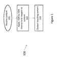
- Fig. 1 is a diagram depicting an exemplary method 100 for applying an HDR to HDR inverse tone mapper to an image or video content in accordance with present principles.
- Method 100 may be performed in any work flow.
- method 100 may be performed in a post-production studio to aid in the re-grading process or to produce a secondary grade with a higher peak luminance.
- method 100 may be utilized in connection with an HDR consumer display or may be integrated into a set-top box.
- the method 100 includes block 101 for receiving image or video content.
- the content may be decoded image or video content.
- the content may be raw image or video data content.
- the content may include a picture which may be video images or pictures, e.g., for HDR video.
- Block 101 may receive information regarding properties of a picture, including linear light RGB information.
- the content may be captured using tri-chromatic cameras into RGB color values composed of three components (Red, Green and Blue).
- the RGB color values depend on the tri-chromatic characteristics (color primaries) of the sensor.
- the content may include image side information such as color primaries of the sensor, maximum and minimum luminance peak of the captured scene.
- the content may have been previously decoded in accordance with any known standard, such as the High Efficiency Video Coding (HEVC) standard organized by the International Telecommunication (ITU) and the organization Moving Picture Experts Group (MPEG), or in accordance with the H.264 or MPEG-4 Part 10, Advanced Video Coding (MPEG-4 AVC) organized by the International Organization for Standardization/International Electrotechnical Commission (ISO/IEC) Moving Picture Experts Group-4 (MPEG-4).
- HEVC High Efficiency Video Coding
- ITU International Telecommunication
- MPEG-4 AVC Advanced Video Coding
- Block 101 may then pass control to block 102, including providing any information regarding the received content.
- Block 102 may apply a HDR to HDR inverse tone mapper to the content received from block 101.
- the HDR to HDR inverse tone mapper may be determined in accordance with present principles.
- the HDR to HDR inverse tone mapper converts a dynamic range of the content to expand to a dynamic range of the display.
- An aspect of present principles is directed to the application of the HDR to HDR inverse tone mapper.
- the HDR to HDR inverse tone mapper provides the ability to expand a range of luminance values by a very large amount.
- the application of the HDR to HDR inverse tone mapper results in a limited the amount of range expansion.
- the intended output device will preferably possess a high peak luminance, higher than the content received. This means that a comparatively gentle expansion in luminance range will suffice.
- the HDR to HDR inverse tone mapping operator may be global in nature, leaving many pixel values unchanged.
- the HDR to HDR inverse tone mapping operator may apply a small amount of expansion only to the lightest pixels. There may be the following advantages based on this process:
- An aspect of present principles is directed to an HDR to HDR inverse tone mapper includes one or more of the following:
- Block 103 may output the resulting content.
- Fig. 2 is a diagram depicting an exemplary method 200 for applying a HDR to HDR inverse tone mapper in accordance with present principles.
- Method 200 includes a block 201 for receiving metadata, including metadata relating to an HDR to HDR inverse tone mapper.
- the metadata may include inverse tone mapping curve parameters.
- Block 201 may then pass control to block 202.
- Block 202 may determine the HDR to HDR inverse tone mapping curve parameters.
- the parameters may include peak luminance of a target display I o max (see, e.g., Equation Nos. 3, 6, 7, 8, 13), peak luminance of content I max (see, e.g., Equation Nos. 3, 6, 7, 8, 13), parameter ⁇ , which is used to calculate the threshold ⁇ (see, e.g., Equation No. 9), parameter n , which determines the percentage of pixels to be subjected to non-linear compression (see, e.g., Equation Nos.
- parameter ⁇ which determines the maximum percentage of the pixels that can be expanded into a part of the dynamic range by the inverse tone mapper (see, e.g., Equation No. 13), and parameter ⁇ that is used in the leaky integration of the threshold for video content (see, e.g., Equation No. 14).
- the parameters may be utilized for determining a content dependent threshold in accordance with the principles described in connection with Equation No. 9, and Equation Nos. 10-14.
- Block 202 may also determine parameters a,c,d. The parameters may be determined based on criteria that enforce the inverse tone mapping curve to be a C1 function in accordance with Equation Nos. 3-8.
- Block 203 may receive content.
- the content may be raw image or video content.
- the content may be received via an encoded bit-stream and block 203 may decode the bit stream.
- the content may have been previously decoded.
- block 203 may receive content in accordance with principles outlined in connection with block 101 of Fig. 1 .
- Block 203 may pass control to block 204.
- Block 204 may obtain luminance channel information of the content from block 203.
- block 204 may apply a preliminary color transform to obtain luminance channel information.
- block 204 may determine luminance channel information in accordance with principles described in connection with Equation No. 1.
- block 204 may be optional and luminance information may be directly received from block 203.
- Block 205 may apply to the content from block 204 (or block 203) an HDR to HDR inverse tone mapper or HDR to HDR inverse tone mapping operator in accordance with present principles.
- block 205 may determine the inverse tone mapper curve based on the parameters received block 202.
- block 205 may selected a predetermined or stored inverse tone mapper based the parameters received from block 202.
- block 205 may apply and/or determine the HDR to HDR inverse tone mapper in accordance with principles described in connection with block 102 of Fig. 1 . In one example, block 205 may apply the HDR to HDR inverse tone mapper to determine an output I o . Block 205 may then pass control to block 206.
- Block 206 may perform color correction on the output of block 205.
- block 206 may perform color correction by scaling the RGB values based on a scale change in the luminance channel in accordance with Equation Nos. 15-a to 16-c.
- block 206 may be optional, and control may pass directly from block 205 to block 207.
- Block 206 may output color corrected content to block 207.
- Block 207 may output content processed by the HDR to HDR inverse tone mapper of block 205.
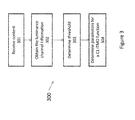
- Fig. 3 is a diagram depicting an exemplary method 300 for determining parameters for an HDR to HDR inverse tone mapper in accordance with present principles.
- the parameters may include parameters for the knee point ⁇ f (which may be determined in accordance with principles described in connection with Equation No. 13), and the curve parameters a,c,d (which may be determined in accordance with principles described in connection with Equation Nos. 6-8).
- Block 301 may receive content, which may include in whole or in part an image or a frame of a video.
- Block 301 may receive content in accordance with principles outlined in connection with block 101 of Fig. 1 or block 201 of Fig. 2 .
- Block 302 may determine luminance channel information (e.g., through a preliminary color transform). In one example, block 302 may determine luminance channel information in accordance with principles described in connection with Equation No. 1. Alternatively, block 302 may be optional and luminance channel information may be directly received from block 301.
- Block 303 may determine a threshold of the HDR to HDR inverse tone mapper.
- block 303 may determine a threshold that defines the knee point in the inverse tone mapping curve (which may be determined in accordance with principles described in connection with Equation Nos. 2-8).
- Block 303 may determine the maximum value on input luminance for which the input HDR content is only linearly changed in the output.
- a content-dependent threshold may be determined based on a minimum luminance value, compared to which less than ⁇ priori -fixed percentage of the pixels have higher luminance values. The content dependent threshold may be determined in accordance with the examples previous described in connection with regard to setting threshold ⁇ .
- block 303 may determine the threshold based on a cumulative histogram of the content. Denoting the cumulative histogram for value I by c I , the following condition may be verified: 100 c I max - c ⁇ c I max ⁇ n , where n denotes the percentage of the pixels that are allowed to be expanded by the non-linear part of the inverse tone mapping curve. If the condition of Equation No. 17 is satisfied, the initial value of the 80% of the maximum luminance of the input content may be considered as the knee point. If not, the threshold may be obtained using Equation No. 13. This example may be formalized through Equation Nos. 10-13.
- the input luminance image is may be provided a threshold value based on the initial value of the 80% of the maximum luminance of the input, and the number of pixels that have values bigger than the threshold are counted as well as the total number of pixels. Equation Nos. 12, 13 are then used to determine the final knee point of the inverse tone mapping curve.
- Block 304 may determine parameters for a C1 inverse tone mapping operator function
- the C1 function has its first derivative defined and continuous everywhere in the open interval of the input of the derivative function domain.
- the inverse tone mapper function is continuous, its derivative is continuous, and the maximum input is mapped to the maximum luminance of the output display.
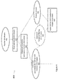
- Fig. 4 is a diagram depicting an exemplary method 400 for decoding content and applying an HDR to HDR inverse tone mapper in accordance with present principles.
- Method 400 may include a block 401.
- Block 401 may receive a bit-stream corresponding to image content, such as a video or image sequence.
- the received bit-stream may be encoded.
- Block 401 may pass control to block 402.
- Block 402 may parse and decode the bit-stream received from block 401.
- the block 402 may parse and decode the bit-stream using HEVC based decoding. Block 402 may then pass control to block 403.
- Block 403 may obtain luminance channel information.
- block 403 may obtain luminance channel information in accordance with principles described in connection with Equation No. 1.
- block 403 may be optional and luminance channel information may be directly received from block 402.
- Block 403 may then pass control to blocks 404 and 405.
- Block 404 may determine parameters for an HDR to HDR inverse tone mapper in accordance with present principles.
- the parameters may be any parameters discussed herewith in accordance with present principles.
- the parameters may be parsed and decoded from the bit-stream. In one example, the parameters are determined based off of syntax contained in the bit-stream (e.g., an SEI message).
- the parameters may be parameter threshold ⁇ f , and curve parameters a,b,c. These parameters can be transmitted through the bit-stream or can be determined at the decoder. For example, the parameters can be determined at the decoder based on the histogram of the luminance information. In one example, block 404 may determine parameters in accordance with method 300 of Fig. 3 .
- Block 405 may process a content that was parsed and decoded from the bit-stream. For example, block 405 may process a video or image sequence decoded from the bit-stream. In one example, block 504 may process a decoded Y'CbCr video signal. In one example, block 504 may convert an Y'CbCr video signal to a R'G'B' video signal. In another example, block 504 may process a R'G'B' video signal.
- Block 406 may perform optional temporal filtering of the inverse tone mapper curve.
- Block 406 may perform leaky integration to address potential flicker problems.
- the estimated thresholds for consecutive frames can be different.
- a correction of the estimated ⁇ f values for every new frame of the video may be determined.
- Leaky integration can be applied to the parameter ⁇ new t for frame t , which is estimated using ⁇ f t calculated as shown in the previous section, and the estimated leaky parameter for the previous frame, i.e., ⁇ new t - 1 . In one example, this may be performed in accordance with principles described in connection with Equation No. 14.
- the input of block 406 is the luminance channel information and the final threshold of the previous frame.
- the curve in block 406 corresponds to the inverse tone mapping curve.
- Block 406 is optional but strongly recommended to remove possible source of flicker in the output video.
- the output of the block 406 is the leaky determination of the threshold and the updated parameters of the inverse tone mapping curve using the principles described in connection with Equation Nos. 6-8 and 14.
- Block 407 may apply the HDR to HDR inverse tone mapper to the content from either block 405 or, if temporal filtering is applied, block 406.
- Block 407 applies the HDR to HDR inverse tone mapper in accordance with present principles.
- the HDR to HDR inverse tone mapper may be performed frame by frame using the parameters determined by block 404.
- block 407 may apply the HDR to HDR inverse tone mapper in accordance with principles described in connection with block 102 in Fig. 1 and block 205 in Fig. 2 .
- block 407 may create or may receive a Look Up Table (LUT) with tabulated values (e.g., based on Equation Nos. 13-14) and then applying the LUT to the content.
- LUT Look Up Table
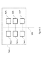
- Fig. 5 represents an exemplary architecture of an apparatus 500 which may be configured to implement methods described in relation with Fig. 1-4 and Equation Nos. 1-17.
- Fig. 5 represents an apparatus that may be configured to implement the methods according to present principles, including principles described in relation to Figs. 1-4 .
- Fig. 5 represents an apparatus that may be configured to implement the decoding method according to present principles, including principles described in relation to Fig. 4 .
- Apparatus 500 comprises following elements that are linked together by a data and address bus 501:
- the battery 506 is external to the apparatus.
- the word « register » used in the specification can correspond to area of small capacity (some bits) or to very large area (e.g. a whole program or large amount of received or decoded data).
- ROM 503 comprises at least a program and parameters. Algorithm of the methods according to the invention is stored in the ROM 503. When switched on, the CPU 502 uploads the program in the RAM and executes the corresponding instructions.
- RAM 504 comprises, in a register, the program executed by the CPU 502 and uploaded after switch on of the apparatus 500, input data in a register, intermediate data in different states of the method in a register, and other variables used for the execution of the method in a register.
- the implementations described herein may be implemented in, for example, a method or a process, an apparatus, a software program, a data stream, or a signal. Even if only discussed in the context of a single form of implementation (for example, discussed only as a method or an apparatus), the implementation of features discussed may also be implemented in other forms (for example a program).
- An apparatus may be implemented in, for example, appropriate hardware, software, and firmware.
- the methods may be implemented in, for example, an apparatus such as, for example, a processor, which refers to processing devices in general, including, for example, a computer, a microprocessor, an integrated circuit, or a programmable logic device. Processors also include communication devices, such as, for example, computers, cell phones, portable/personal digital assistants ("PDAs”), and other devices that facilitate communication of information between end-users.
- PDAs portable/personal digital assistants
- the image or picture I is obtained from a source.
- the source belongs to a set comprising:
- the decoded image Î is sent to a destination; specifically, the destination belongs to a set comprising:
- bitstream BF and/or F are sent to a destination.
- bitstream F and BF or both bitstreams F and BF are stored in a local or remote memory, e.g. a video memory (504) or a RAM (504), a hard disk (503).
- a storage interface (505) e.g. an interface with a mass storage, a flash memory, ROM, an optical disc or a magnetic support and/or transmitted over a communication interface (505), e.g. an interface to a point to point link, a communication bus, a point to multipoint link or a broadcast network.
- the bitstream BF and/or F is obtained from a source.
- the bitstream is read from a local memory, e.g. a video memory (504), a RAM (504), a ROM (503), a flash memory (503) or a hard disk (503).
- the bitstream is received from a storage interface (505), e.g. an interface with a mass storage, a RAM, a ROM, a flash memory, an optical disc or a magnetic support and/or received from a communication interface (505), e.g. an interface to a point to point link, a bus, a point to multipoint link or a broadcast network.
- apparatus 500 being configured to implement an encoding method in accordance with present principles, belongs to a set comprising:
- apparatus 500 being configured to implement a decoding method in accordance with present principles, belongs to a set comprising:
- Implementations of the various processes and features described herein may be embodied in a variety of different equipment or applications.
- Examples of such equipment include an encoder, a decoder, a post-processor processing output from a decoder, a preprocessor providing input to an encoder, a video coder, a video decoder, a video codec, a web server, a set-top box, a laptop, a personal computer, a cell phone, a PDA, and other communication devices.
- the equipment may be mobile and even installed in a mobile vehicle.
- the methods may be implemented by instructions being performed by a processor, and such instructions (and/or data values produced by an implementation) may be stored on a processor-readable medium such as, for example, an integrated circuit, a software carrier or other storage device such as, for example, a hard disk, a compact diskette (“CD"), an optical disc (such as, for example, a DVD, often referred to as a digital versatile disc or a digital video disc), a random access memory (“RAM”), or a read-only memory (“ROM”).
- the instructions may form an application program tangibly embodied on a processor-readable medium. Instructions may be, for example, in hardware, firmware, software, or a combination.
- a processor may be characterized, therefore, as, for example, both a device configured to carry out a process and a device that includes a processor-readable medium (such as a storage device) having instructions for carrying out a process. Further, a processor-readable medium may store, in addition to or in lieu of instructions, data values produced by an implementation.
- implementations may produce a variety of signals formatted to carry information that may be, for example, stored or transmitted.
- the information may include, for example, instructions for performing a method, or data produced by one of the described implementations.
- a signal may be formatted to carry as data the rules for writing or reading the syntax of a described example, or to carry as data the actual syntax-values written by a described example.
- Such a signal may be formatted, for example, as an electromagnetic wave (for example, using a radio frequency portion of spectrum) or as a baseband signal.
- the formatting may include, for example, encoding a data stream and modulating a carrier with the encoded data stream.
- the information that the signal carries may be, for example, analog or digital information.
- the signal may be transmitted over a variety of different wired or wireless links, as is known.
- the signal may be stored on a processor-readable medium.
- Various examples of the present invention may be implemented using hardware elements, software elements, or a combination of both. Some examples may be implemented, for example, using a computer-readable medium or article which may store an instruction or a set of instructions that, if executed by a machine, may cause the machine to perform a method and/or operations in accordance with the examples.
- a machine may include, for example, any suitable processing platform, computing platform, computing device, processing device, computing system, processing system, computer, processor, or the like, and may be implemented using any suitable combination of hardware and/or software.
- the computer-readable medium or article may include, for example, any suitable type of memory unit, memory device, memory article, memory medium, storage device, storage article, storage medium and/or storage unit.
- the instructions may include any suitable type of code, such as source code, compiled code, interpreted code, executable code, static code, dynamic code, encrypted code, and the like, implemented using any suitable high-level, low-level, object-oriented, visual, compiled and/or interpreted programming language.
- the implementations described herein may be implemented in, for example, a method or a process, an apparatus, a software program, a data stream, or a signal. Even if only discussed in the context of a single form of implementation (for example, discussed only as a method), the implementation of features discussed may also be implemented in other forms (for example, an apparatus or program).
- An apparatus and constituents included therein, for example, a processor, an encoder and a decoder may be implemented in, for example, appropriate hardware, software, and firmware.
- the methods may be implemented in, for example, an apparatus such as, for example, a processor, which refers to processing devices in general, including, for example, a computer, a microprocessor, an integrated circuit, or a programmable logic device. Processors also include communication devices, such as, for example, computers, cell phones, portable/personal digital assistants ("PDAs”), and other devices that facilitate communication of information between end-users.
- PDAs portable/personal digital assistants
- Determining the information may include one or more of, for example, estimating the information, calculating the information, predicting the information, or retrieving the information from memory.
- Accessing the information may include one or more of, for example, receiving the information, retrieving the information (for example, from memory), storing the information, processing the information, transmitting the information, moving the information, copying the information, erasing the information, calculating the information, determining the information, predicting the information, or estimating the information.
- Receiving is, as with “accessing”, intended to be a broad term.
- Receiving the information may include one or more of, for example, accessing the information, or retrieving the information (for example, from memory).
- “receiving” is typically involved, in one way or another, during operations such as, for example, storing the information, processing the information, transmitting the information, moving the information, copying the information, erasing the information, calculating the information, determining the information, predicting the information, or estimating the information.
- the parameterized transfer function is signaled in the picture encoded or decoded according to the invention, or in a stream including the picture.
- an information representative of the parameterize transfer function is signaled in the picture or in the stream including the picture. This information is used by a decoding method or decoder to identify the parameterized transfer function that is applied according to the invention.
- this information includes an identifier that is known on encoding and decoding side.
- this information includes parameters used as a basis for parameterized transfer functions.
- this information comprises an indicator of the parameters in the picture or in a bit-stream including the picture, based on a set of defined values.
- this information comprises an indication based on whether the parameters are signaled explicitly or whether the parameters are signaled implicitly based on a set of defined values.
- this information is included in at least one syntax element included in at least one of a Picture Parameter Set (PPS), a Sequence Parameter Set (SPS), a Supplemental Enhancement Information (SEI) message, a Video Usability Information (VUI), Consumer Electronics Association (CEA) message, and a header.
- PPS Picture Parameter Set
- SPS Sequence Parameter Set
- SEI Supplemental Enhancement Information
- VUI Video Usability Information
- CEA Consumer Electronics Association
Landscapes
- Engineering & Computer Science (AREA)
- Multimedia (AREA)
- Signal Processing (AREA)
- Physics & Mathematics (AREA)
- General Physics & Mathematics (AREA)
- Theoretical Computer Science (AREA)
- Image Processing (AREA)
- Picture Signal Circuits (AREA)
- Two-Way Televisions, Distribution Of Moving Picture Or The Like (AREA)
- Facsimile Image Signal Circuits (AREA)
- Compression Or Coding Systems Of Tv Signals (AREA)
Abstract
The present invention proposes to provide methods, apparatus and systems for inverse tone mapping of a high dynamic range image. The method may include the operations of obtaining a luminance component of the high dynamic range image. The method may further include determining an HDR to HDR inverse tone mapper operator. The method may further include determining a tone expanded image by applying the HDR to HDR inverse tone mapper to the luminance component of the high dynamic range image. The method may further include wherein the HDR to HDR inverse tone mapper curve comprises a linear part for dark and mid-tone levels, and an expanding non-linear part for highlights. The system or apparatus may be configured to perform the operations of the method.
Description
- The present disclosure relates to image and video processing. In particular, the present disclosure relates to conversion of image or video data utilizing a High Dynamic Range ("HDR") inverse tone mapping operator.
- Light in nature covers an enormous range of luminance levels, from starlight to bright sunlight. Yet traditional imaging technologies, both digital and analog, offer diminished experience because they cannot parallel the wide range of luminance and contrast that is visible to human eyes. In response, HDR technologies are being developed to allow for the display of an extended range of color, luminance and contrast. HDR technologies focus on capturing, processing and displaying content of a wider dynamic range. Although there are HDR displays, and although cameras capable of capturing an increased dynamic range are being developed, there is still very limited HDR content available.
- To prepare conventional content for HDR displays, reverse or inverse tone mapping operators (ITMO) can be employed in connection with algorithms to process the luminance information in an image with the aim of recovering or recreating the appearance of the image's original scene. Typically, ITMOs take a conventional image as input (e.g., a standard dynamic range ("SDR") image), expand the luminance range of the image in a non-linear manner, and process highlights or bright regions locally to enhance the HDR appearance of the resulting image.
- Existing ITMO solutions focus on perceptually reproducing the appearance of an original scene and rely on strict assumptions about the image's content. Existing ITMO solutions are rarely created with video in mind and they do not provide sufficient controls to be used within a color grading context.
- Existing ITMO solutions are problematic because they increase the range of luminance values by a very large amount. The difference between light levels observed in the real world and the input (normally around 100 nits) is very significant, forcing the design of appropriate ITMOs to make trade-offs between visual quality and computational complexity. For example, existing ITMOs enlarge a very low range of legacy non-HDR content (e.g., 100 nits content), into a full luminance channel information (e.g., maximum 4000 nits content).
- In some cases, however, the ITMO is required to enlarge the range by a significantly smaller factor, e.g., from a maximum of 1500 nits to 4000 nits (e.g., for range expansion between different HDR displays). This fits with the currently observed trend that display devices have a dynamic range that is increasingly less uniform. With a large variety of displays with different capabilities deployed, content providers will not be able to provide separate grades for each different display.
- An aspect of present principles is directed to re-mastering SDR (standard dynamic range) video content to HDR content, e.g., in the context of a color grading workflow. To achieve a gentle dynamic range expansion, there is a need for a solution that correctly reproduces the intent of the provider, including maintaining a high peak luminance even if the peak luminance is higher than the peak luminance of the received content.
- The present invention proposes to provide methods, apparatus and systems for inverse tone mapping of an HDR image. The method may include the operations of obtaining a luminance component of the HDR image. The method may further include determining an inverse tone mapper curve. The method may further include determining a tone expanded image by applying the HDR to HDR inverse tone mapper curve to the luminance component of the HDR image. The method may further include wherein the HDR to HDR inverse tone mapper curve comprises a linear part for dark and mid-tone levels, and an expanding non-linear part for highlights. The systems or apparatus may be configured to perform the operations of the method.
- The method, apparatus or system may include wherein the HDR to HDR inverse tone mapper includes a threshold for determining when the luminance is changed linearly and when the luminance is decompressed.
- The method, apparatus or system may include wherein the threshold is determined based on the following:

- The method, apparatus or system may include operations for determining the threshold based on content.
- The method, apparatus or system may include criteria to enforce continuity and smoothness of the HDR to HDR inverse tone mapper curve.
- The method, apparatus or system may include wherein the HDR image is part of an HDR video, and wherein the application of the HDR to HDR inverse tone mapper curve includes applying information from prior video frames to achieve temporal stability.
- The method, apparatus or system may include wherein the information from prior video frames is applied using leaky integration based on the threshold.
- The method, apparatus or system may include signaling information representative of the HDR to HDR inverse tone mapper curve. The signaling may be performed using at least one syntax element included in at least one of a Picture Parameter Set (PPS), a Sequence Parameter Set (SPS), a Supplemental Enhancement Information (SEI) message, a Video Usability Information (VUI), Consumer Electronics Association (CEA) message, and a header.
- In another example, the present principles further provide for methods, apparatus or system for tone mapping an HDR image. The method may include obtaining a luminance component of the HDR image; determining an HDR to HDR inverse tone mapper curve; determining a tone decompressed image by applying the HDR to HDR inverse tone mapper curve to the luminance component of the high dynamic range image; wherein the HDR to HDR inverse tone mapper curve is multi-segmented, and wherein the multi-segmented curve includes at least a segment that is not linear and at least a segment that is linear. The system or apparatus may be configured to perform the operations of the method.
- The method, apparatus or system may include wherein the linear segment is directed to at least one selected from a group of darks, mid-tones, and highlights, and wherein the non-linear segment is directed to at least one selected from a group of darks, mid-tones, and highlights.
- In another example, the present principles further provide for methods, apparatus or system for tone mapping an HDR image. The method may include obtaining a luminance component of the HDR image; determining an HDR to HDR inverse tone mapper curve; determining a tone decompressed image by applying the HDR to HDR inverse tone mapper curve to the luminance component of the HDR image; wherein the parameters of the HDR to HDR inverse tone mapper curve are linearly or non-linearly modulated as a function of the threshold to satisfy predefined conditions.
- The features and advantages of the present invention may be apparent from the detailed description below when taken in conjunction with the Figures described below:
-
Figure 1 is a diagram depicting an exemplary method for applying an HDR to HDR inverse tone mapper in accordance with present principles. -
Figure 2 is a diagram depicting an exemplary method for applying an HDR to HDR inverse tone mapper in accordance with present principles. -
Figure 3 is a diagram depicting an exemplary method for determining parameters for an HDR to HDR inverse tone mapper in accordance with present principles. -
Figure 4 is a diagram depicting an exemplary method for decoding content and applying an HDR to HDR inverse tone mapper in accordance with present principles. -
Figure 5 is a diagram depicting an exemplary apparatus in accordance with present principles. -
Figure 6 is a diagram depicting an exemplary plot in accordance with present principles. -
Figure 7 is a diagram depicting an exemplary plot in accordance with present principles. -
Figure 8 is a diagram depicting an exemplary plot in accordance with present principles. - The present principles are directed to methods, apparatus and systems for HDR to HDR inverse tone mapping and/or an HDR to HDR inverse tone mapper.
- An aspect of present principles may be implemented in hardware such as Field Programmable Gate Arrays (FPGAs) and Systems on Chip (SoCs), although it could be implemented without restriction in other types of hardware such as general purpose processing units and graphics processing units. The minimal processing capabilities of FPGAs and SoCs, combined with the increasing need for processing due to higher frame resolutions (such as UHD or 4K content) as well as higher frame rates, may limit the processing that can be implemented on such devices. The present principles address the problem of inverse tone reproduction in a manner consistent with such potential device limitations.
- An aspect of present principles is directed to tone reproduction and inverse tone reproduction that may be used as part of an encoding/decoding scheme. For example, HDR video may be processed by a tone reproduction operator, serving the role of an opto-electrical transfer function (OETF). The resulting video can then be passed to the encoder, including but not limited to AVC or HEVC. The encoded bitstream may then be transmitted to the recipient, where the corresponding decoder is applied. The inverse OETF (often referred to as the electro-optical transfer function (EOTF)) may then be applied to the decoded content, resulting in the reconstruction of the HDR video.
- An aspect of present principles addresses the problem of diminishing quality of a dynamic range of HDR content when content is converted to a target display. An aspect of present principles relates to reproducing an HDR sensation despite the expansion required to fit content into a target display range.
- An aspect of present principles relates to methods, apparatus and systems for maintaining quality of displayed HDR content similar to the quality at a source, while expanding the HDR content only for very high ranges of information. Even though input content may have a lower dynamic range than the range of output displays, the sensation of viewing HDR content may still exist. This may also enable maintaining a director's intent. For example, content graded on a 4000 nit reference display and compressed into the range of 1000 nits would have a high quality reproduction for display on 4000 or 1500 nit consumer displays.
- An aspect of present principles is directed to an HDR to HDR inverse tone mapping operator that may be utilized in various applications. For example, the HDR to HDR inverse tone mapping operator may be utilized in a post-production studio, to aid in the re-grading process or to produce a secondary grade with a higher peak luminance. Alternatively, on the consumer side, the HDR to HDR inverse tone mapping operator could be incorporated into an HDR consumer display or could be integrated into a set-top box.
- An aspect of present principles relates to a HDR to HDR inverse tone mapper's determination that either changes dark and mid-tone levels linearly or does not change the mid-tone levels. This may preserve the intent of a photographer, an artist or a producer. The HDR to HDR inverse tone mapper may be applied to a luminance channel, and may correct chromatic information secondarily.
- An aspect of present principles relates to determining a threshold τ for a luminance channel. After determining threshold τ, input values for the luminance channel are changed linearly when the input values are lower than (or lower than equal to) the threshold τ. The input values lower than the threshold hold value may be changed linearly based on of a scaling factor s. The scaling factor s may also be set to s = 1, thereby keeping the input values unchanged for a corresponding luminance value range. An aspect of present principles relates to expanding very high luminance values (e.g., luminance values larger than or larger than and equal to threshold τ) using a variation of an inverse tone mapper. An aspect of present principles is directed to an HDR to HDR inverse tone mapper that can be represented by a continuous curve, with a smooth profile transition around the threshold value τ.
- An aspect of present principles relates to a preliminary color transformation that determines the luminance channel information based on RBG values. An aspect of present principles further relates to determining the design for an inverse tone mapper by introducing the conditions on the inverse tone mapping curve. An aspect of present principles relates to determining the threshold τ from the content itself.
- An aspect of present principles relates to determining luminance information for each pixel based on a transformation of content (e.g., decoded content). In one example, the content may be formatted for a standard RGB color space. In one example, if the content is given in the sRGB color space, the calculation of a luminance value for a pixel I is given by:

- Luminance values can be derived from other RGB color spaces in a similar manner, however the constants in Equation No. 1 will then be different. The constants of Equation No. 1 may depend on the definition of the RGB color space. Examples of RGB color spaces include ISO RGB, Extended ISO RGB, scRGB, Adobe RGB 98, Adobe Wide Gamut RGB, Apple RGB, ROMM RGB, ProPhoto RGB, CIE (1931) RGB, as well as RGB spaces defined in standards ITU-R Rec. BT 709, ITU-R Rec. BT 2020, ITU-R Rec. BT 470, SMPTE RP 145, and SMPTE 170M.
- Alternatively, the luminance channel of any appropriate color space, such as Yuv, Yu'v', YCbCr, YPbPr, Y'DbDr, Y'CC, CIE Yxy, CIE Lab, CIE Luv, CIE LCh, IPT, Y'I'Q', EBU Y'U'V' may be utilized. The image may be transformed into such a color space. Further processing may be then applied to the luminance channel of the transformed image. A further color space transform may then convert the image to a destination color space (which may be an RGB color space).
- An aspect of present principles is directed to an HDR to HDR inverse tone mapping algorithm that expands luminance values based on a determination that the luminance values are greater than (or greater than or equal to) a fixed threshold. In one example, the threshold may be determined using a slider in a GUI. In another example, the threshold may be provided (along with input content) as metadata. In another example, the threshold can be automatically estimated.
- In one example, a C1 inverse tone mapping function is designed for the full range of the input luminance. As used herein, a "C1" function is defined as a function with its first derivative being defined and continuous everywhere in the open interval of the input of the derivative function domain. In other words, the smoothness criterion is not defined at I = 0 and I = Imax.
- In one example, Imax may be the maximum luminance value of input content and


- In one example, an inverse tone mapper function may be represented as


- An aspect of present principles is directed to an HDR to HDR inverse tone mapper
 . In one example, the HDR to HDR inverse tone mapper may be defined as:

- In Equation No. 2, the value of b may be preset to 1. The three parameters a, c, d need to be set to satisfy the following three conditions to obtain an C1 inverse tone mapper

- i. The maximum input Imax should map to the maximum output


- ii. At I = τ, the inverse tone mapper needs to be continuous, therefore

- iii. Also, at I = τ, the gradient of the inverse tone mapper needs to be continuous, therefore,

- Solving the system of Equation Nos. 3-5 for the three unknowns a, c, d, results into the following:


- In one example, the methodology described above in connection with Equation Nos. 2 may be implemented through a Look-Up-Table with the sampled input values and output values for real-time inverse tone mapping.
-
Fig. 6 illustrates a plot of I versus
Fig. 6 is determined for = 1200, s = 1, Imax = 1500,
line 601 inFig. 6 . The plot shows the overall behavior of the inverse tone mapper function
-
Fig. 7 illustrates a plot for log(I) versus
line 701 inFig. 7 . This curve shows the inverse tone mapper in logarithmic space. - The plots shown in
Figs. 6 and7 illustrate the behavior of the inverse tone mapper, i.e., linear in dark and mid-tone levels, and expanding in the highlights. - The method of Equations Nos. 2 to 8 describes an inverse tone mapping approach with a linear segment for the dark parts and the mid-tones of an image. The lightest parts (for instance the highlights) of the image are expanded with a non-linear function. A cross-over point determines the maximum value in the input which is passed through the linear part of the function, and the smallest value of the input which is passed through the non-linear part of the function.
- An aspect of present principles is directed to a second cross-over point (or a threshold) that separates the darkest part of the image (the blacks) from the remainder of the image. The blacks can be processed in a non-linear manner, such as when the black-level of the target display device is higher or lower than the black level of the content or the black level of the grading monitor that was used to create the content.
- An aspect of present principles is directed to processing of a curve representing an HDR to HDR inverse tone mapper based on a cross-over point or threshold. In one example, the curve may be modulated based on the cross-over point. The modulation can be linear or non-linear. In one example, the modulation may result in convergence of the parameters of Equation No. 2 to defined values. In one example, the values of parameters a and d may converge to -1, and the value of parameter c converge to 0, when the cross-over point converges to 0. When the cross-over point converges to 0,


- An aspect of present principles is directed to determining, based on a threshold τ, a maximum value for an input Ii for which input HDR content is only processed resulting in an output


- For example, when Imax = 1500 nits, the threshold τ can be initialized to 1200. This choice of η and n has been experimentally shown to result in subjectively pleasant output images.
- In one example, a content-dependent threshold τ is determined based on minimum luminance value. The minimum luminance value is based on a determination that less than n % of the pixels have higher luminance values. In other words, the goal is to find the smallest luminance value that has less than n % of the total pixel numbers lie on its right hand side on the histogram.
- In one example, the threshold n (which corresponds to the percentage of the pixels that are going to be expanded) is set to 2%. The threshold n determines the number of pixels that are being changed. However, in other examples, the value for the threshold n may be set to any other value. In one example, the value for the threshold n may depend on the type of content or application (e.g., a display device or a content capturing device).
- In one example, the content dependent threshold τ (i.e., the knee point in the inverse tone mapping curve) may be determined based on a cumulative histogram of the content. The frequency of input luminance I may be denoted by hI. The value of hI can be determined by calculating a histogram of the input luminance image with any number of bins. The cumulative histogram for value I is denoted by cI and can be found through the following:

- In one example, the final threshold may be set equal to the initial value τf = τ if:

- The condition in Equation No. 11 is satisfied when there are less than n % of pixels that fall between τ and Imax . This allows linearly changing only more than (100 - n)% of the pixels. If the condition in Equation No. 11 is not satisfied, the breaking point (i.e., the knee point in the tone mapping curve) is pushed back to increase the range in which the input is expanded.
- In one example, the value of ρ is denoted as follows:

- Based on Equation No. 12, the value of a threshold τ may be determined as follows (consisting of linearly reducing τf):

- In Equation No. 13, the parameter α denotes the maximum percentage of the pixels that can be expanded to only a small part of a dynamic range by the inverse tone mapper

Fig. 8 , for which α = 12.5.
As a consequence, for any choice of α, the value for the final threshold τf for ρ > α is set to 0 (this determination may be performed on an image level, block level, etc.). The value for the final threshold τf is beneficial because more than α % of the pixels are touched if any threshold larger than 0 is chosen. In another example, a threshold τ may be determined based on the determination of the values for cImax and cImax - cτ . In one example, cImax is set to the number of pixels in the image. In one example, cImax - cτ indicates a number of pixels that have intensities higher than the threshold τ. A fast estimation of cImax - cτ (and consequently p) is obtained by counting the number of pixel intensities that are higher than the threshold τ. The final threshold τf may then be determined based on Equation No. 13. - In the examples above, the final threshold τf depends on image content and is smaller than the initial threshold τ. In one example, when utilized in a decoder, the final threshold τf prevents the expansion of too many pixels into the range of

- For video content, thresholds for consecutive video frames can have different values. This may result in undesirable, noticeable variations in the intensity of consecutive video frames ("flicker").
- An aspect of present principles addresses the problem of flicker by correcting of a final threshold τf values for various video frames.
- In one example, leaky integration can be applied to obtain a parameter


- The iterative nature of Equation No. 14 implies that for every video frame, the prior determinations are considered. The user parameter β ∈ [0 1] controls the smoothness of τnew among the video frames. In one example this threshold is received along with the encoded content by a decoder.
- An aspect of present principles is directed to deriving luminance values from RGB pixel values according to Equation No. 1. To reconstruct an inverse tone mapped color image, a simple pixel-wise approach may be utilized. The pixel-wise approach scales RGB values according to a scale change in a luminance channel, as follows:


- An aspect of present principles is directed to an HDR to HDR inverse tone mapper or mapping operator that is incorporated into a consumer electronics device such as a set-top box, a television, a monitor, a laptop, a phone, a tablet, a smartphone display, etc. An HDR to HDR inverse tone mapping process or information may be supplied as meta-data to the device in order to determine the visual appearance of the device's output. The HDR to HDR inverse tone mapping information may be provided as follows:
- The peak luminance of the target display

- The peak luminance of the content Imax may be provided as meta-data. The peak luminance value may be provided as a single value per video frame, per shot, or per program (e.g., television episode, movie, commercial). In another example, the value of Imax may be interpreted as the peak luminance of the utilized display device (for instance in a post-production house), or the peak luminance of a live camera used in a broadcast scenario (see Equation Nos. 3, 6, 7, 8, 13). In another example, Imax is the peak luminance of the compressed HDR content that is broadcast to an end-user.
- The parameter η, which is used to calculate the threshold τ, may also be provided as meta-data. In one example, the threshold τ, which determines a cross-over between the linear and non-linear parts of the inverse tone mapping curve, may be sent instead (see Equation No. 9). The cross-over point may also be known as the threshold. The parameter n determines the percentage of pixels to be subjected to non-linear expansion (see Equation Nos. 10, 13).
- The parameter α may also be provided as meta-data (see Equation No. 13).
- The parameter β that is used in the leaky integration of the threshold for video content may also be included in the meta-data (see Equation No. 14).
- By giving a producer of the content (e.g., a director of photography, colorist, studio, etc.) control over each of the parameters η (or τ), n, α and β, the producer's intent can advantageously be better reproduced on a wide variety of displays.
- An algorithm in accordance with present principles (e.g., Equation Nos. 1-16) was tested on HDR images. The experimental results demonstrated that the inverse tone mapper


- When an HDR video frame is processed in accordance with a present principles, a significant portion of all pixels (typically all the black and mid-tones), remained unchanged, and only the highest pixel values expanded. In contrast, linear scaling would have changed all pixel values by the same amount, which all other known inverse tone mapping operators perform.
- An advantage of present principles is that the amount of range expansion is strictly limited. The intended output device will possess a high peak luminance, higher than the content received. This means that a comparatively gentle expansion in luminance range will suffice. As such, it is possible to design an inverse tone mapping operator that is global in nature, and in fact leaves many pixel values unchanged. The small amount of expansion is applied only to the lightest pixels. The advantage of this approach is as follows:
- Very low computational complexity
- Most pixels are reproduced as intended
- A much smaller number of pixels receives some expansion in value, such that contrast increase (and thereby loss of the intended contrast) is minimized.
- The examples described above may be implemented within the figures described below.
Fig. 1 is a diagram depicting anexemplary method 100 for applying an HDR to HDR inverse tone mapper to an image or video content in accordance with present principles. -
Method 100 may be performed in any work flow. For example,method 100 may be performed in a post-production studio to aid in the re-grading process or to produce a secondary grade with a higher peak luminance. Alternatively,method 100 may be utilized in connection with an HDR consumer display or may be integrated into a set-top box. - In one example, the
method 100 includesblock 101 for receiving image or video content. The content may be decoded image or video content. Alternatively, the content may be raw image or video data content. The content may include a picture which may be video images or pictures, e.g., for HDR video.Block 101 may receive information regarding properties of a picture, including linear light RGB information. The content may be captured using tri-chromatic cameras into RGB color values composed of three components (Red, Green and Blue). The RGB color values depend on the tri-chromatic characteristics (color primaries) of the sensor. The content may include image side information such as color primaries of the sensor, maximum and minimum luminance peak of the captured scene. The content may have been previously decoded in accordance with any known standard, such as the High Efficiency Video Coding (HEVC) standard organized by the International Telecommunication (ITU) and the organization Moving Picture Experts Group (MPEG), or in accordance with the H.264 or MPEG-4Part 10, Advanced Video Coding (MPEG-4 AVC) organized by the International Organization for Standardization/International Electrotechnical Commission (ISO/IEC) Moving Picture Experts Group-4 (MPEG-4).Block 101 may then pass control to block 102, including providing any information regarding the received content. -
Block 102 may apply a HDR to HDR inverse tone mapper to the content received fromblock 101. The HDR to HDR inverse tone mapper may be determined in accordance with present principles. The HDR to HDR inverse tone mapper converts a dynamic range of the content to expand to a dynamic range of the display. - An aspect of present principles is directed to the application of the HDR to HDR inverse tone mapper. The HDR to HDR inverse tone mapper provides the ability to expand a range of luminance values by a very large amount. The application of the HDR to HDR inverse tone mapper results in a limited the amount of range expansion. The intended output device will preferably possess a high peak luminance, higher than the content received. This means that a comparatively gentle expansion in luminance range will suffice. The HDR to HDR inverse tone mapping operator may be global in nature, leaving many pixel values unchanged. The HDR to HDR inverse tone mapping operator may apply a small amount of expansion only to the lightest pixels. There may be the following advantages based on this process:
- Very low computational complexity;
- Most pixels are reproduced as intended;
- A much smaller number of pixels receives some expansion in value, such that contrast increase (and thereby the intended contrast of the content) is minimized.
- An aspect of present principles is directed to an HDR to HDR inverse tone mapper includes one or more of the following:
- a linear part for dark and mid-tone levels and a nonlinear expanding part for highlights (see, e.g., Equation No. 2);
- a curve design of the representation of the HDR to HDR inverse tone mapping curve resulting in a C1 function. (see, e.g., Equation Nos. 3-8);
- a content-based knee point/threshold determination (see, e.g., Equation Nos. 10-14) In one example, the HDR to HDR inverse tone mapper may be represented by a linear curve with a small expansion range, where the design of the curve matches smoothness criteria and a curve threshold is determined based on content.
-
Block 103 may output the resulting content. -
Fig. 2 is a diagram depicting anexemplary method 200 for applying a HDR to HDR inverse tone mapper in accordance with present principles. -
Method 200 includes ablock 201 for receiving metadata, including metadata relating to an HDR to HDR inverse tone mapper. The metadata may include inverse tone mapping curve parameters.Block 201 may then pass control to block 202. - Block 202 may determine the HDR to HDR inverse tone mapping curve parameters. The parameters may include peak luminance of a target display

-
Block 203 may receive content. In one example, the content may be raw image or video content. In another example, the content may be received via an encoded bit-stream and block 203 may decode the bit stream. In another example, the content may have been previously decoded. In one example, block 203 may receive content in accordance with principles outlined in connection withblock 101 ofFig. 1 .Block 203 may pass control to block 204. -
Block 204 may obtain luminance channel information of the content fromblock 203. In one example, block 204 may apply a preliminary color transform to obtain luminance channel information. In one example, block 204 may determine luminance channel information in accordance with principles described in connection with Equation No. 1. In another example, block 204 may be optional and luminance information may be directly received fromblock 203. -
Block 205 may apply to the content from block 204 (or block 203) an HDR to HDR inverse tone mapper or HDR to HDR inverse tone mapping operator in accordance with present principles. In one example, block 205 may determine the inverse tone mapper curve based on the parameters received block 202. In another example, block 205 may selected a predetermined or stored inverse tone mapper based the parameters received from block 202. - In one example, block 205 may apply and/or determine the HDR to HDR inverse tone mapper in accordance with principles described in connection with
block 102 ofFig. 1 . In one example, block 205 may apply the HDR to HDR inverse tone mapper to determine an output Io. Block 205 may then pass control to block 206. -
Block 206 may perform color correction on the output ofblock 205. For example, block 206 may perform color correction by scaling the RGB values based on a scale change in the luminance channel in accordance with Equation Nos. 15-a to 16-c. In one example, block 206 may be optional, and control may pass directly fromblock 205 to block 207.Block 206 may output color corrected content to block 207. -
Block 207 may output content processed by the HDR to HDR inverse tone mapper ofblock 205. -
Fig. 3 is a diagram depicting anexemplary method 300 for determining parameters for an HDR to HDR inverse tone mapper in accordance with present principles. The parameters may include parameters for the knee point τf (which may be determined in accordance with principles described in connection with Equation No. 13), and the curve parameters a,c,d (which may be determined in accordance with principles described in connection with Equation Nos. 6-8). -
Block 301 may receive content, which may include in whole or in part an image or a frame of a video.Block 301 may receive content in accordance with principles outlined in connection withblock 101 ofFig. 1 or block 201 ofFig. 2 . -
Block 302 may determine luminance channel information (e.g., through a preliminary color transform). In one example, block 302 may determine luminance channel information in accordance with principles described in connection with Equation No. 1. Alternatively, block 302 may be optional and luminance channel information may be directly received fromblock 301. -
Block 303 may determine a threshold of the HDR to HDR inverse tone mapper. In one example, block 303 may determine a threshold that defines the knee point in the inverse tone mapping curve (which may be determined in accordance with principles described in connection with Equation Nos. 2-8).Block 303 may determine the maximum value on input luminance for which the input HDR content is only linearly changed in the output. A content-dependent threshold may be determined based on a minimum luminance value, compared to which less than α priori-fixed percentage of the pixels have higher luminance values. The content dependent threshold may be determined in accordance with the examples previous described in connection with regard to setting threshold τ. - In one example, block 303 may determine the threshold based on a cumulative histogram of the content. Denoting the cumulative histogram for value I by cI, the following condition may be verified:

-
Block 304 may determine parameters for a C1 inverse tone mapping operator function The C1 function has its first derivative defined and continuous everywhere in the open interval of the input of the derivative function domain. In particular, the inverse tone mapper function is continuous, its derivative is continuous, and the maximum input is mapped to the maximum luminance of the output display. These criteria are formalized in Equation Nos. 3-5 and the consequently determined parameters of the curve are obtained in Equation Nos. 6-8.Block 304 may output the parameter for threshold τf, and the curve parameters a,b,c. -
Fig. 4 is a diagram depicting anexemplary method 400 for decoding content and applying an HDR to HDR inverse tone mapper in accordance with present principles.Method 400 may include ablock 401. -
Block 401 may receive a bit-stream corresponding to image content, such as a video or image sequence. The received bit-stream may be encoded.Block 401 may pass control to block 402. -
Block 402 may parse and decode the bit-stream received fromblock 401. In one example, theblock 402 may parse and decode the bit-stream using HEVC based decoding.Block 402 may then pass control to block 403. -
Block 403 may obtain luminance channel information. In one example, block 403 may obtain luminance channel information in accordance with principles described in connection with Equation No. 1. Alternatively, block 403 may be optional and luminance channel information may be directly received fromblock 402.Block 403 may then pass control toblocks 404 and 405. - Block 404 may determine parameters for an HDR to HDR inverse tone mapper in accordance with present principles. The parameters may be any parameters discussed herewith in accordance with present principles. The parameters may be parsed and decoded from the bit-stream. In one example, the parameters are determined based off of syntax contained in the bit-stream (e.g., an SEI message). The parameters may be parameter threshold τf, and curve parameters a,b,c. These parameters can be transmitted through the bit-stream or can be determined at the decoder. For example, the parameters can be determined at the decoder based on the histogram of the luminance information. In one example, block 404 may determine parameters in accordance with
method 300 ofFig. 3 . -
Block 405 may process a content that was parsed and decoded from the bit-stream. For example, block 405 may process a video or image sequence decoded from the bit-stream. In one example, block 504 may process a decoded Y'CbCr video signal. In one example, block 504 may convert an Y'CbCr video signal to a R'G'B' video signal. In another example, block 504 may process a R'G'B' video signal. -
Block 406 may perform optional temporal filtering of the inverse tone mapper curve.Block 406 may perform leaky integration to address potential flicker problems. For video content, the estimated thresholds for consecutive frames can be different. To prevent flicker (i.e., noticeable variations in the intensity of the consecutive frames) of the video content, a correction of the estimated τf values for every new frame of the video may be determined. Leaky integration can be applied to the parameter


block 406 is the luminance channel information and the final threshold of the previous frame. The curve inblock 406 corresponds to the inverse tone mapping curve.Block 406 is optional but strongly recommended to remove possible source of flicker in the output video. The output of theblock 406 is the leaky determination of the threshold and the updated parameters of the inverse tone mapping curve using the principles described in connection with Equation Nos. 6-8 and 14. -
Block 407 may apply the HDR to HDR inverse tone mapper to the content from either block 405 or, if temporal filtering is applied, block 406.Block 407 applies the HDR to HDR inverse tone mapper in accordance with present principles. For a video signal, the HDR to HDR inverse tone mapper may be performed frame by frame using the parameters determined by block 404. In oneexample block 407 may apply the HDR to HDR inverse tone mapper in accordance with principles described in connection withblock 102 inFig. 1 and block 205 inFig. 2 . In one example, block 407 may create or may receive a Look Up Table (LUT) with tabulated values (e.g., based on Equation Nos. 13-14) and then applying the LUT to the content. -
Fig. 5 represents an exemplary architecture of anapparatus 500 which may be configured to implement methods described in relation withFig. 1-4 and Equation Nos. 1-17. In one example,Fig. 5 represents an apparatus that may be configured to implement the methods according to present principles, including principles described in relation toFigs. 1-4 . In one example,Fig. 5 represents an apparatus that may be configured to implement the decoding method according to present principles, including principles described in relation toFig. 4 . -
Apparatus 500 comprises following elements that are linked together by a data and address bus 501: - a microprocessor 502 (or CPU), which is, for example, a DSP (or Digital Signal Processor);
- a ROM (or Read Only Memory) 503;
- a RAM (or Random Access Memory) 504;
- an I/
O interface 505 for reception of data to transmit, from an application; and - a battery 506 (or other suitable power source).
- According to a variant, the
battery 506 is external to the apparatus. In each of mentioned memory, the word « register » used in the specification can correspond to area of small capacity (some bits) or to very large area (e.g. a whole program or large amount of received or decoded data).ROM 503 comprises at least a program and parameters. Algorithm of the methods according to the invention is stored in theROM 503. When switched on, theCPU 502 uploads the program in the RAM and executes the corresponding instructions. -
RAM 504 comprises, in a register, the program executed by theCPU 502 and uploaded after switch on of theapparatus 500, input data in a register, intermediate data in different states of the method in a register, and other variables used for the execution of the method in a register. - The implementations described herein may be implemented in, for example, a method or a process, an apparatus, a software program, a data stream, or a signal. Even if only discussed in the context of a single form of implementation (for example, discussed only as a method or an apparatus), the implementation of features discussed may also be implemented in other forms (for example a program). An apparatus may be implemented in, for example, appropriate hardware, software, and firmware. The methods may be implemented in, for example, an apparatus such as, for example, a processor, which refers to processing devices in general, including, for example, a computer, a microprocessor, an integrated circuit, or a programmable logic device. Processors also include communication devices, such as, for example, computers, cell phones, portable/personal digital assistants ("PDAs"), and other devices that facilitate communication of information between end-users.
- According to a specific example of encoding or encoder, the image or picture I is obtained from a source. For example, the source belongs to a set comprising:
- a local memory (503 or 504), e.g. a video memory or a RAM (or Random Access Memory), a flash memory, a ROM (or Read Only Memory), a hard disk ;
- a storage interface (505), e.g. an interface with a mass storage, a RAM, a flash memory, a ROM, an optical disc or a magnetic support;
- a communication interface (505), e.g. a wireline interface (for example a bus interface, a wide area network interface, a local area network interface) or a wireless interface (such as a IEEE 802.11 interface or a Bluetooth® interface); and
- an image capturing circuit (e.g. a sensor such as, for example, a CCD (or Charge-Coupled Device) or CMOS (or Complementary Metal-Oxide-Semiconductor)).
- According to different embodiments of the decoding or decoder, the decoded image Î is sent to a destination; specifically, the destination belongs to a set comprising:
- a local memory (503 or 504), e.g. a video memory or a RAM, a flash memory, a hard disk ;
- a storage interface (505), e.g. an interface with a mass storage, a RAM, a flash memory, a ROM, an optical disc or a magnetic support;
- a communication interface (505), e.g. a wireline interface (for example a bus interface (e.g. USB (or Universal Serial Bus)), a wide area network interface, a local area network interface, a HDMI (High Definition Multimedia Interface) interface) or a wireless interface (such as a IEEE 802.11 interface, Wi-Fi ® or a Bluetooth ® interface); and
- a display.
- According to different examples of encoding or encoder, the bitstream BF and/or F are sent to a destination. As an example, one of bitstream F and BF or both bitstreams F and BF are stored in a local or remote memory, e.g. a video memory (504) or a RAM (504), a hard disk (503). In a variant, one or both bitstreams are sent to a storage interface (505), e.g. an interface with a mass storage, a flash memory, ROM, an optical disc or a magnetic support and/or transmitted over a communication interface (505), e.g. an interface to a point to point link, a communication bus, a point to multipoint link or a broadcast network.
- According to different examples of decoding or decoder, the bitstream BF and/or F is obtained from a source. Exemplarily, the bitstream is read from a local memory, e.g. a video memory (504), a RAM (504), a ROM (503), a flash memory (503) or a hard disk (503). In a variant, the bitstream is received from a storage interface (505), e.g. an interface with a mass storage, a RAM, a ROM, a flash memory, an optical disc or a magnetic support and/or received from a communication interface (505), e.g. an interface to a point to point link, a bus, a point to multipoint link or a broadcast network.
- According to different examples,
apparatus 500 being configured to implement an encoding method in accordance with present principles, belongs to a set comprising: - a mobile device ;
- a communication device ;
- a game device ;
- a tablet (or tablet computer) ;
- a laptop ;
- a still image camera;
- a video camera ;
- an encoding chip;
- a still image server ; and
- a video server (e.g. a broadcast server, a video-on-demand server or a web server).
- According to different examples,
apparatus 500 being configured to implement a decoding method in accordance with present principles, belongs to a set comprising: - a mobile device ;
- a communication device ;
- a game device ;
- a set top box;
- a TV set;
- a tablet (or tablet computer) ;
- a laptop ;
- a display and
- a decoding chip.
- Implementations of the various processes and features described herein may be embodied in a variety of different equipment or applications. Examples of such equipment include an encoder, a decoder, a post-processor processing output from a decoder, a preprocessor providing input to an encoder, a video coder, a video decoder, a video codec, a web server, a set-top box, a laptop, a personal computer, a cell phone, a PDA, and other communication devices. As should be clear, the equipment may be mobile and even installed in a mobile vehicle.
- Additionally, the methods may be implemented by instructions being performed by a processor, and such instructions (and/or data values produced by an implementation) may be stored on a processor-readable medium such as, for example, an integrated circuit, a software carrier or other storage device such as, for example, a hard disk, a compact diskette ("CD"), an optical disc (such as, for example, a DVD, often referred to as a digital versatile disc or a digital video disc), a random access memory ("RAM"), or a read-only memory ("ROM"). The instructions may form an application program tangibly embodied on a processor-readable medium. Instructions may be, for example, in hardware, firmware, software, or a combination. Instructions may be found in, for example, an operating system, a separate application, or a combination of the two. A processor may be characterized, therefore, as, for example, both a device configured to carry out a process and a device that includes a processor-readable medium (such as a storage device) having instructions for carrying out a process. Further, a processor-readable medium may store, in addition to or in lieu of instructions, data values produced by an implementation.
- As will be evident to one of skill in the art, implementations may produce a variety of signals formatted to carry information that may be, for example, stored or transmitted. The information may include, for example, instructions for performing a method, or data produced by one of the described implementations. For example, a signal may be formatted to carry as data the rules for writing or reading the syntax of a described example, or to carry as data the actual syntax-values written by a described example. Such a signal may be formatted, for example, as an electromagnetic wave (for example, using a radio frequency portion of spectrum) or as a baseband signal. The formatting may include, for example, encoding a data stream and modulating a carrier with the encoded data stream. The information that the signal carries may be, for example, analog or digital information. The signal may be transmitted over a variety of different wired or wireless links, as is known. The signal may be stored on a processor-readable medium.
- A number of implementations have been described. Nevertheless, it will be understood that various modifications may be made. For example, elements of different implementations may be combined, supplemented, modified, or removed to produce other implementations. Additionally, one of ordinary skill will understand that other structures and processes may be substituted for those disclosed and the resulting implementations will perform at least substantially the same function(s), in at least substantially the same way(s), to achieve at least substantially the same result(s) as the implementations disclosed. Accordingly, these and other implementations are contemplated by this application.
- Numerous specific details have been set forth herein to provide a thorough understanding of the present invention. It will be understood by those skilled in the art, however, that the examples above may be practiced without these specific details. In other instances, well-known operations, components and circuits have not been described in detail so as not to obscure the present invention. It can be appreciated that the specific structural and functional details disclosed herein may be representative and do not necessarily limit the scope of the present invention.
- Various examples of the present invention may be implemented using hardware elements, software elements, or a combination of both. Some examples may be implemented, for example, using a computer-readable medium or article which may store an instruction or a set of instructions that, if executed by a machine, may cause the machine to perform a method and/or operations in accordance with the examples. Such a machine may include, for example, any suitable processing platform, computing platform, computing device, processing device, computing system, processing system, computer, processor, or the like, and may be implemented using any suitable combination of hardware and/or software. The computer-readable medium or article may include, for example, any suitable type of memory unit, memory device, memory article, memory medium, storage device, storage article, storage medium and/or storage unit. The instructions may include any suitable type of code, such as source code, compiled code, interpreted code, executable code, static code, dynamic code, encrypted code, and the like, implemented using any suitable high-level, low-level, object-oriented, visual, compiled and/or interpreted programming language.
- The implementations described herein may be implemented in, for example, a method or a process, an apparatus, a software program, a data stream, or a signal. Even if only discussed in the context of a single form of implementation (for example, discussed only as a method), the implementation of features discussed may also be implemented in other forms (for example, an apparatus or program). An apparatus and constituents included therein, for example, a processor, an encoder and a decoder, may be implemented in, for example, appropriate hardware, software, and firmware. The methods may be implemented in, for example, an apparatus such as, for example, a processor, which refers to processing devices in general, including, for example, a computer, a microprocessor, an integrated circuit, or a programmable logic device. Processors also include communication devices, such as, for example, computers, cell phones, portable/personal digital assistants ("PDAs"), and other devices that facilitate communication of information between end-users.
- Additionally, this application or its claims may refer to "determining" various pieces of information. Determining the information may include one or more of, for example, estimating the information, calculating the information, predicting the information, or retrieving the information from memory.
- Further, this application or its claims may refer to "accessing" various pieces of information. Accessing the information may include one or more of, for example, receiving the information, retrieving the information (for example, from memory), storing the information, processing the information, transmitting the information, moving the information, copying the information, erasing the information, calculating the information, determining the information, predicting the information, or estimating the information.
- Additionally, this application or its claims may refer to "receiving" various pieces of information. Receiving is, as with "accessing", intended to be a broad term. Receiving the information may include one or more of, for example, accessing the information, or retrieving the information (for example, from memory). Further, "receiving" is typically involved, in one way or another, during operations such as, for example, storing the information, processing the information, transmitting the information, moving the information, copying the information, erasing the information, calculating the information, determining the information, predicting the information, or estimating the information.
- According to different embodiments, the parameterized transfer function is signaled in the picture encoded or decoded according to the invention, or in a stream including the picture. In some embodiments, an information representative of the parameterize transfer function is signaled in the picture or in the stream including the picture. This information is used by a decoding method or decoder to identify the parameterized transfer function that is applied according to the invention. In one embodiment, this information includes an identifier that is known on encoding and decoding side. According to other embodiments, this information includes parameters used as a basis for parameterized transfer functions. According to a variant of the invention, this information comprises an indicator of the parameters in the picture or in a bit-stream including the picture, based on a set of defined values. According to a variant of the invention, this information comprises an indication based on whether the parameters are signaled explicitly or whether the parameters are signaled implicitly based on a set of defined values. According to different variants of the invention, this information is included in at least one syntax element included in at least one of a Picture Parameter Set (PPS), a Sequence Parameter Set (SPS), a Supplemental Enhancement Information (SEI) message, a Video Usability Information (VUI), Consumer Electronics Association (CEA) message, and a header.
Claims (13)
- A method for inverse tone mapping of a high dynamic range image, the method comprising
obtaining a luminance component of the high dynamic range image;
determining an HDR to HDR inverse tone mapper curve;
determining a tone expanded image by applying the HDR to HDR inverse tone mapper curve to the luminance component of the high dynamic range image;
wherein the HDR to HDR inverse tone mapper curve comprises a linear part for dark and mid-tone levels, and an expanding non-linear part for highlights. - An apparatus for inverse tone mapping a high dynamic range image, the apparatus comprising
a processor for obtaining a luminance component of the high dynamic range image, determining an HDR to HDR inverse tone mapper curve, and determining a tone decompressed image by applying the HDR to HDR inverse tone mapper curve to the luminance component of the high dynamic range image;
wherein the HDR to HDR inverse tone mapper curve comprises a linear part for dark and mid-tone levels, and an expanding non-linear part for highlights - The method of claim 1 or apparatus of claim 2, wherein the HDR to HDR inverse tone mapper includes a threshold for determining when the luminance is changed linearly and when the luminance is decompressed.
- The method or apparatus of claims 1-3, wherein the threshold is determined based on the following:

- The method or apparatus of claims 1-3, further comprising determining the threshold based on content.
- The method or apparatus of claims 1-3, further comprising criteria to enforce continuity and smoothness of the HDR to HDR inverse tone mapper curve.
- The method of claim 1 or apparatus of claim 2,
wherein the high dynamic range image is part of a high dynamic range video, and
wherein the application of the HDR to HDR inverse tone mapper curve includes applying information from prior video frames to achieve temporal stability. - The method or apparatus of claim 6 or 7, wherein the information from prior video frames is applied using leaky integration based on the threshold.
- The method of claim 1 or the apparatus of claim 2, further comprising signaling information representative of the HDR to HDR inverse tone mapper curve.
- The method or apparatus of claim 8, wherein the signaling is performed using at least one syntax element included in at least one of a Picture Parameter Set (PPS), a Sequence Parameter Set (SPS), a Supplemental Enhancement Information (SEI) message, a Video Usability Information (VUI), Consumer Electronics Association (CEA) message, and a header.
- A method for tone mapping a high dynamic range image, the method comprising
obtaining a luminance component of the high dynamic range image;
determining an HDR to HDR inverse tone mapper curve;
determining a tone decompressed image by applying the HDR to HDR inverse tone mapper curve to the luminance component of the high dynamic range image;
wherein the HDR to HDR inverse tone mapper curve is multi-segmented, and
wherein the multi-segmented curve includes at least a segment that is not linear and at least a segment that is linear. - The method of claim 11,
wherein the linear segment is directed to at least one selected from a group of darks, mid-tones, and highlights,
and wherein the non- linear segment is directed to at least one selected from a group of darks, mid-tones, and highlights. - A method for inverse tone mapping a high dynamic range image, the method comprising
obtaining a luminance component of the high dynamic range image;
determining an HDR to HDR inverse tone mapper curve;
determining a tone decompressed image by applying the HDR to HDR inverse tone mapper curve to the luminance component of the high dynamic range image;
wherein the parameters of the HDR to HDR inverse tone mapper curve are linearly or non-linearly modulated as a function of the threshold to satisfy predefined conditions.
Priority Applications (7)
| Application Number | Priority Date | Filing Date | Title |
|---|---|---|---|
| EP15306293.0A EP3131284A1 (en) | 2015-08-13 | 2015-08-13 | Methods, systems and aparatus for hdr to hdr inverse tone mapping |
| US15/230,913 US10009613B2 (en) | 2015-08-13 | 2016-08-08 | Method, systems and apparatus for HDR to HDR inverse tone mapping |
| EP16183837.0A EP3131285A1 (en) | 2015-08-13 | 2016-08-11 | Methods, systems and apparatus for hdr to hdr inverse tone mapping |
| CN201610663990.6A CN106488141A (en) | 2015-08-13 | 2016-08-12 | HDR is to the method for HDR inverse tone mapping (ITM), system and equipment |
| TW105125867A TW201724855A (en) | 2015-08-13 | 2016-08-12 | Methods, systems and apparatus for HDR to HDR inverse tone mapping |
| KR1020160103254A KR20170020288A (en) | 2015-08-13 | 2016-08-12 | Methods, systems and aparatus for hdr to hdr inverse tone mapping |
| JP2016159273A JP2017037652A (en) | 2015-08-13 | 2016-08-15 | Method, systems and apparatus for hdr-hdr inverse tone mapping |
Applications Claiming Priority (1)
| Application Number | Priority Date | Filing Date | Title |
|---|---|---|---|
| EP15306293.0A EP3131284A1 (en) | 2015-08-13 | 2015-08-13 | Methods, systems and aparatus for hdr to hdr inverse tone mapping |
Publications (1)
| Publication Number | Publication Date |
|---|---|
| EP3131284A1 true EP3131284A1 (en) | 2017-02-15 |
Family
ID=54014751
Family Applications (2)
| Application Number | Title | Priority Date | Filing Date |
|---|---|---|---|
| EP15306293.0A Withdrawn EP3131284A1 (en) | 2015-08-13 | 2015-08-13 | Methods, systems and aparatus for hdr to hdr inverse tone mapping |
| EP16183837.0A Withdrawn EP3131285A1 (en) | 2015-08-13 | 2016-08-11 | Methods, systems and apparatus for hdr to hdr inverse tone mapping |
Family Applications After (1)
| Application Number | Title | Priority Date | Filing Date |
|---|---|---|---|
| EP16183837.0A Withdrawn EP3131285A1 (en) | 2015-08-13 | 2016-08-11 | Methods, systems and apparatus for hdr to hdr inverse tone mapping |
Country Status (6)
| Country | Link |
|---|---|
| US (1) | US10009613B2 (en) |
| EP (2) | EP3131284A1 (en) |
| JP (1) | JP2017037652A (en) |
| KR (1) | KR20170020288A (en) |
| CN (1) | CN106488141A (en) |
| TW (1) | TW201724855A (en) |
Cited By (5)
| Publication number | Priority date | Publication date | Assignee | Title |
|---|---|---|---|---|
| WO2018231968A1 (en) * | 2017-06-16 | 2018-12-20 | Dolby Laboratories Licensing Corporation | Efficient end-to-end single layer inverse display management coding |
| EP3503017A1 (en) * | 2017-12-22 | 2019-06-26 | Vestel Elektronik Sanayi ve Ticaret A.S. | Method and display device |
| WO2021093980A1 (en) * | 2019-11-15 | 2021-05-20 | Huawei Technologies Co., Ltd. | Device and method for pre-processing image data for a computer vision application |
| US11288781B2 (en) | 2017-06-16 | 2022-03-29 | Dolby Laboratories Licensing Corporation | Efficient end-to-end single layer inverse display management coding |
| EP4037319A4 (en) * | 2019-10-18 | 2022-11-30 | Huawei Technologies Co., Ltd. | Method and apparatus for processing high dynamic range image |
Families Citing this family (26)
| Publication number | Priority date | Publication date | Assignee | Title |
|---|---|---|---|---|
| WO2016056787A1 (en) * | 2014-10-06 | 2016-04-14 | Samsung Electronics Co., Ltd. | Display device and method of controlling the same |
| US9875694B2 (en) * | 2015-09-16 | 2018-01-23 | Sony Corporation | Smoothing brightness transition during channel change |
| JP6738972B2 (en) * | 2017-02-15 | 2020-08-12 | ドルビー ラボラトリーズ ライセンシング コーポレイション | Tone curve mapping for high dynamic range images |
| JP7086587B2 (en) * | 2017-02-24 | 2022-06-20 | インターデジタル ヴイシー ホールディングス, インコーポレイテッド | Method and device for reconstructing image data from decoded image data |
| JP6814474B2 (en) | 2017-02-28 | 2021-01-20 | 国立大学法人 東京大学 | Electrophoretic analysis chip and electrophoretic analyzer |
| EP3373585A1 (en) * | 2017-03-09 | 2018-09-12 | Thomson Licensing | Method for inverse tone mapping of an image with visual effects |
| US10402952B2 (en) | 2017-06-02 | 2019-09-03 | Apple Inc. | Perceptual tone mapping of SDR images for an HDR display |
| CA3068342A1 (en) | 2017-06-28 | 2019-01-03 | The University Of British Columbia | Methods and apparatuses for tone mapping and inverse tone mapping |
| EP3654657B1 (en) * | 2017-07-14 | 2021-11-24 | Panasonic Intellectual Property Management Co., Ltd. | Video display device and video display method |
| CN107454340B (en) * | 2017-07-28 | 2019-12-27 | 广州翼拍联盟网络技术有限公司 | Image synthesis method and device based on high dynamic range principle and mobile terminal |
| US10187622B1 (en) * | 2017-09-08 | 2019-01-22 | Apple Inc. | Image data format conversion systems and methods |
| EP3503019A1 (en) * | 2017-12-21 | 2019-06-26 | Thomson Licensing | Improved inverse tone mapping method and corresponding device |
| TWI680675B (en) * | 2017-12-29 | 2019-12-21 | 聯發科技股份有限公司 | Image processing device and associated image processing method |
| KR102460390B1 (en) * | 2018-01-24 | 2022-10-28 | 삼성전자주식회사 | Image processing apparatus, method for processing image and computer-readable recording medium |
| EP3522107A1 (en) * | 2018-01-31 | 2019-08-07 | InterDigital CE Patent Holdings | Method and apparatus for generating hdr images with reduced clipped areas |
| CN112204617B (en) | 2018-04-09 | 2023-09-05 | 杜比实验室特许公司 | HDR Image Representation Using Neural Network Mapping |
| US10917583B2 (en) | 2018-04-27 | 2021-02-09 | Apple Inc. | Standard and high dynamic range display systems and methods for high dynamic range displays |
| CN109672829B (en) * | 2019-01-04 | 2021-02-02 | Oppo广东移动通信有限公司 | Image brightness adjusting method and device, storage medium and terminal |
| US12047686B2 (en) * | 2019-08-12 | 2024-07-23 | Dolby Laboratories Licensing Corporation | Adaptive image data linearization for HDR image sensors |
| CN114556954B (en) * | 2019-12-04 | 2024-06-04 | 谷歌有限责任公司 | Remapping of hybrid dynamic range content |
| US11301973B2 (en) * | 2020-03-30 | 2022-04-12 | Arm Limited | Tone mapping method |
| US11475549B1 (en) * | 2021-06-04 | 2022-10-18 | Nvidia Corporation | High dynamic range image generation from tone mapped standard dynamic range images |
| KR20230035827A (en) | 2021-09-06 | 2023-03-14 | 삼성전자주식회사 | System on Chip and mobile device comprising the same |
| US11734806B2 (en) | 2021-11-24 | 2023-08-22 | Roku, Inc. | Dynamic tone mapping |
| CN113822826B (en) * | 2021-11-25 | 2022-02-11 | 江苏游隼微电子有限公司 | Low-illumination image brightness enhancement method |
| CN114827484B (en) * | 2022-04-22 | 2023-10-20 | 咪咕视讯科技有限公司 | Video image quality enhancement method, device, equipment and storage medium |
Citations (2)
| Publication number | Priority date | Publication date | Assignee | Title |
|---|---|---|---|---|
| US20060104508A1 (en) * | 2004-11-16 | 2006-05-18 | Sharp Laboratories Of America, Inc. | High dynamic range images from low dynamic range images |
| WO2015007505A1 (en) * | 2013-07-18 | 2015-01-22 | Koninklijke Philips N.V. | Methods and apparatuses for creating code mapping functions for encoding an hdr image, and methods and apparatuses for use of such encoded images |
Family Cites Families (5)
| Publication number | Priority date | Publication date | Assignee | Title |
|---|---|---|---|---|
| DE112010003988B4 (en) * | 2009-10-08 | 2016-05-12 | International Business Machines Corporation | Method and system for transforming a digital image from a low dynamic range (LDR) image into a high dynamic range (HDR) image |
| CN102348048A (en) * | 2011-09-16 | 2012-02-08 | 中山大学 | Self-adaptive time-space domain cumulative filtering and tone mapping video enhancement method |
| PT2880624T (en) * | 2012-03-26 | 2019-08-26 | Koninklijke Philips Nv | Brightness region-based apparatuses and methods for hdr image encoding and decoding |
| CN102722868B (en) * | 2012-05-23 | 2014-08-20 | 西安理工大学 | Tone mapping method for high dynamic range image |
| EP3072288B1 (en) | 2013-11-22 | 2019-06-12 | Dolby Laboratories Licensing Corporation | Methods and systems for inverse tone mapping |
-
2015
- 2015-08-13 EP EP15306293.0A patent/EP3131284A1/en not_active Withdrawn
-
2016
- 2016-08-08 US US15/230,913 patent/US10009613B2/en not_active Expired - Fee Related
- 2016-08-11 EP EP16183837.0A patent/EP3131285A1/en not_active Withdrawn
- 2016-08-12 KR KR1020160103254A patent/KR20170020288A/en unknown
- 2016-08-12 CN CN201610663990.6A patent/CN106488141A/en active Pending
- 2016-08-12 TW TW105125867A patent/TW201724855A/en unknown
- 2016-08-15 JP JP2016159273A patent/JP2017037652A/en active Pending
Patent Citations (2)
| Publication number | Priority date | Publication date | Assignee | Title |
|---|---|---|---|---|
| US20060104508A1 (en) * | 2004-11-16 | 2006-05-18 | Sharp Laboratories Of America, Inc. | High dynamic range images from low dynamic range images |
| WO2015007505A1 (en) * | 2013-07-18 | 2015-01-22 | Koninklijke Philips N.V. | Methods and apparatuses for creating code mapping functions for encoding an hdr image, and methods and apparatuses for use of such encoded images |
Non-Patent Citations (1)
| Title |
|---|
| YULIA GRYADITSKAYA ET AL: "Motion Aware Exposure Bracketing for HDR Video - Gryaditskaya - 2015 - Computer Graphics Forum - Wiley Online Library", 27 July 2015 (2015-07-27), XP055254296, Retrieved from the Internet <URL:http://onlinelibrary.wiley.com/doi/10.1111/cgf.12684/full> [retrieved on 20160301] * |
Cited By (6)
| Publication number | Priority date | Publication date | Assignee | Title |
|---|---|---|---|---|
| WO2018231968A1 (en) * | 2017-06-16 | 2018-12-20 | Dolby Laboratories Licensing Corporation | Efficient end-to-end single layer inverse display management coding |
| US11288781B2 (en) | 2017-06-16 | 2022-03-29 | Dolby Laboratories Licensing Corporation | Efficient end-to-end single layer inverse display management coding |
| EP3503017A1 (en) * | 2017-12-22 | 2019-06-26 | Vestel Elektronik Sanayi ve Ticaret A.S. | Method and display device |
| EP4037319A4 (en) * | 2019-10-18 | 2022-11-30 | Huawei Technologies Co., Ltd. | Method and apparatus for processing high dynamic range image |
| US11875487B2 (en) | 2019-10-18 | 2024-01-16 | Huawei Technologies Co., Ltd. | High dynamic range image processing method and apparatus |
| WO2021093980A1 (en) * | 2019-11-15 | 2021-05-20 | Huawei Technologies Co., Ltd. | Device and method for pre-processing image data for a computer vision application |
Also Published As
| Publication number | Publication date |
|---|---|
| EP3131285A1 (en) | 2017-02-15 |
| JP2017037652A (en) | 2017-02-16 |
| KR20170020288A (en) | 2017-02-22 |
| TW201724855A (en) | 2017-07-01 |
| US20170048520A1 (en) | 2017-02-16 |
| US10009613B2 (en) | 2018-06-26 |
| CN106488141A (en) | 2017-03-08 |
Similar Documents
| Publication | Publication Date | Title |
|---|---|---|
| US10009613B2 (en) | Method, systems and apparatus for HDR to HDR inverse tone mapping | |
| EP3220350B1 (en) | Methods, apparatus, and systems for extended high dynamic range hdr to hdr tone mapping | |
| US20180167597A1 (en) | Methods, apparatus, and systems for hdr tone mapping operator | |
| KR102631484B1 (en) | Methods, systems and devices for electro-optical and optical-electrical conversion of images and videos | |
| US20220167019A1 (en) | Method and device for reconstructing image data from decoded image data | |
| RU2758035C2 (en) | Method and device for reconstructing image data by decoded image data | |
| RU2726290C2 (en) | Method and device for tonal display of an image by using the parametric tone adjustment function | |
| WO2018231968A1 (en) | Efficient end-to-end single layer inverse display management coding | |
| JP2018530942A (en) | Encoding and decoding methods and corresponding devices | |
| US10600163B2 (en) | Method and device for reconstructing a display adapted HDR image | |
| EP3639238A1 (en) | Efficient end-to-end single layer inverse display management coding | |
| EP3051823A1 (en) | Methods, systems and aparatus for electro-optical and opto-electrical conversion of images and video | |
| KR102369771B1 (en) | Method and device for reconstructing a display adapted hdr image | |
| RU2776101C1 (en) | Method and device for recovering hdr image adapted to the display | |
| CA2986520A1 (en) | Method and device for reconstructing a display adapted hdr image | |
| EP3121787A1 (en) | A method and device for tone-mapping a picture by using a parametric tone-adjustment function | |
| EP3528201A1 (en) | Method and device for controlling saturation in a hdr image |
Legal Events
| Date | Code | Title | Description |
|---|---|---|---|
| PUAI | Public reference made under article 153(3) epc to a published international application that has entered the european phase |
Free format text: ORIGINAL CODE: 0009012 |
|
| AK | Designated contracting states |
Kind code of ref document: A1 Designated state(s): AL AT BE BG CH CY CZ DE DK EE ES FI FR GB GR HR HU IE IS IT LI LT LU LV MC MK MT NL NO PL PT RO RS SE SI SK SM TR |
|
| AX | Request for extension of the european patent |
Extension state: BA ME |
|
| STAA | Information on the status of an ep patent application or granted ep patent |
Free format text: STATUS: THE APPLICATION IS DEEMED TO BE WITHDRAWN |
|
| 18D | Application deemed to be withdrawn |
Effective date: 20170817 |