EP3131198A1 - Control strategy of a dual lane fault tolerant permanent magnet motor to reduce drag torque under fault condition - Google Patents
Control strategy of a dual lane fault tolerant permanent magnet motor to reduce drag torque under fault condition Download PDFInfo
- Publication number
- EP3131198A1 EP3131198A1 EP15180405.1A EP15180405A EP3131198A1 EP 3131198 A1 EP3131198 A1 EP 3131198A1 EP 15180405 A EP15180405 A EP 15180405A EP 3131198 A1 EP3131198 A1 EP 3131198A1
- Authority
- EP
- European Patent Office
- Prior art keywords
- motor
- switch
- inverter
- permanent magnet
- motor drive
- Prior art date
- Legal status (The legal status is an assumption and is not a legal conclusion. Google has not performed a legal analysis and makes no representation as to the accuracy of the status listed.)
- Granted
Links
Images


Classifications
-
- H—ELECTRICITY
- H02—GENERATION; CONVERSION OR DISTRIBUTION OF ELECTRIC POWER
- H02H—EMERGENCY PROTECTIVE CIRCUIT ARRANGEMENTS
- H02H7/00—Emergency protective circuit arrangements specially adapted for specific types of electric machines or apparatus or for sectionalised protection of cable or line systems, and effecting automatic switching in the event of an undesired change from normal working conditions
- H02H7/08—Emergency protective circuit arrangements specially adapted for specific types of electric machines or apparatus or for sectionalised protection of cable or line systems, and effecting automatic switching in the event of an undesired change from normal working conditions for dynamo-electric motors
- H02H7/093—Emergency protective circuit arrangements specially adapted for specific types of electric machines or apparatus or for sectionalised protection of cable or line systems, and effecting automatic switching in the event of an undesired change from normal working conditions for dynamo-electric motors against increase beyond, or decrease below, a predetermined level of rotational speed
-
- H—ELECTRICITY
- H02—GENERATION; CONVERSION OR DISTRIBUTION OF ELECTRIC POWER
- H02H—EMERGENCY PROTECTIVE CIRCUIT ARRANGEMENTS
- H02H3/00—Emergency protective circuit arrangements for automatic disconnection directly responsive to an undesired change from normal electric working condition with or without subsequent reconnection ; integrated protection
- H02H3/02—Details
- H02H3/021—Details concerning the disconnection itself, e.g. at a particular instant, particularly at zero value of current, disconnection in a predetermined order
- H02H3/023—Details concerning the disconnection itself, e.g. at a particular instant, particularly at zero value of current, disconnection in a predetermined order by short-circuiting
-
- H—ELECTRICITY
- H02—GENERATION; CONVERSION OR DISTRIBUTION OF ELECTRIC POWER
- H02P—CONTROL OR REGULATION OF ELECTRIC MOTORS, ELECTRIC GENERATORS OR DYNAMO-ELECTRIC CONVERTERS; CONTROLLING TRANSFORMERS, REACTORS OR CHOKE COILS
- H02P27/00—Arrangements or methods for the control of AC motors characterised by the kind of supply voltage
- H02P27/04—Arrangements or methods for the control of AC motors characterised by the kind of supply voltage using variable-frequency supply voltage, e.g. inverter or converter supply voltage
- H02P27/06—Arrangements or methods for the control of AC motors characterised by the kind of supply voltage using variable-frequency supply voltage, e.g. inverter or converter supply voltage using DC to AC converters or inverters
-
- H—ELECTRICITY
- H02—GENERATION; CONVERSION OR DISTRIBUTION OF ELECTRIC POWER
- H02P—CONTROL OR REGULATION OF ELECTRIC MOTORS, ELECTRIC GENERATORS OR DYNAMO-ELECTRIC CONVERTERS; CONTROLLING TRANSFORMERS, REACTORS OR CHOKE COILS
- H02P29/00—Arrangements for regulating or controlling electric motors, appropriate for both AC and DC motors
- H02P29/02—Providing protection against overload without automatic interruption of supply
- H02P29/024—Detecting a fault condition, e.g. short circuit, locked rotor, open circuit or loss of load
- H02P29/027—Detecting a fault condition, e.g. short circuit, locked rotor, open circuit or loss of load the fault being an over-current
-
- H—ELECTRICITY
- H02—GENERATION; CONVERSION OR DISTRIBUTION OF ELECTRIC POWER
- H02P—CONTROL OR REGULATION OF ELECTRIC MOTORS, ELECTRIC GENERATORS OR DYNAMO-ELECTRIC CONVERTERS; CONTROLLING TRANSFORMERS, REACTORS OR CHOKE COILS
- H02P29/00—Arrangements for regulating or controlling electric motors, appropriate for both AC and DC motors
- H02P29/02—Providing protection against overload without automatic interruption of supply
- H02P29/024—Detecting a fault condition, e.g. short circuit, locked rotor, open circuit or loss of load
- H02P29/028—Detecting a fault condition, e.g. short circuit, locked rotor, open circuit or loss of load the motor continuing operation despite the fault condition, e.g. eliminating, compensating for or remedying the fault
-
- H—ELECTRICITY
- H02—GENERATION; CONVERSION OR DISTRIBUTION OF ELECTRIC POWER
- H02P—CONTROL OR REGULATION OF ELECTRIC MOTORS, ELECTRIC GENERATORS OR DYNAMO-ELECTRIC CONVERTERS; CONTROLLING TRANSFORMERS, REACTORS OR CHOKE COILS
- H02P29/00—Arrangements for regulating or controlling electric motors, appropriate for both AC and DC motors
- H02P29/02—Providing protection against overload without automatic interruption of supply
- H02P29/032—Preventing damage to the motor, e.g. setting individual current limits for different drive conditions
Definitions
- the present invention is concerned with controlling a motor drive in the event of inverter switch failure.
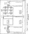
- Typical motor drive systems consist of a simple motor driven by an inverter as shown in Figure 1 .
- Safety critical aerospace applications require a certain number of redundancies designed into the system architecture and this cannot be achieved using the simplex motor drive architecture shown in Figure 1 .
- Figure 2 shows a dual channel three phase fault tolerant motor drive system. Other numbers of multiple channels can also be used.
- permanent magnet motors are used since they have a very good torque / power density ratio in comparison to other motor drive alternatives such as switched reluctance or induction motors.
- the issue with a permanent magnet solution is that the magnets' field cannot be switched off under failure of either the motor or the drive, and one of the most severe failures is a motor winding, or inverter switch being shorted.
- Multi-channel motor drive systems can be used in an active/active or active/standby configuration. In both cases if a failure occurs either within the motor or the drive circuit, then the remaining healthy channels need to maintain the functionality of the system.
- the deactivated, faulty channel or lane will, even though not selected to be the driving lane, still have some effect on the motor. Some current will continue to flow to the motor from this lane due to the motor windings inducing a voltage due to the rotor magnet rotational speed. The reason is that with a permanent magnet motor, the magnets' field cannot be switched off under failure of the drive. These voltages will induce currents which will induce drag torque.
- the present invention aims to provide a multi-channel motor drive system for a permanent magnet motor that actually minimises drag torque when a faulty lane is deactivated, meaning that the steps needed to compensate for drag torque, in the activate lane, are less onerous and the lanes can, therefore, be smaller in size.
- a motor drive circuit comprising two or more inverters to provide current to a permanent magnet motor, each inverter comprising a respective switch arm comprising one or more switches, for each phase of the motor to be driven; the motor drive circuit comprising means for detecting a switch short circuit for any switch within one of the inverters and means for determining the speed of the motor, the motor drive circuit further comprising a controller configured to short circuit each switch arm of the inverter containing the switch short circuit if the motor speed exceeds a predetermined threshold, but not if the motor speed does not exceed the predetermined threshold.
- the invention provides a method of controlling a motor drive circuit for driving a permanent magnet motor, the method comprising short circuiting all motor phases of a motor connected to an inverter in response to detection of both: i) a switch short circuit in any switch in the inverter, and ii) the motor speed exceeding a predetermined threshold.
- an inverter switch is shorted due to a failure, in the first lane, this lane will be deactivated and another lane will be switched ON to drive the motor.
- the motor speed is known. If the motor speed is below a given speed N_tran, the system will continue to operate as in the prior art systems, where current will be increased in the remaining healthy channel(s) to overcome drag produced by the faulty switch and maintain performance. If, on the other hand, the motor speed is greater than N_tran, according to the present invention, the other inverter switches of the faulty lane will also be closed - i.e. shorted. This reduces drag torque and minimises power loss, hence reducing the overload requirements on the remaining healthy lane(s). This topology can maintain operation until the faulty inverter is repaired.
- switch 1 of Figure 2 If, for example, switch 1 of Figure 2 is shorted, then by closing switches 3 and 5, the three phases of the motor will be shorted. On the other hand, if a lower switch (4, 6 or 2) is shorted, then by closing the remaining two switches on the lower leg of the inverter, the three motor phase windings are shorted.
- a fault - a short circuit in switch 1 - is detected in the inverter shown to the left of the diagram.
- This inverter is then deactivated and control is switched over to the healthy inverter.
- n represents the number of channels in a multiple three phase system.
- the invention can also apply to n+1 architectures (as shown in Fig. 6 ), where n represents the number of channels in a multiple single phase system.
- Fig. 6 shows a multi-channel drive for a single phase motor. Here, four switches are required.
- the general operation is the same as for the multi-phase drives described above.
- This method of control enables the reduction of the size and weight of the system for fault tolerant motor drive architectures.
Landscapes
- Engineering & Computer Science (AREA)
- Power Engineering (AREA)
- Control Of Ac Motors In General (AREA)
Abstract
Description
- The present invention is concerned with controlling a motor drive in the event of inverter switch failure.
- Typical motor drive systems consist of a simple motor driven by an inverter as shown in
Figure 1 . Safety critical aerospace applications require a certain number of redundancies designed into the system architecture and this cannot be achieved using the simplex motor drive architecture shown inFigure 1 . - These redundancies have been provided by multi-channel motor drive designs as shown, for example, in
Figure 2. Figure 2 shows a dual channel three phase fault tolerant motor drive system. Other numbers of multiple channels can also be used. - To keep weight and size to the lowest level, permanent magnet motors are used since they have a very good torque / power density ratio in comparison to other motor drive alternatives such as switched reluctance or induction motors. The issue with a permanent magnet solution is that the magnets' field cannot be switched off under failure of either the motor or the drive, and one of the most severe failures is a motor winding, or inverter switch being shorted.
- Multi-channel motor drive systems can be used in an active/active or active/standby configuration. In both cases if a failure occurs either within the motor or the drive circuit, then the remaining healthy channels need to maintain the functionality of the system.
- In the event of an inverter switch becoming shorted in one of the channels or lanes, that particular channel or lane will be switched off or deactivated and one of the other channels or lanes, e.g. a lane which was in stand-by mode, will be (or will remain) activated to drive the motor.
- Whilst this provides improved safety in the event of a failure, the deactivated, faulty channel or lane will, even though not selected to be the driving lane, still have some effect on the motor. Some current will continue to flow to the motor from this lane due to the motor windings inducing a voltage due to the rotor magnet rotational speed. The reason is that with a permanent magnet motor, the magnets' field cannot be switched off under failure of the drive. These voltages will induce currents which will induce drag torque.
- Knowing this, designers of these multi-channel systems must design the channels such that if one fails, the channel(s) taking over as the driving channel(s) can compensate for this drag torque and associated power losses. In case of an inverter switch being shorted, the system will detect the failure, and the faulty inverter will be deactivated. By doing so the lane with the faulty inverter will not be able to produce positive torque, and the whole motor drive lane will be considered faulty. In order to maintain performance, the remaining healthy channels need to increase their torque by 1/n. This can be achieved by increasing the current in each channel by 1/n (if steel material saturation is ignored). In addition, however, the motor windings connected to the faulty inverter channel will induce a voltage due to the rotor magnet rotational speed. These voltages will induce currents, which will induce drag torque. This phenomenon is illustrated in
Figure 3 for a two three-phase channel motor drive system for the condition where the induced voltage of phase b is greater than that of phase a, but the idea can be generalised for any n three-phase channel system. The circulating currents will induce a drag torque that the remaining healthy channels need to overcome.Figure 4 shows the drag torque produced from the shorted switch, and the power loss in the motor windings. This design consideration means that the drive channels have to be greater in size than if they did not have to compensate the drag torque. - The present invention aims to provide a multi-channel motor drive system for a permanent magnet motor that actually minimises drag torque when a faulty lane is deactivated, meaning that the steps needed to compensate for drag torque, in the activate lane, are less onerous and the lanes can, therefore, be smaller in size.
- According to an aspect of the present invention, there is provided a motor drive circuit comprising two or more inverters to provide current to a permanent magnet motor, each inverter comprising a respective switch arm comprising one or more switches, for each phase of the motor to be driven; the motor drive circuit comprising means for detecting a switch short circuit for any switch within one of the inverters and means for determining the speed of the motor, the motor drive circuit further comprising a controller configured to short circuit each switch arm of the inverter containing the switch short circuit if the motor speed exceeds a predetermined threshold, but not if the motor speed does not exceed the predetermined threshold.
- According to a second aspect, the invention provides a method of controlling a motor drive circuit for driving a permanent magnet motor, the method comprising short circuiting all motor phases of a motor connected to an inverter in response to detection of both: i) a switch short circuit in any switch in the inverter, and ii) the motor speed exceeding a predetermined threshold.
- According to the present invention, in the preferred embodiment, if an inverter switch is shorted due to a failure, in the first lane, this lane will be deactivated and another lane will be switched ON to drive the motor. As mentioned above, although the faulty lane has been deactivated, this will still give rise to some drag torque. According to the present invention, the motor speed is known. If the motor speed is below a given speed N_tran, the system will continue to operate as in the prior art systems, where current will be increased in the remaining healthy channel(s) to overcome drag produced by the faulty switch and maintain performance. If, on the other hand, the motor speed is greater than N_tran, according to the present invention, the other inverter switches of the faulty lane will also be closed - i.e. shorted. This reduces drag torque and minimises power loss, hence reducing the overload requirements on the remaining healthy lane(s). This topology can maintain operation until the faulty inverter is repaired.
- This operation can be described with reference to
Figure 5 . - Preferred embodiments will now be described by way of example only, with reference to the drawings.
-
Figure 1 is a block diagram of a typical 3-phase motor drive system; -
Figures 2 and3 are block diagrams of a multi-channel, 3-phase (3+3) motor drive system; -
Figures 4 and5 show drag torque and ohmic losses occurring when a single or three-switch short circuits; -
Figure 6 is a circuit diagram for a multichannel, singe phase motor drive system. -
Figure 5 shows drag torque and ohmic loss in systems operating as described in relation to the prior art, in the event of an inverter switch short-circuit failure.Figure 5 also shows, in contrast, the ohmic loss and drag torque characteristics if the other switches of the faulty inverter are closed or shorted. - As can be seen from
Figure 5 , below motor speed N_tran, the ohmic losses for a system where all of the inverter switches are shorted, in the case of a faulty inverter switch, within a given lane, are very high but, for this mode of operation, after the speed has increased to beyond N_tran, the losses sink considerably. On the other hand, for speeds below N_tran, the losses in the prior art systems are comparatively less, but are higher at higher speeds. This effect is taken into account when operating the invention such that, according to motor speed, an appropriate mode is selected. The present invention reads the motor speed and the controller decides whether to short the phases of the motor connected to the faulty inverter or continue to work as it is. The transition speed is N_trans. If the present invention were not brought into effect, at these higher speeds, an inverter switch short-circuit would result in a high level of drag torque and extremely high losses. By shorting all of the motor phases in the faulty lane, at speeds greater than N_tran, drag torque and losses are greatly reduced and the system can, accordingly, be smaller in size. - If, for example,
switch 1 ofFigure 2 is shorted, then byclosing switches - This can also be seen with reference to
Figure 3 . Here, for a three-phase motor, two inverters are provided to allow switching to a "healthy" inverter in the event of one inverter being faulty. - In the example shown, a fault - a short circuit in switch 1 - is detected in the inverter shown to the left of the diagram.
- This inverter is then deactivated and control is switched over to the healthy inverter.
- As mentioned above, a problem is that even though the "faulty inverter" is no longer driving the motor, there will still be some residual loss and drag torque effects from it.
- As can be seen in
Figure 5 , and as described above, at lower motor speeds, the ohmic losses and drag torque are minimised by not closing other (non-shorted) switches of the faulty inverter, but above a certain motor speed N_tran, the loss/drag torque characteristics change and are significantly reduced if the feature of the present invention is implemented, namely that the other switches (in the example shown -switches 3 and 5) are also shorted. - The description is presented in relation to a so-called 3n+3 architecture, where n represents the number of channels in a multiple three phase system. The invention can also apply to n+1 architectures (as shown in
Fig. 6 ), where n represents the number of channels in a multiple single phase system.Fig. 6 , for example, shows a multi-channel drive for a single phase motor. Here, four switches are required. The general operation, however, is the same as for the multi-phase drives described above. - This method of control enables the reduction of the size and weight of the system for fault tolerant motor drive architectures.
Claims (4)
- A motor drive circuit comprising two or more inverters to provide current to a permanent magnet motor, each inverter comprising a respective switch arm comprising one or more switches, for each phase of the motor to be driven; the motor drive circuit comprising means for detecting a switch short circuit for any switch within one of the inverters and means for determining the speed of the motor, the motor drive circuit further comprising a controller configured to short circuit each switch arm of the inverter containing the switch short circuit if the motor speed exceeds a predetermined threshold, but not if the motor speed does not exceed the predetermined threshold.
- A method of controlling a motor drive circuit for driving a permanent magnet motor, the method comprising short circuiting all motor phases of a motor connected to an inverter in response to detection of both: i) a switch short circuit in any switch in the inverter, and ii) the motor speed exceeding a predetermined threshold.
- A motor drive circuit as claimed in claim 1, for use with a three-phase motor, comprising two or more inverters each comprising three switch arms.
- The motor drive circuit of claim 4, wherein each switch arm comprises two switches connected in series.
Priority Applications (2)
| Application Number | Priority Date | Filing Date | Title |
|---|---|---|---|
| EP15180405.1A EP3131198B1 (en) | 2015-08-10 | 2015-08-10 | Control strategy of a dual lane fault tolerant permanent magnet motor to reduce drag torque under fault condition |
| US15/229,442 US10320183B2 (en) | 2015-08-10 | 2016-08-05 | Control strategy of a dual lane fault tolerant permanent magnet motor to reduce drag torque under fault condition |
Applications Claiming Priority (1)
| Application Number | Priority Date | Filing Date | Title |
|---|---|---|---|
| EP15180405.1A EP3131198B1 (en) | 2015-08-10 | 2015-08-10 | Control strategy of a dual lane fault tolerant permanent magnet motor to reduce drag torque under fault condition |
Publications (2)
| Publication Number | Publication Date |
|---|---|
| EP3131198A1 true EP3131198A1 (en) | 2017-02-15 |
| EP3131198B1 EP3131198B1 (en) | 2022-06-08 |
Family
ID=53794122
Family Applications (1)
| Application Number | Title | Priority Date | Filing Date |
|---|---|---|---|
| EP15180405.1A Active EP3131198B1 (en) | 2015-08-10 | 2015-08-10 | Control strategy of a dual lane fault tolerant permanent magnet motor to reduce drag torque under fault condition |
Country Status (2)
| Country | Link |
|---|---|
| US (1) | US10320183B2 (en) |
| EP (1) | EP3131198B1 (en) |
Cited By (9)
| Publication number | Priority date | Publication date | Assignee | Title |
|---|---|---|---|---|
| CN108039837A (en) * | 2017-12-15 | 2018-05-15 | 长安大学 | A kind of double permanent magnet synchronous motor Fault tolerant inverters and its control method |
| CN108429491A (en) * | 2018-03-14 | 2018-08-21 | 长安大学 | A fault-tolerant control system and control method for double permanent magnet synchronous motors |
| CN108616214A (en) * | 2018-05-19 | 2018-10-02 | 哈尔滨工业大学 | A kind of driving topology for eliminating double three-phase machine PWM frequency noise |
| CN112332735A (en) * | 2020-09-16 | 2021-02-05 | 江苏大学 | Fault-tolerant control method under single-phase open-circuit fault of 3X 3-phase permanent magnet auxiliary synchronous reluctance motor |
| CN113193813A (en) * | 2021-05-13 | 2021-07-30 | 哈尔滨工业大学 | Five-phase permanent magnet motor short-circuit fault-tolerant control method for reconstructing circular rotary magnetomotive force |
| US20220255482A1 (en) * | 2021-02-10 | 2022-08-11 | Blue Origin, Llc | Low-voltage fault-tolerant rotating electromechanical actuators, and associated systems and methods |
| US11768088B2 (en) | 2020-06-11 | 2023-09-26 | Blue Origin, Llc | Voltage-current phase-based method for linear and rotary transformer systems, and associated systems and methods |
| US11987395B2 (en) | 2021-06-07 | 2024-05-21 | Blue Origin, Llc | Thrusting rails for launch vehicles, and associated systems and methods |
| EP4465521A1 (en) * | 2023-05-16 | 2024-11-20 | Goodrich Actuation Systems Limited | Control scheme for starting dual channel permanent magnet motor drive system under ossc fault of one channel |
Families Citing this family (8)
| Publication number | Priority date | Publication date | Assignee | Title |
|---|---|---|---|---|
| EP3131198B1 (en) * | 2015-08-10 | 2022-06-08 | Goodrich Actuation Systems Limited | Control strategy of a dual lane fault tolerant permanent magnet motor to reduce drag torque under fault condition |
| GB2563028B (en) * | 2017-05-30 | 2020-06-24 | Protean Electric Ltd | A controller for an electric machine |
| GB2599586B (en) * | 2020-10-27 | 2023-02-01 | Univ Jiangsu | Short-circuit fault-tolerant control method based on deadbeat current tracking for five-phase permanent magnet motor with sinusoidal back-electromotive |
| CN112290859B (en) * | 2020-10-27 | 2022-05-20 | 江苏大学 | Five-phase permanent magnet motor short-circuit fault-tolerant control method adopting dead-beat current tracking |
| CN113179074B (en) * | 2021-05-13 | 2022-07-12 | 哈尔滨工业大学 | Five-phase permanent magnet motor short-circuit fault tolerance control method without constraint of d-axis armature magnetomotive force |
| EP4160902A1 (en) | 2021-09-30 | 2023-04-05 | Goodrich Actuation Systems Limited | Fault tolerant converter topology |
| EP4451550A1 (en) | 2023-04-20 | 2024-10-23 | Goodrich Actuation Systems Limited | Control scheme for fault tolerant converter topology based dual channel permanent magnet motor drive system |
| EP4683204A1 (en) | 2024-07-19 | 2026-01-21 | Goodrich Actuation Systems Limited | Dc bus over-voltage protection scheme for fault tolerant permanent magnet motor drives |
Citations (4)
| Publication number | Priority date | Publication date | Assignee | Title |
|---|---|---|---|---|
| EP0588628A1 (en) * | 1992-09-17 | 1994-03-23 | Hitachi, Ltd. | Electric vehicle control system |
| US6239566B1 (en) * | 1998-05-12 | 2001-05-29 | Mannesmann Sachs Ag | Drive system for a permanently excited electric motor having at least one phase winding |
| US20140191700A1 (en) * | 2011-08-18 | 2014-07-10 | Robert Bosch Gmbh | Operating state circuit for inverter and method for setting operating states of an inverter |
| WO2014177907A1 (en) * | 2013-04-30 | 2014-11-06 | Freescale Semiconductor, Inc. | Device for controlling a multi-phase motor |
Family Cites Families (39)
| Publication number | Priority date | Publication date | Assignee | Title |
|---|---|---|---|---|
| EP0640507B1 (en) * | 1992-05-12 | 2003-04-16 | Seiko Epson Corporation | Electric vehicle |
| US5469351A (en) * | 1994-07-05 | 1995-11-21 | Ford Motor Company | Fault isolation in an induction motor control system |
| US6683435B1 (en) * | 2002-06-21 | 2004-01-27 | Ford Motor Company | Electrical machine drive method and system |
| US7227331B2 (en) * | 2005-02-14 | 2007-06-05 | International Rectifier Corporation | Safety interlock and protection circuit for permanent magnet motor drive |
| US7554276B2 (en) * | 2005-09-21 | 2009-06-30 | International Rectifier Corporation | Protection circuit for permanent magnet synchronous motor in field weakening operation |
| US7279862B1 (en) * | 2006-08-04 | 2007-10-09 | Gm Global Technology Operations, Inc. | Fault handling of inverter driven PM motor drives |
| JP4757815B2 (en) * | 2007-03-05 | 2011-08-24 | 本田技研工業株式会社 | Electric motor control device and vehicle |
| CN101595633B (en) * | 2007-04-16 | 2012-06-06 | 三菱电机株式会社 | Electric motor control apparatus |
| JP4609474B2 (en) * | 2007-10-10 | 2011-01-12 | 株式会社デンソー | Rotating electrical machine equipment |
| JP4240149B1 (en) * | 2008-02-14 | 2009-03-18 | トヨタ自動車株式会社 | Motor drive device and hybrid drive device |
| DE102008037064A1 (en) * | 2008-08-08 | 2010-02-11 | Bayerische Motoren Werke Aktiengesellschaft | Circuit arrangement for an electric drive |
| JP4968698B2 (en) * | 2008-12-26 | 2012-07-04 | 本田技研工業株式会社 | Electric motor control device |
| JP5315155B2 (en) * | 2009-07-23 | 2013-10-16 | 日立オートモティブシステムズ株式会社 | Semiconductor element control device, automotive electrical system |
| JP2011045212A (en) * | 2009-08-24 | 2011-03-03 | Denso Corp | Drive controller |
| FR2955719B1 (en) * | 2010-01-28 | 2012-02-24 | Hispano Suiza Sa | METHOD AND DEVICE FOR CONTROLLING POLYPHASE ELECTRIC MACHINE |
| FR2961361B1 (en) * | 2010-06-14 | 2013-07-12 | Hispano Suiza Sa | VOLTAGE INVERTER AND METHOD FOR CONTROLLING SUCH AS INVERTER |
| DE102010030856A1 (en) * | 2010-07-02 | 2012-01-05 | Robert Bosch Gmbh | Method for operating an at least three-phase electric machine serving as drive unit in a motor vehicle and control unit for an inverter |
| JP2012070263A (en) * | 2010-09-24 | 2012-04-05 | Denso Corp | Electronic device |
| DE102010060380B3 (en) * | 2010-11-05 | 2012-02-02 | Lti Drives Gmbh | Emergency-operated pitch motor drive circuit |
| JP5352570B2 (en) * | 2010-12-13 | 2013-11-27 | 株式会社日立製作所 | Rotating machine control device, rotating machine system, vehicle, electric vehicle or power generation system |
| US8508180B2 (en) * | 2011-02-03 | 2013-08-13 | Panasonic Corporation | Motor drive apparatus |
| KR102035358B1 (en) * | 2011-05-24 | 2019-10-22 | 콘티넨탈 오토모티브 게엠베하 | Method and device for operating a brushless motor |
| WO2013008313A1 (en) * | 2011-07-12 | 2013-01-17 | トヨタ自動車株式会社 | Vehicle and vehicle control method |
| US9042146B2 (en) * | 2011-11-14 | 2015-05-26 | Rockwell Automation Technologies, Inc. | DC pre-charge circuit |
| JP5622053B2 (en) * | 2012-02-09 | 2014-11-12 | 株式会社デンソー | Control device for multi-phase rotating machine and electric power steering device using the same |
| US8872455B2 (en) * | 2012-05-22 | 2014-10-28 | Deere & Company | Method and controller for an electric motor with fault detection |
| US9291678B2 (en) * | 2012-05-31 | 2016-03-22 | Deere & Company | Method and controller for an electric motor with switch testing |
| JP5590076B2 (en) * | 2012-07-04 | 2014-09-17 | 株式会社デンソー | Control device for multi-phase rotating machine |
| JP5606506B2 (en) * | 2012-09-20 | 2014-10-15 | 三菱電機株式会社 | Drive control device and drive control method |
| JP5614661B2 (en) * | 2012-10-09 | 2014-10-29 | 株式会社デンソー | Rotating electrical machine control device and electric power steering device using the same |
| JPWO2015022718A1 (en) * | 2013-08-12 | 2017-03-02 | 日本精工株式会社 | Motor control device, electric power steering device using the same, and vehicle |
| WO2015087553A1 (en) * | 2013-12-13 | 2015-06-18 | 日本精工株式会社 | Electronic control unit, electric power steering device, and vehicle |
| JP6220696B2 (en) * | 2014-02-19 | 2017-10-25 | 日立オートモティブシステムズ株式会社 | Electric motor drive control device |
| JP6362349B2 (en) * | 2014-02-19 | 2018-07-25 | 日立オートモティブシステムズ株式会社 | Electric motor drive control device |
| CN105934879B (en) * | 2014-03-11 | 2018-09-14 | 日本精工株式会社 | Motor control device, electric power steering device using same, and vehicle |
| JP6211443B2 (en) * | 2014-03-14 | 2017-10-11 | 日立オートモティブシステムズ株式会社 | Electric motor control device |
| JP6188928B2 (en) * | 2014-04-23 | 2017-08-30 | 三菱電機株式会社 | AC rotating machine control device |
| EP3131198B1 (en) * | 2015-08-10 | 2022-06-08 | Goodrich Actuation Systems Limited | Control strategy of a dual lane fault tolerant permanent magnet motor to reduce drag torque under fault condition |
| JP6252569B2 (en) * | 2015-09-10 | 2017-12-27 | トヨタ自動車株式会社 | Hybrid vehicle |
-
2015
- 2015-08-10 EP EP15180405.1A patent/EP3131198B1/en active Active
-
2016
- 2016-08-05 US US15/229,442 patent/US10320183B2/en active Active
Patent Citations (4)
| Publication number | Priority date | Publication date | Assignee | Title |
|---|---|---|---|---|
| EP0588628A1 (en) * | 1992-09-17 | 1994-03-23 | Hitachi, Ltd. | Electric vehicle control system |
| US6239566B1 (en) * | 1998-05-12 | 2001-05-29 | Mannesmann Sachs Ag | Drive system for a permanently excited electric motor having at least one phase winding |
| US20140191700A1 (en) * | 2011-08-18 | 2014-07-10 | Robert Bosch Gmbh | Operating state circuit for inverter and method for setting operating states of an inverter |
| WO2014177907A1 (en) * | 2013-04-30 | 2014-11-06 | Freescale Semiconductor, Inc. | Device for controlling a multi-phase motor |
Cited By (16)
| Publication number | Priority date | Publication date | Assignee | Title |
|---|---|---|---|---|
| CN108039837A (en) * | 2017-12-15 | 2018-05-15 | 长安大学 | A kind of double permanent magnet synchronous motor Fault tolerant inverters and its control method |
| CN108429491A (en) * | 2018-03-14 | 2018-08-21 | 长安大学 | A fault-tolerant control system and control method for double permanent magnet synchronous motors |
| CN108429491B (en) * | 2018-03-14 | 2021-03-16 | 长安大学 | Fault-tolerant control system and method for double permanent magnet synchronous motors |
| CN108616214A (en) * | 2018-05-19 | 2018-10-02 | 哈尔滨工业大学 | A kind of driving topology for eliminating double three-phase machine PWM frequency noise |
| US12163810B2 (en) | 2020-06-11 | 2024-12-10 | Blue Origin, Llc | Voltage-current phase-based method for linear and rotary transformer systems, and associated systems and methods |
| US11768088B2 (en) | 2020-06-11 | 2023-09-26 | Blue Origin, Llc | Voltage-current phase-based method for linear and rotary transformer systems, and associated systems and methods |
| CN112332735A (en) * | 2020-09-16 | 2021-02-05 | 江苏大学 | Fault-tolerant control method under single-phase open-circuit fault of 3X 3-phase permanent magnet auxiliary synchronous reluctance motor |
| CN112332735B (en) * | 2020-09-16 | 2022-06-21 | 江苏大学 | Fault-tolerant control method of 3X 3-phase permanent magnet auxiliary synchronous reluctance motor |
| US20220255482A1 (en) * | 2021-02-10 | 2022-08-11 | Blue Origin, Llc | Low-voltage fault-tolerant rotating electromechanical actuators, and associated systems and methods |
| US11936317B2 (en) * | 2021-02-10 | 2024-03-19 | Blue Origin, Llc | Low-voltage fault-tolerant rotating electromechanical actuators, and associated systems and methods |
| US12519411B2 (en) | 2021-02-10 | 2026-01-06 | Blue Origin Manufacturing, LLC | Low-voltage fault-tolerant rotating electromechanical actuators, and associated systems and methods |
| CN113193813B (en) * | 2021-05-13 | 2022-07-12 | 哈尔滨工业大学 | Five-phase permanent magnet motor short-circuit fault-tolerant control method for reconstructing circular rotary magnetomotive force |
| CN113193813A (en) * | 2021-05-13 | 2021-07-30 | 哈尔滨工业大学 | Five-phase permanent magnet motor short-circuit fault-tolerant control method for reconstructing circular rotary magnetomotive force |
| US11987395B2 (en) | 2021-06-07 | 2024-05-21 | Blue Origin, Llc | Thrusting rails for launch vehicles, and associated systems and methods |
| US12509249B2 (en) | 2021-06-07 | 2025-12-30 | Blue Origin Manufacturing, LLC | Thrusting rails for launch vehicles, and associated systems and methods |
| EP4465521A1 (en) * | 2023-05-16 | 2024-11-20 | Goodrich Actuation Systems Limited | Control scheme for starting dual channel permanent magnet motor drive system under ossc fault of one channel |
Also Published As
| Publication number | Publication date |
|---|---|
| US10320183B2 (en) | 2019-06-11 |
| US20170047728A1 (en) | 2017-02-16 |
| EP3131198B1 (en) | 2022-06-08 |
Similar Documents
| Publication | Publication Date | Title |
|---|---|---|
| EP3131198B1 (en) | Control strategy of a dual lane fault tolerant permanent magnet motor to reduce drag torque under fault condition | |
| EP3772817B1 (en) | Solid state phase isolation of multi-phase motors | |
| US10305368B2 (en) | Method and apparatus for bypassing Cascaded H-Bridge (CHB) power cells and power sub cell for multilevel inverter | |
| EP3480937B1 (en) | Counter-field winding in electrical generator | |
| US5499186A (en) | Three-phase power converter with fail soft characteristics | |
| EP3966906B1 (en) | System and method for shared hybrid transfer switch | |
| US20250343478A1 (en) | Fault tolerant converter topology | |
| US9203341B2 (en) | Switch arrangement | |
| JP2006311692A (en) | Railway vehicle drive control device | |
| Ma et al. | A fault-tolerant control strategy for switched reluctance motor drive for electric vehicles under short-fault condition | |
| CA2773830A1 (en) | Electric machine assembly with fail-safe arrangement | |
| US20140132125A1 (en) | Electrical machine comprising a safety circuit | |
| US10978982B2 (en) | Method and device for operating an electronically commutated electrical machine in the event of a fault | |
| KR20150064562A (en) | Motor driving apparatus and motor driving method | |
| JP2015097222A (en) | Superconducting magnet | |
| EP3255779B1 (en) | Reconfigurable multi-permanent magnet generator based power generating system | |
| JP2008104276A (en) | Inverter device | |
| JP7805439B2 (en) | Drive circuit | |
| US20240356478A1 (en) | Control scheme for fault tolerant converter topology based dual channel permanent magnet motor drive system | |
| KR102731027B1 (en) | A semiconductor circuit breaker having a semiconductor switch for power and a power supply system including the semiconductor circuit breaker | |
| US20240128911A1 (en) | Motor winding neutral switching | |
| US20240388232A1 (en) | Control scheme for starting dual channel permanent magnet motor drive system under ossc fault of one channel | |
| WO2022269823A1 (en) | Discharge control circuit and motor system |
Legal Events
| Date | Code | Title | Description |
|---|---|---|---|
| PUAI | Public reference made under article 153(3) epc to a published international application that has entered the european phase |
Free format text: ORIGINAL CODE: 0009012 |
|
| STAA | Information on the status of an ep patent application or granted ep patent |
Free format text: STATUS: THE APPLICATION HAS BEEN PUBLISHED |
|
| AK | Designated contracting states |
Kind code of ref document: A1 Designated state(s): AL AT BE BG CH CY CZ DE DK EE ES FI FR GB GR HR HU IE IS IT LI LT LU LV MC MK MT NL NO PL PT RO RS SE SI SK SM TR |
|
| AX | Request for extension of the european patent |
Extension state: BA ME |
|
| STAA | Information on the status of an ep patent application or granted ep patent |
Free format text: STATUS: REQUEST FOR EXAMINATION WAS MADE |
|
| 17P | Request for examination filed |
Effective date: 20170814 |
|
| RBV | Designated contracting states (corrected) |
Designated state(s): AL AT BE BG CH CY CZ DE DK EE ES FI FR GB GR HR HU IE IS IT LI LT LU LV MC MK MT NL NO PL PT RO RS SE SI SK SM TR |
|
| STAA | Information on the status of an ep patent application or granted ep patent |
Free format text: STATUS: EXAMINATION IS IN PROGRESS |
|
| 17Q | First examination report despatched |
Effective date: 20200213 |
|
| REG | Reference to a national code |
Ref country code: DE Ref legal event code: R079 Ref document number: 602015079323 Country of ref document: DE Free format text: PREVIOUS MAIN CLASS: H02P0029020000 Ipc: H02P0027060000 |
|
| GRAP | Despatch of communication of intention to grant a patent |
Free format text: ORIGINAL CODE: EPIDOSNIGR1 |
|
| STAA | Information on the status of an ep patent application or granted ep patent |
Free format text: STATUS: GRANT OF PATENT IS INTENDED |
|
| RIC1 | Information provided on ipc code assigned before grant |
Ipc: H02P 29/028 20160101ALI20211213BHEP Ipc: H02P 29/024 20160101ALI20211213BHEP Ipc: H02P 27/06 20060101AFI20211213BHEP |
|
| INTG | Intention to grant announced |
Effective date: 20220104 |
|
| GRAS | Grant fee paid |
Free format text: ORIGINAL CODE: EPIDOSNIGR3 |
|
| GRAA | (expected) grant |
Free format text: ORIGINAL CODE: 0009210 |
|
| STAA | Information on the status of an ep patent application or granted ep patent |
Free format text: STATUS: THE PATENT HAS BEEN GRANTED |
|
| AK | Designated contracting states |
Kind code of ref document: B1 Designated state(s): AL AT BE BG CH CY CZ DE DK EE ES FI FR GB GR HR HU IE IS IT LI LT LU LV MC MK MT NL NO PL PT RO RS SE SI SK SM TR |
|
| REG | Reference to a national code |
Ref country code: GB Ref legal event code: FG4D |
|
| REG | Reference to a national code |
Ref country code: AT Ref legal event code: REF Ref document number: 1497616 Country of ref document: AT Kind code of ref document: T Effective date: 20220615 Ref country code: CH Ref legal event code: EP |
|
| REG | Reference to a national code |
Ref country code: DE Ref legal event code: R096 Ref document number: 602015079323 Country of ref document: DE |
|
| REG | Reference to a national code |
Ref country code: IE Ref legal event code: FG4D |
|
| REG | Reference to a national code |
Ref country code: LT Ref legal event code: MG9D |
|
| REG | Reference to a national code |
Ref country code: NL Ref legal event code: MP Effective date: 20220608 |
|
| PG25 | Lapsed in a contracting state [announced via postgrant information from national office to epo] |
Ref country code: SE Free format text: LAPSE BECAUSE OF FAILURE TO SUBMIT A TRANSLATION OF THE DESCRIPTION OR TO PAY THE FEE WITHIN THE PRESCRIBED TIME-LIMIT Effective date: 20220608 Ref country code: NO Free format text: LAPSE BECAUSE OF FAILURE TO SUBMIT A TRANSLATION OF THE DESCRIPTION OR TO PAY THE FEE WITHIN THE PRESCRIBED TIME-LIMIT Effective date: 20220908 Ref country code: LT Free format text: LAPSE BECAUSE OF FAILURE TO SUBMIT A TRANSLATION OF THE DESCRIPTION OR TO PAY THE FEE WITHIN THE PRESCRIBED TIME-LIMIT Effective date: 20220608 Ref country code: HR Free format text: LAPSE BECAUSE OF FAILURE TO SUBMIT A TRANSLATION OF THE DESCRIPTION OR TO PAY THE FEE WITHIN THE PRESCRIBED TIME-LIMIT Effective date: 20220608 Ref country code: GR Free format text: LAPSE BECAUSE OF FAILURE TO SUBMIT A TRANSLATION OF THE DESCRIPTION OR TO PAY THE FEE WITHIN THE PRESCRIBED TIME-LIMIT Effective date: 20220909 Ref country code: FI Free format text: LAPSE BECAUSE OF FAILURE TO SUBMIT A TRANSLATION OF THE DESCRIPTION OR TO PAY THE FEE WITHIN THE PRESCRIBED TIME-LIMIT Effective date: 20220608 Ref country code: ES Free format text: LAPSE BECAUSE OF FAILURE TO SUBMIT A TRANSLATION OF THE DESCRIPTION OR TO PAY THE FEE WITHIN THE PRESCRIBED TIME-LIMIT Effective date: 20220608 Ref country code: BG Free format text: LAPSE BECAUSE OF FAILURE TO SUBMIT A TRANSLATION OF THE DESCRIPTION OR TO PAY THE FEE WITHIN THE PRESCRIBED TIME-LIMIT Effective date: 20220908 |
|
| REG | Reference to a national code |
Ref country code: AT Ref legal event code: MK05 Ref document number: 1497616 Country of ref document: AT Kind code of ref document: T Effective date: 20220608 |
|
| PG25 | Lapsed in a contracting state [announced via postgrant information from national office to epo] |
Ref country code: RS Free format text: LAPSE BECAUSE OF FAILURE TO SUBMIT A TRANSLATION OF THE DESCRIPTION OR TO PAY THE FEE WITHIN THE PRESCRIBED TIME-LIMIT Effective date: 20220608 Ref country code: LV Free format text: LAPSE BECAUSE OF FAILURE TO SUBMIT A TRANSLATION OF THE DESCRIPTION OR TO PAY THE FEE WITHIN THE PRESCRIBED TIME-LIMIT Effective date: 20220608 |
|
| PG25 | Lapsed in a contracting state [announced via postgrant information from national office to epo] |
Ref country code: NL Free format text: LAPSE BECAUSE OF FAILURE TO SUBMIT A TRANSLATION OF THE DESCRIPTION OR TO PAY THE FEE WITHIN THE PRESCRIBED TIME-LIMIT Effective date: 20220608 |
|
| PG25 | Lapsed in a contracting state [announced via postgrant information from national office to epo] |
Ref country code: SM Free format text: LAPSE BECAUSE OF FAILURE TO SUBMIT A TRANSLATION OF THE DESCRIPTION OR TO PAY THE FEE WITHIN THE PRESCRIBED TIME-LIMIT Effective date: 20220608 Ref country code: SK Free format text: LAPSE BECAUSE OF FAILURE TO SUBMIT A TRANSLATION OF THE DESCRIPTION OR TO PAY THE FEE WITHIN THE PRESCRIBED TIME-LIMIT Effective date: 20220608 Ref country code: RO Free format text: LAPSE BECAUSE OF FAILURE TO SUBMIT A TRANSLATION OF THE DESCRIPTION OR TO PAY THE FEE WITHIN THE PRESCRIBED TIME-LIMIT Effective date: 20220608 Ref country code: PT Free format text: LAPSE BECAUSE OF FAILURE TO SUBMIT A TRANSLATION OF THE DESCRIPTION OR TO PAY THE FEE WITHIN THE PRESCRIBED TIME-LIMIT Effective date: 20221010 Ref country code: EE Free format text: LAPSE BECAUSE OF FAILURE TO SUBMIT A TRANSLATION OF THE DESCRIPTION OR TO PAY THE FEE WITHIN THE PRESCRIBED TIME-LIMIT Effective date: 20220608 Ref country code: CZ Free format text: LAPSE BECAUSE OF FAILURE TO SUBMIT A TRANSLATION OF THE DESCRIPTION OR TO PAY THE FEE WITHIN THE PRESCRIBED TIME-LIMIT Effective date: 20220608 Ref country code: AT Free format text: LAPSE BECAUSE OF FAILURE TO SUBMIT A TRANSLATION OF THE DESCRIPTION OR TO PAY THE FEE WITHIN THE PRESCRIBED TIME-LIMIT Effective date: 20220608 |
|
| PG25 | Lapsed in a contracting state [announced via postgrant information from national office to epo] |
Ref country code: PL Free format text: LAPSE BECAUSE OF FAILURE TO SUBMIT A TRANSLATION OF THE DESCRIPTION OR TO PAY THE FEE WITHIN THE PRESCRIBED TIME-LIMIT Effective date: 20220608 Ref country code: IS Free format text: LAPSE BECAUSE OF FAILURE TO SUBMIT A TRANSLATION OF THE DESCRIPTION OR TO PAY THE FEE WITHIN THE PRESCRIBED TIME-LIMIT Effective date: 20221008 |
|
| REG | Reference to a national code |
Ref country code: DE Ref legal event code: R097 Ref document number: 602015079323 Country of ref document: DE |
|
| PG25 | Lapsed in a contracting state [announced via postgrant information from national office to epo] |
Ref country code: MC Free format text: LAPSE BECAUSE OF FAILURE TO SUBMIT A TRANSLATION OF THE DESCRIPTION OR TO PAY THE FEE WITHIN THE PRESCRIBED TIME-LIMIT Effective date: 20220608 Ref country code: AL Free format text: LAPSE BECAUSE OF FAILURE TO SUBMIT A TRANSLATION OF THE DESCRIPTION OR TO PAY THE FEE WITHIN THE PRESCRIBED TIME-LIMIT Effective date: 20220608 |
|
| REG | Reference to a national code |
Ref country code: CH Ref legal event code: PL |
|
| PLBE | No opposition filed within time limit |
Free format text: ORIGINAL CODE: 0009261 |
|
| STAA | Information on the status of an ep patent application or granted ep patent |
Free format text: STATUS: NO OPPOSITION FILED WITHIN TIME LIMIT |
|
| PG25 | Lapsed in a contracting state [announced via postgrant information from national office to epo] |
Ref country code: LU Free format text: LAPSE BECAUSE OF NON-PAYMENT OF DUE FEES Effective date: 20220810 Ref country code: LI Free format text: LAPSE BECAUSE OF NON-PAYMENT OF DUE FEES Effective date: 20220831 Ref country code: DK Free format text: LAPSE BECAUSE OF FAILURE TO SUBMIT A TRANSLATION OF THE DESCRIPTION OR TO PAY THE FEE WITHIN THE PRESCRIBED TIME-LIMIT Effective date: 20220608 Ref country code: CH Free format text: LAPSE BECAUSE OF NON-PAYMENT OF DUE FEES Effective date: 20220831 |
|
| REG | Reference to a national code |
Ref country code: BE Ref legal event code: MM Effective date: 20220831 |
|
| 26N | No opposition filed |
Effective date: 20230310 |
|
| PG25 | Lapsed in a contracting state [announced via postgrant information from national office to epo] |
Ref country code: SI Free format text: LAPSE BECAUSE OF FAILURE TO SUBMIT A TRANSLATION OF THE DESCRIPTION OR TO PAY THE FEE WITHIN THE PRESCRIBED TIME-LIMIT Effective date: 20220608 |
|
| PG25 | Lapsed in a contracting state [announced via postgrant information from national office to epo] |
Ref country code: IE Free format text: LAPSE BECAUSE OF NON-PAYMENT OF DUE FEES Effective date: 20220810 |
|
| P01 | Opt-out of the competence of the unified patent court (upc) registered |
Effective date: 20230706 |
|
| PG25 | Lapsed in a contracting state [announced via postgrant information from national office to epo] |
Ref country code: BE Free format text: LAPSE BECAUSE OF NON-PAYMENT OF DUE FEES Effective date: 20220831 |
|
| PG25 | Lapsed in a contracting state [announced via postgrant information from national office to epo] |
Ref country code: HU Free format text: LAPSE BECAUSE OF FAILURE TO SUBMIT A TRANSLATION OF THE DESCRIPTION OR TO PAY THE FEE WITHIN THE PRESCRIBED TIME-LIMIT; INVALID AB INITIO Effective date: 20150810 |
|
| PG25 | Lapsed in a contracting state [announced via postgrant information from national office to epo] |
Ref country code: CY Free format text: LAPSE BECAUSE OF FAILURE TO SUBMIT A TRANSLATION OF THE DESCRIPTION OR TO PAY THE FEE WITHIN THE PRESCRIBED TIME-LIMIT Effective date: 20220608 |
|
| PG25 | Lapsed in a contracting state [announced via postgrant information from national office to epo] |
Ref country code: MK Free format text: LAPSE BECAUSE OF FAILURE TO SUBMIT A TRANSLATION OF THE DESCRIPTION OR TO PAY THE FEE WITHIN THE PRESCRIBED TIME-LIMIT Effective date: 20220608 |
|
| PG25 | Lapsed in a contracting state [announced via postgrant information from national office to epo] |
Ref country code: MT Free format text: LAPSE BECAUSE OF FAILURE TO SUBMIT A TRANSLATION OF THE DESCRIPTION OR TO PAY THE FEE WITHIN THE PRESCRIBED TIME-LIMIT Effective date: 20220608 |
|
| PG25 | Lapsed in a contracting state [announced via postgrant information from national office to epo] |
Ref country code: BG Free format text: LAPSE BECAUSE OF FAILURE TO SUBMIT A TRANSLATION OF THE DESCRIPTION OR TO PAY THE FEE WITHIN THE PRESCRIBED TIME-LIMIT Effective date: 20220608 |
|
| PG25 | Lapsed in a contracting state [announced via postgrant information from national office to epo] |
Ref country code: BG Free format text: LAPSE BECAUSE OF FAILURE TO SUBMIT A TRANSLATION OF THE DESCRIPTION OR TO PAY THE FEE WITHIN THE PRESCRIBED TIME-LIMIT Effective date: 20220608 |
|
| PGFP | Annual fee paid to national office [announced via postgrant information from national office to epo] |
Ref country code: DE Payment date: 20250812 Year of fee payment: 11 |
|
| PGFP | Annual fee paid to national office [announced via postgrant information from national office to epo] |
Ref country code: IT Payment date: 20250808 Year of fee payment: 11 |
|
| PGFP | Annual fee paid to national office [announced via postgrant information from national office to epo] |
Ref country code: GB Payment date: 20250826 Year of fee payment: 11 |
|
| PGFP | Annual fee paid to national office [announced via postgrant information from national office to epo] |
Ref country code: FR Payment date: 20250829 Year of fee payment: 11 |
|
| PG25 | Lapsed in a contracting state [announced via postgrant information from national office to epo] |
Ref country code: TR Free format text: LAPSE BECAUSE OF FAILURE TO SUBMIT A TRANSLATION OF THE DESCRIPTION OR TO PAY THE FEE WITHIN THE PRESCRIBED TIME-LIMIT Effective date: 20220608 |