EP3131179A1 - Mobile terminal charging device and vehicle mounted with same - Google Patents
Mobile terminal charging device and vehicle mounted with same Download PDFInfo
- Publication number
- EP3131179A1 EP3131179A1 EP15769939.8A EP15769939A EP3131179A1 EP 3131179 A1 EP3131179 A1 EP 3131179A1 EP 15769939 A EP15769939 A EP 15769939A EP 3131179 A1 EP3131179 A1 EP 3131179A1
- Authority
- EP
- European Patent Office
- Prior art keywords
- coil
- foreign object
- mobile terminal
- charging coil
- charging
- Prior art date
- Legal status (The legal status is an assumption and is not a legal conclusion. Google has not performed a legal analysis and makes no representation as to the accuracy of the status listed.)
- Granted
Links
- 238000001514 detection method Methods 0.000 claims abstract description 225
- 239000000463 material Substances 0.000 claims description 2
- 238000004804 winding Methods 0.000 claims description 2
- 229910052751 metal Inorganic materials 0.000 description 57
- 239000002184 metal Substances 0.000 description 57
- 230000004907 flux Effects 0.000 description 46
- 238000010586 diagram Methods 0.000 description 12
- 230000002093 peripheral effect Effects 0.000 description 9
- 230000007423 decrease Effects 0.000 description 8
- 230000010355 oscillation Effects 0.000 description 8
- 230000035515 penetration Effects 0.000 description 4
- 229920003002 synthetic resin Polymers 0.000 description 3
- 239000000057 synthetic resin Substances 0.000 description 3
- XEEYBQQBJWHFJM-UHFFFAOYSA-N Iron Chemical compound [Fe] XEEYBQQBJWHFJM-UHFFFAOYSA-N 0.000 description 2
- 230000002159 abnormal effect Effects 0.000 description 2
- 229910052782 aluminium Inorganic materials 0.000 description 1
- XAGFODPZIPBFFR-UHFFFAOYSA-N aluminium Chemical compound [Al] XAGFODPZIPBFFR-UHFFFAOYSA-N 0.000 description 1
- 239000000919 ceramic Substances 0.000 description 1
- 239000000470 constituent Substances 0.000 description 1
- 230000006870 function Effects 0.000 description 1
- 229910052742 iron Inorganic materials 0.000 description 1
- 238000000034 method Methods 0.000 description 1
- 230000000149 penetrating effect Effects 0.000 description 1
Images


Classifications
-
- H—ELECTRICITY
- H02—GENERATION; CONVERSION OR DISTRIBUTION OF ELECTRIC POWER
- H02J—CIRCUIT ARRANGEMENTS OR SYSTEMS FOR SUPPLYING OR DISTRIBUTING ELECTRIC POWER; SYSTEMS FOR STORING ELECTRIC ENERGY
- H02J7/00—Circuit arrangements for charging or depolarising batteries or for supplying loads from batteries
- H02J7/0042—Circuit arrangements for charging or depolarising batteries or for supplying loads from batteries characterised by the mechanical construction
-
- H—ELECTRICITY
- H02—GENERATION; CONVERSION OR DISTRIBUTION OF ELECTRIC POWER
- H02J—CIRCUIT ARRANGEMENTS OR SYSTEMS FOR SUPPLYING OR DISTRIBUTING ELECTRIC POWER; SYSTEMS FOR STORING ELECTRIC ENERGY
- H02J50/00—Circuit arrangements or systems for wireless supply or distribution of electric power
- H02J50/005—Mechanical details of housing or structure aiming to accommodate the power transfer means, e.g. mechanical integration of coils, antennas or transducers into emitting or receiving devices
-
- H—ELECTRICITY
- H02—GENERATION; CONVERSION OR DISTRIBUTION OF ELECTRIC POWER
- H02J—CIRCUIT ARRANGEMENTS OR SYSTEMS FOR SUPPLYING OR DISTRIBUTING ELECTRIC POWER; SYSTEMS FOR STORING ELECTRIC ENERGY
- H02J50/00—Circuit arrangements or systems for wireless supply or distribution of electric power
- H02J50/10—Circuit arrangements or systems for wireless supply or distribution of electric power using inductive coupling
- H02J50/12—Circuit arrangements or systems for wireless supply or distribution of electric power using inductive coupling of the resonant type
-
- H—ELECTRICITY
- H02—GENERATION; CONVERSION OR DISTRIBUTION OF ELECTRIC POWER
- H02J—CIRCUIT ARRANGEMENTS OR SYSTEMS FOR SUPPLYING OR DISTRIBUTING ELECTRIC POWER; SYSTEMS FOR STORING ELECTRIC ENERGY
- H02J50/00—Circuit arrangements or systems for wireless supply or distribution of electric power
- H02J50/60—Circuit arrangements or systems for wireless supply or distribution of electric power responsive to the presence of foreign objects, e.g. detection of living beings
-
- H—ELECTRICITY
- H02—GENERATION; CONVERSION OR DISTRIBUTION OF ELECTRIC POWER
- H02J—CIRCUIT ARRANGEMENTS OR SYSTEMS FOR SUPPLYING OR DISTRIBUTING ELECTRIC POWER; SYSTEMS FOR STORING ELECTRIC ENERGY
- H02J50/00—Circuit arrangements or systems for wireless supply or distribution of electric power
- H02J50/90—Circuit arrangements or systems for wireless supply or distribution of electric power involving detection or optimisation of position, e.g. alignment
Definitions
- the present invention relates to a mobile terminal charging device used to charge a mobile terminal such as a mobile phone, and a vehicle mounted with the same.
- charging the mobile terminal is required to be performed at any locations including the inside of a vehicle. And, as a trend in recent years, a mobile terminal charging device which can perform so-called noncontact charging has attracted attention.
- the mobile terminal charging device includes a support plate whose surface side serves as a mobile terminal placement portion, and a charging coil provided to oppose a rear surface side of the support plate. If a mobile terminal is placed on the mobile terminal placement portion, the mobile terminal can be charged by using magnetic fluxes from the charging coil (for example, the following PTLs 1 and 2 disclose techniques similar thereto).
- the present invention provides a mobile terminal charging device which is convenient to use.
- a mobile terminal charging device including a support plate; a charging coil, a driver, a controller, and a memory.
- a front surface side the support plate is used as a mobile terminal placement portion.
- the charging coil is disposed to be movable in a state of opposing the support plate on a rear surface side of the support plate.
- the driver can move the charging coil on the rear surface side of the support plate.
- the controller is connected to the charging coil and the driver.
- the memory is connected to the controller.
- the support plate is provided with a plurality of foreign object detection coils and a plurality of position detection coils
- the charging coil is provided with a large diameter first detection coil, and a second detection coil disposed inside the first detection coil and having a smaller diameter than a diameter of the first detection coil.
- the plurality of foreign object detection coils, the plurality of position detection coils, and the first and second detection coils are connected to the controller.
- the memory stores a reference resonance frequency or a reference resonance voltage of each foreign object detection coil for each location where the charging coil is present.
- the controller alternately performs an operation of detecting a foreign object by driving some of the plurality of foreign object detection coils and then an operation of detecting a location where the charging coil is present by driving the plurality of position detection coils, in a state before conduction of the charging coil.
- the controller performs a safety operation when the plurality of foreign object detection coils detect a foreign object in a case where a resonance frequency detected by the foreign object detection coil corresponding to a location where the charging coil is present is higher than the reference resonance frequency stored in the memory, or a resonance voltage detected by the foreign object detection coil corresponding to a location where the charging coil is present is lower than the reference resonance voltage stored in the memory.
- the controller causes the charging coil to be conducted in a case where a location where the charging coil is present is detected by the plurality of position detection coils, and performs a safety operation if a ratio (V2/V1) of a second voltage (V2) detected by the second detection coil to a first voltage (V1) detected by the first detection coil is less than a set value after the charging coil is conducted.
- the mobile terminal charging device of the present invention is convenient to use.
- the controller alternately performs an operation of detecting a foreign object by driving some of the plurality of foreign object detection coils and then an operation of detecting a location where the charging coil is present by driving the plurality of position detection coils, in a state before conduction of the charging coil.
- the mobile terminal placement portion is not so large, and thus a foreign object can be frequently detected unless a distance from currently driven foreign object detection coils to the foreign object is long. Therefore, there is a high probability that a foreign object may be detected even in this simple foreign object detection.
- the foreign object detection means is formed of a plurality of metal detection antenna coils and an oscillation circuit connected to each of the metal detection antenna coils, and detects a foreign object by detecting an oscillation frequency of each metal detection antenna coil.
- the foreign object detection means is not preferable in terms of versatility.
- the oscillation circuit is extremely delicately set, and thus the configuration is useful for charging a mobile terminal whose characteristics are known in advance.
- an oscillation state is changed by the mobile terminal, and, as a result, there is a mobile terminal which cannot be charged, and thus the configuration is not preferable in terms of versatility.
- the mobile terminal charging device In a case where the mobile terminal charging device is provided in a passenger compartment of a vehicle an unspecified large number of people frequently try to charge various types of mobile terminals. In this state, mobile terminals cannot be charged depending on models of the mobile terminals, and thus the mobile terminal charging device is inconvenient.
- a foreign object is detected in the entire region of the mobile terminal placement portion by the foreign object detection means using a plurality of metal detection antenna coils, and the charging coil is conducted. Therefore, in foreign object detection using the metal detection antenna coil, an oscillation state change of the oscillation circuit is detected. Thus, it takes a long time for each metal detection antenna coil to perform detection. In other words, the charging coil cannot be conducted unless a foreign object can be detected by using all of the metal detection antenna coils. Therefore, it takes a long time for the charging coil to start charging. Also for this reason, the mobile terminal charging device is inconvenient.
- steering wheel 3 is provided on the front side in passenger compartment 2 of vehicle 1.
- Electronic apparatus 4 which reproduces music or videos and displays car navigation images and the like is provided on the lateral side of steering wheel 3.
- Mobile terminal charging device 5 is provided on the rear side of electronic apparatus 4 in passenger compartment 2.
- Mobile terminal charging device 5 includes, as illustrated in FIGS. 2 to 8 , box-shaped main body case 7 in which support plate 6 is disposed on an upper surface thereof; charging coil 8 provided to be movable in a horizontal direction in a state of opposing a lower surface side of support plate 6 in the main body case 7; driver 9 which causes charging coil 8 to be moved in the horizontal direction so as to oppose the lower surface side of support plate 6; and a controller (the reference numeral 10 in FIG. 9 ) connected to driver 9 and charging coil 8.
- support plate 6 has a configuration in which front surface plate 11, intermediate plate 12, and rear surface plate 13 overlap each other.
- Front surface plate 11 and rear surface plate 13 are made of synthetic resin, and intermediate plate 12 is made of ceramics. In other words, a magnetic flux from charging coil 8 can pass through support plate 6 toward mobile terminal 15.
- Position detection coils 14 (an example of a charging coil position detector) illustrated in FIGS. 10 and 11 are provided in the Y direction and the X direction on front and rear surfaces of intermediate plate 12. Position detection coils 14 are provided in a state in which ten or more position detection coils (Y1, Y2, Y3, Y4, Y5, Y6,...) extending in the Y direction and three position detection coils (X1, X2, and X3) extending in the X direction, as understood from FIG. 11 , intersect each other with a predetermined gap in the Y direction and the X direction on the upper and lower sides of intermediate plate 12 of support plate 6, as understood from FIG. 10 .
- Position detection coils 14 are also used in, for example, PTL 2, and detects at which position mobile terminal 15 is placed on the mobile terminal placement portion which is the upper surface of support plate 6 as illustrated in FIG. 3 .
- position detection coils 14 detect at which position mobile terminal 15 is placed on the upper surface of support plate 6 as illustrated in FIG. 3 .
- driver 9 moves charging coil 8 to a position opposing a terminal charging coil (the reference numeral 15a in FIG. 14 ) of mobile terminal 15, and then conduction of charging coil 8 is performed.
- four foreign object detection coils 55 (L1, L2, L3, and L4) extending in the Y direction are disposed in a state of being close to each other on a front surface side (upper surface side) of front surface plate 11.
- Four foreign object detection coils 55 (L5, L6, L7, and L8) are further disposed in a state of being close to each other in the Y direction on a rear surface side (lower surface side) of rear surface plate 13.
- the present exemplary embodiment it is detected whether or not there is a foreign object on the front surface (upper surface side) of front surface plate 11 during non-conduction of charging coil 8 (before conduction of charging coil 8), by subjecting foreign object detection coils 55 to division driving (L1 and L2 are driven, L3 and L4 are driven, L5 and L6 are driven, and L7 and L8 are driven). This will be described in detail in the following description of an operation thereof.
- charging coil 8 has a ring shape formed by winding a wiring material in a spiral shape. An outer peripheral side and a lower surface side of the charging coil are held in a state of being covered with holding member 16 made of synthetic resin.
- Support leg 17 extending toward a lower side of charging coil 8 is integrally formed with holding member 16 on its lower surface by using synthetic resin as illustrated in FIG. 6 .
- a gap of 0.3 millimeters is provided between a lower surface of support leg 17 and an upper surface of metallic support plate 18 disposed under support leg 17. Therefore, in a normal state, the lower surface of support leg 17 is not in contact with the upper surface of support plate 18 during movement of charging coil 8.
- Control board 19 and a lower plate 20 of main body case 7 are disposed under support plate 18.
- Support member 21 penetrating through control board 19 is provided between a lower surface of support plate 18 and an upper surface of lower plate 20.
- the lower surface side of support plate 18 is supported by lower plate 20 of main body case 7 via support member 21 in order to increase the strength relative to excessive weight.
- driver 9 will be described.
- driver 9 includes X-axis direction driving shaft 22 and Y-axis direction driving shaft 23. An intermediate portion of each of X-axis direction driving shaft 22 and Y-axis direction driving shaft 23 is engaged with holding member 16 in portions other than a portion of holding the charging coil holding member 16.
- a penetration hole (not illustrated) through which X-axis direction driving shaft 22 penetrates and penetration hole 24 through which Y-axis direction driving shaft 23 penetrates are provided in holding member 16 with a predetermined gap in the vertical direction in a state of crossing each other.
- X-axis direction driving shaft 22 and Y-axis direction driving shaft 23 penetrate through the penetration hole so as to be engaged with each other.
- Worm wheel 25 is provided at one end side of X-axis direction driving shaft 22, gear 26 is provided at one end side thereof, and gear 26 is also provided at the other end side thereof.
- Worm wheel 25 is engaged with worm 27, and worm 27 is connected to motor 28.
- Gears 26 on both sides are respectively engaged with gear plates 29.
- Worm wheel 30 is provided at one end side of Y-axis direction driving shaft 23, gear 31 is provided at one end side thereof, and gear 31 is also provided at the other end side thereof.
- Worm wheel 30 is engaged with worm 32, and worm 32 is connected to motor 33.
- Gears 31 on both sides are respectively engaged with gear plates 34.
- the reference numeral 35 illustrated in FIG. 4 indicates a flexible wiring causing a current to flow through charging coil 8, and an end of flexible wiring 35 is fixed to the side surface of above-described support leg 17.
- controller 10 is connected to motor 28 via X-axis motor controller 36, and is connected to motor 33 via Y-axis motor controller 37.
- Controller 10 is connected to charging coil 8 via charging coil controller 38, and is also connected to position detection coils 14 via position detection coil controller 39.
- foreign object detection coils 55 detect whether or not there is a foreign object on the front surface side (upper surface side) of front surface plate 11 during non-conduction of charging coil 8 (before conduction of charging coil 8).
- the presence of a foreign object is detected by large diameter detection coil 43 illustrated in FIGS. 12 and 13 provided between charging coil 8 and the mobile terminal placement portion of support plate 6, and detection coil 44 which is disposed inside detection coil 43.
- Detection coil 44 has a smaller diameter than that of detection coil 43.
- charging coil 8 is movable depending on a location where mobile terminal 15 is placed, detection coils 43 and 44 are disposed on the upper surface of charging coil 8 (the surface on support plate 6 side), and are moved along with charging coil 8.
- Large diameter detection coil 43 has nearly the same size as the outer diameter of annular charging coil 8 (the detection coil is slightly smaller than the outer diameter of charging coil 8), and small diameter detection coil 44 has nearly the same size as the inner diameter of annular charging coil 8 (the detection coil is slightly larger than the inner diameter of charging coil 8).
- large diameter detection coil 43 and small diameter detection coil 44 are connected to controller 10 via voltage detectors 45 and 46, respectively.
- the reference numeral 47 illustrated in FIG. 9 indicates a memory which stores a program or the like for performing a safety operation on metal foreign objects by using large diameter detection coil 43 and small diameter detection coil 44.
- FIG. 14 illustrates a state in which mobile terminal 15 is being charged (during conduction of charging coil 8) in a state in which there is no metal foreign object between the mobile terminal placement portion (the upper surface of support plate 6) and mobile terminal 15 as in FIG. 3 .
- the reference numeral 48 indicates a magnetic body for forming a magnetic path, provided on a lower side (an opposite side to mobile terminal 15) of charging coil 8 in main body case 7 of mobile terminal charging device 5.
- the reference numeral 49 indicates a magnetic body for forming a magnetic path, provided on an upper side (an opposite side to mobile terminal charging device 5) of terminal charging coil 15a in mobile terminal 15.
- a magnetic flux from charging coil 8 of mobile terminal charging device 5 is supplied to terminal charging coil 15a of mobile terminal 15. This magnetic flux induces a voltage in terminal charging coil 15a, and thus mobile terminal 15 is charged by the voltage.
- the magnetic flux having passed through terminal charging coil 15a returns to charging coil 8 via magnetic body 49, a space, and magnetic body 48 as indicated by arrows.
- FIG. 15 illustrates a state in which mobile terminal 15 is being charged in a state in which non-magnetic metal foreign object 50 (for example, a coin made of aluminum) is present between the mobile terminal placement portion (the upper surface of support plate 6) and mobile terminal 15.
- non-magnetic metal foreign object 50 for example, a coin made of aluminum
- the magnetic flux indicated by the counterclockwise arrow has a direction opposite to a direction of a magnetic flux directed from charging coil 8 toward terminal charging coil 15a in an inner portion of metal foreign object (the central direction of charging coil 8).
- the magnetic flux indicated by the counterclockwise arrow has the same direction as the direction of the magnetic flux directed from charging coil 8 toward terminal charging coil 15a in an outer portion (a direction opposite to the center of charging coil 8).
- a magnetic flux advancing in the inner peripheral direction of charging coil 8 is curved outward from the inner peripheral portion of charging coil 8 and is then directed toward terminal charging coil 15a.
- a first voltage (V1) detected by large diameter detection coil 43 increases (as a result of there being a large number of magnetic fluxes, and a distance to the magnetic fluxes also becoming short).
- a second voltage (V2) detected by small diameter detection coil 44 decreases (as a result of there being a small number of magnetic fluxes, and a distance to the magnetic fluxes also becoming long).
- voltage detector 45 detects a peak voltage of the first voltage (V1) detected by large diameter detection coil 43.
- Voltage detector 46 detects a peak voltage of the second voltage (V2) detected by small diameter detection coil 44.
- Controller 10 compares the ratio (V2/V1) of the second voltage (V2) to the first voltage (V1) with a set value (which is stored in memory 47 and is, for example, 0.7), and performs a safety operation on the basis of a comparison result.
- the second voltage (V2) detected by small diameter detection coil 44 is, for example, 25% smaller than in the state (the absence of metal foreign object 50) illustrated in FIG. 13 .
- the first voltage (V1) detected by large diameter detection coil 43 is, for example, 170% larger than in the state (the absence of metal foreign object 50) illustrated in FIG. 13 .
- the ratio (V2/V1) of the second voltage (V2) to the first voltage (V1) is reduced by half or less (0.5 or less) in the state (the presence of metal foreign object 50) illustrated in FIG. 16 compared with the state (the absence of metal foreign object 50) illustrated in FIG. 14 .
- controller 10 Since the detected value (0.5 or less) is sufficiently smaller than the set value (0.7) stored in memory 47, controller 10 detects the presence of metal foreign object 50 so as to instantly stop the supply of a current to charging coil 8, and operates alarm 51 illustrated in FIGS. 2 and 9 .
- alarm 51 is connected to controller 10 as illustrated in FIG. 9 , and thus performs a notification of an abnormal state with a light when metal foreign object 50 is present.
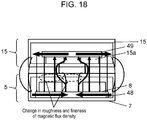
- FIG. 17 illustrates a state in which mobile terminal 15 is being charged in a state in which magnetic metal foreign object 52 (for example, an iron object) is present between the mobile terminal placement portion (the upper surface of support plate 6) and mobile terminal 15.
- magnetic metal foreign object 52 for example, an iron object
- This metal foreign object 52 is a magnetic body, and magnetic fluxes advancing into metal foreign object 52 include magnetic fluxes passing therethrough and magnetic fluxes advancing thereinto, for example, outward. Therefore, FIG. 17 illustrates the additional magnetic flux caused by the eddy current unlike FIG. 15 .
- the magnetic flux which is additionally generated in this way has a counterclockwise direction in FIG. 17 and thus has a direction opposite to the direction of the magnetic flux directed from charging coil 8 toward terminal charging coil 15a in an inner portion thereof (the central direction of charging coil 8).
- the magnetic flux has the same direction as the direction of the magnetic flux directed from charging coil 8 toward terminal charging coil 15a in an outer portion (a direction opposite to the center of charging coil 8) of the magnetic flux indicated by the counterclockwise arrow.
- a magnetic flux advancing in the inner peripheral direction of charging coil 8 is curved outward from the inner peripheral portion of charging coil 8 and is then directed toward terminal charging coil 15a (some magnetic fluxes advance into metal foreign object 52 in the outer circumference thereof).
- the magnetic flux in the inner peripheral portion of charging coil 8 decreases, and the magnetic flux in the outer peripheral portion of charging coil 8 increases.
- This situation can be detected by large diameter detection coil 43 and small diameter detection coil 44 disposed on the upper surface side (terminal charging coil 15a side) of charging coil 8.
- the first voltage (V1) detected by large diameter detection coil 43 increases (as a result of there being a large number of magnetic fluxes, and a distance to the magnetic fluxes also becoming short), and, conversely, the second voltage (V2) detected by small diameter detection coil 44 decreases (as a result of there being a small number of magnetic fluxes, and a distance to the magnetic fluxes also becoming long).
- Controller 10 compares the ratio (V2/V1) of the second voltage (V2) to the first voltage (V1) with a set value (which is stored in memory 47 and is, for example, 0.7), and performs a safety operation on the basis of a comparison result.
- the second voltage (V2) detected by small diameter detection coil 44 is, for example, 15% smaller than in the state (the absence of metal foreign object 52) illustrated in FIG. 14 .
- the first voltage (V1) detected by large diameter detection coil 43 is, for example, 170% larger than in the state (the absence of metal foreign object 52) illustrated in FIG. 14 .
- the ratio (V2/V1) of the second voltage (V2) to the first voltage (V1) is reduced by half or less (0.5 or less) in the state (the presence of metal foreign object 52) illustrated in FIG. 17 compared with the state (the absence of metal foreign object 52) illustrated in FIG. 14 .
- controller 10 Since the detected value (0.5 or less) is sufficiently smaller than the set value (0.7) stored in memory 47, controller 10 detects the presence of metal foreign object 52 so as to instantly stop the supply of a current to charging coil 8, and operates alarm 51 illustrated in FIGS. 2 and 9 .
- controller 10 lights alarm 51 so as to perform a notification of an abnormal state.
- the first voltage (V1) increases. If the inner magnetic flux decreases, the second voltage (V2) detected by small diameter detection coil 44 inversely decreases. Therefore, the ratio (V2/V1) between both voltages is sufficiently smaller than the set value, and, as result, it is possible to reliably detect the presence of metal foreign object 50 or 52 and to reliably perform a safety operation.
- An operation of detecting metal foreign object 50 or 52 (determination based on the ratio V2/V1) is not substantially influenced by whether the metal foreign object is a magnetic body or a nonmagnetic body, or the type of charged mobile terminal 15. Therefore, the mobile terminal charging device can charge various mobile terminals 15 with versatility and is considerably convenient to use.
- guard portion 53 protruding upward from support plate 6 is provided at the outer circumference of support plate 6.
- mobile terminal charging device 5 of the present exemplary embodiment in passenger compartment 2 of vehicle 1.
- intermediate diameter detection coil 54 switching between the detection coils 43, 44 and 54 for comparison can be performed, or situations between detection coils 43 and 54, and 54 and 44 can be detected.
- step S1 in FIG. 19 if power switch 40 illustrated in FIGS. 2 and 9 is turned on (step S1 in FIG. 19 ), a position of charging coil 8 is initialized (step S2 in FIG. 19 ).
- the position initialization indicates that charging coil 8 is returned to the corner (coordinates xo and yo) illustrated in FIG. 7 by driving motors 28 and 33.
- switches 41 and 42 are present at the corner, and, if charging coil 8 is moved to the corner inside main body case 7 provided with switches 41 and 42, switches 41 and 42 are operated, and thus controller 10 determines that a position of charging coil 8 has been initialized.
- controller 10 supplies detection pulses to the above-described eight foreign object detection coils 55 (L1, L2, L3, L4, L5, L6, L7, and L8), respectively.
- a resonance frequency of each of foreign object detection coils 55 is lower than a reference resonance frequency, held in memory 47, for each location where charging coil 8 is present, or in a case where a resonance voltage detected by each foreign object detection coil 55 is higher than a reference resonance voltage, held in memory 47, for each location where charging coil 8 is present, a safety operation is performed (steps S3 and S4 in FIG. 19 ).
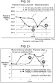
- FIG. 20 illustrates a state in which a resonance frequency of corresponding foreign object detection coil 55 is influenced by a location where charging coil 8 is present.
- line A of FIG. 20 indicates resonance frequencies of respective foreign object detection coils 55 (L1, L2, L3, L4, L5, L6, L7, and L8) when charging coil 8 is present at coordinates (10,0), and indicates a situation in which resonance frequencies of foreign object detection coils 55 (L8) near charging coil 8 are lowered.
- Line B of FIG. 20 indicates resonance frequencies of respective foreign object detection coils 55 (L1, L2, L3, L4, L5, L6, L7, and L8) when charging coil 8 is present at coordinates (10,35), and indicates a situation in which resonance frequencies of foreign object detection coils 55 (L5) near charging coil 8 are lowered.
- Line A of FIG. 21 indicates resonance voltages of respective foreign object detection coils 55 when charging coil 8 is present at coordinates (10,0), and indicates a situation in which a resonance voltage of foreign object detection coil 55 (L8) near charging coil 8 is heightened.
- Line B of FIG. 21 indicates resonance voltages of respective foreign object detection coils 55 when charging coil 8 is present at coordinates (10,35), and indicates a situation in which a resonance voltage of foreign object detection coil 55 (L5) near charging coil 8 is heightened.
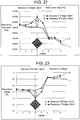
- Line A of FIG. 22 indicates resonance frequencies of respective foreign object detection coils 55 in a case where a metal foreign object is absent when charging coil 8 is present at coordinates (10,0).
- Line B of FIG. 22 indicates resonance frequencies of respective foreign object detection coils 55 in a case where a metal foreign object is present near fourth foreign object detection coil 55 when charging coil 8 is present at coordinates (10,0), and indicates a situation in which a resonance frequency of foreign object detection coil 55 (L4) near charging coil 8 is heightened.
- Line A of FIG. 23 indicates resonance voltages of respective foreign object detection coils 55 in a case where a metal foreign object is absent when charging coil 8 is present at coordinates (10,0).
- Line B of FIG. 23 indicates resonance voltages of respective foreign object detection coils 55 in a case where a metal foreign object is present at fourth foreign object detection coil 55 when charging coil 8 is present at coordinates (10,0), and indicates a situation in which a resonance voltage of foreign object detection coil 55 (L4) near charging coil 8 is lowered.
- a metal foreign object is detected by foreign object detection coils 55 during non-conduction of charging coil 8 (before conduction of charging coil 8) on the basis of such a phenomenon.
- memory 47 stores a reference resonance frequency and a reference resonance voltage of each foreign object detection coil 55 for each location where charging coil 8 is present.
- controller 10 detects a location where charging coil 8 is present by using position detection coil 14 (an example of a charging coil position detector), or switches 41 and 42 detecting that charging coil 8 has returned to the corner (coordinates xo and yo) illustrated in FIG. 7 .
- position detection coil 14 an example of a charging coil position detector
- switches 41 and 42 detecting that charging coil 8 has returned to the corner (coordinates xo and yo) illustrated in FIG. 7 .
- a metal foreign object is intended to be detected by foreign object detection coils 55 in a state of not being influenced by charging coil 8 during non-conduction of charging coil 8 (before conduction of charging coil 8).
- the safety operation during non-conduction of charging coil 8 is performed by alarm 51. And, there may be a configuration in which, if the metal foreign object is not removed thereafter, conduction of charging coil 8 cannot be performed.
- position detection coil 14 detects a location where mobile terminal 15 is placed (step S5 in FIG. 19 ).
- driver 9 moves charging coil 8 to the location (step S6 in FIG. 19 ).
- conduction of charging coil 8 is performed (step S7 in FIG. 19 ), and a foreign object detection operation is performed by large diameter detection coil 43 and small diameter detection coil 44 provided on the upper surface side of charging coil 8 (terminal charging coil 15a side) (step S8 in FIG. 19 ).
- controller 10 issues a warning with alarm 51 and stops charging using charging coil 8 as a safety operation (step S9 in FIG. 19 ).
- Next mobile terminal 15 may be subsequently placed on the upper surface of support plate 6 in a state in which charging is finished (step S10 in FIG. 19 ). Therefore, controller 10 stores a position of charging coil 8 in memory 47 (step S11 in FIG. 19 ), and finishes charging (step S12 in FIG. 19 ).
- controller 10 since it is important that a position of charging coil 8 be specified at this time in order to detect a foreign object, controller 10 stores the position of charging coil 8 in memory 47 (step S11 in FIG. 19 ) and finishes charging (step S12 in FIG. 19 ).
- controller 10 alternately repeatedly performs foreign object detection in foreign object detection coils 55 and position detection of charging coil 8 (at which location mobile terminal 15 is placed on the upper surface of support plate 6) in position detection coils 14 and switches 41 and 42.
- an operation is performed in which the foreign object detection coils 55 are subjected to division driving (L1 and L2 are driven), and thus it is detected whether or not there is a foreign object on the front surface side (upper surface side) of the front surface plate 11 during non-conduction of charging coil 8 (before conduction of charging coil 8), and then a plurality of position detection coils 14 (Y1 to Y6,..., and X1 to X3) are driven to detect a location where charging coil 8 is present.
- step S8 in FIG. 19 After the charging is started, foreign object detection on the upper surface of support plate 6 is performed by large diameter detection coil 43 and small diameter detection coil 44 provided on the upper surface side of charging coil 8 (terminal charging coil 15a side) as described above (step S8 in FIG. 19 ).
- foreign object detection before conduction of charging coil 8 can be simply performed so that a foreign object is detected by driving some of the plurality of foreign object detection coils 55, and, accordingly, it is possible to reduce time required to detect a foreign object before starting conduction. As a result, it is also possible to reduce time required to start charging using the charging coil, and thus the mobile terminal charging device is convenient to use.
- a foreign object after conduction of charging coil 8, a foreign object can be detected by large diameter detection coil 43 and small diameter detection coil 44 provided in charging coil 8.
- a foreign object before conduction for charging, a foreign object can be simply detected by driving some of the plurality of foreign object detection coils 55.
- it is possible to reduce time required to detect a foreign object before starting of conduction, and, accordingly, it is also possible to reduce time required to start charging of charging coil 8. As a result, convenience is improved.
- front surface plate 11 an example of a mobile terminal placement portion
- a distance from currently driven foreign object detection coils 55 for example, L3 and L4 to the foreign object is long. Therefore, there is a high probability that a foreign object may be detected even in this simple foreign object detection.
- the mobile terminal charging device of the present invention is convenient to use, and can reliably detect a foreign object and thus has high safety. Therefore, the mobile terminal charging device is expected as an on-vehicle charging device or a household charging device.
Abstract
Description
- The present invention relates to a mobile terminal charging device used to charge a mobile terminal such as a mobile phone, and a vehicle mounted with the same.
- Functions of a mobile terminal such as a mobile phone have been considerably advanced, and thus power consumption thereof has also been increased.
- Therefore, charging the mobile terminal is required to be performed at any locations including the inside of a vehicle. And, as a trend in recent years, a mobile terminal charging device which can perform so-called noncontact charging has attracted attention.
- In other words, the mobile terminal charging device includes a support plate whose surface side serves as a mobile terminal placement portion, and a charging coil provided to oppose a rear surface side of the support plate. If a mobile terminal is placed on the mobile terminal placement portion, the mobile terminal can be charged by using magnetic fluxes from the charging coil (for example, the following
PTLs -
- PTL 1: Japanese Patent Unexamined Publication No.
2012-16125 - PTL 2: Japanese Patent Unexamined Publication No.
2009-247194 - The present invention provides a mobile terminal charging device which is convenient to use.
- According to the present invention, there is provided a mobile terminal charging device including a support plate; a charging coil, a driver, a controller, and a memory. A front surface side the support plate is used as a mobile terminal placement portion. The charging coil is disposed to be movable in a state of opposing the support plate on a rear surface side of the support plate. The driver can move the charging coil on the rear surface side of the support plate. The controller is connected to the charging coil and the driver. The memory is connected to the controller. The support plate is provided with a plurality of foreign object detection coils and a plurality of position detection coils, and the charging coil is provided with a large diameter first detection coil, and a second detection coil disposed inside the first detection coil and having a smaller diameter than a diameter of the first detection coil. The plurality of foreign object detection coils, the plurality of position detection coils, and the first and second detection coils are connected to the controller. The memory stores a reference resonance frequency or a reference resonance voltage of each foreign object detection coil for each location where the charging coil is present. The controller alternately performs an operation of detecting a foreign object by driving some of the plurality of foreign object detection coils and then an operation of detecting a location where the charging coil is present by driving the plurality of position detection coils, in a state before conduction of the charging coil. The controller performs a safety operation when the plurality of foreign object detection coils detect a foreign object in a case where a resonance frequency detected by the foreign object detection coil corresponding to a location where the charging coil is present is higher than the reference resonance frequency stored in the memory, or a resonance voltage detected by the foreign object detection coil corresponding to a location where the charging coil is present is lower than the reference resonance voltage stored in the memory. The controller causes the charging coil to be conducted in a case where a location where the charging coil is present is detected by the plurality of position detection coils, and performs a safety operation if a ratio (V2/V1) of a second voltage (V2) detected by the second detection coil to a first voltage (V1) detected by the first detection coil is less than a set value after the charging coil is conducted.
- With this configuration, the mobile terminal charging device of the present invention is convenient to use.
- With the above-described configuration, it is possible to reliably detect a foreign object even in a case where mobile terminals of different models are charged. As a result, various types of mobile terminals can be charged, and thus convenience is improved.
- In the present invention, the controller alternately performs an operation of detecting a foreign object by driving some of the plurality of foreign object detection coils and then an operation of detecting a location where the charging coil is present by driving the plurality of position detection coils, in a state before conduction of the charging coil. Thus, in a case where a mobile terminal is placed on the mobile terminal placement portion, it is possible to start conduction of the charging coil within a shorter period of time. Also from this point, convenience is improved.
- After conduction of the charging coil, it is possible to detect a foreign object by using the large diameter first detection coil and the small diameter second detection coil provided in the charging coil. On the other hand, before conduction for charging, it is possible to simply detect a foreign object by driving some of the plurality of foreign object detection coils. Therefore, it is possible to reduce time required to detect a foreign object before starting conduction, and, accordingly, it is also possible to reduce time required to start charging using the charging coil. Also from this point, convenience is improved.
- Although a foreign object is simply detected by driving some of the plurality of foreign object detection coils, the mobile terminal placement portion is not so large, and thus a foreign object can be frequently detected unless a distance from currently driven foreign object detection coils to the foreign object is long. Therefore, there is a high probability that a foreign object may be detected even in this simple foreign object detection.
- Even if a foreign object cannot be detected according to the simple detection method, a foreign object can be reliably detected by using the above-described large diameter first detection coil and small diameter second detection coil provided in the charging coil after conduction. Thus, the safety is high.
-
-
FIG. 1 is a perspective view illustrating a state in which a mobile terminal charging device according to an exemplary embodiment of the present invention is provided inside a vehicle. -
FIG. 2 is a perspective view illustrating the mobile terminal charging device according to the exemplary embodiment of the present invention. -
FIG. 3 is a perspective view of the mobile terminal charging device illustrated inFIG. 2 . -
FIG. 4 is a perspective view illustrating a state in which a part of the mobile terminal charging device illustrated inFIG. 2 is omitted. -
FIG. 5 is a plan view illustrating the mobile terminal charging device in the state illustrated inFIG. 4 . -
FIG. 6 is a sectional view taken along a dashed line S-S' in the mobile terminal charging device illustrated inFIG. 2 . -
FIG. 7 is a perspective view illustrating another state of the mobile terminal charging device illustrated inFIG. 4 . -
FIG. 8 is a plan view illustrating the mobile terminal charging device in the state illustrated inFIG. 7 . -
FIG. 9 is a control block diagram of the mobile terminal charging device illustrated inFIG. 2 . -
FIG. 10 is a sectional view illustrating a configuration of a support plate of the mobile terminal charging device illustrated inFIG. 2 . -
FIG. 11 is a plan view illustrating a configuration of the support plate of the mobile terminal charging device illustrated inFIG. 2 . -
FIG. 12 is a perspective view illustrating a detection coil of the mobile terminal charging device illustrated inFIG. 2 . -
FIG. 13 is a plan view of the detection coil of the mobile terminal charging device illustrated inFIG. 2 . -
FIG. 14 is a diagram illustrating an operation of the mobile terminal charging device illustrated inFIG. 2 . -
FIG. 15 is a diagram illustrating an operation of the mobile terminal charging device illustrated inFIG. 2 . -
FIG. 16 is a diagram illustrating an operation of the mobile terminal charging device illustrated inFIG. 2 . -
FIG. 17 is a diagram illustrating an operation of the mobile terminal charging device illustrated inFIG. 2 . -
FIG. 18 is a diagram illustrating an operation of the mobile terminal charging device illustrated inFIG. 2 . -
FIG. 19 is a flowchart illustrating an operation of the mobile terminal charging device illustrated inFIG. 2 . -
FIG. 20 is a diagram illustrating a relationship between a location where a charging coil is present and a resonance frequency of a foreign object detection coil. -
FIG. 21 is a diagram illustrating a relationship between a location where the charging coil is present and a resonance voltage of the foreign object detection coil. -
FIG. 22 is a diagram illustrating a resonance frequency of the foreign object detection coil in a case where a metal foreign object is present. -
FIG. 23 is a diagram illustrating a resonance voltage of the foreign object detection coil in a case where a metal foreign object is present. -
FIG. 24 is a diagram illustrating an operation of the mobile terminal charging device illustrated inFIG. 2 . -
FIG. 25 is a diagram illustrating an operation of the mobile terminal charging device illustrated inFIG. 2 . - Prior to description of an exemplary embodiment of the present invention, problems of the above-described example of the related art will be described. In the example of the related art, in a case where, for example, a metal foreign object such as a coin is placed on the mobile terminal placement portion of the support plate, and a mobile terminal is further placed thereon, the metal foreign object is detected by foreign object detection means, and, for example, conduction of the charging coil is blocked.
- Therefore, it is possible to prevent the temperature of the foreign object from increasing due to magnetic fluxes from the charging coil.
- However, in the example of the related art, the foreign object detection means is formed of a plurality of metal detection antenna coils and an oscillation circuit connected to each of the metal detection antenna coils, and detects a foreign object by detecting an oscillation frequency of each metal detection antenna coil. Thus, the foreign object detection means is not preferable in terms of versatility.
- In other words, in the example of the related art, if there is a metal foreign object, the foreign object is detected by using a change in an oscillation state of the oscillation circuit. In such a configuration, the oscillation circuit is extremely delicately set, and thus the configuration is useful for charging a mobile terminal whose characteristics are known in advance. However, in a case where a mobile terminal whose characteristics are not known is charged, an oscillation state is changed by the mobile terminal, and, as a result, there is a mobile terminal which cannot be charged, and thus the configuration is not preferable in terms of versatility.
- For example, in a case where the mobile terminal charging device is provided in a passenger compartment of a vehicle an unspecified large number of people frequently try to charge various types of mobile terminals. In this state, mobile terminals cannot be charged depending on models of the mobile terminals, and thus the mobile terminal charging device is inconvenient.
- In this example of the related art, a foreign object is detected in the entire region of the mobile terminal placement portion by the foreign object detection means using a plurality of metal detection antenna coils, and the charging coil is conducted. Therefore, in foreign object detection using the metal detection antenna coil, an oscillation state change of the oscillation circuit is detected. Thus, it takes a long time for each metal detection antenna coil to perform detection. In other words, the charging coil cannot be conducted unless a foreign object can be detected by using all of the metal detection antenna coils. Therefore, it takes a long time for the charging coil to start charging. Also for this reason, the mobile terminal charging device is inconvenient.
- Hereinafter, with reference to the accompanying drawings, a description will be made of an example in which a mobile terminal charging device according to an exemplary embodiment of the present invention is equipped in a vehicle.
- In
FIG. 1 ,steering wheel 3 is provided on the front side inpassenger compartment 2 ofvehicle 1. -
Electronic apparatus 4 which reproduces music or videos and displays car navigation images and the like is provided on the lateral side ofsteering wheel 3. - Mobile
terminal charging device 5 is provided on the rear side ofelectronic apparatus 4 inpassenger compartment 2. - Mobile
terminal charging device 5 includes, as illustrated inFIGS. 2 to 8 , box-shapedmain body case 7 in whichsupport plate 6 is disposed on an upper surface thereof; chargingcoil 8 provided to be movable in a horizontal direction in a state of opposing a lower surface side ofsupport plate 6 in themain body case 7;driver 9 which causes chargingcoil 8 to be moved in the horizontal direction so as to oppose the lower surface side ofsupport plate 6; and a controller (thereference numeral 10 inFIG. 9 ) connected todriver 9 and chargingcoil 8. - Hereinafter, each constituent element will be described in detail.
- First,
support plate 6 will be described. - As illustrated in
FIG. 6 ,support plate 6 has a configuration in whichfront surface plate 11,intermediate plate 12, andrear surface plate 13 overlap each other. -
Front surface plate 11 andrear surface plate 13 are made of synthetic resin, andintermediate plate 12 is made of ceramics. In other words, a magnetic flux from chargingcoil 8 can pass throughsupport plate 6 towardmobile terminal 15. - Position detection coils 14 (an example of a charging coil position detector) illustrated in
FIGS. 10 and 11 are provided in the Y direction and the X direction on front and rear surfaces ofintermediate plate 12. Position detection coils 14 are provided in a state in which ten or more position detection coils (Y1, Y2, Y3, Y4, Y5, Y6,...) extending in the Y direction and three position detection coils (X1, X2, and X3) extending in the X direction, as understood fromFIG. 11 , intersect each other with a predetermined gap in the Y direction and the X direction on the upper and lower sides ofintermediate plate 12 ofsupport plate 6, as understood fromFIG. 10 . - Position detection coils 14 are also used in, for example,
PTL 2, and detects at which positionmobile terminal 15 is placed on the mobile terminal placement portion which is the upper surface ofsupport plate 6 as illustrated inFIG. 3 . - In the present exemplary embodiment, position detection coils 14 detect at which position
mobile terminal 15 is placed on the upper surface ofsupport plate 6 as illustrated inFIG. 3 . Next,driver 9moves charging coil 8 to a position opposing a terminal charging coil (thereference numeral 15a inFIG. 14 ) ofmobile terminal 15, and then conduction of chargingcoil 8 is performed. - As understood from
FIGS. 10 and 11 , four foreign object detection coils 55 (L1, L2, L3, and L4) extending in the Y direction are disposed in a state of being close to each other on a front surface side (upper surface side) offront surface plate 11. Four foreign object detection coils 55 (L5, L6, L7, and L8) are further disposed in a state of being close to each other in the Y direction on a rear surface side (lower surface side) ofrear surface plate 13. - In the present exemplary embodiment, it is detected whether or not there is a foreign object on the front surface (upper surface side) of
front surface plate 11 during non-conduction of charging coil 8 (before conduction of charging coil 8), by subjecting foreign object detection coils 55 to division driving (L1 and L2 are driven, L3 and L4 are driven, L5 and L6 are driven, and L7 and L8 are driven). This will be described in detail in the following description of an operation thereof. - Next, charging
coil 8 will be described. - As illustrated in
FIGS. 4 and5 , chargingcoil 8 has a ring shape formed by winding a wiring material in a spiral shape. An outer peripheral side and a lower surface side of the charging coil are held in a state of being covered with holdingmember 16 made of synthetic resin. -
Support leg 17 extending toward a lower side of chargingcoil 8 is integrally formed with holdingmember 16 on its lower surface by using synthetic resin as illustrated inFIG. 6 . - A gap of 0.3 millimeters is provided between a lower surface of
support leg 17 and an upper surface ofmetallic support plate 18 disposed undersupport leg 17. Therefore, in a normal state, the lower surface ofsupport leg 17 is not in contact with the upper surface ofsupport plate 18 during movement of chargingcoil 8. -
Control board 19 and alower plate 20 ofmain body case 7 are disposed undersupport plate 18.Support member 21 penetrating throughcontrol board 19 is provided between a lower surface ofsupport plate 18 and an upper surface oflower plate 20. In other words, in the present exemplary embodiment, the lower surface side ofsupport plate 18 is supported bylower plate 20 ofmain body case 7 viasupport member 21 in order to increase the strength relative to excessive weight. - Next,
driver 9 will be described. - As illustrated in
FIGS. 4 and5 ,driver 9 includes X-axisdirection driving shaft 22 and Y-axisdirection driving shaft 23. An intermediate portion of each of X-axisdirection driving shaft 22 and Y-axisdirection driving shaft 23 is engaged with holdingmember 16 in portions other than a portion of holding the chargingcoil holding member 16. - In other words, a penetration hole (not illustrated) through which X-axis
direction driving shaft 22 penetrates andpenetration hole 24 through which Y-axisdirection driving shaft 23 penetrates are provided in holdingmember 16 with a predetermined gap in the vertical direction in a state of crossing each other. X-axisdirection driving shaft 22 and Y-axisdirection driving shaft 23 penetrate through the penetration hole so as to be engaged with each other. -
Worm wheel 25 is provided at one end side of X-axisdirection driving shaft 22,gear 26 is provided at one end side thereof, andgear 26 is also provided at the other end side thereof. -
Worm wheel 25 is engaged withworm 27, andworm 27 is connected tomotor 28. -
Gears 26 on both sides are respectively engaged withgear plates 29. - Therefore, if
motor 28 is driven,worm 27 is rotated, and thusworm wheel 25 is moved in the X axis direction along with X-axisdirection driving shaft 22. Therefore, chargingcoil 8 is moved in the X axis direction. -
Worm wheel 30 is provided at one end side of Y-axisdirection driving shaft 23,gear 31 is provided at one end side thereof, andgear 31 is also provided at the other end side thereof. -
Worm wheel 30 is engaged withworm 32, andworm 32 is connected tomotor 33. -
Gears 31 on both sides are respectively engaged withgear plates 34. - Therefore, if
motor 33 is driven,worm 32 is rotated, and thusworm wheel 30 is moved in the Y axis direction along with Y-axisdirection driving shaft 23. Therefore, chargingcoil 8 is moved in the Y axis direction. - The
reference numeral 35 illustrated inFIG. 4 indicates a flexible wiring causing a current to flow through chargingcoil 8, and an end offlexible wiring 35 is fixed to the side surface of above-describedsupport leg 17. - As illustrated in
FIG. 9 ,controller 10 is connected tomotor 28 viaX-axis motor controller 36, and is connected tomotor 33 via Y-axis motor controller 37. -
Controller 10 is connected to chargingcoil 8 via chargingcoil controller 38, and is also connected to position detection coils 14 via positiondetection coil controller 39. - Next, a description will be made of a configuration of detecting whether or not there is a foreign object on the front surface side (upper surface side) of
front surface plate 11 during conduction of chargingcoil 8. - In the present exemplary embodiment, as described above, foreign object detection coils 55 detect whether or not there is a foreign object on the front surface side (upper surface side) of
front surface plate 11 during non-conduction of charging coil 8 (before conduction of charging coil 8). On the other hand, during conduction of charging coil 8 (after conduction of charging coil 8), the presence of a foreign object is detected by largediameter detection coil 43 illustrated inFIGS. 12 and 13 provided between chargingcoil 8 and the mobile terminal placement portion ofsupport plate 6, anddetection coil 44 which is disposed insidedetection coil 43.Detection coil 44 has a smaller diameter than that ofdetection coil 43. - Specifically, since charging
coil 8 is movable depending on a location wheremobile terminal 15 is placed, detection coils 43 and 44 are disposed on the upper surface of charging coil 8 (the surface onsupport plate 6 side), and are moved along with chargingcoil 8. - Large
diameter detection coil 43 has nearly the same size as the outer diameter of annular charging coil 8 (the detection coil is slightly smaller than the outer diameter of charging coil 8), and smalldiameter detection coil 44 has nearly the same size as the inner diameter of annular charging coil 8 (the detection coil is slightly larger than the inner diameter of charging coil 8). - As illustrated in
FIG. 9 , largediameter detection coil 43 and smalldiameter detection coil 44 are connected tocontroller 10 viavoltage detectors - The
reference numeral 47 illustrated inFIG. 9 indicates a memory which stores a program or the like for performing a safety operation on metal foreign objects by using largediameter detection coil 43 and smalldiameter detection coil 44. - In the present exemplary embodiment, if a metal foreign object is present between the mobile terminal placement portion (the upper surface of support plate 6) and
mobile terminal 15, it is found that a magnetic flux in the inner portion of chargingcoil 8 decreases, and, conversely, a magnetic flux in the outer portion increases, and this state is detected by largediameter detection coil 43 and smalldiameter detection coil 44. - Hereinafter, this state will be described with reference to
FIGS. 13 to 18 simplified for better understanding. -
FIG. 14 illustrates a state in whichmobile terminal 15 is being charged (during conduction of charging coil 8) in a state in which there is no metal foreign object between the mobile terminal placement portion (the upper surface of support plate 6) and mobile terminal 15 as inFIG. 3 . - In
FIGS. 13 to 18 , thereference numeral 48 indicates a magnetic body for forming a magnetic path, provided on a lower side (an opposite side to mobile terminal 15) of chargingcoil 8 inmain body case 7 of mobileterminal charging device 5. Thereference numeral 49 indicates a magnetic body for forming a magnetic path, provided on an upper side (an opposite side to mobile terminal charging device 5) ofterminal charging coil 15a inmobile terminal 15. - If a charging operation is performed, as illustrated in
FIG. 14 , a magnetic flux from chargingcoil 8 of mobileterminal charging device 5 is supplied toterminal charging coil 15a ofmobile terminal 15. This magnetic flux induces a voltage interminal charging coil 15a, and thusmobile terminal 15 is charged by the voltage. - The magnetic flux having passed through
terminal charging coil 15a returns to chargingcoil 8 viamagnetic body 49, a space, andmagnetic body 48 as indicated by arrows. - In contrast,
FIG. 15 illustrates a state in whichmobile terminal 15 is being charged in a state in which non-magnetic metal foreign object 50 (for example, a coin made of aluminum) is present between the mobile terminal placement portion (the upper surface of support plate 6) andmobile terminal 15. - In this case, as illustrated in
FIG. 15 , an eddy current is induced in metalforeign object 50 by a magnetic flux passing through metalforeign object 50. As a result, a magnetic flux is generated as indicated by a counterclockwise arrow inFIG. 15 . - The magnetic flux indicated by the counterclockwise arrow has a direction opposite to a direction of a magnetic flux directed from charging
coil 8 towardterminal charging coil 15a in an inner portion of metal foreign object (the central direction of charging coil 8). The magnetic flux indicated by the counterclockwise arrow has the same direction as the direction of the magnetic flux directed from chargingcoil 8 towardterminal charging coil 15a in an outer portion (a direction opposite to the center of charging coil 8). - As a result, as illustrated in
FIG. 16 , among the magnetic fluxes directed from chargingcoil 8 towardterminal charging coil 15a, a magnetic flux advancing in the inner peripheral direction of chargingcoil 8 is curved outward from the inner peripheral portion of chargingcoil 8 and is then directed towardterminal charging coil 15a. - In other words, the magnetic flux in the inner peripheral portion of charging
coil 8 decreases, and, conversely, the magnetic flux in the outer peripheral portion of chargingcoil 8 increases. - In this situation, in the present exemplary embodiment, since large
diameter detection coil 43 is provided on the upper surface side (terminal charging coil 15a side) of chargingcoil 8 and smalldiameter detection coil 44 is provided insidedetection coil 43 as described above, a state illustrated inFIG. 16 can be detected bydetection coils - Specifically, a first voltage (V1) detected by large
diameter detection coil 43 increases (as a result of there being a large number of magnetic fluxes, and a distance to the magnetic fluxes also becoming short). Conversely, a second voltage (V2) detected by smalldiameter detection coil 44 decreases (as a result of there being a small number of magnetic fluxes, and a distance to the magnetic fluxes also becoming long). - In the present exemplary embodiment,
voltage detector 45 detects a peak voltage of the first voltage (V1) detected by largediameter detection coil 43.Voltage detector 46 detects a peak voltage of the second voltage (V2) detected by smalldiameter detection coil 44. -
Controller 10 compares the ratio (V2/V1) of the second voltage (V2) to the first voltage (V1) with a set value (which is stored inmemory 47 and is, for example, 0.7), and performs a safety operation on the basis of a comparison result. - As an example, in the state (the presence of metal foreign object 50) illustrated in
FIG. 16 , the second voltage (V2) detected by smalldiameter detection coil 44 is, for example, 25% smaller than in the state (the absence of metal foreign object 50) illustrated inFIG. 13 . - In contrast, in the state (the presence of metal foreign object 50) illustrated in
FIG. 16 , the first voltage (V1) detected by largediameter detection coil 43 is, for example, 170% larger than in the state (the absence of metal foreign object 50) illustrated inFIG. 13 . - As a result, the ratio (V2/V1) of the second voltage (V2) to the first voltage (V1) is reduced by half or less (0.5 or less) in the state (the presence of metal foreign object 50) illustrated in
FIG. 16 compared with the state (the absence of metal foreign object 50) illustrated inFIG. 14 . - Since the detected value (0.5 or less) is sufficiently smaller than the set value (0.7) stored in
memory 47,controller 10 detects the presence of metalforeign object 50 so as to instantly stop the supply of a current to chargingcoil 8, and operatesalarm 51 illustrated inFIGS. 2 and9 . - In other words,
alarm 51 is connected tocontroller 10 as illustrated inFIG. 9 , and thus performs a notification of an abnormal state with a light when metalforeign object 50 is present. - Next,
FIG. 17 illustrates a state in whichmobile terminal 15 is being charged in a state in which magnetic metal foreign object 52 (for example, an iron object) is present between the mobile terminal placement portion (the upper surface of support plate 6) andmobile terminal 15. - Also in this case, as illustrated in
FIG. 17 , an eddy current is induced in metalforeign object 52 by a magnetic flux passing through metalforeign object 52. As a result, a magnetic flux is generated as indicated by a counterclockwise arrow inFIG. 16 . - This metal
foreign object 52 is a magnetic body, and magnetic fluxes advancing into metalforeign object 52 include magnetic fluxes passing therethrough and magnetic fluxes advancing thereinto, for example, outward. Therefore,FIG. 17 illustrates the additional magnetic flux caused by the eddy current unlikeFIG. 15 . - However, the magnetic flux which is additionally generated in this way has a counterclockwise direction in
FIG. 17 and thus has a direction opposite to the direction of the magnetic flux directed from chargingcoil 8 towardterminal charging coil 15a in an inner portion thereof (the central direction of charging coil 8). The magnetic flux has the same direction as the direction of the magnetic flux directed from chargingcoil 8 towardterminal charging coil 15a in an outer portion (a direction opposite to the center of charging coil 8) of the magnetic flux indicated by the counterclockwise arrow. - As a result, as illustrated in
FIG. 18 , among the magnetic fluxes directed from chargingcoil 8 towardterminal charging coil 15a, a magnetic flux advancing in the inner peripheral direction of chargingcoil 8 is curved outward from the inner peripheral portion of chargingcoil 8 and is then directed towardterminal charging coil 15a (some magnetic fluxes advance into metalforeign object 52 in the outer circumference thereof). - In other words, the magnetic flux in the inner peripheral portion of charging
coil 8 decreases, and the magnetic flux in the outer peripheral portion of chargingcoil 8 increases. - This situation can be detected by large
diameter detection coil 43 and smalldiameter detection coil 44 disposed on the upper surface side (terminal charging coil 15a side) of chargingcoil 8. - Specifically, the first voltage (V1) detected by large
diameter detection coil 43 increases (as a result of there being a large number of magnetic fluxes, and a distance to the magnetic fluxes also becoming short), and, conversely, the second voltage (V2) detected by smalldiameter detection coil 44 decreases (as a result of there being a small number of magnetic fluxes, and a distance to the magnetic fluxes also becoming long). - A peak voltage of the first voltage (V1) detected by large
diameter detection coil 43 is detected byvoltage detector 45. A peak voltage of the second voltage (V2) detected by smalldiameter detection coil 44 is detected byvoltage detector 46.Controller 10 compares the ratio (V2/V1) of the second voltage (V2) to the first voltage (V1) with a set value (which is stored inmemory 47 and is, for example, 0.7), and performs a safety operation on the basis of a comparison result. - As an example, in the state (the presence of metal foreign object 52) illustrated in
FIG. 17 , the second voltage (V2) detected by smalldiameter detection coil 44 is, for example, 15% smaller than in the state (the absence of metal foreign object 52) illustrated inFIG. 14 . - In contrast, in the state (the presence of metal foreign object 52) illustrated in
FIG. 17 , the first voltage (V1) detected by largediameter detection coil 43 is, for example, 170% larger than in the state (the absence of metal foreign object 52) illustrated inFIG. 14 . - As a result, the ratio (V2/V1) of the second voltage (V2) to the first voltage (V1) is reduced by half or less (0.5 or less) in the state (the presence of metal foreign object 52) illustrated in
FIG. 17 compared with the state (the absence of metal foreign object 52) illustrated inFIG. 14 . - Since the detected value (0.5 or less) is sufficiently smaller than the set value (0.7) stored in
memory 47,controller 10 detects the presence of metalforeign object 52 so as to instantly stop the supply of a current to chargingcoil 8, and operatesalarm 51 illustrated inFIGS. 2 and9 . - In other words,
controller 10lights alarm 51 so as to perform a notification of an abnormal state. - As described above, in the present exemplary embodiment, even if either of nonmagnetic metal
foreign object 50 and magnetic metalforeign object 52 is present between mobile terminal placement portion (the upper surface of support plate 6) andmobile terminal 15, it is found that a magnetic flux in the inner portion of chargingcoil 8 decreases, and, conversely, magnetic fluxes in other portions increase, and this state is detected by largediameter detection coil 43 and smalldiameter detection coil 44. - In other words, in a case where large
diameter detection coil 43 detects an increase in the outer magnetic flux, the first voltage (V1) increases. If the inner magnetic flux decreases, the second voltage (V2) detected by smalldiameter detection coil 44 inversely decreases. Therefore, the ratio (V2/V1) between both voltages is sufficiently smaller than the set value, and, as result, it is possible to reliably detect the presence of metalforeign object - An operation of detecting metal
foreign object 50 or 52 (determination based on the ratio V2/V1) is not substantially influenced by whether the metal foreign object is a magnetic body or a nonmagnetic body, or the type of chargedmobile terminal 15. Therefore, the mobile terminal charging device can charge variousmobile terminals 15 with versatility and is considerably convenient to use. - In the present exemplary embodiment, a description has been made of an example in which mobile
terminal charging device 5 is provided inpassenger compartment 2 ofvehicle 1. - This is because a coin or the like is frequently placed on
support plate 6 invehicle 1. - In other words, in
vehicle 1,mobile terminal 15 is deviated from the upper surface ofsupport plate 6 due to inertia of an advancing direction or vibration during driving of the vehicle. Thus, as a countermeasure therefor, as illustrated inFIG. 3 ,guard portion 53 protruding upward fromsupport plate 6 is provided at the outer circumference ofsupport plate 6. - As a result, a state occurs in which a coin hardly falls off during driving of the vehicle, and this causes the coin to be placed on
support plate 6. - Therefore, it is very useful to provide mobile
terminal charging device 5 of the present exemplary embodiment inpassenger compartment 2 ofvehicle 1. - In the present exemplary embodiment, a description has been made of an example in which large
diameter detection coil 43 and smalldiameter detection coil 44 are provided on the upper surface side of charging coil 8 (terminal charging coil 15a side). And, as illustrated inFIGS. 12 and 13 , there may be a configuration in which intermediatediameter detection coil 54 is provided between largediameter detection coil 43 and smalldiameter detection coil 44 and is also connected tocontroller 10. - In other words, if intermediate
diameter detection coil 54 is provided, switching between the detection coils 43, 44 and 54 for comparison can be performed, or situations between detection coils 43 and 54, and 54 and 44 can be detected. - In the above-described configuration, if
power switch 40 illustrated inFIGS. 2 and9 is turned on (step S1 inFIG. 19 ), a position of chargingcoil 8 is initialized (step S2 inFIG. 19 ). - The position initialization indicates that charging
coil 8 is returned to the corner (coordinates xo and yo) illustrated inFIG. 7 by drivingmotors - In other words, switches 41 and 42 are present at the corner, and, if charging
coil 8 is moved to the corner insidemain body case 7 provided withswitches controller 10 determines that a position of chargingcoil 8 has been initialized. - Next,
controller 10 supplies detection pulses to the above-described eight foreign object detection coils 55 (L1, L2, L3, L4, L5, L6, L7, and L8), respectively. In a case where a resonance frequency of each of foreign object detection coils 55 is lower than a reference resonance frequency, held inmemory 47, for each location where chargingcoil 8 is present, or in a case where a resonance voltage detected by each foreignobject detection coil 55 is higher than a reference resonance voltage, held inmemory 47, for each location where chargingcoil 8 is present, a safety operation is performed (steps S3 and S4 inFIG. 19 ). - In relation to detailed description thereof,
FIG. 20 illustrates a state in which a resonance frequency of corresponding foreignobject detection coil 55 is influenced by a location where chargingcoil 8 is present. - Specifically, line A of
FIG. 20 indicates resonance frequencies of respective foreign object detection coils 55 (L1, L2, L3, L4, L5, L6, L7, and L8) when chargingcoil 8 is present at coordinates (10,0), and indicates a situation in which resonance frequencies of foreign object detection coils 55 (L8) near chargingcoil 8 are lowered. - Line B of
FIG. 20 indicates resonance frequencies of respective foreign object detection coils 55 (L1, L2, L3, L4, L5, L6, L7, and L8) when chargingcoil 8 is present at coordinates (10,35), and indicates a situation in which resonance frequencies of foreign object detection coils 55 (L5) near chargingcoil 8 are lowered. - Line A of
FIG. 21 indicates resonance voltages of respective foreign object detection coils 55 when chargingcoil 8 is present at coordinates (10,0), and indicates a situation in which a resonance voltage of foreign object detection coil 55 (L8) near chargingcoil 8 is heightened. - Line B of
FIG. 21 indicates resonance voltages of respective foreign object detection coils 55 when chargingcoil 8 is present at coordinates (10,35), and indicates a situation in which a resonance voltage of foreign object detection coil 55 (L5) near chargingcoil 8 is heightened. - In other words, it has been found that a resonance frequency of foreign
object detection coil 55 near chargingcoil 8 is lowered, and, conversely, a resonance voltage of foreignobject detection coil 55 near chargingcoil 8 is heightened. - Line A of
FIG. 22 indicates resonance frequencies of respective foreign object detection coils 55 in a case where a metal foreign object is absent when chargingcoil 8 is present at coordinates (10,0). - Line B of
FIG. 22 indicates resonance frequencies of respective foreign object detection coils 55 in a case where a metal foreign object is present near fourth foreignobject detection coil 55 when chargingcoil 8 is present at coordinates (10,0), and indicates a situation in which a resonance frequency of foreign object detection coil 55 (L4) near chargingcoil 8 is heightened. - Line A of
FIG. 23 indicates resonance voltages of respective foreign object detection coils 55 in a case where a metal foreign object is absent when chargingcoil 8 is present at coordinates (10,0). - Line B of
FIG. 23 indicates resonance voltages of respective foreign object detection coils 55 in a case where a metal foreign object is present at fourth foreignobject detection coil 55 when chargingcoil 8 is present at coordinates (10,0), and indicates a situation in which a resonance voltage of foreign object detection coil 55 (L4) near chargingcoil 8 is lowered. - In other words, it has been found that a resonance frequency of foreign
object detection coil 55 near the metal foreign object is heightened, and, conversely, a resonance voltage of foreignobject detection coil 55 near the metal foreign object is lowered. - In the present exemplary embodiment, a metal foreign object is detected by foreign object detection coils 55 during non-conduction of charging coil 8 (before conduction of charging coil 8) on the basis of such a phenomenon.
- Specifically,
memory 47 stores a reference resonance frequency and a reference resonance voltage of each foreignobject detection coil 55 for each location where chargingcoil 8 is present. - In this state, first,
controller 10 detects a location where chargingcoil 8 is present by using position detection coil 14 (an example of a charging coil position detector), or switches 41 and 42 detecting that chargingcoil 8 has returned to the corner (coordinates xo and yo) illustrated inFIG. 7 . - In other words, a metal foreign object is intended to be detected by foreign object detection coils 55 in a state of not being influenced by charging
coil 8 during non-conduction of charging coil 8 (before conduction of charging coil 8). - In the present exemplary embodiment, as illustrated in
FIG. 24 , in a state in whichpower switch 40 is turned on, during non-conduction of chargingcoil 8, foreign object detection performed by foreign object detection coils 55 and position detection of chargingcoil 8 performed by position detection coils 14 and switches 41 and 42 are alternately repeatedly performed. - As illustrated in
FIGS. 22 and 23 , for example, if resonance frequencies detected by eight foreign object detection coils 55 are higher than the resonance frequencies stored inmemory 47 in advance by a predetermined value or more, or resonance voltages detected by eight foreign object detection coils 55 are lower than the resonance voltages stored inmemory 47 in advance by a predetermined value or more through the operation, the presence of a foreign object is recognized, and a safety operation is performed (steps S3 and S4 inFIG. 19 ). - The safety operation during non-conduction of charging
coil 8 is performed byalarm 51. And, there may be a configuration in which, if the metal foreign object is not removed thereafter, conduction of chargingcoil 8 cannot be performed. - Next, in a case where
mobile terminal 15 is placed at any position of the mobile terminal placement portion which is the upper surface ofsupport plate 6 as illustrated inFIG. 3 ,position detection coil 14 detects a location wheremobile terminal 15 is placed (step S5 inFIG. 19 ). Next,driver 9moves charging coil 8 to the location (step S6 inFIG. 19 ). Next, conduction of chargingcoil 8 is performed (step S7 inFIG. 19 ), and a foreign object detection operation is performed by largediameter detection coil 43 and smalldiameter detection coil 44 provided on the upper surface side of charging coil 8 (terminal charging coil 15a side) (step S8 inFIG. 19 ). - If a metal foreign object is detected during charging,
controller 10 issues a warning withalarm 51 and stops charging using chargingcoil 8 as a safety operation (step S9 inFIG. 19 ). - Next
mobile terminal 15 may be subsequently placed on the upper surface ofsupport plate 6 in a state in which charging is finished (step S10 inFIG. 19 ). Therefore,controller 10 stores a position of chargingcoil 8 in memory 47 (step S11 inFIG. 19 ), and finishes charging (step S12 inFIG. 19 ). - In other words, since a current does not flow to charging
coil 8 in this state, in a charging stop state after the charging as illustrated inFIG. 24 , foreign object detection performed by foreign object detection coils 55 and position detection of chargingcoil 8 performed by position detection coils 14 and switches 41 and 42 are alternately repeatedly performed. - As is clear from the above description, since it is important that a position of charging
coil 8 be specified at this time in order to detect a foreign object,controller 10 stores the position of chargingcoil 8 in memory 47 (step S11 inFIG. 19 ) and finishes charging (step S12 inFIG. 19 ). - In other words, since resonance frequencies or resonance voltages of eight foreign object detection coils 55 are influenced by a position of charging
coil 8, information corresponding to the position of chargingcoil 8 is read frommemory 47, and appropriate foreign object detection is performed on the basis of the read information. - Next, other features of the present exemplary embodiment will be described.
- In the present exemplary embodiment, as described above, a state before conduction of charging
coil 8,controller 10 alternately repeatedly performs foreign object detection in foreign object detection coils 55 and position detection of charging coil 8 (at which location mobile terminal 15 is placed on the upper surface of support plate 6) in position detection coils 14 and switches 41 and 42. - As an example of the features, there is a configuration in which, regarding driving of position detection coils 14, as understood from
FIG. 25 , an operation of detecting a foreign object by driving some of the plurality of foreign object detection coils 55 (L1, L2, L3, L4, L5, L6, L7, and L8) and an operation of detecting a location where chargingcoil 8 is present by driving the plurality of position detection coils 14 (Y1 to X3) are alternately performed. - Specifically, an operation is performed in which the foreign object detection coils 55 are subjected to division driving (L1 and L2 are driven), and thus it is detected whether or not there is a foreign object on the front surface side (upper surface side) of the
front surface plate 11 during non-conduction of charging coil 8 (before conduction of charging coil 8), and then a plurality of position detection coils 14 (Y1 to Y6,..., and X1 to X3) are driven to detect a location where chargingcoil 8 is present. - Next, an operation is performed in which the foreign object detection coils 55 are subjected to division driving (L3 and L4 are driven), and thus it is detected whether or not there is a foreign object on the front surface side (upper surface side) of the
front surface plate 11 during non-conduction of charging coil 8 (before conduction of charging coil 8), and then the plurality of position detection coils 14 (Y1 to Y6,..., and X1 to X3) are driven to detect a location where chargingcoil 8 is present. - Next, an operation is performed in which the foreign object detection coils 55 are subjected to division driving (L5 and L6 are driven), and thus it is detected whether or not there is a foreign object on the front surface side (upper surface side) of the
front surface plate 11 during non-conduction of charging coil 8 (before conduction of charging coil 8), and then the plurality of position detection coils 14 (Y1 to Y6,..., and X1 to X3) are driven to detect a location where chargingcoil 8 is present. - Next, an operation is performed in which the foreign object detection coils 55 are subjected to division driving (L7 and L8 are driven), and thus it is detected whether or not there is a foreign object on the front surface side (upper surface side) of the
front surface plate 11 during non-conduction of charging coil 8 (before conduction of charging coil 8), and then the plurality of position detection coils 14 (Y1 to Y6,..., and X1 to X3) are driven to detect a location where chargingcoil 8 is present. - These operations are repeatedly performed until
mobile terminal 15 is placed on the upper surface ofsupport plate 6. - Here, if
mobile terminal 15 is placed on the upper surface ofsupport plate 6, a position ofmobile terminal 15 is detected by the plurality of position detection coils 14 (Y1 to Y6,..., and X1 to X3) at that time, chargingcoil 8 is moved to a position opposing the position of the mobile terminal, and thus charging is started. - After the charging is started, foreign object detection on the upper surface of
support plate 6 is performed by largediameter detection coil 43 and smalldiameter detection coil 44 provided on the upper surface side of charging coil 8 (terminal charging coil 15a side) as described above (step S8 inFIG. 19 ). - In the present embodiment, as mentioned above, foreign object detection before conduction of charging
coil 8 can be simply performed so that a foreign object is detected by driving some of the plurality of foreign object detection coils 55, and, accordingly, it is possible to reduce time required to detect a foreign object before starting conduction. As a result, it is also possible to reduce time required to start charging using the charging coil, and thus the mobile terminal charging device is convenient to use. - In other words, in the present embodiment, after conduction of charging
coil 8, a foreign object can be detected by largediameter detection coil 43 and smalldiameter detection coil 44 provided in chargingcoil 8. On the other hand, before conduction for charging, a foreign object can be simply detected by driving some of the plurality of foreign object detection coils 55. Thus, it is possible to reduce time required to detect a foreign object before starting of conduction, and, accordingly, it is also possible to reduce time required to start charging of chargingcoil 8. As a result, convenience is improved. - When this is described a little more, in foreign object detection using foreign object detection coils 55, detection is performed on the basis of a resonance frequency or a resonance voltage, this detection is required to be determined after a plurality of waveforms are detected, and thus time for the detection is increased.
- In contrast, in the operation of detecting a location where charging
coil 8 is present by driving a plurality of position detection coils 14 (Y1 to Y6,..., and X1 to X3), determination can be performed on the basis of information regarding a single pulse, and thus time for detection can be reduced. - Even in a simple type operation of detecting a foreign object by driving some of the plurality of foreign object detection coils 55, front surface plate 11 (an example of a mobile terminal placement portion) is not so large, and thus a foreign object can be frequently detected unless a distance from currently driven foreign object detection coils 55 (for example, L3 and L4) to the foreign object is long. Therefore, there is a high probability that a foreign object may be detected even in this simple foreign object detection.
- As mentioned above, the mobile terminal charging device of the present invention is convenient to use, and can reliably detect a foreign object and thus has high safety. Therefore, the mobile terminal charging device is expected as an on-vehicle charging device or a household charging device.
-
- 1
- vehicle
- 2
- passenger compartment
- 3
- steering wheel
- 4
- electronic apparatus
- 5
- mobile terminal charging device
- 6
- support plate
- 7
- main body case
- 8
- charging coil
- 9
- driver
- 10
- controller
- 11
- front surface plate
- 12
- intermediate plate
- 13
- rear surface plate
- 14
- position detection coil
- 15
- mobile terminal
- 15a
- terminal charging coil
- 16
- holding member
- 17
- support leg
- 18
- support plate
- 19
- control board
- 20
- lower plate
- 21
- support member
- 22
- X-axis direction driving shaft
- 23
- Y-axis direction driving shaft
- 24
- penetration hole
- 25
- worm wheel
- 26
- gear
- 27
- worm
- 28
- motor
- 29
- gear plate
- 30
- worm wheel
- 31
- gear
- 32
- worm
- 33
- motor
- 34
- gear plate
- 35
- flexible wiring
- 36
- X-axis motor controller
- 37
- Y-axis motor controller
- 38
- charging coil controller
- 39
- position detection coil controller
- 40
- power switch
- 41
- switch
- 42
- switch
- 43
- detection coil
- 44
- detection coil
- 45
- voltage detector
- 46
- voltage detector
- 47
- memory
- 48
- magnetic body
- 49
- magnetic body
- 50
- metal foreign object
- 51
- alarm
- 52
- metal foreign object
- 53
- guard portion
- 54
- detection coil
- 55
- foreign object detection coil
Claims (13)
- A mobile terminal charging device comprising:a support plate whose front surface side is used as a mobile terminal placement portion;a charging coil that is disposed to be movable in a state of opposing the support plate on a rear surface side of the support plate;a driver that can move the charging coil on the rear surface side of the support plate;a controller that is connected to the charging coil and the driver;a memory that is connected to the controller; anda plurality of foreign object detection coils and a plurality of position detection coils that are provided on the support plate and are connected to the controller,wherein the charging coil is provided with a first detection coil, and a second detection coil disposed inward of the first detection coil and having a smaller diameter than a diameter of the first detection coil,the first and second detection coils are connected to the controller,the memory stores a reference resonance frequency or a reference resonance voltage of each of the plurality of foreign object detection coils for each location where the charging coil is present,wherein the controlleralternately performs an operation of detecting a foreign object by driving some of the plurality of foreign object detection coils and then an operation of detecting a location where the charging coil is present by driving the plurality of position detection coils, in a state before conduction of the charging coil,performs a safety operation when the plurality of foreign object detection coils detect a foreign object in a case where a resonance frequency detected by one of the plurality of foreign object detection coils corresponding to a location where the charging coil is present is higher than the reference resonance frequency stored in the memory, or a resonance voltage detected by one of the plurality of foreign object detection coils corresponding to a location where the charging coil is present is lower than the reference resonance voltage stored in the memory, andcauses the charging coil to be conducted in a case where a location where the charging coil is present is detected by the plurality of position detection coils, and performs a safety operation if a ratio (V2/V1) of a second voltage (V2) detected by the second detection coil to a first voltage (V1) detected by the first detection coil is less than a set value after the charging coil is conducted.
- The mobile terminal charging device of Claim 1,
wherein, when the plurality of foreign object detection coils are driven for multiple times, the controller drives a foreign object detection coil which is different from a previously driven foreign object detection coil. - The mobile terminal charging device of Claim 1,
wherein two or more of the plurality of foreign object detection coils are provided on a front surface of the support plate, and other two or more of the plurality of foreign object detection coils are provided on a rear surface of the support plate. - The mobile terminal charging device of Claim 1, further comprising:an alarm that is connected to the controller,wherein the controller causes the alarm to issue a warning as the safety operation.
- The mobile terminal charging device of Claim 1,
wherein the charging coil has a ring shape formed by winding a wiring material in a spiral shape, and the first and second detection coils are disposed on a surface of the charging coil opposing the support plate. - The mobile terminal charging device of Claim 1,
wherein an outer diameter of the first detection coil is substantially the same as an outer diameter of the charging coil, and an outer diameter of the second detection coil is substantially the same as an inner diameter of the charging coil. - The mobile terminal charging device of Claim 1, further comprising:a third detection coil that is disposed between the first detection coil and the second detection coil.
- The mobile terminal charging device of Claim 1,
wherein the controller blocks conduction of the charging coil as the safety operation if the ratio (V2/V1) of the second voltage (V2) to the first voltage (V1) is less than the set value. - The mobile terminal charging device of Claim 1, further comprising:an alarm that is connected to the controller,wherein the controller causes the alarm connected to the controller to operate as the safety operation if the ratio (V2/V1) of the second voltage (V2) to the first voltage (V1) is less than the set value.
- The mobile terminal charging device of Claim 1, further comprising:a voltage detector that is connected to the controller and is also connected to the first and second detection coils so as to measure peak voltages.
- The mobile terminal charging device of Claim 1,
wherein the controller records a location where the charging coil is present, in the memory, after charging using the charging coil is performed. - A vehicle comprising:a passenger compartment; andthe mobile terminal charging device of any one of Claims 1 to 11, disposed in the passenger compartment so that the mobile terminal placement portion faces upward.
- The vehicle of Claim 12, further comprising:a guard portion that protrudes upward from the support plate and is provided at an outer periphery of the support plate.
Applications Claiming Priority (2)
| Application Number | Priority Date | Filing Date | Title |
|---|---|---|---|
| JP2014059570 | 2014-03-24 | ||
| PCT/JP2015/001332 WO2015146030A1 (en) | 2014-03-24 | 2015-03-11 | Mobile terminal charging device and vehicle mounted with same |
Publications (3)
| Publication Number | Publication Date |
|---|---|
| EP3131179A1 true EP3131179A1 (en) | 2017-02-15 |
| EP3131179A4 EP3131179A4 (en) | 2017-03-15 |
| EP3131179B1 EP3131179B1 (en) | 2019-05-08 |
Family
ID=54194584
Family Applications (1)
| Application Number | Title | Priority Date | Filing Date |
|---|---|---|---|
| EP15769939.8A Active EP3131179B1 (en) | 2014-03-24 | 2015-03-11 | Mobile terminal charging device and vehicle mounted with same |
Country Status (5)
| Country | Link |
|---|---|
| US (1) | US20170117740A1 (en) |
| EP (1) | EP3131179B1 (en) |
| JP (1) | JP6340602B2 (en) |
| CN (1) | CN106134030B (en) |
| WO (1) | WO2015146030A1 (en) |
Families Citing this family (5)
| Publication number | Priority date | Publication date | Assignee | Title |
|---|---|---|---|---|
| JP6364625B2 (en) * | 2013-07-18 | 2018-08-01 | パナソニックIpマネジメント株式会社 | Non-contact charger, its program, and car equipped with it |
| KR102554226B1 (en) * | 2018-09-04 | 2023-07-10 | 주식회사 히타치엘지 데이터 스토리지 코리아 | Apparatus and method for transmitting power wirelessly |
| CN116545135A (en) * | 2019-08-01 | 2023-08-04 | 华为技术有限公司 | Foreign matter detection device and method of wireless charging system and wireless charging system |
| US10868436B1 (en) * | 2019-10-02 | 2020-12-15 | Kingston Technology Corporation | Mobile device gaming accessory with swappable battery packs and wireless charging |
| CN111293789B (en) * | 2020-02-19 | 2022-04-08 | 华为技术有限公司 | Detection device and method, wireless power transmitting device and wireless power receiving device |
Family Cites Families (25)
| Publication number | Priority date | Publication date | Assignee | Title |
|---|---|---|---|---|
| US8169185B2 (en) * | 2006-01-31 | 2012-05-01 | Mojo Mobility, Inc. | System and method for inductive charging of portable devices |
| JP5362330B2 (en) * | 2007-12-18 | 2013-12-11 | 三洋電機株式会社 | Charging stand |
| US20110050164A1 (en) * | 2008-05-07 | 2011-03-03 | Afshin Partovi | System and methods for inductive charging, and improvements and uses thereof |
| JP2009273327A (en) * | 2008-05-10 | 2009-11-19 | Sanyo Electric Co Ltd | Battery built-in apparatus and charging cradle |
| JP5605153B2 (en) * | 2010-10-15 | 2014-10-15 | ソニー株式会社 | Power supply device, power supply method, and power supply system |
| JP2013135599A (en) * | 2011-12-27 | 2013-07-08 | Sanyo Electric Co Ltd | Contactless charge method |
| CN106887883B (en) * | 2012-02-29 | 2019-08-23 | 松下知识产权经营株式会社 | Charging unit |
| JP2013192391A (en) * | 2012-03-14 | 2013-09-26 | Sony Corp | Detecting apparatus, power receiving apparatus, power transmitting apparatus, and contactless power supply system |
| JP2013223253A (en) * | 2012-04-12 | 2013-10-28 | Tokai Rika Co Ltd | Holder |
| US9755437B2 (en) * | 2012-04-25 | 2017-09-05 | Nokia Technologies Oy | Method, apparatus, and computer program product for wireless charging detection |
| JP5929493B2 (en) * | 2012-05-17 | 2016-06-08 | ソニー株式会社 | Power receiving device and power supply system |
| US9410823B2 (en) * | 2012-07-13 | 2016-08-09 | Qualcomm Incorporated | Systems, methods, and apparatus for detection of metal objects in a predetermined space |
| US20140191568A1 (en) * | 2013-01-04 | 2014-07-10 | Mojo Mobility, Inc. | System and method for powering or charging multiple receivers wirelessly with a power transmitter |
| WO2014203346A1 (en) * | 2013-06-19 | 2014-12-24 | ルネサスエレクトロニクス株式会社 | Power transmission device, wireless power feeding system, and control method |
| DE102013212588B4 (en) * | 2013-06-28 | 2023-10-12 | Robert Bosch Gmbh | Method for detecting foreign objects in an induction charging device |
| WO2015005935A1 (en) * | 2013-07-12 | 2015-01-15 | Schneider Electric USA, Inc. | Method and device for foreign object detection in induction electric charger |
| JP6364625B2 (en) * | 2013-07-18 | 2018-08-01 | パナソニックIpマネジメント株式会社 | Non-contact charger, its program, and car equipped with it |
| JP6252589B2 (en) * | 2013-07-31 | 2017-12-27 | パナソニック株式会社 | Wireless power transmission apparatus and wireless power transmission system |
| JP6052804B2 (en) * | 2013-08-27 | 2016-12-27 | オムロンオートモーティブエレクトロニクス株式会社 | Mobile terminal, report control method, and report system |
| WO2015064103A1 (en) * | 2013-11-01 | 2015-05-07 | パナソニックIpマネジメント株式会社 | Mobile-terminal charging device, and vehicle provided with same |
| JP6706751B2 (en) * | 2013-12-16 | 2020-06-10 | パナソニックIpマネジメント株式会社 | A vehicle equipped with a non-contact charging device, its program, and the non-contact charging device |
| JPWO2015098038A1 (en) * | 2013-12-25 | 2017-03-23 | パナソニックIpマネジメント株式会社 | Portable terminal charger and car equipped with it |
| US10141775B2 (en) * | 2014-05-19 | 2018-11-27 | Panasonic Intellectual Property Management Co., Ltd. | Mobile-terminal-charging device and vehicle in which same is mounted |
| DE102016103044A1 (en) * | 2016-02-22 | 2017-08-24 | Ipt Technology Gmbh | Method for detecting an electrically conductive foreign body |
| US10097922B2 (en) * | 2016-02-26 | 2018-10-09 | Zagg Amplified, Inc. | Portable speaker with features for vehicle integration and system |
-
2015
- 2015-03-11 CN CN201580015817.9A patent/CN106134030B/en active Active
- 2015-03-11 WO PCT/JP2015/001332 patent/WO2015146030A1/en active Application Filing
- 2015-03-11 EP EP15769939.8A patent/EP3131179B1/en active Active
- 2015-03-11 JP JP2016509981A patent/JP6340602B2/en active Active
- 2015-03-11 US US15/127,114 patent/US20170117740A1/en not_active Abandoned
Also Published As
| Publication number | Publication date |
|---|---|
| WO2015146030A1 (en) | 2015-10-01 |
| JPWO2015146030A1 (en) | 2017-04-13 |
| EP3131179A4 (en) | 2017-03-15 |
| CN106134030B (en) | 2019-03-15 |
| US20170117740A1 (en) | 2017-04-27 |
| CN106134030A (en) | 2016-11-16 |
| EP3131179B1 (en) | 2019-05-08 |
| JP6340602B2 (en) | 2018-06-13 |
Similar Documents
| Publication | Publication Date | Title |
|---|---|---|
| EP3065263B1 (en) | Mobile terminal charging device and vehicle equipped with same | |
| EP3121924B1 (en) | Portable terminal charging apparatus and automobile having portable terminal charging apparatus mounted therein | |
| EP3131179A1 (en) | Mobile terminal charging device and vehicle mounted with same | |
| EP3151365B1 (en) | Mobile-terminal-charging device and vehicle in which same is mounted | |
| US20160164333A1 (en) | Contactless charger, program therefor, and automobile equipped with same | |
| US10090718B2 (en) | Contactless charging device, program therefor, and automobile having contactless charging device mounted therein | |
| JP6311132B2 (en) | Portable terminal charger and car equipped with it |
Legal Events
| Date | Code | Title | Description |
|---|---|---|---|
| STAA | Information on the status of an ep patent application or granted ep patent |
Free format text: STATUS: THE INTERNATIONAL PUBLICATION HAS BEEN MADE |
|
| PUAI | Public reference made under article 153(3) epc to a published international application that has entered the european phase |
Free format text: ORIGINAL CODE: 0009012 |
|
| STAA | Information on the status of an ep patent application or granted ep patent |
Free format text: STATUS: REQUEST FOR EXAMINATION WAS MADE |
|
| 17P | Request for examination filed |
Effective date: 20160907 |
|
| AK | Designated contracting states |
Kind code of ref document: A1 Designated state(s): AL AT BE BG CH CY CZ DE DK EE ES FI FR GB GR HR HU IE IS IT LI LT LU LV MC MK MT NL NO PL PT RO RS SE SI SK SM TR |
|
| AX | Request for extension of the european patent |
Extension state: BA ME |
|
| A4 | Supplementary search report drawn up and despatched |
Effective date: 20170209 |
|
| RIC1 | Information provided on ipc code assigned before grant |
Ipc: H02J 7/00 20060101ALI20170203BHEP Ipc: H02J 50/00 20160101AFI20170203BHEP |
|
| DAV | Request for validation of the european patent (deleted) | ||
| DAX | Request for extension of the european patent (deleted) | ||
| STAA | Information on the status of an ep patent application or granted ep patent |
Free format text: STATUS: EXAMINATION IS IN PROGRESS |
|
| 17Q | First examination report despatched |
Effective date: 20180119 |
|
| GRAP | Despatch of communication of intention to grant a patent |
Free format text: ORIGINAL CODE: EPIDOSNIGR1 |
|
| STAA | Information on the status of an ep patent application or granted ep patent |
Free format text: STATUS: GRANT OF PATENT IS INTENDED |
|
| RIC1 | Information provided on ipc code assigned before grant |
Ipc: H02J 50/60 20160101ALI20181026BHEP Ipc: H02J 50/12 20160101ALI20181026BHEP Ipc: H02J 7/02 20160101ALI20181026BHEP Ipc: H02J 7/00 20060101ALI20181026BHEP Ipc: H02J 50/00 20160101AFI20181026BHEP Ipc: H02J 50/90 20160101ALI20181026BHEP |
|
| INTG | Intention to grant announced |
Effective date: 20181129 |
|
| GRAS | Grant fee paid |
Free format text: ORIGINAL CODE: EPIDOSNIGR3 |
|
| GRAA | (expected) grant |
Free format text: ORIGINAL CODE: 0009210 |
|
| STAA | Information on the status of an ep patent application or granted ep patent |
Free format text: STATUS: THE PATENT HAS BEEN GRANTED |
|
| AK | Designated contracting states |
Kind code of ref document: B1 Designated state(s): AL AT BE BG CH CY CZ DE DK EE ES FI FR GB GR HR HU IE IS IT LI LT LU LV MC MK MT NL NO PL PT RO RS SE SI SK SM TR |
|
| REG | Reference to a national code |
Ref country code: GB Ref legal event code: FG4D |
|
| REG | Reference to a national code |
Ref country code: CH Ref legal event code: EP Ref country code: AT Ref legal event code: REF Ref document number: 1131731 Country of ref document: AT Kind code of ref document: T Effective date: 20190515 |
|
| REG | Reference to a national code |
Ref country code: DE Ref legal event code: R096 Ref document number: 602015029948 Country of ref document: DE Ref country code: IE Ref legal event code: FG4D |
|
| REG | Reference to a national code |
Ref country code: NL Ref legal event code: MP Effective date: 20190508 |
|
| REG | Reference to a national code |
Ref country code: LT Ref legal event code: MG4D |
|
| PG25 | Lapsed in a contracting state [announced via postgrant information from national office to epo] |
Ref country code: FI Free format text: LAPSE BECAUSE OF FAILURE TO SUBMIT A TRANSLATION OF THE DESCRIPTION OR TO PAY THE FEE WITHIN THE PRESCRIBED TIME-LIMIT Effective date: 20190508 Ref country code: NO Free format text: LAPSE BECAUSE OF FAILURE TO SUBMIT A TRANSLATION OF THE DESCRIPTION OR TO PAY THE FEE WITHIN THE PRESCRIBED TIME-LIMIT Effective date: 20190808 Ref country code: SE Free format text: LAPSE BECAUSE OF FAILURE TO SUBMIT A TRANSLATION OF THE DESCRIPTION OR TO PAY THE FEE WITHIN THE PRESCRIBED TIME-LIMIT Effective date: 20190508 Ref country code: AL Free format text: LAPSE BECAUSE OF FAILURE TO SUBMIT A TRANSLATION OF THE DESCRIPTION OR TO PAY THE FEE WITHIN THE PRESCRIBED TIME-LIMIT Effective date: 20190508 Ref country code: ES Free format text: LAPSE BECAUSE OF FAILURE TO SUBMIT A TRANSLATION OF THE DESCRIPTION OR TO PAY THE FEE WITHIN THE PRESCRIBED TIME-LIMIT Effective date: 20190508 Ref country code: PT Free format text: LAPSE BECAUSE OF FAILURE TO SUBMIT A TRANSLATION OF THE DESCRIPTION OR TO PAY THE FEE WITHIN THE PRESCRIBED TIME-LIMIT Effective date: 20190908 Ref country code: HR Free format text: LAPSE BECAUSE OF FAILURE TO SUBMIT A TRANSLATION OF THE DESCRIPTION OR TO PAY THE FEE WITHIN THE PRESCRIBED TIME-LIMIT Effective date: 20190508 Ref country code: LT Free format text: LAPSE BECAUSE OF FAILURE TO SUBMIT A TRANSLATION OF THE DESCRIPTION OR TO PAY THE FEE WITHIN THE PRESCRIBED TIME-LIMIT Effective date: 20190508 Ref country code: NL Free format text: LAPSE BECAUSE OF FAILURE TO SUBMIT A TRANSLATION OF THE DESCRIPTION OR TO PAY THE FEE WITHIN THE PRESCRIBED TIME-LIMIT Effective date: 20190508 |
|
| PG25 | Lapsed in a contracting state [announced via postgrant information from national office to epo] |
Ref country code: BG Free format text: LAPSE BECAUSE OF FAILURE TO SUBMIT A TRANSLATION OF THE DESCRIPTION OR TO PAY THE FEE WITHIN THE PRESCRIBED TIME-LIMIT Effective date: 20190808 Ref country code: RS Free format text: LAPSE BECAUSE OF FAILURE TO SUBMIT A TRANSLATION OF THE DESCRIPTION OR TO PAY THE FEE WITHIN THE PRESCRIBED TIME-LIMIT Effective date: 20190508 Ref country code: LV Free format text: LAPSE BECAUSE OF FAILURE TO SUBMIT A TRANSLATION OF THE DESCRIPTION OR TO PAY THE FEE WITHIN THE PRESCRIBED TIME-LIMIT Effective date: 20190508 Ref country code: GR Free format text: LAPSE BECAUSE OF FAILURE TO SUBMIT A TRANSLATION OF THE DESCRIPTION OR TO PAY THE FEE WITHIN THE PRESCRIBED TIME-LIMIT Effective date: 20190809 |
|
| REG | Reference to a national code |
Ref country code: AT Ref legal event code: MK05 Ref document number: 1131731 Country of ref document: AT Kind code of ref document: T Effective date: 20190508 |
|
| PG25 | Lapsed in a contracting state [announced via postgrant information from national office to epo] |
Ref country code: CZ Free format text: LAPSE BECAUSE OF FAILURE TO SUBMIT A TRANSLATION OF THE DESCRIPTION OR TO PAY THE FEE WITHIN THE PRESCRIBED TIME-LIMIT Effective date: 20190508 Ref country code: SK Free format text: LAPSE BECAUSE OF FAILURE TO SUBMIT A TRANSLATION OF THE DESCRIPTION OR TO PAY THE FEE WITHIN THE PRESCRIBED TIME-LIMIT Effective date: 20190508 Ref country code: RO Free format text: LAPSE BECAUSE OF FAILURE TO SUBMIT A TRANSLATION OF THE DESCRIPTION OR TO PAY THE FEE WITHIN THE PRESCRIBED TIME-LIMIT Effective date: 20190508 Ref country code: EE Free format text: LAPSE BECAUSE OF FAILURE TO SUBMIT A TRANSLATION OF THE DESCRIPTION OR TO PAY THE FEE WITHIN THE PRESCRIBED TIME-LIMIT Effective date: 20190508 Ref country code: DK Free format text: LAPSE BECAUSE OF FAILURE TO SUBMIT A TRANSLATION OF THE DESCRIPTION OR TO PAY THE FEE WITHIN THE PRESCRIBED TIME-LIMIT Effective date: 20190508 Ref country code: AT Free format text: LAPSE BECAUSE OF FAILURE TO SUBMIT A TRANSLATION OF THE DESCRIPTION OR TO PAY THE FEE WITHIN THE PRESCRIBED TIME-LIMIT Effective date: 20190508 |
|
| REG | Reference to a national code |
Ref country code: DE Ref legal event code: R097 Ref document number: 602015029948 Country of ref document: DE |
|
| PG25 | Lapsed in a contracting state [announced via postgrant information from national office to epo] |
Ref country code: IT Free format text: LAPSE BECAUSE OF FAILURE TO SUBMIT A TRANSLATION OF THE DESCRIPTION OR TO PAY THE FEE WITHIN THE PRESCRIBED TIME-LIMIT Effective date: 20190508 Ref country code: SM Free format text: LAPSE BECAUSE OF FAILURE TO SUBMIT A TRANSLATION OF THE DESCRIPTION OR TO PAY THE FEE WITHIN THE PRESCRIBED TIME-LIMIT Effective date: 20190508 |
|
| PLBE | No opposition filed within time limit |
Free format text: ORIGINAL CODE: 0009261 |
|
| STAA | Information on the status of an ep patent application or granted ep patent |
Free format text: STATUS: NO OPPOSITION FILED WITHIN TIME LIMIT |
|
| PG25 | Lapsed in a contracting state [announced via postgrant information from national office to epo] |
Ref country code: TR Free format text: LAPSE BECAUSE OF FAILURE TO SUBMIT A TRANSLATION OF THE DESCRIPTION OR TO PAY THE FEE WITHIN THE PRESCRIBED TIME-LIMIT Effective date: 20190508 |
|
| 26N | No opposition filed |
Effective date: 20200211 |
|
| PG25 | Lapsed in a contracting state [announced via postgrant information from national office to epo] |
Ref country code: PL Free format text: LAPSE BECAUSE OF FAILURE TO SUBMIT A TRANSLATION OF THE DESCRIPTION OR TO PAY THE FEE WITHIN THE PRESCRIBED TIME-LIMIT Effective date: 20190508 |
|
| PG25 | Lapsed in a contracting state [announced via postgrant information from national office to epo] |
Ref country code: SI Free format text: LAPSE BECAUSE OF FAILURE TO SUBMIT A TRANSLATION OF THE DESCRIPTION OR TO PAY THE FEE WITHIN THE PRESCRIBED TIME-LIMIT Effective date: 20190508 |
|
| PG25 | Lapsed in a contracting state [announced via postgrant information from national office to epo] |
Ref country code: MC Free format text: LAPSE BECAUSE OF FAILURE TO SUBMIT A TRANSLATION OF THE DESCRIPTION OR TO PAY THE FEE WITHIN THE PRESCRIBED TIME-LIMIT Effective date: 20190508 |
|
| REG | Reference to a national code |
Ref country code: CH Ref legal event code: PL |
|
| REG | Reference to a national code |
Ref country code: BE Ref legal event code: MM Effective date: 20200331 |
|
| PG25 | Lapsed in a contracting state [announced via postgrant information from national office to epo] |
Ref country code: LU Free format text: LAPSE BECAUSE OF NON-PAYMENT OF DUE FEES Effective date: 20200311 |
|
| PG25 | Lapsed in a contracting state [announced via postgrant information from national office to epo] |
Ref country code: CH Free format text: LAPSE BECAUSE OF NON-PAYMENT OF DUE FEES Effective date: 20200331 Ref country code: IE Free format text: LAPSE BECAUSE OF NON-PAYMENT OF DUE FEES Effective date: 20200311 Ref country code: LI Free format text: LAPSE BECAUSE OF NON-PAYMENT OF DUE FEES Effective date: 20200331 Ref country code: FR Free format text: LAPSE BECAUSE OF NON-PAYMENT OF DUE FEES Effective date: 20200331 |
|
| PG25 | Lapsed in a contracting state [announced via postgrant information from national office to epo] |
Ref country code: BE Free format text: LAPSE BECAUSE OF NON-PAYMENT OF DUE FEES Effective date: 20200331 |
|
| GBPC | Gb: european patent ceased through non-payment of renewal fee |
Effective date: 20200311 |
|
| PG25 | Lapsed in a contracting state [announced via postgrant information from national office to epo] |
Ref country code: GB Free format text: LAPSE BECAUSE OF NON-PAYMENT OF DUE FEES Effective date: 20200311 |
|
| PG25 | Lapsed in a contracting state [announced via postgrant information from national office to epo] |
Ref country code: MT Free format text: LAPSE BECAUSE OF FAILURE TO SUBMIT A TRANSLATION OF THE DESCRIPTION OR TO PAY THE FEE WITHIN THE PRESCRIBED TIME-LIMIT Effective date: 20190508 Ref country code: CY Free format text: LAPSE BECAUSE OF FAILURE TO SUBMIT A TRANSLATION OF THE DESCRIPTION OR TO PAY THE FEE WITHIN THE PRESCRIBED TIME-LIMIT Effective date: 20190508 |
|
| PG25 | Lapsed in a contracting state [announced via postgrant information from national office to epo] |
Ref country code: MK Free format text: LAPSE BECAUSE OF FAILURE TO SUBMIT A TRANSLATION OF THE DESCRIPTION OR TO PAY THE FEE WITHIN THE PRESCRIBED TIME-LIMIT Effective date: 20190508 Ref country code: IS Free format text: LAPSE BECAUSE OF FAILURE TO SUBMIT A TRANSLATION OF THE DESCRIPTION OR TO PAY THE FEE WITHIN THE PRESCRIBED TIME-LIMIT Effective date: 20190908 |
|
| PGFP | Annual fee paid to national office [announced via postgrant information from national office to epo] |
Ref country code: DE Payment date: 20220609 Year of fee payment: 9 |
|
| REG | Reference to a national code |
Ref country code: DE Ref legal event code: R081 Ref document number: 602015029948 Country of ref document: DE Owner name: PANASONIC AUTOMOTIVE SYSTEMS CO., LTD., YOKOHA, JP Free format text: FORMER OWNER: PANASONIC INTELLECTUAL PROPERTY MANAGEMENT CO., LTD., OSAKA, JP |