EP3131070B1 - Device for testing a coating of a document - Google Patents
Device for testing a coating of a document Download PDFInfo
- Publication number
- EP3131070B1 EP3131070B1 EP16184003.8A EP16184003A EP3131070B1 EP 3131070 B1 EP3131070 B1 EP 3131070B1 EP 16184003 A EP16184003 A EP 16184003A EP 3131070 B1 EP3131070 B1 EP 3131070B1
- Authority
- EP
- European Patent Office
- Prior art keywords
- image
- parameter
- document
- coating
- test structure
- Prior art date
- Legal status (The legal status is an assumption and is not a legal conclusion. Google has not performed a legal analysis and makes no representation as to the accuracy of the status listed.)
- Active
Links
- 238000012360 testing method Methods 0.000 title claims description 84
- 239000011248 coating agent Substances 0.000 title claims description 82
- 238000000576 coating method Methods 0.000 title claims description 82
- 230000003287 optical effect Effects 0.000 claims description 11
- 238000012546 transfer Methods 0.000 claims description 11
- 238000001514 detection method Methods 0.000 claims description 10
- 230000005540 biological transmission Effects 0.000 claims description 8
- 238000000034 method Methods 0.000 claims description 8
- 238000009826 distribution Methods 0.000 claims description 5
- 238000005286 illumination Methods 0.000 claims description 5
- 230000007547 defect Effects 0.000 claims description 3
- 230000009466 transformation Effects 0.000 claims description 3
- 239000010410 layer Substances 0.000 description 13
- 230000006870 function Effects 0.000 description 11
- 238000012545 processing Methods 0.000 description 5
- 230000005855 radiation Effects 0.000 description 5
- 239000002966 varnish Substances 0.000 description 5
- 235000019557 luminance Nutrition 0.000 description 4
- 238000004519 manufacturing process Methods 0.000 description 4
- 239000004033 plastic Substances 0.000 description 4
- 239000000463 material Substances 0.000 description 3
- 239000004065 semiconductor Substances 0.000 description 3
- 238000004026 adhesive bonding Methods 0.000 description 2
- 238000013475 authorization Methods 0.000 description 2
- 238000011109 contamination Methods 0.000 description 2
- 239000003779 heat-resistant material Substances 0.000 description 2
- 238000003384 imaging method Methods 0.000 description 2
- 238000010030 laminating Methods 0.000 description 2
- 239000004417 polycarbonate Substances 0.000 description 2
- 229920000515 polycarbonate Polymers 0.000 description 2
- HBMJWWWQQXIZIP-UHFFFAOYSA-N silicon carbide Chemical compound [Si+]#[C-] HBMJWWWQQXIZIP-UHFFFAOYSA-N 0.000 description 2
- 229910010271 silicon carbide Inorganic materials 0.000 description 2
- 238000001228 spectrum Methods 0.000 description 2
- 238000003860 storage Methods 0.000 description 2
- 238000012549 training Methods 0.000 description 2
- WFKWXMTUELFFGS-UHFFFAOYSA-N tungsten Chemical compound [W] WFKWXMTUELFFGS-UHFFFAOYSA-N 0.000 description 2
- 229910052721 tungsten Inorganic materials 0.000 description 2
- 239000010937 tungsten Substances 0.000 description 2
- 229910000530 Gallium indium arsenide Inorganic materials 0.000 description 1
- KXNLCSXBJCPWGL-UHFFFAOYSA-N [Ga].[As].[In] Chemical compound [Ga].[As].[In] KXNLCSXBJCPWGL-UHFFFAOYSA-N 0.000 description 1
- 230000001419 dependent effect Effects 0.000 description 1
- 230000023077 detection of light stimulus Effects 0.000 description 1
- 230000000694 effects Effects 0.000 description 1
- 238000007689 inspection Methods 0.000 description 1
- 238000005259 measurement Methods 0.000 description 1
- 239000011241 protective layer Substances 0.000 description 1
- 229910052710 silicon Inorganic materials 0.000 description 1
- 239000010703 silicon Substances 0.000 description 1
- 239000000758 substrate Substances 0.000 description 1
- 230000003746 surface roughness Effects 0.000 description 1
- 238000010200 validation analysis Methods 0.000 description 1
Images


Classifications
-
- G—PHYSICS
- G06—COMPUTING; CALCULATING OR COUNTING
- G06T—IMAGE DATA PROCESSING OR GENERATION, IN GENERAL
- G06T7/00—Image analysis
- G06T7/0002—Inspection of images, e.g. flaw detection
- G06T7/0004—Industrial image inspection
- G06T7/001—Industrial image inspection using an image reference approach
-
- G—PHYSICS
- G01—MEASURING; TESTING
- G01N—INVESTIGATING OR ANALYSING MATERIALS BY DETERMINING THEIR CHEMICAL OR PHYSICAL PROPERTIES
- G01N21/00—Investigating or analysing materials by the use of optical means, i.e. using sub-millimetre waves, infrared, visible or ultraviolet light
- G01N21/84—Systems specially adapted for particular applications
- G01N21/8422—Investigating thin films, e.g. matrix isolation method
-
- G—PHYSICS
- G01—MEASURING; TESTING
- G01N—INVESTIGATING OR ANALYSING MATERIALS BY DETERMINING THEIR CHEMICAL OR PHYSICAL PROPERTIES
- G01N21/00—Investigating or analysing materials by the use of optical means, i.e. using sub-millimetre waves, infrared, visible or ultraviolet light
- G01N21/84—Systems specially adapted for particular applications
- G01N21/88—Investigating the presence of flaws or contamination
- G01N21/95—Investigating the presence of flaws or contamination characterised by the material or shape of the object to be examined
- G01N21/958—Inspecting transparent materials or objects, e.g. windscreens
-
- G—PHYSICS
- G07—CHECKING-DEVICES
- G07D—HANDLING OF COINS OR VALUABLE PAPERS, e.g. TESTING, SORTING BY DENOMINATIONS, COUNTING, DISPENSING, CHANGING OR DEPOSITING
- G07D7/00—Testing specially adapted to determine the identity or genuineness of valuable papers or for segregating those which are unacceptable, e.g. banknotes that are alien to a currency
- G07D7/06—Testing specially adapted to determine the identity or genuineness of valuable papers or for segregating those which are unacceptable, e.g. banknotes that are alien to a currency using wave or particle radiation
- G07D7/12—Visible light, infrared or ultraviolet radiation
-
- G—PHYSICS
- G01—MEASURING; TESTING
- G01N—INVESTIGATING OR ANALYSING MATERIALS BY DETERMINING THEIR CHEMICAL OR PHYSICAL PROPERTIES
- G01N21/00—Investigating or analysing materials by the use of optical means, i.e. using sub-millimetre waves, infrared, visible or ultraviolet light
- G01N21/84—Systems specially adapted for particular applications
- G01N21/8422—Investigating thin films, e.g. matrix isolation method
- G01N2021/8438—Mutilayers
Definitions
- the present invention relates to the field of document production.
- Documents such as identity cards or driving licenses usually have a thin coating, in particular a layer of varnish, on their surface.
- This coating is usually applied during the production of documents and serves to seal and protect the documents. Due to the thin layer thickness of the coating, testing or inspecting the coating is difficult.
- the disclosure document DE 20 55 594 A1 shows a method and a device for viewing objects.
- the disclosure document EP 1 496 479 A1 shows a reading device for automatically checking the authenticity of documents.
- the disclosure document DE 10 2011 051 781 A1 shows a deflectometric arrangement for surface inspection.
- the disclosure document DE 10 2009 037 553 A1 shows a generic device for detecting transparent protective layers on substrates.
- the present invention is based on the knowledge that the above task can be achieved by recording an image of a test structure reflected on a document and by determining an image parameter of this recording.
- the invention relates to a device according to claim 1. This achieves the advantage that the device can be used to check the coating of the document effectively and without contact during the manufacturing process.
- the image of the test structure is captured using the image sensor.
- the document can be one of the following documents: identity document, such as an identity card, passport, access control card, authorization card, company ID card, tax stamp or ticket, driver's license or vehicle ID, document of value, means of payment, for example a bank card or credit card.
- identity document such as an identity card, passport, access control card, authorization card, company ID card, tax stamp or ticket, driver's license or vehicle ID, document of value, means of payment, for example a bank card or credit card.
- the document may include security features such as holograms, watermarks, microwriting, or optically variable ink.
- the document can be single or multi-layered or paper and/or plastic based.
- the document can be made up of plastic-based films, which are assembled into a card body by gluing and/or laminating, the films preferably having similar material properties. Furthermore, the document can be made of polycarbonate.
- the coating can be a layer of varnish or an application of varnish to protect the document from wear and/or contamination and to increase its service life.
- the coating can protect the document from UV radiation.
- the coating can be light-transparent or partially light-transparent.
- the lighting device can comprise a light source which is arranged in a housing.
- the housing can have a breakthrough on a side facing the test structure for emitting a light beam directed at the test structure.
- the test structure can be arranged at this breakthrough.
- the holder can include a storage surface with a recess for the document. Furthermore, the holder can comprise a fastening device, for example a clip or an insert, for the document.
- the holder can be arranged at such a distance from the lighting device that the structured light illuminates the entire surface of the document or only illuminates a specific area of the document, for example the area of a photograph.
- the processor may be a microprocessor and may include memory. Furthermore, the processor can be integrated into a data processing device connected to the device, for example a desktop computer or a laptop.
- the lighting device is designed to illuminate the test structure, i.e. to illuminate it in such a way that the test structure is illuminated.
- light is sent through the test structure, which structures the light.
- the lighting device can illuminate the test structure in such a way that the structured light is obtained by reflecting the incident light on the test structure.
- the lighting device comprises an infrared light source, in particular a thermal infrared light source, wherein the image sensor is an infrared-sensitive image sensor.
- the infrared light source can be a thermal light source, an LED or a laser.
- the thermal light source can be a filament, a filament or a glow rod made of heat-resistant materials, for example tungsten or silicon carbide.
- the infrared light source and the image sensors can be designed for the emission or detection of light in the near infrared between 700 nm and 3000 nm.
- the lighting device comprises a reflective arrangement, in particular a parabolic mirror arrangement, to align the structured light.
- the reflective arrangement can be a parabolic mirror or concave mirror that at least partially surrounds the lighting device and which aligns the light emitted by the lighting device onto the test structure. Furthermore, the reflective arrangement can comprise a plurality of assembled mirrors or reflectors which partially surround the lighting device.
- the lighting device can also be a lamp with a reflective shade, for example a desk lamp.
- the test structure is a grid, in particular a transmission grid or a line grid with a constant or a variable line spacing.
- the device comprises an optical filter, in particular a high-pass filter, a low-pass filter or a bandpass filter, in order to filter or spectrally shape the structured light.
- an optical filter in particular a high-pass filter, a low-pass filter or a bandpass filter, in order to filter or spectrally shape the structured light.
- the device comprises a lens which is located in front of the image sensor and with which a focused image of the test structure is generated on the image sensor.
- the lens is designed to defocus the surface of the document and/or the surface of the coating of the document on the image sensor. This has the advantage that the image of the test structure is not distorted by an image of the surface of the document.
- the image sensor and the lens are arranged in an image camera. This achieves the advantage that the device can be manufactured in a simplified manner.
- the image camera can be a digital camera, a digital SLR camera, or a smartphone with an integrated image sensor.
- the image camera can be connected to a data processing device, for example a desktop computer or a laptop, to transmit the image recording.
- the image sensor is a semiconductor sensor, in particular a CCD sensor. This has the advantage that a particularly cost-effective production of the device is possible.
- the processor is designed to detect the coating if the image parameter and the reference parameter are different, in particular if the image parameter is lower than the reference parameter. This achieves the advantage that efficient detection of the coating can take place by comparing the image parameter with the reference parameter.
- the processor is designed to determine a layer thickness of the coating of the document from the difference between the image parameter and the reference parameter. This has the advantage that, in addition to detecting the coating, the layer thickness of the coating can be determined efficiently.
- the image parameter is assigned to an image section of the image recording
- the processor being designed to determine a further image parameter of a further image section of the image recording of the test structure
- the processor being designed to compare the image parameter and the further image parameter with the reference parameter, to check the distribution or homogeneity of a layer thickness of the coating on the document.
- At least one uncoated reference surface can be inserted into the holder adjacent to the document, a first image section of the image recording being assigned to the document, a second image section of the image recording being assigned to the uncoated reference surface, and the processor being designed to use the reference parameter as an image parameter of the second image section.
- the uncoated reference surface is an uncoated document, ie a document without a coating.
- the device has a display for indicating detection of the coating or a coating defect. This has the advantage that a user can be efficiently informed about the detection of the coating.
- the display can be a light display or a display, for example an LCD display, an OLED display or a film display.
- the respective image parameter is at least one of the following image parameters: image sharpness, image contrast, image brightness, Fourier transformation. This has the advantage that the image recording can be evaluated efficiently.
- the respective image parameter is a modulation transfer function
- the image parameter is a modulation transfer function
- a loss of contrast in the image of the test structure due to the coating is determined.
- a contrast curve in the image of the test structure is analyzed. This analysis is performed on a coated document and an uncoated document. The image parameter of the document without coating is used as the reference parameter in this analysis.
- the invention relates to a method according to claim 10.
- the reference parameter is an image parameter Image capture of a coating-free reference surface, namely one or the document without coating.
- a layer thickness of the coating of the document is determined from the difference between the image parameter and the reference parameter.
- the image parameter is assigned to an image section of the image recording, wherein a further image parameter of a further image section of the image recording of the test structure is determined, and wherein the image parameter and the further image parameter are compared with the reference parameter in order to determine the distribution or the homogeneity of a layer thickness of the coating of the document to check.
- At least one uncoated reference surface is arranged adjacent to the document, with a first image section of the image recording being assigned to the document, with a second image section of the image recording being assigned to the uncoated reference surface, and with the reference parameter being determined as the image parameter of the second image section.
- the test structure is illuminated with infrared light in order to obtain an infrared image recording of the test structure in the image sensor. This has the advantage that influences on the image recording due to the visible ambient light can be avoided.
- the test structure is a grid, in particular a transmission grid or a line grid with a constant or a variable line spacing.
- test structure is a line grid and the structured light has a corresponding line structure
- an image parameter, in particular a modulation transfer function, of the line structure can be determined.
- test structure is also a line grid with variable line spacing, a particularly efficient determination of the image parameter, in particular the modulation transfer function, can take place as a function of the spatial frequency of the line grid.
- the line grid can be a rectangular grid with horizontal and vertical grid lines that can be at a 90° angle to each other.
- the structured light is filtered or spectrally shaped using an optical filter, in particular a high-pass filter, a low-pass filter or a bandpass filter.
- an optical filter in particular a high-pass filter, a low-pass filter or a bandpass filter.
- the image sensor is preceded by a lens with which a focused image of the test structure is generated on the image sensor. This achieves the advantage that an optimally focused imaging of the test structure can take place in the image sensor and thus the image parameter can be determined particularly efficiently.
- the coating is detected if the image parameter and the reference parameter are different, in particular if the image parameter is lower than the reference parameter. This achieves the advantage that efficient detection of the coating can take place by comparing the image parameter with the reference parameter.
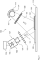
- Fig. 1 shows a schematic representation of a device 100 for testing a coating 101 of a document 103.
- the device 100 comprises an image sensor 105, an illumination device 107, a test structure 109, a holder 113 for the document 103, a processor 115, a reflective arrangement 117, a Display 119, an optical filter 123, a lens 121, an image camera 127 and a light source 125.
- the device 100 for testing the coating 101 of the document 103 includes the image sensor 105 and the lighting device 107 with the test structure 109, the lighting device 107 being designed to illuminate the test structure 109 in order to emit structured light in the direction of the document 103. Furthermore, the device 100 includes the holder 113 arranged in the beam path 111 of the structured light, into which the document 103 can be inserted in order to reflect the structured light through the document 103 in the direction of the image sensor 105, and the processor 115, which is designed, an image parameter to determine the image recording of the test structure, and to compare the image parameter with a reference parameter in order to test the coating 101 of the document 103.
- the document 103 can be one of the following documents 103: identity document, such as an ID card, passport, access control card, authorization card, company ID card, tax stamp or ticket, driver's license or vehicle ID card, means of payment, for example a bank card or credit card.
- identity document such as an ID card, passport, access control card, authorization card, company ID card, tax stamp or ticket, driver's license or vehicle ID card, means of payment, for example a bank card or credit card.
- the document 103 may include security features such as holograms, watermarks, microwriting, or optically variable ink.
- the document 103 can be single- or multi-layered or paper- and/or plastic-based.
- the document 103 can be constructed from plastic-based films, which are assembled into a card body by gluing and/or laminating, the films preferably having similar material properties.
- the document 103 can be made of polycarbonate.
- the coating 101 can be a layer of varnish or an application of varnish to protect the document 103 from wear and/or contamination and to increase its service life.
- the coating 101 can protect the document 103 from UV radiation.
- the coating 101 can be light-transparent or partially light-transparent.
- the lighting device 107 can include the light source 125, which is arranged in a housing.
- the housing can have a breakthrough on a side facing the test structure 109 for emitting a light beam directed onto the test structure 109.
- the test structure 109 can be arranged at this breakthrough.
- the holder 113 can include a storage area with a recess for the document 103. Furthermore, the holder can include a fastening device, for example a clip or an insert, for the document 103.
- the holder 113 can be arranged at such a distance from the lighting device 107 that the structured light illuminates the entire surface of the document 103 or only illuminates a specific area of the document 103, for example the area of a photograph.
- the processor 115 may be a microprocessor and may include memory. Furthermore, the processor 115 can be integrated into a data processing device connected to the device 100, for example a desktop computer or a laptop.
- the light source 125 may include an infrared light source, such as a thermal light source, an LED, or a laser.
- the thermal light source can be one Glow coil, a glow wire or a glow rod made of a heat-resistant material, for example tungsten or silicon carbide, which can emit infrared radiation particularly efficiently in the form of thermal radiation when heated above 1000 ° C.
- the lighting device 107 may include the reflective arrangement 117.
- the reflective arrangement 117 can be a parabolic mirror or a concave mirror, which partially encloses the lighting device 125.
- the reflective arrangement 117 may comprise a plurality of mirrors or reflectors which partially enclose the lighting device.
- the reflective arrangement 117 can align the light emitted by the light source 125 in the direction of the test structure 109 and the document 103, and thus increase the intensity of the light in the beam path 111.
- the test structure 109 can be a grid, in particular a line grid, which is designed as a transmission grid.
- the test structure in Fig. 1 is, for example, a transmission grating which is arranged in the beam path 111 between the light source 125 and the document.
- the structured light created when the radiation passes through the transmission grating can, after reflection on the document 103, be recorded in the image sensor 105 in order to obtain an image of the transmission grating.
- test structure 109 can be a reflection grating.
- This reflection grid can be arranged in the device 100 in such a way that at least part of the light generated by the light source 125 hits the reflection grid and is reflected as structured light in the direction of the document 103, the reflection of this light on the document 103 in the image sensor 105 can be recorded to obtain a recording of the reflection grating.
- the device 100 may include the optical filter 123 to filter or spectrally shape the structured light.
- the optical filter 123 can be arranged in the beam path 111 of the structured light, for example between the lighting device 107 and the document 103 or between the document 103 and the image sensor 105.
- the optical filter 123 may be a high-pass filter, a low-pass filter or a band-pass filter.
- the light source 125 is a thermal light source and the image sensor 105 is one infrared-sensitive image sensor 105, in particular a near-infrared-sensitive image sensor 105, the optical filter 123 can be a near-infrared-transmitting filter which, for example, filters out visible light, UV light, and/or middle and far infrared light from the beam path 111.
- the image sensor 105 can be a semiconductor sensor, in particular a CCD sensor.
- the semiconductor material of the sensor can be silicon or indium gallium arsenide.
- the device 100 may include the lens 121, wherein the lens 121 may be located in front of the image sensor 105.
- the objective 121 may include at least one lens and/or at least one mirror and/or at least one diffraction grating.
- the lens 121 can produce a focused image of the test structure 109 on the image sensor 105.
- the lens 121 can be arranged at a distance from the image sensor 105 that corresponds to the image width of the lens 121.
- the lens 121 can be designed and arranged in the device 100 in such a way that the size of the image of the test structure 109 corresponds to the size of the image sensor 105.
- an image parameter of the image can be determined particularly efficiently.
- the image sensor 105 and the lens 121 can be arranged in the image camera 127.
- the image camera 127 can be a digital camera, a digital SLR camera, or a smartphone with an integrated image sensor 105.
- the image camera 127 can be connected to a data processing device, for example a desktop computer or a laptop, to transmit the image recording.
- a data processing device for example a desktop computer or a laptop
- the device 100 may include a display 119 for indicating detection of the coating 101 or a coating defect.
- the display 119 can be a light display or a display, for example an LCD display, an OLED display or a film display.
- the display 119 can be integrated into the image camera 127 or a connected one Data processing device must be integrated.
- the display 119 can be connected to the processor 115.
- the image camera 127 may include the optical filter 123.
- the image camera 127 can include the processor 115 and the determination of the image parameter and the comparison with the reference parameter can take place in the image camera 127.
- Fig. 2a shows a schematic representation of a high-contrast image recording 201 of a test structure 109
- Fig. 2b shows a schematic representation of a low-contrast image recording 205 of a test structure 109.
- the high-contrast image recording 201 in Fig. 2a can be an image recording of a test structure 109, which was recorded with a document 103 without coating 101.
- the low-contrast image recording 205 in Fig. 2b can be a recording of the same test structure as in Fig. 2a be, which was recorded with a document 103 with coating 101.
- the contrast refers to differences in brightness in the image recordings, such as the difference between the dark grid lines 203 of the grid structure and the bright areas between these grid lines 203.
- the decrease in the contrast of the grid structure in Fig. 2b can also be perceived as a decrease in sharpness in the image capture.
- the loss of contrast in Fig. 2b lead to a widening of the grid lines 203 in the low-contrast image recording 205
- the test structures 109 in Fig. 2a and Fig. 2b are identical.
- the test structure 109 is a rectangular grid with horizontal and vertical grid lines 203.
- the round image of the rectangular grid corresponds to the part of the test structure 109 illuminated by the lighting device 107, which is imaged in focus on the image sensor 105.
- the round cross section can originate from a light beam with a round diameter generated by the lighting device 107.
- the loss of contrast in Fig. 2b can be caused by the coating 101 on the document 103.
- Reasons for the loss of contrast can be a surface roughness of the coating 101 and/or a shift in the focus of the image due to the beam path 111 shortened by the coating 101 and/or interference effects in the reflected structured light due to a superimposition of reflections on the top side of the coating and the bottom side of the coating
- the contrast loss can be used to test and/or detect the coating 101.
- the image recording can be evaluated with regard to an image parameter.
- the image parameter can be the image sharpness, the image contrast, or the image brightness, as well as a parameter calculated from at least one of these image parameters, for example a modulation transfer function or a Fourier transformation.
- a modulation of the brightness in the image recording can be analyzed.
- the image contrast is usually determined.
- the difference between the luminance of a dark structure in the image recording B D , for example the grid lines 203, and the luminance of a bright structure in the image recording B H , for example the bright area between the grid lines 203 can be determined.
- the image contrast can be a function of a spatial frequency.
- the image contrast can be a constant.
- the object contrast can correspond to the image contrast of the high-contrast image recording 201.
- the modulation transfer function is the ratio of the Image contrasts of the low-contrast image recording 205 and the high-contrast image recording 201.
- the coating 101 on the document 103 can be detected and/or checked by comparing the image parameters, for example the image contrasts and/or the modulation transfer functions, the low-contrast image recording 205 and the high-contrast image recording 201.
- image parameters for example the image contrasts and/or the modulation transfer functions, the low-contrast image recording 205 and the high-contrast image recording 201.
- an image parameter which was recorded with a coating-free reference surface can be used as a reference parameter.
- the processor 115 can store this reference parameter and compare a newly determined image parameter with the reference parameter for each new measurement.
- the processor 115 can be configured to detect a coating 101 if an image parameter of a document to be checked exceeds or falls below the reference parameter by a threshold value. Furthermore, the processor 115 can be configured to detect a coating error if the image parameter of the document 103 to be checked corresponds to the reference parameter or the deviation between the image parameter and the reference parameter falls below the threshold value.
- the processor 115 can be configured to detect a property of the coating 101, for example a minimum layer thickness of the coating 101, if the image parameter of a document 103 to be checked exceeds or falls below a further reference parameter. Furthermore, the processor 115 can be configured to determine a layer thickness of the coating 101 of the document 103 from the difference between the image parameter and the reference parameter.
- the image parameter can be assigned to an image section of the image recording and the processor 115 can be configured to determine a further image parameter of a further image section of the image recording of the test structure 109 and the image parameter and the further image parameter with the Compare reference parameters.
- the processor can check the distribution and/or the homogeneity of a layer thickness of the coating 101 of the document 103.
- Fig. 3 shows a schematic representation of the device 100 for testing the coating 101 of the document 103 according to an embodiment in which at least one uncoated reference surface 129 adjacent to the document 103 can or is inserted into the holder 113.
- a reference environment or a reference for determining the reference parameter can be created.
- the uncoated reference surface 129 can be in the form of an uncoated document.
- the uncoated reference surface 129 and the document 103 can be arranged in the beam path 111 of the structured light in such a way that a first image section of the image recording is assigned to the document 103 and a second image section of the image recording is assigned to the uncoated reference surface 129.
- the image parameter and the reference parameter are determined simultaneously or differentially from the image recording.
- the image parameter and the reference parameter are determined from an image recording, or the image parameter is determined from a first image recording and the reference parameter is determined from a second image recording.
- the spatial resolution of the image parameter can be influenced by a structure size of the test structure 109. Furthermore, by reducing the structure size of the test structure 109, for example by a Reducing the distances between the grid lines 203 of a grid, the spatial resolution of the image parameter can be increased.
Description
Die vorliegende Erfindung betrifft das Gebiet der Herstellung von Dokumenten.The present invention relates to the field of document production.
Dokumente, wie Personalausweise oder Führerscheine, weisen üblicherweise auf ihrer Oberfläche eine dünne Beschichtung, insbesondere eine Lackschicht, auf. Diese Beschichtung wird meist bei der Herstellung der Dokumente aufgebracht und dient der Versiegelung und dem Schutz der Dokumente. Aufgrund der geringen Schichtdicke der Beschichtung ist eine Prüfung oder Inspektion der Beschichtung schwierig.Documents such as identity cards or driving licenses usually have a thin coating, in particular a layer of varnish, on their surface. This coating is usually applied during the production of documents and serves to seal and protect the documents. Due to the thin layer thickness of the coating, testing or inspecting the coating is difficult.
Die Offenlegungsschrift
Die Patentschrift
Die Offenlegungsschrift
Die Offenlegungsschrift
Die Offenlegungsschrift
Es ist daher die Aufgabe der vorliegenden Erfindung, ein effizientes Konzept zum Prüfen einer Beschichtung eines Dokumentes zu schaffen.It is therefore the object of the present invention to create an efficient concept for checking a coating of a document.
Diese Aufgabe wird durch die Merkmale der unabhängigen Ansprüche gelöst. Vorteilhafte Weiterbildungsformen sind Gegenstand der abhängigen Patentansprüche, der Beschreibung sowie der Zeichnungen.This task is solved by the features of the independent claims. Advantageous forms of further training are the subject of the dependent patent claims, the description and the drawings.
Die vorliegende Erfindung basiert auf der Erkenntnis, dass die obige Aufgabe durch die Aufnahme einer an einem Dokument reflektierten Abbildung einer Teststruktur sowie durch die Ermittlung eines Bildparameters dieser Aufnahme gelöst werden kann.The present invention is based on the knowledge that the above task can be achieved by recording an image of a test structure reflected on a document and by determining an image parameter of this recording.
Gemäß einem ersten Aspekt betrifft die Erfindung eine Vorrichtung nach Anspruch 1. Dadurch wird der Vorteil erreicht, dass mit der Vorrichtung die Beschichtung des Dokumentes effektiv und berührungslos während des Herstellungsprozesses geprüft werden kann.According to a first aspect, the invention relates to a device according to claim 1. This achieves the advantage that the device can be used to check the coating of the document effectively and without contact during the manufacturing process.
Die Bildaufnahme der Teststruktur erfolgt mittels des Bildsensors.The image of the test structure is captured using the image sensor.
Das Dokument kann eines der folgenden Dokumente sein: Identitätsdokument, wie Personalausweis, Reisepass, Zugangskontrollausweis, Berechtigungsausweis, Unternehmensausweis, Steuerzeichen oder Ticket, Führerschein oder Kraftfahrzeugausweis, Wertdokument, Zahlungsmittel, beispielsweise eine Bankkarte oder Kreditkarte. Das Dokument kann Sicherheitsmerkmale, beispielsweise Hologramme, Wasserzeichen, Mikroschriften oder optisch veränderliche Tinte, umfassen. Das Dokument kann ein- oder mehrlagig bzw. papier- und/oder kunststoffbasiert sein. Das Dokument kann aus kunststoffbasierten Folien aufgebaut sein, welche zu einem Kartenkörper mittels Verkleben und/oder Laminieren zusammengefügt werden, wobei die Folien bevorzugt ähnliche stoffliche Eigenschaften aufweisen. Ferner kann das Dokument aus Polycarbonat gefertigt sein.The document can be one of the following documents: identity document, such as an identity card, passport, access control card, authorization card, company ID card, tax stamp or ticket, driver's license or vehicle ID, document of value, means of payment, for example a bank card or credit card. The document may include security features such as holograms, watermarks, microwriting, or optically variable ink. The document can be single or multi-layered or paper and/or plastic based. The document can be made up of plastic-based films, which are assembled into a card body by gluing and/or laminating, the films preferably having similar material properties. Furthermore, the document can be made of polycarbonate.
Bei der Beschichtung kann es sich um eine Lackschicht oder einen Lackauftrag zum Schutz vor Verschleiß und/oder Verschmutzung des Dokumentes sowie zur Erhöhung der Lebensdauer handeln. Die Beschichtung kann das Dokument vor UV-Strahlung schützen. Ferner kann die Beschichtung lichttransparent oder teilweise lichttransparent sein.The coating can be a layer of varnish or an application of varnish to protect the document from wear and/or contamination and to increase its service life. The coating can protect the document from UV radiation. Furthermore, the coating can be light-transparent or partially light-transparent.
Die Beleuchtungseinrichtung kann eine Lichtquelle umfassen, welche in einem Gehäuse angeordnet ist. Das Gehäuse kann an einer der Teststruktur zugewandten Seite einen Durchbruch zur Emission eines auf die Teststruktur gerichteten Lichtstrahles aufweisen. Die Teststruktur kann an diesem Durchbruch angeordnet sein.The lighting device can comprise a light source which is arranged in a housing. The housing can have a breakthrough on a side facing the test structure for emitting a light beam directed at the test structure. The test structure can be arranged at this breakthrough.
Die Halterung kann eine Ablagefläche mit einer Vertiefung für das Dokument umfassen. Ferner kann die Halterung eine Befestigungsvorrichtung, beispielsweise eine Klammer oder einen Einschub, für das Dokument umfassen. Die Halterung kann in einem solchen Abstand zu der Beleuchtungseinrichtung angeordnet sein, dass das strukturierte Licht das Dokumentes vollflächig beleuchtet oder nur einen bestimmten Bereich des Dokumentes, beispielsweise den Bereich eines Lichtbildes, beleuchtet.The holder can include a storage surface with a recess for the document. Furthermore, the holder can comprise a fastening device, for example a clip or an insert, for the document. The holder can be arranged at such a distance from the lighting device that the structured light illuminates the entire surface of the document or only illuminates a specific area of the document, for example the area of a photograph.
Der Prozessor kann ein Mikroprozessor sein und kann einen Speicher umfassen. Ferner kann der Prozessor in ein an die Vorrichtung angeschlossenes Datenverarbeitungsgerät, beispielsweise ein Desktop-Computer oder ein Laptop, integriert sein.The processor may be a microprocessor and may include memory. Furthermore, the processor can be integrated into a data processing device connected to the device, for example a desktop computer or a laptop.
Gemäß einer Ausführungsform ist die Beleuchtungseinrichtung ausgebildet, die Teststruktur zu durchleuchten, d.h. derart zu beleuchten, dass die Teststruktur durchleuchtet wird. Hierbei wird Licht durch die Teststruktur hindurch gesendet, wodurch das Licht strukturiert wird. Die Beleuchtungseinrichtung kann die Teststruktur jedoch derart beleuchten, dass das strukturierte Licht durch eine Reflexion des einfallenden Lichtes an der Teststruktur erhalten wird.According to one embodiment, the lighting device is designed to illuminate the test structure, i.e. to illuminate it in such a way that the test structure is illuminated. Here, light is sent through the test structure, which structures the light. However, the lighting device can illuminate the test structure in such a way that the structured light is obtained by reflecting the incident light on the test structure.
Gemäß einer Ausführungsform umfasst die Beleuchtungseinrichtung eine Infrarotlichtquelle, insbesondere eine thermische Infrarotlichtquelle, wobei der Bildsensor ein infrarotsensitiver Bildsensor ist. Dadurch wird der Vorteil erreicht, dass die Bildaufnahme nicht durch gestreutes Weißlich verfälscht wird.According to one embodiment, the lighting device comprises an infrared light source, in particular a thermal infrared light source, wherein the image sensor is an infrared-sensitive image sensor. This has the advantage that the image recording is not distorted by scattered whitish.
Die Infrarotlichtquelle kann eine thermische Lichtquelle, eine LED oder ein Laser sein. Die thermische Lichtquelle kann eine Glühwendel, ein Glühdraht oder ein Glühstab aus hitzebeständigen Materialien, beispielsweise Wolfram oder Siliziumcarbid, sein. Die Infrarotlichtquelle und der Bildsensoren können für die Abstrahlung beziehungsweise die Detektion von Licht im nahen Infrarot zwischen 700 nm und 3000 nm ausgelegt sein.The infrared light source can be a thermal light source, an LED or a laser. The thermal light source can be a filament, a filament or a glow rod made of heat-resistant materials, for example tungsten or silicon carbide. The infrared light source and the image sensors can be designed for the emission or detection of light in the near infrared between 700 nm and 3000 nm.
Gemäß einer Ausführungsform umfasst die Beleuchtungseinrichtung eine reflektierende Anordnung, insbesondere eine Parabolspiegelanordnung, um das strukturierte Licht auszurichten. Dadurch wird der Vorteil erreicht, dass die Intensität des auf dem Bildsensor auftreffenden reflektierten Lichtes verstärkt werden kann und somit die Bildqualität der Bildaufnahme verbessert werden kann.According to one embodiment, the lighting device comprises a reflective arrangement, in particular a parabolic mirror arrangement, to align the structured light. This achieves the advantage that the intensity of the reflected light striking the image sensor can be increased and thus the image quality of the image recording can be improved.
Die reflektierende Anordnung kann ein die Beleuchtungseinrichtung zumindest teilweise umgebender Parabolspiegel oder Hohlspiegel sein, welcher das von der Beleuchtungseinrichtung emittierte Licht auf die Teststruktur ausrichtet. Ferner kann die reflektierende Anordnung mehrere zusammengesetzte Spiegeln oder Reflektoren umfassen, welche die Beleuchtungseinrichtung teilweise umgeben. Bei der Beleuchtungseinrichtung kann es sich ferner um eine Lampe mit reflektierendem Schirm, beispielsweise eine Schreibtischlampe, handeln.The reflective arrangement can be a parabolic mirror or concave mirror that at least partially surrounds the lighting device and which aligns the light emitted by the lighting device onto the test structure. Furthermore, the reflective arrangement can comprise a plurality of assembled mirrors or reflectors which partially surround the lighting device. The lighting device can also be a lamp with a reflective shade, for example a desk lamp.
Gemäß der Erfindung ist die Teststruktur ein Gitter, insbesondere ein Transmissionsgitter oder ein Liniengitter mit einen konstanten oder einem variablen Linienabstand. Dadurch wird der Vorteil erreicht, dass das strukturierte Licht, welches durch die Beleuchtung der Teststruktur entsteht, ebenfalls eine regelmäßige Gitterstruktur aufweist. Durch die regelmäßige Struktur des strukturierten Lichtes kann eine effiziente und präzise Ermittlung des Bildparameters erfolgen.According to the invention, the test structure is a grid, in particular a transmission grid or a line grid with a constant or a variable line spacing. This has the advantage that the structured light created by illuminating the test structure also has a regular grid structure. The regular structure of the structured light allows the image parameter to be determined efficiently and precisely.
Gemäß einer Ausführungsform umfasst die Vorrichtung einen optischen Filter, insbesondere einen Hochpassfilter, einen Tiefpassfilter oder einen Bandpassfilter, um das strukturierte Licht zu filtern oder spektral zu formen. Dadurch wird der Vorteil erreicht, dass das Spektrum des strukturierten Lichtes auf einen Detektionsbereich des Bildsensors eingeschränkt werden kann und die ungewollte Detektion von Umgebungslicht, insbesondere gestreutem Weißlich, vermieden werden kann.According to one embodiment, the device comprises an optical filter, in particular a high-pass filter, a low-pass filter or a bandpass filter, in order to filter or spectrally shape the structured light. This achieves the advantage that the spectrum of the structured light can be limited to a detection area of the image sensor and the unwanted detection of ambient light, in particular scattered whitish, can be avoided.
Gemäß einer Ausführungsform umfasst die Vorrichtung ein Objektiv, welches dem Bildsensor vorgelagert ist, und mit welchem eine fokussierte Abbildung der Teststruktur auf dem Bildsensor erzeugt wird. Dadurch wird der Vorteil erreicht, dass eine optimal fokussierte Abbildung der Teststruktur in dem Bildsensor erfolgen kann und somit der Bildparameter besonders effizient ermittelt werden kann.According to one embodiment, the device comprises a lens which is located in front of the image sensor and with which a focused image of the test structure is generated on the image sensor. This achieves the advantage that an optimally focused imaging of the test structure can take place in the image sensor and thus the image parameter can be determined particularly efficiently.
Gemäß einer Ausführungsform ist das Objektiv ausgebildet die Oberfläche des Dokumentes und/oder die Oberfläche der Beschichtung des Dokumentes auf dem Bildsensor zu defokussieren. Dadurch wird der Vorteil erreicht, dass die Abbildung der Teststruktur nicht durch eine Abbildung der Oberfläche des Dokumentes verfälscht wird. Gemäß einer Ausführungsform sind der Bildsensor und das Objektiv in einer Bildkamera angeordnet. Dadurch wird der Vorteil erreicht, dass eine vereinfachte Herstellung der Vorrichtung erfolgen kann.According to one embodiment, the lens is designed to defocus the surface of the document and/or the surface of the coating of the document on the image sensor. This has the advantage that the image of the test structure is not distorted by an image of the surface of the document. According to one embodiment, the image sensor and the lens are arranged in an image camera. This achieves the advantage that the device can be manufactured in a simplified manner.
Bei der Bildkamera kann es sich um eine Digitalkamera, eine digitale Spiegelreflexkamera, oder ein Smartphone mit integriertem Bildsensor handeln. Die Bildkamera kann mit einem Datenverarbeitungsgerät, beispielsweise einem Desktop-Computer oder einen Laptop, zur Übermittlung der Bildaufnahme verbunden sein.The image camera can be a digital camera, a digital SLR camera, or a smartphone with an integrated image sensor. The image camera can be connected to a data processing device, for example a desktop computer or a laptop, to transmit the image recording.
Gemäß einer Ausführungsform ist der Bildsensor ein Halbleitersensor, insbesondere ein CCD-Sensor. Dadurch wird der Vorteil erreicht, dass eine besonders kostengünstige Herstellung der Vorrichtung ermöglicht wird.According to one embodiment, the image sensor is a semiconductor sensor, in particular a CCD sensor. This has the advantage that a particularly cost-effective production of the device is possible.
Gemäß der Erfindung ist der Prozessor ausgebildet, die Beschichtung zu detektieren, falls der Bildparameter und der Referenzparameter unterschiedlich sind, insbesondere falls der Bildparameter geringer als der Referenzparameter ist. Dadurch wird der Vorteil erreicht, dass eine effiziente Detektion der Beschichtung über den Vergleich des Bildparameters mit dem Referenzparameter erfolgen kann.According to the invention, the processor is designed to detect the coating if the image parameter and the reference parameter are different, in particular if the image parameter is lower than the reference parameter. This achieves the advantage that efficient detection of the coating can take place by comparing the image parameter with the reference parameter.
Gemäß der Erfindung ist der Prozessor ausgebildet, aus dem Unterschied zwischen dem Bildparameter und dem Referenzparameter eine Schichtdicke der Beschichtung des Dokumentes zu ermitteln. Dadurch wir der Vorteil erreicht, dass zusätzlich zur Detektion der Beschichtung die Schichtdicke der Beschichtung effizient ermittelt werden kann.According to the invention, the processor is designed to determine a layer thickness of the coating of the document from the difference between the image parameter and the reference parameter. This has the advantage that, in addition to detecting the coating, the layer thickness of the coating can be determined efficiently.
Gemäß der Erfindung ist der Bildparameter einem Bildabschnitt der Bildaufnahme zugeordnet, wobei der Prozessor ausgebildet ist, einen weiteren Bildparameter eines weiteren Bildabschnitts der Bildaufnahme der Teststruktur zu bestimmen, und wobei der Prozessor ausgebildet ist, den Bildparameter und den weiteren Bildparameter mit dem Referenzparameter zu vergleichen, um die Verteilung oder die Homogenität einer Schichtdicke der Beschichtung des Dokumentes zu prüfen. Dadurch wird der Vorteil erreicht, dass die Homogenität der Beschichtung des Dokumentes mit einer Bildaufnahme effizient ermittelt werden kann.According to the invention, the image parameter is assigned to an image section of the image recording, the processor being designed to determine a further image parameter of a further image section of the image recording of the test structure, and the processor being designed to compare the image parameter and the further image parameter with the reference parameter, to check the distribution or homogeneity of a layer thickness of the coating on the document. This has the advantage that the homogeneity of the coating on the document can be efficiently determined using an image.
Gemäß der Erfindung ist in die Halterung benachbart zum Dokument zumindest eine unbeschichtete Referenzfläche einsetzbar, wobei ein erster Bildabschnitt der Bildaufnahme dem Dokument zugeordnet ist, wobei ein zweiter Bildabschnitt der Bildaufnahme der unbeschichteten Referenzfläche zugeordnet ist, und wobei der Prozessor ausgebildet ist, den Referenzparameter als Bildparameter des zweiten Bildabschnitts zu bestimmen. Dadurch wird der Vorteil erreicht, dass die Bestimmung des Bildparameters und des Referenzparameters mit einer Bildaufnahme und/oder unter gleichen Bedingungen erfolgen kann. Die unbeschichtete Referenzfläche ist ein unbeschichtetes Dokument, d.h. ein Dokument ohne Beschichtung, sein.According to the invention, at least one uncoated reference surface can be inserted into the holder adjacent to the document, a first image section of the image recording being assigned to the document, a second image section of the image recording being assigned to the uncoated reference surface, and the processor being designed to use the reference parameter as an image parameter of the second image section. This achieves the advantage that the determination of the image parameter and the reference parameter can be carried out with an image recording and/or under the same conditions. The uncoated reference surface is an uncoated document, ie a document without a coating.
Gemäß einer Ausführungsform weist die Vorrichtung eine Anzeige zum Anzeigen einer Detektion der Beschichtung oder eines Beschichtungsfehlers auf. Dadurch wird der Vorteil erreicht, dass ein Benutzer effizient über die Detektion der Beschichtung informiert werden kann.According to one embodiment, the device has a display for indicating detection of the coating or a coating defect. This has the advantage that a user can be efficiently informed about the detection of the coating.
Bei der Anzeige kann es sich um eine Leuchtanzeige oder ein Display, beispielsweise ein LCD-Display, ein OLED-Display oder ein Foliendisplay, handeln.The display can be a light display or a display, for example an LCD display, an OLED display or a film display.
Gemäß einer Ausführungsform ist der jeweilige Bildparameter zumindest einer der folgenden Bildparamater: Bildschärfe, Bildkontrast, Bildhelligkeit, Fourier-Transformation. Dadurch wird der Vorteil erreicht, dass eine effiziente Auswertung der Bildaufnahme erfolgen kann. Gemäß der Erfindung ist der jeweilige Bildparameter eine ModulationsübertragungsfunktionAccording to one embodiment, the respective image parameter is at least one of the following image parameters: image sharpness, image contrast, image brightness, Fourier transformation. This has the advantage that the image recording can be evaluated efficiently. According to the invention, the respective image parameter is a modulation transfer function
Handelt es sich bei dem Bildparameter um eine Modulationsübertragungsfunktion, so wird ein Kontrastverlust in der Abbildung der Teststruktur aufgrund der Beschichtung ermittelt. Hierzu wird ein Kontrastverlauf in der Abbildung der Teststruktur analysiert. Diese Analyse wird mit einem Dokument mit Beschichtung und einem Dokument ohne Beschichtung vorgenommen. Der Bildparameter des Dokuments ohne Beschichtung wird bei dieser Analyse als Referenzparameter verwendet.If the image parameter is a modulation transfer function, a loss of contrast in the image of the test structure due to the coating is determined. For this purpose, a contrast curve in the image of the test structure is analyzed. This analysis is performed on a coated document and an uncoated document. The image parameter of the document without coating is used as the reference parameter in this analysis.
Gemäß einem zweiten Aspekt betrifft die Erfindung ein Verfahren nach Anspruch 10.According to a second aspect, the invention relates to a method according to claim 10.
Gemäß der Erfindung ist der Referenzparameter ein Bildparameter einer Bildaufnahme einer beschichtungsfreien Referenzfläche, und zwar eines oder des Dokumentes ohne Beschichtung. Dadurch wird der Vorteil erreicht, dass der Referenzparameter effizient bestimmt werden kann, und dass die Unterschiede zwischen dem Referenzparameter und dem Bildparameter des Dokumentes durch die Beschichtung des Dokumentes verursacht werden.According to the invention, the reference parameter is an image parameter Image capture of a coating-free reference surface, namely one or the document without coating. This achieves the advantage that the reference parameter can be determined efficiently and that the differences between the reference parameter and the image parameter of the document are caused by the coating of the document.
Gemäß der Erfindung wird aus dem Unterschied zwischen dem Bildparameter und dem Referenzparameter eine Schichtdicke der Beschichtung des Dokumentes ermittelt. Dadurch wir der Vorteil erreicht, dass zusätzlich zur Detektion der Beschichtung die Schichtdicke der Beschichtung effizient ermittelt werden kann.According to the invention, a layer thickness of the coating of the document is determined from the difference between the image parameter and the reference parameter. This has the advantage that, in addition to detecting the coating, the layer thickness of the coating can be determined efficiently.
Gemäß der Erfindung ist der Bildparameter einem Bildabschnitt der Bildaufnahme zugeordnet, wobei ein weiterer Bildparameter eines weiteren Bildabschnitts der Bildaufnahme der Teststruktur bestimmt wird, und wobei der Bildparameter und der weiteren Bildparameter mit dem Referenzparameter verglichen werden, um die Verteilung oder die Homogenität einer Schichtdicke der Beschichtung des Dokumentes zu prüfen. Dadurch wird der Vorteil erreicht, dass die Homogenität der Beschichtung des Dokumentes mit einer Bildaufnahme effizient ermittelt werden kann.According to the invention, the image parameter is assigned to an image section of the image recording, wherein a further image parameter of a further image section of the image recording of the test structure is determined, and wherein the image parameter and the further image parameter are compared with the reference parameter in order to determine the distribution or the homogeneity of a layer thickness of the coating of the document to check. This has the advantage that the homogeneity of the coating on the document can be efficiently determined using an image.
Gemäß der Erfindung wird benachbart zum Dokument zumindest eine unbeschichtete Referenzfläche angeordnet, wobei ein erster Bildabschnitt der Bildaufnahme dem Dokument zugeordnet ist, wobei ein zweiter Bildabschnitt der Bildaufnahme der unbeschichteten Referenzfläche zugeordnet ist, und wobei der Referenzparameter als Bildparameter des zweiten Bildabschnitts bestimmt wird. Dadurch wird der Vorteil erreicht, dass die Bestimmung des Bildparameters und des Referenzparameters mit einer Bildaufnahme und/oder unter gleichen Bedingungen erfolgen kann.According to the invention, at least one uncoated reference surface is arranged adjacent to the document, with a first image section of the image recording being assigned to the document, with a second image section of the image recording being assigned to the uncoated reference surface, and with the reference parameter being determined as the image parameter of the second image section. This achieves the advantage that the determination of the image parameter and the reference parameter can be carried out with an image recording and/or under the same conditions.
Gemäß einer Ausführungsform erfolgt die Beleuchtung der Teststruktur mit Infrarotlicht, um eine Infrarotbildaufnahme der Teststruktur in dem Bildsensor zu erhalten. Dadurch wird der Vorteil erreicht, dass eine Beeinflussung der Bildaufnahme aufgrund des sichtbaren Umgebungslichtes vermieden werden kann.According to one embodiment, the test structure is illuminated with infrared light in order to obtain an infrared image recording of the test structure in the image sensor. This has the advantage that influences on the image recording due to the visible ambient light can be avoided.
Gemäß der Erfindung ist die Teststruktur ein Gitter, insbesondere ein Transmissionsgitter oder ein Liniengitter mit einen konstanten oder einem variablen Linienabstand. Dadurch wird der Vorteil erreicht, dass das strukturierte Licht, welches durch die Beleuchtung der Teststruktur entsteht, ebenfalls eine regelmäßige Gitterstruktur aufweist. Durch die regelmäßige Struktur des strukturierten Lichtes kann eine effiziente und präzise Ermittlung des Bildparameters erfolgen.According to the invention, the test structure is a grid, in particular a transmission grid or a line grid with a constant or a variable line spacing. This has the advantage that the structured light created by illuminating the test structure also has a regular grid structure having. The regular structure of the structured light allows the image parameter to be determined efficiently and precisely.
Ist die Teststruktur ein Liniengitter und weist das strukturierte Licht eine entsprechende Linienstruktur auf, so kann ein Bildparameter, insbesondere eine Modulationsübertragungsfunktion, der Linienstruktur ermittelt werden. Ist die Teststruktur ferner ein Liniengitter mit variablem Linienabstand, so kann eine besonders effiziente Ermittlung des Bildparameters, insbesondere der Modulationsübertragungsfunktion, als Funktion der Ortsfrequenz des Liniengitters erfolgen. Das Liniengitter kann ein Rechteckgitter mit horizontalen und vertikalen Gitterlinien sein, die zueinander in einem 90° Winkel stehen können.If the test structure is a line grid and the structured light has a corresponding line structure, an image parameter, in particular a modulation transfer function, of the line structure can be determined. If the test structure is also a line grid with variable line spacing, a particularly efficient determination of the image parameter, in particular the modulation transfer function, can take place as a function of the spatial frequency of the line grid. The line grid can be a rectangular grid with horizontal and vertical grid lines that can be at a 90° angle to each other.
Gemäß einer Ausführungsform wird das strukturierte Licht mit einem optischen Filter, insbesondere einem Hochpassfilter, einem Tiefpassfilter oder einem Bandpassfilter, gefiltert oder spektral geformt. Dadurch wird der Vorteil erreicht, dass das Spektrum des strukturierten Lichtes auf einen Detektionsbereich des Bildsensors eingeschränkt werden kann und die ungewollte Detektion von Umgebungslicht, insbesondere gestreutem Weißlicht, vermieden werden kann.According to one embodiment, the structured light is filtered or spectrally shaped using an optical filter, in particular a high-pass filter, a low-pass filter or a bandpass filter. This achieves the advantage that the spectrum of the structured light can be limited to a detection area of the image sensor and the unwanted detection of ambient light, in particular scattered white light, can be avoided.
Gemäß einer Ausführungsform ist dem Bildsensor ein Objektiv vorgelagert, mit welchem eine fokussierte Abbildung der Teststruktur auf dem Bildsensors erzeugt wird. Dadurch wird der Vorteil erreicht, dass eine optimal fokussierte Abbildung der Teststruktur in dem Bildsensor erfolgen kann und somit der Bildparameter besonders effizient ermittelt werden kann.According to one embodiment, the image sensor is preceded by a lens with which a focused image of the test structure is generated on the image sensor. This achieves the advantage that an optimally focused imaging of the test structure can take place in the image sensor and thus the image parameter can be determined particularly efficiently.
Gemäß der Erfindung wird die Beschichtung detektiert, falls der Bildparameter und der Referenzparameter unterschiedlich sind, insbesondere falls der Bildparameter geringer als der Referenzparameter ist. Dadurch wird der Vorteil erreicht, dass eine effiziente Detektion der Beschichtung über den Vergleich des Bildparameters mit dem Referenzparameter erfolgen kann.According to the invention, the coating is detected if the image parameter and the reference parameter are different, in particular if the image parameter is lower than the reference parameter. This achieves the advantage that efficient detection of the coating can take place by comparing the image parameter with the reference parameter.
Weitere Ausführungsbeispiele werden Bezug nehmend auf die beiliegenden Zeichnungen näher erläutert. Es zeigen:
- Fig. 1
- eine schematische Darstellung einer Vorrichtung zum Prüfen einer Beschichtung eines Dokumentes;
- Fig. 2a
- eine schematische Darstellung einer kontrastreichen Bildaufnahme einer Teststruktur;
- Fig. 2b
- eine schematische Darstellung einer kontrastarmen Bildaufnahme einer Teststruktur; und
- Fig. 3
- eine schematische Darstellung einer Vorrichtung zum Prüfen einer Beschichtung eines Dokumentes.
- Fig. 1
- a schematic representation of a device for checking a coating of a document;
- Fig. 2a
- a schematic representation of a high-contrast image recording of a test structure;
- Fig. 2b
- a schematic representation of a low-contrast image recording of a test structure; and
- Fig. 3
- a schematic representation of a device for checking a coating of a document.
Die Vorrichtung 100 zum Prüfen der Beschichtung 101 des Dokumentes 103 umfasst den Bildsensor 105 und die Beleuchtungseinrichtung 107 mit der Teststruktur 109, wobei die Beleuchtungseinrichtung 107 ausgebildet ist, die Teststruktur 109 zu beleuchten, um strukturiertes Licht in Richtung des Dokumentes 103 auszusenden. Ferner umfasst die Vorrichtung 100 die im Strahlengang 111 des strukturierten Lichts angeordnete Halterung 113, in welche das Dokument 103 einsetzbar ist, um das strukturierte Licht durch das Dokument 103 in Richtung des Bildsensors 105 zu reflektieren und den Prozessor 115, welcher ausgebildet ist, einen Bildparameter der Bildaufnahme der Teststruktur zu bestimmen, und den Bildparameter mit einem Referenzparameter zu vergleichen, um die Beschichtung 101 des Dokumentes 103 zu prüfen.The
Das Dokument 103 kann eines der folgenden Dokumente 103 sein: Identitätsdokument, wie Personalausweis, Reisepass, Zugangskontrollausweis, Berechtigungsausweis, Unternehmensausweis, Steuerzeichen oder Ticket, Führerschein oder Kraftfahrzeugausweis, Zahlungsmittel, beispielsweise eine Bankkarte oder Kreditkarte.The
Das Dokument 103 kann Sicherheitsmerkmale, beispielsweise Hologramme, Wasserzeichen, Mikroschriften oder optisch veränderliche Tinte, umfassen. Das Dokument 103 kann ein- oder mehrlagig bzw. papier- und/oder kunststoffbasiert sein. Das Dokument 103 kann aus kunststoffbasierten Folien aufgebaut sein, welche zu einem Kartenkörper mittels Verkleben und/oder Laminieren zusammengefügt werden, wobei die Folien bevorzugt ähnliche stoffliche Eigenschaften aufweisen. Ferner kann das Dokument 103 aus Polycarbonat gefertigt sein.The
Bei der Beschichtung 101 kann es sich um eine Lackschicht oder einen Lackauftrag zum Schutz vor Verschleiß und/oder Verschmutzung des Dokumentes 103 sowie zur Erhöhung der Lebensdauer handeln. Die Beschichtung 101 kann das Dokument 103 vor UV-Strahlung schützen. Ferner kann die Beschichtung 101 lichttransparent oder teilweise lichttransparent sein.The
Die Beleuchtungseinrichtung 107 kann die Lichtquelle 125 umfassen, welche in einem Gehäuse angeordnet ist. Das Gehäuse kann an einer der Teststruktur 109 zugewandten Seite einen Durchbruch zur Emission eines auf die Teststruktur 109 gerichteten Lichtstrahles aufweisen. Die Teststruktur 109 kann an diesem Durchbruch angeordnet sein.The
Die Halterung 113 kann eine Ablagefläche mit einer Vertiefung für das Dokument 103 umfassen. Ferner kann die Halterung eine Befestigungsvorrichtung, beispielsweise eine Klammer oder einen Einschub, für das Dokument 103 umfassen. Die Halterung 113 kann in einem solchen Abstand zu der Beleuchtungseinrichtung 107 angeordnet sein, dass das strukturierte Licht das Dokument 103 vollflächig beleuchtet oder nur einen bestimmten Bereich des Dokumentes 103, beispielsweise den Bereich eines Lichtbildes, beleuchtet.The
Der Prozessor 115 kann ein Mikroprozessor sein und kann einen Speicher umfassen. Ferner kann der Prozessor 115 in ein an die Vorrichtung 100 angeschlossenes Datenverarbeitungsgerät, beispielsweise ein Desktop-Computer oder ein Laptop, integriert sein.The
Die Lichtquelle 125 kann eine Infrarotlichtquelle, beispielsweise eine thermische Lichtquelle, eine LED oder ein Laser, umfassen. Die thermische Lichtquelle kann eine Glühwendel, ein Glühdraht oder ein Glühstab aus einem hitzebeständiges Material, beispielsweise Wolfram oder Siliziumcarbid, umfassen, welche bei Erhitzung über 1000°C Infrarotstrahlung besonders effizient in Form von Wärmestrahlung emittieren können.The light source 125 may include an infrared light source, such as a thermal light source, an LED, or a laser. The thermal light source can be one Glow coil, a glow wire or a glow rod made of a heat-resistant material, for example tungsten or silicon carbide, which can emit infrared radiation particularly efficiently in the form of thermal radiation when heated above 1000 ° C.
Gemäß einer Ausführungsform kann die Beleuchtungseinrichtung 107 die reflektierende Anordnung 117 umfassen. Die reflektierende Anordnung 117 kann ein Parabolspiegel oder ein Hohlspiegel sein, welche die Beleuchtungseinrichtung 125 teilweise umschließen. Ferner kann die reflektierende Anordnung 117 eine Mehrzahl von Spiegeln oder Reflektoren umfassen, welche die Beleuchtungseinrichtung teilweise umschließen. Die reflektierende Anordnung 117 kann das von der Lichtquelle 125 emittierte Licht in Richtung der Teststruktur 109 und des Dokumentes 103 ausrichten, und somit die Intensität des Lichtes im Strahlengang 111 erhöhen.According to one embodiment, the
Die Teststruktur 109 kann ein Gitter, insbesondere ein Liniengitter, sein, welches als Transmissionsgitter ausgebildet ist. Die Teststruktur in
Ferner kann die Teststruktur 109 ein Reflexionsgitter sein. Dieses Reflexionsgitter kann derart in der Vorrichtung 100 angeordnet sein, dass zumindest ein Teil des von der Lichtquelle 125 erzeugten Lichtes auf das Reflexionsgitter trifft und als strukturiertes Licht in Richtung des Dokumentes 103 reflektiert wird, wobei die Reflektion dieses Lichtes an dem Dokument 103 in dem Bildsensor 105 aufgenommen werden kann, um eine Aufnahme des Reflexionsgitters zu erhalten.Furthermore, the
Gemäß einer Ausführungsform kann die Vorrichtung 100 den optischen Filter 123 umfassen, um das strukturierte Licht zu filtern oder spektral zu formen. Der optische Filter 123 kann im Strahlengang 111 des strukturierten Lichtes, beispielsweise zwischen der Beleuchtungseinrichtung 107 und dem Dokument 103 oder zwischen dem Dokument 103 und dem Bildsensor 105, angeordnet sein. Ferner kann der optische Filter 123 ein Hochpassfilter, ein Tiefpassfilter oder ein Bandpassfilter sein. Handelt es sich bei der Lichtquelle 125 um eine thermische Lichtquelle und bei dem Bildsensor 105 um einen infrarotsensitiven Bildsensor 105, insbesondere einen nahinfrarotsensitiven Bildsensor 105, so kann der optische Filter 123 ein nahinfrarotdurchlässiger Filter sein, welcher beispielsweise sichtbares Licht, UV-Licht, und/oder Mittel- und Ferninfrarotlicht aus dem Strahlengang 111 herausfiltert.According to one embodiment, the
Gemäß einer Ausführungsform kann der Bildsensor 105 ein Halbleitersensor, insbesondere ein CCD-Sensor, sein. Das Halbleitermaterial des Sensors kann Silizium oder Indium-Gallium-Arsenid sein.According to one embodiment, the
Gemäß einer Ausführungsform kann die Vorrichtung 100 das Objektiv 121 umfassen, wobei das Objektiv 121 dem Bildsensor 105 vorgelagert sein kann. Das Objektiv 121 kann mindestens eine Linse und/oder mindestens einen Spiegel und/oder mindestens ein Beugungsgitter umfassen. Das Objektiv 121 kann eine fokussierte Abbildung der Teststruktur 109 auf dem Bildsensor 105 erzeugen. Hierzu kann das Objektiv 121 in einem Abstand zu dem Bildsensor 105 angeordnet sein, der der Bildweite des Objektivs 121 entspricht. Ferner kann das Objektiv 121 auf eine solche Art und Weise ausgebildet und in der Vorrichtung 100 angeordnet sein, dass die Größe der Abbildung der Teststruktur 109 der Größe des Bildsensors 105 entspricht. Bei optimaler Fokussierung der Abbildung der Teststruktur auf dem Bildsensor 105 kann ein Bildparameter der Abbildung besonders effizient ermittelt werden.According to one embodiment, the
Gemäß einer Ausführungsform können der Bildsensor 105 und das Objektiv 121 in der Bildkamera 127 angeordnet sein. Die Bildkamera 127 kann eine Digitalkamera, eine digitale Spiegelreflexkamera, oder ein Smartphone mit integriertem Bildsensor 105 sein.According to one embodiment, the
Gemäß einer Ausführungsform kann die Bildkamera 127 mit einem Datenverarbeitungsgerät, beispielsweise einem Desktop-Computer oder einen Laptop, zur Übermittlung der Bildaufnahme verbunden sein.According to one embodiment, the
Gemäß einer Ausführungsform kann die Vorrichtung 100 eine Anzeige 119 zum Anzeigen der Detektion der Beschichtung 101 oder eines Beschichtungsfehlers umfassen. Die Anzeige 119 kann eine Leuchtanzeige oder ein Display, beispielsweise ein LCD-Display, ein OLED-Display oder ein Foliendisplay, sein. Gemäß einer weiteren Ausführungsform kann die Anzeige 119 in die Bildkamera 127 oder ein angeschlossenes Datenverarbeitungsgerät integriert sein. Ferner kann die Anzeige 119 mit dem Prozessor 115 verbunden sein.According to one embodiment, the
Gemäß einer Ausführungsform kann die Bildkamera 127 den optischen Filter 123 umfassen.According to one embodiment, the
Gemäß einer weiteren Ausführungsform kann die Bildkamera 127 den Prozessor 115 umfassen und kann die Ermittlung des Bildparameters und der Vergleich mit dem Referenzparameter in der Bildkamera 127 erfolgen.According to a further embodiment, the
Die kontrastreiche Bildaufnahme 201 in
Der Kontrast bezieht sich auf Helligkeitsunterschiede in den Bildaufnahmen, etwa den Unterschied zwischen dem dunklen Gitterlinien 203 der Gitterstruktur und den hellen Bereichen zwischen diesen Gitterlinien 203. Die Abnahme des Kontrastes der Gitterstruktur in
Die Teststrukturen 109 in
Der Kontrastverlust in
Gemäß einer Ausführungsform kann der Kontrastverlust zur Prüfung und/oder Detektion der Beschichtung 101 genutzt werden. Zu diesem Zweck kann eine Auswertung der Bildaufnahme hinsichtlich eines Bildparameters erfolgen. Bei dem Bildparameter kann es sich um die Bildschärfe, den Bildkontrast, oder die Bildhelligkeit, sowie einen aus mindestens einen dieser Bildparameter berechneten Parameter, beispielsweise eine Modulationsübertragungsfunktion oder eine Fourier-Transformation, handeln.According to one embodiment, the contrast loss can be used to test and/or detect the
Bei einer Prüfung der Beschichtung 101 mittels Modulationsübertragungsfunktion, kann eine Modulation der Helligkeit in der Bildaufnahme analysiert werden. Zu diesem Zweck wird meist der Bildkontrast ermittelt. Hierzu kann zunächst die Differenz der Leuchtdichte einer dunklen Struktur in der Bildaufnahme BD, beispielsweise den Gitterlinien 203, und der Leuchtdichte einer hellen Struktur in der Bildaufnahme BH, beispielsweise den hellen Bereich zischen den Gitterlinien 203, ermittelt werden. Der Bildkontrast K kann als das Verhältnis der Differenz und der Summe dieser Leuchtdichten definiert werden, gemäß: K = (BH - BD) / (BH + BD), mit 0 ≤ K ≤ 1.When testing the
Bei einem Gitter mit variabler Gitterkonstante, kann der Bildkontrast eine Funktion einer Ortsfrequenz sein. Bei einem Gitter mit konstanter Gitterkonstante, wie in
Die Modulationsübertragungsfunktion M entspricht dem Verhältnis des Bildkontrastes K und eines Objektkontrastes O, gemäß: M = K / O. Der Objektkontrast kann auf die gleiche Art und Weise wie der Bildkontrast ermittelt werden, wobei Idealwerte für die Leuchtdichten angenommen werden können, beispielsweise BH = 1 und BD = 0. Ferner kann der Objektkontrast dem Bildkontrast der kontrastreichen Bildaufnahme 201 entsprechen. In diesem Fall ist die Modulationsübertragungsfunktion das Verhältnis der Bildkontraste der kontrastarmen Bildaufnahme 205 und der kontrastreichen Bildaufnahme 201.The modulation transfer function M corresponds to the ratio of the image contrast K and an object contrast O, according to: M = K / O. The object contrast can be determined in the same way as the image contrast, whereby ideal values for the luminances can be assumed, for example B H = 1 and B D = 0. Furthermore, the object contrast can correspond to the image contrast of the high-
Die Beschichtung 101 auf dem Dokument 103 kann über einen Vergleich der Bildparameter, beispielsweise der Bildkontraste und/oder der Modulationsübertragungsfunktionen, der kontrastarmen Bildaufnahme 205 und der kontrastreichen Bildaufnahme 201 detektiert und/oder geprüft werden.The
Gemäß einer Ausführungsform kann ein Bildparameter welcher mit einer beschichtungsfreien Referenzfläche aufgenommen wurde, als Referenzparameter verwendet werden. Der Prozessor 115 kann diesen Referenzparameter speichern und für bei jeder neue Messung einen neu ermittelten Bildparameter mit dem Referenzparameter vergleichen.According to one embodiment, an image parameter which was recorded with a coating-free reference surface can be used as a reference parameter. The
Gemäß einer Ausführungsform kann der Prozessor 115 konfiguriert sein, eine Beschichtung 101 zu detektieren, falls ein Bildparameter eines zu prüfenden Dokumentes den Referenzparameter um einen Schwellwert überschreitet oder unterschreitet. Ferner kann der Prozessor 115 konfiguriert sein, einen Beschichtungsfehler zu detektieren, falls der Bildparameter des zu prüfenden Dokumentes 103 dem Referenzparameter entspricht, bzw. die Abweichung zwischen Bildparameter und Referenzparameter den Schwellwert unterschreitet.According to one embodiment, the
Gemäß einer weiteren Ausführungsform kann der Prozessor 115 konfiguriert sein eine Eigenschaft der Beschichtung 101, beispielsweise eine Mindestschichtdicke der Beschichtung 101, zu detektieren, falls der Bildparameter eines zu prüfenden Dokumentes 103 einen weiteren Referenzparameter überschreitet oder unterschreitet. Ferner kann der Prozessor 115 konfiguriert sein, aus dem Unterschied zwischen Bildparameter und Referenzparameter eine Schichtdicke der Beschichtung 101 des Dokumentes 103 zu ermitteln.According to a further embodiment, the
Gemäß einer weiteren Ausführungsform kann der Bildparameter einem Bildabschnitt der Bildaufnahme zugeordnet sein und kann der Prozessor 115 konfiguriert sein, einen weiteren Bildparameter eines weiteren Bildabschnitts der Bildaufnahme der Teststruktur 109 zu bestimmen und den Bildparameter und den weiteren Bildparameter mit dem Referenzparameter zu vergleichen. Auf diese Art und Weise kann der Prozessor die Verteilung und/oder die Homogenität einer Schichtdicke der Beschichtung 101 des Dokumentes 103 prüfen.According to a further embodiment, the image parameter can be assigned to an image section of the image recording and the
Durch die Anordnung der unbeschichtete Referenzfläche 129 in der Halterung 113 kann eine Referenzumgebung bzw. eine Referenz für die Bestimmung des Referenzparameters geschaffen werden.By arranging the
Gemäß einer weiteren Ausbildungsform kann die unbeschichtete Referenzfläche 129 in der Gestalt eines unbeschichteten Dokumentes vorliegen.According to a further form of training, the
Gemäß einer weiteren Ausbildungsform können die unbeschichtete Referenzfläche 129 und das Dokumentes 103 im Strahlengang 111 des strukturierten Lichtes derart angeordnet sein, dass ein erster Bildabschnitt der Bildaufnahme dem Dokument 103 zugeordnet ist und ein zweiter Bildabschnitt der Bildaufnahme der unbeschichteten Referenzfläche 129 zugeordnet ist.According to a further embodiment, the
Gemäß einer weiteren Ausführungsform erfolgt die Bestimmung des Bildparameters und des Referenzparameters gleichzeitig oder differentiell aus der Bildaufnahme.According to a further embodiment, the image parameter and the reference parameter are determined simultaneously or differentially from the image recording.
Gemäß einer weiteren Ausführungsform erfolgt die Bestimmung des Bildparameters und des Referenzparameters aus einer Bildaufnahme, oder erfolgt die Bestimmung des Bildparameters aus einer ersten Bildaufnahme und die Bestimmung des Referenzparameters aus einer zweiten Bildaufnahme.According to a further embodiment, the image parameter and the reference parameter are determined from an image recording, or the image parameter is determined from a first image recording and the reference parameter is determined from a second image recording.
Gemäß einer weiteren Ausführungsform kann die Ortsauflösung des Bildparameters durch eine Strukturgröße der Teststruktur 109 beeinflusst werden. Ferner kann durch eine Verkleinerung der Strukturgröße der Teststruktur 109, beispielsweise durch eine Verkleinerung der Abstände der Gitterlinien 203 eines Gitters, die Ortsauflösung des Bildparameters erhöht werden.According to a further embodiment, the spatial resolution of the image parameter can be influenced by a structure size of the
- 100100
- Vorrichtungcontraption
- 101101
- BeschichtungCoating
- 103103
- Dokumentdocument
- 105105
- BildsensorImage sensor
- 107107
- BeleuchtungseinrichtungLighting device
- 109109
- TeststrukturTest structure
- 111111
- Strahlengangbeam path
- 113113
- Halterungbracket
- 115115
- Prozessorprocessor
- 117117
- reflektierende Anordnungreflective arrangement
- 119119
- AnzeigeAdvertisement
- 121121
- Objektivlens
- 123123
- optischer Filteroptical filter
- 125125
- Lichtquellelight source
- 127127
- BildkameraImage camera
- 129129
- unbeschichtete Referenzflächeuncoated reference surface
- 201201
- kontrastreiche Bildaufnahmehigh-contrast image capture
- 203203
- Gitterliniegrid line
- 205205
- kontrastarme Bildaufnahmelow-contrast image capture
Claims (15)
- A device (100) for testing a coating (101) of a document (103), comprising:an image sensor (105);an illumination device (107) comprising a test structure (109), wherein the illumination device (107) is configured to illuminate the test structure (109) in order to emit structured light towards the document (103);a holder (113) arranged in the beam path (111) of the structured light, wherein the document (103) is insertable into the holder in order to reflect the structured light through the document (103) towards the image sensor (105);a processor (115), which is configured to determine an image parameter of the image recording of the test structure (109) and to compare the image parameter with a reference parameter in order to test the coating (101) of the document (103),wherein the test structure (109) is a grating,wherein the processor (115) is configured to detect the coating (101) if the image parameter and the reference parameter are different,wherein the processor (115) is configured to determine a layer thickness of the coating (101) of the document (103) based on the difference between the image parameter and the reference parameter,wherein the image parameter is associated with an image section of the image recording, wherein the processor (115) is configured to determine a further image parameter of a further image section of the image recording of the test structure (109), and wherein the processor (115) is configured to compare the image parameter and the further image parameter with the reference parameter in order to test the distribution or the homogeneity of a layer thickness of the coating (101) of the document (103),wherein at least one uncoated reference surface (129) is insertable into the holder (113) adjacent to the document, wherein a first image section of the image recording is associated with the document (103), wherein a second image section of the image recording is associated with the uncoated reference surface (129), and wherein the processor (115) is configured to determine the reference parameter as image parameter of the second image section, wherein the uncoated reference surface (129) is a document without a coating,where the respective image parameter is the following image parameter: modulation transfer function,wherein the processor (115) is configured to determine a loss of contrast in the image of the test structure (109), wherein the processor (115) is configured to analyze a contrast curve in the image of the test structure (115) for this purpose, wherein this analysis is performed with the document with the coating (101) and with the document without coating, wherein the image parameter of the at least one uncoated reference surface (129) is used as a reference parameter in this analysis.
- The device (100) according to claim 1, wherein the illumination device (107) comprises an infrared light source, in particular a thermal infrared light source, and wherein the image sensor (105) is an infrared-sensitive image sensor (105).
- The device (100) according to claim 1 or 2, wherein the illumination device (107) comprises a reflecting arrangement (117), in particular a parabolic mirror arrangement, in order to align the structured light.
- The device (100) according to any one of the preceding claims, wherein the grating is a transmission grating or a line grating with a constant or a variable line spacing.
- The device (100) according to any one of the preceding claims, wherein the device (100) comprises an optical filter (123), in particular a high-pass filter, a low-pass filter or a band-pass filter, in order to filter or spectrally shape the structured light.
- The device (100) according to any one of the preceding claims, wherein the device comprises a lens (121) which is in front of the image sensor (105) and with which lens a focused image of the test structure can be generated on the image sensor.
- The device (100) according to any one of the preceding claims, wherein the processor (115) is configured to detect the coating (101) if the image parameter is less than the reference parameter.
- The device (100) according to any one of the preceding claims, wherein the device comprises a display (119) for displaying a detection of the coating (101) or a coating defect.
- The device (100) according to any one of the preceding claims, wherein the respective image parameter is at least one of the following image parameters: image sharpness, image contrast, image brightness, Fourier transformation.
- A method for testing a coating (101) of a document (103), comprising:illuminating a test structure (109) to emit structured light towards the document (103);reflecting the structured light through the document (103) towards an image sensor (105);recording the reflected structured light with an image sensor (105) in order to obtain an image recording of the test structure (109);determining an image parameter of the image recording; andcomparing the image parameter with a reference parameter in order to test the coating (101) of the document (103),wherein the test structure (109) is a grating,wherein the coating (101) is detected if the image parameter and the reference parameter are different,wherein a layer thickness of the coating of the document is determined based on the difference between the image parameter and the reference parameter,wherein the image parameter is associated with an image section of the image recording, wherein a further image parameter of a second image section of the image recording of the test structure (109) is determined, and wherein the image parameter and the further image parameter are compared with the reference parameter in order to test the distribution or the homogeneity of a layer thickness of the coating (101) of the document (103),wherein the reference parameter is an image parameter of an image recording of a uncoated reference surface (129), wherein the uncoated reference surface (129) is a document without a coating,wherein at least one uncoated reference surface (129) is arranged adjacent to the document, wherein a first image section of the image recording is associated with the document, wherein a second image section of the image recording is associated with the uncoated reference area (129), and wherein the reference parameter is determined as the image parameter of the second image section,where the respective image parameter is at least one of the following image parameters: modulation transfer function,
wherein a loss of contrast in the image of the test structure (109) is determined, wherein a contrast curve is determined in the image of the test structure (115) for this purpose, wherein this analysis is performed with the document with the coating (101) and with the document without coating, wherein the image parameter of the at least one uncoated reference surface (129) is used as a reference parameter in this analysis. - The method according to claim 10, wherein the reference parameter is an image parameter of an image recording of the identification document without a coating.
- The method according to claim 10 or 11, wherein the grating is a transmission grating or a line grating with a constant or a variable line spacing.
- The method according to any one of claims 10 to 12, wherein the structured light is filtered or spectrally shaped with an optical filter (123), in particular a high-pass filter, a low-pass filter or a band-pass filter.
- The method according to any one of claims 10 to 13, wherein a lens (121) is in front of the image sensor (105) with which lens a focused image of the test structure (109) is generated on the image sensor (105).
- The method according to any one of claims 10 to 14, wherein the coating (101) is detected if the image parameter is less than the reference parameter.
Applications Claiming Priority (1)
| Application Number | Priority Date | Filing Date | Title |
|---|---|---|---|
| DE102015113469.1A DE102015113469A1 (en) | 2015-08-14 | 2015-08-14 | Apparatus for testing a coating of a document |
Publications (2)
| Publication Number | Publication Date |
|---|---|
| EP3131070A1 EP3131070A1 (en) | 2017-02-15 |
| EP3131070B1 true EP3131070B1 (en) | 2023-10-11 |
Family
ID=56888909
Family Applications (1)
| Application Number | Title | Priority Date | Filing Date |
|---|---|---|---|
| EP16184003.8A Active EP3131070B1 (en) | 2015-08-14 | 2016-08-12 | Device for testing a coating of a document |
Country Status (2)
| Country | Link |
|---|---|
| EP (1) | EP3131070B1 (en) |
| DE (1) | DE102015113469A1 (en) |
Families Citing this family (4)
| Publication number | Priority date | Publication date | Assignee | Title |
|---|---|---|---|---|
| DE102017120035A1 (en) * | 2017-08-07 | 2019-02-07 | Bw Papersystems Hamburg Gmbh | Method and test device for checking the quality of results of mechanical processing of a sheet |
| CN110823515B (en) * | 2018-08-14 | 2022-02-01 | 宁波舜宇光电信息有限公司 | Structured light projection module multi-station detection device and detection method thereof |
| CN109738157A (en) * | 2018-12-11 | 2019-05-10 | 信利光电股份有限公司 | Field angle detection method, device and the readable storage medium storing program for executing of structured light projection device |
| CN111750785B (en) * | 2020-07-03 | 2021-08-24 | 重庆科技学院 | On-line measuring method and measuring device for coating thickness and coating quality |
Family Cites Families (6)
| Publication number | Priority date | Publication date | Assignee | Title |
|---|---|---|---|---|
| DE2055594A1 (en) * | 1969-11-13 | 1971-07-08 | Sira Instiute | Method and device for viewing objects |
| US4183665A (en) * | 1977-12-07 | 1980-01-15 | Ardac, Inc. | Apparatus for testing the presence of color in a paper security |
| US6639201B2 (en) * | 2001-11-07 | 2003-10-28 | Applied Materials, Inc. | Spot grid array imaging system |
| EP1496479A1 (en) * | 2003-07-08 | 2005-01-12 | Identification Systems DERMALOG GmbH | Reading Device for the automatic verification of documents |
| DE102009037553A1 (en) * | 2009-08-17 | 2011-02-24 | Baumer Innotec Ag | Sensor for contact-free detection of local and global presence or absence of transparent protective layer on substrate, has light pattern projector consisting of element for generating light pattern and projection lens |
| DE102011051781A1 (en) * | 2011-07-12 | 2013-01-17 | Göpel electronic GmbH | Deflectometric arrangement for surface inspection |
-
2015
- 2015-08-14 DE DE102015113469.1A patent/DE102015113469A1/en active Pending
-
2016
- 2016-08-12 EP EP16184003.8A patent/EP3131070B1/en active Active
Also Published As
| Publication number | Publication date |
|---|---|
| EP3131070A1 (en) | 2017-02-15 |
| DE102015113469A1 (en) | 2017-02-16 |
Similar Documents
| Publication | Publication Date | Title |
|---|---|---|
| EP3131070B1 (en) | Device for testing a coating of a document | |
| EP3555811A2 (en) | Verification of a security document | |
| DE19924750C2 (en) | Reading arrangement for information strips with optically coded information | |
| EP2577620B1 (en) | Device for testing the authenticity of valuable documents | |
| DE102006053788A1 (en) | Method for detecting contamination in the area of color transitions on value documents and means for carrying out the method | |
| DE10234431A1 (en) | Device and method for processing documents of value | |
| EP2380146B1 (en) | Method and device for examining value documents | |
| EP3047461B1 (en) | Device for verifying documents | |
| EP3782136B1 (en) | Method for the verification of a luminescent-material-based security feature | |
| DE102017102556A1 (en) | A method for verifying a security document and a security document, a device and a security element | |
| EP2686173B1 (en) | Security element having a 3d color effect and verification method and verification device for such a security element | |
| DE102013103527A1 (en) | Image recording system for image acquisition of features of an identification document | |
| DE102013103522A1 (en) | Image recording system for image acquisition of a feature of an identification document | |
| US10839634B2 (en) | Taggant system | |
| EP1197926B1 (en) | Method of detecting surface relief on coins in coin actuated machines | |
| DE102008041113A1 (en) | Method of verifying the authenticity of a document, computer program product, testing device and data processing system | |
| EP2253949A1 (en) | Device and method for detecting an optically diverting and/or polarisation-rotating error | |
| DE102014113188A1 (en) | Digital microscope and method for its commissioning | |
| DE102014204302A1 (en) | Apparatus and method for checking at least one security element of a security document | |
| WO2017182479A1 (en) | Device and method for monitoring color security features | |
| DE102004005246B4 (en) | Apparatus and method for monitoring a glue application to a substrate | |
| DE10054099B4 (en) | Method and apparatus for determining defects on or in an object | |
| EP2473979B1 (en) | Verification device for double-sided value and/or security documents |
Legal Events
| Date | Code | Title | Description |
|---|---|---|---|
| PUAI | Public reference made under article 153(3) epc to a published international application that has entered the european phase |
Free format text: ORIGINAL CODE: 0009012 |
|
| STAA | Information on the status of an ep patent application or granted ep patent |
Free format text: STATUS: THE APPLICATION HAS BEEN PUBLISHED |
|
| AK | Designated contracting states |
Kind code of ref document: A1 Designated state(s): AL AT BE BG CH CY CZ DE DK EE ES FI FR GB GR HR HU IE IS IT LI LT LU LV MC MK MT NL NO PL PT RO RS SE SI SK SM TR |
|
| AX | Request for extension of the european patent |
Extension state: BA ME |
|
| STAA | Information on the status of an ep patent application or granted ep patent |
Free format text: STATUS: REQUEST FOR EXAMINATION WAS MADE |
|
| 17P | Request for examination filed |
Effective date: 20170726 |
|
| RBV | Designated contracting states (corrected) |
Designated state(s): AL AT BE BG CH CY CZ DE DK EE ES FI FR GB GR HR HU IE IS IT LI LT LU LV MC MK MT NL NO PL PT RO RS SE SI SK SM TR |
|
| STAA | Information on the status of an ep patent application or granted ep patent |
Free format text: STATUS: EXAMINATION IS IN PROGRESS |
|
| 17Q | First examination report despatched |
Effective date: 20200309 |
|
| STAA | Information on the status of an ep patent application or granted ep patent |
Free format text: STATUS: EXAMINATION IS IN PROGRESS |
|
| GRAP | Despatch of communication of intention to grant a patent |
Free format text: ORIGINAL CODE: EPIDOSNIGR1 |
|
| STAA | Information on the status of an ep patent application or granted ep patent |
Free format text: STATUS: GRANT OF PATENT IS INTENDED |
|
| RIC1 | Information provided on ipc code assigned before grant |
Ipc: G01N 21/958 20060101ALI20230330BHEP Ipc: G07D 7/12 20160101ALI20230330BHEP Ipc: G06T 7/00 20170101ALI20230330BHEP Ipc: G01N 21/84 20060101ALI20230330BHEP Ipc: G01N 21/25 20060101ALI20230330BHEP Ipc: G01N 21/00 20060101ALI20230330BHEP Ipc: G07D 7/20 20160101AFI20230330BHEP |
|
| INTG | Intention to grant announced |
Effective date: 20230502 |
|
| P01 | Opt-out of the competence of the unified patent court (upc) registered |
Effective date: 20230526 |
|
| GRAS | Grant fee paid |
Free format text: ORIGINAL CODE: EPIDOSNIGR3 |
|
| GRAA | (expected) grant |
Free format text: ORIGINAL CODE: 0009210 |
|
| STAA | Information on the status of an ep patent application or granted ep patent |
Free format text: STATUS: THE PATENT HAS BEEN GRANTED |
|
| AK | Designated contracting states |
Kind code of ref document: B1 Designated state(s): AL AT BE BG CH CY CZ DE DK EE ES FI FR GB GR HR HU IE IS IT LI LT LU LV MC MK MT NL NO PL PT RO RS SE SI SK SM TR |
|
| REG | Reference to a national code |
Ref country code: GB Ref legal event code: FG4D Free format text: NOT ENGLISH |
|
| REG | Reference to a national code |
Ref country code: CH Ref legal event code: EP |
|
| REG | Reference to a national code |
Ref country code: DE Ref legal event code: R096 Ref document number: 502016016145 Country of ref document: DE |
|
| REG | Reference to a national code |
Ref country code: IE Ref legal event code: FG4D Free format text: LANGUAGE OF EP DOCUMENT: GERMAN |
|
| REG | Reference to a national code |
Ref country code: LT Ref legal event code: MG9D |
|
| REG | Reference to a national code |
Ref country code: NL Ref legal event code: MP Effective date: 20231011 |
|
| PG25 | Lapsed in a contracting state [announced via postgrant information from national office to epo] |
Ref country code: NL Free format text: LAPSE BECAUSE OF FAILURE TO SUBMIT A TRANSLATION OF THE DESCRIPTION OR TO PAY THE FEE WITHIN THE PRESCRIBED TIME-LIMIT Effective date: 20231011 |
|
| PG25 | Lapsed in a contracting state [announced via postgrant information from national office to epo] |
Ref country code: GR Free format text: LAPSE BECAUSE OF FAILURE TO SUBMIT A TRANSLATION OF THE DESCRIPTION OR TO PAY THE FEE WITHIN THE PRESCRIBED TIME-LIMIT Effective date: 20240112 |
|
| PG25 | Lapsed in a contracting state [announced via postgrant information from national office to epo] |
Ref country code: IS Free format text: LAPSE BECAUSE OF FAILURE TO SUBMIT A TRANSLATION OF THE DESCRIPTION OR TO PAY THE FEE WITHIN THE PRESCRIBED TIME-LIMIT Effective date: 20240211 |