EP3130875B1 - System für speicherung von elektrischer energie - Google Patents
System für speicherung von elektrischer energie Download PDFInfo
- Publication number
- EP3130875B1 EP3130875B1 EP16183807.3A EP16183807A EP3130875B1 EP 3130875 B1 EP3130875 B1 EP 3130875B1 EP 16183807 A EP16183807 A EP 16183807A EP 3130875 B1 EP3130875 B1 EP 3130875B1
- Authority
- EP
- European Patent Office
- Prior art keywords
- tubular elements
- heat
- energy storage
- storage material
- fluid
- Prior art date
- Legal status (The legal status is an assumption and is not a legal conclusion. Google has not performed a legal analysis and makes no representation as to the accuracy of the status listed.)
- Active
Links
Images


Classifications
-
- F—MECHANICAL ENGINEERING; LIGHTING; HEATING; WEAPONS; BLASTING
- F28—HEAT EXCHANGE IN GENERAL
- F28D—HEAT-EXCHANGE APPARATUS, NOT PROVIDED FOR IN ANOTHER SUBCLASS, IN WHICH THE HEAT-EXCHANGE MEDIA DO NOT COME INTO DIRECT CONTACT
- F28D20/00—Heat storage plants or apparatus in general; Regenerative heat-exchange apparatus not covered by groups F28D17/00 or F28D19/00
- F28D20/02—Heat storage plants or apparatus in general; Regenerative heat-exchange apparatus not covered by groups F28D17/00 or F28D19/00 using latent heat
- F28D20/021—Heat storage plants or apparatus in general; Regenerative heat-exchange apparatus not covered by groups F28D17/00 or F28D19/00 using latent heat the latent heat storage material and the heat-exchanging means being enclosed in one container
-
- F—MECHANICAL ENGINEERING; LIGHTING; HEATING; WEAPONS; BLASTING
- F01—MACHINES OR ENGINES IN GENERAL; ENGINE PLANTS IN GENERAL; STEAM ENGINES
- F01K—STEAM ENGINE PLANTS; STEAM ACCUMULATORS; ENGINE PLANTS NOT OTHERWISE PROVIDED FOR; ENGINES USING SPECIAL WORKING FLUIDS OR CYCLES
- F01K3/00—Plants characterised by the use of steam or heat accumulators, or intermediate steam heaters, therein
- F01K3/18—Plants characterised by the use of steam or heat accumulators, or intermediate steam heaters, therein having heaters
- F01K3/186—Plants characterised by the use of steam or heat accumulators, or intermediate steam heaters, therein having heaters using electric heat
-
- Y—GENERAL TAGGING OF NEW TECHNOLOGICAL DEVELOPMENTS; GENERAL TAGGING OF CROSS-SECTIONAL TECHNOLOGIES SPANNING OVER SEVERAL SECTIONS OF THE IPC; TECHNICAL SUBJECTS COVERED BY FORMER USPC CROSS-REFERENCE ART COLLECTIONS [XRACs] AND DIGESTS
- Y02—TECHNOLOGIES OR APPLICATIONS FOR MITIGATION OR ADAPTATION AGAINST CLIMATE CHANGE
- Y02E—REDUCTION OF GREENHOUSE GAS [GHG] EMISSIONS, RELATED TO ENERGY GENERATION, TRANSMISSION OR DISTRIBUTION
- Y02E60/00—Enabling technologies; Technologies with a potential or indirect contribution to GHG emissions mitigation
- Y02E60/14—Thermal energy storage
Definitions
- the invention relates to a system and method for storing electrical energy, according to respectively claims 1 and 14.
- Electricity can be generated in many ways. Electricity can for instance be generated in a traditional electric power station which is provided with one or more generators whereby an alternating voltage can be produced.
- the generators are driven by steam turbines which are provided with steam by heating water or similar liquid into steam. Heating of water can be realized in different ways.
- Such traditional electric power stations have the advantage that the required fuel (hydrocarbons, nuclear fission material) is always available under normal conditions. The amount of electrical energy generated by these electric power stations can therefore be adjusted in simple manner to the requirement of the end users at that moment.
- a drawback of such traditional electric power stations is that they often have an impact on the surrounding environment, for instance due to the emission of combustion gases during heating of the water.
- alternative systems have been developed to generate electrical energy.
- An example of such an alternative energy generating system is a solar collector station. Such a station can for instance comprise a large number of solar collectors or panels with photovoltaic cells which convert the absorbed sunlight directly into electricity.
- Another example of an alternative energy generating system is formed by wind turbines. Wind turbines use the energy of the wind to drive a generator, which generator in turn generates electricity.
- a drawback of such systems for generating sustainable energy is that the amount of electricity produced by these systems, and particularly the timing of the production, vary greatly.
- the power produced by the generator depends on the momentary wind speed. Solar collectors in principle produce no energy at night, and the produced power also varies greatly during the day. If the energy produced by the alternative stations is temporarily greater than the amount of energy needed by the users, the extra available energy cannot be usefully employed and is lost. If the alternative power stations do not produce enough energy, i.e. produce less energy than needed by the users at a given moment, the traditional power stations will on the other hand still have to be switched on in order to meet demand. This problem impedes large-scale application of sustainable energy.
- the storage period can be a period in the order of a day, a period in the order of a year or a period of a different duration.
- Document EP 1 577 548 discloses the preamble of independent claim 1.
- At least one of the objects is achieved in a system for storing energy according to claim 1.
- the heating unit can convert electricity into heat because the tubular elements are manufactured from material with a determined electrical resistance, such that an electric current will start to run when an electric voltage is for instance applied over a determined length of a tubular element.
- the excess electrical energy generated elsewhere can in this way be converted into heat in simple manner, which heat can be stored in the energy storage material for a longer time with an efficiency of 100%.
- This electric current produces heat which is relinquished via the tube wall to the heat transport fluid present in the tubular elements and also to the surrounding energy storage material through the direct contact between the tubes and this energy storage material.
- the heat will gradually spread through the energy storage material.
- the heat can further be distributed in the energy storage material by transport (circulation) of the heated heat transport fluid through the rest of the tubular elements.
- the circulating unit is preferably configured to spread the heat transport fluid heated in the one or more tubular elements over all tubular elements by means of circulation.
- the system of tubular elements and/or the circulating unit is controlled to transport the thermal energy in controlled manner to for instance a steam generator of an electric power station.
- the reservoir is constructed on the ground, for instance a piece of land close to a power station.
- the reservoir comprises for instance a building or an area surrounded by walls or dikes in which a large number of tubular elements can be disposed.
- the tubular elements are embedded in energy storage material.
- the embedding is preferably such that the tubular elements are in direct contact with the energy storage material over essentially their whole outer surface in order to enable a good and efficient energy transfer to and from the energy storage material.
- the system of tubular elements preferably forms a closed system whereby the heat transport fluid can be transported.
- the system can be provided in known manner with one or more expansion tanks for absorbing volume changes as a result of temperature variations of the fluid.
- the transport is realized by the circulating unit, which is for instance constructed from one or more pumps and/or one or more controllable valves arranged in the tubular elements.
- the circulating unit can be configured to transport the desired fluid in the desired direction as desired: in a first direction for heating the energy storage material and in a second, opposite direction for extracting heat from the reservoir.
- the system is embodied to generate in a second mode of use electrical energy from energy stored in the energy storage material.
- the system can comprise here an electrical energy generating unit which is connected to the system of tubular elements and which is configured to generate electrical energy from the heat transport fluid heated by the energy storage material and transported along the electrical energy generating unit.
- the electrical energy temporarily stored in the reservoir in the form of heat can hereby be converted back into electrical energy.
- This electrical energy can in principle be generated at all times, without external hindrance such as due to the weather or the availability of sunlight, and without time delay, and provided to the users (for instance households or industry), for instance by supplying the electrical energy to the existing (high-voltage) electricity grid.
- the system comprises:
- the system comprises one or more pumps for pumping the fluid flow through at least a number of the tubular elements of the system of tubular elements.
- These pumps can be used instead of or in addition to said valves in order to change the fluid flow as desired, for instance in order to set the temperature distribution of the energy storage material in the reservoir as desired or to extract heat from the system via the heat transport fluid in the second mode of use.
- the system comprises at least a control unit embodied to selectively heat or allow selective heating of different tubular elements. This can for instance be done by sending electric current through selected tubular elements, so that the fluid flowing therein and the energy storage material present locally are heated.
- This control unit can also be coupled to the pumps and valves (to the extent these are present) in order to control the flow of the fluid through the tubular elements as desired.
- the reservoir is preferably bounded on one or more sides, and more preferably on all sides, by a thermal insulating layer so that little energy is lost due to heat transfer to the surrounding area.
- a particularly suitable insulating material is formed by porous stone. The insulating value of the insulating material for instance amounts to about 0.1 Watt/m °C.
- the heat transport fluid is a liquid, preferably water.
- the heat transport fluid is a gas, preferably steam.
- a possible advantage of opting for water is that there are many known techniques and devices for controlling water flow.
- a possible advantage of opting for steam is that higher temperatures, up to for instance 500 degrees or even higher, are possible because the pressure need not be high, this in contrast to water. Because of this higher temperature it will be possible to store the same amount of energy in a smaller buffer. This will however also require a thicker insulating layer.
- all tubular elements can be electrically heatable. It is optionally also possible that only some of the tubular elements are electrically heatable.
- the temperature of the fluid leaving the reservoir further lies within a temperature range such that the fluid is directly suitable for driving the turbines of a regular electric power station.
- An example of such a temperature range for water is between 300 and 350 degrees Celsius.
- An example of such a temperature range for steam is above 400 degrees Celsius, preferably above 500 degrees Celsius.
- the method for instance comprises of heating the heat transport fluid with a heated part of the energy storage medium and driving a generator with the heated heat transport fluid to generate electricity.
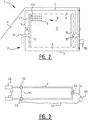
- Figure 1 shows an embodiment of a system 1 for storing the electrical energy according to the invention.
- the system comprises an elongate reservoir 2 which is constructed from a base floor 3, a number of upright walls 4 and a roof 5.
- the floor and walls and the roof can be manufactured from any suitable material, for instance concrete.
- the reservoir can be covered with an earth cover layer (a) to conceal the reservoir from view, although this cover layer is not essential to the invention.
- a thermal insulating layer 6 is arranged on the inner side of the walls, roof and base floor. This insulating layer has the function of ensuring that the heat stored in the inner space of the reservoir remains as far as possible inside the reservoir, and as little heat radiation as possible takes place to the surrounding area.
- the insulating layer can be manufactured from any suitable thermally insulating material. In a typical example the insulating layer is composed of porous stone, for instance specially treated furnace slag or the like. The insulation thickness can vary, but in determined examples the insulating layer is about 2 metres thick. If the system is intended to store energy long-term, for instance up to a year, a thicker insulating layer, up to for instance 5 metres thick, will be desirable.
- a large quantity of energy storage material is arranged in the space surrounded by the insulating layers of the reservoir.
- the energy storage material consists particularly of granular material, such as (dry) sand or sand with grit. Pieces of basalt can advantageously also be used as energy storage material, particularly when mixed with crushed stone.
- the material has sufficient heat capacity per m 3 , a reasonable heat conduction and is resistant to high temperatures, such as higher than 500 degrees Celsius. This granular material is used to temporarily store energy in the form of heat therein.
- a system of a large number of tubular transport elements (for instance in the form of transport tubes) is arranged for this purpose in the granular material of the reservoir. These transport tubes are suitable for transporting a heat transport fluid such as water or gas.
- the heat transport fluid is transported through the transport tubes by means of one or more circulating units (not shown), such as one or more pumps, optionally in combination with suitable valve mechanisms for guiding the heat transport fluid through the correct transport tubes at a suitable moment.
- the walls of the transport tubes take a thermally conductive form so that heat can be transferred from the energy storage material to the heat transport fluid or vice versa in simple manner. If the fluid in the heat transport tube is warmer than the surrounding energy storage material, heat is transferred from the fluid to the energy storage material. At this stage heat is stored in the reservoir for later use. At a stage in which the temperature of the energy storage material is higher than that of the fluid in the transport tubes, heat transfer from the energy storage material to the fluid in the transport tubes can take place. Heat can optionally be extracted from the reservoir at this stage. This heat can be absorbed by the fluid and be used to generate electrical energy.
- Figures 1 and 2 show an embodiment in which tube system 8 comprises a large number of rows and columns of parallel transport tubes 9.
- the transport tubes can all have the same dimensions, although variation in dimensions is also possible.
- a supply collecting tube 12 which is connected to first distribution tubes 46, 47, which are connected to transport tubes 9, is provided on the left-hand side of the reservoir.
- Supply collecting tube 12 is connected to a supply tube 14.
- a discharge collecting tube 16 which is connected to second merging tubes 48 is likewise provided on the right-hand side of reservoir 2.
- Merging tubes 48 are connected to the opposite outer ends of transport tubes 9.
- Discharge collecting tube 16 is further connected to a discharge tube 17.
- Discharge tube 17 and supply tube 14 are connected to a steam generator 20.
- Steam generator 20 comprises a housing which encloses a space 21.
- the fluid provides for the creation of steam in space 21.
- This superheated steam will drive steam turbine 31 for the purpose of the electric generator.
- the temperature should not be too high because the tubes generally become less firm at higher temperature and this, combined with pressure which, in the case of water, rapidly increases at certain temperatures, can cause deformation and possibly even breaking of tubes.
- the temperature should however not be too low either because insufficient steam pressure is otherwise produced to drive the turbine in efficient manner.
- a desired temperature range is set depending on the conditions and on the heat transport fluid used, for water for instance a temperature range of 300 to 350°C.
- the temperature can for instance be increased to 500°C, and in some cases even to higher temperatures. It is best to keep the temperature of the heat transfer fluid in this temperature range. If there is a danger of the temperature in the upper housing becoming too high, a flow of the heat transport fluid to one or more of the lower transport tubes will be generated.
- Figure 3 shows a single transport tube with connecting elements 51, 53 and 56.
- Connecting elements 53 and 51 are connected to electric power source 50 via cables 54, 52.
- the direct voltage can in theory be applied directly to the tubes.
- the direct voltage will in practice however usually already be converted into a (higher) alternating voltage at the source, and the electrical energy will be transported to the reservoir as alternating voltage.
- Power supply 50 produces an electric voltage applied over a predetermined resistor length of transport tube 9, wherein a switch is provided for either applying or not applying the voltage.
- One switch can for instance be provided per transport tube, although other options, such as grouping certain transport tubes, are also possible.
- the tube is manufactured from electrically conductive material, this voltage provides for a current through the tube. This current generates heat which will be transferred to the first heat transport fluid and energy storage material 7. Distribution of heat in the energy storage material can for instance be achieved via selectively applying or not applying a voltage over different tubes.
- Figures 4A-4C show different options with which the circulation of the heat transport fluid in the system can be controlled.
- Figure 4A shows the situation in which a number of transport tubes 56-58 is connected to a central tube 55.
- the transport tubes can be opened and closed as desired using respective valve mechanisms 59-61 on the supply side and valve mechanisms 62-64 on the discharge side.
- the corresponding valve mechanisms can be switched on to guide medium from central tube 55 into the respective transport tube. Pump mechanisms can also replace or be added to the valve mechanisms.
- Figure 4B shows another arrangement of transport tubes 67. In this arrangement the heat transport fluid coming from central tube 55 does not return to central tube 55, but the heat transport fluid comes to lie directly in a second central tube 66.
- valve mechanisms 68, 69 whereby the throughflow through the transport tubes can be controlled.
- FIG. 4C shows yet another embodiment of the invention.
- the heat transport fluid coming in via a central tube 70 is distributed via a number of branches 71 over a large number of parallel transport tubes 72.
- the transport tubes can merge again in a central discharge tube.
- Suitable valve mechanisms and/or pump mechanisms for instance valve mechanisms to enable control of the flow of the medium, can also be provided in this embodiment.
- valve mechanisms and pump mechanisms are preferably remotely controllable, for instance by a central control unit 85 ( fig. 2 ), among other reasons because of the high temperatures and the inaccessibility.
- a central control unit 85 fig. 2
- the control unit can decide whether it is useful to allow flow of heat transport fluid through one or more of the transport tubes.
- control unit is embodied such that the flow of the medium through the tube system can be influenced subject to a number of measured temperature values at strategic positions in the system, for instance at a number of positions in the transport tubes.
- the temperature can be brought to a sufficiently high value by direct heating of the heat transport fluid by means of conducting electric current through the transport tube wall and/or by means of heat transfer of the surrounding medium to these selected tubes. If the temperature in the fluid is however in danger of becoming too high, the control unit switches off the supply of fluid from these tubes and supplies fluid from other selected tubes which are not heated directly via current generation. These tubes are heated by heat transfer from the granular storage medium to the tube. In other embodiments the control unit can also provide for mixing of fluid coming from different components of the reservoir in order to keep the temperature of the fluid which is eventually carried to the flow generator within said temperature range.
- the dimensions of the reservoir can vary. To store a large amount of energy use can for instance be made of a reservoir with a length (1) of more than 250 m, a height (h) of more than 30 m and a width (b) of more than 200 m.
- the length of the transport tubes can then for instance amount to about 200 m, and the number of transport tubes is 60,000 or more (for instance in 80 rows/layers of 750 tubes).
Landscapes
- Engineering & Computer Science (AREA)
- Mechanical Engineering (AREA)
- General Engineering & Computer Science (AREA)
- Physics & Mathematics (AREA)
- Thermal Sciences (AREA)
- Chemical & Material Sciences (AREA)
- Combustion & Propulsion (AREA)
- Central Heating Systems (AREA)
- Engine Equipment That Uses Special Cycles (AREA)
Claims (15)
- System zur Speicherung von elektrischer Energie, wobei das System umfasst:- ein Reservoir, das auf dem Boden gebaut ist oder gebaut werden soll;- eine Menge an Energiespeichermaterial, die in dem Reservoir angeordnet ist;- ein System von röhrenförmigen Elementen, die in das Energiespeichermaterial eingebettet sind, wobei die röhrenförmigen Elemente aus wärme- und stromleitendem Material hergestellt sind;- Umwälzeinheit zum Umwälzen eines Wärmeträgerfluids durch die röhrenförmigen Elemente;- eine Heizeinheit, die derart ausgestaltet ist, dass sie elektrische Energie in Wärme umwandelt, um das Wärmeträgerfluid in den röhrenförmigen Elementen zu erhitzen, dadurch gekennzeichnet, dassdie Heizeinheit mehrere Verbindungselemente umfasst, die an einem oder mehreren der röhrenförmigen Elemente angebracht sind und derart ausgestaltet sind, dass sie eines oder mehrere der röhrenförmigen Elemente mit mindestens einer externen elektrischen Energiequelle verbinden, die derart angeordnet ist, dass in einem ersten Betriebsmodus ein elektrischer Strom über eine vorbestimmte Länge des einen oder der mehreren röhrenförmigen Elemente zum Zweck des Erwärmens des einen oder der mehreren röhrenförmigen Elemente geleitet werden kann, und die Wärme von dem einen oder den mehreren röhrenförmigen Elementen auf das Wärmeträgermedium überträgt und Wärme von dem erhitzten Wärmeträgermedium auf das Energiespeichermaterial zu deren Speicherung in diesem Material überträgt.
- System nach Anspruch 1, wobei die Umwälzeinheit derart ausgestaltet ist, dass sie das in dem einen oder den mehreren röhrenförmigen Elementen erwärmte Wärmeträgerfluid über alle röhrenförmigen Elemente mittels Umwälzung verteilt und/oder wobei die röhrenförmigen Elemente in dem Energiespeichermaterial bei im Wesentlichen gleichmäßig verteilten Positionen eingebettet sind.
- System nach einem der vorstehenden Ansprüche, wobei das System ausgebildet ist, um in einem zweiten Betriebsmodus elektrische Energie aus Energie zu erzeugen, die in dem Energiespeichermaterial gespeichert ist, wobei das System vorzugsweise eine elektrische Energieerzeugungseinheit aufweist, die mit dem System der röhrenförmigen Elemente verbunden ist und die derart ausgestaltet ist, dass sie elektrische Energie aus Wärmeträgerfluid erzeugt, das durch das Energiespeichermaterial erwärmt und entlang der elektrischen Energieerzeugungseinheit transportiert wird.
- System nach einem der vorstehenden Ansprüche, das umfasst:- Ventile zum Steuern der Fluidströmung in mindestens mehreren der röhrenförmigen Elemente des Systems der röhrenförmigen Elemente, und/oder wobei die Umwälzeinheit eine oder mehrere Pumpen umfasst, die zum Pumpen des Fluidstroms durch mindestens mehrere der röhrenförmigen Elemente des Systems der röhrenförmigen Elemente ausgestaltet sind.
- System nach einem der vorstehenden Ansprüche, das eine Steuereinheit umfasst, die ausgebildet ist, um unterschiedliche röhrenförmige Elemente selektiv zu erhitzen, wobei die Steuereinheit vorzugsweise derart ausgestaltet ist, dass sie eine gewünschte Energieverteilung in dem Reservoir bereitstellt.
- System nach einem der vorstehenden Ansprüche, das eine Steuereinheit umfasst, die mit der Heizeinheit und vorzugsweise mit Ventilen und/oder Pumpen gekoppelt ist, wobei die Steuereinheit derart ausgestaltet ist, dass sie durch deren Steuerung eine gewünschte Wärmezufuhr zu dem Wärmespeichermaterial als eine Funktion der Position innerhalb des Reservoirs und der Zeit bereitstellt.
- System nach einem der vorstehenden Ansprüche, wobei die Heizeinheit eine Steuereinheit zum selektiven Heizen verschiedener röhrenförmiger Elemente umfasst, wobei die Steuerung vorzugsweise derart ausgestaltet ist, dass sie eine gewünschte Energieverteilung in dem Reservoir bereitstellt, wobei das System vorzugsweise mehrere röhrenförmige Elemente umfasst, die nebeneinander und übereinander angeordnet sind.
- System nach einem der vorstehenden Ansprüche, wobei das System eine große Anzahl von röhrenförmigen Elementen umfasst, die im Wesentlichen gerade sind und/oder sich im Wesentlichen parallel zueinander erstrecken.
- System nach einem der vorstehenden Ansprüche, das derart ausgestaltet ist, dass es zuerst einen Teil des Energiespeichermaterials unter Verwendung ausgewählter röhrenförmiger Elemente auf mindestens eine gewünschte Temperatur erwärmt und dann einen anderen Teil des Energiespeichermaterials erwärmt, vorzugsweise derart ausgestaltet ist, dass es die Erwärmung des anderen Teils des Energiespeichermaterials dadurch realisiert, dass es das Fluids von den röhrenförmigen Elementen in dem Teil des Energiespeichermaterials, der die gewünschte Temperatur erreicht hat, zu röhrenförmigen Elementen in einem anderen Teil des Energiespeichermaterials verlagert, und/oder vorzugsweise derart ausgestaltet ist, dass es die Erwärmung des anderen Teils des Energiespeichermaterials dadurch realisiert, dass es einen elektrischen Strom über die Länge eines oder mehrerer röhrenförmiger Elemente in dem anderen Teil des Energiespeichermaterials anlegt.
- System nach Anspruch 4, das umfasst:- einen Fluidauslass zum Transportieren von relativ heißem Fluid von dem System von röhrenförmigen Elementen zu der elektrischen Energieerzeugungseinheit;- eine Fluidzufuhr zum Zuführen von relativ kaltem Fluid von der elektrischen Energieerzeugungseinheit zu dem System von röhrenförmigen Elementen, wobei die elektrische Energieerzeugungseinheit vorzugsweise eine Dampfturbine umfasst, die einen Generator für Elektrizität antreibt, und/oder wobei die elektrische Energieerzeugungseinheit vorzugsweise einen Dampfgenerator zum Erzeugen von Dampf umfasst, der mit dem Fluidauslass verbunden ist, und wobei der Turbinengenerator derart ausgestaltet ist, dass er elektrische Energie aus dem Dampf erzeugt.
- System nach einem der vorstehenden Ansprüche, wobei das Wärmeträgerfluid eine Flüssigkeit ist, vorzugsweise Wasser in einer Temperatur bis zu einem Maximum von 350 Grad Celsius, vorzugsweise in einem Temperaturbereich zwischen 300 und 350 Grad Celsius, oder wobei das Wärmeträgerfluid ein Gas ist, vorzugsweise Dampf, vorzugsweise mit einer Temperatur von 500 Grad Celsius oder mehr und/oder wobei das Energiespeichermaterial aus einer Menge an körnigem Material, insbesondere einer Menge an Sand, gegebenenfalls mit Grieß, oder aus einer Menge an Basalt mit gebrochenem Basaltstein gebildet wird.
- System nach einem der vorstehenden Ansprüche, bei dem das Reservoir an einer oder mehreren Seiten und vorzugsweise an allen Seiten durch eine Wärmeisolierschicht begrenzt ist, wobei die Isolierschicht vorzugsweise zumindest teilweise aus porösem Stein besteht und/oder wobei die Isolierschicht mindestens 2 Meter dick, vorzugsweise mindestens 4 Meter dick, noch bevorzugter mindestens 6 Meter dick ist.
- System nach einem der vorstehenden Ansprüche, wobei die Anzahl der röhrenförmigen Elemente, die durch elektrischen Strom erwärmt werden können, mehr als 50%, vorzugsweise mehr als 90%, noch mehr bevorzugt 100% der Gesamtanzahl der röhrenförmigen Elemente beträgt.
- Verfahren zum Speichern von Energie mit dem System nach einem der vorstehenden Ansprüche, wobei das Verfahren in einem ersten Betriebsmodus zum Speichern von Energie umfasst:- Leiten von Strom durch eines oder mehrere der röhrenförmigen Elemente zu deren Heizen und dabei zum Heizen des Wärmeträgerfluids, das in den röhrenförmigen Elementen fließt;- Umwälzen des erwärmten Wärmeträgerfluids durch das System von röhrenförmigen Elementen;- Erwärmen des Energiespeichermediums durch Übertragen von Wärme von dem Wärmeträgerfluid auf das Energiespeichermedium über die Rohrwände der röhrenförmigen Elemente.
- Verfahren nach Anspruch 14, wobei das Verfahren in einem zweiten Betriebsmodus zum Extrahieren von Energie umfasst: Erwärmen des Wärmeträgerfluids mit einem erhitzten Teil des Energiespeichermediums und Antreiben eines Generators mit dem erhitzten Wärmeträgerfluid zum Erzeugen von Elektrizität.
Applications Claiming Priority (1)
| Application Number | Priority Date | Filing Date | Title |
|---|---|---|---|
| NL2015295A NL2015295B1 (nl) | 2015-08-12 | 2015-08-12 | Systeem voor het opslaan van elektrische energie. |
Publications (2)
| Publication Number | Publication Date |
|---|---|
| EP3130875A1 EP3130875A1 (de) | 2017-02-15 |
| EP3130875B1 true EP3130875B1 (de) | 2018-10-17 |
Family
ID=55273462
Family Applications (1)
| Application Number | Title | Priority Date | Filing Date |
|---|---|---|---|
| EP16183807.3A Active EP3130875B1 (de) | 2015-08-12 | 2016-08-11 | System für speicherung von elektrischer energie |
Country Status (2)
| Country | Link |
|---|---|
| EP (1) | EP3130875B1 (de) |
| NL (1) | NL2015295B1 (de) |
Families Citing this family (2)
| Publication number | Priority date | Publication date | Assignee | Title |
|---|---|---|---|---|
| MX2023003158A (es) * | 2020-09-21 | 2023-08-03 | Ooxoj Gmbh | Dispositivo para recibir, almacenar y liberar energia termica. |
| WO2025149216A1 (en) | 2024-01-09 | 2025-07-17 | Tata Steel Ijmuiden B.V. | Concrete having improved heat resistance |
Family Cites Families (3)
| Publication number | Priority date | Publication date | Assignee | Title |
|---|---|---|---|---|
| US5384489A (en) * | 1994-02-07 | 1995-01-24 | Bellac; Alphonse H. | Wind-powered electricity generating system including wind energy storage |
| EP1577548A1 (de) * | 2004-03-16 | 2005-09-21 | Abb Research Ltd. | Vorrichtung und Verfahren zur Speicherung thermischer Energie und Erzeugung von Elektrizität |
| EP2101051A1 (de) * | 2008-03-12 | 2009-09-16 | Siemens Aktiengesellschaft | Speicherung elektrischer Energie mit Wärmespeicher und Rückverstromung mittels eines thermodynamischen Kreisprozesses |
-
2015
- 2015-08-12 NL NL2015295A patent/NL2015295B1/nl active
-
2016
- 2016-08-11 EP EP16183807.3A patent/EP3130875B1/de active Active
Non-Patent Citations (1)
| Title |
|---|
| None * |
Also Published As
| Publication number | Publication date |
|---|---|
| NL2015295B1 (nl) | 2017-02-28 |
| EP3130875A1 (de) | 2017-02-15 |
Similar Documents
| Publication | Publication Date | Title |
|---|---|---|
| US12366180B2 (en) | Thermal energy storage system with steam generation system including flow control and energy cogeneration | |
| US12018596B2 (en) | Thermal energy storage system coupled with thermal power cycle systems | |
| US9523285B2 (en) | Energy storage systems with medium voltage electrical heat exchangers | |
| KR102724519B1 (ko) | 초-고온 열 에너지 저장 시스템 | |
| KR101676589B1 (ko) | 열 에너지 저장용 배열체를 작동시키는 방법 | |
| US8931276B2 (en) | Hybrid renewable energy system having underground heat storage apparatus | |
| WO2014035453A2 (en) | Power tower - system and method of using air flow generated by geothermal generated heat to drive turbines generators for the generation of electricity | |
| US11656035B2 (en) | Heat storing and heat transfer systems incorporating a secondary chamber selectively moveable into a primary heat storage member | |
| US10145365B2 (en) | Integrated thermal storage, heat exchange, and steam generation | |
| CN103742374A (zh) | 一种聚光太阳能热分布式能源综合利用方法 | |
| EP3130875B1 (de) | System für speicherung von elektrischer energie | |
| AU2010206101C1 (en) | Isaakidis high temperature engineered geothermal systems (EGS) | |
| WO2013037045A1 (en) | Thermal energy storage system with input liquid kept above 650°c | |
| WO2015097646A1 (en) | A system for converting thermal energy into electrical energy | |
| RU2254523C1 (ru) | Гелиоветровой водонагреватель | |
| WO2026075556A1 (en) | A thermal storage unit | |
| US20260009594A1 (en) | Thermal energy storage system using a mechanical apparatus for electric power modulation | |
| KR101089958B1 (ko) | 자연복사열을 이용한 발전시스템 | |
| KR20070022679A (ko) | 열 에너지를 저장하는 방법 및 장치 | |
| CN113518890A (zh) | 用于储存能量的装置 | |
| CN118896507A (zh) | 沙子储热系统和沙子储热工艺 |
Legal Events
| Date | Code | Title | Description |
|---|---|---|---|
| PUAI | Public reference made under article 153(3) epc to a published international application that has entered the european phase |
Free format text: ORIGINAL CODE: 0009012 |
|
| STAA | Information on the status of an ep patent application or granted ep patent |
Free format text: STATUS: THE APPLICATION HAS BEEN PUBLISHED |
|
| AK | Designated contracting states |
Kind code of ref document: A1 Designated state(s): AL AT BE BG CH CY CZ DE DK EE ES FI FR GB GR HR HU IE IS IT LI LT LU LV MC MK MT NL NO PL PT RO RS SE SI SK SM TR |
|
| AX | Request for extension of the european patent |
Extension state: BA ME |
|
| STAA | Information on the status of an ep patent application or granted ep patent |
Free format text: STATUS: REQUEST FOR EXAMINATION WAS MADE |
|
| 17P | Request for examination filed |
Effective date: 20170814 |
|
| RBV | Designated contracting states (corrected) |
Designated state(s): AL AT BE BG CH CY CZ DE DK EE ES FI FR GB GR HR HU IE IS IT LI LT LU LV MC MK MT NL NO PL PT RO RS SE SI SK SM TR |
|
| GRAP | Despatch of communication of intention to grant a patent |
Free format text: ORIGINAL CODE: EPIDOSNIGR1 |
|
| STAA | Information on the status of an ep patent application or granted ep patent |
Free format text: STATUS: GRANT OF PATENT IS INTENDED |
|
| INTG | Intention to grant announced |
Effective date: 20180109 |
|
| GRAS | Grant fee paid |
Free format text: ORIGINAL CODE: EPIDOSNIGR3 |
|
| GRAJ | Information related to disapproval of communication of intention to grant by the applicant or resumption of examination proceedings by the epo deleted |
Free format text: ORIGINAL CODE: EPIDOSDIGR1 |
|
| GRAL | Information related to payment of fee for publishing/printing deleted |
Free format text: ORIGINAL CODE: EPIDOSDIGR3 |
|
| STAA | Information on the status of an ep patent application or granted ep patent |
Free format text: STATUS: REQUEST FOR EXAMINATION WAS MADE |
|
| INTC | Intention to grant announced (deleted) | ||
| GRAR | Information related to intention to grant a patent recorded |
Free format text: ORIGINAL CODE: EPIDOSNIGR71 |
|
| STAA | Information on the status of an ep patent application or granted ep patent |
Free format text: STATUS: GRANT OF PATENT IS INTENDED |
|
| INTG | Intention to grant announced |
Effective date: 20180718 |
|
| GRAA | (expected) grant |
Free format text: ORIGINAL CODE: 0009210 |
|
| STAA | Information on the status of an ep patent application or granted ep patent |
Free format text: STATUS: THE PATENT HAS BEEN GRANTED |
|
| AK | Designated contracting states |
Kind code of ref document: B1 Designated state(s): AL AT BE BG CH CY CZ DE DK EE ES FI FR GB GR HR HU IE IS IT LI LT LU LV MC MK MT NL NO PL PT RO RS SE SI SK SM TR |
|
| REG | Reference to a national code |
Ref country code: GB Ref legal event code: FG4D |
|
| REG | Reference to a national code |
Ref country code: CH Ref legal event code: EP |
|
| REG | Reference to a national code |
Ref country code: IE Ref legal event code: FG4D |
|
| REG | Reference to a national code |
Ref country code: DE Ref legal event code: R096 Ref document number: 602016006461 Country of ref document: DE Ref country code: AT Ref legal event code: REF Ref document number: 1054564 Country of ref document: AT Kind code of ref document: T Effective date: 20181115 |
|
| REG | Reference to a national code |
Ref country code: NL Ref legal event code: MP Effective date: 20181017 |
|
| REG | Reference to a national code |
Ref country code: LT Ref legal event code: MG4D |
|
| REG | Reference to a national code |
Ref country code: AT Ref legal event code: MK05 Ref document number: 1054564 Country of ref document: AT Kind code of ref document: T Effective date: 20181017 |
|
| PG25 | Lapsed in a contracting state [announced via postgrant information from national office to epo] |
Ref country code: NL Free format text: LAPSE BECAUSE OF FAILURE TO SUBMIT A TRANSLATION OF THE DESCRIPTION OR TO PAY THE FEE WITHIN THE PRESCRIBED TIME-LIMIT Effective date: 20181017 |
|
| PG25 | Lapsed in a contracting state [announced via postgrant information from national office to epo] |
Ref country code: BG Free format text: LAPSE BECAUSE OF FAILURE TO SUBMIT A TRANSLATION OF THE DESCRIPTION OR TO PAY THE FEE WITHIN THE PRESCRIBED TIME-LIMIT Effective date: 20190117 Ref country code: PL Free format text: LAPSE BECAUSE OF FAILURE TO SUBMIT A TRANSLATION OF THE DESCRIPTION OR TO PAY THE FEE WITHIN THE PRESCRIBED TIME-LIMIT Effective date: 20181017 Ref country code: LT Free format text: LAPSE BECAUSE OF FAILURE TO SUBMIT A TRANSLATION OF THE DESCRIPTION OR TO PAY THE FEE WITHIN THE PRESCRIBED TIME-LIMIT Effective date: 20181017 Ref country code: FI Free format text: LAPSE BECAUSE OF FAILURE TO SUBMIT A TRANSLATION OF THE DESCRIPTION OR TO PAY THE FEE WITHIN THE PRESCRIBED TIME-LIMIT Effective date: 20181017 Ref country code: LV Free format text: LAPSE BECAUSE OF FAILURE TO SUBMIT A TRANSLATION OF THE DESCRIPTION OR TO PAY THE FEE WITHIN THE PRESCRIBED TIME-LIMIT Effective date: 20181017 Ref country code: HR Free format text: LAPSE BECAUSE OF FAILURE TO SUBMIT A TRANSLATION OF THE DESCRIPTION OR TO PAY THE FEE WITHIN THE PRESCRIBED TIME-LIMIT Effective date: 20181017 Ref country code: ES Free format text: LAPSE BECAUSE OF FAILURE TO SUBMIT A TRANSLATION OF THE DESCRIPTION OR TO PAY THE FEE WITHIN THE PRESCRIBED TIME-LIMIT Effective date: 20181017 Ref country code: AT Free format text: LAPSE BECAUSE OF FAILURE TO SUBMIT A TRANSLATION OF THE DESCRIPTION OR TO PAY THE FEE WITHIN THE PRESCRIBED TIME-LIMIT Effective date: 20181017 Ref country code: IS Free format text: LAPSE BECAUSE OF FAILURE TO SUBMIT A TRANSLATION OF THE DESCRIPTION OR TO PAY THE FEE WITHIN THE PRESCRIBED TIME-LIMIT Effective date: 20190217 Ref country code: NO Free format text: LAPSE BECAUSE OF FAILURE TO SUBMIT A TRANSLATION OF THE DESCRIPTION OR TO PAY THE FEE WITHIN THE PRESCRIBED TIME-LIMIT Effective date: 20190117 |
|
| PG25 | Lapsed in a contracting state [announced via postgrant information from national office to epo] |
Ref country code: PT Free format text: LAPSE BECAUSE OF FAILURE TO SUBMIT A TRANSLATION OF THE DESCRIPTION OR TO PAY THE FEE WITHIN THE PRESCRIBED TIME-LIMIT Effective date: 20190217 Ref country code: GR Free format text: LAPSE BECAUSE OF FAILURE TO SUBMIT A TRANSLATION OF THE DESCRIPTION OR TO PAY THE FEE WITHIN THE PRESCRIBED TIME-LIMIT Effective date: 20190118 Ref country code: SE Free format text: LAPSE BECAUSE OF FAILURE TO SUBMIT A TRANSLATION OF THE DESCRIPTION OR TO PAY THE FEE WITHIN THE PRESCRIBED TIME-LIMIT Effective date: 20181017 Ref country code: RS Free format text: LAPSE BECAUSE OF FAILURE TO SUBMIT A TRANSLATION OF THE DESCRIPTION OR TO PAY THE FEE WITHIN THE PRESCRIBED TIME-LIMIT Effective date: 20181017 Ref country code: AL Free format text: LAPSE BECAUSE OF FAILURE TO SUBMIT A TRANSLATION OF THE DESCRIPTION OR TO PAY THE FEE WITHIN THE PRESCRIBED TIME-LIMIT Effective date: 20181017 |
|
| REG | Reference to a national code |
Ref country code: DE Ref legal event code: R097 Ref document number: 602016006461 Country of ref document: DE |
|
| PG25 | Lapsed in a contracting state [announced via postgrant information from national office to epo] |
Ref country code: DK Free format text: LAPSE BECAUSE OF FAILURE TO SUBMIT A TRANSLATION OF THE DESCRIPTION OR TO PAY THE FEE WITHIN THE PRESCRIBED TIME-LIMIT Effective date: 20181017 Ref country code: CZ Free format text: LAPSE BECAUSE OF FAILURE TO SUBMIT A TRANSLATION OF THE DESCRIPTION OR TO PAY THE FEE WITHIN THE PRESCRIBED TIME-LIMIT Effective date: 20181017 Ref country code: IT Free format text: LAPSE BECAUSE OF FAILURE TO SUBMIT A TRANSLATION OF THE DESCRIPTION OR TO PAY THE FEE WITHIN THE PRESCRIBED TIME-LIMIT Effective date: 20181017 |
|
| PLBE | No opposition filed within time limit |
Free format text: ORIGINAL CODE: 0009261 |
|
| STAA | Information on the status of an ep patent application or granted ep patent |
Free format text: STATUS: NO OPPOSITION FILED WITHIN TIME LIMIT |
|
| PG25 | Lapsed in a contracting state [announced via postgrant information from national office to epo] |
Ref country code: SK Free format text: LAPSE BECAUSE OF FAILURE TO SUBMIT A TRANSLATION OF THE DESCRIPTION OR TO PAY THE FEE WITHIN THE PRESCRIBED TIME-LIMIT Effective date: 20181017 Ref country code: SM Free format text: LAPSE BECAUSE OF FAILURE TO SUBMIT A TRANSLATION OF THE DESCRIPTION OR TO PAY THE FEE WITHIN THE PRESCRIBED TIME-LIMIT Effective date: 20181017 Ref country code: EE Free format text: LAPSE BECAUSE OF FAILURE TO SUBMIT A TRANSLATION OF THE DESCRIPTION OR TO PAY THE FEE WITHIN THE PRESCRIBED TIME-LIMIT Effective date: 20181017 Ref country code: RO Free format text: LAPSE BECAUSE OF FAILURE TO SUBMIT A TRANSLATION OF THE DESCRIPTION OR TO PAY THE FEE WITHIN THE PRESCRIBED TIME-LIMIT Effective date: 20181017 |
|
| 26N | No opposition filed |
Effective date: 20190718 |
|
| PG25 | Lapsed in a contracting state [announced via postgrant information from national office to epo] |
Ref country code: SI Free format text: LAPSE BECAUSE OF FAILURE TO SUBMIT A TRANSLATION OF THE DESCRIPTION OR TO PAY THE FEE WITHIN THE PRESCRIBED TIME-LIMIT Effective date: 20181017 |
|
| PG25 | Lapsed in a contracting state [announced via postgrant information from national office to epo] |
Ref country code: TR Free format text: LAPSE BECAUSE OF FAILURE TO SUBMIT A TRANSLATION OF THE DESCRIPTION OR TO PAY THE FEE WITHIN THE PRESCRIBED TIME-LIMIT Effective date: 20181017 |
|
| PG25 | Lapsed in a contracting state [announced via postgrant information from national office to epo] |
Ref country code: MC Free format text: LAPSE BECAUSE OF FAILURE TO SUBMIT A TRANSLATION OF THE DESCRIPTION OR TO PAY THE FEE WITHIN THE PRESCRIBED TIME-LIMIT Effective date: 20181017 Ref country code: LI Free format text: LAPSE BECAUSE OF NON-PAYMENT OF DUE FEES Effective date: 20190831 Ref country code: LU Free format text: LAPSE BECAUSE OF NON-PAYMENT OF DUE FEES Effective date: 20190811 Ref country code: CH Free format text: LAPSE BECAUSE OF NON-PAYMENT OF DUE FEES Effective date: 20190831 |
|
| PG25 | Lapsed in a contracting state [announced via postgrant information from national office to epo] |
Ref country code: IE Free format text: LAPSE BECAUSE OF NON-PAYMENT OF DUE FEES Effective date: 20190811 |
|
| PG25 | Lapsed in a contracting state [announced via postgrant information from national office to epo] |
Ref country code: CY Free format text: LAPSE BECAUSE OF FAILURE TO SUBMIT A TRANSLATION OF THE DESCRIPTION OR TO PAY THE FEE WITHIN THE PRESCRIBED TIME-LIMIT Effective date: 20181017 |
|
| PG25 | Lapsed in a contracting state [announced via postgrant information from national office to epo] |
Ref country code: MT Free format text: LAPSE BECAUSE OF FAILURE TO SUBMIT A TRANSLATION OF THE DESCRIPTION OR TO PAY THE FEE WITHIN THE PRESCRIBED TIME-LIMIT Effective date: 20181017 Ref country code: HU Free format text: LAPSE BECAUSE OF FAILURE TO SUBMIT A TRANSLATION OF THE DESCRIPTION OR TO PAY THE FEE WITHIN THE PRESCRIBED TIME-LIMIT; INVALID AB INITIO Effective date: 20160811 |
|
| PG25 | Lapsed in a contracting state [announced via postgrant information from national office to epo] |
Ref country code: MK Free format text: LAPSE BECAUSE OF FAILURE TO SUBMIT A TRANSLATION OF THE DESCRIPTION OR TO PAY THE FEE WITHIN THE PRESCRIBED TIME-LIMIT Effective date: 20181017 |
|
| P01 | Opt-out of the competence of the unified patent court (upc) registered |
Effective date: 20230703 |
|
| PGFP | Annual fee paid to national office [announced via postgrant information from national office to epo] |
Ref country code: DE Payment date: 20250827 Year of fee payment: 10 |
|
| PGFP | Annual fee paid to national office [announced via postgrant information from national office to epo] |
Ref country code: BE Payment date: 20250827 Year of fee payment: 10 Ref country code: GB Payment date: 20250827 Year of fee payment: 10 |
|
| PGFP | Annual fee paid to national office [announced via postgrant information from national office to epo] |
Ref country code: FR Payment date: 20250825 Year of fee payment: 10 |