EP3130853A1 - A combustion chamber and a combustion chamber segment - Google Patents
A combustion chamber and a combustion chamber segment Download PDFInfo
- Publication number
- EP3130853A1 EP3130853A1 EP16180528.8A EP16180528A EP3130853A1 EP 3130853 A1 EP3130853 A1 EP 3130853A1 EP 16180528 A EP16180528 A EP 16180528A EP 3130853 A1 EP3130853 A1 EP 3130853A1
- Authority
- EP
- European Patent Office
- Prior art keywords
- wall
- combustion chamber
- slot
- extending
- apertures
- Prior art date
- Legal status (The legal status is an assumption and is not a legal conclusion. Google has not performed a legal analysis and makes no representation as to the accuracy of the status listed.)
- Granted
Links
Images






Classifications
-
- F—MECHANICAL ENGINEERING; LIGHTING; HEATING; WEAPONS; BLASTING
- F23—COMBUSTION APPARATUS; COMBUSTION PROCESSES
- F23R—GENERATING COMBUSTION PRODUCTS OF HIGH PRESSURE OR HIGH VELOCITY, e.g. GAS-TURBINE COMBUSTION CHAMBERS
- F23R3/00—Continuous combustion chambers using liquid or gaseous fuel
- F23R3/002—Wall structures
-
- F—MECHANICAL ENGINEERING; LIGHTING; HEATING; WEAPONS; BLASTING
- F02—COMBUSTION ENGINES; HOT-GAS OR COMBUSTION-PRODUCT ENGINE PLANTS
- F02C—GAS-TURBINE PLANTS; AIR INTAKES FOR JET-PROPULSION PLANTS; CONTROLLING FUEL SUPPLY IN AIR-BREATHING JET-PROPULSION PLANTS
- F02C3/00—Gas-turbine plants characterised by the use of combustion products as the working fluid
- F02C3/04—Gas-turbine plants characterised by the use of combustion products as the working fluid having a turbine driving a compressor
-
- F—MECHANICAL ENGINEERING; LIGHTING; HEATING; WEAPONS; BLASTING
- F23—COMBUSTION APPARATUS; COMBUSTION PROCESSES
- F23R—GENERATING COMBUSTION PRODUCTS OF HIGH PRESSURE OR HIGH VELOCITY, e.g. GAS-TURBINE COMBUSTION CHAMBERS
- F23R3/00—Continuous combustion chambers using liquid or gaseous fuel
- F23R3/42—Continuous combustion chambers using liquid or gaseous fuel characterised by the arrangement or form of the flame tubes or combustion chambers
- F23R3/50—Combustion chambers comprising an annular flame tube within an annular casing
-
- F—MECHANICAL ENGINEERING; LIGHTING; HEATING; WEAPONS; BLASTING
- F05—INDEXING SCHEMES RELATING TO ENGINES OR PUMPS IN VARIOUS SUBCLASSES OF CLASSES F01-F04
- F05D—INDEXING SCHEME FOR ASPECTS RELATING TO NON-POSITIVE-DISPLACEMENT MACHINES OR ENGINES, GAS-TURBINES OR JET-PROPULSION PLANTS
- F05D2220/00—Application
- F05D2220/30—Application in turbines
- F05D2220/32—Application in turbines in gas turbines
-
- F—MECHANICAL ENGINEERING; LIGHTING; HEATING; WEAPONS; BLASTING
- F23—COMBUSTION APPARATUS; COMBUSTION PROCESSES
- F23R—GENERATING COMBUSTION PRODUCTS OF HIGH PRESSURE OR HIGH VELOCITY, e.g. GAS-TURBINE COMBUSTION CHAMBERS
- F23R2900/00—Special features of, or arrangements for continuous combustion chambers; Combustion processes therefor
- F23R2900/00005—Preventing fatigue failures or reducing mechanical stress in gas turbine components
-
- F—MECHANICAL ENGINEERING; LIGHTING; HEATING; WEAPONS; BLASTING
- F23—COMBUSTION APPARATUS; COMBUSTION PROCESSES
- F23R—GENERATING COMBUSTION PRODUCTS OF HIGH PRESSURE OR HIGH VELOCITY, e.g. GAS-TURBINE COMBUSTION CHAMBERS
- F23R2900/00—Special features of, or arrangements for continuous combustion chambers; Combustion processes therefor
- F23R2900/03041—Effusion cooled combustion chamber walls or domes
-
- F—MECHANICAL ENGINEERING; LIGHTING; HEATING; WEAPONS; BLASTING
- F23—COMBUSTION APPARATUS; COMBUSTION PROCESSES
- F23R—GENERATING COMBUSTION PRODUCTS OF HIGH PRESSURE OR HIGH VELOCITY, e.g. GAS-TURBINE COMBUSTION CHAMBERS
- F23R2900/00—Special features of, or arrangements for continuous combustion chambers; Combustion processes therefor
- F23R2900/03044—Impingement cooled combustion chamber walls or subassemblies
Definitions
- the present disclosure concerns a combustion chamber and a combustion chamber segment and in particular to a gas turbine engine combustion chamber and a gas turbine engine combustion chamber segment.
- combustion chambers comprise fabricated sheet liners or forged and machined liners.
- More recently developed combustion chambers comprise fabricated sheet outer liners, or forged and machined outer liners, and a plurality of separate tiles each of which is attached to the outer liner.
- the outer liner is provided with an arrangement of cooling holes to provide impingement cooling of the outer surfaces of the tiles and the tiles are provided with cooling holes to provide effusion, or film, cooling of the inner surfaces of the tiles.
- the present disclosure seeks to provide a combustion chamber which reduces, or overcomes, the above mentioned problem.
- a combustion chamber comprising at least one annular wall, the at least one annular wall comprising at least one box like structure, the at least one box like structure comprising an inner wall, an outer wall, an upstream end wall and a downstream end wall, the inner wall being spaced radially from the outer wall, the outer wall having a plurality of apertures for the supply of coolant into the box like structure, the inner wall, the outer wall, the upstream end wall and the downstream end wall being integral, the upstream end of the at least one annular wall having features to secure the at least one annular wall to an upstream ring structure and a downstream end of the at least one annular wall having features to mount the at least one annular wall on a downstream ring structure, the inner wall having at least one slot extending through the full thickness of the inner wall to accommodate differential thermal expansion between the inner wall and the outer wall.
- the at least one annular wall may comprise a plurality of combustion chamber segments, each combustion chamber segment extending the full length of the at least one annular wall, each combustion chamber segment comprising a box like structure, the box like structure comprising a frame structure, an inner wall and an outer wall, the inner wall being spaced radially from the outer wall, the outer wall having a plurality of apertures for the supply of coolant into the box like structure, the frame structure, the inner wall and the outer wall being integral, the upstream end of each combustion chamber segment having features to secure the combustion chamber segment to the upstream ring structure and the downstream end of each combustion chamber segment having features to mount the combustion chamber segment on the downstream ring structure, the inner wall of each combustion chamber segment having at least one slot extending through the full thickness of the inner wall to accommodate differential thermal expansion between the inner wall and the outer wall.
- the box like structure of the combustion chamber segment may have a first end wall extending from a first end of the outer wall to a first end of the inner wall, a second end wall extending from a second, opposite, end of the outer wall to a second, opposite, end of the inner wall, a first edge wall extending from a first edge of the outer wall to a first edge of the inner wall, a second edge wall extending from a second, opposite, edge of the outer wall to a second, opposite, edge of the inner wall to form the box like structure.
- a combustion chamber segment extending the full length of the combustion chamber
- the combustion chamber segment comprising a box like structure, the box like structure comprising a frame structure, an inner wall and an outer wall, the inner wall being spaced from the outer wall, the outer wall having a plurality of apertures for the supply of coolant into the box like structure, the frame structure, the inner wall and the outer wall being integral, the upstream end of the combustion chamber segment having features to secure the combustion chamber segment to an upstream ring structure and a downstream end of the combustion chamber segment having features to mount the combustion chamber segment on a downstream ring structure, the inner wall having at least one slot extending through the full thickness of the inner wall to accommodate differential thermal expansion between the inner wall and the outer wall.
- the inner wall may have a plurality of slots extending through the full thickness of the inner wall to accommodate differential thermal expansion between the inner wall and the outer wall.
- the at least one annular wall may have a plurality of circumferentially spaced dilution apertures extending there-through and each slot may extend between two adjacent dilution apertures. Each slot may extend with axial and circumferential components between the two adjacent dilution apertures. Each slot may comprise a first portion which extends with axial and circumferential components from the first dilution aperture and a second portion which extends with axial and circumferential components from the first portion to the second dilution aperture. Each slot may extend sinusoidally between the two adjacent dilution apertures.
- the plurality of slots and dilution apertures may be arranged to form a loop extending through the full thickness of the inner wall to accommodate differential thermal expansion between the inner wall and the outer wall.
- the slot may be arranged to form a loop extending through the full thickness of the inner wall to accommodate differential thermal expansion between the inner wall and the outer wall.
- At least one of the surfaces of the at least one slot may be arranged at an angle of up to 60° to the surface of the inner wall.
- the at least one surface of the at least one slot may be arranged at an angle of between 10° and 60° to the surface of the inner wall.
- the at least one surface of the at least one slot may be arranged at an angle of between 10° and 50° to the surface of the inner wall.
- the at least one surface of the at least one slot may be arranged at an angle of between 10° and 40° to the surface of the inner wall.
- the at least one surface of the at least one slot may be arranged at an angle of between 10° and 30° to the surface of the inner wall.
- the at least one surface of the at least one slot may be arranged at an angle of 15° to the surface of the inner wall.
- the at least one surface of the at least one slot may be arranged at an angle of 25° to the surface of the inner wall.
- Both surfaces of the at least one slot may be arranged at an angle of up to 60° to the surface of the inner wall. Both surfaces of the at least one slot may be arranged at an angle of between 10° and 60° to the surface of the inner wall. Both surfaces of the at least one slot may be arranged at an angle of between 10° and 50° to the surface of the inner wall. Both surfaces of the at least one slot may be arranged at an angle of between 10° and 40° to the surface of the inner wall. Both surfaces of the at least one slot may be arranged at an angle of between 10° and 30° to the surface of the inner wall. Both surfaces of the at least one slot may be arranged at an angle of 15° to the surface of the inner wall.
- Both surfaces of the at least one slot may be arranged at an angle of 25° to the surface of the inner wall.
- the surfaces of the slot may be parallel. Both surfaces of the slot may be arranged at an angle to the inner surface of the inner wall and the outer surface of the inner wall.
- the slot may be defined between a downstream portion and an upstream portion of the inner wall.
- the slot may be defined between two parallel surfaces, the surfaces being arranged at an angle to the inner surface of the inner wall and at an angle to the outer surface of the inner wall.
- the slot may intersect the inner surface of the inner wall at a position downstream of the position at which the slot intersects the outer surface of the inner wall.
- the parallel surfaces may be arranged on upstream and downstream portions of the inner wall.
- the downstream end of the upstream portion may have a surface being arranged at an angle to the inner surface of the inner wall and at an angle to the outer surface of the inner wall and the upstream end of the downstream portion having a surface arranged at an angle to the inner surface of the inner wall and at an angle to the outer surface of the inner wall.
- the downstream end of the upstream portion may have a first surface portion extending perpendicularly from the inner surface of the inner wall, a second portion extending parallel to the inner surface and the outer surface of the inner wall and a third portion extending perpendicularly to the outer surface of the inner wall, the upstream end of the downstream portion may have a first portion extending at an angle to the inner surface of the inner wall, a second portion extending parallel to the inner surface and the outer surface of the inner wall and a third portion extending perpendicularly to the outer surface of the inner wall.
- the box like structure of the combustion chamber segment may have a first end wall extending from a first end of the outer wall to a first end of the inner wall, a second end wall extending from a second, opposite, end of the outer wall to a second, opposite, end of the inner wall, a first edge wall extending from a first edge of the outer wall to a first edge of the inner wall, a second edge wall extending from a second, opposite, edge of the outer wall to a second, opposite, edge of the inner wall to form the box like structure.
- a plurality of members may be secured to and interconnect the inner wall and the outer wall.
- the members may be integral with the inner wall and the outer wall.
- a cellular structure may be secured to and interconnect the inner wall and the outer wall.
- the cellular structure may be integral with the inner wall and the outer wall.
- the at least one annular wall may be an annular wall of a tubular combustion chamber.
- the at least one annular wall may be a radially inner annular wall of an annular combustion chamber.
- the at least one annular wall may be a radially outer annular wall of an annular combustion chamber.
- the combustion chamber may be a gas turbine engine combustion chamber.
- a gas turbine engine is generally indicated at 10, having a principal and rotational axis 11.
- the engine 10 comprises, in axial flow series, an air intake 12, a propulsive fan 13, an intermediate pressure compressor 14, a high-pressure compressor 15, combustion equipment 16, a high-pressure turbine 17, and intermediate pressure turbine 18, a low-pressure turbine 19 and an exhaust nozzle 20.
- a nacelle 21 generally surrounds the engine 10 and defines both the intake 12 and the exhaust nozzle 20.
- the gas turbine engine 10 works in the conventional manner so that air entering the intake 12 is accelerated by the fan 13 to produce two air flows: a first air flow into the intermediate pressure compressor 14 and a second air flow which passes through a bypass duct 22 to provide propulsive thrust.
- the intermediate pressure compressor 14 compresses the air flow directed into it before delivering that air to the high pressure compressor 15 where further compression takes place.
- the compressed air exhausted from the high-pressure compressor 15 is directed into the combustion equipment 16 where it is mixed with fuel and the mixture combusted.
- the resultant hot combustion products then expand through, and thereby drive the high, intermediate and low-pressure turbines 17, 18, 19 before being exhausted through the nozzle 20 to provide additional propulsive thrust.
- the high 17, intermediate 18 and low 19 pressure turbines drive respectively the high pressure compressor 15, intermediate pressure compressor 14 and fan 13, each by suitable interconnecting shaft.
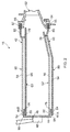
- the combustion chamber 16 is an annular combustion chamber and comprises a radially inner annular wall structure 40, a radially outer annular wall structure 42 and an upstream end wall structure 44.
- the upstream end of the radially inner annular wall structure 40 is secured to the upstream end wall structure 44 and the upstream end of the radially outer annular wall structure 42 is secured to the upstream end wall structure 44.
- the upstream end wall structure 44 has a plurality of circumferentially spaced apertures 46 and each aperture 46 has a respective one of a plurality of fuel injectors 48 located therein.
- the fuel injectors 48 are arranged to supply fuel into the annular combustion chamber 16 during operation of the gas turbine engine 10.
- a plurality of circumferentially arranged turbine nozzle guide vanes 52 are positioned axially downstream of the combustion chamber 16 and arranged to direct the hot gases from the combustion chamber 16 into the high pressure turbine 17.
- the radially inner ends of the turbine nozzle guide vanes 52 are secured to a radially inner discharge nozzle 54 and the radially outer ends of the turbine nozzle guide vanes 52 are secured to a radially outer discharge nozzle 56.
- the radially inner discharge nozzle 54 forms a radially inner downstream ring structure and the radially outer discharge nozzle 56 forms a radially outer downstream ring structure.
- the upstream end wall structure 44 has an inner annular flange 44A extending in an axially downstream direction therefrom and an outer annular flange 44B extending in an axially downstream direction therefrom.
- the upstream end wall structure 44 forms a radially inner upstream ring structure and a radially outer upstream ring structure.
- the radially inner annular wall structure 40 of the annular combustion chamber 16 and the radially outer annular wall structure 42 of the annular combustion chamber 16 comprise a plurality of circumferentially arranged combustion chamber segments 58 and 60 respectively. It is to be noted that the combustion chamber segments 58, 60 extend the full axial, longitudinal, length of the combustion chamber 16.
- combustion chamber segments 58 and 60 of the radially inner and radially outer annular wall structures 40 and 42 of the annular combustion chamber 16 are clearly shown in Figure 3 .
- Other suitable numbers of combustion chamber segments 58 and 60 may be used, e.g. two, three, four, five, six, eight or twelve, and the number of combustion chamber segments 58 may be the same as or different to the number of combustion chamber segments 60. It is preferred that each of the combustion chamber segments extends through the same angle, but it may be possible to arrange the combustion chamber segments to extend through different angles.
- Each combustion chamber segment 58 and 60 comprises a box like structure 62 including an outer wall 64 and an inner wall 66 spaced from the outer wall 64.
- the outer wall 64 and the inner wall 66 are arcuate.
- Figures 4 to 8 show a combustion chamber segment 58 of the radially inner annular wall structure 40.
- the outer wall 64 has a plurality of apertures 69 for the supply of coolant into the box like structure 62 and the inner wall 66 has a plurality of apertures 67 for the supply of coolant out of the box like structure 62.
- a first edge 68 of the box like structure 62 has a first hook 70 extending from the outer wall 64 and away from the inner wall 66.
- the first hook 70 extends at least a portion of the axial, longitudinal, length of the box like structure 62 and the first hook 70 is arranged at a first radial distance from the outer wall 64.
- a second edge 72 of the box like structure 62 has a second hook 74 extending from the outer wall 64 and away from the inner wall 66.
- the second hook 74 extends at least a portion of the axial, longitudinal, length of the box like structure 62, the second hook 74 is arranged at a second radial distance from the outer wall 64 and the second radial distance is greater than the first radial distance.
- the first hook 70 of each combustion chamber segment 58, 60 engages the outer wall 64 at the second edge 72 of an adjacent combustion chamber segment 58, 60 and the second hook 74 of each combustion chamber segment 58, 60 engages the first hook 70 of an adjacent combustion chamber segment 58, 60 to form a seal and to distribute loads between the adjacent combustion chamber segments 58, 60 and to maintain a circular profile, shape, for the radially inner, or radially outer, annular wall structure 40 and 42 of the annular combustion chamber 16, e.g. to prevent dislocation of the combustion chamber segments 58, 60.
- first hook 70 of each combustion chamber segment 58, 60 contacts, abuts, or is in close proximity to the surface of the outer wall 64 at the second edge 72 of the adjacent combustion chamber segment 58, 60 and the second hook 74 of each combustion chamber segment 58, 60 contacts, abuts, or is in close proximity to the surface of the first hook 70 at the first edge 68 of the adjacent combustion chamber segment 58, 60.
- the first hook 70 of each combustion chamber segment 60 is arranged radially outwardly of the outer wall 64 at the second edge 72 of the adjacent combustion chamber segment 60 and the second hook 74 of each combustion chamber 60 is arranged radially outwardly of the first hook 70 at the first edge 68 of the adjacent combustion chamber segment 60.
- first hook 70 of each combustion chamber segment 58 is arranged radially inwardly of the outer wall 64 at the second edge 72 of the adjacent combustion chamber segment 58 and the second hook 74 of each combustion chamber 58 is arranged radially inwardly of the first hook 70 at the first edge 68 of the adjacent combustion chamber segment 58.
- each combustion chamber segment 58, 60 is secured to the upstream ring structure and the downstream end of each combustion chamber segment is mounted on the downstream ring structure.
- the upstream end of each combustion chamber segment 58 is secured to the upstream ring structure, e.g. the upstream end wall structure, 44 and the downstream end of each combustion chamber segment 58 is mounted on the radially inner downstream ring structure, e.g. the radially inner discharge nozzle, 54.
- the upstream end of each combustion chamber segment 60 is secured to the upstream ring structure, e.g. the upstream end wall structure, 44 and the downstream end of each combustion chamber segment 60 is mounted on the radially outer downstream ring structure, e.g. the radially outer discharge nozzle, 56.
- the first hook 70 extends the length of the box like structure 62 between a securing arrangement and a mounting arrangement and the second hook 74 also extends the length of the box like structure 62 between the securing arrangement and the mounting arrangement.
- the securing arrangement and the mounting arrangement are discussed further below.
- first hook may extend the full length of the box like structure and for the second hook to extend the full length of the box like structure.
- first hook may extend only a part of the full length of the box like structure and for the second hook to extend only a part of the full length of the box like structure.
- there may be a plurality of first hooks arranged along the length of the box like structure and for there to be a number of second hooks arranged along the length of the box like structure.
- each combustion chamber segment 58, 60 has a first end wall 76 extending from a first, upstream, end of the outer wall 64 to a first, upstream, end of the inner wall 66, a second end wall 78 extending from a second, downstream and opposite, end of the outer wall 64 to a second, downstream and opposite, end of the inner wall 66, as shown in Figure 2 , a first edge wall 80 extending from a first circumferential edge of the outer wall 64 to a first circumferential edge of the inner wall 66, a second edge wall 82 extending from a second, opposite circumferential, edge of the outer wall 64 to a second, opposite circumferential, edge of the inner wall 66 to form the box like structure 62, as shown in Figures 7 and 8 .
- first and second edges 68 and 72 of the combustion chamber segments 58, 60 are axially profiled so that the at least some of the apertures 67 in the inner wall 66 direct coolant over at least a portion of one of the edges 68 and 72 of the combustion chamber segment 58, 60, as shown in Figures 3 to 6 .
- first and second edges 68 and 72 of each combustion chamber segment 58, 60 has a first portion 68A, 72A extending with a purely axial component, a second portion 68B, 72B extending with axial and circumferential components and a third portion 68C, 72C extending with a purely axial component.
- first and second edges 68 and 72 of each combustion chamber segment 58, 60 are profiled so that the at least some of the apertures 67A in the inner wall 66 near the first edge 68 direct coolant over at least a portion of the second edge 70 of an adjacent combustion chamber segment 58, 60.
- the apertures 67A in the inner wall 66 near the first edge 68 in the first and second portions 68A and 68B of each combustion chamber segment 58, 60 direct coolant in a generally axially downstream direction across the gap between the first edge 68 of the combustion chamber segment 58, 60 and the second edge 72 of the adjacent combustion chamber segment 58, 60 and then over the second and third portions 72B and 72C of the adjacent combustion chamber segment 58, 60.
- first and second edges of the combustion chamber segments may extend with axial and circumferential components or the first and second edges of the combustion chamber segments may be S-shaped or W-shaped.
- each combustion chamber segment 58, 60 comprises a frame 75.
- the frame 75 comprises the first and second end walls 76 and 78 and the first and second edge walls 80 and 82.
- the first and second end walls 76 and 78 and the first and second edge walls 80 and 82 are integral, e.g. one piece.
- each combustion chamber segment 58, 60 is radially thicker, and stiffer, than the outer wall 64 and the inner wall 66 and the first and second end walls 76 and 78 and the first and second edge walls 80 and 82 are thicker axially and thicker circumferentially respectively than the radial thickness of the outer and inner walls 64 and 66 in order to carry loads and interface with adjacent combustion chamber segments 58, 60 and the upstream ring structure and the downstream ring structure.
- the frame 75 of each combustion chamber segment 58, 60 is arranged to carry the structural loads, the thermal loads, surge loads and flameout loads.
- the first hook 70 is provided on the first edge wall 80 and the second hook 74 is provided on the second edge wall 82.
- each combustion chamber segment 58, 60 comprises the frame 75 and portions of the outer and inner walls 64 and 66 extending axially, longitudinally, between the first and second end walls 76 and 78 and extending circumferentially, laterally, between the first and second edge walls 80 and 82 and the box like structure 62 is an integral structure, e.g. one piece structure or a monolithic structure.
- the first, upstream, end of the outer wall 64 of each combustion chamber segment 58, 60 has a flange 84 and the flange 84 has at least one locally thicker region 88, each locally thicker region 88 of the outer wall 64 has an aperture 92 extending there-through.
- the first, upstream, end of the inner wall 66 has a flange 86 and the flange 86 has at least one locally thicker region 90, each locally thicker region 90 of the inner wall 66 has an aperture 94 extending there-through.
- the at least one locally thicker region 88 at the first end of the outer wall 64 is arranged such that the aperture 92 is aligned with the aperture 94 through the corresponding locally thicker region 90 of the inner wall 66 and an annular slot 95 is formed between the flange 84 of the first end of the inner wall 66 and the flange 86 of the first end of the outer wall 66.
- the flange 84 at the first end of the outer wall 64 and the flange 86 at the first end of the inner wall 66 of each combustion chamber segment 58, 60 have a plurality of locally thickened regions 88, 90 respectively and the locally thicker regions 88, 90 are spaced apart circumferentially, laterally, between the first and second edges 68, 70 of the outer and inner walls 64 and 66 of the combustion chamber segments 58, 60.
- the aperture 94 in the at least one, or each, locally thickened region 90 of the inner wall 66 of each combustion chamber segment 58, 60 is threaded.
- Each combustion chamber segment 58, 60 is secured to the upstream end wall structure 44 by one or more bolts 96.
- Each combustion chamber segment 58 is positioned such that the inner annular flange 44A of the upstream end wall structure 44 is located radially between the flanges 84 and 86 at the upstream end of the combustion segment 58 and such that the apertures 92 and 94 in the flanges 84 and 86 are aligned with a corresponding one of a plurality of circumferentially spaced apertures 45A in the flange 44A of the upstream end wall structure 44.
- Bolts are inserted through the aligned apertures 92 and 45A and threaded into the apertures 94 to secure the combustion chamber segment 58 to the upstream end wall structure 44.
- each combustion chamber segment 60 is positioned such that the inner annular flange 44B of the upstream end wall structure 44 is located radially between the flanges 84 and 86 at the upstream end of the combustion segment 60 and such that the apertures 92 and 94 in the flanges 84 and 86 are aligned with a corresponding one of a plurality of circumferentially spaced apertures 45B in the flange 44B of the upstream end wall structure 44.
- Bolts are inserted through the aligned apertures 92 and 45A and threaded into the apertures 94 to secure the combustion chamber segment 60 to the upstream end wall structure 44.
- rivets may be inserted through the aligned apertures 92 and 45A and the apertures 94 to secure the combustion chamber segment 60 to the upstream end wall structure 44.
- the second hook 74 of each combustion chamber segment 58, 60 forms a groove and the first hook 70 forms a tongue.
- the second hook 74 of each combustion chamber segment 58, 60 may form a dovetail shaped groove and the first hook 70 of each combustion chamber segment 58, 60 may form a dovetail shaped tongue.
- Each combustion chamber segment 58 is mounted on the radially inner downstream ring structure, e.g. the radially inner discharge nozzle, 54.
- the second, downstream, end of the outer wall 64 of each combustion chamber segment 58 has a flange 85 and the flange 85 of each combustion chamber segment 58 is positioned in an annular slot 55 formed in the radially inner discharge nozzle 54, as shown in Figure 2 .
- Each combustion chamber segment 60 is mounted on the radially outer downstream ring structure, e.g. the radially outer discharge nozzle, 56.
- each combustion chamber segment 60 has a flange 85 and the flange 85 of each combustion chamber segment 60 is positioned in an annular slot 57 formed in the radially outer discharge nozzle 56, also shown in Figure 2 .
- each combustion chamber segment 58, 60 has at least one dilution aperture 100
- the inner wall 66 of each combustion chamber segment 58, 60 has at least one dilution aperture 102 aligned with the corresponding dilution aperture 100 in the outer wall 64.
- At least one dilution wall 104 extends from the periphery of the corresponding dilution aperture 100 in the outer wall 64 to the periphery of the corresponding dilution aperture 102 in the inner wall 66.
- each combustion chamber segment 58, 60 has at least one dilution chute 106, the at least one dilution chute 106 extends from the inner wall 66 in a radial direction away from the inner wall 66 and the outer wall 66 and each dilution chute 106 is aligned with a corresponding one of the dilution apertures 104 in the inner wall 66, as shown in Figures 4 to 7 .
- combustion chamber 16 is a lean burn combustion chamber the combustion chamber segments 58, 60 are not provided with dilution apertures, dilution walls and dilution chutes.
- the apertures 69 in the outer wall 64 of each combustion chamber segment 58, 60 may be arranged perpendicularly to the surface of the outer wall 64 and the apertures 67 in the inner wall 66 of each combustion chamber segment 58, 60 may be arranged perpendicularly to the surface of the inner wall 66 or at non-perpendicular angle to the surface of the inner wall 66 so that the apertures 69 in the outer wall provide impingement cooling of the inner wall 66 and the apertures 67 in the inner wall 66 provide effusion, or film, cooling of the inner wall 66.
- the apertures 67 in the inner wall 66 of each combustion chamber segment 58, 60 arranged at a non-perpendicular angle to the surface of the inner wall 66 may be angled in a longitudinal, axial, direction.
- the apertures 67 in the inner wall 66 of each combustion chamber segment 58, 60 may have a fan shaped outlet or other suitable shapes of outlets may be used.
- the apertures 69 in the outer wall 64 of each combustion chamber segment may have bell mouth shaped inlets or other suitable shapes of inlets may be used.
- the apertures 69 provide impingement cooling of the inner wall 66.
- each combustion chamber segment 58, 60 may have a plurality of pedestals extending from the inner wall 66 towards the outer wall 64 to provide additional cooling of the inner wall 66.
- the pedestals extending from the inner wall 66 towards the outer wall 64 may extend all the way to the outer wall 64 such that the pedestals, the inner wall 66 and the outer wall 64 are integral, e.g. one piece.
- Each combustion chamber segment 58, 60 may have U shaped effusion cooling apertures extending through the inner wall 66.
- the U shaped effusion cooling apertures in the inner wall 66 of each combustion chamber segment 58, 60 may have a fan shaped outlet.
- the inlets and outlets of the U shaped effusion cooling apertures may be arranged axially, longitudinally, downstream of a U shaped bend on the U shaped effusion cooling aperture.
- each combustion chamber segment 58, 60 may have a cellular structure between the inner wall 66 and the outer wall 66, the cellular structure comprising a plurality of polyhedron shaped chambers defined by a matrix of integral interconnected walls, the polyhedron shaped chambers are arranged in at least two layers between the inner wall 66 and the outer wall 64. At least some of the polyhedron shaped chambers in each layer are fluidly interconnected to at least some of the polyhedron shaped chambers in each adjacent layer by apertures extending through the integral interconnected walls of the polyhedron shaped chambers for the flow of coolant there-between.
- the apertures in the outer wall 64 allow a flow of coolant into the cellular structure and the apertures in the inner wall 66 allow a flow of coolant out of the cellular structure.
- the polyhedron shaped chambers may be parallelogram sided cuboid shaped chambers, square based pyramid shaped chambers, rhombic dodecahedron shaped chambers, elongated dodecahedron shaped chambers, truncated dodecahedron shaped chambers, spherical shaped chambers, spheroid shaped chambers or two types of irregular polyhedron shaped chambers arranged in a Weaire-Phelan structure.
- Spheroid shaped chambers includes elliptical or similar shaped chambers.
- the cellular structure and the box like structure is an integral structure, e.g. a single piece structure, a unitary structure or a monolithic structure.
- the box like structure comprising the frame structure, the inner wall, the outer wall, and the cellular structure is an integral structure, e.g. a single piece structure, a unitary structure or a monolithic structure.
- the box like structure comprising the inner wall, the outer wall, the upstream end wall, the downstream end wall and the cellular structure is an integral structure, e.g. a single piece structure, a unitary structure or a monolithic structure.
- the thickness of the wall of the polyhedron shaped chamber may be in the range of 0.2 to 2mm.
- the distance between the walls of the polyhedron shaped chambers may be in the range of 1 to 4mm.
- each combustion chamber segment 58, 60 has at least one slot 108 extending through the full thickness of the inner wall 66 to accommodate differential thermal expansion between the inner wall 66 and the outer wall 64.
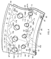
- the inner wall 66 of each combustion chamber segment 58, 60 has a plurality of slots 108A, 108B and 108C extending through the full thickness of the inner wall 66 to accommodate differential thermal expansion between the inner wall 66 and the outer wall 64, as shown in Figure 4 .
- Each slot 108A, 108B and 108C in the inner wall 66 of each combustion chamber segment 58, 60 extends between two dilution apertures 102 in the inner wall 66.
- Each slot 108A, 108B and 108C extends with axial and circumferential components between the two dilution apertures 102 in the inner wall 66.
- Each slot 108A comprises a first portion 109 which extends with axially upstream and circumferential components from the first dilution aperture 102 and a second portion 110 which extends with axially downstream and circumferential components from the first portion 109 to the second dilution aperture 102.
- each slot 108A is V-shaped in the plane of the inner wall 66 and the apex 111 of each V-shaped slot 108A is axially upstream of the ends of the slot 108A.
- Each slot 108B comprises a first portion 112 which extends with axially downstream and circumferential components from the first dilution aperture 102 and a second portion 113 which extends with an axially downstream component from the first portion 112 to the second dilution aperture 102.
- each slot 108B is also V-shaped in the plane of the inner wall 66.
- the slot 108C comprises a plurality of portions 114 and 115 which extend with axial and circumferential components and two portions 118 which extend with axial components from the dilution aperture 102 to the second aperture 102 such that the slot 108C extends sinusoidally, e.g.
- the portions 114 and 115 extend between axially upstream apexes 116 and axially downstream apexes 117.
- the plurality of slots 108A, 108B and 108C and the dilution apertures 102 are arranged to form a loop L extending through the full thickness of the inner wall 66 to accommodate differential thermal expansion between the inner wall 66 and the outer wall 64 of each combustion chamber segment 58, 60.
- Each slot 108A extends between two adjacent dilution apertures 102 in a first row of circumferentially spaced dilution apertures 102.
- Each slot 108B extends between a dilution aperture 102 in the first row of dilution apertures 102 and a dilution aperture 102 in a second row of dilution apertures 102 where the first and second rows of dilution apertures 102 are axially spaced.
- the slot 108C extends between two dilution apertures 102 in the second row of circumferentially spaced dilution apertures 102.
- the small radius may be less than 3mm.
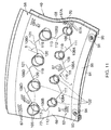
- each combustion chamber segment 58, 60 has a plurality of slots 108A, 108B and 108D extending through the full thickness of the inner wall 66 to accommodate differential thermal expansion between the inner wall 66 and the outer wall 64, as shown in Figure 11 .
- Each slot 108A, 108B and 108D in the inner wall 66 of each combustion chamber segment 58, 60 extends between two dilution apertures 102 in the inner wall 66.
- Each slot 108A, 108B and 108D extends with axial and circumferential components between the two dilution apertures 102 in the inner wall 66.
- Each slot 108A comprises a first portion 109 which extends with axially upstream and circumferential components from the first dilution aperture 102 and a second portion 110 which extends with axially downstream and circumferential components from the first portion 109 to the second dilution aperture 102.
- each slot 108A is V-shaped in the plane of the inner wall 66 and the apex of each V-shaped slot 108A is axially upstream of the ends of the slot 108A.
- Each slot 108B comprises a first portion 112 which extends with axially downstream and circumferential components from the first dilution aperture 102 and a second portion 113 which extends with an axially downstream component from the first portion 112 to the second dilution aperture 102.
- each slot 108B is also V-shaped in the plane of the inner wall 66.
- Each slot 108D comprises a first portion 119 which extends with axially downstream and circumferential components from the first dilution aperture 102 and a second portion 120 which extends with axially upstream and circumferential components from the first portion 119 to the second dilution aperture 102.
- each slot 108D is V-shaped in the plane of the inner wall 66 and the apex 121 of each V-shaped slot 108D is axially downstream of the ends of the slot 108D.
- the plurality of slots 108A, 108B and 108D and the dilution apertures 102 are arranged to form a loop L extending through the full thickness of the inner wall 66 to accommodate differential thermal expansion between the inner wall 66 and the outer wall 64 of each combustion chamber segment 58, 60.
- Each slot 108A extends between two adjacent dilution apertures 102 in a first row of circumferentially spaced dilution apertures 102.
- Each slot 108B extends between a dilution aperture 102 in the first row of dilution apertures 102 and a dilution aperture 102 in a second row of dilution apertures 102 where the first and second rows of dilution apertures 102 are axially spaced.
- Each slot 108D extends between two adjacent dilution apertures 102 in a second row of circumferentially spaced dilution apertures 102.
- the small radius may be less than 3mm.
- the inner wall 66 of the radially inner annular wall structure 40 and the radially outer annular wall structure 42 has at least one slot 108 extending through the full thickness of the inner wall 66 to accommodate differential thermal expansion between the inner wall 66 and the outer wall 64.
- the inner wall 66 of the radially inner annular wall structure 40 and the radially outer annular wall structure 42 has a plurality of slots 108A, 108B and 108C extending through the full thickness of the inner wall 66 to accommodate differential thermal expansion between the inner wall 66 and the outer wall 64, as shown in Figure 12 .
- the radially inner annular wall structure 40 and the radially outer annular wall structure 42 of Figure 12 are different from those in figures 3 to 11 in that the radially inner annular wall structure 40 and the radially outer annular wall structure 42 are circumferentially continuous and do not comprise segments.
- Each slot 108A, 108B and 108C in the inner wall 66 of each combustion chamber segment 58, 60 extends between two dilution apertures 102 in the inner wall 66.
- Each slot 108A, 108B and 108C extends with axial and circumferential components between the two dilution apertures 102 in the inner wall 66.
- Each slot 108A comprises a first portion 109 which extends with axially upstream and circumferential components from the first dilution aperture 102 and a second portion 110 which extends with axially downstream and circumferential components from the first portion 109 to the second dilution aperture 102.
- each slot 108A is V-shaped in the plane of the inner wall 66 and the apex of each V-shaped slot 108A is axially upstream of the ends of the slot 108A.
- Each slot 108B comprises a first portion 112 which extends with axially downstream and circumferential components from the first dilution aperture 102 and a second portion 113 which extends with an axially downstream component from the first portion 112 to the second dilution aperture 102.
- each slot 108B is also V-shaped in the plane of the inner wall 66.
- the slot 108C comprises a plurality of portions 114 and 115 which extend with axial and circumferential components and two portions 118 which extend with axial components from the dilution aperture 102 to the second aperture 102 such that the slot 108C extends sinusoidally, e.g.
- the portions 114 and 115 extend between axially upstream apexes 116 and axially downstream apexes 117.
- the plurality of slots 108A, 108B and 108C and the dilution apertures 102 are arranged to form a loop L extending through the full thickness of the inner wall 66 to accommodate differential thermal expansion between the inner wall 66 and the outer wall 64.
- Each slot 108A extends between two adjacent dilution apertures 102 in a first row of circumferentially spaced dilution apertures 102.
- Each slot 108B extends between a dilution aperture 102 in the first row of dilution apertures 102 and a dilution aperture 102 in a second row of dilution apertures 102 where the first and second rows of dilution apertures 102 are axially spaced.
- the slot 108C extends between two dilution apertures 102 in the second row of circumferentially spaced dilution apertures 102.
- the inner wall 66 of the radially inner annular wall structure 40 and the radially outer annular wall structure 42 has a plurality of circumferentially spaced loops L extending through the full thickness of the inner wall 66 to accommodate differential thermal expansion between the inner wall 66 and the outer wall 64.
- each slot 108A, 108B and 108D there may be a small radius of curvature at the, or each, apex to minimise the risk of any crack initiation due to the change in the angle of the slot 108A, 108B, and/or 108D.
- the small radius may be less than 3mm.
- Figure 9 is a cross-sectional view in a plane containing the axis of the gas turbine engine 10 through a combustion chamber segment 58, 60 showing one arrangement of slot 108.
- the inner wall 66 and the outer wall 64 are connected by pedestals 65 which are integral with the inner wall 66 and the outer wall 64.
- the inner wall 66 has a plurality of apertures 67 extending there-through and in this example the apertures 67 are arranged at an angle to the surface of the inner wall 66 and the outlet of each aperture 67 is positioned downstream of its inlet.
- the outer wall 64 has a plurality of apertures 69 extending there-through and in this example the apertures 69 are arranged perpendicular to the surface of the outer wall 64.
- both surfaces 66C, 66D of the slot 108 are arranged at an angle ⁇ of up to 60° to the surface of the inner wall 66.
- Both surfaces 66C, 66D of the slot 108 may be arranged at an angle ⁇ of between 10° and 60° to the surface of the inner wall 66.
- Both surfaces 66C, 66D of the slot 108 may be arranged at an angle ⁇ of between 10° and 50° to the surface of the inner wall 66.
- Both surfaces 66C, 66D of the slot 108 may be arranged at an angle ⁇ of between 10° and 40° to the surface of the inner wall 66.
- Both surfaces 66C, 66D of the slot may be arranged at an angle ⁇ of between 10° and 30° to the surface of the inner wall 66. Both surfaces 66C, 66D of the slot 108 may be arranged at an angle ⁇ of 15° to the surface of the inner wall 66. Both surfaces 66C, 66D of the slot 108 may be arranged at an angle ⁇ of 25° to the surface of the inner wall 66. Thus, the surfaces 66C, 66D of the slot 108 are parallel. Alternatively, the surfaces 66C, 66D of the slot 108 may be built such that the surfaces diverge from the cold side of the inner wall 66 to the hot side of the inner wall 66 but the surfaces of the slot are parallel in operation. Both surfaces 66C, 66D of the slot 108 are arranged at an angle ⁇ to the inner surface of the inner wall 66 and the outer surface of the inner wall 66.
- the slot 108 is defined between two parallel surfaces 66C, 66D and the surfaces 66C, 66D are arranged at an angle ⁇ to the inner surface of the inner wall 66 and at an angle to the outer surface of the inner wall 66.
- the slot 108 intersects the inner surface of the inner wall 66 at a position downstream of the position at which the slot 108 intersects the outer surface of the inner wall 66.
- the parallel surfaces 66C and 66D are arranged on upstream and downstream portions 66A and 66B respectively of the inner wall 66.
- the surface 66C at the downstream end of the upstream portion 66A is arranged at an angle ⁇ to the inner surface of the inner wall 66 and at an angle ⁇ to the outer surface of the inner wall 66 and the surface 66D at the upstream end of the downstream portion 66B is arranged at an angle ⁇ to the inner surface of the inner wall 66 and at an angle ⁇ to the outer surface of the inner wall 66.
- the apertures 67 and the slot 108 may be arranged at the same angle ⁇ to the surface of the inner wall 66.
- the apertures 67 and the slot 108 may be arranged at different angles to the surface of the inner wall 66 but so that the apertures 67 do not intersect with the slot 108.
- the apertures 67 and the slot 108 may be arranged at different angles to the surface of the inner wall 66 but so that the apertures 67 do intersect with the slot 108.
- the combustion chamber segments 58, 60, the circumferentially continuous radially inner annular wall structure 40 or the circumferentially continuous radially outer annular wall structure 42 are manufactured by additive layer manufacturing.
- the surfaces 66C and 66D of the slot 108 are angled to the build direction to improve the surface finish of the surfaces any poor surface finish is of sufficiently low mechanical integrity so as not to prevent closing of the gap due to differential thermal expansion.
- the upstream end of the downstream portion 66B is supported during the additive layer manufacturing process by the pedestals 65 and thus other support structure is required and thus pedestals 65 are provided at the upstream end of the downstream portion 66B at, or adjacent and downstream of the, position at which the slot 108 intersects the outer surface of the inner wall 66.
- Figure 10 is a cross-sectional view in a plane containing the axis of the gas turbine engine 10 through a combustion chamber segment 158, 160 showing an alternative arrangement of slot 208.
- the inner wall 166 and the outer wall 164 are connected by pedestals 165 which are integral with the inner wall 166 and the outer wall 164.
- the inner wall 166 has a plurality of apertures 167 extending there-through and in this example the apertures 167 are arranged at an angle to the surface of the inner wall 166 and the outlet of each aperture 167 is positioned downstream of its inlet.
- the outer wall 164 has a plurality of apertures 169 extending there-through and in this example the apertures 169 are arranged perpendicular to the surface of the outer wall 164 and the apertures 169 have bell mouth shaped inlets.
- the apertures 169 provide impingement cooling of the inner wall 166.
- the downstream end of the upstream portion 166A has a first surface portion 166C extending perpendicularly from the inner surface of the inner wall 166, a second surface portion 166D extending parallel to the inner surface and the outer surface of the inner wall 166 and a third surface portion 166E extending perpendicularly to the outer surface of the inner wall 166.
- the upstream end of the downstream portion 166B has a first surface portion 166F extending at an angle ⁇ to the inner surface of the inner wall 166, a second surface portion 166G extending parallel to the inner surface and the outer surface of the inner wall 166 and a third surface portion 166H extending perpendicularly to the outer surface of the inner wall 166.
- the upstream end of the downstream portion 166B overlaps, but is spaced from, the downstream end of the upstream portion 166A and the second surface portions 166D and 166G of the upstream and downstream portions 166A and 166B are parallel.
- the surfaces 166F and 166G at the upstream end of the downstream portion 166B of the inner wall 166 taper to an edge 171. This arrangement of slot 208 has reduced leakage compared to slot 108.
- first surface portion 166F of the slot 208 is arranged at an angle ⁇ of up to 60° to the surface of the inner wall 166.
- the first surface portion 166F of the slot 208 may be arranged at an angle ⁇ of between 10° and 60° to the surface of the inner wall 166.
- the first surface portion 166F of the slot 208 may be arranged at an angle ⁇ of between 10° and 50° to the surface of the inner wall 166.
- the first surface portion 166F of the slot 208 may be arranged at an angle ⁇ of between 10° and 40° to the surface of the inner wall 166.
- the first surface portion 166F of the slot 208 may be arranged at an angle ⁇ of between 10° and 30° to the surface of the inner wall 166.
- the first surface portion 166F of the slot 208 may be arranged at an angle ⁇ of 15° to the surface of the inner wall 166 or the first surface portion 166F of the slot 208 may be arranged at an angle ⁇ of 25° to the surface of the inner wall 166.
- the apertures 167 and the slot 208 may be arranged at the same angle ⁇ to the surface of the inner wall 166.
- the apertures 167 and the slot 208 may be arranged at different angles to the surface of the inner wall 166 but so that the apertures 167 do not intersect with the slot 208.
- the apertures 167 and the slot 208 may be arranged at different angles to the surface of the inner wall 166 but so that the apertures 167 do intersect with the slot 208.
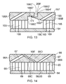
- Figure 13 is a cross-sectional view in a plane containing the axis of the gas turbine engine 10 through a combustion chamber segment 158, 160 showing an alternative arrangement of slot 208'.
- the inner wall 166 and the outer wall 164 are connected by pedestals 165 which are integral with the inner wall 166 and the outer wall 164.
- the inner wall 166 has a plurality of apertures 167 extending there-through and in this example the apertures 167 are arranged at an angle to the surface of the inner wall 166 and the outlet of each aperture 167 is positioned downstream of its inlet.
- the outer wall 164 has a plurality of apertures 169 extending there-through and in this example the apertures 169 are arranged perpendicular to the surface of the outer wall 164 and the apertures 169 have bell mouth shaped inlets.
- the apertures 169 provide impingement cooling of the inner wall 166.
- the arrangement of the slot 208' is similar to that of the slot 208 in figure 10 , but in this example the downstream end of the upstream portion 166A has a first surface portion 166C' extending perpendicularly from the outer surface of the inner wall 166, a second surface portion 166D' extending parallel to the inner surface and the outer surface of the inner wall 166 and a third surface portion 166E' extending perpendicularly to the outer surface of the inner wall 166.
- the upstream end of the downstream portion 166B has a first surface portion 166F' extending at an angle ⁇ to the outer surface of the inner wall 166, a second surface portion 166G' extending parallel to the inner surface and the outer surface of the inner wall 166 and a third surface portion 166H' extending perpendicularly to the inner surface of the inner wall 166.
- the downstream end of the upstream portion 166A overlaps, but is spaced from, the upstream end of the downstream portion 166B and the second surface portions 166D' and 166G' of the upstream and downstream portions 166A and 166B are parallel.
- the surfaces 166F' and 166G' at the upstream end of the downstream portion 166B of the inner wall 166 taper to an edge 171'. This arrangement of slot 208' also has reduced leakage compared to slot 108.
- Figure 14 is a cross-sectional view in a plane containing the axis of the gas turbine engine 10 through a combustion chamber segment 58, 60 showing a further arrangement of slot 108'.
- the slot 108' is substantially the same as that shown in figure 9 but the slot 108' is angled in an upstream direction from the outer surface to the inner surface of the inner wall 66 whereas in figure 9 the slot 108 is angled in a downstream direction from the outer surface to the inner surface of the inner wall 66.
- the combustion chamber segments 58, 60, the circumferentially continuous radially inner annular wall structure 40 or the circumferentially continuous radially outer annular wall structure 42 are manufactured by additive layer manufacturing.
- the upstream end of the downstream portion 166B is supported during the additive layer manufacturing process by the pedestals 165 and thus other support structure is required and thus pedestals 165 are provided at the upstream end of the downstream portion 166B at, or adjacent and downstream of the, position at which the slot 208 intersects the outer surface of the inner wall 166.
- the downstream portion 166B of the inner wall 166 is built by the additive layer manufacturing process from the edge 171 and a frangible feature 173 is provided between the second surface portion 166D of the upstream portion 166 of the inner wall 166 and the edge 171 on the downstream portion 166B of the inner wall 166.
- the frangible feature 173 is constructed such that it will break due to the load imposed by the differential thermal expansion between the inner wall 166 and the outer wall 164 during operation of the combustion chamber 16.
- each combustion chamber segment 58, 60 has a plurality of slots 108A, 108B and 108D extending through the full thickness of the inner wall 66 to accommodate differential thermal expansion between the inner wall 66 and the outer wall 64, as shown in Figure 15 .
- the arrangement in Figure 15 is similar to that in Figure 11 but there are two circumferentially spaced loops L1 and L2.
- the slot, slots, loop or loops provide one or more small gaps in the inner wall 66, 166 of the combustion chamber segments 58, 60 or the circumferentially continuous radially inner annular wall structure 40 or the circumferentially continuous radially outer annular wall structure 42 and the small gap or gaps are able to close to accommodate the greater expansion of the inner wall 66, 166 with respect to the outer wall 64, 164 without transmitting stresses into the combustion chamber segment 58, 60 or the circumferentially continuous radially inner annular wall structure 40 or the circumferentially continuous radially outer annular wall structure 42.
- the gap is large enough to accommodate the differential thermal expansion between the inner wall 66, 166 and the outer wall 64, 164 but yet is small enough to control leakage of coolant through the slot 108, 208 from the space between the inner wall 66, 166 and the outer wall 64, 164.
- the outer wall 64, 164 may expand by up to 0.5mm less than the inner wall 66, 166.
- the portions 109, 110, 112, 114, 115, 119 and 120 of the slots 108A, 108B, 108C and 108D which extend with axial and circumferential components are arranged such that they are arranged at an angle ⁇ relative to the build direction, which is also the axial direction, or longitudinal direction, of the combustion chamber segment 58, 60 or the annular wall.
- the angle ⁇ is up to 60° from the build direction or axial direction or greater than 30° from the circumferential direction.
- the combustion chamber may comprise at least one annular wall, the at least one annular wall comprising at least one box like structure, the at least one box like structure comprising an inner wall, an outer wall, an upstream end wall and a downstream end wall, the inner wall being spaced radially from the outer wall, the outer wall having a plurality of apertures for the supply of coolant into the box like structure, the inner wall, the outer wall, the upstream end wall and the downstream end wall being integral, the upstream end of the at least one annular wall having features to secure the at least one annular wall to an upstream ring structure and a downstream end of the at least one annular wall having features to mount the at least one annular wall on a downstream ring structure, the inner wall having at least one slot extending through the full thickness of the inner wall to accommodate differential thermal expansion between the inner wall and the outer wall.
- the combustion chamber may comprise two annular walls, each annular wall comprising at least one box like structure, each box like structure comprising an inner wall, an outer wall, an upstream end wall and a downstream end wall, the inner wall being spaced radially from the outer wall, the outer wall having a plurality of apertures for the supply of coolant into the box like structure, the inner wall, the outer wall, the upstream end wall and the downstream end wall of each box like structure being integral, an upstream end of the each annular wall having features to secure the annular wall to an upstream ring structure and a downstream end of each annular wall having features to mount the annular wall on a downstream ring structure, the inner wall of each box like structure having at least one slot extending through the full thickness of the inner wall to accommodate differential thermal expansion between the inner wall and the outer wall.
- the integral box like structure is a single piece structure, e.g. a unitary structure or a monolithic structure.
- each end of a slot terminates at a dilution aperture.
- each slot may terminate at another aperture, e.g. a coolant aperture.
- a first end of a slot may terminate at a dilution aperture and a second end of the slot may terminate at a coolant aperture.
- the termination of a slot at an aperture has the advantage that the end of the slot does not act as an initiation site for a crack.
- Each annular wall of the combustion chamber may comprise one or more loops.
- Each combustion chamber segment may comprise one or more loops.
- Each of the loops may comprise one or more slots and one or more dilution apertures.
- each loop may comprise a single slot.
- Each loop may be arranged to surround a plurality of coolant apertures in the inner wall. For example there may between ten and a hundred loops in each combustion chamber segment and each of the loops surrounds a plurality of coolant apertures in the inner wall.
- the loops may be arranged circumferentially and axially in the inner wall of each combustion chamber segment or in the annular wall of the combustion chamber.
- the loops may be arranged in a diamond pattern in each combustion chamber segment or in the annular wall of the combustion chamber.
- Each combustion chamber segment, or the annular wall of the combustion chamber comprises an integral structure, e.g. a single piece structure, a unitary structure or a monolithic piece, formed by additive layer manufacturing.
- the apertures in the outer wall, the apertures in the inner wall and any structure or structures, e.g. cellular structure or pedestals, between the inner and outer wall are all formed by the additive layer manufacturing (ALM) process.
- the additive layer manufacturing process may be direct laser deposition (DLD), selective laser sintering, direct electron beam deposition, laser powder bed etc.
- the combustion chamber segments, or the annular wall of the combustion chamber are built using the additive layer manufacturing by initially starting from the upstream end, or the downstream end, of the combustion chamber segment or the annular wall of the combustion chamber.
- the combustion chamber segment, or the annular wall of the combustion chamber is built up layer by layer using additive layer manufacturing in the longitudinal, axial, direction of the wall which corresponds to the direction of flow of hot gases over the inner surface of the inner wall.
- the combustion chamber segments, or the annular wall of the combustion chamber may be formed from a nickel base superalloy, a cobalt base superalloy or an iron base superalloy.
- the nickel base superalloy may be C263 or CM247LC.
- cooling apertures e.g. effusion cooling apertures
- annular wall of the combustion chamber it may be equally possible that the inner wall does not have any cooling apertures, e.g. effusion cooling apertures extending there-through.
- a thermal barrier coating may be provided on the inner surface of the inner wall of the combustion chamber segments or on the inner surface of the inner wall of the annular wall of the combustion chamber.
- the thermal barrier coating may comprise a ceramic material, for example the ceramic material may comprise zirconia or stabilised zirconia.
- the thermal barrier coating may be provided on the surface of the inner wall of the combustion chamber segments, or annular wall of the combustion chamber, by plasma spraying, physical vapour deposition, e.g. electron beam physical vapour deposition, or chemical vapour deposition.
- a bond coating may be provided on the surface of the inner wall of the combustion chamber segments, or the annular wall of the combustion chamber, before the thermal barrier coating.
- the bond coating may comprise a MCrAlY coating, where M is one or more of nickel, cobalt and iron, or an aluminide coating, e.g. a simple aluminide, a chromium aluminide, a platinum aluminide, platinum chromium aluminide or a silicide aluminide.
- M is one or more of nickel, cobalt and iron
- an aluminide coating e.g. a simple aluminide, a chromium aluminide, a platinum aluminide, platinum chromium aluminide or a silicide aluminide.
- the gas turbine engine may be an aero gas turbine engine, an industrial gas turbine engine, a marine gas turbine engine or an automotive gas turbine engine.
- the aero gas turbine engine may be a turbofan gas turbine engine, a turbo-shaft gas turbine engine, a turbo-propeller gas turbine engine or a turbojet gas turbine engine.
Landscapes
- Engineering & Computer Science (AREA)
- Chemical & Material Sciences (AREA)
- Combustion & Propulsion (AREA)
- Mechanical Engineering (AREA)
- General Engineering & Computer Science (AREA)
- Turbine Rotor Nozzle Sealing (AREA)
Abstract
Description
- The present disclosure concerns a combustion chamber and a combustion chamber segment and in particular to a gas turbine engine combustion chamber and a gas turbine engine combustion chamber segment.
- Currently combustion chambers comprise fabricated sheet liners or forged and machined liners.
- More recently developed combustion chambers comprise fabricated sheet outer liners, or forged and machined outer liners, and a plurality of separate tiles each of which is attached to the outer liner. The outer liner is provided with an arrangement of cooling holes to provide impingement cooling of the outer surfaces of the tiles and the tiles are provided with cooling holes to provide effusion, or film, cooling of the inner surfaces of the tiles.
- Our published EP patent application
EP3054218A1 discloses a combustion chamber in which the outer wall and the inner wall are a single piece structure, a unitary structure or a monolithic piece. However, the combustion chamber may suffer from differential thermal expansion between the outer and inner walls leading to reduction in the working life of the combustion chamber. - Accordingly the present disclosure seeks to provide a combustion chamber which reduces, or overcomes, the above mentioned problem.
- According to a first aspect of the disclosure there is provided a combustion chamber comprising at least one annular wall, the at least one annular wall comprising at least one box like structure, the at least one box like structure comprising an inner wall, an outer wall, an upstream end wall and a downstream end wall, the inner wall being spaced radially from the outer wall, the outer wall having a plurality of apertures for the supply of coolant into the box like structure, the inner wall, the outer wall, the upstream end wall and the downstream end wall being integral, the upstream end of the at least one annular wall having features to secure the at least one annular wall to an upstream ring structure and a downstream end of the at least one annular wall having features to mount the at least one annular wall on a downstream ring structure, the inner wall having at least one slot extending through the full thickness of the inner wall to accommodate differential thermal expansion between the inner wall and the outer wall.
- The at least one annular wall may comprise a plurality of combustion chamber segments, each combustion chamber segment extending the full length of the at least one annular wall, each combustion chamber segment comprising a box like structure, the box like structure comprising a frame structure, an inner wall and an outer wall, the inner wall being spaced radially from the outer wall, the outer wall having a plurality of apertures for the supply of coolant into the box like structure, the frame structure, the inner wall and the outer wall being integral, the upstream end of each combustion chamber segment having features to secure the combustion chamber segment to the upstream ring structure and the downstream end of each combustion chamber segment having features to mount the combustion chamber segment on the downstream ring structure, the inner wall of each combustion chamber segment having at least one slot extending through the full thickness of the inner wall to accommodate differential thermal expansion between the inner wall and the outer wall.
- The box like structure of the combustion chamber segment may have a first end wall extending from a first end of the outer wall to a first end of the inner wall, a second end wall extending from a second, opposite, end of the outer wall to a second, opposite, end of the inner wall, a first edge wall extending from a first edge of the outer wall to a first edge of the inner wall, a second edge wall extending from a second, opposite, edge of the outer wall to a second, opposite, edge of the inner wall to form the box like structure.
- According to a second aspect of the disclosure there is provided a combustion chamber segment, the combustion chamber segment extending the full length of the combustion chamber, the combustion chamber segment comprising a box like structure, the box like structure comprising a frame structure, an inner wall and an outer wall, the inner wall being spaced from the outer wall, the outer wall having a plurality of apertures for the supply of coolant into the box like structure, the frame structure, the inner wall and the outer wall being integral, the upstream end of the combustion chamber segment having features to secure the combustion chamber segment to an upstream ring structure and a downstream end of the combustion chamber segment having features to mount the combustion chamber segment on a downstream ring structure, the inner wall having at least one slot extending through the full thickness of the inner wall to accommodate differential thermal expansion between the inner wall and the outer wall.
- The inner wall may have a plurality of slots extending through the full thickness of the inner wall to accommodate differential thermal expansion between the inner wall and the outer wall.
- The at least one annular wall may have a plurality of circumferentially spaced dilution apertures extending there-through and each slot may extend between two adjacent dilution apertures. Each slot may extend with axial and circumferential components between the two adjacent dilution apertures. Each slot may comprise a first portion which extends with axial and circumferential components from the first dilution aperture and a second portion which extends with axial and circumferential components from the first portion to the second dilution aperture. Each slot may extend sinusoidally between the two adjacent dilution apertures.
- The plurality of slots and dilution apertures may be arranged to form a loop extending through the full thickness of the inner wall to accommodate differential thermal expansion between the inner wall and the outer wall. The slot may be arranged to form a loop extending through the full thickness of the inner wall to accommodate differential thermal expansion between the inner wall and the outer wall.
- At least one of the surfaces of the at least one slot may be arranged at an angle of up to 60° to the surface of the inner wall. The at least one surface of the at least one slot may be arranged at an angle of between 10° and 60° to the surface of the inner wall. The at least one surface of the at least one slot may be arranged at an angle of between 10° and 50° to the surface of the inner wall. The at least one surface of the at least one slot may be arranged at an angle of between 10° and 40° to the surface of the inner wall. The at least one surface of the at least one slot may be arranged at an angle of between 10° and 30° to the surface of the inner wall. The at least one surface of the at least one slot may be arranged at an angle of 15° to the surface of the inner wall. The at least one surface of the at least one slot may be arranged at an angle of 25° to the surface of the inner wall.
- Both surfaces of the at least one slot may be arranged at an angle of up to 60° to the surface of the inner wall. Both surfaces of the at least one slot may be arranged at an angle of between 10° and 60° to the surface of the inner wall. Both surfaces of the at least one slot may be arranged at an angle of between 10° and 50° to the surface of the inner wall. Both surfaces of the at least one slot may be arranged at an angle of between 10° and 40° to the surface of the inner wall. Both surfaces of the at least one slot may be arranged at an angle of between 10° and 30° to the surface of the inner wall. Both surfaces of the at least one slot may be arranged at an angle of 15° to the surface of the inner wall. Both surfaces of the at least one slot may be arranged at an angle of 25° to the surface of the inner wall. The surfaces of the slot may be parallel. Both surfaces of the slot may be arranged at an angle to the inner surface of the inner wall and the outer surface of the inner wall.
- The slot may be defined between a downstream portion and an upstream portion of the inner wall.
- The slot may be defined between two parallel surfaces, the surfaces being arranged at an angle to the inner surface of the inner wall and at an angle to the outer surface of the inner wall. The slot may intersect the inner surface of the inner wall at a position downstream of the position at which the slot intersects the outer surface of the inner wall. The parallel surfaces may be arranged on upstream and downstream portions of the inner wall.
- The downstream end of the upstream portion may have a surface being arranged at an angle to the inner surface of the inner wall and at an angle to the outer surface of the inner wall and the upstream end of the downstream portion having a surface arranged at an angle to the inner surface of the inner wall and at an angle to the outer surface of the inner wall.
- The downstream end of the upstream portion may have a first surface portion extending perpendicularly from the inner surface of the inner wall, a second portion extending parallel to the inner surface and the outer surface of the inner wall and a third portion extending perpendicularly to the outer surface of the inner wall, the upstream end of the downstream portion may have a first portion extending at an angle to the inner surface of the inner wall, a second portion extending parallel to the inner surface and the outer surface of the inner wall and a third portion extending perpendicularly to the outer surface of the inner wall.
- The box like structure of the combustion chamber segment may have a first end wall extending from a first end of the outer wall to a first end of the inner wall, a second end wall extending from a second, opposite, end of the outer wall to a second, opposite, end of the inner wall, a first edge wall extending from a first edge of the outer wall to a first edge of the inner wall, a second edge wall extending from a second, opposite, edge of the outer wall to a second, opposite, edge of the inner wall to form the box like structure.
- A plurality of members may be secured to and interconnect the inner wall and the outer wall. The members may be integral with the inner wall and the outer wall. A cellular structure may be secured to and interconnect the inner wall and the outer wall. The cellular structure may be integral with the inner wall and the outer wall.
- The at least one annular wall may be an annular wall of a tubular combustion chamber. The at least one annular wall may be a radially inner annular wall of an annular combustion chamber. The at least one annular wall may be a radially outer annular wall of an annular combustion chamber.
- The combustion chamber may be a gas turbine engine combustion chamber.
- The skilled person will appreciate that except where mutually exclusive, a feature described in relation to any one of the above aspects of the invention may be applied mutatis mutandis to any other aspect of the invention.
- Embodiments of the invention will now be described by way of example only, with reference to the Figures, in which:
-
Figure 1 is a sectional side view of a gas turbine engine; -
Figure 2 is an enlarged sectional view through the combustion equipment ofFigure 1 . -
Figure 3 is a perspective view of a combustion chamber comprising combustion chamber segments according to the present disclosure. -
Figure 4 is a further enlarged perspective view of a hot side of a combustion chamber segment shown inFigure 3 . -
Figure 5 is a further enlarged perspective view of a cold side of a combustion chamber segment shown inFigure 3 . -
Figure 6 is a further enlarged perspective view of a cold side of portions of the edges of two adjacent combustion chamber segments shown inFigure 3 . -
Figure 7 is a cross-sectional view through portions of the edges of two adjacent combustion chamber segments shown inFigure 6 . -
Figure 8 is a further enlarged cross-sectional view through the portions of the edges of two adjacent combustion chamber segments shown inFigure 7 . -
Figure 9 is a further enlarged cross-sectional view through a combustion chamber segment shown inFigure 4 , showing a slot extending through the full thickness of the inner wall to accommodate differential thermal expansion between the inner wall and the outer wall of the combustion chamber segment. -
Figure 10 is a further enlarged cross-sectional view through a combustion chamber segment shown inFigure 4 showing an alternative slot extending through the full thickness of the inner wall to accommodate differential thermal expansion between the inner wall and the outer wall of the combustion chamber segment. -
Figure 11 is a further enlarged perspective view of a hot side of an alternative combustion chamber segment shown inFigure 3 . -
Figure 12 is a further enlarged perspective view of a hot side of a portion of combustion chamber shown inFigure 2 . -
Figure 13 is a further enlarged cross-sectional view through a combustion chamber segment shown inFigure 4 , showing a slot extending through the full thickness of the inner wall to accommodate differential thermal expansion between the inner wall and the outer wall of the combustion chamber segment. -
Figure 14 is a further enlarged cross-sectional view through a combustion chamber segment shown inFigure 4 , showing a slot extending through the full thickness of the inner wall to accommodate differential thermal expansion between the inner wall and the outer wall of the combustion chamber segment. -
Figure 15 is a further enlarged perspective view of a hot side of an alternative combustion chamber segment shown inFigure 3 . - With reference to
Figure 1 , a gas turbine engine is generally indicated at 10, having a principal androtational axis 11. Theengine 10 comprises, in axial flow series, anair intake 12, apropulsive fan 13, anintermediate pressure compressor 14, a high-pressure compressor 15,combustion equipment 16, a high-pressure turbine 17, andintermediate pressure turbine 18, a low-pressure turbine 19 and anexhaust nozzle 20. Anacelle 21 generally surrounds theengine 10 and defines both theintake 12 and theexhaust nozzle 20. - The
gas turbine engine 10 works in the conventional manner so that air entering theintake 12 is accelerated by thefan 13 to produce two air flows: a first air flow into theintermediate pressure compressor 14 and a second air flow which passes through abypass duct 22 to provide propulsive thrust. Theintermediate pressure compressor 14 compresses the air flow directed into it before delivering that air to thehigh pressure compressor 15 where further compression takes place. - The compressed air exhausted from the high-
pressure compressor 15 is directed into thecombustion equipment 16 where it is mixed with fuel and the mixture combusted. The resultant hot combustion products then expand through, and thereby drive the high, intermediate and low-pressure turbines nozzle 20 to provide additional propulsive thrust. The high 17, intermediate 18 and low 19 pressure turbines drive respectively thehigh pressure compressor 15,intermediate pressure compressor 14 andfan 13, each by suitable interconnecting shaft. - The
combustion chamber 16, as shown more clearly inFigure 2 , is an annular combustion chamber and comprises a radially innerannular wall structure 40, a radially outerannular wall structure 42 and an upstreamend wall structure 44. The upstream end of the radially innerannular wall structure 40 is secured to the upstreamend wall structure 44 and the upstream end of the radially outerannular wall structure 42 is secured to the upstreamend wall structure 44. The upstreamend wall structure 44 has a plurality of circumferentially spacedapertures 46 and eachaperture 46 has a respective one of a plurality offuel injectors 48 located therein. Thefuel injectors 48 are arranged to supply fuel into theannular combustion chamber 16 during operation of thegas turbine engine 10. A plurality of circumferentially arranged turbinenozzle guide vanes 52 are positioned axially downstream of thecombustion chamber 16 and arranged to direct the hot gases from thecombustion chamber 16 into thehigh pressure turbine 17. The radially inner ends of the turbinenozzle guide vanes 52 are secured to a radiallyinner discharge nozzle 54 and the radially outer ends of the turbinenozzle guide vanes 52 are secured to a radiallyouter discharge nozzle 56. - The radially
inner discharge nozzle 54 forms a radially inner downstream ring structure and the radiallyouter discharge nozzle 56 forms a radially outer downstream ring structure. The upstreamend wall structure 44 has an innerannular flange 44A extending in an axially downstream direction therefrom and an outerannular flange 44B extending in an axially downstream direction therefrom. The upstreamend wall structure 44 forms a radially inner upstream ring structure and a radially outer upstream ring structure. The radially innerannular wall structure 40 of theannular combustion chamber 16 and the radially outerannular wall structure 42 of theannular combustion chamber 16 comprise a plurality of circumferentially arrangedcombustion chamber segments combustion chamber segments combustion chamber 16. - The circumferential arrangement of
combustion chamber segments annular wall structures annular combustion chamber 16 are clearly shown inFigure 3 . In this example there are tencombustion chamber segments 58 and tencombustion chamber segments 60 and eachcombustion chamber segment combustion chamber segments combustion chamber segments 58 may be the same as or different to the number ofcombustion chamber segments 60. It is preferred that each of the combustion chamber segments extends through the same angle, but it may be possible to arrange the combustion chamber segments to extend through different angles. - Each
combustion chamber segment Figures 4 to 8 , comprises a box likestructure 62 including anouter wall 64 and aninner wall 66 spaced from theouter wall 64. Theouter wall 64 and theinner wall 66 are arcuate.Figures 4 to 8 show acombustion chamber segment 58 of the radially innerannular wall structure 40. Theouter wall 64 has a plurality ofapertures 69 for the supply of coolant into the box likestructure 62 and theinner wall 66 has a plurality ofapertures 67 for the supply of coolant out of the box likestructure 62. Afirst edge 68 of the box likestructure 62 has afirst hook 70 extending from theouter wall 64 and away from theinner wall 66. Thefirst hook 70 extends at least a portion of the axial, longitudinal, length of the box likestructure 62 and thefirst hook 70 is arranged at a first radial distance from theouter wall 64. Asecond edge 72 of the box likestructure 62 has asecond hook 74 extending from theouter wall 64 and away from theinner wall 66. Thesecond hook 74 extends at least a portion of the axial, longitudinal, length of the box likestructure 62, thesecond hook 74 is arranged at a second radial distance from theouter wall 64 and the second radial distance is greater than the first radial distance. Thefirst hook 70 of eachcombustion chamber segment outer wall 64 at thesecond edge 72 of an adjacentcombustion chamber segment second hook 74 of eachcombustion chamber segment first hook 70 of an adjacentcombustion chamber segment combustion chamber segments annular wall structure annular combustion chamber 16, e.g. to prevent dislocation of thecombustion chamber segments first hook 70 of eachcombustion chamber segment outer wall 64 at thesecond edge 72 of the adjacentcombustion chamber segment second hook 74 of eachcombustion chamber segment first hook 70 at thefirst edge 68 of the adjacentcombustion chamber segment first hook 70 of eachcombustion chamber segment 60 is arranged radially outwardly of theouter wall 64 at thesecond edge 72 of the adjacentcombustion chamber segment 60 and thesecond hook 74 of eachcombustion chamber 60 is arranged radially outwardly of thefirst hook 70 at thefirst edge 68 of the adjacentcombustion chamber segment 60. Similarly, thefirst hook 70 of eachcombustion chamber segment 58 is arranged radially inwardly of theouter wall 64 at thesecond edge 72 of the adjacentcombustion chamber segment 58 and thesecond hook 74 of eachcombustion chamber 58 is arranged radially inwardly of thefirst hook 70 at thefirst edge 68 of the adjacentcombustion chamber segment 58. - The upstream end of each
combustion chamber segment combustion chamber segment 58 is secured to the upstream ring structure, e.g. the upstream end wall structure, 44 and the downstream end of eachcombustion chamber segment 58 is mounted on the radially inner downstream ring structure, e.g. the radially inner discharge nozzle, 54. Similarly, the upstream end of eachcombustion chamber segment 60 is secured to the upstream ring structure, e.g. the upstream end wall structure, 44 and the downstream end of eachcombustion chamber segment 60 is mounted on the radially outer downstream ring structure, e.g. the radially outer discharge nozzle, 56. - The
first hook 70 extends the length of the box likestructure 62 between a securing arrangement and a mounting arrangement and thesecond hook 74 also extends the length of the box likestructure 62 between the securing arrangement and the mounting arrangement. The securing arrangement and the mounting arrangement are discussed further below. - However, it may be possible for the first hook to extend the full length of the box like structure and for the second hook to extend the full length of the box like structure. Alternatively, it may be possible for the first hook to extend only a part of the full length of the box like structure and for the second hook to extend only a part of the full length of the box like structure. Additionally, it may be possible for there to be a plurality of first hooks arranged along the length of the box like structure and for there to be a number of second hooks arranged along the length of the box like structure.
- The box like
structure 62 of eachcombustion chamber segment first end wall 76 extending from a first, upstream, end of theouter wall 64 to a first, upstream, end of theinner wall 66, asecond end wall 78 extending from a second, downstream and opposite, end of theouter wall 64 to a second, downstream and opposite, end of theinner wall 66, as shown inFigure 2 , afirst edge wall 80 extending from a first circumferential edge of theouter wall 64 to a first circumferential edge of theinner wall 66, asecond edge wall 82 extending from a second, opposite circumferential, edge of theouter wall 64 to a second, opposite circumferential, edge of theinner wall 66 to form the box likestructure 62, as shown inFigures 7 and 8 . - The first and
second edges combustion chamber segments apertures 67 in theinner wall 66 direct coolant over at least a portion of one of theedges combustion chamber segment Figures 3 to 6 . In this particular example first andsecond edges combustion chamber segment first portion second portion third portion second edges combustion chamber segment apertures 67A in theinner wall 66 near thefirst edge 68 direct coolant over at least a portion of thesecond edge 70 of an adjacentcombustion chamber segment apertures 67A in theinner wall 66 near thefirst edge 68 in the first andsecond portions combustion chamber segment first edge 68 of thecombustion chamber segment second edge 72 of the adjacentcombustion chamber segment third portions combustion chamber segment - Alternatively, the first and second edges of the combustion chamber segments may extend with axial and circumferential components or the first and second edges of the combustion chamber segments may be S-shaped or W-shaped.
- The box like
structure 62 of eachcombustion chamber segment second end walls second edge walls second end walls second edge walls combustion chamber segment outer wall 64 and theinner wall 66 and the first andsecond end walls second edge walls inner walls combustion chamber segments combustion chamber segment first hook 70 is provided on thefirst edge wall 80 and thesecond hook 74 is provided on thesecond edge wall 82. In other words the box likestructure 62 of eachcombustion chamber segment inner walls second end walls second edge walls structure 62 is an integral structure, e.g. one piece structure or a monolithic structure. - The first, upstream, end of the
outer wall 64 of eachcombustion chamber segment flange 84 and theflange 84 has at least one locallythicker region 88, each locallythicker region 88 of theouter wall 64 has anaperture 92 extending there-through. The first, upstream, end of theinner wall 66 has aflange 86 and theflange 86 has at least one locallythicker region 90, each locallythicker region 90 of theinner wall 66 has anaperture 94 extending there-through. The at least one locallythicker region 88 at the first end of theouter wall 64 is arranged such that theaperture 92 is aligned with theaperture 94 through the corresponding locallythicker region 90 of theinner wall 66 and anannular slot 95 is formed between theflange 84 of the first end of theinner wall 66 and theflange 86 of the first end of theouter wall 66. Theflange 84 at the first end of theouter wall 64 and theflange 86 at the first end of theinner wall 66 of eachcombustion chamber segment regions thicker regions second edges inner walls combustion chamber segments aperture 94 in the at least one, or each, locally thickenedregion 90 of theinner wall 66 of eachcombustion chamber segment - Each
combustion chamber segment end wall structure 44 by one or more bolts 96. Eachcombustion chamber segment 58 is positioned such that the innerannular flange 44A of the upstreamend wall structure 44 is located radially between theflanges combustion segment 58 and such that theapertures flanges flange 44A of the upstreamend wall structure 44. Bolts are inserted through the alignedapertures 92 and 45A and threaded into theapertures 94 to secure thecombustion chamber segment 58 to the upstreamend wall structure 44. Similarly, eachcombustion chamber segment 60 is positioned such that the innerannular flange 44B of the upstreamend wall structure 44 is located radially between theflanges combustion segment 60 and such that theapertures flanges flange 44B of the upstreamend wall structure 44. Bolts are inserted through the alignedapertures 92 and 45A and threaded into theapertures 94 to secure thecombustion chamber segment 60 to the upstreamend wall structure 44. Alternatively, rivets may be inserted through the alignedapertures 92 and 45A and theapertures 94 to secure thecombustion chamber segment 60 to the upstreamend wall structure 44. - The
second hook 74 of eachcombustion chamber segment first hook 70 forms a tongue. Thesecond hook 74 of eachcombustion chamber segment first hook 70 of eachcombustion chamber segment - Each
combustion chamber segment 58 is mounted on the radially inner downstream ring structure, e.g. the radially inner discharge nozzle, 54. The second, downstream, end of theouter wall 64 of eachcombustion chamber segment 58 has aflange 85 and theflange 85 of eachcombustion chamber segment 58 is positioned in anannular slot 55 formed in the radiallyinner discharge nozzle 54, as shown inFigure 2 . Eachcombustion chamber segment 60 is mounted on the radially outer downstream ring structure, e.g. the radially outer discharge nozzle, 56. The second, downstream, end of theouter wall 64 of eachcombustion chamber segment 60 has aflange 85 and theflange 85 of eachcombustion chamber segment 60 is positioned in anannular slot 57 formed in the radiallyouter discharge nozzle 56, also shown inFigure 2 . - The
outer wall 66 of eachcombustion chamber segment dilution aperture 100, theinner wall 66 of eachcombustion chamber segment dilution aperture 102 aligned with the correspondingdilution aperture 100 in theouter wall 64. At least one dilution wall 104 extends from the periphery of the correspondingdilution aperture 100 in theouter wall 64 to the periphery of the correspondingdilution aperture 102 in theinner wall 66. Theinner wall 66 of eachcombustion chamber segment dilution chute 106, the at least onedilution chute 106 extends from theinner wall 66 in a radial direction away from theinner wall 66 and theouter wall 66 and eachdilution chute 106 is aligned with a corresponding one of the dilution apertures 104 in theinner wall 66, as shown inFigures 4 to 7 . In this example there are a plurality ofdilution apertures 100, correspondingdilution apertures 102, dilution walls 104 anddilution chutes 106. - However, if the
combustion chamber 16 is a lean burn combustion chamber thecombustion chamber segments - The
apertures 69 in theouter wall 64 of eachcombustion chamber segment outer wall 64 and theapertures 67 in theinner wall 66 of eachcombustion chamber segment inner wall 66 or at non-perpendicular angle to the surface of theinner wall 66 so that theapertures 69 in the outer wall provide impingement cooling of theinner wall 66 and theapertures 67 in theinner wall 66 provide effusion, or film, cooling of theinner wall 66. Theapertures 67 in theinner wall 66 of eachcombustion chamber segment inner wall 66 may be angled in a longitudinal, axial, direction. Theapertures 67 in theinner wall 66 of eachcombustion chamber segment apertures 69 in theouter wall 64 of each combustion chamber segment may have bell mouth shaped inlets or other suitable shapes of inlets may be used. Theapertures 69 provide impingement cooling of theinner wall 66. - The
inner wall 66 of eachcombustion chamber segment inner wall 66 towards theouter wall 64 to provide additional cooling of theinner wall 66. The pedestals extending from theinner wall 66 towards theouter wall 64 may extend all the way to theouter wall 64 such that the pedestals, theinner wall 66 and theouter wall 64 are integral, e.g. one piece. Eachcombustion chamber segment inner wall 66. The U shaped effusion cooling apertures in theinner wall 66 of eachcombustion chamber segment - Alternatively, each
combustion chamber segment inner wall 66 and theouter wall 66, the cellular structure comprising a plurality of polyhedron shaped chambers defined by a matrix of integral interconnected walls, the polyhedron shaped chambers are arranged in at least two layers between theinner wall 66 and theouter wall 64. At least some of the polyhedron shaped chambers in each layer are fluidly interconnected to at least some of the polyhedron shaped chambers in each adjacent layer by apertures extending through the integral interconnected walls of the polyhedron shaped chambers for the flow of coolant there-between. The apertures in theouter wall 64 allow a flow of coolant into the cellular structure and the apertures in theinner wall 66 allow a flow of coolant out of the cellular structure. The polyhedron shaped chambers may be parallelogram sided cuboid shaped chambers, square based pyramid shaped chambers, rhombic dodecahedron shaped chambers, elongated dodecahedron shaped chambers, truncated dodecahedron shaped chambers, spherical shaped chambers, spheroid shaped chambers or two types of irregular polyhedron shaped chambers arranged in a Weaire-Phelan structure. Spheroid shaped chambers includes elliptical or similar shaped chambers. - The cellular structure and the box like structure is an integral structure, e.g. a single piece structure, a unitary structure or a monolithic structure. In the case of a combustion chamber segment the box like structure comprising the frame structure, the inner wall, the outer wall, and the cellular structure is an integral structure, e.g. a single piece structure, a unitary structure or a monolithic structure. In the case of an annular wall the box like structure comprising the inner wall, the outer wall, the upstream end wall, the downstream end wall and the cellular structure is an integral structure, e.g. a single piece structure, a unitary structure or a monolithic structure. The thickness of the wall of the polyhedron shaped chamber may be in the range of 0.2 to 2mm. The distance between the walls of the polyhedron shaped chambers may be in the range of 1 to 4mm.
- The
inner wall 66 of eachcombustion chamber segment slot 108 extending through the full thickness of theinner wall 66 to accommodate differential thermal expansion between theinner wall 66 and theouter wall 64. Theinner wall 66 of eachcombustion chamber segment slots inner wall 66 to accommodate differential thermal expansion between theinner wall 66 and theouter wall 64, as shown inFigure 4 . Eachslot inner wall 66 of eachcombustion chamber segment dilution apertures 102 in theinner wall 66. Eachslot dilution apertures 102 in theinner wall 66. Eachslot 108A comprises afirst portion 109 which extends with axially upstream and circumferential components from thefirst dilution aperture 102 and asecond portion 110 which extends with axially downstream and circumferential components from thefirst portion 109 to thesecond dilution aperture 102. Thus, it is seen that eachslot 108A is V-shaped in the plane of theinner wall 66 and the apex 111 of each V-shapedslot 108A is axially upstream of the ends of theslot 108A. Eachslot 108B comprises afirst portion 112 which extends with axially downstream and circumferential components from thefirst dilution aperture 102 and asecond portion 113 which extends with an axially downstream component from thefirst portion 112 to thesecond dilution aperture 102. Thus, it is seen that eachslot 108B is also V-shaped in the plane of theinner wall 66. Theslot 108C comprises a plurality ofportions portions 118 which extend with axial components from thedilution aperture 102 to thesecond aperture 102 such that theslot 108C extends sinusoidally, e.g. in a zig-zag manner, in the plane of theinner wall 66 between the twoadjacent dilution apertures 102. Theportions upstream apexes 116 and axiallydownstream apexes 117. The plurality ofslots dilution apertures 102 are arranged to form a loop L extending through the full thickness of theinner wall 66 to accommodate differential thermal expansion between theinner wall 66 and theouter wall 64 of eachcombustion chamber segment slot 108A extends between twoadjacent dilution apertures 102 in a first row of circumferentially spaceddilution apertures 102. Eachslot 108B extends between adilution aperture 102 in the first row ofdilution apertures 102 and adilution aperture 102 in a second row ofdilution apertures 102 where the first and second rows ofdilution apertures 102 are axially spaced. Theslot 108C extends between twodilution apertures 102 in the second row of circumferentially spaceddilution apertures 102. In eachslot slot - The
inner wall 66 of eachcombustion chamber segment slots inner wall 66 to accommodate differential thermal expansion between theinner wall 66 and theouter wall 64, as shown inFigure 11 . Eachslot inner wall 66 of eachcombustion chamber segment dilution apertures 102 in theinner wall 66. Eachslot dilution apertures 102 in theinner wall 66. Eachslot 108A comprises afirst portion 109 which extends with axially upstream and circumferential components from thefirst dilution aperture 102 and asecond portion 110 which extends with axially downstream and circumferential components from thefirst portion 109 to thesecond dilution aperture 102. Thus, it is seen that eachslot 108A is V-shaped in the plane of theinner wall 66 and the apex of each V-shapedslot 108A is axially upstream of the ends of theslot 108A. Eachslot 108B comprises afirst portion 112 which extends with axially downstream and circumferential components from thefirst dilution aperture 102 and asecond portion 113 which extends with an axially downstream component from thefirst portion 112 to thesecond dilution aperture 102. Thus, it is seen that eachslot 108B is also V-shaped in the plane of theinner wall 66. Eachslot 108D comprises afirst portion 119 which extends with axially downstream and circumferential components from thefirst dilution aperture 102 and asecond portion 120 which extends with axially upstream and circumferential components from thefirst portion 119 to thesecond dilution aperture 102. Thus, it is seen that eachslot 108D is V-shaped in the plane of theinner wall 66 and the apex 121 of each V-shapedslot 108D is axially downstream of the ends of theslot 108D. The plurality ofslots dilution apertures 102 are arranged to form a loop L extending through the full thickness of theinner wall 66 to accommodate differential thermal expansion between theinner wall 66 and theouter wall 64 of eachcombustion chamber segment slot 108A extends between twoadjacent dilution apertures 102 in a first row of circumferentially spaceddilution apertures 102. Eachslot 108B extends between adilution aperture 102 in the first row ofdilution apertures 102 and adilution aperture 102 in a second row ofdilution apertures 102 where the first and second rows ofdilution apertures 102 are axially spaced. Eachslot 108D extends between twoadjacent dilution apertures 102 in a second row of circumferentially spaceddilution apertures 102. In eachslot slot - The
inner wall 66 of the radially innerannular wall structure 40 and the radially outerannular wall structure 42 has at least oneslot 108 extending through the full thickness of theinner wall 66 to accommodate differential thermal expansion between theinner wall 66 and theouter wall 64. Theinner wall 66 of the radially innerannular wall structure 40 and the radially outerannular wall structure 42 has a plurality ofslots inner wall 66 to accommodate differential thermal expansion between theinner wall 66 and theouter wall 64, as shown inFigure 12 . The radially innerannular wall structure 40 and the radially outerannular wall structure 42 ofFigure 12 are different from those infigures 3 to 11 in that the radially innerannular wall structure 40 and the radially outerannular wall structure 42 are circumferentially continuous and do not comprise segments. Eachslot inner wall 66 of eachcombustion chamber segment dilution apertures 102 in theinner wall 66. Eachslot dilution apertures 102 in theinner wall 66. Eachslot 108A comprises afirst portion 109 which extends with axially upstream and circumferential components from thefirst dilution aperture 102 and asecond portion 110 which extends with axially downstream and circumferential components from thefirst portion 109 to thesecond dilution aperture 102. Thus, it is seen that eachslot 108A is V-shaped in the plane of theinner wall 66 and the apex of each V-shapedslot 108A is axially upstream of the ends of theslot 108A. Eachslot 108B comprises afirst portion 112 which extends with axially downstream and circumferential components from thefirst dilution aperture 102 and asecond portion 113 which extends with an axially downstream component from thefirst portion 112 to thesecond dilution aperture 102. Thus, it is seen that eachslot 108B is also V-shaped in the plane of theinner wall 66. Theslot 108C comprises a plurality ofportions portions 118 which extend with axial components from thedilution aperture 102 to thesecond aperture 102 such that theslot 108C extends sinusoidally, e.g. in a zig-zag manner, in the plane of theinner wall 66 between the twoadjacent dilution apertures 102. Theportions upstream apexes 116 and axiallydownstream apexes 117. The plurality ofslots dilution apertures 102 are arranged to form a loop L extending through the full thickness of theinner wall 66 to accommodate differential thermal expansion between theinner wall 66 and theouter wall 64. Eachslot 108A extends between twoadjacent dilution apertures 102 in a first row of circumferentially spaceddilution apertures 102. Eachslot 108B extends between adilution aperture 102 in the first row ofdilution apertures 102 and adilution aperture 102 in a second row ofdilution apertures 102 where the first and second rows ofdilution apertures 102 are axially spaced. Theslot 108C extends between twodilution apertures 102 in the second row of circumferentially spaceddilution apertures 102. Theinner wall 66 of the radially innerannular wall structure 40 and the radially outerannular wall structure 42 has a plurality of circumferentially spaced loops L extending through the full thickness of theinner wall 66 to accommodate differential thermal expansion between theinner wall 66 and theouter wall 64. In eachslot slot -
Figure 9 is a cross-sectional view in a plane containing the axis of thegas turbine engine 10 through acombustion chamber segment slot 108. In thiscombustion chamber segment inner wall 66 and theouter wall 64 are connected bypedestals 65 which are integral with theinner wall 66 and theouter wall 64. Theinner wall 66 has a plurality ofapertures 67 extending there-through and in this example theapertures 67 are arranged at an angle to the surface of theinner wall 66 and the outlet of eachaperture 67 is positioned downstream of its inlet. Theouter wall 64 has a plurality ofapertures 69 extending there-through and in this example theapertures 69 are arranged perpendicular to the surface of theouter wall 64. - In this example both
surfaces slot 108 are arranged at an angle α of up to 60° to the surface of theinner wall 66. Both surfaces 66C, 66D of theslot 108 may be arranged at an angle α of between 10° and 60° to the surface of theinner wall 66. Both surfaces 66C, 66D of theslot 108 may be arranged at an angle α of between 10° and 50° to the surface of theinner wall 66. Both surfaces 66C, 66D of theslot 108 may be arranged at an angle α of between 10° and 40° to the surface of theinner wall 66. Both surfaces 66C, 66D of the slot may be arranged at an angle α of between 10° and 30° to the surface of theinner wall 66. Both surfaces 66C, 66D of theslot 108 may be arranged at an angle α of 15° to the surface of theinner wall 66. Both surfaces 66C, 66D of theslot 108 may be arranged at an angle α of 25° to the surface of theinner wall 66. Thus, thesurfaces slot 108 are parallel. Alternatively, thesurfaces slot 108 may be built such that the surfaces diverge from the cold side of theinner wall 66 to the hot side of theinner wall 66 but the surfaces of the slot are parallel in operation. Both surfaces 66C, 66D of theslot 108 are arranged at an angle α to the inner surface of theinner wall 66 and the outer surface of theinner wall 66. - The
slot 108 is defined between twoparallel surfaces surfaces inner wall 66 and at an angle to the outer surface of theinner wall 66. Theslot 108 intersects the inner surface of theinner wall 66 at a position downstream of the position at which theslot 108 intersects the outer surface of theinner wall 66. Theparallel surfaces downstream portions inner wall 66. Thesurface 66C at the downstream end of theupstream portion 66A is arranged at an angle α to the inner surface of theinner wall 66 and at an angle α to the outer surface of theinner wall 66 and thesurface 66D at the upstream end of thedownstream portion 66B is arranged at an angle α to the inner surface of theinner wall 66 and at an angle α to the outer surface of theinner wall 66. - The
apertures 67 and theslot 108 may be arranged at the same angle α to the surface of theinner wall 66. Theapertures 67 and theslot 108 may be arranged at different angles to the surface of theinner wall 66 but so that theapertures 67 do not intersect with theslot 108. Alternatively, theapertures 67 and theslot 108 may be arranged at different angles to the surface of theinner wall 66 but so that theapertures 67 do intersect with theslot 108. - The
combustion chamber segments annular wall structure 40 or the circumferentially continuous radially outerannular wall structure 42 are manufactured by additive layer manufacturing. Thesurfaces slot 108 are angled to the build direction to improve the surface finish of the surfaces any poor surface finish is of sufficiently low mechanical integrity so as not to prevent closing of the gap due to differential thermal expansion. The upstream end of thedownstream portion 66B is supported during the additive layer manufacturing process by thepedestals 65 and thus other support structure is required and thus pedestals 65 are provided at the upstream end of thedownstream portion 66B at, or adjacent and downstream of the, position at which theslot 108 intersects the outer surface of theinner wall 66. -
Figure 10 is a cross-sectional view in a plane containing the axis of thegas turbine engine 10 through a combustion chamber segment 158, 160 showing an alternative arrangement ofslot 208. In this combustion chamber segment 158, 160 theinner wall 166 and theouter wall 164 are connected bypedestals 165 which are integral with theinner wall 166 and theouter wall 164. Theinner wall 166 has a plurality ofapertures 167 extending there-through and in this example theapertures 167 are arranged at an angle to the surface of theinner wall 166 and the outlet of eachaperture 167 is positioned downstream of its inlet. Theouter wall 164 has a plurality ofapertures 169 extending there-through and in this example theapertures 169 are arranged perpendicular to the surface of theouter wall 164 and theapertures 169 have bell mouth shaped inlets. Theapertures 169 provide impingement cooling of theinner wall 166. - In this example the downstream end of the
upstream portion 166A has afirst surface portion 166C extending perpendicularly from the inner surface of theinner wall 166, asecond surface portion 166D extending parallel to the inner surface and the outer surface of theinner wall 166 and athird surface portion 166E extending perpendicularly to the outer surface of theinner wall 166. The upstream end of thedownstream portion 166B has afirst surface portion 166F extending at an angle θ to the inner surface of theinner wall 166, asecond surface portion 166G extending parallel to the inner surface and the outer surface of theinner wall 166 and athird surface portion 166H extending perpendicularly to the outer surface of theinner wall 166. The upstream end of thedownstream portion 166B overlaps, but is spaced from, the downstream end of theupstream portion 166A and thesecond surface portions downstream portions surfaces downstream portion 166B of theinner wall 166 taper to anedge 171. This arrangement ofslot 208 has reduced leakage compared toslot 108. - In this example
first surface portion 166F of theslot 208 is arranged at an angle θ of up to 60° to the surface of theinner wall 166. Thefirst surface portion 166F of theslot 208 may be arranged at an angle θ of between 10° and 60° to the surface of theinner wall 166. Thefirst surface portion 166F of theslot 208 may be arranged at an angle θ of between 10° and 50° to the surface of theinner wall 166. Thefirst surface portion 166F of theslot 208 may be arranged at an angle θ of between 10° and 40° to the surface of theinner wall 166. Thefirst surface portion 166F of theslot 208 may be arranged at an angle θ of between 10° and 30° to the surface of theinner wall 166. Thefirst surface portion 166F of theslot 208 may be arranged at an angle θ of 15° to the surface of theinner wall 166 or thefirst surface portion 166F of theslot 208 may be arranged at an angle θ of 25° to the surface of theinner wall 166. - The
apertures 167 and theslot 208 may be arranged at the same angle θ to the surface of theinner wall 166. Theapertures 167 and theslot 208 may be arranged at different angles to the surface of theinner wall 166 but so that theapertures 167 do not intersect with theslot 208. Alternatively, theapertures 167 and theslot 208 may be arranged at different angles to the surface of theinner wall 166 but so that theapertures 167 do intersect with theslot 208. -
Figure 13 is a cross-sectional view in a plane containing the axis of thegas turbine engine 10 through a combustion chamber segment 158, 160 showing an alternative arrangement of slot 208'. In this combustion chamber segment 158, 160 theinner wall 166 and theouter wall 164 are connected bypedestals 165 which are integral with theinner wall 166 and theouter wall 164. Theinner wall 166 has a plurality ofapertures 167 extending there-through and in this example theapertures 167 are arranged at an angle to the surface of theinner wall 166 and the outlet of eachaperture 167 is positioned downstream of its inlet. Theouter wall 164 has a plurality ofapertures 169 extending there-through and in this example theapertures 169 are arranged perpendicular to the surface of theouter wall 164 and theapertures 169 have bell mouth shaped inlets. Theapertures 169 provide impingement cooling of theinner wall 166. - The arrangement of the slot 208' is similar to that of the
slot 208 infigure 10 , but in this example the downstream end of theupstream portion 166A has afirst surface portion 166C' extending perpendicularly from the outer surface of theinner wall 166, asecond surface portion 166D' extending parallel to the inner surface and the outer surface of theinner wall 166 and athird surface portion 166E' extending perpendicularly to the outer surface of theinner wall 166. The upstream end of thedownstream portion 166B has afirst surface portion 166F' extending at an angle θ to the outer surface of theinner wall 166, asecond surface portion 166G' extending parallel to the inner surface and the outer surface of theinner wall 166 and athird surface portion 166H' extending perpendicularly to the inner surface of theinner wall 166. The downstream end of theupstream portion 166A overlaps, but is spaced from, the upstream end of thedownstream portion 166B and thesecond surface portions 166D' and 166G' of the upstream anddownstream portions surfaces 166F' and 166G' at the upstream end of thedownstream portion 166B of theinner wall 166 taper to an edge 171'. This arrangement of slot 208' also has reduced leakage compared toslot 108. -
Figure 14 is a cross-sectional view in a plane containing the axis of thegas turbine engine 10 through acombustion chamber segment figure 9 but the slot 108' is angled in an upstream direction from the outer surface to the inner surface of theinner wall 66 whereas infigure 9 theslot 108 is angled in a downstream direction from the outer surface to the inner surface of theinner wall 66. - The
combustion chamber segments annular wall structure 40 or the circumferentially continuous radially outerannular wall structure 42 are manufactured by additive layer manufacturing. The upstream end of thedownstream portion 166B is supported during the additive layer manufacturing process by thepedestals 165 and thus other support structure is required and thus pedestals 165 are provided at the upstream end of thedownstream portion 166B at, or adjacent and downstream of the, position at which theslot 208 intersects the outer surface of theinner wall 166. Thedownstream portion 166B of theinner wall 166 is built by the additive layer manufacturing process from theedge 171 and afrangible feature 173 is provided between thesecond surface portion 166D of theupstream portion 166 of theinner wall 166 and theedge 171 on thedownstream portion 166B of theinner wall 166. Thefrangible feature 173 is constructed such that it will break due to the load imposed by the differential thermal expansion between theinner wall 166 and theouter wall 164 during operation of thecombustion chamber 16. - The
inner wall 66 of eachcombustion chamber segment slots inner wall 66 to accommodate differential thermal expansion between theinner wall 66 and theouter wall 64, as shown inFigure 15 . The arrangement inFigure 15 is similar to that inFigure 11 but there are two circumferentially spaced loops L1 and L2. - The slot, slots, loop or loops provide one or more small gaps in the
inner wall combustion chamber segments annular wall structure 40 or the circumferentially continuous radially outerannular wall structure 42 and the small gap or gaps are able to close to accommodate the greater expansion of theinner wall outer wall combustion chamber segment annular wall structure 40 or the circumferentially continuous radially outerannular wall structure 42. The gap is large enough to accommodate the differential thermal expansion between theinner wall outer wall slot inner wall outer wall combustion chamber 16 theouter wall inner wall - It is to be noted that in all the embodiments of the present disclosure that the
portions slots combustion chamber segment - The combustion chamber may comprise at least one annular wall, the at least one annular wall comprising at least one box like structure, the at least one box like structure comprising an inner wall, an outer wall, an upstream end wall and a downstream end wall, the inner wall being spaced radially from the outer wall, the outer wall having a plurality of apertures for the supply of coolant into the box like structure, the inner wall, the outer wall, the upstream end wall and the downstream end wall being integral, the upstream end of the at least one annular wall having features to secure the at least one annular wall to an upstream ring structure and a downstream end of the at least one annular wall having features to mount the at least one annular wall on a downstream ring structure, the inner wall having at least one slot extending through the full thickness of the inner wall to accommodate differential thermal expansion between the inner wall and the outer wall.
- The combustion chamber may comprise two annular walls, each annular wall comprising at least one box like structure, each box like structure comprising an inner wall, an outer wall, an upstream end wall and a downstream end wall, the inner wall being spaced radially from the outer wall, the outer wall having a plurality of apertures for the supply of coolant into the box like structure, the inner wall, the outer wall, the upstream end wall and the downstream end wall of each box like structure being integral, an upstream end of the each annular wall having features to secure the annular wall to an upstream ring structure and a downstream end of each annular wall having features to mount the annular wall on a downstream ring structure, the inner wall of each box like structure having at least one slot extending through the full thickness of the inner wall to accommodate differential thermal expansion between the inner wall and the outer wall.
- The integral box like structure is a single piece structure, e.g. a unitary structure or a monolithic structure.
- The description has indicated that each end of a slot terminates at a dilution aperture. However, it may be possible for each slot to form a continuous loop without ends. Alternatively, each end of a slot may terminate at another aperture, e.g. a coolant aperture. Additionally, a first end of a slot may terminate at a dilution aperture and a second end of the slot may terminate at a coolant aperture. The termination of a slot at an aperture has the advantage that the end of the slot does not act as an initiation site for a crack. Each annular wall of the combustion chamber may comprise one or more loops. Each combustion chamber segment may comprise one or more loops. Each of the loops may comprise one or more slots and one or more dilution apertures. Alternatively each loop may comprise a single slot. Each loop may be arranged to surround a plurality of coolant apertures in the inner wall. For example there may between ten and a hundred loops in each combustion chamber segment and each of the loops surrounds a plurality of coolant apertures in the inner wall. The loops may be arranged circumferentially and axially in the inner wall of each combustion chamber segment or in the annular wall of the combustion chamber. The loops may be arranged in a diamond pattern in each combustion chamber segment or in the annular wall of the combustion chamber.
- Each combustion chamber segment, or the annular wall of the combustion chamber, comprises an integral structure, e.g. a single piece structure, a unitary structure or a monolithic piece, formed by additive layer manufacturing. The apertures in the outer wall, the apertures in the inner wall and any structure or structures, e.g. cellular structure or pedestals, between the inner and outer wall are all formed by the additive layer manufacturing (ALM) process. The additive layer manufacturing process may be direct laser deposition (DLD), selective laser sintering, direct electron beam deposition, laser powder bed etc. The combustion chamber segments, or the annular wall of the combustion chamber, are built using the additive layer manufacturing by initially starting from the upstream end, or the downstream end, of the combustion chamber segment or the annular wall of the combustion chamber. The combustion chamber segment, or the annular wall of the combustion chamber, is built up layer by layer using additive layer manufacturing in the longitudinal, axial, direction of the wall which corresponds to the direction of flow of hot gases over the inner surface of the inner wall.
- The combustion chamber segments, or the annular wall of the combustion chamber, may be formed from a nickel base superalloy, a cobalt base superalloy or an iron base superalloy. The nickel base superalloy may be C263 or CM247LC.
- Although the description has referred to the provision of cooling apertures, e.g. effusion cooling apertures, extending through the inner wall of the combustion chamber segments, or annular wall of the combustion chamber, it may be equally possible that the inner wall does not have any cooling apertures, e.g. effusion cooling apertures extending there-through.
- A thermal barrier coating may be provided on the inner surface of the inner wall of the combustion chamber segments or on the inner surface of the inner wall of the annular wall of the combustion chamber. The thermal barrier coating may comprise a ceramic material, for example the ceramic material may comprise zirconia or stabilised zirconia. The thermal barrier coating may be provided on the surface of the inner wall of the combustion chamber segments, or annular wall of the combustion chamber, by plasma spraying, physical vapour deposition, e.g. electron beam physical vapour deposition, or chemical vapour deposition. A bond coating may be provided on the surface of the inner wall of the combustion chamber segments, or the annular wall of the combustion chamber, before the thermal barrier coating. The bond coating may comprise a MCrAlY coating, where M is one or more of nickel, cobalt and iron, or an aluminide coating, e.g. a simple aluminide, a chromium aluminide, a platinum aluminide, platinum chromium aluminide or a silicide aluminide.
- The gas turbine engine may be an aero gas turbine engine, an industrial gas turbine engine, a marine gas turbine engine or an automotive gas turbine engine. The aero gas turbine engine may be a turbofan gas turbine engine, a turbo-shaft gas turbine engine, a turbo-propeller gas turbine engine or a turbojet gas turbine engine.
- It will be understood that the invention is not limited to the embodiments above-described and various modifications and improvements can be made without departing from the concepts described herein. Except where mutually exclusive, any of the features may be employed separately or in combination with any other features and the disclosure extends to and includes all combinations and subcombinations of one or more features described herein.
Claims (16)
- A combustion chamber (16) comprising at least one annular wall (40, 42), the at least one annular wall (40, 42) comprising at least one box like structure (62), the at least one box like structure (62) comprising an inner wall (66), an outer wall (64), an upstream end wall (76) and a downstream end wall (78), the inner wall (66) being spaced radially from the outer wall (64), the outer wall (64) having a plurality of apertures (69) for the supply of coolant into the box like structure (62), the inner wall (66), the outer wall (64), the upstream end wall (76) and the downstream end wall (78) being integral, the upstream end of the at least one annular wall (40, 42) having features (84, 86) to secure the at least one annular wall (40, 42) to an upstream ring structure (44) and a downstream end of the at least one annular wall (40, 42) having features (85) to mount the at least one annular wall (40, 42) on a downstream ring structure (54, 56), the inner wall (66) having at least one slot (108, 208) extending through the full thickness of the inner wall (66) to accommodate differential thermal expansion between the inner wall (66) and the outer wall (64).
- A combustion chamber as claimed in claim 1 wherein the at least one annular wall (40, 42) comprising a plurality of combustion chamber segments (58, 60), each combustion chamber segment (58, 60) extending the full length of the at least one annular wall (40, 42), each combustion chamber segment (58, 60) comprising a box like structure (62), the box like structure (62) comprising a frame structure (75), an inner wall (66) and an outer wall (64), the inner wall (66) being spaced radially from the outer wall (64), the outer wall (64) having a plurality of apertures (69) for the supply of coolant into the box like structure (62), the frame structure (75), the inner wall (66) and the outer wall (64) being integral, the upstream end of each combustion chamber segment (58, 60) having features (84, 86) to secure the combustion chamber segment (58, 60) to the upstream ring structure (44) and the downstream end of each combustion chamber segment (58, 60) having features to mount the combustion chamber segment (58, 60) on the downstream ring structure (54, 56), the inner wall (66) of each combustion chamber segment (58, 60) having at least one slot (108, 208) extending through the full thickness of the inner wall (66) to accommodate differential thermal expansion between the inner wall (66) and the outer wall (64).
- A combustion chamber as claimed in claim 1 or claim 2 wherein the inner wall (66) having a plurality of slots (108A, 108B, 108C, 108D) extending through the full thickness of the inner wall (66) to accommodate differential thermal expansion between the inner wall (66) and the outer wall (64).
- A combustion chamber as claimed in claim 1, claim 2 or claim 3 wherein the at least one annular wall (40, 42) having a plurality of circumferentially spaced dilution apertures (102) extending there-through and each slot (108) extending between two adjacent dilution apertures (102).
- A combustion chamber as claimed in claim wherein 4 wherein each slot (108) extending with axial and circumferential components between the two adjacent dilution apertures (102).
- A combustion chamber as claimed in claim 5 wherein each slot (108A) comprising a first portion (109) extending with axial and circumferential components from the first dilution aperture (102) and a second portion (110) extending with axial and circumferential components from the first portion (109) to the second dilution aperture (102).
- A combustion chamber as claimed in claim 6 wherein each slot (108C) extending sinusoidally between the two adjacent dilution apertures (102).
- A combustion chamber as claimed in any of claims 3 to 7 wherein the plurality of slots (108A, 108B, 108C) and dilution apertures (102) being arranged to form a loop (L) extending through the full thickness of the inner wall (66) to accommodate differential thermal expansion between the inner wall (66) and the outer wall (64).
- A combustion chamber as claimed in claim 1 or claim 2 wherein the slot (108) being arranged to form a loop (L) extending through the full thickness of the inner wall (66) to accommodate differential thermal expansion between the inner wall (66) and the outer wall (64).
- A combustion chamber as claimed in any of claims 1 to 9 wherein at least one of the surfaces (66D) of the at least one slot (108) being arranged at an angle of up to 60° to the surface of the inner wall (66).
- A combustion chamber as claimed in claim 10 wherein the at least one surface (66D) of the at least one slot (108) being arranged at an angle of between 10° and 30° to the surface of the inner wall (66).
- A combustion chamber as claimed in claim 10 wherein both surfaces (66D, 66C) of the at least one slot (108) being arranged at an angle of up to 60° to the surface of the inner wall (66).
- A combustion chamber as claimed in claim 11 wherein both surfaces (66D, 66C) of the at least one slot (108) being arranged at an angle of between 10° and 30° to the surface of the inner wall (66).
- A combustion chamber as claimed in claim 12 wherein the slot (108) being defined between a downstream portion (66B) and an upstream portion (66A) of the inner wall (66), the slot (108) being defined between two parallel surfaces (66C, 66D), the parallel surfaces (66C, 66D) being arranged on the upstream portion (66A) and the downstream portion (66B) of the inner wall (66), the surfaces (66C, 66D) being arranged at an angle to the inner surface of the inner wall (66) and at an angle to the outer surface of the inner wall (66), the slot (108) intersecting the inner surface of the inner wall (66) at a position downstream of the position at which the slot (108) intersects the outer surface of the inner wall (66).
- A combustion chamber as claimed in claim 14 wherein the downstream end of the upstream portion (66A) having a surface (66C) being arranged at an angle to the inner surface of the inner wall (66) and at an angle to the outer surface of the inner wall (66) and the upstream end of the downstream portion (66B) having a surface (66D) arranged at an angle to the inner surface of the inner wall (66) and at an angle to the outer surface of the inner wall (66).
- A combustion chamber as claimed in claim 10 or claim 11 wherein the downstream end of the upstream portion (166A) having a first surface portion (166C) extending perpendicularly from the inner surface of the inner wall (166), a second portion (166D) extending parallel to the inner surface and the outer surface of the inner wall (66) and a third portion (166E) extending perpendicularly to the outer surface of the inner wall (166), the upstream end of the downstream portion (166B) having a first portion (166F) extending at an angle to the inner surface of the inner wall (166), a second portion (166G) extending parallel to the inner surface and the outer surface of the inner wall (166) and a third portion (166H) extending perpendicularly to the outer surface of the inner wall (166).
Applications Claiming Priority (1)
| Application Number | Priority Date | Filing Date | Title |
|---|---|---|---|
| GBGB1514390.2A GB201514390D0 (en) | 2015-08-13 | 2015-08-13 | A combustion chamber and a combustion chamber segment |
Publications (2)
| Publication Number | Publication Date |
|---|---|
| EP3130853A1 true EP3130853A1 (en) | 2017-02-15 |
| EP3130853B1 EP3130853B1 (en) | 2020-09-02 |
Family
ID=54258586
Family Applications (1)
| Application Number | Title | Priority Date | Filing Date |
|---|---|---|---|
| EP16180528.8A Not-in-force EP3130853B1 (en) | 2015-08-13 | 2016-07-21 | Combustion chamber |
Country Status (3)
| Country | Link |
|---|---|
| US (1) | US10634350B2 (en) |
| EP (1) | EP3130853B1 (en) |
| GB (1) | GB201514390D0 (en) |
Cited By (1)
| Publication number | Priority date | Publication date | Assignee | Title |
|---|---|---|---|---|
| EP3276263A1 (en) * | 2016-07-29 | 2018-01-31 | Rolls-Royce plc | A combustion chamber |
Families Citing this family (14)
| Publication number | Priority date | Publication date | Assignee | Title |
|---|---|---|---|---|
| EP3236155B1 (en) * | 2016-04-22 | 2020-05-06 | Rolls-Royce plc | Combustion chamber with segmented wall |
| US11015812B2 (en) * | 2018-05-07 | 2021-05-25 | Rolls-Royce North American Technologies Inc. | Combustor bolted segmented architecture |
| US11085639B2 (en) | 2018-12-27 | 2021-08-10 | Rolls-Royce North American Technologies Inc. | Gas turbine combustor liner with integral chute made by additive manufacturing process |
| GB2598782A (en) * | 2020-09-14 | 2022-03-16 | Rolls Royce Plc | Combustor arrangement |
| US11371701B1 (en) | 2021-02-03 | 2022-06-28 | General Electric Company | Combustor for a gas turbine engine |
| US20220325891A1 (en) | 2021-04-12 | 2022-10-13 | General Electric Company | Dilution horn pair for a gas turbine engine combustor |
| US11774098B2 (en) | 2021-06-07 | 2023-10-03 | General Electric Company | Combustor for a gas turbine engine |
| US12152777B2 (en) | 2021-06-07 | 2024-11-26 | General Electric Company | Combustor for a gas turbine engine |
| US11885495B2 (en) | 2021-06-07 | 2024-01-30 | General Electric Company | Combustor for a gas turbine engine including a liner having a looped feature |
| US11959643B2 (en) | 2021-06-07 | 2024-04-16 | General Electric Company | Combustor for a gas turbine engine |
| US12085283B2 (en) | 2021-06-07 | 2024-09-10 | General Electric Company | Combustor for a gas turbine engine |
| US12146660B2 (en) | 2021-06-07 | 2024-11-19 | General Electric Company | Combustor for a gas turbine engine |
| CN117917528A (en) | 2022-10-20 | 2024-04-23 | 通用电气公司 | Fairing damper for combustor |
| CN117917527A (en) | 2022-10-20 | 2024-04-23 | 通用电气公司 | Burner parts |
Citations (4)
| Publication number | Priority date | Publication date | Assignee | Title |
|---|---|---|---|---|
| US2919549A (en) * | 1954-02-26 | 1960-01-05 | Rolls Royce | Heat-resisting wall structures |
| EP1939529A1 (en) * | 2006-12-22 | 2008-07-02 | Deutsches Zentrum für Luft- und Raumfahrt e.V. | CMC-liner for a combustion chamber in double layer design |
| EP2778532A1 (en) * | 2011-11-10 | 2014-09-17 | IHI Corporation | Combustor liner |
| EP3054218A1 (en) * | 2015-02-04 | 2016-08-10 | Rolls-Royce plc | A combustion chamber and a combustion chamber segment |
Family Cites Families (20)
| Publication number | Priority date | Publication date | Assignee | Title |
|---|---|---|---|---|
| FR2599821B1 (en) | 1986-06-04 | 1988-09-02 | Snecma | COMBUSTION CHAMBER FOR TURBOMACHINES WITH MIXING HOLES PROVIDING THE POSITIONING OF THE HOT WALL ON THE COLD WALL |
| FR2624953B1 (en) | 1987-12-16 | 1990-04-20 | Snecma | COMBUSTION CHAMBER FOR TURBOMACHINES HAVING A DOUBLE WALL CONVERGENT |
| GB2287310B (en) | 1994-03-01 | 1997-12-03 | Rolls Royce Plc | Gas turbine engine combustor heatshield |
| US5605046A (en) * | 1995-10-26 | 1997-02-25 | Liang; George P. | Cooled liner apparatus |
| GB9926257D0 (en) * | 1999-11-06 | 2000-01-12 | Rolls Royce Plc | Wall elements for gas turbine engine combustors |
| US20050034399A1 (en) | 2002-01-15 | 2005-02-17 | Rolls-Royce Plc | Double wall combustor tile arrangement |
| US7363763B2 (en) | 2003-10-23 | 2008-04-29 | United Technologies Corporation | Combustor |
| FR2897143B1 (en) * | 2006-02-08 | 2012-10-05 | Snecma | COMBUSTION CHAMBER OF A TURBOMACHINE |
| US7845174B2 (en) | 2007-04-19 | 2010-12-07 | Pratt & Whitney Canada Corp. | Combustor liner with improved heat shield retention |
| DE102008023052B4 (en) * | 2008-05-09 | 2011-02-10 | Eads Deutschland Gmbh | Combustion chamber wall or hot gas wall of a combustion chamber and combustion chamber with a combustion chamber wall |
| US20100095679A1 (en) | 2008-10-22 | 2010-04-22 | Honeywell International Inc. | Dual wall structure for use in a combustor of a gas turbine engine |
| US9416970B2 (en) * | 2009-11-30 | 2016-08-16 | United Technologies Corporation | Combustor heat panel arrangement having holes offset from seams of a radially opposing heat panel |
| US8959886B2 (en) * | 2010-07-08 | 2015-02-24 | Siemens Energy, Inc. | Mesh cooled conduit for conveying combustion gases |
| US9243801B2 (en) * | 2012-06-07 | 2016-01-26 | United Technologies Corporation | Combustor liner with improved film cooling |
| US9010122B2 (en) * | 2012-07-27 | 2015-04-21 | United Technologies Corporation | Turbine engine combustor and stator vane assembly |
| US20140190171A1 (en) * | 2013-01-10 | 2014-07-10 | Honeywell International Inc. | Combustors with hybrid walled liners |
| WO2015050879A1 (en) * | 2013-10-04 | 2015-04-09 | United Technologies Corporation | Heat shield panels with overlap joints for a turbine engine combustor |
| FR3015010B1 (en) * | 2013-12-12 | 2016-01-22 | Snecma | ANNULAR ROOF FOR TURBOMACHINE COMBUSTION CHAMBER COMPRISING COOLING ORIFICES WITH CONTRA-ROTATING EFFECT |
| US10488047B2 (en) * | 2014-01-24 | 2019-11-26 | United Technologies Corporation | Thermally compliant additively manufactured fuel injector |
| JP6470135B2 (en) * | 2014-07-14 | 2019-02-13 | ユナイテッド テクノロジーズ コーポレイションUnited Technologies Corporation | Additional manufactured surface finish |
-
2015
- 2015-08-13 GB GBGB1514390.2A patent/GB201514390D0/en not_active Ceased
-
2016
- 2016-07-21 EP EP16180528.8A patent/EP3130853B1/en not_active Not-in-force
- 2016-07-22 US US15/217,142 patent/US10634350B2/en active Active
Patent Citations (4)
| Publication number | Priority date | Publication date | Assignee | Title |
|---|---|---|---|---|
| US2919549A (en) * | 1954-02-26 | 1960-01-05 | Rolls Royce | Heat-resisting wall structures |
| EP1939529A1 (en) * | 2006-12-22 | 2008-07-02 | Deutsches Zentrum für Luft- und Raumfahrt e.V. | CMC-liner for a combustion chamber in double layer design |
| EP2778532A1 (en) * | 2011-11-10 | 2014-09-17 | IHI Corporation | Combustor liner |
| EP3054218A1 (en) * | 2015-02-04 | 2016-08-10 | Rolls-Royce plc | A combustion chamber and a combustion chamber segment |
Cited By (2)
| Publication number | Priority date | Publication date | Assignee | Title |
|---|---|---|---|---|
| EP3276263A1 (en) * | 2016-07-29 | 2018-01-31 | Rolls-Royce plc | A combustion chamber |
| US10655857B2 (en) | 2016-07-29 | 2020-05-19 | Rolls-Royce Plc | Combustion chamber |
Also Published As
| Publication number | Publication date |
|---|---|
| US20170045227A1 (en) | 2017-02-16 |
| US10634350B2 (en) | 2020-04-28 |
| GB201514390D0 (en) | 2015-09-30 |
| EP3130853B1 (en) | 2020-09-02 |
Similar Documents
| Publication | Publication Date | Title |
|---|---|---|
| US10634350B2 (en) | Combustion chamber and a combustion chamber segment | |
| US10823413B2 (en) | Combustion chamber assembly and a combustion chamber segment | |
| EP2587157B1 (en) | System and method for reducing combustion dynamics and NOx in a combustor | |
| EP3366996B1 (en) | Combustor liner panel end rails forming an angled cooling interface passage for a gas turbine engine combustor | |
| EP4075064B1 (en) | Gas turbine combustor with liner panel end rails | |
| US20160258624A1 (en) | Combustion chamber and a combustion chamber segment | |
| EP3077728B1 (en) | Gas turbine engine combustor having co-swirl orientation of combustor effusion passages, and method | |
| EP3892920B1 (en) | Combustor liner panel end rail with curved interface passage for a gas turbine engine combustor | |
| EP3315865B1 (en) | Combustor liner panel with a multiple of heat transfer augmentors for a gas turbine engine combustor | |
| US10907830B2 (en) | Combustor chamber arrangement with sealing ring | |
| EP3366997B1 (en) | Combustor liner panel end rail cooling enhancement features for a gas turbine engine combustor | |
| EP3361158B1 (en) | Combustor for a gas turbine engine | |
| EP3236155B1 (en) | Combustion chamber with segmented wall | |
| EP3333486B1 (en) | Main mixer for a gas turbine engine combustor | |
| EP3321586B1 (en) | Gas turbine engine combustor having a coated combustor panel shell and method for manufacturing the combustor | |
| US20140010644A1 (en) | Combustor transition duct assembly with inner liner | |
| EP3315730B1 (en) | Combustor seal and method for a gas turbine engine combustor | |
| EP3040524B1 (en) | Outer diffuser case for a gas turbine engine | |
| EP3321587B1 (en) | Axial non-linear interface for combustor liner panels in a gas turbine combustor | |
| EP4328488B1 (en) | Gas turbine combustor with liner panel having a radiused gate | |
| EP3321585A1 (en) | Non-planar combustor liner panel for a gas turbine engine combustor | |
| EP3318803B1 (en) | Stud arrangement for gas turbine engine combustor | |
| EP3315862B1 (en) | Cast combustor liner panel with a radius edge for gas turbine engine combustor | |
| EP3321588B1 (en) | Combustor for a gas turbine engine | |
| EP3315864B1 (en) | Cast combustor liner panel with radiused dilution passage grommet for a gas turbine engine combustor |
Legal Events
| Date | Code | Title | Description |
|---|---|---|---|
| PUAI | Public reference made under article 153(3) epc to a published international application that has entered the european phase |
Free format text: ORIGINAL CODE: 0009012 |
|
| STAA | Information on the status of an ep patent application or granted ep patent |
Free format text: STATUS: THE APPLICATION HAS BEEN PUBLISHED |
|
| AK | Designated contracting states |
Kind code of ref document: A1 Designated state(s): AL AT BE BG CH CY CZ DE DK EE ES FI FR GB GR HR HU IE IS IT LI LT LU LV MC MK MT NL NO PL PT RO RS SE SI SK SM TR |
|
| AX | Request for extension of the european patent |
Extension state: BA ME |
|
| STAA | Information on the status of an ep patent application or granted ep patent |
Free format text: STATUS: REQUEST FOR EXAMINATION WAS MADE |
|
| 17P | Request for examination filed |
Effective date: 20170815 |
|
| RBV | Designated contracting states (corrected) |
Designated state(s): AL AT BE BG CH CY CZ DE DK EE ES FI FR GB GR HR HU IE IS IT LI LT LU LV MC MK MT NL NO PL PT RO RS SE SI SK SM TR |
|
| STAA | Information on the status of an ep patent application or granted ep patent |
Free format text: STATUS: EXAMINATION IS IN PROGRESS |
|
| 17Q | First examination report despatched |
Effective date: 20190122 |
|
| RAP1 | Party data changed (applicant data changed or rights of an application transferred) |
Owner name: ROLLS-ROYCE PLC |
|
| GRAP | Despatch of communication of intention to grant a patent |
Free format text: ORIGINAL CODE: EPIDOSNIGR1 |
|
| STAA | Information on the status of an ep patent application or granted ep patent |
Free format text: STATUS: GRANT OF PATENT IS INTENDED |
|
| GRAS | Grant fee paid |
Free format text: ORIGINAL CODE: EPIDOSNIGR3 |
|
| INTG | Intention to grant announced |
Effective date: 20200703 |
|
| GRAA | (expected) grant |
Free format text: ORIGINAL CODE: 0009210 |
|
| STAA | Information on the status of an ep patent application or granted ep patent |
Free format text: STATUS: THE PATENT HAS BEEN GRANTED |
|
| AK | Designated contracting states |
Kind code of ref document: B1 Designated state(s): AL AT BE BG CH CY CZ DE DK EE ES FI FR GB GR HR HU IE IS IT LI LT LU LV MC MK MT NL NO PL PT RO RS SE SI SK SM TR |
|
| REG | Reference to a national code |
Ref country code: GB Ref legal event code: FG4D |
|
| REG | Reference to a national code |
Ref country code: AT Ref legal event code: REF Ref document number: 1309265 Country of ref document: AT Kind code of ref document: T Effective date: 20200915 Ref country code: CH Ref legal event code: EP |
|
| REG | Reference to a national code |
Ref country code: DE Ref legal event code: R096 Ref document number: 602016043073 Country of ref document: DE |
|
| REG | Reference to a national code |
Ref country code: IE Ref legal event code: FG4D |
|
| REG | Reference to a national code |
Ref country code: LT Ref legal event code: MG4D |
|
| PG25 | Lapsed in a contracting state [announced via postgrant information from national office to epo] |
Ref country code: HR Free format text: LAPSE BECAUSE OF FAILURE TO SUBMIT A TRANSLATION OF THE DESCRIPTION OR TO PAY THE FEE WITHIN THE PRESCRIBED TIME-LIMIT Effective date: 20200902 Ref country code: LT Free format text: LAPSE BECAUSE OF FAILURE TO SUBMIT A TRANSLATION OF THE DESCRIPTION OR TO PAY THE FEE WITHIN THE PRESCRIBED TIME-LIMIT Effective date: 20200902 Ref country code: SE Free format text: LAPSE BECAUSE OF FAILURE TO SUBMIT A TRANSLATION OF THE DESCRIPTION OR TO PAY THE FEE WITHIN THE PRESCRIBED TIME-LIMIT Effective date: 20200902 Ref country code: BG Free format text: LAPSE BECAUSE OF FAILURE TO SUBMIT A TRANSLATION OF THE DESCRIPTION OR TO PAY THE FEE WITHIN THE PRESCRIBED TIME-LIMIT Effective date: 20201202 Ref country code: GR Free format text: LAPSE BECAUSE OF FAILURE TO SUBMIT A TRANSLATION OF THE DESCRIPTION OR TO PAY THE FEE WITHIN THE PRESCRIBED TIME-LIMIT Effective date: 20201203 Ref country code: FI Free format text: LAPSE BECAUSE OF FAILURE TO SUBMIT A TRANSLATION OF THE DESCRIPTION OR TO PAY THE FEE WITHIN THE PRESCRIBED TIME-LIMIT Effective date: 20200902 Ref country code: NO Free format text: LAPSE BECAUSE OF FAILURE TO SUBMIT A TRANSLATION OF THE DESCRIPTION OR TO PAY THE FEE WITHIN THE PRESCRIBED TIME-LIMIT Effective date: 20201202 |
|
| REG | Reference to a national code |
Ref country code: NL Ref legal event code: MP Effective date: 20200902 |
|
| REG | Reference to a national code |
Ref country code: AT Ref legal event code: MK05 Ref document number: 1309265 Country of ref document: AT Kind code of ref document: T Effective date: 20200902 |
|
| PG25 | Lapsed in a contracting state [announced via postgrant information from national office to epo] |
Ref country code: RS Free format text: LAPSE BECAUSE OF FAILURE TO SUBMIT A TRANSLATION OF THE DESCRIPTION OR TO PAY THE FEE WITHIN THE PRESCRIBED TIME-LIMIT Effective date: 20200902 Ref country code: LV Free format text: LAPSE BECAUSE OF FAILURE TO SUBMIT A TRANSLATION OF THE DESCRIPTION OR TO PAY THE FEE WITHIN THE PRESCRIBED TIME-LIMIT Effective date: 20200902 Ref country code: PL Free format text: LAPSE BECAUSE OF FAILURE TO SUBMIT A TRANSLATION OF THE DESCRIPTION OR TO PAY THE FEE WITHIN THE PRESCRIBED TIME-LIMIT Effective date: 20200902 |
|
| PG25 | Lapsed in a contracting state [announced via postgrant information from national office to epo] |
Ref country code: EE Free format text: LAPSE BECAUSE OF FAILURE TO SUBMIT A TRANSLATION OF THE DESCRIPTION OR TO PAY THE FEE WITHIN THE PRESCRIBED TIME-LIMIT Effective date: 20200902 Ref country code: RO Free format text: LAPSE BECAUSE OF FAILURE TO SUBMIT A TRANSLATION OF THE DESCRIPTION OR TO PAY THE FEE WITHIN THE PRESCRIBED TIME-LIMIT Effective date: 20200902 Ref country code: PT Free format text: LAPSE BECAUSE OF FAILURE TO SUBMIT A TRANSLATION OF THE DESCRIPTION OR TO PAY THE FEE WITHIN THE PRESCRIBED TIME-LIMIT Effective date: 20210104 Ref country code: SM Free format text: LAPSE BECAUSE OF FAILURE TO SUBMIT A TRANSLATION OF THE DESCRIPTION OR TO PAY THE FEE WITHIN THE PRESCRIBED TIME-LIMIT Effective date: 20200902 Ref country code: CZ Free format text: LAPSE BECAUSE OF FAILURE TO SUBMIT A TRANSLATION OF THE DESCRIPTION OR TO PAY THE FEE WITHIN THE PRESCRIBED TIME-LIMIT Effective date: 20200902 Ref country code: NL Free format text: LAPSE BECAUSE OF FAILURE TO SUBMIT A TRANSLATION OF THE DESCRIPTION OR TO PAY THE FEE WITHIN THE PRESCRIBED TIME-LIMIT Effective date: 20200902 |
|
| PG25 | Lapsed in a contracting state [announced via postgrant information from national office to epo] |
Ref country code: ES Free format text: LAPSE BECAUSE OF FAILURE TO SUBMIT A TRANSLATION OF THE DESCRIPTION OR TO PAY THE FEE WITHIN THE PRESCRIBED TIME-LIMIT Effective date: 20200902 Ref country code: AL Free format text: LAPSE BECAUSE OF FAILURE TO SUBMIT A TRANSLATION OF THE DESCRIPTION OR TO PAY THE FEE WITHIN THE PRESCRIBED TIME-LIMIT Effective date: 20200902 Ref country code: AT Free format text: LAPSE BECAUSE OF FAILURE TO SUBMIT A TRANSLATION OF THE DESCRIPTION OR TO PAY THE FEE WITHIN THE PRESCRIBED TIME-LIMIT Effective date: 20200902 Ref country code: IS Free format text: LAPSE BECAUSE OF FAILURE TO SUBMIT A TRANSLATION OF THE DESCRIPTION OR TO PAY THE FEE WITHIN THE PRESCRIBED TIME-LIMIT Effective date: 20210102 |
|
| REG | Reference to a national code |
Ref country code: DE Ref legal event code: R097 Ref document number: 602016043073 Country of ref document: DE |
|
| PG25 | Lapsed in a contracting state [announced via postgrant information from national office to epo] |
Ref country code: SK Free format text: LAPSE BECAUSE OF FAILURE TO SUBMIT A TRANSLATION OF THE DESCRIPTION OR TO PAY THE FEE WITHIN THE PRESCRIBED TIME-LIMIT Effective date: 20200902 |
|
| PLBE | No opposition filed within time limit |
Free format text: ORIGINAL CODE: 0009261 |
|
| STAA | Information on the status of an ep patent application or granted ep patent |
Free format text: STATUS: NO OPPOSITION FILED WITHIN TIME LIMIT |
|
| 26N | No opposition filed |
Effective date: 20210603 |
|
| PG25 | Lapsed in a contracting state [announced via postgrant information from national office to epo] |
Ref country code: DK Free format text: LAPSE BECAUSE OF FAILURE TO SUBMIT A TRANSLATION OF THE DESCRIPTION OR TO PAY THE FEE WITHIN THE PRESCRIBED TIME-LIMIT Effective date: 20200902 Ref country code: SI Free format text: LAPSE BECAUSE OF FAILURE TO SUBMIT A TRANSLATION OF THE DESCRIPTION OR TO PAY THE FEE WITHIN THE PRESCRIBED TIME-LIMIT Effective date: 20200902 |
|
| PG25 | Lapsed in a contracting state [announced via postgrant information from national office to epo] |
Ref country code: IT Free format text: LAPSE BECAUSE OF FAILURE TO SUBMIT A TRANSLATION OF THE DESCRIPTION OR TO PAY THE FEE WITHIN THE PRESCRIBED TIME-LIMIT Effective date: 20200902 |
|
| REG | Reference to a national code |
Ref country code: CH Ref legal event code: PL |
|
| PG25 | Lapsed in a contracting state [announced via postgrant information from national office to epo] |
Ref country code: MC Free format text: LAPSE BECAUSE OF FAILURE TO SUBMIT A TRANSLATION OF THE DESCRIPTION OR TO PAY THE FEE WITHIN THE PRESCRIBED TIME-LIMIT Effective date: 20200902 |
|
| REG | Reference to a national code |
Ref country code: BE Ref legal event code: MM Effective date: 20210731 |
|
| PG25 | Lapsed in a contracting state [announced via postgrant information from national office to epo] |
Ref country code: LI Free format text: LAPSE BECAUSE OF NON-PAYMENT OF DUE FEES Effective date: 20210731 Ref country code: CH Free format text: LAPSE BECAUSE OF NON-PAYMENT OF DUE FEES Effective date: 20210731 |
|
| PG25 | Lapsed in a contracting state [announced via postgrant information from national office to epo] |
Ref country code: LU Free format text: LAPSE BECAUSE OF NON-PAYMENT OF DUE FEES Effective date: 20210721 |
|
| PG25 | Lapsed in a contracting state [announced via postgrant information from national office to epo] |
Ref country code: IE Free format text: LAPSE BECAUSE OF NON-PAYMENT OF DUE FEES Effective date: 20210721 Ref country code: BE Free format text: LAPSE BECAUSE OF NON-PAYMENT OF DUE FEES Effective date: 20210731 |
|
| PG25 | Lapsed in a contracting state [announced via postgrant information from national office to epo] |
Ref country code: HU Free format text: LAPSE BECAUSE OF FAILURE TO SUBMIT A TRANSLATION OF THE DESCRIPTION OR TO PAY THE FEE WITHIN THE PRESCRIBED TIME-LIMIT; INVALID AB INITIO Effective date: 20160721 |
|
| PG25 | Lapsed in a contracting state [announced via postgrant information from national office to epo] |
Ref country code: CY Free format text: LAPSE BECAUSE OF FAILURE TO SUBMIT A TRANSLATION OF THE DESCRIPTION OR TO PAY THE FEE WITHIN THE PRESCRIBED TIME-LIMIT Effective date: 20200902 |
|
| P01 | Opt-out of the competence of the unified patent court (upc) registered |
Effective date: 20230528 |
|
| PGFP | Annual fee paid to national office [announced via postgrant information from national office to epo] |
Ref country code: GB Payment date: 20230725 Year of fee payment: 8 |
|
| PGFP | Annual fee paid to national office [announced via postgrant information from national office to epo] |
Ref country code: FR Payment date: 20230725 Year of fee payment: 8 Ref country code: DE Payment date: 20230726 Year of fee payment: 8 |
|
| PG25 | Lapsed in a contracting state [announced via postgrant information from national office to epo] |
Ref country code: MK Free format text: LAPSE BECAUSE OF FAILURE TO SUBMIT A TRANSLATION OF THE DESCRIPTION OR TO PAY THE FEE WITHIN THE PRESCRIBED TIME-LIMIT Effective date: 20200902 |
|
| PG25 | Lapsed in a contracting state [announced via postgrant information from national office to epo] |
Ref country code: MT Free format text: LAPSE BECAUSE OF FAILURE TO SUBMIT A TRANSLATION OF THE DESCRIPTION OR TO PAY THE FEE WITHIN THE PRESCRIBED TIME-LIMIT Effective date: 20200902 |
|
| REG | Reference to a national code |
Ref country code: DE Ref legal event code: R119 Ref document number: 602016043073 Country of ref document: DE |
|
| GBPC | Gb: european patent ceased through non-payment of renewal fee |
Effective date: 20240721 |
|
| PG25 | Lapsed in a contracting state [announced via postgrant information from national office to epo] |
Ref country code: DE Free format text: LAPSE BECAUSE OF NON-PAYMENT OF DUE FEES Effective date: 20250201 |
|
| PG25 | Lapsed in a contracting state [announced via postgrant information from national office to epo] |
Ref country code: FR Free format text: LAPSE BECAUSE OF NON-PAYMENT OF DUE FEES Effective date: 20240731 |
|
| PG25 | Lapsed in a contracting state [announced via postgrant information from national office to epo] |
Ref country code: GB Free format text: LAPSE BECAUSE OF NON-PAYMENT OF DUE FEES Effective date: 20240721 |
|
| PG25 | Lapsed in a contracting state [announced via postgrant information from national office to epo] |
Ref country code: TR Free format text: LAPSE BECAUSE OF FAILURE TO SUBMIT A TRANSLATION OF THE DESCRIPTION OR TO PAY THE FEE WITHIN THE PRESCRIBED TIME-LIMIT Effective date: 20200902 |