EP3130851A1 - System and method for providing combustion in a boiler - Google Patents
System and method for providing combustion in a boiler Download PDFInfo
- Publication number
- EP3130851A1 EP3130851A1 EP15180895.3A EP15180895A EP3130851A1 EP 3130851 A1 EP3130851 A1 EP 3130851A1 EP 15180895 A EP15180895 A EP 15180895A EP 3130851 A1 EP3130851 A1 EP 3130851A1
- Authority
- EP
- European Patent Office
- Prior art keywords
- fuel
- concentric
- duct
- flow
- bend
- Prior art date
- Legal status (The legal status is an assumption and is not a legal conclusion. Google has not performed a legal analysis and makes no representation as to the accuracy of the status listed.)
- Granted
Links
Images


Classifications
-
- F—MECHANICAL ENGINEERING; LIGHTING; HEATING; WEAPONS; BLASTING
- F23—COMBUSTION APPARATUS; COMBUSTION PROCESSES
- F23K—FEEDING FUEL TO COMBUSTION APPARATUS
- F23K3/00—Feeding or distributing of lump or pulverulent fuel to combustion apparatus
- F23K3/02—Pneumatic feeding arrangements, i.e. by air blast
-
- F—MECHANICAL ENGINEERING; LIGHTING; HEATING; WEAPONS; BLASTING
- F23—COMBUSTION APPARATUS; COMBUSTION PROCESSES
- F23C—METHODS OR APPARATUS FOR COMBUSTION USING FLUID FUEL OR SOLID FUEL SUSPENDED IN A CARRIER GAS OR AIR
- F23C5/00—Disposition of burners with respect to the combustion chamber or to one another; Mounting of burners in combustion apparatus
- F23C5/08—Disposition of burners
-
- F—MECHANICAL ENGINEERING; LIGHTING; HEATING; WEAPONS; BLASTING
- F23—COMBUSTION APPARATUS; COMBUSTION PROCESSES
- F23C—METHODS OR APPARATUS FOR COMBUSTION USING FLUID FUEL OR SOLID FUEL SUSPENDED IN A CARRIER GAS OR AIR
- F23C1/00—Combustion apparatus specially adapted for combustion of two or more kinds of fuel simultaneously or alternately, at least one kind of fuel being either a fluid fuel or a solid fuel suspended in a carrier gas or air
- F23C1/10—Combustion apparatus specially adapted for combustion of two or more kinds of fuel simultaneously or alternately, at least one kind of fuel being either a fluid fuel or a solid fuel suspended in a carrier gas or air liquid and pulverulent fuel
-
- F—MECHANICAL ENGINEERING; LIGHTING; HEATING; WEAPONS; BLASTING
- F23—COMBUSTION APPARATUS; COMBUSTION PROCESSES
- F23C—METHODS OR APPARATUS FOR COMBUSTION USING FLUID FUEL OR SOLID FUEL SUSPENDED IN A CARRIER GAS OR AIR
- F23C6/00—Combustion apparatus characterised by the combination of two or more combustion chambers or combustion zones, e.g. for staged combustion
- F23C6/04—Combustion apparatus characterised by the combination of two or more combustion chambers or combustion zones, e.g. for staged combustion in series connection
- F23C6/045—Combustion apparatus characterised by the combination of two or more combustion chambers or combustion zones, e.g. for staged combustion in series connection with staged combustion in a single enclosure
-
- F—MECHANICAL ENGINEERING; LIGHTING; HEATING; WEAPONS; BLASTING
- F23—COMBUSTION APPARATUS; COMBUSTION PROCESSES
- F23D—BURNERS
- F23D1/00—Burners for combustion of pulverulent fuel
-
- F—MECHANICAL ENGINEERING; LIGHTING; HEATING; WEAPONS; BLASTING
- F23—COMBUSTION APPARATUS; COMBUSTION PROCESSES
- F23D—BURNERS
- F23D1/00—Burners for combustion of pulverulent fuel
- F23D1/005—Burners for combustion of pulverulent fuel burning a mixture of pulverulent fuel delivered as a slurry, i.e. comprising a carrying liquid
-
- F—MECHANICAL ENGINEERING; LIGHTING; HEATING; WEAPONS; BLASTING
- F23—COMBUSTION APPARATUS; COMBUSTION PROCESSES
- F23D—BURNERS
- F23D1/00—Burners for combustion of pulverulent fuel
- F23D1/02—Vortex burners, e.g. for cyclone-type combustion apparatus
-
- F—MECHANICAL ENGINEERING; LIGHTING; HEATING; WEAPONS; BLASTING
- F23—COMBUSTION APPARATUS; COMBUSTION PROCESSES
- F23K—FEEDING FUEL TO COMBUSTION APPARATUS
- F23K5/00—Feeding or distributing other fuel to combustion apparatus
- F23K5/02—Liquid fuel
- F23K5/14—Details thereof
-
- F—MECHANICAL ENGINEERING; LIGHTING; HEATING; WEAPONS; BLASTING
- F23—COMBUSTION APPARATUS; COMBUSTION PROCESSES
- F23Q—IGNITION; EXTINGUISHING-DEVICES
- F23Q13/00—Igniters not otherwise provided for
-
- F—MECHANICAL ENGINEERING; LIGHTING; HEATING; WEAPONS; BLASTING
- F23—COMBUSTION APPARATUS; COMBUSTION PROCESSES
- F23C—METHODS OR APPARATUS FOR COMBUSTION USING FLUID FUEL OR SOLID FUEL SUSPENDED IN A CARRIER GAS OR AIR
- F23C2201/00—Staged combustion
- F23C2201/30—Staged fuel supply
-
- F—MECHANICAL ENGINEERING; LIGHTING; HEATING; WEAPONS; BLASTING
- F23—COMBUSTION APPARATUS; COMBUSTION PROCESSES
- F23D—BURNERS
- F23D2201/00—Burners adapted for particulate solid or pulverulent fuels
- F23D2201/10—Nozzle tips
-
- F—MECHANICAL ENGINEERING; LIGHTING; HEATING; WEAPONS; BLASTING
- F23—COMBUSTION APPARATUS; COMBUSTION PROCESSES
- F23D—BURNERS
- F23D2201/00—Burners adapted for particulate solid or pulverulent fuels
- F23D2201/20—Fuel flow guiding devices
-
- F—MECHANICAL ENGINEERING; LIGHTING; HEATING; WEAPONS; BLASTING
- F23—COMBUSTION APPARATUS; COMBUSTION PROCESSES
- F23D—BURNERS
- F23D2204/00—Burners adapted for simultaneous or alternative combustion having more than one fuel supply
- F23D2204/30—Burners adapted for simultaneous or alternative combustion having more than one fuel supply liquid and pulverulent fuel
-
- F—MECHANICAL ENGINEERING; LIGHTING; HEATING; WEAPONS; BLASTING
- F23—COMBUSTION APPARATUS; COMBUSTION PROCESSES
- F23D—BURNERS
- F23D2207/00—Ignition devices associated with burner
-
- F—MECHANICAL ENGINEERING; LIGHTING; HEATING; WEAPONS; BLASTING
- F23—COMBUSTION APPARATUS; COMBUSTION PROCESSES
- F23K—FEEDING FUEL TO COMBUSTION APPARATUS
- F23K2203/00—Feeding arrangements
- F23K2203/006—Fuel distribution and transport systems for pulverulent fuel
Definitions
- the present disclosure relates to a system and a method for providing combustion in a boiler, and more specifically, to a fuel nozzle that is part of a burner, which in turn is part of the combustion system.
- Beside rectangular jet burners for example tilt burner, round burners are the most frequently used burners in a combustion system of a large power plant for burning pulverized fossil fuels and/or biomass that is pulverized fuels.
- the pulverized fuel is typically conveyed through one or more conduits to a combustion area of a boiler.
- Pulverized fuels fired power plants are provided with several burners arranged in boiler corners or burners are arranged on the boiler walls.
- the pulverized fuel is ignited and burned in the combustion area. Gases generated during combustion are conveyed through one or more flues in fluid communication with the combustion area of the boiler.
- EP2172706A1 described a burner having internal combustion barrels ignited by plasma.
- EP2253884A1 relate to a combustion technique of decreasing nitrogen oxides of a pulverized coal boiler using burners of internal combustion type. This patent also described about a method operating the boiler using burners of internal combustion type provided with plasma generator and pulverized coal concentrators i.e. combustion barrels which do deep fuel staging in the burners.
- Start-up of a boiler fired with pulverized solid fuel is started by heating the boiler to a sufficient heat by a gaseous or liquid secondary fuel for example oil, gas and similar fuels after which the feed of pulverized fuel which is a main fuel into the boiler can be initiated.
- the secondary fuel combustion system for starting the boiler is dimensioned in such a way that the capacity of the secondary fuel combustion system is approximately 30 to 35% of the firing capacity of the boiler.
- any solution must be able to be used in "retrofitted” to fit within existing combustion system for providing the combustion.
- the present disclosure relates to a combustion system and a method for providing combustion in a boiler, and more specifically, to a fuel nozzle that is part of a burner.
- the subject fuel nozzle can be used as "retrofit" within existing burners of existing combustion systems.
- the present disclosure provides a system for combustion in a boiler having a combustion area.
- the system comprising a fuel pipe operable to deliver fuel, a duct with an outer perimeter having a bend extended there through.
- the duct is in fluid communication with the fuel pipe and the combustion area of the boiler.
- the duct comprising a first partition plate disposed in the duct to form a first parallel flow of the fuel between the outer perimeter and the first partition plate, upstream of the bend, and a first concentric conduit, positioned in the duct downstream of the bend, to deliver a first concentric flow of the fuel for combustion, wherein, the bend between the first partition plate and the first concentric conduit is configured to transition the first parallel flow of the fuel into the first concentric flow of the fuel.
- the duct further comprising a second partition plate, disposed in the duct, to form a second parallel flow of the fuel between the first partition plate and the second partition plate upstream of the bend and a second concentric conduit, positioned in the duct downstream of the bend, to deliver a second concentric flow of the fuel for combustion, wherein, the bend between the second partition plate and the second concentric conduit is configured to transition the second parallel flow of the fuel into the second concentric flow of the fuel.
- the second partition plate forms a third parallel flow of the fuel between the outer perimeter and the second partition plate, upstream of the bend and the duct is positioned downstream the bend to deliver a third concentric flow of the fuel for combustion, wherein, the bend is configured in the duct to transition the third parallel flow of the fuel into the third concentric flow of the fuel.
- the bend comprises a first portion configured to connect the first partition plate with the first concentric conduit to transition the first parallel flow of the fuel into the first concentric flow of fuel, a second portion attached to the first portion and configured to connect the second partition plate with the second concentric conduit to transition the second parallel flow into the second concentric flow of fuel, wherein the second concentric conduit surrounds the first concentric conduit.
- a third portion attached to the second portion and configured to transition the third parallel flow of the fuel into the third concentric flow of the fuel through the duct, wherein the duct surrounds the second concentric conduit and wherein the first portion , second portion and the third portion configured to form a stepping configuration.
- a bypass is provided in the duct upstream the bend to transport a part of second parallel flow of the fuel and third parallel flow of the fuel in the duct to the first concentric conduit through the first portion.
- At least one swirl vane and/or at least one flat vane is provided upstream the partition plates to control amount of the fuel transported through the bypass and/or first, second, and third parallel flow.
- a pre ignition source is positioned in the duct, preferably in the first concentric flow of fuel downstream the bend.
- the duct is an ignition-injection nozzle.
- ignition of the fuel occurs in rear sections of first, second and third concentric flow of fuel downstream the bend.
- a system for providing combustion in a boiler having a combustion area comprising a fuel burner is fitted with the ignition-injection nozzle.
- a method for providing combustion in a boiler having a combustion area comprising providing a fuel pipe operable to deliver fuel, providing a duct with an outer perimeter having a bend extended there through, the duct is in fluid communication with the fuel pipe and the combustion area of the boiler, disposing a first partition plate in the duct to enable forming a first parallel flow of the fuel between the outer perimeter and the first partition plate, upstream of the bend ,positioning a first concentric conduit in the duct downstream of the bend to enable delivery of a first concentric flow of the fuel for combustion, wherein, configuring the bend between the first partition plate and the first concentric conduit to enable transition of the first parallel flow of the fuel into the first concentric flow of the fuel.
- the method further comprising the steps of disposing a second partition plate in the duct to enable forming a second parallel flow of the fuel between the first partition plate and the second partition plate upstream of the bend , positioning a second concentric conduit in the duct downstream of the bend to enable delivery of a second concentric flow of the fuel for combustion, wherein, configuring the bend between the second partition plate and the second concentric conduit to enable transition of the second parallel flow of the fuel into the second concentric flow of the fuel.
- the second partition plate further forming a third parallel flow of the fuel between the outer perimeter and the second partition plate, upstream of the bend, positioning the duct downstream the bend to enable delivery of a third concentric flow of the fuel for combustion, wherein, configuring the bend in the duct to enable transition of the third parallel flow of the fuel into the third concentric flow of the fuel.
- configuring the bend comprises connecting the first partition plate with the first concentric conduit by a first portion to enable transition of the first parallel flow of the fuel into the first concentric flow of fuel, attaching a second portion to the first portion to connect the second partition plate with the second concentric conduit to enable transition of the second parallel flow into the second concentric flow of fuel, wherein the second concentric conduit surrounds the first concentric conduit, attaching a third portion to the second portion to enable transition the third parallel flow of the fuel into the third concentric flow of the fuel through the duct, wherein the duct surrounds the second concentric conduit and wherein the first portion , second portion and the third portion configured to form a stepping configuration.
- the duct is an ignition-injection nozzle.
- the present disclosure offers a technical solution for both start-up of a boiler and combustion support in part load operation without using additional secondary fuel for example oil, gas and similar fuels.
- the technical solution is provided by modifying the fuel nozzle for example a pulverized fuel nozzle in such way to promote pulverized fuel ignition by mean of an igniter for example electric ignition to provide oil/gas-free combustion system for power plants for example a pulverized fuel fired power plants.
- the pulverized fuel nozzle needs to be adapted to promote the ignition in an efficient and safety manner.
- the pulverized fuel flow within the pulverized fuel nozzle is split into three concentric flows.
- the pulverized fuel concentration within the concentric flows is controlled by adjustable or fixed swirl and/or flat vanes, and fuel flow redistributors.
- the igniter for example electric igniter is positioned inside the pulverized fuel nozzle preferably into the central flow of the pulverized fuel nozzle, therefore; ignition of the pulverized fuel takes place inside the pulverized fuel nozzle.
- the pulverized fuel is ignited stage by stage under fuel reach conditions. Combustion and burnout of the pulverized fuel takes place outside the pulverized fuel nozzle in a boiler furnace.
- a combustion system 10 with a combustion area 20 in a boiler 25 includes a fuel pipe 30 for delivering fuel 35.
- a duct 40 having a bend 50 extended there through is in fluid communication with the fuel pipe 30 and the combustion area 20 of the boiler 25.
- the duct 40 is having an outer perimeter 45 and an inner perimeter 42.
- the duct 40 includes a first partition plate 60 to form a first parallel flow 80 of the fuel between the outer perimeter 45 and the first partition plate 60, upstream of the bend 50.
- the bend 50 provides a simple transition of the first parallel flow 80 of the fuel into a first concentric flow 130 of the fuel.
- a first concentric conduit 110 is positioned in the duct 40 downstream of the bend 50 to deliver the first concentric flow 130 of the fuel for combustion.
- the duct 40 further includes a second partition plate 70 placed next to the first partition plate 60 to form a second parallel flow 90 of the fuel between the first partition plate 60 and the second partition plate 70 upstream of the bend 50.
- the bend 50 provides a simple transition of the second parallel flow 90 of the fuel into a second concentric flow 140 of the fuel.
- a second concentric conduit 120 is positioned in the duct 40 downstream of the bend 50 to deliver a second concentric flow 140 of the fuel for combustion.
- a third parallel flow 100 of the fuel is formed between the outer perimeter 45 and the second partition plate 70 upstream of the bend 50.
- the bend 50 also provides a simple transition of third parallel flow 100 of the fuel into a third concentric flow 150 of the fuel.
- the duct 40 is positioned downstream of the bend 50 to deliver the third concentric flow 150 of the fuel for combustion.
- the fuel 35 comprises pulverized coal in form of dust, mixed and supplied along with primary air. It should be understood, however, that the disclosure is not limited in this regard and that different types of fuel, such as, but not limited to, other carbonaceous fuel may also be used.
- Velocity of the primary air which is a combination of pulverized fuel carrier air and dust of pulverized coal across the duct 40 is controlled. A ratio between load of the dust of the pulverized coal and the primary air is also controlled.
- the duct 40 is a fuel nozzle for the pulverized fuel, which also act as an ignition-injection nozzle.
- a pre ignition source 220 is positioned in the duct 40, preferably in the first concentric flow 130 of fuel downstream the bend 50.
- the pre ignition source 220 is an electric igniter with an ignition flame 225.
- igniter such as, but not limited to, a microwave system generating a plasma cloud/flame 225, electrodes with high voltages discharge generating plasma cloud/flame 225, electrodes connected to an electric circuit generating one or more electric arcs 225, electrodes connected to an electric circuit for generating electric sparks 225, and other systems creating ionizing and / or electrical fields or discharges may also be used.
- the amount of the pulverised fuel 35 in the first concentric flow 130 is controlled and adjusted to the ignition flame 225 energy output volume.
- a first stage ignition takes place within the rear section of the first concentric flow 130.
- the duct 40 is equipped with adjustable swirl vanes 200 and/or with other devices such as adjustable flat vanes 210 upstream the partition walls 60,70, a fuel enrichment bypass 190 and fuel flow redistributors 240.
- the swirl vanes 200 and the flat vanes 210 can be fixed.
- the duct 40 is equipped with the fuel enrichment bypass 190.
- the bypass 190 transports a part of the fuel from the second parallel flow 90 of the fuel and from the third parallel flow 100 of the fuel in the duct 40 to the first concentric conduit 110 to form the first concentric flow 130.
- the amount of the fuel transported via bypass 190 is controlled by the swirl vanes 200 and/or flat vanes 210.
- the stage by stage ignition is improved and controlled in rear sections of the first 130, second 140 and third 150 concentric flow of fuel by keeping the pre ignition source 220 in operation.
- the duct 40 serves as fuel ignition nozzle and as fuel injection nozzle when the pre ignition source 220 is switched off.
- swirl vanes 200 use of the swirl vanes 200, the flat vanes 210, the fuel flow redistributors 240, the fuel enrichment bypass 190, duct temperature detectors 255, primary air velocity and temperature monitoring system 250 allow influencing the ignition process by controlling the velocity of the pulverized fuel/air mixture, stoichiometry of the mixture, and temperature in the duct 40.
- a combustion flame is formed and stabilised with help of secondary air 260 provided by a fuel burner 230 which is a jet burner 231 or a round burner 232.
- the ignitor 220 is switched off the combustion flame can stand alone.
- a cross-sectional view of the duct 40 is shown along the line along A-A.
- a cross-sectional view of the duct 40 is shown along the line along B-B and in Figure 1c , a cross-sectional view of the duct 40 is shown along the line along C-C.
- the bend 50 includes a first portion 160 which is connected to the first partition plate 60.
- the first partition plate 60 is connected with in turn with the first concentric conduit 110 to transition the first parallel flow 80 of the fuel into the first concentric flow 130 of fuel.
- a second portion 170 is attached to the first portion 160 and in turn connect the second partition plate 70 with the second concentric conduit 120 to transition the second parallel flow 90 into the second concentric flow 140 of fuel.
- the second concentric conduit120 surrounds the first concentric conduit 110 in such way that the first concentric flow 130 of fuel is surrounded by the second concentric flow 140 of fuel and remain separated as both the flow 130,140 flow in their respective conduits 110,120.
- a third portion 180 is attached to the second portion 170 and in turn transition the third parallel flow 100 of the fuel into the third concentric flow 150 of the fuel through the duct 40.
- the duct 40 surround the second concentric conduit 120 in such way that the second concentric flow 140 of fuel is surrounded by the third concentric flow 150 of fuel and remain separated as both the flow 140,150 flow in their respective conduits 120,40.
- the first portion 160, second portion 170 and the third portion 180 has been attached and configured to form a stepping configuration.
- the ignition of the fuel occurs in rear sections of first 130, second 140 and third 150 concentric flow of fuel downstream the bend 50.
- an arrangement of the jet burners 231 includes the ducts 40 in the few jet burners 231 along with conventional nozzles 38 in other jet burners placed on a combustion chamber 22 of a tangentially fired combustion system.
- next jet burner 231 having the duct 40 is placed between the intermediate air supply 290 and upper air supply 300 with offset air supply 310.
- the jet burners 231 having integrated ducts 40 have been placed in a tangential fired position.
- Fig 3c illustrates a side view of the combustion chamber 22 of the boiler with the jet burner layers 270 having integrated ducts 40.
- the firing capacity of the ducts 40 is equal to or greater than 30% of boiler firing capacity. In case this condition is not be fulfilled with the one burner layer 270, than two or more burner layers 270 have to be equipped with ducts 40.
- an arrangement of the round burner 232 includes the ducts 40 in the few round burners 232 along with normal nozzles in other round burners placed on a combustion chamber 22 of a wall fired combustion system.
- the round burners 232 having integrated ducts 40 have been placed in a wall fired position.
- Fig 4c side views of the combustion chamber 22 of the boiler with the round burner 232 having integrated ducts 40.
- the conventional nozzle 38 within the round burners 232 are replaced with ducts 40, as shown in Fig.4c , thereby, the firing capacity of the round burners 232 equipped with ducts 40 is equal to or greater than 30% of boiler firing capacity.
- the system 10 is shown and described as having concentric conduits 110, 120 and the duct 40 also acting as concentric conduit. However; the present disclosure is not limited in this regard.
- the disclosed system 10 may have a duct 40 with multiple numbers on concentric conduits depending upon the fuel amount and size of the system 10.
- the shape and configuration of the one or more concentric conduit may vary.
- a method for providing combustion in the boiler 25 having a combustion area 20 is provided.
- the fuel 35 in the form of dust of pulverized coal along with primary air is conveyed through the fuel pipe 30, through the duct 40, and into the combustion area 20 of the boiler 25.
- a part of the fuel 35 in the form of the first parallel flow 80 flowing between the outer perimeter 45 and the first partition plate 60 is in transition into the first concentric flow 130 of the fuel while passing through the bend 50.
- the first partition plate 60 is connected to the first concentric conduit 110 through the first portion 160 in such a way that the first parallel flow 80 after transition into the first concentric flow 130 flowing through the first concentric conduit 110 without mixing with the other concentric flows.
- the duct 40 is transformed due to the third portion 180 in such a way that the third parallel flow 100 after transition into the third concentric flow 150 flowing through the duct 40 without mixing with the other concentric flows.
- the bend is including the first portion 160, second portion 170 and the third portion 180 and all the portions 160, 170 and 180 are attaching to each other in such a way to form a stepping configuration.
- the duct 40 is surrounding the second concentric conduit 120, which further surrounding the first concentric conduit 110. Further increasing the fuel 35 concentration in the first concentric flow 130 of the fuel, through the fuel enrichment bypass 190 by equipping the duct 40.
- the bypass 190 allow transporting a part of the fuel from the second parallel flow 90 of the fuel and from the third parallel flow 100 of the fuel in the duct 40 to the first concentric conduit 110 forming the first concentric flow130.
- the amount of the fuel transported via bypass 190 is controlled by the swirl vanes 200 and/or flat vanes 210.
- the stage by stage ignition is improved and controlled in rear sections of the first 130, second 140 and third 150 concentric flow of fuel by keeping the pre ignition source 220 in operation.
Landscapes
- Engineering & Computer Science (AREA)
- Chemical & Material Sciences (AREA)
- Combustion & Propulsion (AREA)
- Mechanical Engineering (AREA)
- General Engineering & Computer Science (AREA)
- Combustion Of Fluid Fuel (AREA)
Abstract
Description
- The present disclosure relates to a system and a method for providing combustion in a boiler, and more specifically, to a fuel nozzle that is part of a burner, which in turn is part of the combustion system.
- Beside rectangular jet burners for example tilt burner, round burners are the most frequently used burners in a combustion system of a large power plant for burning pulverized fossil fuels and/or biomass that is pulverized fuels. The pulverized fuel is typically conveyed through one or more conduits to a combustion area of a boiler. Pulverized fuels fired power plants are provided with several burners arranged in boiler corners or burners are arranged on the boiler walls. The pulverized fuel is ignited and burned in the combustion area. Gases generated during combustion are conveyed through one or more flues in fluid communication with the combustion area of the boiler.
-
EP2172706A1 described a burner having internal combustion barrels ignited by plasma.EP2253884A1 relate to a combustion technique of decreasing nitrogen oxides of a pulverized coal boiler using burners of internal combustion type. This patent also described about a method operating the boiler using burners of internal combustion type provided with plasma generator and pulverized coal concentrators i.e. combustion barrels which do deep fuel staging in the burners. - Start-up of a boiler fired with pulverized solid fuel is started by heating the boiler to a sufficient heat by a gaseous or liquid secondary fuel for example oil, gas and similar fuels after which the feed of pulverized fuel which is a main fuel into the boiler can be initiated. The secondary fuel combustion system for starting the boiler is dimensioned in such a way that the capacity of the secondary fuel combustion system is approximately 30 to 35% of the firing capacity of the boiler.
- Furthermore, when boiler operates in deep part load conditions additional secondary fuel which acts as support fuel, for example gas, oil and similar fuels is injected via burners in order to ensure stable and safe burner operations. This leads to more consumption of the secondary fuel which acts as support fuel in overall operation of the power plant.
- Currently available solutions are not able to solve the problem of use of secondary fuel at the start of the boiler and additional secondary fuel later during the operations of the boiler.
- It is important that any solution to the existing combustion system is capable of implementation within the existing combustion system due to the expense of otherwise replacing such equipment.
- Accordingly, any solution must be able to be used in "retrofitted" to fit within existing combustion system for providing the combustion.
- The present disclosure relates to a combustion system and a method for providing combustion in a boiler, and more specifically, to a fuel nozzle that is part of a burner. The subject fuel nozzle can be used as "retrofit" within existing burners of existing combustion systems.
- Accordingly, the present disclosure provides a system for combustion in a boiler having a combustion area. The system comprising a fuel pipe operable to deliver fuel, a duct with an outer perimeter having a bend extended there through. The duct is in fluid communication with the fuel pipe and the combustion area of the boiler. The duct comprising a first partition plate disposed in the duct to form a first parallel flow of the fuel between the outer perimeter and the first partition plate, upstream of the bend, and a first concentric conduit, positioned in the duct downstream of the bend, to deliver a first concentric flow of the fuel for combustion, wherein, the bend between the first partition plate and the first concentric conduit is configured to transition the first parallel flow of the fuel into the first concentric flow of the fuel.
- In another embodiment the duct further comprising a second partition plate, disposed in the duct, to form a second parallel flow of the fuel between the first partition plate and the second partition plate upstream of the bend and a second concentric conduit, positioned in the duct downstream of the bend, to deliver a second concentric flow of the fuel for combustion, wherein, the bend between the second partition plate and the second concentric conduit is configured to transition the second parallel flow of the fuel into the second concentric flow of the fuel.
- In yet another embodiment the second partition plate forms a third parallel flow of the fuel between the outer perimeter and the second partition plate, upstream of the bend and the duct is positioned downstream the bend to deliver a third concentric flow of the fuel for combustion, wherein, the bend is configured in the duct to transition the third parallel flow of the fuel into the third concentric flow of the fuel.
- In yet another embodiment the bend comprises a first portion configured to connect the first partition plate with the first concentric conduit to transition the first parallel flow of the fuel into the first concentric flow of fuel, a second portion attached to the first portion and configured to connect the second partition plate with the second concentric conduit to transition the second parallel flow into the second concentric flow of fuel, wherein the second concentric conduit surrounds the first concentric conduit. A third portion attached to the second portion and configured to transition the third parallel flow of the fuel into the third concentric flow of the fuel through the duct, wherein the duct surrounds the second concentric conduit and wherein the first portion , second portion and the third portion configured to form a stepping configuration.
- In yet another embodiment, a bypass is provided in the duct upstream the bend to transport a part of second parallel flow of the fuel and third parallel flow of the fuel in the duct to the first concentric conduit through the first portion.
- In yet another embodiment at least one swirl vane and/or at least one flat vane is provided upstream the partition plates to control amount of the fuel transported through the bypass and/or first, second, and third parallel flow.
- In yet another embodiment a pre ignition source is positioned in the duct, preferably in the first concentric flow of fuel downstream the bend.
- In yet another embodiment the duct is an ignition-injection nozzle.
- In yet another embodiment ignition of the fuel occurs in rear sections of first, second and third concentric flow of fuel downstream the bend.
- In yet another embodiment a system for providing combustion in a boiler having a combustion area comprising a fuel burner is fitted with the ignition-injection nozzle.
- In yet another embodiment a method for providing combustion in a boiler having a combustion area comprising providing a fuel pipe operable to deliver fuel, providing a duct with an outer perimeter having a bend extended there through, the duct is in fluid communication with the fuel pipe and the combustion area of the boiler, disposing a first partition plate in the duct to enable forming a first parallel flow of the fuel between the outer perimeter and the first partition plate, upstream of the bend ,positioning a first concentric conduit in the duct downstream of the bend to enable delivery of a first concentric flow of the fuel for combustion, wherein, configuring the bend between the first partition plate and the first concentric conduit to enable transition of the first parallel flow of the fuel into the first concentric flow of the fuel.
- In yet another embodiment the method further comprising the steps of disposing a second partition plate in the duct to enable forming a second parallel flow of the fuel between the first partition plate and the second partition plate upstream of the bend , positioning a second concentric conduit in the duct downstream of the bend to enable delivery of a second concentric flow of the fuel for combustion, wherein, configuring the bend between the second partition plate and the second concentric conduit to enable transition of the second parallel flow of the fuel into the second concentric flow of the fuel.
- In yet another embodiment the second partition plate further forming a third parallel flow of the fuel between the outer perimeter and the second partition plate, upstream of the bend, positioning the duct downstream the bend to enable delivery of a third concentric flow of the fuel for combustion, wherein, configuring the bend in the duct to enable transition of the third parallel flow of the fuel into the third concentric flow of the fuel.
- In yet another embodiment configuring the bend comprises connecting the first partition plate with the first concentric conduit by a first portion to enable transition of the first parallel flow of the fuel into the first concentric flow of fuel, attaching a second portion to the first portion to connect the second partition plate with the second concentric conduit to enable transition of the second parallel flow into the second concentric flow of fuel, wherein the second concentric conduit surrounds the first concentric conduit, attaching a third portion to the second portion to enable transition the third parallel flow of the fuel into the third concentric flow of the fuel through the duct, wherein the duct surrounds the second concentric conduit and wherein the first portion , second portion and the third portion configured to form a stepping configuration.
- In yet another embodiment providing a bypass in the duct upstream the bend to transport a part of second parallel flow of the fuel and third parallel flow of the fuel in the duct to the first concentric conduit through first portion.
- In yet another embodiment providing at least one swirl vane and/or at least one flat vanes upstream the partition plates to control amount of the fuel transported through the bypass.
- In yet another embodiment positioning a pre ignition source in the duct, preferably in the first concentric flow of fuel downstream the bend.
- In yet another embodiment the duct is an ignition-injection nozzle.
- In yet another embodiment igniting the fuel in rear section of first, second and third concentric flow of fuel downstream the bend.
- In yet another embodiment providing combustion in a boiler having a combustion area using nozzle in a fuel burner.
- The present disclosure offers a technical solution for both start-up of a boiler and combustion support in part load operation without using additional secondary fuel for example oil, gas and similar fuels. The technical solution is provided by modifying the fuel nozzle for example a pulverized fuel nozzle in such way to promote pulverized fuel ignition by mean of an igniter for example electric ignition to provide oil/gas-free combustion system for power plants for example a pulverized fuel fired power plants.
- To achieve the ignition of the pulverized fuel by the igniter for example electric ignition the pulverized fuel nozzle needs to be adapted to promote the ignition in an efficient and safety manner. The pulverized fuel flow within the pulverized fuel nozzle is split into three concentric flows. The pulverized fuel concentration within the concentric flows is controlled by adjustable or fixed swirl and/or flat vanes, and fuel flow redistributors. The igniter for example electric igniter is positioned inside the pulverized fuel nozzle preferably into the central flow of the pulverized fuel nozzle, therefore; ignition of the pulverized fuel takes place inside the pulverized fuel nozzle. The pulverized fuel is ignited stage by stage under fuel reach conditions. Combustion and burnout of the pulverized fuel takes place outside the pulverized fuel nozzle in a boiler furnace.
- These together with the other aspects of the present disclosure, along with the various features of novelty that characterize the present disclosure, are pointed out with particularity in the present disclosure. For a better understanding of the present disclosure, its operating advantages, and its uses, reference should be made to the accompanying drawings and descriptive matter in which there are illustrated exemplary embodiments of the present disclosure.
- The advantages and features of the present disclosure will be better understood with reference to the following detailed description and claims taken in conjunction with the accompanying drawings, wherein like elements are identified with like symbols, and in which:
-
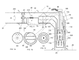
Fig.1 is a side view of a duct, in accordance with an exemplary embodiment of the present disclosure; -
Fig.1a is a cross-sectional view of a duct along A-A in accordance with an exemplary embodiment of the present disclosure; -
Fig.1b is a cross-sectional view of a duct along B-B in accordance with an exemplary embodiment of the present disclosure; -
Fig.1c is a cross-sectional view of a duct along C-C in accordance with an exemplary embodiment of the present disclosure; -
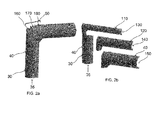
Fig.2a is an isometric view of a duct in accordance with an exemplary embodiment of the present disclosure; -
Fig.2b is an enlarged view of the of theFig 2a depicting parallel and concentric flows in the duct in accordance with an exemplary embodiment of the present disclosure; -
Fig.3a illustrates an arrangement of jet burners in which a duct is integrated in accordance with various exemplary embodiments of the present disclosure; -
Fig3b illustrates a top view of a tangential fired combustion system with the jet burners having integrated ducts; -
Fig 3c illustrates a side view of a combustion chamber of a boiler with the jet burner layers having integrated ducts; -
Fig.4a schematically shows a round burner in which duct is integrated in accordance with an exemplary embodiment of the present disclosure; -
Fig.4b shows a top view of a wall fired combustion system of a boiler with the round burners having integrated ducts; -
Fig.4c shows a side view of a wall fired combustion chamber equipped with the round burners with integrated ducts. - Referring now to
Figure 1 acombustion system 10 with acombustion area 20 in aboiler 25 includes afuel pipe 30 for deliveringfuel 35. Aduct 40 having abend 50 extended there through is in fluid communication with thefuel pipe 30 and thecombustion area 20 of theboiler 25. Theduct 40 is having anouter perimeter 45 and aninner perimeter 42. Theduct 40 includes afirst partition plate 60 to form a firstparallel flow 80 of the fuel between theouter perimeter 45 and thefirst partition plate 60, upstream of thebend 50. Thebend 50 provides a simple transition of the firstparallel flow 80 of the fuel into a firstconcentric flow 130 of the fuel. A firstconcentric conduit 110 is positioned in theduct 40 downstream of thebend 50 to deliver the firstconcentric flow 130 of the fuel for combustion. - Still referring to
FIG.1 , theduct 40 further includes asecond partition plate 70 placed next to thefirst partition plate 60 to form a secondparallel flow 90 of the fuel between thefirst partition plate 60 and thesecond partition plate 70 upstream of thebend 50. Thebend 50 provides a simple transition of the secondparallel flow 90 of the fuel into a secondconcentric flow 140 of the fuel. A secondconcentric conduit 120 is positioned in theduct 40 downstream of thebend 50 to deliver a secondconcentric flow 140 of the fuel for combustion. A thirdparallel flow 100 of the fuel is formed between theouter perimeter 45 and thesecond partition plate 70 upstream of thebend 50. Thebend 50 also provides a simple transition of thirdparallel flow 100 of the fuel into a thirdconcentric flow 150 of the fuel. Theduct 40 is positioned downstream of thebend 50 to deliver the thirdconcentric flow 150 of the fuel for combustion. Thefuel 35 comprises pulverized coal in form of dust, mixed and supplied along with primary air. It should be understood, however, that the disclosure is not limited in this regard and that different types of fuel, such as, but not limited to, other carbonaceous fuel may also be used. Velocity of the primary air which is a combination of pulverized fuel carrier air and dust of pulverized coal across theduct 40 is controlled. A ratio between load of the dust of the pulverized coal and the primary air is also controlled. - The
duct 40 is a fuel nozzle for the pulverized fuel, which also act as an ignition-injection nozzle. Apre ignition source 220 is positioned in theduct 40, preferably in the firstconcentric flow 130 of fuel downstream thebend 50. Thepre ignition source 220 is an electric igniter with anignition flame 225. It should be understood, however, that the disclosure is not limited in this regard and that different types of igniter, such as, but not limited to, a microwave system generating a plasma cloud/flame 225, electrodes with high voltages discharge generating plasma cloud/flame 225, electrodes connected to an electric circuit generating one or moreelectric arcs 225, electrodes connected to an electric circuit for generatingelectric sparks 225, and other systems creating ionizing and / or electrical fields or discharges may also be used. - In order to provide stage by stage ignition in an efficient and safe manner, the amount of the pulverised
fuel 35 in the firstconcentric flow 130 is controlled and adjusted to theignition flame 225 energy output volume. A first stage ignition takes place within the rear section of the firstconcentric flow 130. To control fuel flow concentration in the first 130, second 140 and third 150 concentric flow of fuel, theduct 40 is equipped withadjustable swirl vanes 200 and/or with other devices such as adjustableflat vanes 210 upstream thepartition walls fuel enrichment bypass 190 andfuel flow redistributors 240. The swirl vanes 200 and theflat vanes 210 can be fixed. Higher fuel concentrations in the firstconcentric flow 130 of the fuel enhance ignition process; therefore in order to increase fuel concentration in the firstconcentric flow 130 of the fuel, theduct 40 is equipped with thefuel enrichment bypass 190. Thebypass 190 transports a part of the fuel from the secondparallel flow 90 of the fuel and from the thirdparallel flow 100 of the fuel in theduct 40 to the firstconcentric conduit 110 to form the firstconcentric flow 130. The amount of the fuel transported viabypass 190 is controlled by theswirl vanes 200 and/or flat vanes 210.The stage by stage ignition is improved and controlled in rear sections of the first 130, second 140 and third 150 concentric flow of fuel by keeping thepre ignition source 220 in operation. If thepre ignition source 220 goes out of operation, the ignition of thefuel 35 moves from the rear sections of the first 130, second 140 and third 150 concentric flow of fuel to outside, into thecombustion area 20. During theboiler 25 start-up, after reaching approximately 30% of the total boiler capacity thepre ignition source 220 can be switched off, Therefore, theduct 40 serves as fuel ignition nozzle and as fuel injection nozzle when thepre ignition source 220 is switched off. Furthermore, use of theswirl vanes 200, theflat vanes 210, thefuel flow redistributors 240, thefuel enrichment bypass 190,duct temperature detectors 255, primary air velocity andtemperature monitoring system 250 allow influencing the ignition process by controlling the velocity of the pulverized fuel/air mixture, stoichiometry of the mixture, and temperature in theduct 40. After the ignited fuel leftduct outlet 55 and enter into the combustion area 20 a combustion flame is formed and stabilised with help ofsecondary air 260 provided by a fuel burner 230 which is ajet burner 231 or around burner 232. After theignitor 220 is switched off the combustion flame can stand alone. - As illustrated in
Figure 1a , a cross-sectional view of theduct 40 is shown along the line along A-A. InFigure 1b , a cross-sectional view of theduct 40 is shown along the line along B-B and inFigure 1c , a cross-sectional view of theduct 40 is shown along the line along C-C. - Referring now to
Figure 2a and Fig 2b , an isometric view of theduct 40 is shown where thebend 50 includes afirst portion 160 which is connected to thefirst partition plate 60. Thefirst partition plate 60 is connected with in turn with the firstconcentric conduit 110 to transition the firstparallel flow 80 of the fuel into the firstconcentric flow 130 of fuel. Asecond portion 170 is attached to thefirst portion 160 and in turn connect thesecond partition plate 70 with the secondconcentric conduit 120 to transition the secondparallel flow 90 into the secondconcentric flow 140 of fuel. The second concentric conduit120 surrounds the firstconcentric conduit 110 in such way that the firstconcentric flow 130 of fuel is surrounded by the secondconcentric flow 140 of fuel and remain separated as both the flow 130,140 flow in their respective conduits 110,120. Athird portion 180 is attached to thesecond portion 170 and in turn transition the thirdparallel flow 100 of the fuel into the thirdconcentric flow 150 of the fuel through theduct 40. Theduct 40 surround the secondconcentric conduit 120 in such way that the secondconcentric flow 140 of fuel is surrounded by the thirdconcentric flow 150 of fuel and remain separated as both the flow 140,150 flow in theirrespective conduits first portion 160,second portion 170 and thethird portion 180 has been attached and configured to form a stepping configuration. The ignition of the fuel occurs in rear sections of first 130, second 140 and third 150 concentric flow of fuel downstream thebend 50. - In reference to
Fig 3a an arrangement of thejet burners 231 includes theducts 40 in thefew jet burners 231 along withconventional nozzles 38 in other jet burners placed on acombustion chamber 22 of a tangentially fired combustion system. There is a combination oflower air supply 280 andintermediate air supply 290 adjusted around thejet burner 231 having theduct 40. Furthernext jet burner 231 having theduct 40 is placed between theintermediate air supply 290 andupper air supply 300 with offsetair supply 310. InFig 3b thejet burners 231 having integratedducts 40 have been placed in a tangential fired position. FurtherFig 3c illustrates a side view of thecombustion chamber 22 of the boiler with the jet burner layers 270 having integratedducts 40. In order to start-up the tangentially fired boiler without using any secondary fuel for example oil or gas a minimum fourconventional nozzles 38 is replaced withduct 40 making the oneburner layer 270 thereby, the firing capacity of theducts 40 is equal to or greater than 30% of boiler firing capacity. In case this condition is not be fulfilled with the oneburner layer 270, than two or more burner layers 270 have to be equipped withducts 40. - In
Fig.4a an arrangement of theround burner 232 includes theducts 40 in the fewround burners 232 along with normal nozzles in other round burners placed on acombustion chamber 22 of a wall fired combustion system. InFig 4b theround burners 232 having integratedducts 40 have been placed in a wall fired position. InFig 4c side views of thecombustion chamber 22 of the boiler with theround burner 232 having integratedducts 40. In order to start-up the wall fired boiler without using any secondary fuel for example oil or gas severalround burners 232 are equipped withducts 40. Theconventional nozzle 38 within theround burners 232 are replaced withducts 40, as shown inFig.4c , thereby, the firing capacity of theround burners 232 equipped withducts 40 is equal to or greater than 30% of boiler firing capacity. - The
system 10 is shown and described as havingconcentric conduits duct 40 also acting as concentric conduit. However; the present disclosure is not limited in this regard. For example, the disclosedsystem 10 may have aduct 40 with multiple numbers on concentric conduits depending upon the fuel amount and size of thesystem 10. Similarly the shape and configuration of the one or more concentric conduit may vary. - A method for providing combustion in the
boiler 25 having acombustion area 20 is provided. During the operation of thesystem 10, thefuel 35 in the form of dust of pulverized coal along with primary air is conveyed through thefuel pipe 30, through theduct 40, and into thecombustion area 20 of theboiler 25. A part of thefuel 35 in the form of the firstparallel flow 80 flowing between theouter perimeter 45 and thefirst partition plate 60 is in transition into the firstconcentric flow 130 of the fuel while passing through thebend 50. Thefirst partition plate 60 is connected to the firstconcentric conduit 110 through thefirst portion 160 in such a way that the firstparallel flow 80 after transition into the firstconcentric flow 130 flowing through the firstconcentric conduit 110 without mixing with the other concentric flows. Similarly another part of thefuel 35 in the form of the secondparallel flow 90 flowing between thefirst partition plate 60 and thesecond partition plate 70 is in transition into the secondconcentric flow 140 of the fuel while passing through thebend 50. Thesecond partition plate 70 is connected to the secondconcentric conduit 120 through thesecond portion 170 in such a way that the secondparallel flow 90 after transition into the secondconcentric flow 140 flowing through the secondconcentric conduit 120 without mixing with the other concentric flows. Remaining part of thefuel 35 in the form of the thirdparallel flow 100 flowing between thesecond partition plate 70 and theouter perimeter 45 is in transition into the thirdconcentric flow 150 of the fuel while passing through thebend 50. Theduct 40 is transformed due to thethird portion 180 in such a way that the thirdparallel flow 100 after transition into the thirdconcentric flow 150 flowing through theduct 40 without mixing with the other concentric flows. The bend is including thefirst portion 160,second portion 170 and thethird portion 180 and all theportions duct 40 is surrounding the secondconcentric conduit 120, which further surrounding the firstconcentric conduit 110. Further increasing thefuel 35 concentration in the firstconcentric flow 130 of the fuel, through thefuel enrichment bypass 190 by equipping theduct 40. Thebypass 190 allow transporting a part of the fuel from the secondparallel flow 90 of the fuel and from the thirdparallel flow 100 of the fuel in theduct 40 to the firstconcentric conduit 110 forming the first concentric flow130. The amount of the fuel transported viabypass 190 is controlled by theswirl vanes 200 and/orflat vanes 210. The stage by stage ignition is improved and controlled in rear sections of the first 130, second 140 and third 150 concentric flow of fuel by keeping thepre ignition source 220 in operation. - The foregoing descriptions of specific embodiments of the present disclosure have been presented for purposes of illustration and description. They are not intended to be exhaustive or to limit the present disclosure to the precise forms disclosed, and obviously many modifications and variations are possible in light of the above examples teaching. The embodiments were chosen and described in order to best explain the principles of the present disclosure and its practical application, to thereby enable others skilled in the art to best utilize the present disclosure and various embodiments with various modifications as are suited to the particular use contemplated. It is understood that various omission and substitutions of equivalents are contemplated as circumstance may suggest or render expedient, but such are intended to cover the application or implementation without departing from the scope of the claims of the present disclosure.
-
- 10
- System
- 20
- Combustion Area
- 22
- Combustion chamber
- 25
- Boiler
- 30
- Fuel Pipe
- 35
- Fuel
- 38
- Conventional Nozzle
- 40
- Duct
- 42
- Inner perimeter
- 45
- Outer Perimeter
- 50
- Bend
- 55
- Duct Outlet
- 60
- First Partition Plate
- 70
- Second Partition Plate
- 80
- First Parallel Flow
- 90
- Second Parallel Flow
- 100
- Third Parallel Flow
- 110
- First Concentric Conduit
- 120
- Second Concentric Conduit
- 130
- First Concentric flow of fuel
- 140
- Second Concentric flow of fuel
- 150
- Third Concentric flow of fuel
- 160
- First Portion
- 170
- Second Portion
- 180
- Third Portion
- 190
- Bypass
- 200
- Swirl Vanes
- 210
- Flat Vanes
- 220
- Ignitor
- 225
- Flame
- 230
- Fuel Burner
- 231
- Jet Burner
- 232
- Round Burner
- 240
- Fuel Redistributor
- 250
- Primary Air Velocity and Duct Temperature Detector
- 255
- Duct Temperature Detector
- 260
- Secondary Air
- 270
- Jet Burner Layer
- 280
- Lower Air
- 290
- Intermediate Air
- 300
- Upper Air
- 310
- Off Section Air
Claims (20)
- A system (10) for providing combustion in a boiler (25) having a combustion area (20) comprising:a fuel pipe (30) operable to deliver fuel (35);a duct (40) with an outer perimeter (45) having a bend (50) extended there through, the duct (40) being in fluid communication with the fuel pipe (30) and the combustion area (20) of the boiler(25);characterized in that the duct (40) comprisinga first partition plate (60) disposed in the duct (40) to form a first parallel flow (80) of the fuel between the outer perimeter (45) and the first partition plate (60), upstream of the bend (50), anda first concentric conduit (110), positioned in the duct (40) downstream of the bend (50), to deliver a first concentric flow (130) of the fuel for combustion, wherein,the bend (50) between the first partition plate (60) and the first concentric conduit (110) is configured to transition the first parallel flow (80) of the fuel into the first concentric flow (130) of the fuel.
- The system (10) according to claim 1, wherein the duct (40) further comprising:a second partition plate (70), disposed in the duct (40), to form a second parallel flow (90) of the fuel between the first partition plate (60) and the second partition plate (70) upstream of the bend (50), anda second concentric conduit (120), positioned in the duct (40) downstream of the bend (50), to deliver a second concentric flow (140) of the fuel for combustion, wherein,the bend (50) between the second partition plate (70) and the second concentric conduit (120) is configured to transition the second parallel flow (90) of the fuel into the second concentric flow (140) of the fuel.
- The system (10) according to claim 2, wherein the second partition plate (70) forms a third parallel flow (100) of the fuel between the outer perimeter (45) and the second partition plate (70), upstream of the bend (50), and
the duct (40) is positioned downstream the bend (50) to deliver a third concentric flow (150) of the fuel for combustion, wherein,
the bend (50) is configured in the duct (40) to transition the third parallel flow (100) of the fuel into the third concentric flow (150) of the fuel. - The system (10) according to claim 1, wherein the bend (50) comprising:a first portion (160) configured to connect the first partition plate (60) with the first concentric conduit (110) to transition the first parallel flow (80) of the fuel into the first concentric flow of fuel (130);a second portion (170) attached to the first portion (160) and configured to connect the second partition plate (70) with the second concentric conduit (120) to transition the second parallel flow (90) into the second concentric flow of fuel (140), wherein the second concentric conduit (120) surrounds the first concentric conduit (110);a third portion (180) attached to the second portion (170) and configured to transition the third parallel flow (100) of the fuel into the third concentric flow (150) of the fuel through the duct (40), wherein the duct (40) surrounds the second concentric conduit (120); andwherein the first portion (160), second portion (170) and the third portion (180) configured to form a stepping configuration.
- The system (10) according to claim 1, wherein a bypass (190) is provided in the duct (40) upstream the bend (50) to transport a part of second parallel flow(90) of the fuel and third parallel flow(100) of the fuel in the duct (40) to the first concentric conduit(110) through the first portion(160).
- The system (10) according to claim 5, wherein at least one swirl vane (200) and at least one flat vanes (210) is provided upstream the partition plates (60,70) to control amount of the fuel transported through the bypass (190) and/or first (80), second (90), and third(100) parallel flow.
- The system (10) according to claim 1, wherein a pre ignition source (220) is positioned in the duct (40), preferably in the first concentric flow (130) of fuel downstream the bend (50).
- The system (10) according to claim 1, wherein, the duct (40) is an ignition-injection nozzle.
- The system (10) according to claim 8, wherein ignition of the fuel occurs in rear sections of first (130), second (140) and third (150) concentric flow of fuel downstream the bend (50).
- A system (10) for providing combustion in a boiler (25) having a combustion area (20) comprising:a fuel burner (230) is fitted with the ignition-injection nozzle as claimed in claim 8.
- A method for providing combustion in a boiler (25) having a combustion area (20) comprising:providing a fuel pipe (30) operable to deliver fuel;providing a duct (40) with an outer perimeter (45) having a bend (50) extended there through, the duct (40) is in fluid communication with the fuel pipe (30) and the combustion area (20) of the boiler (25);disposing a first partition plate (60) in the duct (40) to enable forming a first parallel flow (80) of the fuel between the outer perimeter (45) and the first partition plate (60), upstream of the bend (50);positioning a first concentric conduit (110) in the duct (40) downstream of the bend (50) to enable delivery of a first concentric flow (130) of the fuel for combustion, wherein,configuring the bend (50) between the first partition plate (60) and the first concentric conduit (110) to enable transition of the first parallel flow (80) of the fuel into the first concentric flow (130) of the fuel.
- The method according to claim 11, further comprising the steps of:disposing a second partition plate (70) in the duct (40) to enable forming a second parallel flow (90) of the fuel between the first partition plate (60) and the second partition plate (70) upstream of the bend (50);positioning a second concentric conduit (120) in the duct (40) downstream of the bend (50) to enable delivery of a second concentric flow (140) of the fuel for combustion, wherein,configuring the bend (50) between the second partition plate (70) and the second concentric conduit (120) to enable transition of the second parallel flow (90) of the fuel into the second concentric flow (140) of the fuel.
- The method according to claim 12, wherein the second partition plate (70) further:forming a third parallel flow (100) of the fuel between the outer perimeter (45) and the second partition plate (70), upstream of the bend (50);positioning the duct downstream the bend (50) to enable delivery of a third concentric flow (150) of the fuel for combustion, wherein,configuring the bend (50) in the duct (40) to enable transition of the third parallel flow (100) of the fuel into the third concentric flow (150) of the fuel.
- The method according to claim 11, wherein configuring the bend (50) comprising:connecting the first partition plate (60) with the first concentric conduit (110) by a first portion (160) to enable transition of the first parallel flow (80) of the fuel into the first concentric flow of fuel (130);attaching a second portion (170) to the first portion (160) to connect the second partition plate (70) with the second concentric conduit (120) to enable transition of the second parallel flow (90) into the second concentric flow of fuel (140), wherein the second concentric conduit (120) surrounds the first concentric conduit (110);attaching a third portion (180) to the second portion (170) to enable transition the third parallel flow (100) of the fuel into the third concentric flow (150) of the fuel through the duct (40), wherein the duct (40) surrounds the second concentric conduit (120); andwherein the first portion (160), second portion (170) and the third portion (180) configured to form a stepping configuration.
- The method according to claim 11, wherein,
providing a bypass (190) in the duct (40) upstream the bend (50) to transport a part of second parallel flow (90) of the fuel and third parallel flow (100) of the fuel in the duct (40) to the first concentric conduit(110) through first portion (160). - The method according to claim 11, wherein,
providing at least one swirl vane (200) and at least one flat vanes (210) upstream the partition plates (60,70) to control amount of the fuel (35) transported through the bypass (190). - The method according to claim 11, wherein positioning a pre ignition source (220) in the duct (40), preferably in the first concentric flow (130) of fuel downstream the bend (50).
- The method according to claim 11, wherein the duct (40) is an ignition-injection nozzle.
- The method according to claim 11, wherein,
igniting the fuel in rear sections of first (130), second (140) and third (150) concentric flow of fuel downstream the bend (50). - A method for providing combustion in a boiler (25) having a combustion area (20) comprising:using nozzle of claim 18 in a fuel burner 230.
Priority Applications (4)
| Application Number | Priority Date | Filing Date | Title |
|---|---|---|---|
| PL15180895T PL3130851T3 (en) | 2015-08-13 | 2015-08-13 | System and method for providing combustion in a boiler |
| EP15180895.3A EP3130851B1 (en) | 2015-08-13 | 2015-08-13 | System and method for providing combustion in a boiler |
| US15/228,001 US10955131B2 (en) | 2015-08-13 | 2016-08-04 | System and method for providing combustion in a boiler |
| CN201610659838.0A CN106568079B (en) | 2015-08-13 | 2016-08-12 | System and method for providing combustion in a boiler |
Applications Claiming Priority (1)
| Application Number | Priority Date | Filing Date | Title |
|---|---|---|---|
| EP15180895.3A EP3130851B1 (en) | 2015-08-13 | 2015-08-13 | System and method for providing combustion in a boiler |
Publications (2)
| Publication Number | Publication Date |
|---|---|
| EP3130851A1 true EP3130851A1 (en) | 2017-02-15 |
| EP3130851B1 EP3130851B1 (en) | 2021-03-24 |
Family
ID=53969158
Family Applications (1)
| Application Number | Title | Priority Date | Filing Date |
|---|---|---|---|
| EP15180895.3A Active EP3130851B1 (en) | 2015-08-13 | 2015-08-13 | System and method for providing combustion in a boiler |
Country Status (4)
| Country | Link |
|---|---|
| US (1) | US10955131B2 (en) |
| EP (1) | EP3130851B1 (en) |
| CN (1) | CN106568079B (en) |
| PL (1) | PL3130851T3 (en) |
Families Citing this family (3)
| Publication number | Priority date | Publication date | Assignee | Title |
|---|---|---|---|---|
| RS60283B1 (en) * | 2014-11-28 | 2020-06-30 | General Electric Technology Gmbh | A combustion system for a boiler |
| JP2017223423A (en) * | 2016-06-17 | 2017-12-21 | 株式会社Ihi | Pulverized coal burner |
| CN110360548B (en) * | 2019-08-01 | 2020-07-14 | 沈阳航空航天大学 | Low NOx combustor based on plasma excitation staged combustion enhancement |
Citations (7)
| Publication number | Priority date | Publication date | Assignee | Title |
|---|---|---|---|---|
| US5769008A (en) * | 1994-12-29 | 1998-06-23 | Maloe Gosudarstvennoe Vnedrencheskoe Predpriyatie "Politekhenergo" | Low-emission swirling-type furnace |
| US6116171A (en) * | 1994-11-14 | 2000-09-12 | Mitsubishi Jukogyo Kabushiki Kaisha | Pulverized coal combustion burner |
| JP2002340306A (en) * | 2001-05-17 | 2002-11-27 | Babcock Hitachi Kk | Burner for burning solid fuel and combustion device equipped therewith |
| EP2019263A1 (en) * | 2006-05-17 | 2009-01-28 | Hangzhou Yineng Energy Retrenchment Technology Co. | A pulverized coal burner with a baffle |
| EP2172706A1 (en) | 2007-07-19 | 2010-04-07 | Yantai Longyuan Power Technology Co., Ltd. | A burner ignited by plasma |
| CN101832551A (en) * | 2010-06-18 | 2010-09-15 | 上海交通大学 | Adjustable center weak swirl pulverized coal burner |
| EP2253884A1 (en) | 2008-03-14 | 2010-11-24 | Yantai Longyuan Power Technology Co. Ltd. | A method of reducing nitrogen oxides of a pulverized coal boiler using inner combustion type burners |
Family Cites Families (22)
| Publication number | Priority date | Publication date | Assignee | Title |
|---|---|---|---|---|
| US2216508A (en) * | 1938-10-26 | 1940-10-01 | John S Zink | Combination gas and oil burner |
| US3729285A (en) * | 1972-05-22 | 1973-04-24 | G Schwedersky | Burner and method of operating it to control the production of nitrogen oxides |
| FR2499681A1 (en) * | 1981-02-06 | 1982-08-13 | Stein Industrie | DIRECT IGNITION DEVICE FOR POOR PULVERIZED SOLID FUELS IN COLD COMBUSTION CHAMBERS |
| FR2569256B1 (en) * | 1984-08-16 | 1989-04-07 | Stein Industrie | IGNITION AND COMBUSTION SUPPORT BURNER FOR FULLY SOLID SPRAYED FUEL, AND COMBUSTION CHAMBER COMPRISING SUCH BURNERS |
| US4902221A (en) * | 1987-05-12 | 1990-02-20 | Control Systems Company | Burner assembly for coal fired furnaces |
| FI85910C (en) | 1989-01-16 | 1992-06-10 | Imatran Voima Oy | FOERFARANDE OCH ANORDNING FOER ATT STARTA PANNAN I ETT KRAFTVERK SOM UTNYTTJAR FAST BRAENSLE SAMT FOER ATT SAEKERSTAELLA FOERBRAENNINGEN AV BRAENSLET. |
| US7717701B2 (en) * | 2006-10-24 | 2010-05-18 | Air Products And Chemicals, Inc. | Pulverized solid fuel burner |
| CN100462624C (en) | 2006-12-01 | 2009-02-18 | 侯桂林 | Ignition device for once-through burner of pulverized coal boiler |
| CN201081231Y (en) | 2006-12-30 | 2008-07-02 | 杭州意能节能技术有限公司 | A thick-thin fuel-saving ignition pulverized coal burner |
| CN101349435B (en) * | 2007-07-19 | 2012-06-27 | 烟台龙源电力技术股份有限公司 | Plasma ignition combustor |
| JP4969464B2 (en) * | 2008-01-08 | 2012-07-04 | 三菱重工業株式会社 | Burner structure |
| EP2273193B1 (en) * | 2008-04-10 | 2016-03-16 | Mitsubishi Hitachi Power Systems, Ltd. | Solid fuel burner, combustion apparatus using solid fuel burner |
| US9151434B2 (en) * | 2008-12-18 | 2015-10-06 | Alstom Technology Ltd | Coal rope distributor with replaceable wear components |
| US9857077B2 (en) * | 2008-12-18 | 2018-01-02 | General Electric Technology Gmbh | Coal rope distributor with replaceable wear components |
| US20100275824A1 (en) * | 2009-04-29 | 2010-11-04 | Larue Albert D | Biomass center air jet burner |
| US9593795B2 (en) * | 2009-11-02 | 2017-03-14 | General Electric Technology Gmbh | Fuel head assembly with replaceable wear components |
| WO2012088110A1 (en) | 2010-12-23 | 2012-06-28 | Alstom Technology Ltd | System and method for reducing emissions from a boiler |
| CN102305415B (en) | 2011-10-18 | 2013-10-09 | 上海锅炉厂有限公司 | Plasma oil-free ignition system in oxygen-enriched environments |
| WO2013097165A1 (en) | 2011-12-30 | 2013-07-04 | American Air Liquide, Inc. | Process for producing flat flame by oxy-solid fuel burner |
| JP5897364B2 (en) * | 2012-03-21 | 2016-03-30 | 川崎重工業株式会社 | Pulverized coal biomass mixed burner |
| JP5897363B2 (en) * | 2012-03-21 | 2016-03-30 | 川崎重工業株式会社 | Pulverized coal biomass mixed burner |
| PL2908051T3 (en) * | 2014-02-12 | 2021-05-31 | General Electric Technology Gmbh | Igniter lance and method for operating a burner having said igniter lance |
-
2015
- 2015-08-13 EP EP15180895.3A patent/EP3130851B1/en active Active
- 2015-08-13 PL PL15180895T patent/PL3130851T3/en unknown
-
2016
- 2016-08-04 US US15/228,001 patent/US10955131B2/en active Active
- 2016-08-12 CN CN201610659838.0A patent/CN106568079B/en not_active Expired - Fee Related
Patent Citations (7)
| Publication number | Priority date | Publication date | Assignee | Title |
|---|---|---|---|---|
| US6116171A (en) * | 1994-11-14 | 2000-09-12 | Mitsubishi Jukogyo Kabushiki Kaisha | Pulverized coal combustion burner |
| US5769008A (en) * | 1994-12-29 | 1998-06-23 | Maloe Gosudarstvennoe Vnedrencheskoe Predpriyatie "Politekhenergo" | Low-emission swirling-type furnace |
| JP2002340306A (en) * | 2001-05-17 | 2002-11-27 | Babcock Hitachi Kk | Burner for burning solid fuel and combustion device equipped therewith |
| EP2019263A1 (en) * | 2006-05-17 | 2009-01-28 | Hangzhou Yineng Energy Retrenchment Technology Co. | A pulverized coal burner with a baffle |
| EP2172706A1 (en) | 2007-07-19 | 2010-04-07 | Yantai Longyuan Power Technology Co., Ltd. | A burner ignited by plasma |
| EP2253884A1 (en) | 2008-03-14 | 2010-11-24 | Yantai Longyuan Power Technology Co. Ltd. | A method of reducing nitrogen oxides of a pulverized coal boiler using inner combustion type burners |
| CN101832551A (en) * | 2010-06-18 | 2010-09-15 | 上海交通大学 | Adjustable center weak swirl pulverized coal burner |
Also Published As
| Publication number | Publication date |
|---|---|
| PL3130851T3 (en) | 2021-08-02 |
| EP3130851B1 (en) | 2021-03-24 |
| US20170045218A1 (en) | 2017-02-16 |
| CN106568079A (en) | 2017-04-19 |
| CN106568079B (en) | 2020-10-23 |
| US10955131B2 (en) | 2021-03-23 |
Similar Documents
| Publication | Publication Date | Title |
|---|---|---|
| CA2510713C (en) | Staged combustion system with ignition-assisted fuel lances | |
| US11226094B2 (en) | Burners and methods for use thereof | |
| EP2908051B1 (en) | Igniter lance and method for operating a burner having said igniter lance | |
| EP2795190B1 (en) | Burner for burning a pulverulent fuel for a boiler having a plasma ignition torch | |
| TWI540203B (en) | Central burner for multi-fuel multiple lance burner system | |
| US20130255551A1 (en) | Biomass Combustion | |
| JPS6159109A (en) | Burner for maintaining ignition and combustion for crushed solid fossil fuel and combustion chamber with such burner | |
| US10955131B2 (en) | System and method for providing combustion in a boiler | |
| EP2751484B1 (en) | Combustion apparatus with indirect firing system | |
| EP2655965B1 (en) | Method for reducing emissions from a boiler | |
| CN103946634A (en) | Oil burners, solid fuel incineration burner units and solid fuel incineration boilers | |
| CN116608465A (en) | Ammonia burner with space grading ammonia injection function | |
| WO2024082443A1 (en) | Ammonia and coal mixed combustion system | |
| CN110462291B (en) | System, method and apparatus for solid fuel ignition | |
| RU2731081C1 (en) | Method for flare combustion of a fuel-air mixture and device for realizing a method using an electro-ionization igniter | |
| RU2244878C2 (en) | Igniter (versions) | |
| EP0152389A2 (en) | Burner for burning pulverulent fuel | |
| CN110160040B (en) | Combustion apparatus | |
| US11555612B2 (en) | Dual fuel direct ignition burners | |
| EP4253838A1 (en) | Gas burner with low nox emission | |
| RU20368U1 (en) | GAS INJECTION BURNER | |
| RU2298133C2 (en) | Multiflame injector torch | |
| IL266905B1 (en) | Dual fuel direct ignition burners | |
| WO2016179909A1 (en) | Burner design for pulverized coal-fired boilers using minimal ignition fuel | |
| HK1154931A (en) | Combustion method and apparatus |
Legal Events
| Date | Code | Title | Description |
|---|---|---|---|
| PUAI | Public reference made under article 153(3) epc to a published international application that has entered the european phase |
Free format text: ORIGINAL CODE: 0009012 |
|
| STAA | Information on the status of an ep patent application or granted ep patent |
Free format text: STATUS: THE APPLICATION HAS BEEN PUBLISHED |
|
| AK | Designated contracting states |
Kind code of ref document: A1 Designated state(s): AL AT BE BG CH CY CZ DE DK EE ES FI FR GB GR HR HU IE IS IT LI LT LU LV MC MK MT NL NO PL PT RO RS SE SI SK SM TR |
|
| AX | Request for extension of the european patent |
Extension state: BA ME |
|
| STAA | Information on the status of an ep patent application or granted ep patent |
Free format text: STATUS: REQUEST FOR EXAMINATION WAS MADE |
|
| 17P | Request for examination filed |
Effective date: 20170816 |
|
| RBV | Designated contracting states (corrected) |
Designated state(s): AL AT BE BG CH CY CZ DE DK EE ES FI FR GB GR HR HU IE IS IT LI LT LU LV MC MK MT NL NO PL PT RO RS SE SI SK SM TR |
|
| STAA | Information on the status of an ep patent application or granted ep patent |
Free format text: STATUS: EXAMINATION IS IN PROGRESS |
|
| 17Q | First examination report despatched |
Effective date: 20200120 |
|
| GRAP | Despatch of communication of intention to grant a patent |
Free format text: ORIGINAL CODE: EPIDOSNIGR1 |
|
| STAA | Information on the status of an ep patent application or granted ep patent |
Free format text: STATUS: GRANT OF PATENT IS INTENDED |
|
| INTG | Intention to grant announced |
Effective date: 20201023 |
|
| GRAS | Grant fee paid |
Free format text: ORIGINAL CODE: EPIDOSNIGR3 |
|
| GRAA | (expected) grant |
Free format text: ORIGINAL CODE: 0009210 |
|
| STAA | Information on the status of an ep patent application or granted ep patent |
Free format text: STATUS: THE PATENT HAS BEEN GRANTED |
|
| AK | Designated contracting states |
Kind code of ref document: B1 Designated state(s): AL AT BE BG CH CY CZ DE DK EE ES FI FR GB GR HR HU IE IS IT LI LT LU LV MC MK MT NL NO PL PT RO RS SE SI SK SM TR |
|
| REG | Reference to a national code |
Ref country code: GB Ref legal event code: FG4D |
|
| REG | Reference to a national code |
Ref country code: CH Ref legal event code: EP |
|
| REG | Reference to a national code |
Ref country code: IE Ref legal event code: FG4D |
|
| REG | Reference to a national code |
Ref country code: AT Ref legal event code: REF Ref document number: 1374846 Country of ref document: AT Kind code of ref document: T Effective date: 20210415 Ref country code: DE Ref legal event code: R096 Ref document number: 602015067157 Country of ref document: DE |
|
| RAP4 | Party data changed (patent owner data changed or rights of a patent transferred) |
Owner name: GENERAL ELECTRIC TECHNOLOGY GMBH |
|
| REG | Reference to a national code |
Ref country code: LT Ref legal event code: MG9D |
|
| PG25 | Lapsed in a contracting state [announced via postgrant information from national office to epo] |
Ref country code: FI Free format text: LAPSE BECAUSE OF FAILURE TO SUBMIT A TRANSLATION OF THE DESCRIPTION OR TO PAY THE FEE WITHIN THE PRESCRIBED TIME-LIMIT Effective date: 20210324 Ref country code: GR Free format text: LAPSE BECAUSE OF FAILURE TO SUBMIT A TRANSLATION OF THE DESCRIPTION OR TO PAY THE FEE WITHIN THE PRESCRIBED TIME-LIMIT Effective date: 20210625 Ref country code: HR Free format text: LAPSE BECAUSE OF FAILURE TO SUBMIT A TRANSLATION OF THE DESCRIPTION OR TO PAY THE FEE WITHIN THE PRESCRIBED TIME-LIMIT Effective date: 20210324 Ref country code: NO Free format text: LAPSE BECAUSE OF FAILURE TO SUBMIT A TRANSLATION OF THE DESCRIPTION OR TO PAY THE FEE WITHIN THE PRESCRIBED TIME-LIMIT Effective date: 20210624 Ref country code: BG Free format text: LAPSE BECAUSE OF FAILURE TO SUBMIT A TRANSLATION OF THE DESCRIPTION OR TO PAY THE FEE WITHIN THE PRESCRIBED TIME-LIMIT Effective date: 20210624 |
|
| PG25 | Lapsed in a contracting state [announced via postgrant information from national office to epo] |
Ref country code: RS Free format text: LAPSE BECAUSE OF FAILURE TO SUBMIT A TRANSLATION OF THE DESCRIPTION OR TO PAY THE FEE WITHIN THE PRESCRIBED TIME-LIMIT Effective date: 20210324 Ref country code: LV Free format text: LAPSE BECAUSE OF FAILURE TO SUBMIT A TRANSLATION OF THE DESCRIPTION OR TO PAY THE FEE WITHIN THE PRESCRIBED TIME-LIMIT Effective date: 20210324 Ref country code: SE Free format text: LAPSE BECAUSE OF FAILURE TO SUBMIT A TRANSLATION OF THE DESCRIPTION OR TO PAY THE FEE WITHIN THE PRESCRIBED TIME-LIMIT Effective date: 20210324 |
|
| REG | Reference to a national code |
Ref country code: NL Ref legal event code: MP Effective date: 20210324 |
|
| REG | Reference to a national code |
Ref country code: AT Ref legal event code: MK05 Ref document number: 1374846 Country of ref document: AT Kind code of ref document: T Effective date: 20210324 |
|
| PG25 | Lapsed in a contracting state [announced via postgrant information from national office to epo] |
Ref country code: NL Free format text: LAPSE BECAUSE OF FAILURE TO SUBMIT A TRANSLATION OF THE DESCRIPTION OR TO PAY THE FEE WITHIN THE PRESCRIBED TIME-LIMIT Effective date: 20210324 |
|
| PG25 | Lapsed in a contracting state [announced via postgrant information from national office to epo] |
Ref country code: SM Free format text: LAPSE BECAUSE OF FAILURE TO SUBMIT A TRANSLATION OF THE DESCRIPTION OR TO PAY THE FEE WITHIN THE PRESCRIBED TIME-LIMIT Effective date: 20210324 Ref country code: EE Free format text: LAPSE BECAUSE OF FAILURE TO SUBMIT A TRANSLATION OF THE DESCRIPTION OR TO PAY THE FEE WITHIN THE PRESCRIBED TIME-LIMIT Effective date: 20210324 Ref country code: LT Free format text: LAPSE BECAUSE OF FAILURE TO SUBMIT A TRANSLATION OF THE DESCRIPTION OR TO PAY THE FEE WITHIN THE PRESCRIBED TIME-LIMIT Effective date: 20210324 Ref country code: AT Free format text: LAPSE BECAUSE OF FAILURE TO SUBMIT A TRANSLATION OF THE DESCRIPTION OR TO PAY THE FEE WITHIN THE PRESCRIBED TIME-LIMIT Effective date: 20210324 |
|
| PG25 | Lapsed in a contracting state [announced via postgrant information from national office to epo] |
Ref country code: PT Free format text: LAPSE BECAUSE OF FAILURE TO SUBMIT A TRANSLATION OF THE DESCRIPTION OR TO PAY THE FEE WITHIN THE PRESCRIBED TIME-LIMIT Effective date: 20210726 Ref country code: ES Free format text: LAPSE BECAUSE OF FAILURE TO SUBMIT A TRANSLATION OF THE DESCRIPTION OR TO PAY THE FEE WITHIN THE PRESCRIBED TIME-LIMIT Effective date: 20210324 Ref country code: SK Free format text: LAPSE BECAUSE OF FAILURE TO SUBMIT A TRANSLATION OF THE DESCRIPTION OR TO PAY THE FEE WITHIN THE PRESCRIBED TIME-LIMIT Effective date: 20210324 Ref country code: RO Free format text: LAPSE BECAUSE OF FAILURE TO SUBMIT A TRANSLATION OF THE DESCRIPTION OR TO PAY THE FEE WITHIN THE PRESCRIBED TIME-LIMIT Effective date: 20210324 Ref country code: IS Free format text: LAPSE BECAUSE OF FAILURE TO SUBMIT A TRANSLATION OF THE DESCRIPTION OR TO PAY THE FEE WITHIN THE PRESCRIBED TIME-LIMIT Effective date: 20210724 |
|
| REG | Reference to a national code |
Ref country code: DE Ref legal event code: R097 Ref document number: 602015067157 Country of ref document: DE |
|
| PG25 | Lapsed in a contracting state [announced via postgrant information from national office to epo] |
Ref country code: DK Free format text: LAPSE BECAUSE OF FAILURE TO SUBMIT A TRANSLATION OF THE DESCRIPTION OR TO PAY THE FEE WITHIN THE PRESCRIBED TIME-LIMIT Effective date: 20210324 Ref country code: AL Free format text: LAPSE BECAUSE OF FAILURE TO SUBMIT A TRANSLATION OF THE DESCRIPTION OR TO PAY THE FEE WITHIN THE PRESCRIBED TIME-LIMIT Effective date: 20210324 |
|
| PLBE | No opposition filed within time limit |
Free format text: ORIGINAL CODE: 0009261 |
|
| STAA | Information on the status of an ep patent application or granted ep patent |
Free format text: STATUS: NO OPPOSITION FILED WITHIN TIME LIMIT |
|
| PG25 | Lapsed in a contracting state [announced via postgrant information from national office to epo] |
Ref country code: SI Free format text: LAPSE BECAUSE OF FAILURE TO SUBMIT A TRANSLATION OF THE DESCRIPTION OR TO PAY THE FEE WITHIN THE PRESCRIBED TIME-LIMIT Effective date: 20210324 |
|
| 26N | No opposition filed |
Effective date: 20220104 |
|
| REG | Reference to a national code |
Ref country code: CH Ref legal event code: PL |
|
| PG25 | Lapsed in a contracting state [announced via postgrant information from national office to epo] |
Ref country code: MC Free format text: LAPSE BECAUSE OF FAILURE TO SUBMIT A TRANSLATION OF THE DESCRIPTION OR TO PAY THE FEE WITHIN THE PRESCRIBED TIME-LIMIT Effective date: 20210324 |
|
| REG | Reference to a national code |
Ref country code: BE Ref legal event code: MM Effective date: 20210831 |
|
| GBPC | Gb: european patent ceased through non-payment of renewal fee |
Effective date: 20210813 |
|
| PG25 | Lapsed in a contracting state [announced via postgrant information from national office to epo] |
Ref country code: LI Free format text: LAPSE BECAUSE OF NON-PAYMENT OF DUE FEES Effective date: 20210831 Ref country code: CH Free format text: LAPSE BECAUSE OF NON-PAYMENT OF DUE FEES Effective date: 20210831 |
|
| PG25 | Lapsed in a contracting state [announced via postgrant information from national office to epo] |
Ref country code: IS Free format text: LAPSE BECAUSE OF FAILURE TO SUBMIT A TRANSLATION OF THE DESCRIPTION OR TO PAY THE FEE WITHIN THE PRESCRIBED TIME-LIMIT Effective date: 20210724 Ref country code: LU Free format text: LAPSE BECAUSE OF NON-PAYMENT OF DUE FEES Effective date: 20210813 |
|
| PG25 | Lapsed in a contracting state [announced via postgrant information from national office to epo] |
Ref country code: IE Free format text: LAPSE BECAUSE OF NON-PAYMENT OF DUE FEES Effective date: 20210813 Ref country code: GB Free format text: LAPSE BECAUSE OF NON-PAYMENT OF DUE FEES Effective date: 20210813 Ref country code: FR Free format text: LAPSE BECAUSE OF NON-PAYMENT OF DUE FEES Effective date: 20210831 Ref country code: BE Free format text: LAPSE BECAUSE OF NON-PAYMENT OF DUE FEES Effective date: 20210831 |
|
| PG25 | Lapsed in a contracting state [announced via postgrant information from national office to epo] |
Ref country code: IT Free format text: LAPSE BECAUSE OF FAILURE TO SUBMIT A TRANSLATION OF THE DESCRIPTION OR TO PAY THE FEE WITHIN THE PRESCRIBED TIME-LIMIT Effective date: 20210324 |
|
| PG25 | Lapsed in a contracting state [announced via postgrant information from national office to epo] |
Ref country code: HU Free format text: LAPSE BECAUSE OF FAILURE TO SUBMIT A TRANSLATION OF THE DESCRIPTION OR TO PAY THE FEE WITHIN THE PRESCRIBED TIME-LIMIT; INVALID AB INITIO Effective date: 20150813 |
|
| P01 | Opt-out of the competence of the unified patent court (upc) registered |
Effective date: 20230523 |
|
| PG25 | Lapsed in a contracting state [announced via postgrant information from national office to epo] |
Ref country code: CY Free format text: LAPSE BECAUSE OF FAILURE TO SUBMIT A TRANSLATION OF THE DESCRIPTION OR TO PAY THE FEE WITHIN THE PRESCRIBED TIME-LIMIT Effective date: 20210324 |
|
| PGFP | Annual fee paid to national office [announced via postgrant information from national office to epo] |
Ref country code: CZ Payment date: 20230725 Year of fee payment: 9 |
|
| PGFP | Annual fee paid to national office [announced via postgrant information from national office to epo] |
Ref country code: PL Payment date: 20230721 Year of fee payment: 9 Ref country code: DE Payment date: 20230720 Year of fee payment: 9 |
|
| PG25 | Lapsed in a contracting state [announced via postgrant information from national office to epo] |
Ref country code: MK Free format text: LAPSE BECAUSE OF FAILURE TO SUBMIT A TRANSLATION OF THE DESCRIPTION OR TO PAY THE FEE WITHIN THE PRESCRIBED TIME-LIMIT Effective date: 20210324 |
|
| PG25 | Lapsed in a contracting state [announced via postgrant information from national office to epo] |
Ref country code: MT Free format text: LAPSE BECAUSE OF FAILURE TO SUBMIT A TRANSLATION OF THE DESCRIPTION OR TO PAY THE FEE WITHIN THE PRESCRIBED TIME-LIMIT Effective date: 20210324 |
|
| REG | Reference to a national code |
Ref country code: DE Ref legal event code: R119 Ref document number: 602015067157 Country of ref document: DE |
|
| PG25 | Lapsed in a contracting state [announced via postgrant information from national office to epo] |
Ref country code: CZ Free format text: LAPSE BECAUSE OF NON-PAYMENT OF DUE FEES Effective date: 20240813 |
|
| PG25 | Lapsed in a contracting state [announced via postgrant information from national office to epo] |
Ref country code: DE Free format text: LAPSE BECAUSE OF NON-PAYMENT OF DUE FEES Effective date: 20250301 |
|
| PGFP | Annual fee paid to national office [announced via postgrant information from national office to epo] |
Ref country code: TR Payment date: 20250728 Year of fee payment: 11 |
|
| PG25 | Lapsed in a contracting state [announced via postgrant information from national office to epo] |
Ref country code: PL Free format text: LAPSE BECAUSE OF NON-PAYMENT OF DUE FEES Effective date: 20240813 |