EP3130800A1 - Windenergieanlagenrotorblatt mit einer funkenstrecke - Google Patents
Windenergieanlagenrotorblatt mit einer funkenstrecke Download PDFInfo
- Publication number
- EP3130800A1 EP3130800A1 EP15180399.6A EP15180399A EP3130800A1 EP 3130800 A1 EP3130800 A1 EP 3130800A1 EP 15180399 A EP15180399 A EP 15180399A EP 3130800 A1 EP3130800 A1 EP 3130800A1
- Authority
- EP
- European Patent Office
- Prior art keywords
- wind turbine
- rotor blade
- turbine rotor
- electrode
- lightning protection
- Prior art date
- Legal status (The legal status is an assumption and is not a legal conclusion. Google has not performed a legal analysis and makes no representation as to the accuracy of the status listed.)
- Granted
Links
Images



Classifications
-
- F—MECHANICAL ENGINEERING; LIGHTING; HEATING; WEAPONS; BLASTING
- F03—MACHINES OR ENGINES FOR LIQUIDS; WIND, SPRING, OR WEIGHT MOTORS; PRODUCING MECHANICAL POWER OR A REACTIVE PROPULSIVE THRUST, NOT OTHERWISE PROVIDED FOR
- F03D—WIND MOTORS
- F03D80/00—Details, components or accessories not provided for in groups F03D1/00 - F03D17/00
- F03D80/30—Lightning protection
-
- F—MECHANICAL ENGINEERING; LIGHTING; HEATING; WEAPONS; BLASTING
- F03—MACHINES OR ENGINES FOR LIQUIDS; WIND, SPRING, OR WEIGHT MOTORS; PRODUCING MECHANICAL POWER OR A REACTIVE PROPULSIVE THRUST, NOT OTHERWISE PROVIDED FOR
- F03D—WIND MOTORS
- F03D1/00—Wind motors with rotation axis substantially parallel to the air flow entering the rotor
- F03D1/06—Rotors
- F03D1/065—Rotors characterised by their construction elements
- F03D1/0675—Rotors characterised by their construction elements of the blades
-
- F—MECHANICAL ENGINEERING; LIGHTING; HEATING; WEAPONS; BLASTING
- F03—MACHINES OR ENGINES FOR LIQUIDS; WIND, SPRING, OR WEIGHT MOTORS; PRODUCING MECHANICAL POWER OR A REACTIVE PROPULSIVE THRUST, NOT OTHERWISE PROVIDED FOR
- F03D—WIND MOTORS
- F03D80/00—Details, components or accessories not provided for in groups F03D1/00 - F03D17/00
- F03D80/40—Ice detection; De-icing means
-
- F—MECHANICAL ENGINEERING; LIGHTING; HEATING; WEAPONS; BLASTING
- F05—INDEXING SCHEMES RELATING TO ENGINES OR PUMPS IN VARIOUS SUBCLASSES OF CLASSES F01-F04
- F05B—INDEXING SCHEME RELATING TO WIND, SPRING, WEIGHT, INERTIA OR LIKE MOTORS, TO MACHINES OR ENGINES FOR LIQUIDS COVERED BY SUBCLASSES F03B, F03D AND F03G
- F05B2240/00—Components
- F05B2240/20—Rotors
- F05B2240/30—Characteristics of rotor blades, i.e. of any element transforming dynamic fluid energy to or from rotational energy and being attached to a rotor
- F05B2240/307—Blade tip, e.g. winglets
-
- Y—GENERAL TAGGING OF NEW TECHNOLOGICAL DEVELOPMENTS; GENERAL TAGGING OF CROSS-SECTIONAL TECHNOLOGIES SPANNING OVER SEVERAL SECTIONS OF THE IPC; TECHNICAL SUBJECTS COVERED BY FORMER USPC CROSS-REFERENCE ART COLLECTIONS [XRACs] AND DIGESTS
- Y02—TECHNOLOGIES OR APPLICATIONS FOR MITIGATION OR ADAPTATION AGAINST CLIMATE CHANGE
- Y02E—REDUCTION OF GREENHOUSE GAS [GHG] EMISSIONS, RELATED TO ENERGY GENERATION, TRANSMISSION OR DISTRIBUTION
- Y02E10/00—Energy generation through renewable energy sources
- Y02E10/70—Wind energy
- Y02E10/72—Wind turbines with rotation axis in wind direction
Definitions
- the invention relates to a wind turbine rotor blade with a lightning protection receptor, a first electrical line and a potential equalization device, which has a first electrode, which is connected to the lightning protection receptor, and a second electrode, which is connected to the first electrical line, wherein between the two electrodes a spark gap is formed.
- a lightning protection receptor is usually arranged in the area of the blade tip.
- the current of a lightning strikes in the lightning protection receptor is then derived via a lightning conductor to the blade root and from there via the gondola and the tower of the wind turbine into the ground.
- a plurality of electrically conductive elements are arranged more or less parallel in the wind turbine rotor blade, electromagnetic induction during a lightning strike leads to large potential differences between the electrically conductive elements, which can lead to flashovers or even destruction of the wind turbine rotor blade. It is known to counteract such flashovers by equipotential bonding elements.
- Such equipotential bonding is required, in particular, when one of the electrically conductive elements is an electrical heating device for deicing the surface of the wind turbine rotor blade.
- These heaters are provided with a power supply and must be electrically isolated from the lightning protection system during operation.
- spark gaps between the heating device and the lightning protection device may be provided inside the rotor blade, as in the document WO 00/79128 A1 shown. These spark gaps are bridged in the event of a lightning strike and establish equipotential bonding between the heating device and the lightning protection device.
- the publication WO 2014/023734 A1 shows a wind turbine rotor blade with an electric heater and a lightning conductor.
- the heater and the lightning conductor are connected to each other over the length of the rotor blade at several points over spark gaps.
- the spark gaps are arranged inside the rotor blade in combination with the lightning protection receptors.
- spark gaps In order to ensure the operational safety of the lightning protection device, the functionality of the spark gaps must be checked regularly. In particular, arranged in the blade tip area spark gaps are very difficult to access.
- the wind turbine rotor blade has a lightning protection receptor, a first electrical lead, and a potential equalization device having a first electrode connected to the lightning protection receptor and a second electrode connected to the first electrical lead, wherein a spark gap is formed between the two electrodes and mutually facing sides of the two electrodes form a flow channel, which is arranged so that it flows through the inflowing in the operation of the wind turbine rotor blade ambient air.
- the lightning protection receptor may in particular be arranged at or near a blade tip of the wind turbine rotor blade, but also at a greater distance therefrom, also in combination with one or more further lightning protection receptors. It is typically made of metal, such as copper or aluminum, and has an exposed surface on the outside of the wind turbine rotor blade into which lightning can strike.
- the first electrical line can be a lightning arrester conductor or another electrical line, for example a supply line, with which electrical energy can be supplied to an electrical load arranged in or on the wind turbine rotor blade, or a signal line via which electrical signals, for example, from or to one the wind turbine rotor blade arranged sensor can be transmitted.
- the first electrical line can be dimensioned so that it can carry a lightning current in whole or in part, in particular up to a leaf root in the event of a lightning strike, in which it comes to a potential equalization across the spark gap, a lightning current.
- the first electrical line may be a lightning arrester conductor, even if the first electrical line performs another function during normal operation of the wind turbine rotor blade.
- the first electrical line is galvanically isolated from the lightning protection receptor. Only in the case of a lightning strike does a potential equalization over the spark gap occur.
- connection of the first electrode to the lightning protection receptor and / or the connection of the second electrode to the first electrical line may be an indirect or direct connection.
- this connection may include a rigid electrical conductor, a more or less flexible cable and / or a screw connection.
- the two electrodes are preferably solid metal parts, in particular consisting of copper.
- the two electrodes are arranged at a distance from one another which is dimensioned such that a flashover occurs in the case of the high potential differences occurring during a lightning strike, the spacing simultaneously ensuring sufficient electrical insulation for the potential differences occurring during normal operation of the wind turbine rotor blade.
- the distance between the two electrodes may be on the order of about one or more centimeters.
- the two mutually facing sides of the electrodes may have parallel aligned surfaces, but also be arranged at an angle to each other.
- the mutually facing sides of the two electrodes form a flow channel, which is arranged so that it is flowed through by the flowing in the operation of the wind turbine rotor blade ambient air.
- the flow channel between the two electrodes is a free space, which is flowed through by the ambient air. It is bounded laterally in whole or in part by the two electrodes and may be open to one or more further sides or bounded by other elements, for example an outer side of the wind turbine rotor blade. If, as a result of a lightning strike, a flashover occurs between the two electrodes, an arc forms between the two mutually facing sides of the electrodes, which arc crosses the flow channel and is aligned essentially transversely to a flow direction in the flow channel.
- the formation of a flow channel between the two electrodes has two permanent and proper functioning of the spark gap promoting effects: First, the flow through the flow channel causes a self-cleaning effect. Moisture or particles are due to the high flow rates largely automatically removed.
- the air flow in the flow channel prevents sparking due to a lightning strike from being maintained by a potential difference between the lightning protection receptor and the first electrical lead. This can happen if the potential difference between the two electrodes during normal operation is higher than the arc voltage.
- the arc voltage is much lower than the ignition voltage required for a flashover by the ionization of the air.
- the strong air flow cools the arc and leads it back towards the flow channel, resulting in reliable spark / arc extinction.
- the flow channel is arranged on an outside of the wind turbine rotor blade exposed to the inflowing ambient air.
- the flow channel may be open on its side facing away from the outside of the wind turbine rotor blade, so that it is directly accessible from the outside.
- the flow channel can also be completely or partially integrated into the wind turbine rotor blade.
- an external arrangement leads to a particularly effective flow through the flow channel and simplifies access for maintenance and repair purposes.
- the flow channel is arranged on a pressure side of the wind turbine rotor blade.
- the flow channel can also be arranged on the suction side.
- particularly stable flow conditions are formed on the pressure side, since turbulence or flow separation hardly occurs.
- the flow channel is therefore particularly effectively flowed through at the pressure side at different operating conditions.
- the flow channel to a longitudinal direction, which is aligned in the direction of the incoming ambient air. This measure also favors a uniform flow through the flow channel.
- the flow channel widens in the direction of the air flowing through it.
- the distance between the first electrode and the second electrode increases in the direction of the air flow flowing through the flow channel. After ignition of an arc, this flow causes a wandering of the arc.
- the arc voltage increases, causing the spark to go out as soon as the arc voltage is above the potential difference between the two electrodes. As a result, the extinction of the spark is achieved even more reliable.
- the first electrode and / or the second electrode have a disc-shaped basic shape.
- they may consist of a metal plate of substantially uniform thickness.
- the electrodes can be fastened in a particularly simple manner, in particular on an outer side of the wind turbine rotor blade, wherein they have sufficient current carrying capacity and relatively little influence on the flow conditions on the rotor blade.
- the first electrode and / or the second electrode have a bottom side resting against the outside of the wind turbine rotor blade and one or more side surfaces arranged obliquely relative to the underside.
- the dimensions of the electrodes can be reduced by the obliquely arranged side surfaces.
- Obliquely arranged side surfaces are aerodynamically advantageous.
- the mutually facing sides of the two electrodes can be arranged obliquely, so that the formed between them flow channel in cross section is substantially trapezoidal.
- the wind turbine rotor blade has an electrical heating device and the first electrical line is a supply line, via which the electrical heating device can be supplied with a heating current.
- the electrical isolation between the first electrical line and the lightning protection receptor which is usually grounded via a lightning conductor, allows reliable energization of the heater. At the same time, damage to the supply line or to the electrical heating device is avoided by the potential equalization occurring in the event of a lightning strike.
- the wind turbine rotor blade has a lightning protection conductor which is connected to the lightning protection receptor and leads to a blade root.
- the lightning conductor is a second electrical line and may optionally, as the first electrical line also perform an additional function, such as supply or signal line.
- the lightning conductor may be electrically isolated from the earth potential, if necessary, for example, using a further spark gap or other surge arrester.
- the lightning protection conductor is arranged on the suction side of the wind turbine rotor blade and connected to the first electrode via an electrical connection piece arranged in the interior of the wind turbine rotor blade and leading from the suction side to the first electrode.
- the electrical connector can in particular when connecting a pressure-side and a suction-side rotor blade half shell be mounted, the lightning conductor can be previously integrated into the suction side half shell.
- the lightning protection conductor is arranged on a suction side of the wind turbine rotor blade and connected to the first electrode via a bus bar arranged on an outer side of the wind turbine rotor blade.
- a reliable electrical connection between the lightning protection conductor on the suction side and a first electrode arranged on the pressure side can likewise be produced, in particular after the connection of two rotor half shells.
- the busbar is guided around a profile end edge of the wind turbine rotor blade. As a result, an undesirable interaction between the busbar and a predominantly arranged in the region of a profiled nose edge, electrical heating device is avoided.
- the first electrode is formed by an end of the busbar remote from the lightning conductor.
- Busbar and first electrode are thus a single component.
- the bus bar may be made of a solid metal strip or tape. The production of a separate, first electrode can be omitted, as well as establishing a connection between the first electrode and the busbar.
- the coating is used when igniting the spark gap as a protective layer for the material of the rotor blade shell (for Example, a glass fiber laminate) and may for example consist of ceramic or Teflon.
- FIG. 1 shows a known from the prior art wind turbine rotor blade 10 with an electric heater 30.
- the wind turbine rotor blade 10 has a blade root 12 and a blade tip 14.
- the view is essentially directed to the pressure side 16.
- the wind turbine rotor blade 10 On the side facing away from the observer, the wind turbine rotor blade 10 has a suction side 18.
- the wind turbine rotor blade 10 has a profile end edge 20 and a profile nose edge 22.
- a lightning protection receptor 24 is arranged, which is electrically conductively connected to a lightning protection conductor 26 indicated by dashed lines. Via the lightning conductor 26, the current of a lightning strikes in the lightning protection receptor 24 in the direction of the blade root 12 can be derived.
- the wind turbine rotor blade 10 has a longitudinally flowed by the electric current, electric heater 30, which is connected at its blade root-side end and at its blade tip side end in each case with a power supply cable 28, 29. Between the heating device 30 and the lightning protection conductor 26 and between the power supply cables 28, 29 and the lightning protection conductor 26 are potential equalization connections 32, each having an intermediate spark gap 34. In the area of the rotor blade tip, an equipotential bonding device according to the invention is arranged on the rotor blade surface, which is designed as a busbar 54 with two electrodes, between which a spark gap 40 is located. In normal operation, the heating device 30 and the lightning protection conductor 26 are galvanically isolated from each other to prevent the flow of heating current through the lightning conductor 26. In the case of a lightning strike, the spark gaps 34, 40 ignited by the lightning current and there is a potential equalization between the parallel conductors.
- FIG. 2a-c are detailed representations of three embodiments according to the invention, external spark gaps 40 to see.
- the spark gaps 40 consist in all three embodiments of a first electrode 44 and a second electrode 42.
- Each of the two electrodes 42, 44 is connected via a fastening means 46 with a lightning conductor or other electrical conductor (in FIG. 2 not shown).
- the fastening means 46 may be threaded bolts, for example, which may be inserted into the bores 45 in the electrodes 42, 44.
- the electrodes 42, 44 can also be attached to a wind turbine rotor blade 10.
- the bores 45 can also be formed as a slot in order to be able to set the distance X between the electrodes 42, 44.
- the electrodes 42, 44 are disposed on an outside of the wind turbine rotor blade 10, on the surface, preferably on the pressure side, as this is less susceptible to aerodynamic disturbances.
- the distance X between the electrodes 42, 44 is dimensioned so that the spark gap ignites only when high voltages occur, as they occur in a lightning strike. At low voltages, as used for example for supplying a heating device, ignites the spark gap and the two electrodes 42, 44 remain electrically isolated from each other.
- the electrodes 42, 44 can be positioned so that the gap between the electrodes is parallel to the direction of flow S. In this way, the Space between the electrodes are constantly freed of adhering particles, such as sand or dust.
- a flow channel is formed, which is flowed through by the inflowing air.
- the flow channel is bounded on one side by the pressure-side surface of the wind turbine rotor blade 10.
- the mutually facing sides of the electrodes 42, 44 form lateral boundaries of the flow channel.
- the flow channel is open, as well from the rear and where the incoming air can flow in and out.
- the flow channel has a longitudinal direction, which corresponds essentially to the direction of flow S.
- the electrodes 42, 44 are geometrically designed so that the distance X between the opposite edges of the electrodes and thus the length of the spark gap increases in the direction of flow S.
- the flow channel formed by the electrodes 42, 44 expands correspondingly in the flow direction.
- a migration of the arc in the direction of flow S is caused after the ignition of the arc.
- the arc voltage increases, which leads to an extinction of the spark, as soon as the arc voltage above the applied mains voltage (which is provided for example for the operation of a heater) is located.
- the flow along the spark gap leads to a cooling of the arc, which causes a further increase in the arc voltage.
- the electrodes 42, 44 each have a disk-shaped or plate-shaped basic shape.
- the second electrode 42 has an approximately rectangular shape while the first electrode 44 is trapezoidal.
- the oblique edge of the first electrode 44 facing the second electrode 42 expands the gap X between the electrodes 42, 44 in the flow direction.
- both electrodes 42, 44 have a trapezoidal shape.
- the oblique sides of the trapezoids face each other, so that in turn creates a widening in the direction of flow S gap. Since both sides are inclined, the width of the gap increases faster than in the example of FIG. 2a ,
- Figure 2c shows a third embodiment of a spark gap according to the invention.
- the trapezoidal electrodes 42, 44 are double mirrored (point-symmetrical) arranged to each other. In an overlapping region, a flow channel which runs approximately in the direction of flow S is created. Due to the degree of overlap, the area in which the spark gap ignites can be set specifically.
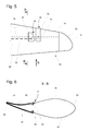
- FIG. 3 schematically the blade tip close range of a wind turbine rotor blade 10 according to the invention with a view of the pressure side 16 is shown.
- the wind turbine rotor blade 10 is flown by the nose edge 22 ago.
- the direction of flow S is indicated by an arrow.
- the rotor blade is provided with an electric heater 30 which is supplied with electric power via a power supply cable 29.
- the power supply cable 29 is an example of a first electric wire and is connected to a blade tip side end of the electric heater 30.
- the wind turbine rotor blade 10 has at the blade tip 14 a lightning protection receptor 24, which is connected to a lightning conductor 26, which leads to the blade root 12.
- a lightning protection receptor 24 which is connected to a lightning conductor 26, which leads to the blade root 12.
- the mutually facing sides of the two electrodes 42, 44 are both arranged obliquely to the direction of flow S, so that the gap between the electrodes 42, 44 and the width X of the flow channel formed by them greatly widens in the flow direction. A possible after a lightning stroke subsequent current in the spark gap 40 therefore safely disappears.
- An Indian FIG. 3 A dashed line edged surface area 56 of the wind turbine rotor blade 10 is provided with a heat resistant coating to prevent damage to the underlying material of the wind turbine rotor blade 10 by the action of heat. In the surface region 56, the two electrodes are arranged.
- a first connection cable 47 is attached to the first electrode 44 via a fastener 46 and connects it to the lightning protection conductor 26.
- a second connection cable 48 is attached to the second electrode 42 via a fastener 46 and connects it to the power supply cable 29 of the electric heater 30.
- the electric heater 30 is galvanically isolated from the lightning conductor 26.
- a spark gap is ignited between the first and the second electrode (44, 42) and an equipotential bonding is created between the lightning protection conductor 26 and the power supply cable 29.
- the first connection cable 47 is an electrical connector, which may also be formed as a solid, conductive connection base. This solution allows for easy Contacting after the connection of two rotor half shells during the production of the wind turbine rotor blade 10.
- FIG. 5 shows a schematic representation of the blade tip near area of another wind turbine rotor blade 10 according to the invention with a view of the pressure side 16. It is flowing from the profile nose edge 22 ago.
- the direction of flow S is indicated by an arrow.
- the wind turbine rotor blade 10 has two lightning protection conductors 50, 52, of which the first lightning protection conductor 50 runs on the suction side and the second lightning protection conductor 52 on the pressure side 16.
- the suction-side first lightning conductor 50 extends from the lightning protection receptor 24 at the blade tip 14 via a contact point at the suction end of the busbar 54 to the blade root. It thus establishes the connection between the first electrode (44) and the lightning protection receptor (24).
- the pressure-side lightning protection conductor 52 is connected to the second electrode 42 on the pressure side.
- FIG. 6 shows a profile view of the wind turbine rotor blade 10 in the sectional plane BB of the Fig. 5 ,
- On the pressure side 16 of the wind turbine rotor blade 10 is an external spark gap 40 having a first electrode 44 which is arranged behind a second electrode 42 hidden.
- the first electrode 44 is part of a bus bar 54 running around the profile end edge 20 of the wind turbine rotor blade 10 and is connected to the first lightning protection conductor 50 on the suction side 18 via fastening means 46.
- the second electrode 42 is connected on the pressure side to the second lightning protection conductor 52, which is an example of a first electrical line.
- FIG. 7 also shows in a schematic representation of the blade tip near area of a third wind turbine rotor blade 10 according to the invention
- the wind turbine rotor blade 10 is flowed by the profile nose edge 22 ago.
- the direction of flow S is indicated by an arrow.
- the wind turbine rotor blade 10 has two lightning protection conductors 50, 52, both of which run on the pressure side 16 in the interior of the wind turbine rotor blade 10.
- the first lightning protection conductor 50 extends to the lightning protection receptor 24 at the blade tip 14 and thus connects the first electrode 44 with the lightning protection receptor 24.
- the lightning protection conductors 50, 52 are each connected to an electrode 42, 44 via fastening means 46.
- the electrodes 42, 44 are according to the embodiment according to Figure 2c arranged.
- a surface portion 56 of the wind turbine rotor blade 10 in which the two electrodes are disposed has a heat-resistant coating.
- FIG. 8 is a section through the wind turbine blade 10 from Fig. 7 shown in the plane CC. It can be seen that first electrode 44 and second electrode 42 partially overlap.
Landscapes
- Engineering & Computer Science (AREA)
- Life Sciences & Earth Sciences (AREA)
- Sustainable Development (AREA)
- Sustainable Energy (AREA)
- Chemical & Material Sciences (AREA)
- Combustion & Propulsion (AREA)
- Mechanical Engineering (AREA)
- General Engineering & Computer Science (AREA)
- Wind Motors (AREA)
Description
- Die Erfindung betrifft ein Windenergieanlagenrotorblatt mit einem Blitzschutzrezeptor, einer ersten elektrischen Leitung und einer Potentialausgleichseinrichtung, die eine erste Elektrode, die mit dem Blitzschutzrezeptor verbunden ist, und eine zweite Elektrode, die mit der ersten elektrischen Leitung verbunden ist, aufweist, wobei zwischen den beiden Elektroden eine Funkenstrecke ausgebildet ist.
- Es ist bekannt, Windenergieanlagenrotorblätter mit einer Blitzschutzeinrichtung vor Schäden durch Blitzschlag zu bewahren. Hierzu wird in der Regel im Bereich der Blattspitze ein Blitzschutzrezeptor angeordnet. Der Strom eines in den Blitzschutzrezeptor einschlagenden Blitzes wird dann über einen Blitzschutzleiter zur Blattwurzel hin und von dort über die Gondel und den Turm der Windenergieanlage in den Erdboden abgeleitet. Sind in dem Windenergieanlagenrotorblatt mehrere elektrisch leitfähige Elemente mehr oder weniger parallel angeordnet, kommt es durch elektromagnetische Induktion bei einem Blitzschlag zu großen Potentialdifferenzen zwischen den elektrisch leitfähigen Elementen, die zu Überschlägen oder gar zur Zerstörung des Windenergieanlagenrotorblatts führen können. Es ist bekannt, derartigen Überschlägen durch Potentialausgleichselemente entgegenzuwirken.
- Ein solcher Potentialausgleich ist insbesondere erforderlich, wenn eines der elektrisch leitfähigen Elemente eine elektrische Heizeinrichtung zum Enteisen der Oberfläche des Windenergieanlagenrotorblattes ist. Diese Heizeinrichtungen sind mit einer Stromversorgung versehen und müssen im Betrieb elektrisch vom Blitzschutzsystem getrennt sein. Hierzu können im Inneren des Rotorblatts Funkenstrecken zwischen der Heizeinrichtung und der Blitzschutzeinrichtung vorgesehen sein, wie in der Druckschrift
WO 00/79128 A1 - Die Druckschrift
WO 2014/023734 A1 zeigt ein Windenergieanlagenrotorblatt mit einer elektrischen Heizeinrichtung und einem Blitzschutzleiter. Die Heizeinrichtung und der Blitzschutzleiter sind über die Länge des Rotorblatts an mehreren Stellen über Funkenstrecken miteinander verbunden. Die Funkenstrecken sind im Inneren des Rotorblatts in Kombination mit den Blitzschutzrezeptoren angeordnet. - Um die Betriebssicherheit der Blitzschutzeinrichtung zu gewährleisten, muss die Funktionsfähigkeit der Funkenstrecken regelmäßig überprüft werden. Insbesondere im Blattspitzenbereich angeordnete Funkenstrecken sind dabei nur sehr schwer zugänglich.
- Davon ausgehend ist es Aufgabe der Erfindung, ein Windenergieanlagenrotorblatt mit einer Potentialausgleichseinrichtung zur Verfügung zu stellen, das einfacher in einem betriebssicheren Zustand gehalten werden kann.
- Diese Aufgabe wird gelöst durch das Windenergieanlagenrotorblatt mit den Merkmalen des Anspruchs 1. Vorteilhafte Ausgestaltungen sind in den sich anschließenden Unteransprüchen angegeben.
- Das Windenergieanlagenrotorblatt hat einen Blitzschutzrezeptor, eine erste elektrische Leitung und eine Potentialausgleichseinrichtung, die eine erste Elektrode, die mit dem Blitzschutzrezeptor verbunden ist, und eine zweite Elektrode, die mit der ersten elektrischen Leitung verbunden ist, aufweist, wobei zwischen den beiden Elektroden eine Funkenstrecke ausgebildet ist und einander zugewandte Seiten der beiden Elektroden einen Strömungskanal bilden, der so angeordnet ist, dass er von der im Betrieb des Windenergieanlagenrotorblatts anströmenden Umgebungsluft durchströmt wird.
- Der Blitzschutzrezeptor kann insbesondere an oder nahe einer Blattspitze des Windenergieanlagenrotorblatts angeordnet sein, aber auch in einem größeren Abstand davon, auch in Kombination mit einem oder mehreren weiteren Blitzschutzrezeptoren. Er besteht in der Regel aus Metall, beispielsweise aus Kupfer oder Aluminium, und bietet eine an der Außenseite des Windenergieanlagenrotorblatts freiliegende Fläche, in die ein Blitz einschlagen kann.
- Die erste elektrische Leitung kann ein Blitzschutzleiter sein oder eine sonstige elektrische Leitung, beispielsweise eine Versorgungsleitung, mit der einem in oder an dem Windenergieanlagenrotorblatt angeordneten, elektrischen Verbraucher elektrische Energie zugeführt werden kann, oder eine Signalleitung, über die elektrische Signale beispielsweise von einem in oder an dem Windenergieanlagenrotorblatt angeordneten Sensor übertragen werden können. Die erste elektrische Leitung kann so dimensioniert sein, dass sie im Falle eines Blitzschlags, bei dem es zu einem Potentialausgleich über die Funkenstrecke kommt, einen Blitzstrom ganz oder teilweise tragen kann, insbesondere bis zu einer Blattwurzel. In diesem Sinne kann es sich bei der ersten elektrischen Leitung um einen Blitzschutzleiter handeln, auch wenn die erste elektrische Leitung im normalen Betrieb des Windenergieanlagenrotorblatts eine andere Funktion erfüllt. Die erste elektrische Leitung ist von dem Blitzschutzrezeptor galvanisch getrennt. Erst im Falle eines Blitzschlags kommt es zu einem Potentialausgleich über die Funkenstrecke.
- Bei der Verbindung der ersten Elektrode mit dem Blitzschutzrezeptor und/oder bei der Verbindung der zweiten Elektrode mit der ersten elektrischen Leitung kann es sich um eine mittelbare oder unmittelbare Verbindung handeln. Beispielsweise kann diese Verbindung einen starren elektrischen Leiter, ein mehr oder weniger flexibles Kabel und/oder eine Schraubverbindung enthalten.
- Die beiden Elektroden sind bevorzugt massive Metallteile, insbesondere bestehend aus Kupfer. Die beiden Elektroden sind in einem Abstand voneinander angeordnet, der so bemessen ist, dass es bei den bei einem Blitzschlag auftretenden, hohen Potentialdifferenzen zu einem Überschlag kommt, wobei der Abstand gleichzeitig eine ausreichende elektrische Isolation für die im normalen Betrieb des Windenergieanlagenrotorblatts auftretenden Potentialdifferenzen gewährleistet. Typischerweise kann der Abstand zwischen den beiden Elektroden in der Größenordnung von etwa einem oder mehreren Zentimetern liegen. Die beiden einander zugewandten Seiten der Elektroden können parallel zueinander ausgerichtete Flächen aufweisen, aber auch in einem Winkel zueinander angeordnet sein.
- Bei der Erfindung bilden die einander zugewandten Seiten der beiden Elektroden einen Strömungskanal, der so angeordnet ist, dass er von der im Betrieb des Windenergieanlagenrotorblatts anströmenden Umgebungsluft durchströmt wird. Der Strömungskanal zwischen den beiden Elektroden ist ein Freiraum, der von der Umgebungsluft durchströmt wird. Er wird seitlich ganz oder teilweise von den beiden Elektroden begrenzt und kann zu einer oder mehreren weiteren Seiten offen oder von anderen Elementen, beispielsweise einer Außenseite des Windenergieanlagenrotorblatts, begrenzt sein. Kommt es infolge eines Blitzschlags zu einem Überschlag zwischen den beiden Elektroden, bildet sich zwischen den beiden einander zugewandten Seiten der Elektroden ein Lichtbogen aus, der den Strömungskanal kreuzt und im Wesentlichen quer zu einer Strömungsrichtung in dem Strömungskanal ausgerichtet ist.
- Die Ausbildung eines Strömungskanals zwischen den beiden Elektroden hat zwei die dauerhafte und einwandfreie Funktionsfähigkeit der Funkenstrecke fördernde Wirkungen: Zum einen bewirkt die Durchströmung des Strömungskanals einen Selbstreinigungseffekt. Feuchtigkeit oder Partikel werden durch die hohen Strömungsgeschwindigkeiten weitgehend selbsttätig entfernt. Zum anderen verhindert die Luftströmung im Strömungskanal, dass ein infolge eines Blitzschlags übergesprungener Funken von einer Potentialdifferenz zwischen dem Blitzschutzrezeptor und der ersten elektrischen Leitung aufrechterhalten wird. Dies kann passieren, wenn die Potentialdifferenz zwischen den beiden Elektroden im normalen Betrieb höher ist als die Lichtbogenspannung. Dabei ist die Lichtbogenspannung durch die Ionisation der Luft wesentlich geringer als die für einen Überschlag erforderliche Zündspannung. Die starke Luftströmung kühlt den Lichtbogen und führt ihn in Richtung des Strömungskanals nach hinten, was zu einem zuverlässigen Erlöschen des Funkens/Lichtbogens führt.
- In einer Ausgestaltung ist der Strömungskanal an einer der anströmenden Umgebungsluft ausgesetzten Außenseite des Windenergieanlagenrotorblatts angeordnet. Insbesondere kann der Strömungskanal auf seiner von der Außenseite des Windenergieanlagenrotorblatts abgewandten Seite offen sein, sodass er von außen unmittelbar zugänglich ist. Grundsätzlich kann der Strömungskanal auch ganz oder teilweise in das Windenergieanlagenrotorblatt integriert sein. Eine außenliegende Anordnung führt jedoch zu einer besonders wirksamen Durchströmung des Strömungskanals und vereinfacht den Zugang zu Wartungs- und Reparaturzwecken.
- In einer Ausgestaltung ist der Strömungskanal an einer Druckseite des Windenergieanlagenrotorblatts angeordnet. Grundsätzlich kann der Strömungskanal auch an der Saugseite angeordnet sein. Im Betrieb des Windenergieanlagenrotorblatts bilden sich an der Druckseite jedoch besonders stabile Strömungsverhältnisse aus, da Turbulenzen oder Strömungsablösungen kaum auftreten. Der Strömungskanal wird daher an der Druckseite bei unterschiedlichen Betriebsbedingungen besonders wirksam durchströmt.
- In einer Ausgestaltung weist der Strömungskanal eine Längsrichtung auf, die in Richtung der anströmenden Umgebungsluft ausgerichtet ist. Diese Maßnahme begünstigt ebenfalls eine gleichmäßige Durchströmung des Strömungskanals.
- In einer Ausgestaltung weitet sich der Strömungskanal in Richtung der ihn durchströmenden Luft auf. Dabei vergrößert sich der Abstand zwischen der ersten Elektrode und der zweiten Elektrode in Richtung der den Strömungskanal durchströmenden Luftströmung. Nach dem Zünden eines Lichtbogens bewirkt diese Strömung ein Wandern des Lichtbogens. Mit größer werdendem Abstand zwischen den Elektroden erhöht sich die Lichtbogenspannung, was zu einem Erlöschen des Funkens führt, sobald die Lichtbogenspannung über der Potentialdifferenz zwischen den beiden Elektroden liegt. Dadurch wird das Erlöschen des Funkens noch zuverlässiger erreicht.
- In einer Ausgestaltung weisen die erste Elektrode und/oder die zweite Elektrode eine scheibenförmige Grundform auf. Insbesondere können sie aus einer Metallplatte mit im Wesentlichen gleichmäßiger Stärke bestehen. Dadurch können die Elektroden besonders einfach befestigt werden, insbesondere an einer Außenseite des Windenergieanlagenrotorblatts, wobei sie eine ausreichende Stromtragfähigkeit aufweisen und die Strömungsverhältnisse am Rotorblatt relativ wenig beeinflussen.
- In einer Ausgestaltung weisen die erste Elektrode und/oder die zweite Elektrode eine an der Außenseite des Windenergieanlagenrotorblatts anliegende Unterseite und eine oder mehrere, relativ zu der Unterseite schräg angeordnete Seitenflächen auf. Mit zunehmendem Abstand von der Unterseite können sich die Abmessungen der Elektroden durch die schräg angeordneten Seitenflächen verkleinern. Schräg angeordnete Seitenflächen sind aerodynamisch vorteilhaft. Auch die einander zugewandten Seiten der beiden Elektroden können schräg angeordnet sein, sodass der zwischen ihnen gebildete Strömungskanal im Querschnitt im Wesentlichen trapezförmig ist.
- In einer Ausgestaltung weist das Windenergieanlagenrotorblatt eine elektrische Heizeinrichtung auf und die erste elektrische Leitung ist eine Versorgungsleitung, über die die elektrische Heizeinrichtung mit einem Heizstrom versorgt werden kann. In diesem Fall ermöglicht die galvanische Trennung zwischen der ersten elektrischen Leitung und dem Blitzschutzrezeptor, der in der Regel über einen Blitzschutzleiter geerdet ist, eine zuverlässige Bestromung der Heizeinrichtung. Gleichzeitig werden Beschädigungen an der Versorgungsleitung oder an der elektrischen Heizeinrichtung durch den im Falle eines Blitzschlags eintretenden Potentialausgleich vermieden.
- In einer Ausgestaltung weist das Windenergieanlagenrotorblatt einen Blitzschutzleiter auf, der mit dem Blitzschutzrezeptor verbunden ist und zu einer Blattwurzel führt. Der Blitzschutzleiter ist eine zweite elektrische Leitung und kann gegebenenfalls, wie die erste elektrische Leitung auch, eine Zusatzfunktion erfüllen, etwa als Versorgungs- oder Signalleitung. Hierzu kann der Blitzschutzleiter nötigenfalls galvanisch vom Erdpotential getrennt sein, beispielsweise unter Verwendung einer weiteren Funkenstrecke oder eines sonstigen Überspannungsableiters.
- In einer Ausgestaltung ist der Blitzschutzleiter an der Saugseite des Windenergieanlagenrotorblatts angeordnet und mit der ersten Elektrode über ein im Inneren des Windenergieanlagenrotorblatts angeordnetes, elektrisches Verbindungsstück, das von der Saugseite zu der ersten Elektrode führt, verbunden. Dies ermöglicht eine zuverlässige elektrische Verbindung zwischen dem Blitzschutzleiter und einer an der Druckseite angeordneten ersten Elektrode. Das elektrische Verbindungsstück kann insbesondere beim Verbinden einer druckseitigen und einer saugseitigen Rotorblatthalbschale montiert werden, wobei der Blitzschutzleiter bereits vorher in die saugseitige Halbschale integriert werden kann.
- In einer Ausgestaltung ist der Blitzschutzleiter an einer Saugseite des Windenergieanlagenrotorblatts angeordnet und mit der ersten Elektrode über eine an einer Außenseite des Windenergieanlagenrotorblatts angeordnete Stromschiene verbunden. Mit Hilfe einer solchen Stromschiene kann ebenfalls eine zuverlässige elektrische Verbindung zwischen dem Blitzschutzleiter an der Saugseite und einer auf der Druckseite angeordneten ersten Elektrode hergestellt werden, insbesondere nach dem Verbinden zweier Rotorblatthalbschalen.
- In einer Ausgestaltung ist die Stromschiene um eine Profilendkante des Windenergieanlagenrotorblatts herumgeführt. Dadurch wird eine unerwünschte Wechselwirkung zwischen der Stromschiene und einer vorwiegend im Bereich einer Profilnasenkante angeordneten, elektrischen Heizeinrichtung vermieden.
- In einer Ausgestaltung ist die erste Elektrode von einem von dem Blitzschutzleiter entfernten Ende der Stromschiene gebildet. Stromschiene und erste Elektrode sind somit ein einheitliches Bauteil. Beispielsweise kann die Stromschiene aus einem massiven Metallstreifen oder -band hergestellt sein. Die Fertigung einer gesonderten, ersten Elektrode kann entfallen, ebenso wie das Herstellen einer Verbindung zwischen der ersten Elektrode und der Stromschiene.
- In einer Ausgestaltung ist ein Oberflächenbereich an der Außenseite des Windenergieanlagenrotorblatts, in dem die beiden Elektroden angeordnet sind, mit einer hitzebeständigen Beschichtung versehen. Die Beschichtung dient beim Zünden der Funkenstrecke als Schutzschicht für das Material der Rotorblattschale (zum Beispiel ein Glasfaserlaminat) und kann beispielsweise aus Keramik oder Teflon bestehen.
- Die Erfindung wird nachfolgend anhand von in Figuren dargestellten Ausführungsbeispielen näher erläutert. Es zeigen:
- Fig. 1
- ein aus dem Stand der Technik bekanntes Rotorblatt in einer vereinfachten, perspektivischen Darstellung,
- Fig.2a-c
- Detaildarstellungen von erfindungsgemäßen Funkenstrecken in drei Ausführungsformen,
- Fig. 3
- den Blattspitzenbereich eines ersten erfindungsgemäßen Windenergieanlagenrotorblatts in einer Ansicht auf die Druckseite,
- Fig. 4
- den Blattspitzenbereich aus
Figur 3 in einer Schnittdarstellung entlang der inFigur 3 mit A-A bezeichneten Ebene von der Profilnasenkante aus gesehen, - Fig. 5
- den Blattspitzenbereich eines zweiten erfindungsgemäßen Windenergieanlagenrotorblatts in einer Ansicht auf die Druckseite,
- Fig. 6
- den Blattspitzenbereich aus
Figur 5 in einer Schnittdarstellung entlang der inFigur 5 mit B-B bezeichneten Ebene von der Blattspitze aus gesehen, - Fig. 7
- den Blattspitzenbereich eines dritten erfindungsgemäßen Windenergieanlagenrotorblatts in einer Ansicht auf die Druckseite und
- Fig. 8
- den Blattspitzenbereich aus
Figur 7 in einer Schnittdarstellung entlang der inFigur 7 mit C-C bezeichneten Ebene von der Blattspitze aus gesehen. - Alle Figuren sind schematische Darstellungen und verwenden für einander entsprechende Elemente die gleichen Bezugszeichen.
- Die
Figur 1 zeigt ein aus dem Stand der Technik bekanntes Windenergieanlagenrotorblatt 10 mit einer elektrischen Heizeinrichtung 30. Das Windenergieanlagenrotorblatt 10 hat eine Blattwurzel 12 und eine Blattspitze 14. In derFigur 1 ist der Blick im Wesentlichen auf die Druckseite 16 gerichtet. Auf der vom Betrachter abgewandten Seite hat das Windenergieanlagenrotorblatt 10 eine Saugseite 18. - Das Windenergieanlagenrotorblatt 10 hat eine Profilendkante 20 und eine Profilnasenkante 22. Im Bereich der Blattspitze 14 ist ein Blitzschutzrezeptor 24 angeordnet, der mit einem gestrichelt angedeuteten Blitzschutzleiter 26 elektrisch leitend verbunden ist. Über den Blitzschutzleiter 26 kann der Strom eines in den Blitzschutzrezeptor 24 einschlagenden Blitzes in Richtung zur Blattwurzel 12 hin abgeleitet werden.
- Das Windenergieanlagenrotorblatt 10 weist eine in Längsrichtung vom Strom durchflossene, elektrische Heizeinrichtung 30 auf, welche an ihrem blattwurzelseitigen Ende und an ihrem blattspitzenseitigen Ende jeweils mit einem Stromversorgungskabel 28, 29 verbunden ist. Zwischen der Heizeinrichtung 30 und dem Blitzschutzleiter 26 sowie zwischen den Stromversorgungskabeln 28, 29 und dem Blitzschutzleiter 26 befinden sich Potentialausgleichsverbindungen 32, die jeweils eine zwischengeschaltete Funkenstrecke 34 aufweisen. Im Bereich der Rotorblattspitze ist eine auf der Rotorblattoberfläche liegende erfindungsgemäße Potentialausgleichsvorrichtung angeordnet, welche als Stromschiene 54 mit zwei Elektroden ausgebildet ist, zwischen denen sich eine Funkenstrecke 40 befindet. Im normalen Betrieb sind die Heizeinrichtung 30 und der Blitzschutzleiter 26 galvanisch voneinander getrennt, um das Abfließen des Heizstroms über den Blitzschutzleiter 26 zu verhindern. Im Fall eines Blitzschlags werden die Funkenstrecken 34, 40 vom Blitzstrom gezündet und es erfolgt ein Potentialausgleich zwischen den parallelen Leitern.
- In den
Figuren 2a-c sind Detaildarstellungen von drei Ausführungsformen erfindungsgemäßer, außenliegender Funkenstrecken 40 zu sehen. Die Funkenstrecken 40 bestehen in allen drei Ausführungsformen aus einer ersten Elektrode 44 und einer zweiten Elektrode 42. Jede der beiden Elektroden 42, 44 wird über ein Befestigungsmittel 46 mit einem Blitzschutzleiter oder einem anderen elektrischen Leiter (inFigur 2 nicht dargestellt) verbunden. Bei der Ausführungsform nachFig. 2a befindet sich die Kontaktstelle mit dem elektrischen Leiter am anderen Ende der Stromschiene (nicht dargestellt). Bei den Befestigungsmitteln 46 kann es sich zum Beispiel um Gewindebolzen handeln, die in die Bohrungen 45 in den Elektroden 42, 44 eingesetzt werden können. Auf diese Weise können die Elektroden 42, 44 auch an einem Windenergieanlagenrotorblatt 10 befestigt werden. Wie inFig. 2a beispielhaft dargestellt, können die Bohrungen 45 auch als Langloch ausgebildet sein, um den Abstand X zwischen den Elektroden 42, 44 einstellen zu können. - Die Elektroden 42, 44 werden an einer Außenseite des Windenergieanlagenrotorblatts 10, auf der Oberfläche, angeordnet, bevorzugt an der Druckseite, da diese weniger anfällig für aerodynamische Störungen ist. Der Abstand X zwischen den Elektroden 42, 44 ist so bemessen, dass die Funkenstrecke nur beim Auftreten hoher Spannungen, wie sie bei einem Blitzschlag auftreten, zündet. Bei niedrigen Spannungen, wie sie beispielsweise zur Versorgung einer Heizeinrichtung verwendet werden, zündet die Funkenstrecke nicht und die beiden Elektroden 42, 44 bleiben elektrisch voneinander getrennt.
- Die Elektroden 42, 44 können so positioniert werden, dass der Spalt zwischen den Elektroden parallel zur Anströmrichtung S verläuft. Auf diese Weise kann der Zwischenraum zwischen den Elektroden ständig von anhaftenden Partikeln, wie Sand oder Staub, befreit werden.
- Zwischen den einander zugewandten Seiten der Elektroden 42, 44 ist ein Strömungskanal gebildet, der von der anströmenden Luft durchströmt wird. Der Strömungskanal ist an einer Seite von der druckseitigen Oberfläche des Windenergieanlagenrotorblatts 10 begrenzt. Die einander zugewandten Seiten der Elektroden 42, 44 bilden seitliche Begrenzungen des Strömungskanals. An der von der Oberfläche des Windenergieanlagenrotorblatts 10 abgewandten Seite ist der Strömungskanal offen, ebenso vom und hinten, wo die anströmende Luft ein- bzw. ausströmen kann. Der Strömungskanal weist eine Längsrichtung auf, die im Wesentlichen der Anströmrichtung S entspricht.
- Des Weiteren sind die Elektroden 42, 44 geometrisch so gestaltet, dass sich der Abstand X zwischen den gegenüberliegenden Kanten der Elektroden und somit die Länge der Funkenstrecke in Anströmrichtung S vergrößert. Der von den Elektroden 42, 44 gebildete Strömungskanal weitet sich in Strömungsrichtung entsprechend auf. Durch die senkrecht zur Funkenstrecke verlaufende Luftströmung und den sich vergrößernden Abstand X wird nach dem Zünden des Lichtbogens ein Wandern des Lichtbogens in Anströmrichtung S hervorgerufen. Mit größer werdendem Abstand zwischen den Elektroden 42, 44 erhöht sich die Lichtbogenspannung, was zu einem Erlöschen des Funkens führt, sobald die Lichtbogenspannung über der anliegenden Netzspannung (die zum Beispiel zum Betrieb einer Heizeinrichtung vorgesehen ist) liegt. Zudem führt die Strömung entlang der Funkenstrecke zu einer Kühlung des Lichtbogens, was eine weitere Erhöhung der Lichtbogenspannung bewirkt.
- In den
Figuren 2a-c haben die Elektroden 42, 44 jeweils eine scheiben- oder plattenförmige Grundform. InFigur 2a weist die zweite Elektrode 42 eine in etwa rechteckige Form auf, während die erste Elektrode 44 trapezförmig ist. Durch die zur zweiten Elektrode 42 weisende, schräge Kante der ersten Elektrode 44 erweitert sich der Spalt X zwischen den Elektroden 42, 44 in Strömungsrichtung. - In
Figur 2b weisen beide Elektroden 42, 44 eine trapezförmige Gestalt auf. Die schrägen Seiten der Trapeze stehen einander gegenüber, so dass wiederum ein sich in Anströmrichtung S verbreiternder Spalt entsteht. Da beide Seiten schräg verlaufen, nimmt die Breite des Spalts schneller zu als im Beispiel derFigur 2a . -
Figur 2c zeigt eine dritte Ausführungsform einer erfindungsgemäßen Funkenstrecke. Die trapezförmigen Elektroden 42, 44 sind doppelt gespiegelt (punktsymmetrisch) zueinander angeordnet. In einem Überlappungsbereich entsteht ein etwa in Anströmrichtung S verlaufender Strömungskanal. Durch das Maß der Überlappung kann der Bereich, in dem die Funkenstrecke zündet, gezielt eingestellt werden. - In der
Figur 3 ist schematisch der blattspitzennahe Bereich eines erfindungsgemäßen Windenergieanlagenrotorblatts 10 mit Blick auf die Druckseite 16 dargestellt. Das Windenergieanlagenrotorblatt 10 wird von der Nasenkante 22 her angeströmt. Die Anströmrichtung S ist durch einen Pfeil gekennzeichnet. - Das Rotorblatt ist mit einer elektrischen Heizeinrichtung 30 versehen, die über ein Stromversorgungskabel 29 mit elektrischem Strom versorgt wird. Das Stromversorgungskabel 29 ist ein Beispiel einer ersten elektrischen Leitung und ist mit einem blattspitzenseitigen Ende der elektrischen Heizeinrichtung 30 verbunden.
- Das Windenergieanlagenrotorblatt 10 weist an der Blattspitze 14 einen Blitzschutzrezeptor 24 auf, welcher mit einem Blitzschutzleiter 26, der zur Blattwurzel 12 führt, verbunden ist. Auf der Druckseite 16 des Windenergieanlagenrotorblatts 10 befindet sich eine außenliegende Funkenstrecke 40 mit einer ersten Elektrode 44 und einer zweiten Elektrode 42. Die einander zugewandten Seiten der beiden Elektroden 42, 44 sind beide schräg zur Anströmrichtung S angeordnet, so dass sich der Spalt zwischen den Elektroden 42, 44 bzw. die Breite X des von ihnen gebildeten Strömungskanals in Strömungsrichtung stark aufweitet. Ein nach einem Blitzschlag möglicher Folgestrom in der Funkenstrecke 40 verlischt daher sicher.
- Ein in der
Figur 3 von einer gestrichelten Linie umrandeter Oberflächenbereich 56 des Windenergieanlagenrotorblatts 10 ist mit einer hitzebeständigen Beschichtung versehen, um eine Beschädigung des darunterliegenden Materials der Windenergieanlagenrotorblatts 10 durch Hitzeeinwirkung zu verhindern. In dem Oberflächenbereich 56 sind die beiden Elektroden angeordnet. - Ein erstes Verbindungskabel 47 ist über ein Befestigungsmittel 46 an der ersten Elektrode 44 befestigt und verbindet diese mit dem Blitzschutzleiter 26. Ein zweites Verbindungskabel 48 ist über ein Befestigungsmittel 46 an der zweiten Elektrode 42 befestigt und verbindet diese mit dem Stromversorgungskabel 29 der elektrischen Heizeinrichtung 30. Im normalen Heizbetrieb ist die elektrische Heizeinrichtung 30 von dem Blitzschutzleiter 26 galvanisch getrennt. Im Fall eines Blitzschlags wird zwischen der ersten und der zweiten Elektrode (44, 42) eine Funkenstrecke gezündet und es entsteht ein Potentialausgleich zwischen dem Blitzschutzleiter 26 und dem Stromversorgungskabel 29.
- Zur besseren Veranschaulichung zeigt die
Figur 4 den Blattspitzenbereich ausFig. 3 entlang dem Schnitt A-A von der Profilnasenkante 22 aus gesehen. Die Anströmrichtung S verläuft in die Betrachtungsebene hinein. Das erste Verbindungskabel 47 ist ein elektrisches Verbindungsstück, das auch als feste, leitfähige Verbindungsbasis ausgebildet sein kann. Diese Lösung ermöglicht eine einfache Kontaktierung nach dem Verbinden zweier Rotorblatthalbschalen bei der Fertigung des Windenergieanlagenrotorblatts 10. - Die
Figur 5 zeigt in einer schematischen Darstellung den blattspitzennahen Bereich eines weiteren, erfindungsgemäßen Windenergieanlagenrotorblatts 10 mit Blick auf die Druckseite 16. Es wird von der Profilnasenkante 22 her angeströmt. Die Anströmrichtung S ist durch einen Pfeil gekennzeichnet. Das Windenergieanlagenrotorblatt 10 weist zwei Blitzschutzleiter 50, 52 auf, von denen der erste Blitzschutzleiter 50 auf der Saugseite und der zweite Blitzschutzleiter 52 auf der Druckseite 16 verläuft. Der saugseitige erste Blitzschutzleiter 50 verläuft vom Blitzschutzrezeptor 24 an der Blattspitze 14 über eine Kontaktstelle am saugseitigen Ende der Stromschiene 54 bis zur Blattwurzel. Er stellt somit die Verbindung zwischen der ersten Elektrode (44) und dem Blitzschutzrezeptor (24) her. Der druckseitige Blitzschutzleiter 52 ist mit der zweiten Elektrode 42 auf der Druckseite verbunden. - Die
Figur 6 zeigt eine Profilansicht des Windenergieanlagenrotorblatts 10 in der Schnittebene B-B aus derFig. 5 . Auf der Druckseite 16 des Windenergieanlagenrotorblatts 10 befindet sich eine außenliegende Funkenstrecke 40 mit einer ersten Elektrode 44, die verdeckt hinter einer zweiten Elektrode 42 angeordnet ist. Die erste Elektrode 44 ist Teil einer um die Profilendkante 20 des Windenergieanlagenrotorblatts 10 herum verlaufenden Stromschiene 54 und auf der Saugseite 18 über Befestigungsmittel 46 mit dem ersten Blitzschutzleiter 50 verbunden. Die zweite Elektrode 42 ist auf der Druckseite mit dem zweiten Blitzschutzleiter 52, der ein Beispiel einer ersten elektrischen Leitung ist, in Verbindung. - Die
Figur 7 zeigt ebenfalls in einer schematischen Darstellung den blattspitzennahen Bereich eines dritten, erfindungsgemäßen Windenergieanlagenrotorblatts 10 mit - Blick auf die Druckseite 16. Das Windenergieanlagenrotorblatt 10 wird von der Profilnasenkante 22 her angeströmt. Die Anströmrichtung S ist durch einen Pfeil gekennzeichnet. Das Windenergieanlagenrotorblatt 10 weist zwei Blitzschutzleiter 50, 52 auf, die beide auf der Druckseite 16 im Inneren des Windenergieanlagenrotorblatts 10 verlaufen. Der erste Blitzschutzleiter 50 verläuft bis zum Blitzschutzrezeptor 24 an der Blattspitze 14 und verbindet somit die erste Elektrode 44 mit dem Blitzschutzrezeptor 24. Die Blitzschutzleiter 50, 52 sind jeweils mit einer Elektrode 42, 44 über Befestigungsmittel 46 verbunden. Die Elektroden 42, 44 sind entsprechend der Ausführungsform nach
Figur 2c angeordnet. - Auch in der
Figur 7 weist ein Oberflächenbereich 56 des Windenergieanlagenrotorblatts 10, in dem die beiden Elektroden angeordnet sind, eine hitzebeständige Beschichtung auf. - In der
Figur 8 ist ein Schnitt durch das Windenergieanlagenrotorblatt 10 ausFig. 7 in der Ebene C-C dargestellt. Man erkennt, dass sich erste Elektrode 44 und zweite Elektrode 42 teilweise überlappen. -
- 10
- Windenergieanlagenrotorblatt
- 12
- Blattwurzel
- 14
- Blattspitze
- 16
- Druckseite
- 18
- Saugseite
- 20
- Profilendkante
- 22
- Profilnasenkante
- 24
- Blitzschutzrezeptor
- 26
- Blitzschutzleiter
- 28
- Stromversorgungskabel
- 29
- Stromversorgungskabel
- 30
- Heizeinrichtung
- 32
- Potentialausgleichsverbindung
- 34
- Funkenstrecke
- 40
- außen liegende Funkenstrecke
- 42
- zweite Elektrode
- 44
- erste Elektrode
- 45
- Bohrung
- 46
- Befestigungsmittel
- 47
- erstes Verbindungskabel
- 48
- zweites Verbindungskabel
- 50
- erster Blitzschutzleiter
- 52
- zweiter Blitzschutzleiter
- 54
- Stromschiene
- 56
- Oberflächenbereich mit Beschichtung
- S
- Anströmrichtung
- X
- Abstand
Claims (14)
- Windenergieanlagenrotorblatt (10) mit einem Blitzschutzrezeptor (24), einer ersten elektrischen Leitung und einer Potentialausgleichseinrichtung, die eine erste Elektrode (44), die mit dem Blitzschutzrezeptor (24) verbunden ist, und eine zweite Elektrode (42), die mit der ersten elektrischen Leitung verbunden ist, aufweist, wobei zwischen den beiden Elektroden (42, 44) eine Funkenstrecke (40) ausgebildet ist, dadurch gekennzeichnet, dass einander zugewandte Seiten der beiden Elektroden (42, 44) einen Strömungskanal bilden, der so angeordnet ist, dass er von der im Betrieb des Windenergieanlagenrotorblatts (10) anströmenden Umgebungsluft durchströmt wird.
- Windenergieanlagenrotorblatt (10) nach Anspruch 1, dadurch gekennzeichnet, dass der Strömungskanal an einer der anströmenden Umgebungsluft ausgesetzten Außenseite des Windenergieanlagenrotorblatts (10) angeordnet ist.
- Windenergieanlagenrotorblatt (10) nach Anspruch 1 oder 2, dadurch gekennzeichnet, dass der Strömungskanal an einer Druckseite (16) des Windenergieanlagenrotorblatts (10) angeordnet ist.
- Windenergieanlagenrotorblatt (10) nach einem der Ansprüche 1 bis 3, dadurch gekennzeichnet, dass der Strömungskanal eine Längsrichtung aufweist, die in Richtung der anströmenden Umgebungsluft ausgerichtet ist.
- Windenergieanlagenrotorblatt (10) nach einem der Ansprüche 1 bis 4, dadurch gekennzeichnet, dass sich der Strömungskanal in Richtung der ihn durchströmenden Luft aufweitet.
- Windenergieanlagenrotorblatt (10) nach einem der Ansprüche 1 bis 5, dadurch gekennzeichnet, dass die erste Elektrode (44) und/oder die zweite Elektrode (42) eine scheibenförmige Grundform aufweisen.
- Windenergieanlagenrotorblatt (10) nach einem der Ansprüche 1 bis 6, dadurch gekennzeichnet, dass die erste Elektrode (44) und/oder die zweite Elektrode (42) eine an der Außenseite des Windenergieanlagenrotorblatts (10) anliegende Unterseite und eine oder mehrere, relativ zu der Unterseite schräg angeordnete Seitenflächen aufweisen.
- Windenergieanlagenrotorblatt (10) nach einem der Ansprüche 1 bis 7, dadurch gekennzeichnet, dass das Windenergieanlagenrotorblatt (10) eine elektrische Heizeinrichtung (30) aufweist und die erste elektrische Leitung eine Versorgungsleitung ist, über die die elektrische Heizeinrichtung (30) mit einem Heizstrom versorgt werden kann.
- Windenergieanlagenrotorblatt (10) nach einem der Ansprüche 1 bis 8, dadurch gekennzeichnet, dass das Windenergieanlagenrotorblatt (10) einen Blitzschutzleiter (26) aufweist, der mit dem Blitzschutzrezeptor (24) verbunden ist und zu einer Blattwurzel (12) führt.
- Windenergieanlagenrotorblatt (10) nach Anspruch 9, dadurch gekennzeichnet, dass der Blitzschutzleiter (26) an der Saugseite (18) des Windenergieanlagenrotorblatts (10) angeordnet ist und mit der ersten Elektrode (44) über ein im Inneren des Windenergieanlagenrotorblatts (10) angeordnetes, elektrisches Verbindungsstück, das von der Saugseite (18) zu der ersten Elektrode (44) führt, verbunden ist.
- Windenergieanlagenrotorblatt (10) nach Anspruch 9, dadurch gekennzeichnet, dass der Blitzschutzleiter (26) an der Saugseite (18) des Windenergieanlagenrotorblatts (10) angeordnet ist und mit der ersten Elektrode (44) über eine an der Außenseite des Windenergieanlagenrotorblatts (10) angeordnete Stromschiene (54) verbunden ist.
- Windenergieanlagenrotorblatt (10) nach Anspruch 11, dadurch gekennzeichnet, dass die Stromschiene (54) um eine Profilendkante (20) des Windenergieanlagenrotorblatts (10) herumgeführt ist.
- Windenergieanlagenrotorblatt (10) nach Anspruch 11 oder 12, dadurch gekennzeichnet, dass die erste Elektrode (44) von einem von dem Blitzschutzleiter (26) entfernten Ende der Stromschiene (54) gebildet ist.
- Windenergieanlagenrotorblatt (10) nach einem der Ansprüche 1 bis 13, dadurch gekennzeichnet, dass ein Oberflächenbereich (56) an der Außenseite des Windenergieanlagenrotorblatts (10), in dem die beiden Elektroden angeordnet sind, mit einer hitzebeständigen Beschichtung versehen ist.
Priority Applications (4)
| Application Number | Priority Date | Filing Date | Title |
|---|---|---|---|
| EP15180399.6A EP3130800B8 (de) | 2015-08-10 | 2015-08-10 | Windenergieanlagenrotorblatt mit einer funkenstrecke |
| DK15180399.6T DK3130800T3 (en) | 2015-08-10 | 2015-08-10 | Wind turbine rotor blade with a spark gap |
| ES15180399.6T ES2667501T3 (es) | 2015-08-10 | 2015-08-10 | Pala de rotor de instalación de energía eólica con un descargador de chispa |
| US15/226,493 US10202966B2 (en) | 2015-08-10 | 2016-08-02 | Wind turbine rotor blade having a spark gap |
Applications Claiming Priority (1)
| Application Number | Priority Date | Filing Date | Title |
|---|---|---|---|
| EP15180399.6A EP3130800B8 (de) | 2015-08-10 | 2015-08-10 | Windenergieanlagenrotorblatt mit einer funkenstrecke |
Publications (3)
| Publication Number | Publication Date |
|---|---|
| EP3130800A1 true EP3130800A1 (de) | 2017-02-15 |
| EP3130800B1 EP3130800B1 (de) | 2018-02-21 |
| EP3130800B8 EP3130800B8 (de) | 2018-04-18 |
Family
ID=53794119
Family Applications (1)
| Application Number | Title | Priority Date | Filing Date |
|---|---|---|---|
| EP15180399.6A Active EP3130800B8 (de) | 2015-08-10 | 2015-08-10 | Windenergieanlagenrotorblatt mit einer funkenstrecke |
Country Status (4)
| Country | Link |
|---|---|
| US (1) | US10202966B2 (de) |
| EP (1) | EP3130800B8 (de) |
| DK (1) | DK3130800T3 (de) |
| ES (1) | ES2667501T3 (de) |
Cited By (1)
| Publication number | Priority date | Publication date | Assignee | Title |
|---|---|---|---|---|
| EP3499020A1 (de) * | 2017-12-13 | 2019-06-19 | Nordex Energy GmbH | Rotorblattschale für ein rotorblatt und verfahren zum herstellen einer rotorblattschale für ein rotorblatt |
Families Citing this family (10)
| Publication number | Priority date | Publication date | Assignee | Title |
|---|---|---|---|---|
| CN107882697A (zh) * | 2017-11-03 | 2018-04-06 | 索爱菊 | 一种风力发电机组叶片防冰除冰系统 |
| EP3879091B1 (de) * | 2020-03-13 | 2024-03-27 | Siemens Gamesa Renewable Energy A/S | Windturbinenrotorblattanordnung und verfahren zur herstellung einer windturbinenrotorblattanordnung |
| EP4019772B1 (de) * | 2020-12-23 | 2024-10-30 | Polytech A/S | Blitzschutzsystem für das rotorblatt einer windturbine |
| GB2602463A (en) * | 2020-12-28 | 2022-07-06 | Blade Dynamics Ltd | Protective cap for a leading edge of a wind turbine blade |
| EP4027010B1 (de) * | 2021-01-12 | 2023-09-06 | Siemens Gamesa Renewable Energy Innovation & Technology S.L. | Rotorblatt für eine windturbine und verfahren zur herstellung einer rotorblatt |
| ES2967537T3 (es) * | 2021-02-02 | 2024-04-30 | Siemens Gamesa Renewable Energy Innovation & Technology SL | Pala para una turbina eólica |
| EP4166780A1 (de) * | 2021-10-13 | 2023-04-19 | Siemens Gamesa Renewable Energy A/S | Blitzschutzsystem für rotorblätter mit funkenstrecken für äquipotentialbindungen |
| WO2023090995A1 (en) * | 2021-11-19 | 2023-05-25 | Petroliam Nasional Berhad (Petronas) | An improved offshore wind turbine |
| WO2024113993A1 (zh) * | 2022-11-30 | 2024-06-06 | 江苏金风科技有限公司 | 叶片、风力发电机组及放电装置 |
| CN116292070A (zh) * | 2022-11-30 | 2023-06-23 | 江苏金风科技有限公司 | 叶片及风力发电机组 |
Citations (5)
| Publication number | Priority date | Publication date | Assignee | Title |
|---|---|---|---|---|
| WO2000079128A1 (en) | 1999-06-21 | 2000-12-28 | Lm Glasfiber A/S | Wind turbine blade with a system for deicing and lightning protection |
| DE102005045579A1 (de) * | 2005-09-23 | 2007-03-29 | Kanazawa Institute Of Technology | Windkraftanlage |
| WO2012055418A1 (en) * | 2010-10-27 | 2012-05-03 | Vestas Wind Systems A/S | A wind turbine lightning protection system and wind turbine blade |
| WO2014023734A1 (de) | 2012-08-06 | 2014-02-13 | Wobben Properties Gmbh | Cfk widerstandsblattheizung |
| EP2806160A1 (de) * | 2013-05-23 | 2014-11-26 | Nordex Energy GmbH | Windenergieanlagenrotorblatt mit einer elektrischen Heizeinrichtung und mehreren Blitzschutzleitern |
Family Cites Families (9)
| Publication number | Priority date | Publication date | Assignee | Title |
|---|---|---|---|---|
| ES2255454B1 (es) * | 2004-12-15 | 2007-07-01 | Gamesa Eolica, S.A. | Sistema pararrayos para pala de aerogenerador. |
| ES2310958B1 (es) * | 2006-09-15 | 2009-11-10 | GAMESA INNOVATION & TECHNOLOGY, S.L. | Pala de aerogenerador optimizada. |
| EP2226497A1 (de) * | 2009-03-06 | 2010-09-08 | Lm Glasfiber A/S | Windturbinenschaufel mit Blitzschutzsystem |
| US20100119370A1 (en) * | 2009-11-17 | 2010-05-13 | Modi Vivendi As | Intelligent and optimized wind turbine system for harsh environmental conditions |
| EP2336560A1 (de) * | 2009-12-15 | 2011-06-22 | Vestas Wind Systems A/S | Blitzenergieübertragungseinheit für ein Windrad |
| EP2601409B1 (de) * | 2010-08-02 | 2014-05-21 | Vestas Wind Systems A/S | Blitzenergieübertragungseinheit für eine windturbine |
| CA2772211C (en) * | 2011-03-22 | 2018-02-27 | Envision Energy (Denmark) Aps | A partial pitch wind turbine blade with lightning protection |
| US8834117B2 (en) * | 2011-09-09 | 2014-09-16 | General Electric Company | Integrated lightning receptor system and trailing edge noise reducer for a wind turbine rotor blade |
| DK3130801T3 (en) * | 2015-08-10 | 2019-04-23 | Nordex Energy Gmbh | Wind turbine rotor blade with a spark gap |
-
2015
- 2015-08-10 DK DK15180399.6T patent/DK3130800T3/en active
- 2015-08-10 ES ES15180399.6T patent/ES2667501T3/es active Active
- 2015-08-10 EP EP15180399.6A patent/EP3130800B8/de active Active
-
2016
- 2016-08-02 US US15/226,493 patent/US10202966B2/en active Active
Patent Citations (5)
| Publication number | Priority date | Publication date | Assignee | Title |
|---|---|---|---|---|
| WO2000079128A1 (en) | 1999-06-21 | 2000-12-28 | Lm Glasfiber A/S | Wind turbine blade with a system for deicing and lightning protection |
| DE102005045579A1 (de) * | 2005-09-23 | 2007-03-29 | Kanazawa Institute Of Technology | Windkraftanlage |
| WO2012055418A1 (en) * | 2010-10-27 | 2012-05-03 | Vestas Wind Systems A/S | A wind turbine lightning protection system and wind turbine blade |
| WO2014023734A1 (de) | 2012-08-06 | 2014-02-13 | Wobben Properties Gmbh | Cfk widerstandsblattheizung |
| EP2806160A1 (de) * | 2013-05-23 | 2014-11-26 | Nordex Energy GmbH | Windenergieanlagenrotorblatt mit einer elektrischen Heizeinrichtung und mehreren Blitzschutzleitern |
Cited By (1)
| Publication number | Priority date | Publication date | Assignee | Title |
|---|---|---|---|---|
| EP3499020A1 (de) * | 2017-12-13 | 2019-06-19 | Nordex Energy GmbH | Rotorblattschale für ein rotorblatt und verfahren zum herstellen einer rotorblattschale für ein rotorblatt |
Also Published As
| Publication number | Publication date |
|---|---|
| DK3130800T3 (en) | 2018-06-06 |
| US10202966B2 (en) | 2019-02-12 |
| US20170045037A1 (en) | 2017-02-16 |
| EP3130800B8 (de) | 2018-04-18 |
| EP3130800B1 (de) | 2018-02-21 |
| ES2667501T3 (es) | 2018-05-11 |
Similar Documents
| Publication | Publication Date | Title |
|---|---|---|
| EP3130800B1 (de) | Windenergieanlagenrotorblatt mit einer funkenstrecke | |
| DE60004831T2 (de) | System zum schutz vor eisbildung und blitzeinschlag für ein windturbinenblatt | |
| EP2806160B1 (de) | Windenergieanlagenrotorblatt mit einer elektrischen Heizeinrichtung und mehreren Blitzschutzleitern | |
| EP3165761B1 (de) | Windenergieanlagenrotorblatt mit einer elektrischen heizeinrichtung | |
| EP2880308B1 (de) | Cfk widerstandsblattheizung | |
| DE602004002482T2 (de) | Verbundstruktur-blitzschlagschutz | |
| EP2930355B1 (de) | Windenergieanlagenrotorblatt mit einem Blitzschutzleiter und einem Potentialausgleichselement | |
| DE69520220T2 (de) | Blitzableiter für windmühlenflügel | |
| EP2930352B1 (de) | Windenergieanlagenrotorblatt mit einer Potentialausgleichsanordnung | |
| DE102010025546A1 (de) | Maschinenhausverkleidung | |
| EP3019744B1 (de) | Rotorblatt mit blitzableiter | |
| EP1626470A2 (de) | Stromverteilungssystem zur elektrischen Versorgung von schienenmontierten Einbauten in einem Flugzeug | |
| DE202018102696U1 (de) | Windkraftanlage und ihre Blattenteisungsvorrichtung | |
| DE102015200370A1 (de) | Windstromerzeuger | |
| DE102017007371A1 (de) | Rotorblatt einer Windenergieanlage und Verfahren zum Nachrüsten einer Blitzschutzeinrichtung eines Rotorblatts | |
| EP0387865A1 (de) | Funkenschutzeinrichtung für isolierte Leitungen, insbesondere Freileitungen | |
| EP2930358B1 (de) | Windenergieanlagenrotorblatt mit einem Potentialausgleichselement | |
| EP3339633A1 (de) | Verfahren zur herstellung einer potentialausgleichsverbindung an einem windenergieanlagenrotorblatt und windenergieanlagenrotorblatt mit einer potentialausgleichsverbindung | |
| EP3130801B1 (de) | Windenergieanlagenrotorblatt mit einer funkenstrecke | |
| EP2708740A1 (de) | Windenergieanlagenrotorblatt mit einer elektrischen Heizeinrichtung und einem Blitzableiter | |
| EP2751888B1 (de) | Sammelschienenkontaktierung mit schienendickenausgleich | |
| DE102011004229A1 (de) | Dehnungsvorrichtung für Stromschienen in Niederspannungs-Schienensystemen zur Verteilung elektrischer Energie und Schienenkasten mit einer solchen Dehnungs-vorrichtung | |
| EP3246562B1 (de) | Blitzrezeptor für ein windenergieanlagenrotorblatt | |
| EP1760855A1 (de) | Blitzstromableitvorrichtung | |
| DE202010013449U1 (de) | Fernsteuerbare Steckdose mit guter Wärmeableitungsauswirkung |
Legal Events
| Date | Code | Title | Description |
|---|---|---|---|
| PUAI | Public reference made under article 153(3) epc to a published international application that has entered the european phase |
Free format text: ORIGINAL CODE: 0009012 |
|
| STAA | Information on the status of an ep patent application or granted ep patent |
Free format text: STATUS: THE APPLICATION HAS BEEN PUBLISHED |
|
| AK | Designated contracting states |
Kind code of ref document: A1 Designated state(s): AL AT BE BG CH CY CZ DE DK EE ES FI FR GB GR HR HU IE IS IT LI LT LU LV MC MK MT NL NO PL PT RO RS SE SI SK SM TR |
|
| AX | Request for extension of the european patent |
Extension state: BA ME |
|
| STAA | Information on the status of an ep patent application or granted ep patent |
Free format text: STATUS: REQUEST FOR EXAMINATION WAS MADE |
|
| 17P | Request for examination filed |
Effective date: 20170515 |
|
| RBV | Designated contracting states (corrected) |
Designated state(s): AL AT BE BG CH CY CZ DE DK EE ES FI FR GB GR HR HU IE IS IT LI LT LU LV MC MK MT NL NO PL PT RO RS SE SI SK SM TR |
|
| REG | Reference to a national code |
Ref country code: DE Ref legal event code: R079 Ref document number: 502015003127 Country of ref document: DE Free format text: PREVIOUS MAIN CLASS: F03D0013000000 Ipc: F03D0080300000 |
|
| GRAP | Despatch of communication of intention to grant a patent |
Free format text: ORIGINAL CODE: EPIDOSNIGR1 |
|
| STAA | Information on the status of an ep patent application or granted ep patent |
Free format text: STATUS: GRANT OF PATENT IS INTENDED |
|
| RIC1 | Information provided on ipc code assigned before grant |
Ipc: F03D 80/30 20160101AFI20170929BHEP |
|
| INTG | Intention to grant announced |
Effective date: 20171024 |
|
| GRAS | Grant fee paid |
Free format text: ORIGINAL CODE: EPIDOSNIGR3 |
|
| GRAA | (expected) grant |
Free format text: ORIGINAL CODE: 0009210 |
|
| STAA | Information on the status of an ep patent application or granted ep patent |
Free format text: STATUS: THE PATENT HAS BEEN GRANTED |
|
| AK | Designated contracting states |
Kind code of ref document: B1 Designated state(s): AL AT BE BG CH CY CZ DE DK EE ES FI FR GB GR HR HU IE IS IT LI LT LU LV MC MK MT NL NO PL PT RO RS SE SI SK SM TR |
|
| REG | Reference to a national code |
Ref country code: GB Ref legal event code: FG4D Free format text: NOT ENGLISH |
|
| GRAT | Correction requested after decision to grant or after decision to maintain patent in amended form |
Free format text: ORIGINAL CODE: EPIDOSNCDEC |
|
| REG | Reference to a national code |
Ref country code: CH Ref legal event code: EP |
|
| REG | Reference to a national code |
Ref country code: AT Ref legal event code: REF Ref document number: 972032 Country of ref document: AT Kind code of ref document: T Effective date: 20180315 |
|
| REG | Reference to a national code |
Ref country code: IE Ref legal event code: FG4D Free format text: LANGUAGE OF EP DOCUMENT: GERMAN |
|
| REG | Reference to a national code |
Ref country code: DE Ref legal event code: R096 Ref document number: 502015003127 Country of ref document: DE |
|
| REG | Reference to a national code |
Ref country code: ES Ref legal event code: FG2A Ref document number: 2667501 Country of ref document: ES Kind code of ref document: T3 Effective date: 20180511 |
|
| REG | Reference to a national code |
Ref country code: DK Ref legal event code: T3 Effective date: 20180528 |
|
| REG | Reference to a national code |
Ref country code: NL Ref legal event code: MP Effective date: 20180221 |
|
| REG | Reference to a national code |
Ref country code: LT Ref legal event code: MG4D |
|
| PG25 | Lapsed in a contracting state [announced via postgrant information from national office to epo] |
Ref country code: CY Free format text: LAPSE BECAUSE OF FAILURE TO SUBMIT A TRANSLATION OF THE DESCRIPTION OR TO PAY THE FEE WITHIN THE PRESCRIBED TIME-LIMIT Effective date: 20180221 Ref country code: HR Free format text: LAPSE BECAUSE OF FAILURE TO SUBMIT A TRANSLATION OF THE DESCRIPTION OR TO PAY THE FEE WITHIN THE PRESCRIBED TIME-LIMIT Effective date: 20180221 Ref country code: NL Free format text: LAPSE BECAUSE OF FAILURE TO SUBMIT A TRANSLATION OF THE DESCRIPTION OR TO PAY THE FEE WITHIN THE PRESCRIBED TIME-LIMIT Effective date: 20180221 Ref country code: LT Free format text: LAPSE BECAUSE OF FAILURE TO SUBMIT A TRANSLATION OF THE DESCRIPTION OR TO PAY THE FEE WITHIN THE PRESCRIBED TIME-LIMIT Effective date: 20180221 Ref country code: NO Free format text: LAPSE BECAUSE OF FAILURE TO SUBMIT A TRANSLATION OF THE DESCRIPTION OR TO PAY THE FEE WITHIN THE PRESCRIBED TIME-LIMIT Effective date: 20180521 Ref country code: FI Free format text: LAPSE BECAUSE OF FAILURE TO SUBMIT A TRANSLATION OF THE DESCRIPTION OR TO PAY THE FEE WITHIN THE PRESCRIBED TIME-LIMIT Effective date: 20180221 |
|
| PG25 | Lapsed in a contracting state [announced via postgrant information from national office to epo] |
Ref country code: BG Free format text: LAPSE BECAUSE OF FAILURE TO SUBMIT A TRANSLATION OF THE DESCRIPTION OR TO PAY THE FEE WITHIN THE PRESCRIBED TIME-LIMIT Effective date: 20180521 Ref country code: LV Free format text: LAPSE BECAUSE OF FAILURE TO SUBMIT A TRANSLATION OF THE DESCRIPTION OR TO PAY THE FEE WITHIN THE PRESCRIBED TIME-LIMIT Effective date: 20180221 Ref country code: SE Free format text: LAPSE BECAUSE OF FAILURE TO SUBMIT A TRANSLATION OF THE DESCRIPTION OR TO PAY THE FEE WITHIN THE PRESCRIBED TIME-LIMIT Effective date: 20180221 Ref country code: RS Free format text: LAPSE BECAUSE OF FAILURE TO SUBMIT A TRANSLATION OF THE DESCRIPTION OR TO PAY THE FEE WITHIN THE PRESCRIBED TIME-LIMIT Effective date: 20180221 Ref country code: GR Free format text: LAPSE BECAUSE OF FAILURE TO SUBMIT A TRANSLATION OF THE DESCRIPTION OR TO PAY THE FEE WITHIN THE PRESCRIBED TIME-LIMIT Effective date: 20180522 |
|
| PG25 | Lapsed in a contracting state [announced via postgrant information from national office to epo] |
Ref country code: MT Free format text: LAPSE BECAUSE OF FAILURE TO SUBMIT A TRANSLATION OF THE DESCRIPTION OR TO PAY THE FEE WITHIN THE PRESCRIBED TIME-LIMIT Effective date: 20180221 |
|
| PG25 | Lapsed in a contracting state [announced via postgrant information from national office to epo] |
Ref country code: EE Free format text: LAPSE BECAUSE OF FAILURE TO SUBMIT A TRANSLATION OF THE DESCRIPTION OR TO PAY THE FEE WITHIN THE PRESCRIBED TIME-LIMIT Effective date: 20180221 Ref country code: RO Free format text: LAPSE BECAUSE OF FAILURE TO SUBMIT A TRANSLATION OF THE DESCRIPTION OR TO PAY THE FEE WITHIN THE PRESCRIBED TIME-LIMIT Effective date: 20180221 Ref country code: PL Free format text: LAPSE BECAUSE OF FAILURE TO SUBMIT A TRANSLATION OF THE DESCRIPTION OR TO PAY THE FEE WITHIN THE PRESCRIBED TIME-LIMIT Effective date: 20180221 Ref country code: AL Free format text: LAPSE BECAUSE OF FAILURE TO SUBMIT A TRANSLATION OF THE DESCRIPTION OR TO PAY THE FEE WITHIN THE PRESCRIBED TIME-LIMIT Effective date: 20180221 Ref country code: IT Free format text: LAPSE BECAUSE OF FAILURE TO SUBMIT A TRANSLATION OF THE DESCRIPTION OR TO PAY THE FEE WITHIN THE PRESCRIBED TIME-LIMIT Effective date: 20180221 |
|
| REG | Reference to a national code |
Ref country code: DE Ref legal event code: R097 Ref document number: 502015003127 Country of ref document: DE |
|
| PG25 | Lapsed in a contracting state [announced via postgrant information from national office to epo] |
Ref country code: SM Free format text: LAPSE BECAUSE OF FAILURE TO SUBMIT A TRANSLATION OF THE DESCRIPTION OR TO PAY THE FEE WITHIN THE PRESCRIBED TIME-LIMIT Effective date: 20180221 Ref country code: SK Free format text: LAPSE BECAUSE OF FAILURE TO SUBMIT A TRANSLATION OF THE DESCRIPTION OR TO PAY THE FEE WITHIN THE PRESCRIBED TIME-LIMIT Effective date: 20180221 Ref country code: CZ Free format text: LAPSE BECAUSE OF FAILURE TO SUBMIT A TRANSLATION OF THE DESCRIPTION OR TO PAY THE FEE WITHIN THE PRESCRIBED TIME-LIMIT Effective date: 20180221 |
|
| PLBE | No opposition filed within time limit |
Free format text: ORIGINAL CODE: 0009261 |
|
| STAA | Information on the status of an ep patent application or granted ep patent |
Free format text: STATUS: NO OPPOSITION FILED WITHIN TIME LIMIT |
|
| 26N | No opposition filed |
Effective date: 20181122 |
|
| PG25 | Lapsed in a contracting state [announced via postgrant information from national office to epo] |
Ref country code: SI Free format text: LAPSE BECAUSE OF FAILURE TO SUBMIT A TRANSLATION OF THE DESCRIPTION OR TO PAY THE FEE WITHIN THE PRESCRIBED TIME-LIMIT Effective date: 20180221 |
|
| PG25 | Lapsed in a contracting state [announced via postgrant information from national office to epo] |
Ref country code: MC Free format text: LAPSE BECAUSE OF FAILURE TO SUBMIT A TRANSLATION OF THE DESCRIPTION OR TO PAY THE FEE WITHIN THE PRESCRIBED TIME-LIMIT Effective date: 20180221 |
|
| REG | Reference to a national code |
Ref country code: CH Ref legal event code: PL |
|
| PG25 | Lapsed in a contracting state [announced via postgrant information from national office to epo] |
Ref country code: LU Free format text: LAPSE BECAUSE OF NON-PAYMENT OF DUE FEES Effective date: 20180810 Ref country code: CH Free format text: LAPSE BECAUSE OF NON-PAYMENT OF DUE FEES Effective date: 20180831 Ref country code: LI Free format text: LAPSE BECAUSE OF NON-PAYMENT OF DUE FEES Effective date: 20180831 |
|
| REG | Reference to a national code |
Ref country code: BE Ref legal event code: MM Effective date: 20180831 |
|
| REG | Reference to a national code |
Ref country code: IE Ref legal event code: MM4A |
|
| PG25 | Lapsed in a contracting state [announced via postgrant information from national office to epo] |
Ref country code: IE Free format text: LAPSE BECAUSE OF NON-PAYMENT OF DUE FEES Effective date: 20180810 |
|
| PG25 | Lapsed in a contracting state [announced via postgrant information from national office to epo] |
Ref country code: BE Free format text: LAPSE BECAUSE OF NON-PAYMENT OF DUE FEES Effective date: 20180831 Ref country code: FR Free format text: LAPSE BECAUSE OF NON-PAYMENT OF DUE FEES Effective date: 20180831 |
|
| PG25 | Lapsed in a contracting state [announced via postgrant information from national office to epo] |
Ref country code: TR Free format text: LAPSE BECAUSE OF FAILURE TO SUBMIT A TRANSLATION OF THE DESCRIPTION OR TO PAY THE FEE WITHIN THE PRESCRIBED TIME-LIMIT Effective date: 20180221 |
|
| GBPC | Gb: european patent ceased through non-payment of renewal fee |
Effective date: 20190810 |
|
| PG25 | Lapsed in a contracting state [announced via postgrant information from national office to epo] |
Ref country code: PT Free format text: LAPSE BECAUSE OF FAILURE TO SUBMIT A TRANSLATION OF THE DESCRIPTION OR TO PAY THE FEE WITHIN THE PRESCRIBED TIME-LIMIT Effective date: 20180221 |
|
| PG25 | Lapsed in a contracting state [announced via postgrant information from national office to epo] |
Ref country code: MK Free format text: LAPSE BECAUSE OF NON-PAYMENT OF DUE FEES Effective date: 20180221 Ref country code: HU Free format text: LAPSE BECAUSE OF FAILURE TO SUBMIT A TRANSLATION OF THE DESCRIPTION OR TO PAY THE FEE WITHIN THE PRESCRIBED TIME-LIMIT; INVALID AB INITIO Effective date: 20150810 |
|
| PG25 | Lapsed in a contracting state [announced via postgrant information from national office to epo] |
Ref country code: IS Free format text: LAPSE BECAUSE OF FAILURE TO SUBMIT A TRANSLATION OF THE DESCRIPTION OR TO PAY THE FEE WITHIN THE PRESCRIBED TIME-LIMIT Effective date: 20180621 |
|
| PG25 | Lapsed in a contracting state [announced via postgrant information from national office to epo] |
Ref country code: GB Free format text: LAPSE BECAUSE OF NON-PAYMENT OF DUE FEES Effective date: 20190810 |
|
| REG | Reference to a national code |
Ref country code: DE Ref legal event code: R082 Ref document number: 502015003127 Country of ref document: DE Representative=s name: HAUCK PATENTANWALTSPARTNERSCHAFT MBB, DE Ref country code: DE Ref legal event code: R081 Ref document number: 502015003127 Country of ref document: DE Owner name: NORDEX ENERGY SE & CO. KG, DE Free format text: FORMER OWNER: NORDEX ENERGY GMBH, 22419 HAMBURG, DE |
|
| REG | Reference to a national code |
Ref country code: AT Ref legal event code: MM01 Ref document number: 972032 Country of ref document: AT Kind code of ref document: T Effective date: 20200810 |
|
| PG25 | Lapsed in a contracting state [announced via postgrant information from national office to epo] |
Ref country code: AT Free format text: LAPSE BECAUSE OF NON-PAYMENT OF DUE FEES Effective date: 20200810 |
|
| P01 | Opt-out of the competence of the unified patent court (upc) registered |
Effective date: 20230602 |
|
| PGFP | Annual fee paid to national office [announced via postgrant information from national office to epo] |
Ref country code: ES Payment date: 20250917 Year of fee payment: 11 |
|
| PGFP | Annual fee paid to national office [announced via postgrant information from national office to epo] |
Ref country code: DE Payment date: 20250819 Year of fee payment: 11 Ref country code: DK Payment date: 20250821 Year of fee payment: 11 |