EP2226497A1 - Windturbinenschaufel mit Blitzschutzsystem - Google Patents
Windturbinenschaufel mit Blitzschutzsystem Download PDFInfo
- Publication number
- EP2226497A1 EP2226497A1 EP09154511A EP09154511A EP2226497A1 EP 2226497 A1 EP2226497 A1 EP 2226497A1 EP 09154511 A EP09154511 A EP 09154511A EP 09154511 A EP09154511 A EP 09154511A EP 2226497 A1 EP2226497 A1 EP 2226497A1
- Authority
- EP
- European Patent Office
- Prior art keywords
- lightning
- blade
- conductive layer
- wind turbine
- down conductor
- Prior art date
- Legal status (The legal status is an assumption and is not a legal conclusion. Google has not performed a legal analysis and makes no representation as to the accuracy of the status listed.)
- Withdrawn
Links
- 239000004020 conductor Substances 0.000 claims abstract description 119
- 239000002131 composite material Substances 0.000 claims abstract description 8
- 238000009413 insulation Methods 0.000 claims description 18
- 239000000463 material Substances 0.000 claims description 15
- 239000011248 coating agent Substances 0.000 claims description 9
- 238000000576 coating method Methods 0.000 claims description 9
- 230000007704 transition Effects 0.000 claims description 9
- RYGMFSIKBFXOCR-UHFFFAOYSA-N Copper Chemical compound [Cu] RYGMFSIKBFXOCR-UHFFFAOYSA-N 0.000 claims description 7
- 229920001903 high density polyethylene Polymers 0.000 claims description 7
- 239000004700 high-density polyethylene Substances 0.000 claims description 7
- 238000000034 method Methods 0.000 claims description 7
- 239000010949 copper Substances 0.000 claims description 6
- 229910052802 copper Inorganic materials 0.000 claims description 6
- 239000004698 Polyethylene Substances 0.000 claims description 2
- 239000004411 aluminium Substances 0.000 claims description 2
- 229910052782 aluminium Inorganic materials 0.000 claims description 2
- XAGFODPZIPBFFR-UHFFFAOYSA-N aluminium Chemical compound [Al] XAGFODPZIPBFFR-UHFFFAOYSA-N 0.000 claims description 2
- -1 polyethylene Polymers 0.000 claims description 2
- 229920000573 polyethylene Polymers 0.000 claims description 2
- 238000009420 retrofitting Methods 0.000 claims description 2
- XLYOFNOQVPJJNP-UHFFFAOYSA-N water Substances O XLYOFNOQVPJJNP-UHFFFAOYSA-N 0.000 description 9
- 238000012360 testing method Methods 0.000 description 8
- 238000004519 manufacturing process Methods 0.000 description 6
- 239000011810 insulating material Substances 0.000 description 5
- 229920002635 polyurethane Polymers 0.000 description 5
- 239000004814 polyurethane Substances 0.000 description 5
- 239000007787 solid Substances 0.000 description 5
- 229920002430 Fibre-reinforced plastic Polymers 0.000 description 4
- 238000004873 anchoring Methods 0.000 description 4
- 230000005684 electric field Effects 0.000 description 4
- 239000011151 fibre-reinforced plastic Substances 0.000 description 4
- 230000035508 accumulation Effects 0.000 description 3
- 238000009825 accumulation Methods 0.000 description 3
- 238000010276 construction Methods 0.000 description 3
- 239000003292 glue Substances 0.000 description 3
- 239000003973 paint Substances 0.000 description 3
- 239000002245 particle Substances 0.000 description 3
- 229920003023 plastic Polymers 0.000 description 3
- 239000004033 plastic Substances 0.000 description 3
- 229920001296 polysiloxane Polymers 0.000 description 3
- 239000004800 polyvinyl chloride Substances 0.000 description 3
- 229920000915 polyvinyl chloride Polymers 0.000 description 3
- 230000015572 biosynthetic process Effects 0.000 description 2
- 230000000694 effects Effects 0.000 description 2
- 238000010292 electrical insulation Methods 0.000 description 2
- 238000012986 modification Methods 0.000 description 2
- 230000004048 modification Effects 0.000 description 2
- 238000010422 painting Methods 0.000 description 2
- 230000003071 parasitic effect Effects 0.000 description 2
- 229910001369 Brass Inorganic materials 0.000 description 1
- 241000238631 Hexapoda Species 0.000 description 1
- 230000008901 benefit Effects 0.000 description 1
- 239000010951 brass Substances 0.000 description 1
- 230000008859 change Effects 0.000 description 1
- 230000007423 decrease Effects 0.000 description 1
- 230000001419 dependent effect Effects 0.000 description 1
- 239000000428 dust Substances 0.000 description 1
- 230000007613 environmental effect Effects 0.000 description 1
- 238000004880 explosion Methods 0.000 description 1
- 239000006260 foam Substances 0.000 description 1
- 239000003365 glass fiber Substances 0.000 description 1
- 238000002844 melting Methods 0.000 description 1
- 230000008018 melting Effects 0.000 description 1
- 239000002184 metal Substances 0.000 description 1
- 229910052751 metal Inorganic materials 0.000 description 1
- 239000000203 mixture Substances 0.000 description 1
- 230000008569 process Effects 0.000 description 1
- 230000008439 repair process Effects 0.000 description 1
- 150000003839 salts Chemical class 0.000 description 1
- 238000004088 simulation Methods 0.000 description 1
- 230000001629 suppression Effects 0.000 description 1
- WFKWXMTUELFFGS-UHFFFAOYSA-N tungsten Chemical compound [W] WFKWXMTUELFFGS-UHFFFAOYSA-N 0.000 description 1
- 239000010937 tungsten Substances 0.000 description 1
- 229910052721 tungsten Inorganic materials 0.000 description 1
Images


Classifications
-
- F—MECHANICAL ENGINEERING; LIGHTING; HEATING; WEAPONS; BLASTING
- F03—MACHINES OR ENGINES FOR LIQUIDS; WIND, SPRING, OR WEIGHT MOTORS; PRODUCING MECHANICAL POWER OR A REACTIVE PROPULSIVE THRUST, NOT OTHERWISE PROVIDED FOR
- F03D—WIND MOTORS
- F03D1/00—Wind motors with rotation axis substantially parallel to the air flow entering the rotor
- F03D1/06—Rotors
- F03D1/065—Rotors characterised by their construction elements
- F03D1/0675—Rotors characterised by their construction elements of the blades
-
- F—MECHANICAL ENGINEERING; LIGHTING; HEATING; WEAPONS; BLASTING
- F03—MACHINES OR ENGINES FOR LIQUIDS; WIND, SPRING, OR WEIGHT MOTORS; PRODUCING MECHANICAL POWER OR A REACTIVE PROPULSIVE THRUST, NOT OTHERWISE PROVIDED FOR
- F03D—WIND MOTORS
- F03D80/00—Details, components or accessories not provided for in groups F03D1/00 - F03D17/00
- F03D80/30—Lightning protection
-
- F—MECHANICAL ENGINEERING; LIGHTING; HEATING; WEAPONS; BLASTING
- F05—INDEXING SCHEMES RELATING TO ENGINES OR PUMPS IN VARIOUS SUBCLASSES OF CLASSES F01-F04
- F05B—INDEXING SCHEME RELATING TO WIND, SPRING, WEIGHT, INERTIA OR LIKE MOTORS, TO MACHINES OR ENGINES FOR LIQUIDS COVERED BY SUBCLASSES F03B, F03D AND F03G
- F05B2240/00—Components
- F05B2240/20—Rotors
- F05B2240/30—Characteristics of rotor blades, i.e. of any element transforming dynamic fluid energy to or from rotational energy and being attached to a rotor
- F05B2240/307—Blade tip, e.g. winglets
-
- F—MECHANICAL ENGINEERING; LIGHTING; HEATING; WEAPONS; BLASTING
- F05—INDEXING SCHEMES RELATING TO ENGINES OR PUMPS IN VARIOUS SUBCLASSES OF CLASSES F01-F04
- F05B—INDEXING SCHEME RELATING TO WIND, SPRING, WEIGHT, INERTIA OR LIKE MOTORS, TO MACHINES OR ENGINES FOR LIQUIDS COVERED BY SUBCLASSES F03B, F03D AND F03G
- F05B2280/00—Materials; Properties thereof
- F05B2280/60—Properties or characteristics given to material by treatment or manufacturing
- F05B2280/6003—Composites; e.g. fibre-reinforced
-
- F—MECHANICAL ENGINEERING; LIGHTING; HEATING; WEAPONS; BLASTING
- F05—INDEXING SCHEMES RELATING TO ENGINES OR PUMPS IN VARIOUS SUBCLASSES OF CLASSES F01-F04
- F05C—INDEXING SCHEME RELATING TO MATERIALS, MATERIAL PROPERTIES OR MATERIAL CHARACTERISTICS FOR MACHINES, ENGINES OR PUMPS OTHER THAN NON-POSITIVE-DISPLACEMENT MACHINES OR ENGINES
- F05C2253/00—Other material characteristics; Treatment of material
- F05C2253/04—Composite, e.g. fibre-reinforced
-
- Y—GENERAL TAGGING OF NEW TECHNOLOGICAL DEVELOPMENTS; GENERAL TAGGING OF CROSS-SECTIONAL TECHNOLOGIES SPANNING OVER SEVERAL SECTIONS OF THE IPC; TECHNICAL SUBJECTS COVERED BY FORMER USPC CROSS-REFERENCE ART COLLECTIONS [XRACs] AND DIGESTS
- Y02—TECHNOLOGIES OR APPLICATIONS FOR MITIGATION OR ADAPTATION AGAINST CLIMATE CHANGE
- Y02E—REDUCTION OF GREENHOUSE GAS [GHG] EMISSIONS, RELATED TO ENERGY GENERATION, TRANSMISSION OR DISTRIBUTION
- Y02E10/00—Energy generation through renewable energy sources
- Y02E10/70—Wind energy
- Y02E10/72—Wind turbines with rotation axis in wind direction
-
- Y—GENERAL TAGGING OF NEW TECHNOLOGICAL DEVELOPMENTS; GENERAL TAGGING OF CROSS-SECTIONAL TECHNOLOGIES SPANNING OVER SEVERAL SECTIONS OF THE IPC; TECHNICAL SUBJECTS COVERED BY FORMER USPC CROSS-REFERENCE ART COLLECTIONS [XRACs] AND DIGESTS
- Y10—TECHNICAL SUBJECTS COVERED BY FORMER USPC
- Y10S—TECHNICAL SUBJECTS COVERED BY FORMER USPC CROSS-REFERENCE ART COLLECTIONS [XRACs] AND DIGESTS
- Y10S415/00—Rotary kinetic fluid motors or pumps
- Y10S415/905—Natural fluid current motor
- Y10S415/908—Axial flow runner
-
- Y—GENERAL TAGGING OF NEW TECHNOLOGICAL DEVELOPMENTS; GENERAL TAGGING OF CROSS-SECTIONAL TECHNOLOGIES SPANNING OVER SEVERAL SECTIONS OF THE IPC; TECHNICAL SUBJECTS COVERED BY FORMER USPC CROSS-REFERENCE ART COLLECTIONS [XRACs] AND DIGESTS
- Y10—TECHNICAL SUBJECTS COVERED BY FORMER USPC
- Y10T—TECHNICAL SUBJECTS COVERED BY FORMER US CLASSIFICATION
- Y10T29/00—Metal working
- Y10T29/49—Method of mechanical manufacture
- Y10T29/49316—Impeller making
- Y10T29/49336—Blade making
- Y10T29/49337—Composite blade
Definitions
- the present invention relates to a wind turbine blade with a lightning protection system, wherein the blade comprises a shell body made of a composite material and comprises a longitudinal direction with a root end and a tip end.
- the blade further comprises a profiled contour including a pressure side and a suction side, as well as a leading edge and a trailing edge with a chord having a chord length extending there between, the profiled contour, when being impacted by an incident airflow, generating a lift.
- the lightning protection system comprises at least one lightning receptor arranged freely accessible in or on the shell unit surface at or in the immediate vicinity of the tip of the blade.
- the lightning protection system further comprises a lightning down conductor made of electrically conductive material extending within the shell body from the lightning receptor to the root end of the blade. The lightning receptor and the lightning down conductor are electrically connected.
- WO 96/07825 discloses a lightning protection system, in which the tip of the blade is provided with a so-called lightning receptor made of an electrically conductive material. This lightning receptor can "capture" a lightning strike and conduct the current through a lightning down conductor, said conductor extending in the longitudinal direction of the blade and being earthed via the rotor hub of the wind turbine. This system has often been shown to provide a satisfactory protection against lightning strikes.
- the lightning protection system may be provided with several lightning receptors (multi-receptors) or lightning down conductors along the longitudinal direction of the blade.
- the lightning receptors are arranged at a maximum interval of five meters to ensure that there are no lightning strikes (or flashovers) through the surface of the blade.
- the shell body comprising at least a first conductive layer extending along at least a longitudinal part of the lightning down conductor in a transverse distance therefrom, wherein the first conductive layer is electrically isolated from the lightning down conductor and/or the lightning receptor, and wherein the first conductive layer has a sheet resistance in the range of 1 - 5 Mega Ohm pr. square.
- the arrangement of the lightning receptor, lightning down conductor, and conductive layer helps to prevent the build-up of streamers and/or leaders. Providing the blade with the conductive layer lowers the electrical field around the lightning down conductor and lightning receptor during a lightning strike by acting as a parasitic conductor.
- the lightning down conductor is preferably connected to earth via the rotor hub so that current from a lightning strike is safely conducted from the lightning receptor to the lightning down conductor and finally to earth.
- it may be sufficient with a spark gap between the lightning down conductor and the rotor hub.
- the first conductive layer has a sheet resistance in the range of 1.5 - 4.5 Mega Ohm pr. Square, or in the range of 2 - 4 Mega Ohm pr. Square.
- the profiled contour of the blade is divided into a root region having a substantially circular or elliptical profile closest to the rotor hub, an airfoil region having a lift-generating profile furthest away from the rotor hub, and a transition region between the root region and the airfoil region.
- the transition region has a profile which gradually changes in the radial direction from the circular or elliptical profile of the root region to the lift-generating profile of the airfoil region.
- the lightning down conductor and/or lightning receptor are electrically insulated at least up to the shell body of the blade and preferably at least partially through the shell body.
- the risk for damaging lightning strikes or flashovers at the tip end of the blade is minimised even further.
- the lightning down conductor comprises an inner conductor made of electrically conductive material, such as copper or aluminium, and a bedding insulation made of polyethylene, advantageously HDPE.
- this composition has been found to be particularly resistant to lightning strikes or flashovers through the surface of the blade.
- the inner conductor has a diameter in the range of 3-30 mm, 5-15 mm or 7.5-12 mm and the bedding insulation has a thickness of 2-15 mm, 3-10 mm or 4-7 mm. It has been found that these dimensions are sufficient to prevent lightning strikes through the surface of the blade as well as to conduct the current of a lightning strike through the lightning down conductor.
- a layer of semiconductive material is provided between the inner conductor and the bedding insulation.
- this semiconductive material has a thickness of 0.5-1 mm. The semiconductive material provides additional protection against flashovers by minimizing electrical field concentrations in the conductor.
- the lightning receptor and the connection area between the lightning receptor and the lightning down conductor are insulated by means of an insulating material, which is separate from the bedding material.
- This insulating material may e.g. be a shrink sleeve or silicone. The additional insulating material minimizes the risk of a lightning strike or flashover in the connection area between the lightning receptor and the lightning down conductor.
- the tip of the blade is formed as a substantially solid body of insulating material.
- this insulating material is a plastic material, such as PVC, fibre-reinforced polymer or polyurethane (PUR), e.g. foam PUR.
- PUR polyurethane
- the lightning down conductor is provided with a connection means, e.g. a thread, at its outer end to connect said conductor to a corresponding means on the lightning receptor.
- the lightning receptor may e.g. be adapted to include an inner thread so that the lightning receptor and the lightning down conductor can be screwed together.
- the lightning receptor is provided with a connection piece having an outer thread, while the lightning down conductor includes an inner thread, e.g. cut into the insulating sheathing made of HDPE.
- the lightning receptor is positioned at the trailing edge of the blade.
- noise emissions from the blade may be reduced. It may be advantageous to provide the surface of the blade with a diverter so that lightning striking at the leading edge of the blade is conducted to the lightning receptor.
- At least one drain hole is arranged at or in the immediate vicinity of the tip of the blade, and optionally, a diverter extending substantially between the location of the drain hole and the location of the lightning receptor is positioned on the surface of the blade.
- the drain hole ensures that accumulations of water do not form within the blade, which increases the risk of flashovers from the lightning down conductor to said accumulations of water.
- the diverter ensures that a lightning striking a drain hole is conducted to the lightning receptor via the diverter and finally to earth via the lightning down conductor.
- a filter for the collection of particles is advantageously arranged inside the blade so that said particles do not block the drain hole.
- the lightning receptor has the form of a Franklin rod or is substantially shaped like an egg. This form ensures that the lightning receptor has no "sharp" edges to be struck by lightning and to be damaged e.g. by melting. A rounded receptor surface prolongs the useful life of the receptor, since its geometry is altered only minimally by a lightning strike.
- a part of the tip of the blade is adapted to be the lightning receptor made of e.g. tungsten, copper or brass.
- the lightning receptor is streamlined so that it matches the tip of the blade.
- the first conductive layer comprises a conductive coating.
- a conductive coating provides for a simple manufacturing process, as the coating may be applied to the blade by conventional coating procedures.
- a conductive paint may e.g. be painted on the blade with a paint roll.
- the first conductive layer comprises a conductive net.
- the net must be adapted to have a resistance equivalent to the abovementioned sheet resistance, and may be embedded in the shell body during fabrication.
- the first conductive layer is located on an outer surface of the shell body.
- the layer may be added to existing blade designs with a minimum of change in manufacturing and blade performance.
- this embodiment may be used for blades that are not made as separate shell body half parts and subsequently joined.
- the first conductive layer is located on an inner surface of the shell body. Formation of the conductive layer on the inside of the shell body ensures that the outside of the blade may be optimized with regards to its aerodynamic properties, regardless of the properties of the conductive layer.
- An additional advantage of this placement of the conductive layer is that a wider choice of layer materials are available, since the requirements for environmental stability, e.g. with regards to water resistance, may be less strict.
- the layer may be applied after two half parts of the shell body have been moulded, but before they are glued together to form the blade. In this case, only minor changes may be needed in an existing production method.
- the first conductive layer is incorporated inside the shell body material.
- the conductive layer may be incorporated inside the shell body material during lay-up of the composite material. This leaves both the inside and outside of the shell body unchanged, so that surface finishing steps of production may be conducted as usual.
- the conductive layer may be adapted to provide structural strength to the blade, e.g. if provided as a net.
- the conductive layer is applied to the mould as a coating just after a gelcoat layer has been applied, but before, e.g. the glass fibre mats are laid up.
- the first conductive layer may be a strip having a longitudinal direction oriented substantially along the longitudinal direction of the blade.
- the first conductive layer is located at or in proximity to the leading edge, and a second conductive layer is located at or in proximity to the trailing edge. This provides an effective suppression of vertical streamers for the blade in any position of rotation.
- the conductive layer(s) may be provided on the suction side and/or the pressure side of the blade.
- the objective of the invention is also achieved by a wind turbine having a rotor, wherein the rotor comprises a number of blades, preferably two or three, according to the abovementioned embodiments.
- the objective of the invention is achieved by a method for retrofitting a lightning protection system to a wind turbine blade, wherein the blade comprises a shell body made of a composite material and comprises a longitudinal direction with a root end and a tip end, the blade further comprising a profiled contour including a pressure side and a suction side, as well as a leading edge and a trailing edge with a chord having a chord length extending there between, the profiled contour, when being impacted by an incident airflow, generating a lift, the method comprising the steps of:
- the first conductive layer may of course be retrofitted to existing wind turbine blades with a lightning protection system, e.g. by painting the first conductive layer on the outer surface of the blade.
- the novel lightning protection system may also be applied to wind turbine blades having an outer down conductor, i.e. where the down conductor is arranged on or at the outer surface of the blade, e.g. by arranging the down conductor at the leading edge and/or the trailing edge of the blade.
- the first conductive layer may extend substantially parallel to the down conductor(s) in a transverse distance from the down conductor, e.g. by applying the conductive layer to the pressure side and/or the suction side of the blade.
- Fig. 6 illustrates a conventional modern upwind wind turbine 25 according to the so-called "Danish concept" with a tower 26, a nacelle 27 and a rotor with a substantially horizontal rotor shaft.
- the rotor includes a rotor hub 28 and three blades 30 extending radially from the hub 28, each having a blade root 36 nearest the hub and a blade tip 34 furthest from the hub 28.
- the lightning protection system of the blade may be provided with several lightning receptors or lightning down conductors along the longitudinal direction of the blade.
- the lightning receptors are arranged at a maximum interval of five meters to ensure that there are no lightning strikes through the surface of the blade.
- this is a comparatively expensive and complicated solution.
- Fig. 7 shows a schematic view of an embodiment of a wind turbine blade 30 according to the invention.
- the wind turbine blade 30 has the shape of a conventional wind turbine blade and comprises a root region 40 closest to the rotor hub, a profiled or an airfoil region 44 furthest away from the hub and a transition region 42 between the root region 40 and the airfoil region 44.
- the blade 30 comprises a leading edge 48 facing the direction of rotation of the blade 30, when the blade is mounted on the hub, and a trailing edge 50 facing the opposite direction of the leading edge 48.
- the airfoil region 44 (also called the profiled region) has an ideal or almost ideal blade shape with respect to generating lift, whereas the root region 40 due to structural considerations has a substantially circular or elliptical cross-section, which for instance makes it easier and safer to mount the blade 30 to the rotor hub.
- the diameter (or the chord) of the root region 40 is typically constant along the entire root area 40.
- the transition region 42 has a transitional profile gradually changing from the circular or elliptical shape of the root region 40 to the airfoil profile of the airfoil region 44.
- the width of the transition region 42 typically increases substantially linearly with increasing distance r from the rotor hub.
- the airfoil region 44 has an airfoil profile with a chord extending between the leading edge 48 and the trailing edge 50 of the blade 30.
- the width of the chord decreases with increasing distance r from the rotor hub.
- chords of different sections of the blade normally do not lie in a common plane, since the blade may be twisted and/or curved (i.e. pre-bent), thus providing the chord plane with a correspondingly twisted and/or curved course, this being most often the case in order to compensate for the local velocity of the blade being dependent on the radius from the rotor hub.
- the blade 30 is provided with a lightning receptor 53' at the tip end of the blade, the lightning receptor being electrically connected to an inner down conductor (not shown).
- a first conductive layer 60' is provided at the leading edge of the blade 48 and extends in a first strip along a longitudinal part of the blade 30 and thus along the inner down conductor.
- a second conductive layer 62' is provided at the trailing edge of the blade 50 and also extends in a second strip along a longitudinal part of the blade 30 and thus also along the inner down conductor.
- Fig. 1a-c shows another embodiment of a blade 1 according to the invention.
- a lightning receptor 3 is positioned at the tip end of the blade 1, said lightning receptor preferably, but not necessarily, being predominantly egg-shaped or formed like a so-called Franklin rod.
- the lightning receptor 3 is connected to a lightning down conductor 2 extending substantially in the entire longitudinal direction of the blade 1 from the lightning receptor 3 at the tip of the blade 1 to the root area of the blade 1 at the rotor hub.
- a conductive layer (not shown) extends along a part of the length of and in a transverse distance from the lightning down conductor similar to the embodiment shown in Fig. 7 .
- the lightning down conductor portion is electrically connected to the rotor hub, and lightning current from lightning striking the lightning receptor 3 can thus be led to earth via the lightning down conductor 2 and the hub, said hub being earthed via a second lightning down conductor (not shown) connected to an earth rod by means of e.g. the tower and the nacelle.
- a second lightning down conductor (not shown) connected to an earth rod by means of e.g. the tower and the nacelle.
- one or more spark gaps may be provided between the lightning down conductor 2 and the hub or between the lightning down conductor 2 and the tower.
- the lightning down conductors and the earth rod may be copper conductors or may be made of any other electrically conductive material.
- the lightning down conductor 2 is insulated substantially in its entire longitudinal direction from the root area of the blade 1 to the connection area between the lightning down conductor 2 and the lightning receptor 3.
- the blade 1 is made up of a shell body preferably made of fibre-reinforced polymer so that the blade 1 comprises a laminate shell 6 and a cavity 9 inside the blade 1, respectively.
- the lightning down conductor 2 and the lightning receptor 3 are connected e.g. by means of a screw thread, where the lightning receptor 3 is preferably provided with an inner thread.
- the receptor 3 is provided with a connection piece having an outer thread, said connection piece being screwed together with an inner thread of the lightning down conductor 2.
- the lightning receptor 3 is positioned in the laminate shell 6 of the blade 1 in such a way that a portion of the receptor 3 projects from the surface of the blade 1 at its trailing edge, where the lightning down conductor 2 is passed through a portion of the laminate shell 6.
- the lightning down conductor 2 shown herein includes a first insulation in the form of a bedding or covering insulation. Additionally, the connection area between the receptor 3 and the lightning down conductor 2 is electrically insulated by means of a further insulation 5 in the form of a shrink sleeve.
- the shrink sleeve 5 extends a short distance into the bedding insulation of the lightning down conductor 2 and a short distance into the receptor 3. Thus, the lightning down conductor 2 is completely insulated up to the receptor 3.
- the blade 1 is provided with a drain hole 4 which also passes through the laminate 6 and which is positioned at the trailing edge of the blade 1.
- the drain hole 4 is connected to the cavity 9, the latter thus communicating with the environment.
- the blade 1 may be provided with a filter 7 to collect dust and other dirt, which may be present inside the blade 1 so that these are not thrown towards the drain hole 4 and block it.
- the filter 7 is positioned across the entire cross-section of the cavity 9.
- the surface of the blade 1 may be provided with a diverter 8 extending from an area adjacent the receptor 3 at the trailing edge of the blade 1 to an area at the leading edge of the blade 1.
- This diverter ensures that lightning striking the leading edge of the blade 1, while the blade 1 is in a substantially horizontal position, where the receptor 3 faces downwards, is conducted to the receptor 3 and via the latter to the lightning receptor 2.
- the diverter 8 may be a continuous strip of electrically conductive material, but may also be segmented, where leaders of ionized air are formed between the individual segments upon a lightning strike, the lightning current thereby being conducted along the diverter 8 in its longitudinal direction.
- the receptor 3 may be divided into two so that one portion of the receptor is moulded into the laminate shell 6 of the blade 1, while the second portion is attached to the first portion by means e.g. a threaded connection.
- a threaded connection it is easy to exchange the portion of the receptor 3 projecting from the surface of the blade 1, if said portion is worn or damaged after a lightning strike.
- Fig. 2 shows another embodiment of a blade 51 according to the invention.
- the blade 51 comprises a lightning down conductor 52, which extends in substantially the full longitudinal length of the blade 51 from the root end to the tip end.
- the lightning down conductor 52 may be routed along a supporting beam 61 within the blade, at least along part of length of the blade.
- the blade 51 is provided with three drain holes 54, which are communicatively connected to the inner cavity of the blade.
- the lightning down conductor 52 is connected with lightning receptor 53.
- the lightning receptor is fixed in the blade with glue 58.
- a first conductive layer 60 is arranged at the leading edge of the blade, and a second conductive layer 62 is arranged at the trailing edge of the blade.
- the conductive layers may be formed on both the trailing and leading edge, and on both the upwind and downwind side of the blade, i.e. the pressure side and the suction side of the blade.
- the blade may also be provided with a third and a fourth conductive layer.
- a single conductive layer may be sufficient according to the invention.
- the conductive layers made by painting a layer of APC8116D anti-static coating by Crosslink with a short-haired paint roll on top of the gelcoat on the outside of a blade.
- the conductive coating may alternatively be applied to the inside of the gelcoat, while the shell body is being built. In this way, the conductive coating is sandwiched between the gelcoat and the composite material.
- the sheet resistance of the conductive layers is in the range 1 - 5 Mega Ohm per square, which have shown to provide an efficient protection against positive lightning strikes.
- the conductive layers have a relatively low conductivity, thus ensuring that the conductive layers do not act as lightning receptor, however, providing a high enough conductivity to act as a parasitic conductor.
- Fig. 3 shows a third embodiment of a blade 101 according to the invention.
- the blade 101 according to this embodiment has a tip 105 formed as a solid body of e.g. polyurethane, PVC or fibre-reinforced polymer.
- the rest of the blade 101 is made of a shell body having a laminate shell 106.
- the lightning protection system of the blade includes a lightning down conductor 102 extending substantially in the entire longitudinal direction of the blade 101 from the root end at the rotor hub and to the tip end.
- the lightning down conductor 102 is guided out of the cavity of the blade 101 and into a hole created in the tip 105 and matching the lightning down conductor 102.
- the lightning down conductor may be glued to this hole.
- the lightning down conductor is connected with a substantially egg-shaped lightning receptor 103.
- the lightning receptor 103 is positioned at the surface of the tip 105 so that a small portion thereof projects from the surface.
- the position and the form of the receptor 103 are adapted to match the desired aerodynamic properties of the tip 105 of the blade 101, while simultaneously having a large metal surface, which ensures good durability and long life, since it contains a large amount of material, which may melt upon a lightning strike.
- the lightning down conductor 102 and the receptor 103 are preferably connected by means of a threaded connection, where the connection area between the lightning down conductor 102 and the receptor 103 may be electrically insulated by means of an additional insulation in the form of e.g. a shrink sleeve or silicone.
- the solid tip 105 may be sufficient to provide the desired electrical insulation.
- the tip 105 is provided with a cavity 109 being connected to two drain holes 104 so that the cavity can communicate with the environment via the holes.
- the tip 105 is additionally provided with a diverter extending between an area adjacent the drain holes 104 and an area adjacent the receptor 103 on the surface of the tip 105. Any lightning striking the drain holes 104 is thus conducted via the diverter to the receptor 103 and via the latter to the lightning down conductor 102 and finally to earth via the rotor hub, the tower or the like.
- the tip 105 is fastened to the rest of the blade 101 by means of a glue joint 108.
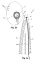
- Fig. 4 shows a fourth embodiment of a blade 201 according to the invention.
- the blade 201 according to this embodiment has a tip 205 formed as a substantially solid body of e.g. polyurethane, PVC or fibre-reinforced polymer as in the embodiment shown in Fig. 3 .
- the rest of the blade 201 is made of a shell body having a laminate shell 206.
- the lightning protection system of the blade 201 includes a lightning down conductor 202 extending substantially in the entire longitudinal direction of the blade 201 from the root end at the rotor hub and to the tip end.
- the lightning down conductor 202 is guided out of the cavity of the blade 201 and into a hole created in the tip 205 and fitting the shape of the lightning down conductor 202.
- the lightning down conductor 202 is connected to a lightning receptor 203 having a rounded shape and positioned at the apex of the tip 205.
- the lightning receptor 203 is adapted so that there is a substantially smooth transition between the tip 205 and the receptor 203 and so that it has the desired aerodynamic properties of the tip 201.
- the receptor 203 according to this embodiment is a part of the tip of the blade 201.
- the lightning down conductor 202 and the receptor 203 are connected by means of a clamped connection or a threaded connection 211. Moreover, the lightning down conductor is anchored to the tip 205 by means of two plastic rods 210 with outer thread and two threaded holes in the receptor 203.
- the connection area between the lightning down conductor 202 and the receptor 203 is electrically insulated by means of a further insulation in the form of e.g. a shrink material or silicone.
- the solid tip 205 may be sufficient to provide the desired electrical insulation.
- the present applicant has conducted a number of tests to examine lightning protection systems for blades in such worst-case scenarios.
- the so-called high voltage switching and lightning impulse simulations were conducted by suspending a blade in a horizontal position above a laboratory floor or surface which during the test simulates an equipotential surface, which prior to a lightning strike occurs above the blade, while being near the horizontal position.
- a potential difference was built up between the laboratory surface and the lightning protection system of the blade to provoke a flashover between the lightning protection system of the blade and the laboratory floor.
- the tests were carried out with both positive and negative polarity, where flashovers with positive polarity were carried out at 1050 kV, while flashovers with negative polarity were carried out at 1400 kV.
- a lightning down conductor in the form of a cable having a copper core and an insulation made of high density polyethylene (HDPE) was particularly effective in preventing lightning striking through the surface of the blade. After 22 simulated lightning strikes, 12 positive ones and 10 negative ones, the blade showed no visible damage or other negative effects. During all simulated lightning strikes only streamer formation at the receptor of the blade was observed.
- HDPE high density polyethylene
- the examined cable is constructed of a 50 mm 2 core 21 made of copper wires and an approx. 4,5 mm thick insulation sheathing 22 made of HDPE. Between the core 21 and the insulation 22, there is provided a semiconductive material 23 having the object to minimize electrical field concentrations at the individual copper wires.
- the semiconductive material 23 is not absolutely necessary to achieve the desired effect for the lightning protection system. It was found to be sufficient to use a comparatively thin HDPE insulation. This is advantageous, since the cable does not result in an unnecessarily large increase in the blade weight. Moreover, such a cable is very inexpensive.
- the novel lightning protection system does not only effectively prevent lightning strikes through the surface of the blade, but also provides a simpler construction and is less expensive to manufacture than traditional lightning protection systems with or without multireceptors.
Priority Applications (8)
| Application Number | Priority Date | Filing Date | Title |
|---|---|---|---|
| EP09154511A EP2226497A1 (de) | 2009-03-06 | 2009-03-06 | Windturbinenschaufel mit Blitzschutzsystem |
| PL10707045T PL2404056T3 (pl) | 2009-03-06 | 2010-03-08 | Łopata turbiny wiatrowej z systemem ochrony odgromowej i sposób modernizowania |
| DK10707045.0T DK2404056T3 (en) | 2009-03-06 | 2010-03-08 | Wind turbine blade with lightning protection system and retrofitting method |
| CN201080010748.XA CN102365454B (zh) | 2009-03-06 | 2010-03-08 | 具有闪电保护系统的风力涡轮机叶片 |
| ES10707045.0T ES2643622T3 (es) | 2009-03-06 | 2010-03-08 | Pala de turbina eólica con sistema de protección contra rayos y método de actualización |
| PCT/EP2010/052904 WO2010100283A1 (en) | 2009-03-06 | 2010-03-08 | Wind turbine blade with a lightning protection system |
| EP10707045.0A EP2404056B1 (de) | 2009-03-06 | 2010-03-08 | Windturbinenschaufel mit blitzschutzsystem und retrofit-verfahren |
| US13/254,495 US8888454B2 (en) | 2009-03-06 | 2010-03-08 | Wind turbine blade with a lightning protection system |
Applications Claiming Priority (1)
| Application Number | Priority Date | Filing Date | Title |
|---|---|---|---|
| EP09154511A EP2226497A1 (de) | 2009-03-06 | 2009-03-06 | Windturbinenschaufel mit Blitzschutzsystem |
Publications (1)
| Publication Number | Publication Date |
|---|---|
| EP2226497A1 true EP2226497A1 (de) | 2010-09-08 |
Family
ID=40740096
Family Applications (2)
| Application Number | Title | Priority Date | Filing Date |
|---|---|---|---|
| EP09154511A Withdrawn EP2226497A1 (de) | 2009-03-06 | 2009-03-06 | Windturbinenschaufel mit Blitzschutzsystem |
| EP10707045.0A Active EP2404056B1 (de) | 2009-03-06 | 2010-03-08 | Windturbinenschaufel mit blitzschutzsystem und retrofit-verfahren |
Family Applications After (1)
| Application Number | Title | Priority Date | Filing Date |
|---|---|---|---|
| EP10707045.0A Active EP2404056B1 (de) | 2009-03-06 | 2010-03-08 | Windturbinenschaufel mit blitzschutzsystem und retrofit-verfahren |
Country Status (7)
| Country | Link |
|---|---|
| US (1) | US8888454B2 (de) |
| EP (2) | EP2226497A1 (de) |
| CN (1) | CN102365454B (de) |
| DK (1) | DK2404056T3 (de) |
| ES (1) | ES2643622T3 (de) |
| PL (1) | PL2404056T3 (de) |
| WO (1) | WO2010100283A1 (de) |
Cited By (13)
| Publication number | Priority date | Publication date | Assignee | Title |
|---|---|---|---|---|
| WO2013007267A1 (en) * | 2011-07-14 | 2013-01-17 | Vestas Wind Systems A/S | A wind turbine blade |
| WO2014075976A1 (de) * | 2012-11-15 | 2014-05-22 | Wobben Properties Gmbh | Rotorblattspitze |
| WO2015055213A1 (en) * | 2013-10-17 | 2015-04-23 | Vestas Wind Systems A/S | Improvements relating to lightning protection systems for wind turbine blades |
| WO2015131900A1 (en) * | 2014-03-06 | 2015-09-11 | Global Lightning Protection Services A/S | Lightning measuring system for a wind turbine |
| WO2016074677A1 (en) * | 2014-11-14 | 2016-05-19 | Global Lightning Protection Services A/S | A fully insulated tip unit for a lightning protection system for a wind turbine blade and a wind turbine blade comprising the same |
| WO2018095649A1 (en) * | 2016-11-28 | 2018-05-31 | Siemens Aktiengesellschaft | Blade for a wind turbine and connection arrangement |
| WO2018137806A1 (en) * | 2017-01-24 | 2018-08-02 | Siemens Wind Power A/S | Lightning protection arrangement |
| CN108425811A (zh) * | 2018-06-19 | 2018-08-21 | 华润电力风能(汕头)有限公司 | 一种风机叶片防雷系统 |
| US10465662B2 (en) | 2013-10-17 | 2019-11-05 | Vestas Wind Systems A/S | Improvements relating to lightning protection systems for wind turbine blades |
| EP3628863A1 (de) * | 2018-09-26 | 2020-04-01 | Siemens Gamesa Renewable Energy A/S | Blitzschutz für einen rotorblattaufsatz |
| US10669996B2 (en) | 2013-10-17 | 2020-06-02 | Vestas Wind Systems A/S | Lightning protection systems for wind turbine blades |
| US11619205B2 (en) | 2017-04-26 | 2023-04-04 | Vestas Wind Systems A/S | Wind turbine blade and wind turbine power generating apparatus |
| US11644011B2 (en) | 2018-07-09 | 2023-05-09 | Vestas Wind Systems A/S | Relating to wind turbine blades |
Families Citing this family (33)
| Publication number | Priority date | Publication date | Assignee | Title |
|---|---|---|---|---|
| DE102009046293B4 (de) * | 2009-11-02 | 2013-03-28 | Repower Systems Ag | Rotorblatt mit Entwässerungsbohrung |
| KR20130084612A (ko) * | 2011-12-09 | 2013-07-25 | 미츠비시 쥬고교 가부시키가이샤 | 풍차 날개 |
| DK2855929T3 (en) * | 2012-06-04 | 2018-07-16 | Lm Wind Power Int Tech Ii Aps | A lightning bypass system for a wind turbine blade |
| DE102013107296B4 (de) * | 2013-07-10 | 2015-03-19 | Senvion Se | Rotorblatt mit Blitzableiter |
| US9702255B2 (en) | 2013-11-26 | 2017-07-11 | Textron Innovations, Inc. | Propeller with lightening strike protection |
| US9205920B2 (en) | 2013-12-30 | 2015-12-08 | Google Inc. | Wiring harness for an aerial vehicle |
| US20150300324A1 (en) * | 2014-04-18 | 2015-10-22 | Ashish Bhimrao Kharkar | Electromagnetic shielding of a strain gauge in a wind power installation |
| JP5941174B1 (ja) * | 2015-02-03 | 2016-06-29 | 株式会社日立製作所 | 風力発電装置 |
| WO2016165713A1 (en) * | 2015-04-17 | 2016-10-20 | Global Lightning Protection Services A/S | Side receptor for lightning protection system |
| ES2667501T3 (es) * | 2015-08-10 | 2018-05-11 | Nordex Energy Gmbh | Pala de rotor de instalación de energía eólica con un descargador de chispa |
| CN105604812B (zh) * | 2016-02-26 | 2018-10-12 | 北京金风科创风电设备有限公司 | 接闪器、叶片防雷系统及风力发电机组的叶片 |
| USD803163S1 (en) | 2016-05-13 | 2017-11-21 | Erico International Corporation | Tip receptor mount for lightning protection systems |
| US10344743B2 (en) | 2016-05-13 | 2019-07-09 | Erico International Corporation | Lightning protection system and method for wind turbine blades |
| EP3246562B1 (de) | 2016-05-18 | 2019-02-13 | Nordex Energy GmbH | Blitzrezeptor für ein windenergieanlagenrotorblatt |
| EP3255276B1 (de) * | 2016-06-09 | 2019-02-27 | Siemens Aktiengesellschaft | Blitzschutzsystem einer windkraft-anlage |
| US10443579B2 (en) * | 2016-11-15 | 2019-10-15 | General Electric Company | Tip extensions for wind turbine rotor blades and methods of installing same |
| US10830214B2 (en) * | 2017-03-22 | 2020-11-10 | General Electric Company | Method for securing a lightning receptor cable within a segmented rotor blade |
| DE102017007371A1 (de) * | 2017-08-07 | 2019-02-07 | Senvion Gmbh | Rotorblatt einer Windenergieanlage und Verfahren zum Nachrüsten einer Blitzschutzeinrichtung eines Rotorblatts |
| EP3456961B1 (de) * | 2017-09-14 | 2020-07-01 | Siemens Gamesa Renewable Energy A/S | Windturbinenschaufel mit deckplatte zur maskierung von heissluftabgas für die enteisung und/oder eisschutz |
| CN107420271B (zh) * | 2017-09-15 | 2019-05-03 | 宁夏中科天际防雷股份有限公司 | 一种电流传输设备雷电防护装置 |
| CN108223306B (zh) * | 2017-12-29 | 2020-06-26 | 中国电力科学研究院有限公司 | 一种外覆于风电机组叶片表面的防雷接闪装置 |
| CN108223305B (zh) * | 2017-12-29 | 2021-03-26 | 中国电力科学研究院有限公司 | 风电机组叶片用电极接闪装置 |
| CN108223260A (zh) * | 2017-12-29 | 2018-06-29 | 华润电力风能(汕头潮南)有限公司 | 一种风机叶片改造方法及风机叶片 |
| JP6655660B2 (ja) * | 2018-06-15 | 2020-02-26 | 三菱重工業株式会社 | 風車翼保護構造及びその形成方法 |
| JP6657314B2 (ja) * | 2018-06-15 | 2020-03-04 | 三菱重工業株式会社 | 風車翼保護構造及びその形成方法 |
| EP3736443A1 (de) * | 2019-05-09 | 2020-11-11 | Siemens Gamesa Renewable Energy A/S | Schaufel für eine windturbine sowie windturbine |
| CN110792564B (zh) * | 2019-11-06 | 2020-12-15 | 华北电力大学 | 一种风机叶片引下线故障检测与定位方法及装置 |
| CN111237124B (zh) * | 2020-02-19 | 2021-11-05 | 上海电气风电集团股份有限公司 | 一种集合风电叶片前缘防护和雷击防护的系统 |
| US11441545B2 (en) * | 2020-02-25 | 2022-09-13 | General Electric Company | Tungsten-based erosion-resistant leading edge protection cap for rotor blades |
| EP3875751A1 (de) * | 2020-03-02 | 2021-09-08 | Nordex Energy SE & Co. KG | Rotorblatt für eine windenergieanlage und rotorblattspitze |
| WO2021178542A1 (en) * | 2020-03-03 | 2021-09-10 | Wichita State University | Lightning protection covering |
| CN113958467B (zh) * | 2021-09-13 | 2023-04-18 | 中国船舶重工集团海装风电股份有限公司 | 一种风电机组叶片的防雷接闪组合装置 |
| JP7355142B1 (ja) | 2022-03-17 | 2023-10-03 | 株式会社明電舎 | 風力発電装置のブレード用レセプタ |
Citations (7)
| Publication number | Priority date | Publication date | Assignee | Title |
|---|---|---|---|---|
| WO1996007825A1 (en) | 1994-09-07 | 1996-03-14 | Bonus Energy A/S | Lightning arrester for windmill blades |
| WO2000014405A1 (en) * | 1998-09-09 | 2000-03-16 | Lm Glasfiber A/S | Lightning protection for wind turbine blade |
| EP1011182A1 (de) * | 1998-12-14 | 2000-06-21 | Minnesota Mining And Manufacturing Company | Blitzschutzvorrichtung für längliche Körper |
| WO2001077527A1 (en) * | 2000-04-10 | 2001-10-18 | Jomitek Aps | Lightning protection system for, e.g., a wind turbine, wind turbine blade having a lightning protection system, method of creating a lightning protection system and use thereof |
| WO2007062659A1 (en) * | 2005-12-02 | 2007-06-07 | Lm Glasfiber A/S | Lightning protection system for a wind turbine blade |
| WO2008006377A1 (en) * | 2006-07-14 | 2008-01-17 | Vestas Wind Systems A/S | Wind turbine comprising enclosure structure formed as a faraday cage |
| US20080095624A1 (en) * | 2006-10-19 | 2008-04-24 | Bastian Lewke | Lightning protection of wind turbines |
Family Cites Families (7)
| Publication number | Priority date | Publication date | Assignee | Title |
|---|---|---|---|---|
| DK173607B1 (da) * | 1999-06-21 | 2001-04-30 | Lm Glasfiber As | Vindmøllevinge med system til afisning af lynbeskyttelse |
| JP4580169B2 (ja) * | 2004-02-05 | 2010-11-10 | 富士重工業株式会社 | 風車用分割型ブレード及び風車の耐雷装置 |
| US7751198B2 (en) | 2006-09-11 | 2010-07-06 | Apple Inc. | Multi-connector assembly |
| JP5072678B2 (ja) * | 2008-03-24 | 2012-11-14 | 三菱重工業株式会社 | 落雷シミュレーション装置及びその方法並びにプログラム |
| US8137074B2 (en) * | 2008-08-21 | 2012-03-20 | General Electric Company | Wind turbine lightning protection system |
| AU2010336835A1 (en) * | 2009-12-24 | 2012-01-12 | Mitsubishi Heavy Industries, Ltd. | Wind wheel blade and wind-driven electricity generation device with same |
| US7988415B2 (en) * | 2010-08-31 | 2011-08-02 | General Electric Company | Lightning protection for wind turbines |
-
2009
- 2009-03-06 EP EP09154511A patent/EP2226497A1/de not_active Withdrawn
-
2010
- 2010-03-08 CN CN201080010748.XA patent/CN102365454B/zh active Active
- 2010-03-08 PL PL10707045T patent/PL2404056T3/pl unknown
- 2010-03-08 US US13/254,495 patent/US8888454B2/en active Active
- 2010-03-08 EP EP10707045.0A patent/EP2404056B1/de active Active
- 2010-03-08 ES ES10707045.0T patent/ES2643622T3/es active Active
- 2010-03-08 DK DK10707045.0T patent/DK2404056T3/en active
- 2010-03-08 WO PCT/EP2010/052904 patent/WO2010100283A1/en active Application Filing
Patent Citations (7)
| Publication number | Priority date | Publication date | Assignee | Title |
|---|---|---|---|---|
| WO1996007825A1 (en) | 1994-09-07 | 1996-03-14 | Bonus Energy A/S | Lightning arrester for windmill blades |
| WO2000014405A1 (en) * | 1998-09-09 | 2000-03-16 | Lm Glasfiber A/S | Lightning protection for wind turbine blade |
| EP1011182A1 (de) * | 1998-12-14 | 2000-06-21 | Minnesota Mining And Manufacturing Company | Blitzschutzvorrichtung für längliche Körper |
| WO2001077527A1 (en) * | 2000-04-10 | 2001-10-18 | Jomitek Aps | Lightning protection system for, e.g., a wind turbine, wind turbine blade having a lightning protection system, method of creating a lightning protection system and use thereof |
| WO2007062659A1 (en) * | 2005-12-02 | 2007-06-07 | Lm Glasfiber A/S | Lightning protection system for a wind turbine blade |
| WO2008006377A1 (en) * | 2006-07-14 | 2008-01-17 | Vestas Wind Systems A/S | Wind turbine comprising enclosure structure formed as a faraday cage |
| US20080095624A1 (en) * | 2006-10-19 | 2008-04-24 | Bastian Lewke | Lightning protection of wind turbines |
Cited By (24)
| Publication number | Priority date | Publication date | Assignee | Title |
|---|---|---|---|---|
| WO2013007267A1 (en) * | 2011-07-14 | 2013-01-17 | Vestas Wind Systems A/S | A wind turbine blade |
| RU2608453C2 (ru) * | 2012-11-15 | 2017-01-18 | Воббен Пропертиз Гмбх | Законцовка лопасти ротора |
| WO2014075976A1 (de) * | 2012-11-15 | 2014-05-22 | Wobben Properties Gmbh | Rotorblattspitze |
| EP3462019A1 (de) * | 2013-10-17 | 2019-04-03 | Vestas Wind Systems A/S | Verbesserungen an blitzschutzsystemen für windturbinenschaufeln |
| WO2015055213A1 (en) * | 2013-10-17 | 2015-04-23 | Vestas Wind Systems A/S | Improvements relating to lightning protection systems for wind turbine blades |
| US11225949B2 (en) | 2013-10-17 | 2022-01-18 | Vestas Wind Systems A/S | Lightning protection systems for wind turbine blades |
| US10883479B2 (en) | 2013-10-17 | 2021-01-05 | Vestas Wind Systems A/S | Relating to lightning protection systems for wind turbine blades |
| US10465662B2 (en) | 2013-10-17 | 2019-11-05 | Vestas Wind Systems A/S | Improvements relating to lightning protection systems for wind turbine blades |
| US10669996B2 (en) | 2013-10-17 | 2020-06-02 | Vestas Wind Systems A/S | Lightning protection systems for wind turbine blades |
| WO2015131900A1 (en) * | 2014-03-06 | 2015-09-11 | Global Lightning Protection Services A/S | Lightning measuring system for a wind turbine |
| WO2016074677A1 (en) * | 2014-11-14 | 2016-05-19 | Global Lightning Protection Services A/S | A fully insulated tip unit for a lightning protection system for a wind turbine blade and a wind turbine blade comprising the same |
| EP3218596B1 (de) | 2014-11-14 | 2022-10-26 | Polytech A/S | Vollständig isolierte spitze für ein blitzschutzsystem für eine windturbinenschaufel und windturbinenschaufel damit |
| US10612526B2 (en) | 2014-11-14 | 2020-04-07 | Polytech A/S | Fully insulated tip unit for a lightning protection system for a wind turbine blade and a wind turbine blade comprising the same |
| WO2018095649A1 (en) * | 2016-11-28 | 2018-05-31 | Siemens Aktiengesellschaft | Blade for a wind turbine and connection arrangement |
| CN110234871A (zh) * | 2017-01-24 | 2019-09-13 | 西门子歌美飒可再生能源公司 | 防雷装置 |
| US11118571B2 (en) | 2017-01-24 | 2021-09-14 | Siemens Gamesa Renewable Energy A/S | Lightning protection arrangement |
| WO2018137806A1 (en) * | 2017-01-24 | 2018-08-02 | Siemens Wind Power A/S | Lightning protection arrangement |
| US11619205B2 (en) | 2017-04-26 | 2023-04-04 | Vestas Wind Systems A/S | Wind turbine blade and wind turbine power generating apparatus |
| CN108425811A (zh) * | 2018-06-19 | 2018-08-21 | 华润电力风能(汕头)有限公司 | 一种风机叶片防雷系统 |
| CN108425811B (zh) * | 2018-06-19 | 2024-04-12 | 华润电力风能(汕头)有限公司 | 一种风机叶片防雷系统 |
| US11644011B2 (en) | 2018-07-09 | 2023-05-09 | Vestas Wind Systems A/S | Relating to wind turbine blades |
| CN110953127A (zh) * | 2018-09-26 | 2020-04-03 | 西门子歌美飒可再生能源公司 | 用于转子叶片附加组件的雷电保护 |
| EP3628863A1 (de) * | 2018-09-26 | 2020-04-01 | Siemens Gamesa Renewable Energy A/S | Blitzschutz für einen rotorblattaufsatz |
| US11913433B2 (en) | 2018-09-26 | 2024-02-27 | Siemens Gamesa Renewable Energy A/S | Lightning protection for a rotor blade add-on |
Also Published As
| Publication number | Publication date |
|---|---|
| DK2404056T3 (en) | 2017-10-30 |
| CN102365454A (zh) | 2012-02-29 |
| ES2643622T3 (es) | 2017-11-23 |
| WO2010100283A1 (en) | 2010-09-10 |
| CN102365454B (zh) | 2014-03-05 |
| US20120003094A1 (en) | 2012-01-05 |
| EP2404056B1 (de) | 2017-07-12 |
| US8888454B2 (en) | 2014-11-18 |
| PL2404056T3 (pl) | 2018-01-31 |
| EP2404056A1 (de) | 2012-01-11 |
Similar Documents
| Publication | Publication Date | Title |
|---|---|---|
| EP2404056B1 (de) | Windturbinenschaufel mit blitzschutzsystem und retrofit-verfahren | |
| EP1957791B1 (de) | Blitzschutzsystem für windturbinenschaufel | |
| US9041410B2 (en) | Wind turbine blade with lightning protection system | |
| EP2944809B1 (de) | Verfahren zur herstellung einer windturbinenschaufel | |
| CN101233317B (zh) | 风力涡轮机的雷电保护系统 | |
| WO2013007267A1 (en) | A wind turbine blade | |
| EP3510282A1 (de) | Blitzableiter für eine rotorschaufel einer windturbine | |
| CA2772211A1 (en) | A partial pitch wind turbine blade with lightning protection | |
| US8215911B2 (en) | Wind power plant with lightning protection arrangement | |
| EP3870837A1 (de) | Blitzschutz für eine windturbinenschaufel |
Legal Events
| Date | Code | Title | Description |
|---|---|---|---|
| PUAI | Public reference made under article 153(3) epc to a published international application that has entered the european phase |
Free format text: ORIGINAL CODE: 0009012 |
|
| AK | Designated contracting states |
Kind code of ref document: A1 Designated state(s): AT BE BG CH CY CZ DE DK EE ES FI FR GB GR HR HU IE IS IT LI LT LU LV MC MK MT NL NO PL PT RO SE SI SK TR |
|
| AX | Request for extension of the european patent |
Extension state: AL BA RS |
|
| AKX | Designation fees paid |
Designated state(s): AT BE BG CH CY CZ DE DK EE ES FI FR GB GR HR HU IE IS IT LI LT LU LV MC MK MT NL NO PL PT RO SE SI SK TR |
|
| STAA | Information on the status of an ep patent application or granted ep patent |
Free format text: STATUS: THE APPLICATION IS DEEMED TO BE WITHDRAWN |
|
| 18D | Application deemed to be withdrawn |
Effective date: 20110309 |
|
| P01 | Opt-out of the competence of the unified patent court (upc) registered |
Effective date: 20230522 |