EP3130764A1 - Steam valve - Google Patents
Steam valve Download PDFInfo
- Publication number
- EP3130764A1 EP3130764A1 EP15776819.3A EP15776819A EP3130764A1 EP 3130764 A1 EP3130764 A1 EP 3130764A1 EP 15776819 A EP15776819 A EP 15776819A EP 3130764 A1 EP3130764 A1 EP 3130764A1
- Authority
- EP
- European Patent Office
- Prior art keywords
- steam
- valve
- valve element
- discharge hole
- guide tube
- Prior art date
- Legal status (The legal status is an assumption and is not a legal conclusion. Google has not performed a legal analysis and makes no representation as to the accuracy of the status listed.)
- Granted
Links
Images








Classifications
-
- F—MECHANICAL ENGINEERING; LIGHTING; HEATING; WEAPONS; BLASTING
- F01—MACHINES OR ENGINES IN GENERAL; ENGINE PLANTS IN GENERAL; STEAM ENGINES
- F01D—NON-POSITIVE DISPLACEMENT MACHINES OR ENGINES, e.g. STEAM TURBINES
- F01D17/00—Regulating or controlling by varying flow
- F01D17/10—Final actuators
- F01D17/12—Final actuators arranged in stator parts
- F01D17/14—Final actuators arranged in stator parts varying effective cross-sectional area of nozzles or guide conduits
- F01D17/141—Final actuators arranged in stator parts varying effective cross-sectional area of nozzles or guide conduits by means of shiftable members or valves obturating part of the flow path
- F01D17/145—Final actuators arranged in stator parts varying effective cross-sectional area of nozzles or guide conduits by means of shiftable members or valves obturating part of the flow path by means of valves, e.g. for steam turbines
-
- F—MECHANICAL ENGINEERING; LIGHTING; HEATING; WEAPONS; BLASTING
- F01—MACHINES OR ENGINES IN GENERAL; ENGINE PLANTS IN GENERAL; STEAM ENGINES
- F01D—NON-POSITIVE DISPLACEMENT MACHINES OR ENGINES, e.g. STEAM TURBINES
- F01D17/00—Regulating or controlling by varying flow
- F01D17/10—Final actuators
-
- F—MECHANICAL ENGINEERING; LIGHTING; HEATING; WEAPONS; BLASTING
- F01—MACHINES OR ENGINES IN GENERAL; ENGINE PLANTS IN GENERAL; STEAM ENGINES
- F01D—NON-POSITIVE DISPLACEMENT MACHINES OR ENGINES, e.g. STEAM TURBINES
- F01D25/00—Component parts, details, or accessories, not provided for in, or of interest apart from, other groups
-
- F—MECHANICAL ENGINEERING; LIGHTING; HEATING; WEAPONS; BLASTING
- F16—ENGINEERING ELEMENTS AND UNITS; GENERAL MEASURES FOR PRODUCING AND MAINTAINING EFFECTIVE FUNCTIONING OF MACHINES OR INSTALLATIONS; THERMAL INSULATION IN GENERAL
- F16K—VALVES; TAPS; COCKS; ACTUATING-FLOATS; DEVICES FOR VENTING OR AERATING
- F16K1/00—Lift valves or globe valves, i.e. cut-off apparatus with closure members having at least a component of their opening and closing motion perpendicular to the closing faces
- F16K1/12—Lift valves or globe valves, i.e. cut-off apparatus with closure members having at least a component of their opening and closing motion perpendicular to the closing faces with streamlined valve member around which the fluid flows when the valve is opened
-
- F—MECHANICAL ENGINEERING; LIGHTING; HEATING; WEAPONS; BLASTING
- F16—ENGINEERING ELEMENTS AND UNITS; GENERAL MEASURES FOR PRODUCING AND MAINTAINING EFFECTIVE FUNCTIONING OF MACHINES OR INSTALLATIONS; THERMAL INSULATION IN GENERAL
- F16K—VALVES; TAPS; COCKS; ACTUATING-FLOATS; DEVICES FOR VENTING OR AERATING
- F16K1/00—Lift valves or globe valves, i.e. cut-off apparatus with closure members having at least a component of their opening and closing motion perpendicular to the closing faces
- F16K1/30—Lift valves or globe valves, i.e. cut-off apparatus with closure members having at least a component of their opening and closing motion perpendicular to the closing faces specially adapted for pressure containers
- F16K1/307—Additional means used in combination with the main valve
-
- F—MECHANICAL ENGINEERING; LIGHTING; HEATING; WEAPONS; BLASTING
- F16—ENGINEERING ELEMENTS AND UNITS; GENERAL MEASURES FOR PRODUCING AND MAINTAINING EFFECTIVE FUNCTIONING OF MACHINES OR INSTALLATIONS; THERMAL INSULATION IN GENERAL
- F16K—VALVES; TAPS; COCKS; ACTUATING-FLOATS; DEVICES FOR VENTING OR AERATING
- F16K1/00—Lift valves or globe valves, i.e. cut-off apparatus with closure members having at least a component of their opening and closing motion perpendicular to the closing faces
- F16K1/32—Details
- F16K1/34—Cutting-off parts, e.g. valve members, seats
- F16K1/44—Details of seats or valve members of double-seat valves
- F16K1/443—Details of seats or valve members of double-seat valves the seats being in series
-
- F—MECHANICAL ENGINEERING; LIGHTING; HEATING; WEAPONS; BLASTING
- F16—ENGINEERING ELEMENTS AND UNITS; GENERAL MEASURES FOR PRODUCING AND MAINTAINING EFFECTIVE FUNCTIONING OF MACHINES OR INSTALLATIONS; THERMAL INSULATION IN GENERAL
- F16K—VALVES; TAPS; COCKS; ACTUATING-FLOATS; DEVICES FOR VENTING OR AERATING
- F16K1/00—Lift valves or globe valves, i.e. cut-off apparatus with closure members having at least a component of their opening and closing motion perpendicular to the closing faces
- F16K1/32—Details
- F16K1/34—Cutting-off parts, e.g. valve members, seats
- F16K1/44—Details of seats or valve members of double-seat valves
- F16K1/443—Details of seats or valve members of double-seat valves the seats being in series
- F16K1/446—Details of seats or valve members of double-seat valves the seats being in series with additional cleaning or venting means between the two seats
-
- F—MECHANICAL ENGINEERING; LIGHTING; HEATING; WEAPONS; BLASTING
- F16—ENGINEERING ELEMENTS AND UNITS; GENERAL MEASURES FOR PRODUCING AND MAINTAINING EFFECTIVE FUNCTIONING OF MACHINES OR INSTALLATIONS; THERMAL INSULATION IN GENERAL
- F16K—VALVES; TAPS; COCKS; ACTUATING-FLOATS; DEVICES FOR VENTING OR AERATING
- F16K51/00—Other details not peculiar to particular types of valves or cut-off apparatus
-
- F—MECHANICAL ENGINEERING; LIGHTING; HEATING; WEAPONS; BLASTING
- F05—INDEXING SCHEMES RELATING TO ENGINES OR PUMPS IN VARIOUS SUBCLASSES OF CLASSES F01-F04
- F05D—INDEXING SCHEME FOR ASPECTS RELATING TO NON-POSITIVE-DISPLACEMENT MACHINES OR ENGINES, GAS-TURBINES OR JET-PROPULSION PLANTS
- F05D2220/00—Application
- F05D2220/30—Application in turbines
- F05D2220/31—Application in turbines in steam turbines
Definitions
- the operation under a narrowed valve opening degree of the steam control valve 320 that is, under a low flow rate of the steam passing through the steam valve 300, sometimes causes an abnormal temperature increase of the drain pipe 370 more on the steam valve 300 side than the shutoff valve 380.
- a possible reason for this to occur may be a thermoacoustic effect caused by the pressure fluctuation in the drain pipe 370. Such an abnormal temperature increase may cause breakage of the drain pipe.
- the steam valve further includes: a casing housing the first valve element, the second valve element, the valve seat, and the guide tube; a drain discharge hole formed in a sidewall of the casing at a bottom side; a drain pipe provided with a shutoff valve and communicating with the drain discharge hole; and a flow direction changing part which changes a direction in which the steam having passed between the first valve element and the valve seat and flowing along the guide tube, flows toward the drain discharge hole.
- the structure of the steam valve 11 of the second embodiment is the same as the structure of the steam valve 10 of the first embodiment except the structure of the flow direction changing part 80. Therefore, the flow direction changing part 80 is mainly described here.
- the tubular body 90 has a cylindrical shape, for instance. As illustrated in Fig. 6 , a height H of the tubular body 90 is smaller than the height I of the flange portion 43a of the guide tube 43.
- the tubular body 90 is fixed to the bottom surface of the casing 20 by welding or the like, for instance. Further, the example where the cross section of the communication hole 93 is rectangular is given here, but this cross section may be circular.
- the flow direction changing part 80 includes groove portions 100 formed in the side surface of the guide tube 43 on the drain discharge hole 23 side and arranged in the axial direction in a plurality of tiers.
- these groove portions 100 are each formed along a half circumference of the side surface of the guide tube 43 which is the cylinder, that is, along 1/2 of the circumference.
- Fig. 12 is a view illustrating a vertical cross section of a steam valve 13 of a fourth embodiment.
- the structure of the steam valve 13 of the fourth embodiment is the same as the structure of the steam valve 10 of the first embodiment except the structure of the flow direction changing part 80. Therefore, the flow direction changing part 80 is mainly described here.
- Fig. 13 is a view illustrating a vertical cross section of a steam valve 14 of a fifth embodiment.
- Fig. 14 is a view illustrating a C-C section in Fig. 13 .
- the structure of the steam valve 14 of the fifth embodiment is the same as the structure of the steam valve 10 of the first embodiment except the structure of the flow direction changing part 80. Therefore, the flow direction changing part 80 is mainly described here.
Landscapes
- Engineering & Computer Science (AREA)
- General Engineering & Computer Science (AREA)
- Mechanical Engineering (AREA)
- Physics & Mathematics (AREA)
- Fluid Mechanics (AREA)
- Lift Valve (AREA)
- Control Of Turbines (AREA)
- Details Of Valves (AREA)
Abstract
Description
- Embodiments described herein relate generally to a steam valve.
- A steam turbine pipe system includes a main steam pipe which leads steam generated in a boiler to a steam turbine. In this main steam pipe, a steam valve for regulating a flow rate of the steam and shutting off the steam is provided.
-
Fig. 18 is a view illustrating a vertical cross section of aconventional steam valve 300. Theconventional steam valve 300 provided in a main steam pipe is what is called a combined steam valve in which a steam control valve and a main stop valve are combined in onecasing 310. - As illustrated in
Fig. 18 , thesteam valve 300 includes: asteam control valve 320 movable in an up and down direction when driven from above; and amain stop valve 330 provided under thesteam control valve 320 coaxially with thesteam control valve 320 and movable in the up and down direction when driven from under. Thesteam valve 300 further includes acylindrical strainer 340 disposed so as to surround thesteam control valve 320 and themain stop valve 330. Thestrainer 340 prevents a foreign object in the steam led through asteam inlet 311 from flowing downstream. - The
steam control valve 320 includes avalve rod 321 and avalve element 323. Thevalve rod 321 penetrates through anupper cover 350 and is movable in the up and down direction when driven from above. Thevalve element 323 is provided annularly on a lower end side of thevalve rod 321 and has a dentedportion 322 in its lower surface. - The
main stop valve 330 includes avalve rod 331, avalve element 332, and aguide tube 333. Thevalve rod 331 penetrates through a bottom portion of thecasing 310 and is movable in the up and down direction when driven from under. Thevalve element 332 is provided on an upper end side of thevalve rod 331 and protrudes radially outward from thevalve rod 331 all over the circumferential direction. Thevalve element 332 is housed in the dentedportion 322 of thevalve element 323 of thesteam control valve 320. Theguide tube 333 is a cylinder fixed to the bottom portion of thecasing 310 and having thevalve rod 331 penetrating therethrough at its center. - Under the
valve element 323 of thesteam control valve 320 and thevalve element 332 of themain stop valve 330, avalve seat 360 which comes into contact with these valve elements is provided. When thevalve element 323 of thesteam control valve 320 and thevalve element 332 of themain stop valve 330 are pressed while in contact with thevalve seat 360, it is possible to shut off the flow of the steam. - At the bottom side of the
casing 310, adrain discharge hole 312 for discharging a drain generated during warming for putting the steam turbine into operation is provided. As illustrated inFig. 18 , due to arrangement and structural reasons, thedrain discharge hole 312 is formed in a sidewall of thecasing 310 at the bottom side so as to extend laterally (in the horizontal direction inFig. 18 ). Further, adrain pipe 370 is provided on thedrain discharge hole 312 to lead the drain to the outside. Ashutoff valve 380 is provided in thedrain pipe 370. When theshutoff valve 380 is opened, the drain generated during the warming is led to a condenser. Then, theshutoff valve 380 is closed after the warming. That is, during the normal operation of the steam turbine, thedrain pipe 370 constitutes a pipe part whose one end communicates with the inside of thesteam valve 300 and whose other end is closed. - The
steam valve 300 having such a structure is supplied with the steam superheated by a superheater of the boiler disposed upstream of thesteam valve 300, through thesteam inlet 311. The steam led through thesteam inlet 311 passes through thestrainer 340 to pass between thevalve element 323 of thesteam control valve 320 and thevalve element 332 of themain stop valve 330, and thevalve seat 360. Flows of the steam having passed downward in a through portion provided at the center of thevalve seat 360 are bent along a steam passage downstream of thevalve seat 360. Then, the steam is discharged through asteam outlet 313 to be led to a high-pressure turbine. - At this time, the flow rate of the steam is adjusted by a valve opening degree of the
steam control valve 320. Specifically, when a required flow rate of the steam is small, the valve opening degree of thesteam control valve 320 is small, and when the required flow rate of the steam is large, the valve opening degree of thesteam control valve 320 is large. When the required flow rate of the steam is small, a gap between thevalve element 323 of thesteam control valve 320 and thevalve seat 360 is narrow and thus the flows of the steam are narrowed in this gap. Then, a flow velocity of the steam increases. - Here, as illustrated in
Fig. 18 , partial steam F of the steam having passed between thevalve element 323 of thesteam control valve 320 and thevalve seat 360 flows downward along a side surface of theguide tube 333. Then, the steam F flows along the shape of aflange portion 333a which is provided on theguide tube 333 at the bottom side of thecasing 310 to protrude outward all over the circumference direction. At this time, a component of velocity directed outward is added, and as illustrated inFig. 18 , the steam F flows outward. - Part of the steam F spreading in the circumferential direction flows toward an opening 312a of the
drain discharge hole 312. Thedrain pipe 370 is influenced by the steam F flowing toward thedrain discharge hole 312. Then, during the normal operation of the steam turbine, pressure fluctuation occurs in thedrain pipe 370 between the opening 312a of thedrain discharge hole 312 and theshutoff valve 380. - In steam turbines, temperature and pressure of steam have recently been increased for higher efficiency. Further, downsizing and the like of devices are also being considered in order to reduce a manufacturing cost. These increase the flow velocity of the steam flowing between the
valve element 323 of thesteam control valve 320 and thevalve seat 360 and the flow velocity of the steam flowing in the steam passage in thesteam valve 300. This tends to increase the pressure fluctuation occurring in thedrain pipe 370 due to the aforesaid steam F. - Non-patent Reference 1: Atsushi NARABE, Osamu SHINDO, "The Present and Trend of the Steam Valves for Steam Turbine", Turbomachinery VOL. 30 No. 7, Japan Industrial Publishing Co., Ltd., July 10, 2002, p.404-408,
Fig. 1 . - In the above-described
conventional steam valve 300, the operation under a narrowed valve opening degree of thesteam control valve 320, that is, under a low flow rate of the steam passing through thesteam valve 300, sometimes causes an abnormal temperature increase of thedrain pipe 370 more on thesteam valve 300 side than theshutoff valve 380. A possible reason for this to occur may be a thermoacoustic effect caused by the pressure fluctuation in thedrain pipe 370. Such an abnormal temperature increase may cause breakage of the drain pipe. - A problem to be solved by the present invention is to prevent an abnormal temperature increase of a drain pipe to provide a highly reliable steam valve.
- A steam valve of an embodiment includes: a first valve element which is provided to be movable in an up and down direction and adjusts a flow rate of steam; a second valve element which is provided under the first valve element coaxially with the first valve element to be movable in the up and down direction and shuts off a flow of the steam; a valve seat with which the first valve element and the second valve element come into and out of contact; and a guide tube slidably supporting a valve rod including the second valve element, and having a flange portion protruding outward all over the circumferential direction, at a bottom side in the steam valve.
- The steam valve further includes: a casing housing the first valve element, the second valve element, the valve seat, and the guide tube; a drain discharge hole formed in a sidewall of the casing at a bottom side; a drain pipe provided with a shutoff valve and communicating with the drain discharge hole; and a flow direction changing part which changes a direction in which the steam having passed between the first valve element and the valve seat and flowing along the guide tube, flows toward the drain discharge hole.
-
-
Fig. 1 is a system diagram illustrating an example of a power generation plant including a steam valve of a first embodiment. -
Fig. 2 is a perspective view of the steam valve of the first embodiment. -
Fig. 3 is a view illustrating a vertical cross section of the steam valve of the first embodiment. -
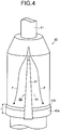
Fig. 4 is a perspective view of a flow direction changing part in the steam valve of the first embodiment. -
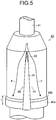
Fig. 5 is a perspective view of the flow direction changing part with another structure, in the steam valve of the first embodiment. -
Fig. 6 is a view illustrating a vertical cross section of a steam valve of a second embodiment. -
Fig. 7 is a perspective view of a flow direction changing part in the steam valve of the second embodiment. -
Fig. 8 is a view illustrating an A-A cross section inFig. 6 . -
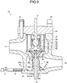
Fig. 9 is a vertical cross-sectional view of a steam valve of a third embodiment. -
Fig.10 is a perspective view of a flow direction changing part in the steam valve of the third embodiment. -
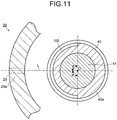
Fig. 11 is a view illustrating a B-B cross-section inFig. 9 . -
Fig. 12 is a view illustrating a vertical cross section of a steam valve of a fourth embodiment. -
Fig. 13 is a view illustrating a vertical cross section of a steam valve of a fifth embodiment. -
Fig. 14 is a view illustrating a C-C cross section inFig. 13 . -
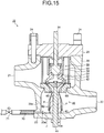
Fig. 15 is a view illustrating a vertical cross section of a steam valve of a sixth embodiment. -
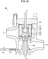
Fig. 16 is a view illustrating a vertical cross section of a steam valve of a seventh embodiment. -
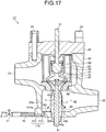
Fig. 17 is a view illustrating a vertical cross section of a steam valve of an eighth embodiment. -
Fig. 18 is a view illustrating a vertical cross section of a conventional steam valve. - Hereinafter, embodiments of the present invention are described with reference to the drawings.
-
Fig. 1 is a system diagram illustrating an example of apower generation plant 250 including asteam valve 10 of a first embodiment. - As illustrated in
Fig. 1 , in thepower generation plant 250, steam heated in asuperheater 252 of aboiler 251 is led to a high-pressure turbine 254 via amain steam pipe 253 and thesteam valve 10 provided in themain steam pipe 253. Note that thesteam valve 10, which will be describe later, is a combined steam valve having functions of a main stop valve and a steam control valve. - Here, for example, in a combined cycle system in which a gas turbine and a steam turbine are combined, the
boiler 251 functions as an exhaust heat recovery boiler. In this case, theboiler 251 functions by using exhaust gas from the gas turbine. In a case where the combined cycle system including the gas turbine is not constituted, theboiler 251 burns, for example, a fossil fuel to use its heat. - The steam having worked in the high-
pressure turbine 254 passes through a low-temperature reheat pipe 255 to be reheated in areheater 256 of theboiler 251 and is led to an intermediate-pressure turbine 259 via a high-temperature reheat pipe 257 and areheat steam valve 258 provided in the high-temperature reheat pipe 257. - The steam having worked in the intermediate-
pressure turbine 259 is led to low-pressure turbines 261 via acrossover pipe 260. The steam having worked in the low-pressure turbines 261 is returned to water in acondenser 262. Then, the water is supplied again to thesuperheater 252 of theboiler 251 by afeed pump 264 via a low-pressure feedwater heater 263 and a high-pressure feedwater heater 265. Further, for example, the high-pressure turbine 254, the intermediate-pressure turbine 259, and the low-pressure turbines 261 drive apower generator 266 to make it generate power. - Note that the structure of the
power generation plant 250 described here is an example, and its structure is not limited to this. - Next, the structure of the
steam valve 10 of the first embodiment is described. -
Fig. 2 is a perspective view of thesteam valve 10 of the first embodiment.Fig. 3 is a view illustrating a vertical cross section of thesteam valve 10 of the first embodiment.Fig. 4 is a perspective view of a flowdirection changing part 80 in thesteam valve 10 of the first embodiment. Note that thesteam valve 10 described here is the combined steam valve having the functions of the main stop valve and the steam control valve, which is provided in the main steam pipe. - As illustrated in
Fig. 2 andFig. 3 , thesteam valve 10 of the first embodiment includes acasing 20 forming a steam passage in which the steam led through asteam inlet 21 in, for example, a horizontal direction is led vertically downward, and the steam led vertically downward is led in, for example, the horizontal direction to flow out through asteam outlet 22. Anupper cover 25 covering thecasing 20 from above is coupled to the top of thecasing 20 with fixingbolts 24. Theupper cover 25 thus coupled to thecasing 20 with the fixingbolts 24 prevents the steam flowing in thecasing 20 from leaking outside. - As illustrated in
Fig. 3 , thecasing 20 includes therein asteam control valve 30 movable in an up and down direction when driven from above and amain stop valve 40 provided under thesteam control valve 30 coaxially with thesteam control valve 30 and movable in the up and down direction when driven from under. Thecasing 20 further includes therein acylindrical strainer 50 disposed so as to surround thesteam control valve 30 and themain stop valve 40. Thestrainer 50 prevents a foreign object in the steam led through thesteam inlet 21 from flowing downstream. Thestrainer 50 is, for example, a porous member or a porous plate. - The
steam control valve 30 adjusts a flow rate of the steam. In order to shut off the flow of the steam, thesteam control valve 30 is closed. Thesteam control valve 30 includes avalve rod 31 and avalve element 32. Thevalve rod 31 penetrates through theupper cover 25 and is supported to be movable in the up and down direction when driven from above. Thevalve element 32 is annularly provided on a lower end side of thevalve rod 31 and has a dentedportion 33 in its lower surface. Around the outer periphery of thevalve element 32, acylindrical guide 34 which guides the up and down movement of thevalve element 32 is provided. Thevalve element 32 functions as a first valve element. - The
main stop valve 40 shuts off the flow of the steam. Themain stop valve 40 includes avalve rod 41, avalve element 42, and aguide tube 43. Thevalve rod 41 penetrates through a bottom portion of thecasing 20 and is supported so as to be movable in the up and down direction when driven from under. Thevalve element 42 is provided on an upper end side of thevalve rod 41 and protrudes radially outward from thevalve rod 41 all over the circumferential direction. Thevalve element 42 is housed in the dentedportion 33 of thevalve element 32 of thesteam control valve 30. That is, thevalve element 42 is capable of entering and exiting from the dentedportion 33 of thevalve element 32. Thevalve element 42 functions as a second valve element. - The
guide tube 43 is fixed to the bottom potion of thecasing 20 and is a cylinder at the center of which thevalve rod 41 slidably penetrates therethrough. Theguide tube 43 supporting thevalve rod 41 enables themain stop valve 40 to stably move in the up and down direction. - The
guide tube 43 includes aflange portion 43a protruding outward all over the circumferential direction, at the bottom portion side of thecasing 20. An upper end portion of theflange portion 43a is, for example, a slantingsurface 43b slanting downward as illustrated inFig. 3 andFig. 4 . The shape of the upper end portion of theflange portion 43a is not limited to this and may be a curved surface protruding downward, for instance. - A height I of the
flange portion 43a is an axial-direction distance between a lower end of theflange portion 43a in contact with a bottom surface of thecasing 20 and an upper end of theflange portion 43a. The height I of theflange portion 43a is, for example, less than about three times an axial-direction distance J between the bottom surface of thecasing 20 and an upper end of a later-describeddrain discharge hole 23. - Under the
valve element 32 of thesteam control valve 30 and thevalve element 42 of themain stop valve 40, avalve seat 60 which comes into contact with these valve elements is provided. Thevalve seat 60 has a hollow annular shape having asteam passage 61 at its center. For example, when thevalve element 32 of thesteam control valve 30 and thevalve element 42 of themain stop valve 40 are pressed while in contact with thevalve seat 60, the flow of the steam can be shut off. - The
casing 20 has, at its bottom side, thedrain discharge hole 23 which discharges a drain generated during warming for putting the steam turbine into operation. As illustrated inFig. 3 , thedrain discharge hole 23 is formed in asidewall 20a of thecasing 20 at the bottom side to extend laterally (inFig. 3 , a left horizontal direction) because of arrangement and structural reasons. - A
drain pipe 70 which leads the drain outside is provided so as to communicate with thedrain discharge hole 23. Thedrain pipe 70 on thedrain discharge hole 23 side is disposed in a substantially horizontal direction, for instance. Note that the substantially horizontal direction includes not only the horizontal direction but also a direction inclined downward by about 0.5 to 2 degrees so as to make the drain flow down. Thedrain pipe 70 is provided with ashutoff valve 71. - When the
shutoff valve 71 is opened, the drain generated during the warming is led to the condenser. Then, theshutoff valve 71 is closed after the warming. That is, while the steam turbine is in operation, thedrain pipe 70 constitutes a pipe part whose one end communicates with the inside of thesteam valve 10 and whose other end is closed. - The
steam valve 10 further includes a flowdirection changing part 80 which changes a direction in which the steam having passed between thevalve element 32 of thesteam control valve 30 and thevalve seat 60 flows toward thedrain discharge hole 23. Here, an example where the flowdirection changing part 80 is provided on aside surface 44 of theguide tube 43 is described. - As illustrated in
Fig. 3 andFig. 4 , theside surface 44 of theguide tube 43 has, on its drain discharge hole side, aridge part 81 protruding outward and extending in the axial direction. As illustrated inFig. 3 , a downstream end portion of theridge part 81 faces thedrain discharge hole 23. Theridge part 81 functions as the flowdirection changing part 80. Note thatFig. 4 is a view of the flowdirection changing part 80 seen from thedrain discharge hole 23 side. - The
ridge part 81 has a wider circumferential width as it goes more downstream as illustrated inFig. 4 , for instance. In the example here, theridge part 81 has a rectangular axial-direction cross section as illustrated inFig. 3 , but the axial-direction cross sectional shape of theridge part 81 is not limited to any particular shape. Theridge part 81 only needs to have a ridge shape capable of dividing the steam F flowing along theguide tube 43, at an upper portion of theguide tube 43. For example, theridge part 81 may have a larger protrusion height as it goes more downstream. In this case, the cross sectional shape of theridge part 81 in the cross section inFig. 3 is trapezoidal. - Owing to the presence of the
ridge part 81, the steam F flowing along theguide tube 43 can be divided at theridge part 81 as a boundary. Further, since theridge part 81 has a larger circumferential width as it goes more downstream, the direction of the steam F flowing toward thedrain discharge hole 23 facing the downstream end of theridge part 81 can be surely changed at the downstream end. In other words, the increase of the circumferential width of theridge potion 81 as it goes more downstream makes it possible to divide the flow of the steam F in a direction in which the steam F gets more away from thedrain discharge hole 23. -
Fig. 5 is a perspective view of the flowdirection changing part 80 having another structure, in thesteam valve 10 of the first embodiment. Note thatFig. 5 is a view of the flowdirection changing part 80 seen from thedrain discharge hole 23 side. - As illustrated in
Fig. 5 , in anupper end portion 82 of theridge part 81, the circumferential width of theend portion 82 may be reduced in a tapered manner, for instance. This structure enables the smooth division of the flow at a branching part of the flow of the steam F, that is, at theend portion 82. This can reduce a pressure loss in theend portion 82. - Next, the flow of the steam in the
steam valve 10 is described. - For example, the steam superheated by the
superheater 252 of theboiler 251 illustrated inFig. 1 is supplied through thesteam inlet 21 illustrated inFig. 3 . The steam led through thesteam inlet 21 passes through thestrainer 50 and passes between thevalve element 32 of thesteam control valve 30 and thevalve element 42 of themain stop valve 40, and thevalve seat 60. - At this time, the
main stop valve 40 is fully opened, for instance. That is, a gap between thevalve element 42 of themain stop valve 40 and thevalve seat 60 is set to the maximum. Further, the opening degree of thesteam control valve 30 is set according to a required flow rate of the steam. That is, the opening degree is adjusted according to the flow rate of the steam that is to flow in the gap between thevalve element 32 of thesteam control valve 30 and thevalve seat 60. Here, a description is given, assuming a condition under which the temperature of thedrain pipe 70 is likely to be abnormal, that is, a case where the flow rate of the steam that is to flow is small. In this case, the valve opening degree of thesteam control valve 30 is small. - In the case where the valve opening degree of the
steam control valve 30 is small, the gap between thevalve element 32 of thesteam control valve 30 and thevalve seat 60 is narrow and thus the flow of the steam is narrowed in this gap. Then, the velocity of the steam increases. Partial steam F of the steam having passed between thevalve element 32 of thesteam control valve 30 and thevalve seat 60 flows down along the side surface of theguide tube 43 as illustrated inFig. 3 andFig. 4 . - Out of the flows of the steam F along the side surface of the guide tube43, the flow of the steam F reaching the
ridge part 81 branches off at theridge part 81 as the boundary. InFig. 4 , the flow branches off to left and right of theridge part 81 as the boundary. The steam F that has branched off flows so as to be more apart from theridge part 81 as it goes more downstream. - Accordingly, at the downstream end of the
ridge part 81, there occurs no flow of the steam F toward thedrain discharge hole 23 facing the downstream end. Consequently, since pressure fluctuation of the flow of the steam F is not transmitted to thedrain pipe 70 via thedrain discharge hole 23, the abnormal temperature increase of thedrain pipe 70 can be prevented. Here, the flow of the steam F toward thedrain discharge hole 23 refers to a flow of the steam flowing into anopening 23a of thedrain discharge hole 23 mainly due to a dynamic pressure of the flow (the same applies to the below). - The steam F having branched off then flows toward the
steam outlet 22 together with other steam. The steam discharged through thesteam outlet 22 is led to the high-pressure turbine 254. - Here, the description has been given assuming the case where the valve opening degree of the
steam control valve 30 is small, but the same operation and effect can also be obtained in a case where the valve opening degree of thesteam control valve 30 is large. - Here, a reason why the abnormal temperature increase of the
drain pipe 70 can be prevented by not transmitting the pressure fluctuation of the flow of the steam F to thedrain pipe 70 is described. - Here, the frequency of pipe pressure fluctuation of a cylinder whose inside diameter is R is represented by f(Hz). According to Document 1 (Arakawa, Kawahashi, Transactions of the Japan Society of Mechanical Engineers, Vol. 62 No. 598, B(1996), p.2238-2245), a heat flux q (W/m2) generated by a thermoacoustic effect due to pressure fluctuation in a boundary layer near a pipe wall is found by the expression (2), using a relation of the expression (1) in which a pipe pressure fluctuation amplitude P is divided by a pipe average pressure P0 and the obtained value is made dimensionless.
[exp. 1]
[exp.2]
- Here, P1 is a dimensionless pressure amplitude, K is a constant determined by a pipe shape, γ is a specific heat ratio, µ is a coefficient of viscosity, a is a sound velocity, and δ is the thickness of the boundary layer.
- Since the inner perimeter of the cylinder is πR, a heat generation amount Q (W/m) per unit length of the cylinder is found by the expression (3).
[exp. 3]
- Here, if an angular frequency ω is 2πf, the thickness δ of the boundary layer is found by the expression (4).
[exp. 4]
- Here, υ is a coefficient of kinematic viscosity.
- As is apparent from the expression (3), the heat generation (thermoacoustic effect) due to the pipe pressure fluctuation is proportional to a square of the dimensional pressure amplitude. This shows that reducing the pipe pressure fluctuation can reduce the heat generation.
- As described above, according to the
steam valve 10 of the first embodiment, the presence of the flow direction changing part 80 (ridge part 81) can prevent the pressure fluctuation of the flow of the steam F along the side surface of theguide tube 43 from being transmitted to thedrain pipe 70 via thedrain discharge hole 23. This can prevent the abnormal temperature increase of thedrain pipe 70, enabling to provide the highlyreliable steam valve 10. -
Fig. 6 is a view illustrating a vertical cross section of asteam valve 11 of a second embodiment.Fig. 7 is a perspective view of a flowdirection changing part 80 in thesteam valve 11 of the second embodiment.Fig. 8 is a view illustrating an A-A cross section inFig. 6 . Note that, in the following embodiment, the same components as those in the structure of thesteam valve 10 of the first embodiment are denoted by the same reference signs and duplicated description is not given or simplified. - The structure of the
steam valve 11 of the second embodiment is the same as the structure of thesteam valve 10 of the first embodiment except the structure of the flowdirection changing part 80. Therefore, the flowdirection changing part 80 is mainly described here. - As illustrated in
Fig. 6 to Fig. 8 , the flowdirection changing part 80 includes atubular body 90 whose one end is coupled to thedrain discharge hole 23 and whose other end has anupper half tip 91 protruding in the length direction (longitudinal direction) beyond itslower half tip 92. The flowdirection changing part 80 further includes acommunication hole 93 formed in thetubular body 90 in the length direction and communicating with thedrain discharge hole 23. For example, thecommunication hole 93 can be formed on a lower half side of thetubular body 90 all along the length direction. For example, thetubular body 90 is constituted by forming thecommunication hole 93 in a column whose other end has the aforesaid shape. - Here, assuming, for example, that the cross sectional shape is a circle in the cross section illustrated in
Fig. 8 , the upper half side refers to an upper side of the circle two-divided vertically by a horizontal straight line passing the center of the circle. Assuming that the cross sectional shape in the cross section illustrated inFig. 8 is a circle, the lower half side refers to a lower side of the circle two-divided vertically by the horizontal straight line passing the center of the circle. - An end portion of the
communication hole 93 on a side different from thedrain discharge hole 23 side opens in thesteam valve 11. However, since theupper half tip 91 of thetubular body 90 protrudes toward theguide tube 43 beyond thelower half tip 92, the end portion of thecommunication hole 93 on, for example, the tip side cannot be seen from above. Incidentally, the drain generated during the warming for putting the steam turbine into operation passes through thecommunication hole 93 to flow into thedrain discharge hole 23. - The
tubular body 90 has a cylindrical shape, for instance. As illustrated inFig. 6 , a height H of thetubular body 90 is smaller than the height I of theflange portion 43a of theguide tube 43. Thetubular body 90 is fixed to the bottom surface of thecasing 20 by welding or the like, for instance. Further, the example where the cross section of thecommunication hole 93 is rectangular is given here, but this cross section may be circular. - In the
steam valve 11 including such a flowdirection changing part 80, the partial steam F of the steam having passed between thevalve element 32 of thesteam control valve 30 and thevalve seat 60 flows along the side surface of theguide tube 43. When the steam F flows along theflange portion 43a of theguide tube 43, a component of velocity directed outward is added, and as illustrated inFig. 6 , the steam F flows outward. Part of the flow of the steam F flowing outward flows down onto thetubular body 90 to flow along an outer surface of thetubular body 90. At this time, the flow of the steam F collides with the top of thetubular body 90, and as illustrated inFig. 8 , branches off. InFig. 8 , the flow of the steam F branches off to left and right of thetubular body 90. That is, the flow direction of the steam F is changed by thetubular body 90. - The steam F flowing down onto the
tubular body 90 thus once collides with thetubular body 90 to be changed in its flow direction. The height H of thetubular body 90 is smaller than the height I of theflange portion 43a of theguide tube 43, and the tip-side end portion of thecommunication hole 93 is covered by the protrudingupper half tip 91. Accordingly, the flow of the steam F toward thecommunication hole 93 does not occur. Consequently, since the pressure fluctuation of the flow of the steam F is not transmitted to thedrain pipe 70 via thecommunication hole 93 and thedrain discharge hole 23, the abnormal temperature increase of thedrain pipe 70 can be prevented. - As described above, according to the
steam valve 11 of the second embodiment, the presence of the flowdirection changing part 80 can prevent the pressure fluctuation of the flow of the steam F along the side surface of theguide tube 43 from being transmitted to thedrain pipe 70 via thedrain discharge hole 23. This can prevent the abnormal temperature increase of thedrain pipe 70, enabling to provide the highlyreliable steam valve 11. -
Fig. 9 is a view illustrating a vertical cross section of asteam valve 12 of a third embodiment.Fig. 10 is a perspective view of a flowdirection changing part 80 in thesteam valve 12 of the third embodiment. Note thatFig. 10 is a view of the flowdirection changing part 80 seen from thedrain discharge hole 23 side.Fig. 11 is a view illustrating a B-B cross section inFig. 9 - The structure of the
steam valve 12 of the third embodiment is the same as the structure of thesteam valve 10 of the first embodiment except the structure of the flowdirection changing part 80. Therefore, the flowdirection changing part 80 is mainly described here. - As illustrated in
Fig. 9 andFig. 10 , the flowdirection changing part 80 includesgroove portions 100 formed in the side surface of theguide tube 43 on thedrain discharge hole 23 side and arranged in the axial direction in a plurality of tiers. For example, thesegroove portions 100 are each formed along a half circumference of the side surface of theguide tube 43 which is the cylinder, that is, along 1/2 of the circumference. - Here, the side surface of the
guide tube 43 on thedrain discharge hole 23 side is described. As illustrated inFig. 11 , a straight line parallel to the center line of thedrain discharge hole 23 and passing the center O of theguide tube 43 is represented by L. Note that the center O of theguide tube 43 is also the center of thevalve rod 41 of themain stop valve 40. - In this case, a side surface corresponding to regions each having a center at the center O of the
guide tube 43 and each having an angle θ in each direction from the straight line L (region having an angle 2θ) is defined as the side surface of theguide tube 43 on thedrain discharge hole 23 side. In the above-described example, this angle θ is 90 degrees, and the range of the side surface of theguide tube 43 on thedrain discharge hole 23 side is the half circumference of the side surface of theguide tube 43 which is the cylinder. - The angle θ is preferably set to 15 to 90 degrees, for instance. Setting the angle θ within this range makes it possible to reduce the velocity of the flow toward the
drain discharge hole 23, out of the flows of the steam F along the side surface of theguide tube 43. - In the
steam valve 12 including such a flowdirection changing part 80, the partial steam F of the steam having passed between thevalve element 32 of thesteam control valve 30 and thevalve seat 60 flows along the side surface of theguide tube 43. The steam F flowing along the side surface of theguide tube 43 on thedrain discharge hole 23 side enters the inside of thegroove portions 100 as illustrated inFig. 9 andFig. 10 and is disturbed on the surfaces of thegroove portions 100 to form vortices. Consequently, the flow direction of the steam F is changed, and in addition, the flow of the steam F is damped, so that the velocity of the steam F decreases. Then, the steam F flowing down up to the downstream side of theguide tube 43 has a low velocity. - Even if the flow of the steam F having such a low velocity reaches the
drain discharge hole 23, the pressure fluctuation transmitted to thedrain pipe 70 via thedrain discharge hole 23 is very small. This can prevent the abnormal temperature increase of thedrain pipe 70. - As described above, according to the
steam valve 12 of the third embodiment, the presence of the flowdirection changing part 80 makes it possible to not only change the flow direction in which the steam flows toward thedrain discharge hole 23 but also damp the flow of the steam F to decrease the velocity of the flow. Accordingly, the pressure fluctuation transmitted to thedrain pipe 70 via thedrain discharge hole 23 is small. This can prevent the abnormal temperature increase of thedrain pipe 70, enabling to provide the highlyreliable steam valve 12. -
Fig. 12 is a view illustrating a vertical cross section of asteam valve 13 of a fourth embodiment. The structure of thesteam valve 13 of the fourth embodiment is the same as the structure of thesteam valve 10 of the first embodiment except the structure of the flowdirection changing part 80. Therefore, the flowdirection changing part 80 is mainly described here. - As illustrated in
Fig. 12 , the flowdirection changing part 80 is thevalve seat 60 whose inner peripheral surface is curved such that a passage cross section of thesteam passage 61 at the center of thevalve seat 60 becomes larger as it goes more downward from a throat portion S of thesteam passage 61. Here, the throat portion S is a cross section where the passage cross section becomes smallest in the steam passage at the center of thevalve seat 60. - For example, with the passage sectional area at the throat portion S being 1, the passage sectional area at an outlet of the
steam passage 61 is preferably about 2.2 to 3 times. By setting it within this range, the flow of the steam having passed between thevalve element 32 of thesteam control valve 30 and thevalve seat 60 can spread outward. The curve of the inner peripheral surface of thevalve seat 60 in order for the passage sectional area at the outlet of thesteam passage 61 to fall within the aforesaid range is preferably gentle enough to prevent the separation of the flow. - In the
steam valve 12 including such a flowdirection changing part 80, the steam having passed between thevalve element 32 of thesteam control valve 30 and thevalve seat 60 flows along the inner peripheral surface of thevalve seat 60. Then, at the outlet of thevalve seat 60, a flow spreading outward is obtained. - In this case, the flow of the steam along the side surface of the
guide tube 43 is minimized. Accordingly, the flow of the steam flowing along the side surface of theguide tube 43, and on the downstream side, flowing toward thedrain discharge hole 23 is minimized. Accordingly, the pressure fluctuation of the flow of the steam is not transmitted to thedrain pipe 70 via thedrain discharge hole 23. This can prevent the abnormal temperature increase of thedrain pipe 70. - The flow having passed through the
steam passage 61 of thevalve seat 60 to spread outward spreads in the steam passage downstream of thevalve seat 60 to flow toward thesteam outlet 22. - As described above, according to the
steam valve 13 of the fourth embodiment, the presence of the flowdirection changing part 80 can minimize the flow of the steam along the side surface of theguide tube 43. Accordingly, the pressure fluctuation due to the steam flowing toward thedrain discharge hole 23 is not transmitted to thedrain pipe 70. This can prevent the abnormal temperature increase of thedrain pipe 70, enabling to provide the highlyreliable steam valve 13. -
Fig. 13 is a view illustrating a vertical cross section of asteam valve 14 of a fifth embodiment.Fig. 14 is a view illustrating a C-C section inFig. 13 . The structure of thesteam valve 14 of the fifth embodiment is the same as the structure of thesteam valve 10 of the first embodiment except the structure of the flowdirection changing part 80. Therefore, the flowdirection changing part 80 is mainly described here. - As illustrated in
Fig. 13 andFig. 14 , the flowdirection changing part 80 is constituted by narrowing a gap between thesidewall 20a of thecasing 20 on the side where thedrain discharge hole 23 is formed and theguide tube 43. For example, as illustrated inFig. 13 andFig. 14 , thesidewall 20a of thecasing 20 on the side where thedrain discharge hole 23 is formed protrudes toward theguide tube 43, so that the gap between thesidewall 20a and theguide tube 43 can be small. - Here, as illustrated in
Fig. 13 , in the gap, an interval between thesidewall 20 a of thecasing 20 and theflange portion 43a of theguide tube 43 is smallest, in the vertical section of thesteam valve 14 including the center of thedrain discharge hole 23. A distance D of this smallest gap is set to the minimum distance allowing the drain to be led to thedrain discharge hole 23, for instance. - In the
steam valve 14 including such a flowdirection changing part 80, the partial steam F of the steam F having passed between thevalve element 32 of thesteam control valve 30 and thevalve seat 60 flows along the side surface of theguide tube 43. However, the gap between thesidewall 20a of thecasing 20 where thedrain discharge hole 23 is formed and theguide tube 43 is small. Accordingly, the steam F flows along the side surface of theguide tube 43 so as to keep away from this gap. - Accordingly, there occurs no flow of the steam F toward the
drain discharge hole 23. Consequently, the pressure fluctuation of the flow of the steam F is not transmitted to thedrain pipe 70 via thedrain discharge hole 23. This can prevent the abnormal temperature increase of thedrain pipe 70. - As described above, according to the
steam valve 14 of the fifth embodiment, owing to the presence of the flowdirection changing part 80, there occurs no flow of the steam F toward thedrain discharge hole 23. Accordingly, there is no transmission of the pressure fluctuation to thedrain pipe 70 due to the steam flowing toward thedrain discharge hole 23. This can prevent the abnormal temperature increase of thedrain pipe 70, enabling to provide the highlyreliable steam valve 14. - In the example described here, the
sidewall 20a of thecasing 20 on the side where thedrain discharge hole 23 is formed protrudes toward theguide tube 43 to narrow the gap between thesidewall 20a and theguide tube 43, but this structure is not restrictive. - For example, in a cross section corresponding to the cross section illustrated in
Fig. 13 , a structure composed of thesteam control valve 30, themain stop valve 40, thevalve seat 60, and thestrainer 50 may be put closer to thesidewall 20a of thecasing 20 on the side where thedrain discharge hole 23 is formed. That is, the center axis of the aforesaid structure may be deviated toward thedrain discharge hole 23 from the vertical center axis of the steam passage downstream of thevalve seat 60. In this case as well, the same operation and effect as the operation and effect in thesteam valve 14 illustrated inFig. 13 can be obtained. -
Fig. 15 is a view illustrating a vertical cross section of asteam valve 15 of a sixth embodiment. The structure of thesteam valve 15 of the sixth embodiment is the same as the structure of thesteam valve 10 of the first embodiment except the structure of the flowdirection changing part 80. Therefore, the flowdirection changing part 80 is mainly described here. - As illustrated in
Fig. 15 , the flowdirection changing part 80 is constituted by making the outside diameter of the sidewall of theguide tube 43 above theflange portion 43a equal to the outside diameter of theflange portion 43a. Here, inFig. 15 , the shape before the outside diameter of the sidewall above theflange portion 43a is increased is illustrated by the broken line. The outside diameter of the sidewall of theguide tube 43 above theflange portion 43a may be larger than the outside diameter of theflange portion 43a. That is, the outside diameter of the sidewall of theguide tube 43 above theflange portion 43a is set equal to or larger than the outside diameter of theflange portion 43a. - In the
steam valve 15 including such a flowdirection changing part 80, the partial steam F of the steam F having passed between thevalve element 32 of thesteam control valve 30 and thevalve seat 60 flows along the side surface of theguide tube 43. The steam F flowing along the side surface of theguide tube 43 flows substantially vertically downward to collide with the bottom surface of thecasing 20. The steam F which has collided with the bottom surface of thecasing 20 flows toward thesteam outlet 22 together with other steam. - Accordingly, there occurs substantially no flow of the steam F toward the
drain discharge hole 23. Consequently, the pressure fluctuation of the flow of the steam F is not transmitted to thedrain pipe 70 via thedrain discharge hole 23. This can prevent the abnormal temperature increase of thedrain pipe 70. - As described above, according to the
steam valve 15 of the sixth embodiment, owing to the presence of the flowdirection changing part 80, there occurs substantially no flow of the steam F toward thedrain discharge hole 23. Accordingly, there is no transmission of the pressure fluctuation to thedrain pipe 70 due to the steam flowing toward thedrain discharge hole 23. This can prevent the abnormal temperature increase of thedrain pipe 70, enabling to provide the highlyreliable steam valve 15. -
Fig. 16 is a view illustrating a vertical cross section of asteam valve 16 of a seventh embodiment. The structure of thesteam valve 16 of the seventh embodiment is the same as the structure of thesteam valve 10 of the first embodiment except the structure of the flowdirection changing part 80. Therefore, the flowdirection changing part 80 is mainly described here. - As illustrated in
Fig. 16 , the flowdirection changing part 80 is constituted by making the height I of theflange portion 43a of theguide tube 43 three times or more the axial-direction distance J between the bottom surface of thecasing 20 and the upper end of thedrain discharge hole 23. Note that the axial direction is synonymous with the axial direction of thesteam control valve 30 and themain stop valve 40. That is, the axial direction is the up and down direction inFig. 16 . - The height I of the
flange portion 43a, which is ordinarily set less than three times the distance J as described above, falls here within a range exceeding this range. That is, the height I of theflange portion 43a in the seventh embodiment is set larger than the aforesaid ordinary height I of theflange portion 43a. - In the
steam valve 16 including such a flowdirection changing part 80, the partial steam F of the steam F having passed between thevalve element 32 of thesteam control valve 30 and thevalve seat 60 flows along the side surface of theguide tube 43. The height I of the flange portion is larger than the ordinary height I of theflange portion 43a. Accordingly, more upstream than ordinarily, the component of velocity directed outward is added and as illustrated inFig. 16 , the steam F flows outward. - Accordingly, there occurs substantially no flow of the steam F toward the
drain discharge hole 23. Consequently, the pressure fluctuation of the flow of the steam F is not transmitted to thedrain pipe 70 via thedrain discharge hole 23. This can prevent the abnormal temperature increase of thedrain pipe 70. - As described above, according to the
steam valve 16 of the seventh embodiment, owing to the presence of the flowdirection changing part 80, there occurs substantially no flow of the steam F toward thedrain discharge hole 23. Accordingly, there is no transmission of the pressure fluctuation to thedrain pipe 70 due to the steam flowing toward thedrain discharge hole 23. This can prevent the abnormal temperature increase of thedrain pipe 70, enabling to provide the highlyreliable steam valve 16. -
Fig. 17 is a view illustrating a vertical cross section of asteam valve 17 of an eighth embodiment. Thesteam valve 17 of the eighth embodiment does not include the flowdirection changing part 80 unlike those of the above-described embodiments. In thesteam valve 17 of the eighth embodiment, the structure of adrain discharge hole 110 is different from the structure of thedrain discharge hole 23 of the above-described embodiments. Therefore, thedrain discharge hole 110 is mainly described here. - As illustrated in
Fig. 17 , thedrain discharge hole 110 is formed in a bottom wall 20b of thecasing 20. Thedrain discharge hole 110 includes avertical hole 111 extending vertically downward from aninner surface 20c of the bottom wall 20b and alateral hole 112 communicating with thevertical hole 111 and laterally penetrating. Thelateral hole 112 is formed in the horizontal direction, for instance. Alternatively, thelateral hole 112 may be formed so as to slant downward toward the side where thelateral hole 112 penetrates. - Here, the
drain discharge hole 110 is formed with a hole diameter large enough for the drain to pass therethrough. In view of preventing the steam from entering thedrain discharge hole 110, thedrain discharge hole 110 preferably has the minimum hole diameter allowing the passage of the drain. - On a side surface of the bottom wall 20b through which the
lateral hole 112 penetrates, thedrain pipe 70 is provided so as to communicate with thelateral hole 112. Thedrain pipe 70 is provided with theshutoff valve 71. - In the
steam valve 17 including such adrain discharge hole 110, the partial steam F of the steam F having passed between thevalve element 32 of thesteam control valve 30 and thevalve seat 60 flows along the side surface of theguide tube 43. When the steam F flows along theflange portion 43a of theguide tube 43, the component of velocity directed outward is added, and as illustrate inFig. 17 , the steam F flows outward. - Accordingly, there occurs substantially no flow of the steam F toward an
opening 111a of thevertical hole 111. Consequently, there is no transmission of the pressure fluctuation to thedrain pipe 70 due to the steam flowing toward thedrain discharge hole 110. Note that the flow of the steam F toward the drain discharge hole 110 (opening 111a) refers to a flow of the steam flowing into theopening 111a of thedrain discharge hole 110 mainly due to the dynamic pressure of the flow. Further, for example, even if the partial steam F enters thevertical hole 111, the steam F does not enter thelateral hole 112 bending perpendicularly from thevertical hole 111, owing to a large pressure loss. For the above-described reasons, it is possible to prevent the abnormal temperature increase of thedrain pipe 70 and provide the highlyreliable steam valve 16. - As described above, according to the
steam valve 17 of the eighth embodiment, owing to the above-described structure of thedrain discharge hole 110, there occurs no flow of the steam F toward the drain discharge hole 110 (opening 111a). Accordingly, there is no transmission of the pressure fluctuation to thedrain pipe 70 due to the steam flowing toward thedrain discharge hole 110. This can prevent the abnormal temperature increase of thedrain pipe 70, enabling to provide the highlyreliable steam valve 15. - Here, as an example of a steam valve, the above embodiments describe the steam valve which is provided in the main steam pipe and in which the
steam control valve 30 and themain stop valve 40 are combined. However, the structures of the embodiments are applicable also to, for example, a steam valve which is provided in the high-temperature reheat pipe and in which an intercept valve and a reheat steam stop valve are combined. In this case, the same operation and effect as those when the structures of the embodiments are applied to the steam valve in which thesteam control valve 30 and themain stop valve 40 are combined can be obtained. - According to the above-described embodiments, it is possible to prevent an abnormal temperature increase of a drain pipe to provide a highly reliable steam valve.
- While certain embodiments have been described, these embodiments have been presented by way of example only, and are not intended to limit the scope of the inventions. Indeed, the novel embodiments described herein may be embodied in a variety of other forms; furthermore, various omissions, substitutions and changes in the form of the embodiments described herein may be made without departing from the spirit of the inventions. The accompanying claims and their equivalents are intended to cover such forms or modifications as would fall within the scope and spirit of the inventions.
Claims (11)
- A steam valve comprising:a first valve element which is provided to be movable in an up and down direction and adjusts a flow rate of steam;a second valve element which is provided under the first valve element coaxially with the first valve element to be movable in the up and down direction and shuts off a flow of the steam;a valve seat with which the first valve element and the second valve element come into and out of contact;a guide tube slidably supporting a valve rod including the second valve element, and having a flange portion protruding outward all over a circumferential direction, at a bottom side in the steam valve;a casing housing the first valve element, the second valve element, the valve seat, and the guide tube;a drain discharge hole formed in a sidewall of the casing at a bottom side;a drain pipe provided with a shutoff valve and communicating with the drain discharge hole; anda flow direction changing part which changes a direction in which the steam having passed between the first valve element and the valve seat and flowing along the guide tube, flows toward the drain discharge hole.
- The steam valve according to claim 1, wherein the flow direction changing part is a ridge part protruding outward from a side surface of the guide tube on the drain discharge hole side and extending in an axial direction.
- The steam valve according to claim 2, wherein an upper end portion of the ridge part has a circumferential width that becomes smaller upward.
- The steam valve according to claim 1, wherein the flow direction changing part comprises:a tubular body whose one end is coupled to an inlet of the drain discharge hole and whose other end has an upper half tip protruding in a length direction beyond a lower half tip of the other end; anda communication hole formed in the length direction in the tubular body and communicating with the drain discharge hole.
- The steam valve according to claim 1, wherein the flow direction changing part is groove portions arranged in an axial direction in a plurality of tiers in a side surface of the guide tube on the drain discharge hole side.
- The steam valve according to claim 5, wherein the groove portions are each formed all along a half circumference of the side surface of the guide tube on the drain discharge hole side.
- The steam valve according to claim 1, wherein the flow direction changing part is the valve seat whose inner peripheral surface is curved such that a passage cross section of a steam passage at a center of the valve seat becomes larger toward a downstream side from a throat portion of the steam passage.
- The steam valve according to claim 1, wherein the flow direction changing part is constituted by narrowing a gap between the sidewall of the casing on the side where the drain discharge hole is formed and the guide tube.
- The steam valve according to claim 1, wherein the flow direction changing part is constituted by making an outside diameter of a sidewall of the guide tube above the flange portion equal to or more than an outside diameter of the flange portion.
- The steam valve according to claim 1, wherein the flow direction changing part is constituted by making a height of the flange portion of the guide tube three times or more an axial-direction distance between a bottom surface of the casing and an upper end of the drain discharge hole.
- A steam valve comprising:a first valve element which is provided to be movable in an up and down direction and adjusts a flow rate of steam;a second valve element which is provided under the first valve element coaxially with the first valve element to be movable in the up and down direction and shuts off a flow of the steam;a valve seat with which the first valve element and the second valve element come into and out of contact;a guide tube slidably supporting a valve rod including the second valve element, and having a flange portion protruding outward all over a circumferential direction, at a bottom side in the steam valve;a casing housing the first valve element, the second valve element, the valve seat, and the guide tube;a drain discharge hole formed in a bottom wall of the casing, and including a vertical hole extending from an inner surface of the bottom wall vertically downward and a lateral hole communicating with the vertical hole and penetrating laterally; anda drain pipe provided with a shutoff valve and communicating with the lateral hole of the drain discharge hole.
Applications Claiming Priority (2)
| Application Number | Priority Date | Filing Date | Title |
|---|---|---|---|
| JP2014079781A JP6382556B2 (en) | 2014-04-08 | 2014-04-08 | Steam valve |
| PCT/JP2015/001960 WO2015155986A1 (en) | 2014-04-08 | 2015-04-07 | Steam valve |
Publications (3)
| Publication Number | Publication Date |
|---|---|
| EP3130764A1 true EP3130764A1 (en) | 2017-02-15 |
| EP3130764A4 EP3130764A4 (en) | 2017-12-27 |
| EP3130764B1 EP3130764B1 (en) | 2019-05-22 |
Family
ID=54287571
Family Applications (1)
| Application Number | Title | Priority Date | Filing Date |
|---|---|---|---|
| EP15776819.3A Active EP3130764B1 (en) | 2014-04-08 | 2015-04-07 | Steam valve |
Country Status (4)
| Country | Link |
|---|---|
| US (2) | US20170022841A1 (en) |
| EP (1) | EP3130764B1 (en) |
| JP (1) | JP6382556B2 (en) |
| WO (1) | WO2015155986A1 (en) |
Cited By (1)
| Publication number | Priority date | Publication date | Assignee | Title |
|---|---|---|---|---|
| EP3406857A1 (en) * | 2017-05-23 | 2018-11-28 | Doosan Heavy Industries & Construction Co., Ltd. | Control valve and power generation system including the same |
Families Citing this family (15)
| Publication number | Priority date | Publication date | Assignee | Title |
|---|---|---|---|---|
| US10006456B2 (en) * | 2014-08-01 | 2018-06-26 | Murzan, Inc. | Fully-draining diaphragm pump and check valve assembly |
| DE102016203557A1 (en) * | 2016-03-03 | 2017-09-07 | Evoguard Gmbh | Steam trap, aseptic double-seat valve, method of operating the steam trap, and bottling plant |
| JP6718306B2 (en) * | 2016-05-20 | 2020-07-08 | 三菱日立パワーシステムズ株式会社 | Valve and steam turbine equipment |
| KR101972785B1 (en) * | 2017-03-29 | 2019-04-25 | 엘지전자 주식회사 | Refrigerator |
| CN107725125B (en) * | 2017-12-06 | 2023-12-08 | 中国船舶重工集团公司第七0三研究所 | Suction type reinforced dehumidification structure of high-power saturated steam turbine |
| CN109083703B (en) * | 2018-09-07 | 2023-07-25 | 华电电力科学研究院有限公司 | System for solving problem of large temperature difference between upper cylinder wall and lower cylinder wall of pressure cylinder in steam turbine and assembly method thereof |
| US11090519B2 (en) * | 2018-11-01 | 2021-08-17 | Kidde Technologies, Inc. | Fire extinguisher system and method of manufacturing |
| JP7216567B2 (en) * | 2019-02-25 | 2023-02-01 | 三菱重工コンプレッサ株式会社 | valve gear and steam turbine |
| CN110645055B (en) * | 2019-09-30 | 2022-05-17 | 大唐东营发电有限公司 | Steam inlet control device based on steam turbine adjuster |
| JP7016066B1 (en) | 2021-02-05 | 2022-02-04 | 荒瀬バルブ工業株式会社 | Drain trap |
| JP7654120B2 (en) * | 2022-02-01 | 2025-03-31 | 三菱重工業株式会社 | Steam valves and power generation systems |
| US12287045B2 (en) * | 2022-02-01 | 2025-04-29 | Mitsubishi Heavy Industries, Ltd. | Measurement method for steam valve and measurement device for steam valve |
| JP2023173330A (en) * | 2022-05-25 | 2023-12-07 | 株式会社東芝 | Steam valve equipment and power generation plants equipped with it |
| JP7706598B1 (en) * | 2024-04-16 | 2025-07-11 | 三菱重工業株式会社 | Steam Turbine Systems |
| CN119712246B (en) * | 2024-12-25 | 2025-11-21 | 中国船舶集团有限公司第七〇三研究所 | An anti-impact valve stem steam inlet guide rib structure |
Family Cites Families (9)
| Publication number | Priority date | Publication date | Assignee | Title |
|---|---|---|---|---|
| JPS58122304A (en) * | 1982-01-18 | 1983-07-21 | Toshiba Corp | Steam valve |
| JPS6014207U (en) * | 1983-07-08 | 1985-01-30 | 株式会社日立製作所 | Idling prevention device for steam turbines |
| JPH06221107A (en) * | 1993-01-29 | 1994-08-09 | Toshiba Corp | Heat impact prevention for valve seat drain pipe of steam stopping valve |
| JPH11343811A (en) * | 1998-06-03 | 1999-12-14 | Toshiba Corp | Steam turbine plant, main steam stop valve and reheat steam stop valve |
| JP3771378B2 (en) * | 1998-07-07 | 2006-04-26 | 株式会社日立製作所 | Steam valve |
| JP2006046110A (en) * | 2004-08-02 | 2006-02-16 | Toshiba Corp | Steam valve and manufacturing method thereof |
| JP4619958B2 (en) * | 2006-01-20 | 2011-01-26 | 株式会社東芝 | Steam turbine control valve and steam turbine power plant |
| JP5022853B2 (en) | 2007-10-03 | 2012-09-12 | 株式会社東芝 | Steam valves and power generation equipment |
| JP5631789B2 (en) * | 2011-03-24 | 2014-11-26 | 株式会社東芝 | Steam valve |
-
2014
- 2014-04-08 JP JP2014079781A patent/JP6382556B2/en not_active Expired - Fee Related
-
2015
- 2015-04-07 WO PCT/JP2015/001960 patent/WO2015155986A1/en not_active Ceased
- 2015-04-07 EP EP15776819.3A patent/EP3130764B1/en active Active
-
2016
- 2016-10-06 US US15/287,145 patent/US20170022841A1/en not_active Abandoned
-
2019
- 2019-06-10 US US16/436,129 patent/US10781712B2/en active Active
Cited By (1)
| Publication number | Priority date | Publication date | Assignee | Title |
|---|---|---|---|---|
| EP3406857A1 (en) * | 2017-05-23 | 2018-11-28 | Doosan Heavy Industries & Construction Co., Ltd. | Control valve and power generation system including the same |
Also Published As
| Publication number | Publication date |
|---|---|
| JP2015200232A (en) | 2015-11-12 |
| JP6382556B2 (en) | 2018-08-29 |
| US10781712B2 (en) | 2020-09-22 |
| US20170022841A1 (en) | 2017-01-26 |
| US20190292934A1 (en) | 2019-09-26 |
| EP3130764A4 (en) | 2017-12-27 |
| EP3130764B1 (en) | 2019-05-22 |
| WO2015155986A1 (en) | 2015-10-15 |
Similar Documents
| Publication | Publication Date | Title |
|---|---|---|
| US10781712B2 (en) | Steam valve | |
| KR101357000B1 (en) | Steam valve device and steam turbine plant | |
| CN101418707B (en) | Steam valve and generator set | |
| EP2796669B1 (en) | Steam valve apparatus | |
| RU2569015C2 (en) | Diffuser for fixed gas turbine plant | |
| RU2015101349A (en) | PLANT FOR TRANSFORMING A FLUID FLOW TO ENERGY | |
| KR20160045849A (en) | Governing valve device and power generating equipment | |
| JP5631789B2 (en) | Steam valve | |
| JP2015190757A (en) | Desuperheater and desuperheating method | |
| JP6486804B2 (en) | Steam valves and power generation equipment | |
| CN103547859A (en) | Desuperheaters having vortex suppression | |
| JP2015161304A (en) | Exhaust plenum for radial diffuser | |
| EP2397764A1 (en) | Turbine burner | |
| JP2016031044A (en) | Steam valve | |
| JP6649152B2 (en) | Steam valve and power generation equipment | |
| CN104110278A (en) | Steam turbine pipe and pipe | |
| RU2012152096A (en) | TRANSITION AREA BETWEEN SECONDARY COMBUSTION CHAMBER AND LOW PRESSURE TURBINE TURBINE | |
| US10480779B2 (en) | Steam dump device for a nuclear power plant | |
| JP6933538B2 (en) | Steam valve gear and steam turbine plant equipped with it | |
| JP7381226B2 (en) | Valve seats for valve gear, power generation equipment and valve gear | |
| MY200419A (en) | An in-pipe hydropower generator | |
| JP4945511B2 (en) | Plant with piping having a branching section and boiling water nuclear power plant | |
| WO2011092318A2 (en) | A heat exchange unit | |
| RU181052U1 (en) | Steam turbine flow compartment for mixing steam flows | |
| JP2010168984A (en) | Jet pump and nuclear reactor |
Legal Events
| Date | Code | Title | Description |
|---|---|---|---|
| STAA | Information on the status of an ep patent application or granted ep patent |
Free format text: STATUS: THE INTERNATIONAL PUBLICATION HAS BEEN MADE |
|
| PUAI | Public reference made under article 153(3) epc to a published international application that has entered the european phase |
Free format text: ORIGINAL CODE: 0009012 |
|
| STAA | Information on the status of an ep patent application or granted ep patent |
Free format text: STATUS: REQUEST FOR EXAMINATION WAS MADE |
|
| 17P | Request for examination filed |
Effective date: 20161025 |
|
| AK | Designated contracting states |
Kind code of ref document: A1 Designated state(s): AL AT BE BG CH CY CZ DE DK EE ES FI FR GB GR HR HU IE IS IT LI LT LU LV MC MK MT NL NO PL PT RO RS SE SI SK SM TR |
|
| AX | Request for extension of the european patent |
Extension state: BA ME |
|
| DAV | Request for validation of the european patent (deleted) | ||
| DAX | Request for extension of the european patent (deleted) | ||
| REG | Reference to a national code |
Ref country code: DE Ref legal event code: R079 Ref document number: 602015030835 Country of ref document: DE Free format text: PREVIOUS MAIN CLASS: F01D0017100000 Ipc: F01D0017140000 |
|
| A4 | Supplementary search report drawn up and despatched |
Effective date: 20171129 |
|
| RIC1 | Information provided on ipc code assigned before grant |
Ipc: F16K 1/30 20060101ALI20171123BHEP Ipc: F01D 25/00 20060101ALI20171123BHEP Ipc: F16K 51/00 20060101ALI20171123BHEP Ipc: F01D 17/14 20060101AFI20171123BHEP Ipc: F16K 1/44 20060101ALI20171123BHEP Ipc: F16K 1/52 20060101ALI20171123BHEP |
|
| STAA | Information on the status of an ep patent application or granted ep patent |
Free format text: STATUS: EXAMINATION IS IN PROGRESS |
|
| 17Q | First examination report despatched |
Effective date: 20180713 |
|
| GRAP | Despatch of communication of intention to grant a patent |
Free format text: ORIGINAL CODE: EPIDOSNIGR1 |
|
| STAA | Information on the status of an ep patent application or granted ep patent |
Free format text: STATUS: GRANT OF PATENT IS INTENDED |
|
| INTG | Intention to grant announced |
Effective date: 20181204 |
|
| GRAS | Grant fee paid |
Free format text: ORIGINAL CODE: EPIDOSNIGR3 |
|
| GRAA | (expected) grant |
Free format text: ORIGINAL CODE: 0009210 |
|
| STAA | Information on the status of an ep patent application or granted ep patent |
Free format text: STATUS: THE PATENT HAS BEEN GRANTED |
|
| AK | Designated contracting states |
Kind code of ref document: B1 Designated state(s): AL AT BE BG CH CY CZ DE DK EE ES FI FR GB GR HR HU IE IS IT LI LT LU LV MC MK MT NL NO PL PT RO RS SE SI SK SM TR |
|
| REG | Reference to a national code |
Ref country code: GB Ref legal event code: FG4D |
|
| REG | Reference to a national code |
Ref country code: CH Ref legal event code: EP Ref country code: CH Ref legal event code: NV Representative=s name: VALIPAT S.A. C/O BOVARD SA NEUCHATEL, CH |
|
| REG | Reference to a national code |
Ref country code: IE Ref legal event code: FG4D |
|
| REG | Reference to a national code |
Ref country code: DE Ref legal event code: R096 Ref document number: 602015030835 Country of ref document: DE |
|
| REG | Reference to a national code |
Ref country code: AT Ref legal event code: REF Ref document number: 1136358 Country of ref document: AT Kind code of ref document: T Effective date: 20190615 |
|
| REG | Reference to a national code |
Ref country code: NL Ref legal event code: MP Effective date: 20190522 |
|
| REG | Reference to a national code |
Ref country code: LT Ref legal event code: MG4D |
|
| PG25 | Lapsed in a contracting state [announced via postgrant information from national office to epo] |
Ref country code: AL Free format text: LAPSE BECAUSE OF FAILURE TO SUBMIT A TRANSLATION OF THE DESCRIPTION OR TO PAY THE FEE WITHIN THE PRESCRIBED TIME-LIMIT Effective date: 20190522 Ref country code: PT Free format text: LAPSE BECAUSE OF FAILURE TO SUBMIT A TRANSLATION OF THE DESCRIPTION OR TO PAY THE FEE WITHIN THE PRESCRIBED TIME-LIMIT Effective date: 20190922 Ref country code: ES Free format text: LAPSE BECAUSE OF FAILURE TO SUBMIT A TRANSLATION OF THE DESCRIPTION OR TO PAY THE FEE WITHIN THE PRESCRIBED TIME-LIMIT Effective date: 20190522 Ref country code: SE Free format text: LAPSE BECAUSE OF FAILURE TO SUBMIT A TRANSLATION OF THE DESCRIPTION OR TO PAY THE FEE WITHIN THE PRESCRIBED TIME-LIMIT Effective date: 20190522 Ref country code: HR Free format text: LAPSE BECAUSE OF FAILURE TO SUBMIT A TRANSLATION OF THE DESCRIPTION OR TO PAY THE FEE WITHIN THE PRESCRIBED TIME-LIMIT Effective date: 20190522 Ref country code: NO Free format text: LAPSE BECAUSE OF FAILURE TO SUBMIT A TRANSLATION OF THE DESCRIPTION OR TO PAY THE FEE WITHIN THE PRESCRIBED TIME-LIMIT Effective date: 20190822 Ref country code: LT Free format text: LAPSE BECAUSE OF FAILURE TO SUBMIT A TRANSLATION OF THE DESCRIPTION OR TO PAY THE FEE WITHIN THE PRESCRIBED TIME-LIMIT Effective date: 20190522 Ref country code: FI Free format text: LAPSE BECAUSE OF FAILURE TO SUBMIT A TRANSLATION OF THE DESCRIPTION OR TO PAY THE FEE WITHIN THE PRESCRIBED TIME-LIMIT Effective date: 20190522 Ref country code: NL Free format text: LAPSE BECAUSE OF FAILURE TO SUBMIT A TRANSLATION OF THE DESCRIPTION OR TO PAY THE FEE WITHIN THE PRESCRIBED TIME-LIMIT Effective date: 20190522 |
|
| PG25 | Lapsed in a contracting state [announced via postgrant information from national office to epo] |
Ref country code: LV Free format text: LAPSE BECAUSE OF FAILURE TO SUBMIT A TRANSLATION OF THE DESCRIPTION OR TO PAY THE FEE WITHIN THE PRESCRIBED TIME-LIMIT Effective date: 20190522 Ref country code: BG Free format text: LAPSE BECAUSE OF FAILURE TO SUBMIT A TRANSLATION OF THE DESCRIPTION OR TO PAY THE FEE WITHIN THE PRESCRIBED TIME-LIMIT Effective date: 20190822 Ref country code: RS Free format text: LAPSE BECAUSE OF FAILURE TO SUBMIT A TRANSLATION OF THE DESCRIPTION OR TO PAY THE FEE WITHIN THE PRESCRIBED TIME-LIMIT Effective date: 20190522 Ref country code: GR Free format text: LAPSE BECAUSE OF FAILURE TO SUBMIT A TRANSLATION OF THE DESCRIPTION OR TO PAY THE FEE WITHIN THE PRESCRIBED TIME-LIMIT Effective date: 20190823 |
|
| REG | Reference to a national code |
Ref country code: AT Ref legal event code: MK05 Ref document number: 1136358 Country of ref document: AT Kind code of ref document: T Effective date: 20190522 |
|
| PG25 | Lapsed in a contracting state [announced via postgrant information from national office to epo] |
Ref country code: AT Free format text: LAPSE BECAUSE OF FAILURE TO SUBMIT A TRANSLATION OF THE DESCRIPTION OR TO PAY THE FEE WITHIN THE PRESCRIBED TIME-LIMIT Effective date: 20190522 Ref country code: DK Free format text: LAPSE BECAUSE OF FAILURE TO SUBMIT A TRANSLATION OF THE DESCRIPTION OR TO PAY THE FEE WITHIN THE PRESCRIBED TIME-LIMIT Effective date: 20190522 Ref country code: SK Free format text: LAPSE BECAUSE OF FAILURE TO SUBMIT A TRANSLATION OF THE DESCRIPTION OR TO PAY THE FEE WITHIN THE PRESCRIBED TIME-LIMIT Effective date: 20190522 Ref country code: EE Free format text: LAPSE BECAUSE OF FAILURE TO SUBMIT A TRANSLATION OF THE DESCRIPTION OR TO PAY THE FEE WITHIN THE PRESCRIBED TIME-LIMIT Effective date: 20190522 Ref country code: CZ Free format text: LAPSE BECAUSE OF FAILURE TO SUBMIT A TRANSLATION OF THE DESCRIPTION OR TO PAY THE FEE WITHIN THE PRESCRIBED TIME-LIMIT Effective date: 20190522 Ref country code: RO Free format text: LAPSE BECAUSE OF FAILURE TO SUBMIT A TRANSLATION OF THE DESCRIPTION OR TO PAY THE FEE WITHIN THE PRESCRIBED TIME-LIMIT Effective date: 20190522 |
|
| REG | Reference to a national code |
Ref country code: DE Ref legal event code: R097 Ref document number: 602015030835 Country of ref document: DE |
|
| PG25 | Lapsed in a contracting state [announced via postgrant information from national office to epo] |
Ref country code: IT Free format text: LAPSE BECAUSE OF FAILURE TO SUBMIT A TRANSLATION OF THE DESCRIPTION OR TO PAY THE FEE WITHIN THE PRESCRIBED TIME-LIMIT Effective date: 20190522 Ref country code: SM Free format text: LAPSE BECAUSE OF FAILURE TO SUBMIT A TRANSLATION OF THE DESCRIPTION OR TO PAY THE FEE WITHIN THE PRESCRIBED TIME-LIMIT Effective date: 20190522 |
|
| PLBE | No opposition filed within time limit |
Free format text: ORIGINAL CODE: 0009261 |
|
| STAA | Information on the status of an ep patent application or granted ep patent |
Free format text: STATUS: NO OPPOSITION FILED WITHIN TIME LIMIT |
|
| PG25 | Lapsed in a contracting state [announced via postgrant information from national office to epo] |
Ref country code: TR Free format text: LAPSE BECAUSE OF FAILURE TO SUBMIT A TRANSLATION OF THE DESCRIPTION OR TO PAY THE FEE WITHIN THE PRESCRIBED TIME-LIMIT Effective date: 20190522 |
|
| 26N | No opposition filed |
Effective date: 20200225 |
|
| PG25 | Lapsed in a contracting state [announced via postgrant information from national office to epo] |
Ref country code: PL Free format text: LAPSE BECAUSE OF FAILURE TO SUBMIT A TRANSLATION OF THE DESCRIPTION OR TO PAY THE FEE WITHIN THE PRESCRIBED TIME-LIMIT Effective date: 20190522 |
|
| PG25 | Lapsed in a contracting state [announced via postgrant information from national office to epo] |
Ref country code: SI Free format text: LAPSE BECAUSE OF FAILURE TO SUBMIT A TRANSLATION OF THE DESCRIPTION OR TO PAY THE FEE WITHIN THE PRESCRIBED TIME-LIMIT Effective date: 20190522 |
|
| PG25 | Lapsed in a contracting state [announced via postgrant information from national office to epo] |
Ref country code: MC Free format text: LAPSE BECAUSE OF FAILURE TO SUBMIT A TRANSLATION OF THE DESCRIPTION OR TO PAY THE FEE WITHIN THE PRESCRIBED TIME-LIMIT Effective date: 20190522 |
|
| PG25 | Lapsed in a contracting state [announced via postgrant information from national office to epo] |
Ref country code: LU Free format text: LAPSE BECAUSE OF NON-PAYMENT OF DUE FEES Effective date: 20200407 Ref country code: FR Free format text: LAPSE BECAUSE OF NON-PAYMENT OF DUE FEES Effective date: 20200430 |
|
| REG | Reference to a national code |
Ref country code: BE Ref legal event code: MM Effective date: 20200430 |
|
| PG25 | Lapsed in a contracting state [announced via postgrant information from national office to epo] |
Ref country code: BE Free format text: LAPSE BECAUSE OF NON-PAYMENT OF DUE FEES Effective date: 20200430 |
|
| GBPC | Gb: european patent ceased through non-payment of renewal fee |
Effective date: 20200407 |
|
| PG25 | Lapsed in a contracting state [announced via postgrant information from national office to epo] |
Ref country code: GB Free format text: LAPSE BECAUSE OF NON-PAYMENT OF DUE FEES Effective date: 20200407 Ref country code: IE Free format text: LAPSE BECAUSE OF NON-PAYMENT OF DUE FEES Effective date: 20200407 |
|
| PG25 | Lapsed in a contracting state [announced via postgrant information from national office to epo] |
Ref country code: MT Free format text: LAPSE BECAUSE OF FAILURE TO SUBMIT A TRANSLATION OF THE DESCRIPTION OR TO PAY THE FEE WITHIN THE PRESCRIBED TIME-LIMIT Effective date: 20190522 Ref country code: CY Free format text: LAPSE BECAUSE OF FAILURE TO SUBMIT A TRANSLATION OF THE DESCRIPTION OR TO PAY THE FEE WITHIN THE PRESCRIBED TIME-LIMIT Effective date: 20190522 |
|
| PG25 | Lapsed in a contracting state [announced via postgrant information from national office to epo] |
Ref country code: MK Free format text: LAPSE BECAUSE OF FAILURE TO SUBMIT A TRANSLATION OF THE DESCRIPTION OR TO PAY THE FEE WITHIN THE PRESCRIBED TIME-LIMIT Effective date: 20190522 Ref country code: IS Free format text: LAPSE BECAUSE OF FAILURE TO SUBMIT A TRANSLATION OF THE DESCRIPTION OR TO PAY THE FEE WITHIN THE PRESCRIBED TIME-LIMIT Effective date: 20190922 |
|
| PGFP | Annual fee paid to national office [announced via postgrant information from national office to epo] |
Ref country code: DE Payment date: 20230222 Year of fee payment: 9 |
|
| PGFP | Annual fee paid to national office [announced via postgrant information from national office to epo] |
Ref country code: CH Payment date: 20240501 Year of fee payment: 10 |
|
| REG | Reference to a national code |
Ref country code: DE Ref legal event code: R119 Ref document number: 602015030835 Country of ref document: DE |
|
| REG | Reference to a national code |
Ref country code: CH Ref legal event code: H13 Free format text: ST27 STATUS EVENT CODE: U-0-0-H10-H13 (AS PROVIDED BY THE NATIONAL OFFICE) Effective date: 20251125 |
|
| PG25 | Lapsed in a contracting state [announced via postgrant information from national office to epo] |
Ref country code: DE Free format text: LAPSE BECAUSE OF NON-PAYMENT OF DUE FEES Effective date: 20251104 |
|
| PG25 | Lapsed in a contracting state [announced via postgrant information from national office to epo] |
Ref country code: CH Free format text: LAPSE BECAUSE OF NON-PAYMENT OF DUE FEES Effective date: 20250430 |