EP3130544A1 - Ablator, reentry vehicle, and methods respectively for manufacturing said ablator and said reentry vehicle - Google Patents
Ablator, reentry vehicle, and methods respectively for manufacturing said ablator and said reentry vehicle Download PDFInfo
- Publication number
- EP3130544A1 EP3130544A1 EP15776733.6A EP15776733A EP3130544A1 EP 3130544 A1 EP3130544 A1 EP 3130544A1 EP 15776733 A EP15776733 A EP 15776733A EP 3130544 A1 EP3130544 A1 EP 3130544A1
- Authority
- EP
- European Patent Office
- Prior art keywords
- resin
- ablator
- fiber
- base material
- granular
- Prior art date
- Legal status (The legal status is an assumption and is not a legal conclusion. Google has not performed a legal analysis and makes no representation as to the accuracy of the status listed.)
- Granted
Links
Images

Classifications
-
- B—PERFORMING OPERATIONS; TRANSPORTING
- B64—AIRCRAFT; AVIATION; COSMONAUTICS
- B64G—COSMONAUTICS; VEHICLES OR EQUIPMENT THEREFOR
- B64G1/00—Cosmonautic vehicles
- B64G1/22—Parts of, or equipment specially adapted for fitting in or to, cosmonautic vehicles
- B64G1/52—Protection, safety or emergency devices; Survival aids
- B64G1/58—Thermal protection, e.g. heat shields
-
- B—PERFORMING OPERATIONS; TRANSPORTING
- B29—WORKING OF PLASTICS; WORKING OF SUBSTANCES IN A PLASTIC STATE IN GENERAL
- B29C—SHAPING OR JOINING OF PLASTICS; SHAPING OF MATERIAL IN A PLASTIC STATE, NOT OTHERWISE PROVIDED FOR; AFTER-TREATMENT OF THE SHAPED PRODUCTS, e.g. REPAIRING
- B29C35/00—Heating, cooling or curing, e.g. crosslinking or vulcanising; Apparatus therefor
- B29C35/02—Heating or curing, e.g. crosslinking or vulcanizing during moulding, e.g. in a mould
-
- B—PERFORMING OPERATIONS; TRANSPORTING
- B29—WORKING OF PLASTICS; WORKING OF SUBSTANCES IN A PLASTIC STATE IN GENERAL
- B29C—SHAPING OR JOINING OF PLASTICS; SHAPING OF MATERIAL IN A PLASTIC STATE, NOT OTHERWISE PROVIDED FOR; AFTER-TREATMENT OF THE SHAPED PRODUCTS, e.g. REPAIRING
- B29C65/00—Joining or sealing of preformed parts, e.g. welding of plastics materials; Apparatus therefor
- B29C65/48—Joining or sealing of preformed parts, e.g. welding of plastics materials; Apparatus therefor using adhesives, i.e. using supplementary joining material; solvent bonding
-
- B—PERFORMING OPERATIONS; TRANSPORTING
- B29—WORKING OF PLASTICS; WORKING OF SUBSTANCES IN A PLASTIC STATE IN GENERAL
- B29C—SHAPING OR JOINING OF PLASTICS; SHAPING OF MATERIAL IN A PLASTIC STATE, NOT OTHERWISE PROVIDED FOR; AFTER-TREATMENT OF THE SHAPED PRODUCTS, e.g. REPAIRING
- B29C69/00—Combinations of shaping techniques not provided for in a single one of main groups B29C39/00 - B29C67/00, e.g. associations of moulding and joining techniques; Apparatus therefore
- B29C69/001—Combinations of shaping techniques not provided for in a single one of main groups B29C39/00 - B29C67/00, e.g. associations of moulding and joining techniques; Apparatus therefore a shaping technique combined with cutting, e.g. in parts or slices combined with rearranging and joining the cut parts
-
- B—PERFORMING OPERATIONS; TRANSPORTING
- B29—WORKING OF PLASTICS; WORKING OF SUBSTANCES IN A PLASTIC STATE IN GENERAL
- B29C—SHAPING OR JOINING OF PLASTICS; SHAPING OF MATERIAL IN A PLASTIC STATE, NOT OTHERWISE PROVIDED FOR; AFTER-TREATMENT OF THE SHAPED PRODUCTS, e.g. REPAIRING
- B29C70/00—Shaping composites, i.e. plastics material comprising reinforcements, fillers or preformed parts, e.g. inserts
- B29C70/02—Shaping composites, i.e. plastics material comprising reinforcements, fillers or preformed parts, e.g. inserts comprising combinations of reinforcements, e.g. non-specified reinforcements, fibrous reinforcing inserts and fillers, e.g. particulate fillers, incorporated in matrix material, forming one or more layers and with or without non-reinforced or non-filled layers
- B29C70/021—Combinations of fibrous reinforcement and non-fibrous material
- B29C70/025—Combinations of fibrous reinforcement and non-fibrous material with particular filler
-
- B—PERFORMING OPERATIONS; TRANSPORTING
- B29—WORKING OF PLASTICS; WORKING OF SUBSTANCES IN A PLASTIC STATE IN GENERAL
- B29C—SHAPING OR JOINING OF PLASTICS; SHAPING OF MATERIAL IN A PLASTIC STATE, NOT OTHERWISE PROVIDED FOR; AFTER-TREATMENT OF THE SHAPED PRODUCTS, e.g. REPAIRING
- B29C70/00—Shaping composites, i.e. plastics material comprising reinforcements, fillers or preformed parts, e.g. inserts
- B29C70/04—Shaping composites, i.e. plastics material comprising reinforcements, fillers or preformed parts, e.g. inserts comprising reinforcements only, e.g. self-reinforcing plastics
- B29C70/06—Fibrous reinforcements only
-
- B—PERFORMING OPERATIONS; TRANSPORTING
- B64—AIRCRAFT; AVIATION; COSMONAUTICS
- B64G—COSMONAUTICS; VEHICLES OR EQUIPMENT THEREFOR
- B64G1/00—Cosmonautic vehicles
- B64G1/22—Parts of, or equipment specially adapted for fitting in or to, cosmonautic vehicles
- B64G1/62—Systems for re-entry into the earth's atmosphere; Retarding or landing devices
-
- B—PERFORMING OPERATIONS; TRANSPORTING
- B29—WORKING OF PLASTICS; WORKING OF SUBSTANCES IN A PLASTIC STATE IN GENERAL
- B29K—INDEXING SCHEME ASSOCIATED WITH SUBCLASSES B29B, B29C OR B29D, RELATING TO MOULDING MATERIALS OR TO MATERIALS FOR MOULDS, REINFORCEMENTS, FILLERS OR PREFORMED PARTS, e.g. INSERTS
- B29K2105/00—Condition, form or state of moulded material or of the material to be shaped
- B29K2105/06—Condition, form or state of moulded material or of the material to be shaped containing reinforcements, fillers or inserts
-
- B—PERFORMING OPERATIONS; TRANSPORTING
- B29—WORKING OF PLASTICS; WORKING OF SUBSTANCES IN A PLASTIC STATE IN GENERAL
- B29L—INDEXING SCHEME ASSOCIATED WITH SUBCLASS B29C, RELATING TO PARTICULAR ARTICLES
- B29L2031/00—Other particular articles
- B29L2031/30—Vehicles, e.g. ships or aircraft, or body parts thereof
- B29L2031/3097—Cosmonautical vehicles; Rockets
Definitions
- the present invention relates to an ablator, a re-entry vehicle and a method of manufacturing them.
- An ablator is attached to a re-entry vehicle which carries out a reentry from the space to the atmosphere (e.g. a re-entry recovery capsule and a space go and return vehicle) to protect a fuselage of the vehicle from the aerodynamic heating upon reentering.
- the ablator is a structure that blocks off the transfer of heat to the fuselage main unit by pyrolyzation, and generally, is formed of resin or a composite material of resin and inorganic substance (fiber).
- Patent Literature 1 JP 2013-121786A discloses an ablator that contains an inner layer ablator composed of first fiber impregnated with first resin and an outer layer ablator composed of the first fiber impregnated with the first resin and being of a lower density than the inner layer ablator.
- Patent Literature 2 JP H09-316217A discloses an ablator impregnated in carbon fiber/carbon composite material with phenol resin.
- Non-Patent Literature 1 Miread Stackpoole et al., "Development of Low Density Flexible Carbon Phenolic Ablators", NSMMS-2011, June 27-30, 2011, Madison, WI ) discloses an ablator having flexibility.
- the general ablator manufactured by curing resin does not have the flexibility. Accordingly, the ablator needs to be shaped to fit to the fuselage shape by using a jig (e.g. a mold), or to carry out cut processing and polish processing to fit to the fuselage shape after the curing.
- a jig e.g. a mold
- such a technique requires a jig cost and a processing cost and there is a problem with respect to the cost.
- the ablator having the flexibility is possible to transform the ablator according to the fuselage shape when attaching to the fuselage. Accordingly, the jig and the processing to fit to the fuselage shape are unnecessary, so that it is effective in the reduction of cost.
- the ablator disclosed in Non-Patent Literature 1 is composed of carbon fiber (fiber form and felt) and phenol resin impregnated in the fiber. Note that the ablator having the flexibility is also disclosed in Patent Literature 3 ( US 7,931,962 ).
- Non-patent literature 1 Miread Stackpoole et al., "Development of Low Density Flexible Carbon Phenolic Ablators", NSMMS-2011, June 27-30 2011, Madison, WI http://ntrs.nasa.gov/archive/nasa/casi.ntrs.nasa.gov/2 0110015026_2011015871.pdf
- Non-Patent Literature 1 it becomes necessary to reduce the content of phenol resin to a relatively small quantity in order to give the necessary flexibility to the ablator.
- the ablator protects the fuselage through pyrolyzation of the ablator, the reduction of the content of the phenol resin causes the reduction in the performance to protect the fuselage from the aerodynamic heating.
- an object of the present invention is to provide an ablator to improve the fuselage protection performance while having the flexibility.
- the ablator contains base material formed of fiber, granular resin, and binder resin that is impregnated in the base material to couple the granular resin and the base material.
- a quantity of binder resin contained in the ablator is adjusted for the ablator to have flexibility.
- spherical resin is used as the granular resin. Also, it is desirable that each of the granular resin and the binder resin is produced from any of phenol resin, fran resin, and mixture resin of them. Also, it is desirable that the base material is produced from carbon fiber.
- a re-entry vehicle is provided with the above-mentioned ablator and a fuselage main unit to which the ablator is installed.
- a method of manufacturing the ablator includes impregnating the base material with a material solution that contains uncured resin and cured granular resin, and curing the uncured resin after impregnating the base material with the material solution.
- a method of manufacturing a re-entry vehicle includes manufacturing the ablator; and installing the ablator on the fuselage main unit.
- the method of manufacturing the ablator includes impregnating the base material with the material solution which contains uncured resin and cured granular resin; and curing the uncured resin after the impregnating the base material with the material solution.
- the ablator is provided to improve the fuselage protection performance while having the flexibility.
- the ablator contains a base material formed from fiber, granular resin, and binder resin impregnating in the fiber to couple and combine the granular resin and the base material.
- the fiber which configures the base material for example, any of carbon fiber (CF), glass fiber, silica fiber, basalt fiber, PBO (Poly-p-phenylene benzoxazole) fiber, alumina fiber, and tyranno fiber (registered trademark of Ube Industries, Ltd.) can be used. From the viewpoint of the improvement of heat resistance of a re-entry vehicle, it is desirable to use the carbon fiber as the fiber configuring the base material.
- carbon fiber felt can be used in which non-woven cloth of the carbon fiber is laminated for two or more layers and the laminated non-woven is confounded with a needle punch.
- the granular resin it is desirable to use spherical resin (resin of spherical particles). In other words, it is desirable that the shape of each particle of the granular resign is spherical.
- the spherical resin As the granular resin, it becomes easy for the granular resin to prevail in the whole fiber of the base material.
- the spherical resin of about 10- ⁇ m diameter can be used as the granular resin.
- any of phenol resin, fran resin, mixture resin of the phenol resin and the fran resin, and epoxy resin can be used as the materials of the granular resin and the binder resin.
- any of the phenol resin, the fran resin, and the mixture resin of the phenol resin and the fran resin is desirable as the material of the granular resin or the binder resin.
- the phenol resin and the fran resin are generally superior in the heat resistance.
- the structure of the ablator in the present embodiment it is possible to improve the fuselage protection performance while the ablator has the flexibility, by adjusting or controlling the contents of the granular resin and the binder resin appropriately.
- the content of the binder resin is high, the coupling between the fibers becomes firm so that the ablator becomes a rigid body (that is, the flexibility is lost).
- the content of the binder resin is low, the coupling between the fibers becomes weak so that the ablator can have the flexibility.
- the ablator of the present embodiment by adjusting the content of the binder resin, the coupling between the fibers by the binder resin becomes weak so that the flexibility is given to the ablator.
- the heat resistance of the ablator i.e. the fuselage protection performance depends on the content of the granular resin in addition to the content of the binder resin. Note that the granular resin does not contribute to the coupling between the fibers too much. Even if the ablator contains the granular resin, the ablator does not lose the flexibility. In other words, even if the content of the binder resin is low, the heat resistance of the ablator, i.e. the fuselage protection performance can be improved by adding the granular resin.
- the content of the binder resin is reduced in a range that the ablator has the flexibility and the fuselage protection performance can be sufficiently ensured, by adding the granular resin of an appropriate quantity to the ablator.
- FIG. 1 is a conceptual diagram showing the method of manufacturing the ablator and the re-entry vehicle in the embodiment.
- felt base material 1 is produced.
- the ablator is configured from a plurality of ablator members
- a pattern is made according to the shape of a fuselage main unit of the re-entry vehicle, and the felt base material 1 corresponding to the plurality of ablator members according to the pattern is produced.
- the felt base material 1 may be formed from carbon fiber or glass fiber.
- the impregnation of the resin into the felt base material 1 is carried out. More specifically, material solution is prepared in which uncured resin is dissolved and granular resin (spherical resin) is dispersed. The felt base material 1 is impregnated with the material solution. Thus, the felt base material 1 is impregnated with the material solution. As mentioned later, the uncured resin which is contained in the material solution is cured in the following process to function as the binder resin which is contained in the ablator. On the other hand, as the granular resin (the spherical resin) which is contained in the material solution, the cured resin is used. This means that the granular resin does not have a function to couple the fibers of the felt base material 1 to each other directly.
- resol is used as the uncured resin.
- the phenol resin is used as the binder resin which is finally contained in the ablator.
- the granular resin the already cured phenol resin or fran resin is used.
- methanol is used as the solvent in which the uncured resin is dissolved. That is, in the present embodiment, the solution in which the granular resin (the spherical resin) formed of the cured phenol resin or fran resin is dispersed in the resol varnish that the resol has been dissolved in methanol, is used as the material solution.
- the granular resin for example, the spherical resin with 10- ⁇ m diameter is used.
- the content of the binder resin which is contained in the ablator is adjustable based on the content of the uncured resin which is contained in material solution (the content of the resol which is contained in the material solution in the present embodiment).
- the content of the uncured resin which is contained in the material solution is adjusted such that the finally made ablator has the flexibility.
- the solvent of the material solution that has been impregnated in the felt base material 1 is evaporated by air-drying.
- the methanol of the solvent which is contained in the resol varnish is evaporated by the air-drying.
- the uncured resin that has been impregnated in the felt base material 1 is cured.
- the resol which has been impregnated in the felt base material 1 is cured by heating a heating furnace.
- the ablator members 2 which are used to manufacture a part which configures the ablator are completed.
- an assembly in which the parts produced from the ablator members 2 are combined is used as the ablator.
- the ablator is installed to the fuselage main unit 4.
- the ablator members 2 are cut out to produce the parts 3 which configure the ablator, and the part 3 is adhered to the fuselage main unit 4 with an adhesive material.
- each part 3 can be bent to fit to the shape of the fuselage main unit 4 in case of adhesion of the part 3 which has been produced from the ablator member 2.
- the ablator can be joined or installed to the fuselage main unit 4 with little labor.
- the ablator must be shaped to fit to the shape of the fuselage main unit or cut.
- the ablator of the present embodiment which has the flexibility, it is easy to make the ablator fit the shape of the fuselage main unit 4 and, therefore, the cost and work to join the ablator to the fuselage main unit 4 can be reduced.
- a sample was made to have confirmed the ablator of the present invention.
- a carbon fiber felt made to subject to needle punch was used.
- phenol resin was used as the spherical resin and the binder resin.
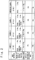
- FIG. 2 is a table showing a production condition of the sample. Samples of embodiments 1-3 and a sample of comparison example 1 were produced. As the base material, the carbon fiber felt was used in all the samples.
- the material solution used for producing the samples two kinds of material solution were prepared.
- the solution is prepared in which the granular resin (the spherical resin) formed of cured phenol resin is dispersed in the resol varnish in which the resol was dissolved in methanol.
- the granular resin the spherical resin of about 10 ⁇ m in diameter was used.
- the content of the resol and the content of the granular resin in the material solution were 1 mass% in either case.
- the content of the resol was 2.0 mass% in the material solution and the content of the granular resin was 5.0 mass%.
- the content of the resol and the content of the granular resin in the material solution was 2.5 mass% in either case.
- the resol varnish was used in which the resol was dissolved in methanol. Note that any granular resin is not contained in the material solution which is used for producing the ablator of the comparison example. In the comparison example, the content of the resol in the material solution was 5.0 mass%.
- the base material is impregnated in each of the above-mentioned material solutions. Moreover, the solvent is evaporated by air-drying from the material solution impregnated in the base material. Moreover, the resol was cured by heating and a sample was produced.
- the column of "mass change" in the table of FIG. 2 indicates the mass of original base material and the mass of the sample which was finally produced.
- the mass of original base material is 1.75 g and the mass of sample which was finally produced is 2.05 g.
- the same results as the above case are obtained in the embodiments 2 and 3 and the comparison example.
- the difference between the mass of ablator finally produced and the mass of original base material is a mass of resin finally contained in the ablator.
- the column of the "ratio of mass of resin to mass of base material" in the table of FIG. 2 shows a ratio of the mass of resin finally contained in the ablator to the mass of base material.
- the mass of resin finally contained in the ablator is equal to a total of the mass of binder resin and the mass of granular resin, with respect to the samples of the embodiments 1-3.
- the mass of resin finally contained in the ablator is equal to the mass of binder resin.
- a rate of the mass of resin to the mass of base material (that is, a total of the mass of binder resin to the mass of base material) was 32%, but the ablator having no flexibility was produced.
- the rate of the mass of resin to the mass of base material (that is, a ratio of a total of the mass of spherical resin and the mass of binder resin to the mass of base material) is 17%, and the ablator having the flexibility was produced.
- the rates of the mass of resin to the mass of base material are 53% and 56%, respectively.
- the total content of resin contained in the sample is more than in the comparison example 1 but the samples of the embodiments 2 and 3 showed the flexibility. This means that the ablator of the present embodiment which contains the granular resin (the spherical resin) has the flexibility and moreover can improve the fuselage protection performance.
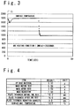
- FIG. 3 and FIG. 4 show the results when an arc heating test is carried out to the sample of the embodiment 2.
- the arc heating test is a method used to test the heat resistance of the ablator to the aerodynamic heating at the time of the re-entry, and it is a technique of heating the sample by the arc heating and of testing the heat resistance of the sample.
- the arc discharge was carried out in the power density of 1.2 MW/m 2 to carry out the arc heating for 25 seconds.
- FIG. 3 is a graph showing the change of the surface temperature of the sample for 50 seconds in the arc heating test. In the first 25 seconds, the arc heating is carried out and in the second 25 seconds, the arc heating has been stopped. By the arc heating, the surface temperature rose and the maximum temperature of the surface reached 1817 °C. After that, after the arc heating is stopped, the surface temperature decreases and became less than 1000 °C.
- the mass was 5.09 g and the board thickness was 19.2 mm.
- the mass of the sample decreased to 3.59 g and the board thickness decreased to 16.0 mm.
- the decrease of the mass was 1.50 g and the decrease of the board thickness was 3.2 mm. This result shows that the sample of the embodiment 2 has the heat resistance required for the ablator.
Landscapes
- Engineering & Computer Science (AREA)
- Mechanical Engineering (AREA)
- Remote Sensing (AREA)
- Chemical & Material Sciences (AREA)
- Composite Materials (AREA)
- Aviation & Aerospace Engineering (AREA)
- Health & Medical Sciences (AREA)
- Thermal Sciences (AREA)
- Physics & Mathematics (AREA)
- Critical Care (AREA)
- Emergency Medicine (AREA)
- General Health & Medical Sciences (AREA)
- Oral & Maxillofacial Surgery (AREA)
- Reinforced Plastic Materials (AREA)
- Moulding By Coating Moulds (AREA)
Abstract
Description
- The present invention relates to an ablator, a re-entry vehicle and a method of manufacturing them.
- An ablator is attached to a re-entry vehicle which carries out a reentry from the space to the atmosphere (e.g. a re-entry recovery capsule and a space go and return vehicle) to protect a fuselage of the vehicle from the aerodynamic heating upon reentering. The ablator is a structure that blocks off the transfer of heat to the fuselage main unit by pyrolyzation, and generally, is formed of resin or a composite material of resin and inorganic substance (fiber). For example, Patent Literature 1 (
JP 2013-121786A JP H09-316217A - Also, Non-Patent Literature 1 (Miread Stackpoole et al., "Development of Low Density Flexible Carbon Phenolic Ablators", NSMMS-2011, June 27-30, 2011, Madison, WI) discloses an ablator having flexibility. The general ablator manufactured by curing resin does not have the flexibility. Accordingly, the ablator needs to be shaped to fit to the fuselage shape by using a jig (e.g. a mold), or to carry out cut processing and polish processing to fit to the fuselage shape after the curing. However, such a technique requires a jig cost and a processing cost and there is a problem with respect to the cost. On the other hand, the ablator having the flexibility is possible to transform the ablator according to the fuselage shape when attaching to the fuselage. Accordingly, the jig and the processing to fit to the fuselage shape are unnecessary, so that it is effective in the reduction of cost. The ablator disclosed in Non-Patent
Literature 1 is composed of carbon fiber (fiber form and felt) and phenol resin impregnated in the fiber. Note that the ablator having the flexibility is also disclosed in Patent Literature 3 (US 7,931,962 ). -
- [Patent Literature 1]
-
JP 2013-121786A - [Patent Literature 2]
-
JP H09-316217A - [Patent literature 3]
-
US 7,931,962 - [Non-patent literature 1] Miread Stackpoole et al., "Development of Low Density Flexible Carbon Phenolic Ablators", NSMMS-2011, June 27-30 2011, Madison, WI http://ntrs.nasa.gov/archive/nasa/casi.ntrs.nasa.gov/2 0110015026_2011015871.pdf
- In a technique disclosed in
Non-Patent Literature 1, it becomes necessary to reduce the content of phenol resin to a relatively small quantity in order to give the necessary flexibility to the ablator. On the other hand, because the ablator protects the fuselage through pyrolyzation of the ablator, the reduction of the content of the phenol resin causes the reduction in the performance to protect the fuselage from the aerodynamic heating. - Therefore, an object of the present invention is to provide an ablator to improve the fuselage protection performance while having the flexibility.
- According to an aspect of the present invention, the ablator contains base material formed of fiber, granular resin, and binder resin that is impregnated in the base material to couple the granular resin and the base material.
- A quantity of binder resin contained in the ablator is adjusted for the ablator to have flexibility.
- It is desirable that spherical resin is used as the granular resin. Also, it is desirable that each of the granular resin and the binder resin is produced from any of phenol resin, fran resin, and mixture resin of them. Also, it is desirable that the base material is produced from carbon fiber.
- According to another aspect of the present invention, a re-entry vehicle is provided with the above-mentioned ablator and a fuselage main unit to which the ablator is installed.
- According to a still another aspect of the present invention, a method of manufacturing the ablator includes impregnating the base material with a material solution that contains uncured resin and cured granular resin, and curing the uncured resin after impregnating the base material with the material solution.
- According to another aspect of the present invention, a method of manufacturing a re-entry vehicle includes manufacturing the ablator; and installing the ablator on the fuselage main unit. The method of manufacturing the ablator includes impregnating the base material with the material solution which contains uncured resin and cured granular resin; and curing the uncured resin after the impregnating the base material with the material solution.
- According to the present invention, the ablator is provided to improve the fuselage protection performance while having the flexibility.
-
- [
FIG. 1 ]
FIG. 1 is a conceptual diagram showing a method of manufacturing an ablator and a re-entry vehicle according to an embodiment of the present invention. - [
FIG. 2 ]
FIG. 2 is a table indicating a production condition of the ablator according to the embodiment of the present invention and a comparison example. - [
FIG. 3 ]
FIG. 3 is a graph showing the result of an arc heating test according to the embodiment of the present invention. - [
FIG. 4 ]
FIG. 4 is a table indicating the result of the arc heating test according to the embodiment of the present invention. - Hereinafter, an ablator and a method of manufacturing the ablator according to an embodiment the present invention will be described with reference to the attached drawings.
- According to the embodiment of the present invention, the ablator contains a base material formed from fiber, granular resin, and binder resin impregnating in the fiber to couple and combine the granular resin and the base material.
- As the fiber which configures the base material, for example, any of carbon fiber (CF), glass fiber, silica fiber, basalt fiber, PBO (Poly-p-phenylene benzoxazole) fiber, alumina fiber, and tyranno fiber (registered trademark of Ube Industries, Ltd.) can be used. From the viewpoint of the improvement of heat resistance of a re-entry vehicle, it is desirable to use the carbon fiber as the fiber configuring the base material. In the embodiment, as the base material, carbon fiber felt can be used in which non-woven cloth of the carbon fiber is laminated for two or more layers and the laminated non-woven is confounded with a needle punch.
- Also, as the granular resin, it is desirable to use spherical resin (resin of spherical particles). In other words, it is desirable that the shape of each particle of the granular resign is spherical. By using the spherical resin as the granular resin, it becomes easy for the granular resin to prevail in the whole fiber of the base material. In the embodiment, for example, the spherical resin of about 10-µm diameter can be used as the granular resin.
- As the materials of the granular resin and the binder resin, for example, any of phenol resin, fran resin, mixture resin of the phenol resin and the fran resin, and epoxy resin can be used. From the viewpoint of the improvement of heat resistance of the re-entry vehicle, any of the phenol resin, the fran resin, and the mixture resin of the phenol resin and the fran resin is desirable as the material of the granular resin or the binder resin. The phenol resin and the fran resin are generally superior in the heat resistance. By using any of the phenol resin, the fran resin and the mixture resin of them for the granular resin and the binder resin, the fuselage protection performance of the ablator can be improved.
- According to the structure of the ablator in the present embodiment, it is possible to improve the fuselage protection performance while the ablator has the flexibility, by adjusting or controlling the contents of the granular resin and the binder resin appropriately. When the content of the binder resin is high, the coupling between the fibers becomes firm so that the ablator becomes a rigid body (that is, the flexibility is lost). On the contrary, when the content of the binder resin is low, the coupling between the fibers becomes weak so that the ablator can have the flexibility. In the ablator of the present embodiment, by adjusting the content of the binder resin, the coupling between the fibers by the binder resin becomes weak so that the flexibility is given to the ablator.
- On the other hand, the heat resistance of the ablator, i.e. the fuselage protection performance depends on the content of the granular resin in addition to the content of the binder resin. Note that the granular resin does not contribute to the coupling between the fibers too much. Even if the ablator contains the granular resin, the ablator does not lose the flexibility. In other words, even if the content of the binder resin is low, the heat resistance of the ablator, i.e. the fuselage protection performance can be improved by adding the granular resin. In this way, according to the configuration of the ablator in the present embodiment, the content of the binder resin is reduced in a range that the ablator has the flexibility and the fuselage protection performance can be sufficiently ensured, by adding the granular resin of an appropriate quantity to the ablator.
-
FIG. 1 is a conceptual diagram showing the method of manufacturing the ablator and the re-entry vehicle in the embodiment. As shown in (a) ofFIG. 1 , first, feltbase material 1 is produced. When the ablator is configured from a plurality of ablator members, a pattern is made according to the shape of a fuselage main unit of the re-entry vehicle, and the feltbase material 1 corresponding to the plurality of ablator members according to the pattern is produced. As mentioned above, the feltbase material 1 may be formed from carbon fiber or glass fiber. - Next, as shown in (b) of
FIG. 1 , the impregnation of the resin into the feltbase material 1 is carried out. More specifically, material solution is prepared in which uncured resin is dissolved and granular resin (spherical resin) is dispersed. The feltbase material 1 is impregnated with the material solution. Thus, the feltbase material 1 is impregnated with the material solution. As mentioned later, the uncured resin which is contained in the material solution is cured in the following process to function as the binder resin which is contained in the ablator. On the other hand, as the granular resin (the spherical resin) which is contained in the material solution, the cured resin is used. This means that the granular resin does not have a function to couple the fibers of the feltbase material 1 to each other directly. - In the present embodiment, resol is used as the uncured resin. This means that the phenol resin is used as the binder resin which is finally contained in the ablator. On the other hand, as the granular resin, the already cured phenol resin or fran resin is used. Also, as the solvent in which the uncured resin is dissolved, methanol is used. That is, in the present embodiment, the solution in which the granular resin (the spherical resin) formed of the cured phenol resin or fran resin is dispersed in the resol varnish that the resol has been dissolved in methanol, is used as the material solution. As the granular resin, for example, the spherical resin with 10-µm diameter is used.
- The content of the binder resin which is contained in the ablator is adjustable based on the content of the uncured resin which is contained in material solution (the content of the resol which is contained in the material solution in the present embodiment). The content of the uncured resin which is contained in the material solution is adjusted such that the finally made ablator has the flexibility.
- Next, as shown in (c) of
FIG. 1 , the solvent of the material solution that has been impregnated in the feltbase material 1 is evaporated by air-drying. In the present embodiment that solution in which the granular resin formed from the cured phenol resin or fran resin has been dispersed in the resol varnish is used as the material solution, the methanol of the solvent which is contained in the resol varnish is evaporated by the air-drying. - Next, as shown in (d) of
FIG. 1 , the uncured resin that has been impregnated in the feltbase material 1 is cured. In the present embodiment, the resol which has been impregnated in the feltbase material 1 is cured by heating a heating furnace. Thus, theablator members 2 which are used to manufacture a part which configures the ablator are completed. In the present embodiment, an assembly in which the parts produced from theablator members 2 are combined is used as the ablator. - Moreover, as shown in (e) of
FIG. 1 , the ablator is installed to the fuselage main unit 4. In detail, theablator members 2 are cut out to produce theparts 3 which configure the ablator, and thepart 3 is adhered to the fuselage main unit 4 with an adhesive material. In the present embodiment, because theablator member 2 has the flexibility, eachpart 3 can be bent to fit to the shape of the fuselage main unit 4 in case of adhesion of thepart 3 which has been produced from theablator member 2. This means that the ablator can be joined or installed to the fuselage main unit 4 with little labor. When the ablator not having the flexibility is joined to the fuselage main unit, the ablator must be shaped to fit to the shape of the fuselage main unit or cut. On the other hand, in the ablator of the present embodiment which has the flexibility, it is easy to make the ablator fit the shape of the fuselage main unit 4 and, therefore, the cost and work to join the ablator to the fuselage main unit 4 can be reduced. - Below, the embodiment of the present invention will be described.
- A sample was made to have confirmed the ablator of the present invention. As the base material, a carbon fiber felt made to subject to needle punch was used. Also, phenol resin was used as the spherical resin and the binder resin.
-
FIG. 2 is a table showing a production condition of the sample. Samples of embodiments 1-3 and a sample of comparison example 1 were produced. As the base material, the carbon fiber felt was used in all the samples. - As the material solution used for producing the samples, two kinds of material solution were prepared. As the material solution which is used for producing the samples of the embodiments 1-3, the solution is prepared in which the granular resin (the spherical resin) formed of cured phenol resin is dispersed in the resol varnish in which the resol was dissolved in methanol. As the granular resin, the spherical resin of about 10 µm in diameter was used. In the
embodiment 1, the content of the resol and the content of the granular resin in the material solution were 1 mass% in either case. In theembodiment 2, the content of the resol was 2.0 mass% in the material solution and the content of the granular resin was 5.0 mass%. Also, in theembodiment 3, the content of the resol and the content of the granular resin in the material solution was 2.5 mass% in either case. - On the other hand, as the material solution which is used for producing the sample of the comparison example 1, the resol varnish was used in which the resol was dissolved in methanol. Note that any granular resin is not contained in the material solution which is used for producing the ablator of the comparison example. In the comparison example, the content of the resol in the material solution was 5.0 mass%.
- The base material is impregnated in each of the above-mentioned material solutions. Moreover, the solvent is evaporated by air-drying from the material solution impregnated in the base material. Moreover, the resol was cured by heating and a sample was produced.
- The column of "mass change" in the table of
FIG. 2 indicates the mass of original base material and the mass of the sample which was finally produced. For example, in theembodiment 1, the mass of original base material is 1.75 g and the mass of sample which was finally produced is 2.05 g. The same results as the above case are obtained in theembodiments - The column of the "ratio of mass of resin to mass of base material" in the table of
FIG. 2 shows a ratio of the mass of resin finally contained in the ablator to the mass of base material. Here, note that the mass of resin finally contained in the ablator is equal to a total of the mass of binder resin and the mass of granular resin, with respect to the samples of the embodiments 1-3. On the other hand, because the granular resin is not contained in the sample of the comparison example, the mass of resin finally contained in the ablator is equal to the mass of binder resin. - In this case, as mentioned above, because the ratio of the content of resol in the material solution and the content of granular resin is 1:1 in the embodiments 1-3, a half of the resin finally contained in the ablator of the embodiments 1-3 is the binder resin, and the remaining half is estimated to be the granular resin.
- In the comparison example 1, a rate of the mass of resin to the mass of base material (that is, a total of the mass of binder resin to the mass of base material) was 32%, but the ablator having no flexibility was produced.
- On the other hand, in the
embodiment 1, the rate of the mass of resin to the mass of base material (that is, a ratio of a total of the mass of spherical resin and the mass of binder resin to the mass of base material) is 17%, and the ablator having the flexibility was produced. - In the
embodiments embodiments -
FIG. 3 and FIG. 4 show the results when an arc heating test is carried out to the sample of theembodiment 2. The arc heating test is a method used to test the heat resistance of the ablator to the aerodynamic heating at the time of the re-entry, and it is a technique of heating the sample by the arc heating and of testing the heat resistance of the sample. As the condition of the arc heating test, the arc discharge was carried out in the power density of 1.2 MW/m2 to carry out the arc heating for 25 seconds. -
FIG. 3 is a graph showing the change of the surface temperature of the sample for 50 seconds in the arc heating test. In the first 25 seconds, the arc heating is carried out and in the second 25 seconds, the arc heating has been stopped. By the arc heating, the surface temperature rose and the maximum temperature of the surface reached 1817 °C. After that, after the arc heating is stopped, the surface temperature decreases and became less than 1000 °C. - As shown in
FIG. 4 , before the arc heating test, in the sample of theembodiment 2, the mass was 5.09 g and the board thickness was 19.2 mm. After the arc heating test, the mass of the sample decreased to 3.59 g and the board thickness decreased to 16.0 mm. The decrease of the mass was 1.50 g and the decrease of the board thickness was 3.2 mm. This result shows that the sample of theembodiment 2 has the heat resistance required for the ablator. -
- 1: felt base material
- 2: ablator member
- 3: part
- 4: fuselage main unit
Claims (10)
- An ablator comprising:a base material formed from fiber;granular resin; and
binder resin impregnated in the fiber to couple the granular resin and the base material. - The ablator according to claim 1, wherein a content of the binder resin contained in the ablator is adjusted so that the ablator has flexibility.
- The ablator according to claims 1 or 2, wherein the granular resin is spherical.
- The ablator according to any of claims 1 to 3, wherein the granular resin or the binder resin is formed from any of phenol resin, fran resin, and mixture resin of the phenol resin and the fran resin.
- The ablator according to any of claims 1 to 4, wherein the base material is formed from any of carbon fiber, glass fiber, silica fiber, basalt fiber, poly-p-phenylene benzoxazole fiber, alumina fiber and tyranno fiber.
- A re-entry vehicle comprising:the ablator according to any of claims 1 to 5; anda fuselage main unit on which the ablator is installed.
- A method of manufacturing an ablator, comprising:impregnating a base material formed from fiber with material solution which contains uncured resin and cured granular resin; andcuring the uncured resin after the impregnating with the material solution.
- The method of manufacturing an ablator according to claim 7, wherein the granular resin is spherical.
- The method of manufacturing an ablator according to claim 7 or 8, wherein each of the granular resin and the binder resin is formed from any of phenol resin, fran resin, and mixture resin of the phenol resin and the fran resin.
- A method of manufacturing a re-entry vehicle comprising:manufacturing an ablator; andinstalling the ablator on a fuselage main unit,wherein the manufacturing the ablator comprises:impregnating a base material formed from fiber with material solution which contains uncured resin and cured granular resin; andcuring the uncured resin after the impregnating with the material solution.
Applications Claiming Priority (2)
| Application Number | Priority Date | Filing Date | Title |
|---|---|---|---|
| JP2014081352A JP6353686B2 (en) | 2014-04-10 | 2014-04-10 | Re-entry machine manufacturing method |
| PCT/JP2015/061153 WO2015156368A1 (en) | 2014-04-10 | 2015-04-09 | Ablator, reentry vehicle, and methods respectively for manufacturing said ablator and said reentry vehicle |
Publications (3)
| Publication Number | Publication Date |
|---|---|
| EP3130544A1 true EP3130544A1 (en) | 2017-02-15 |
| EP3130544A4 EP3130544A4 (en) | 2017-05-24 |
| EP3130544B1 EP3130544B1 (en) | 2022-06-01 |
Family
ID=54287940
Family Applications (1)
| Application Number | Title | Priority Date | Filing Date |
|---|---|---|---|
| EP15776733.6A Active EP3130544B1 (en) | 2014-04-10 | 2015-04-09 | Ablator, reentry vehicle, and methods respectively for manufacturing said ablator and said reentry vehicle |
Country Status (4)
| Country | Link |
|---|---|
| US (1) | US10647452B2 (en) |
| EP (1) | EP3130544B1 (en) |
| JP (1) | JP6353686B2 (en) |
| WO (1) | WO2015156368A1 (en) |
Cited By (1)
| Publication number | Priority date | Publication date | Assignee | Title |
|---|---|---|---|---|
| CN109955501A (en) * | 2019-04-04 | 2019-07-02 | 北京卫星制造厂有限公司 | Recoverable airship large scale fans cambered surface thermal protection struc ture moulding technique |
Families Citing this family (1)
| Publication number | Priority date | Publication date | Assignee | Title |
|---|---|---|---|---|
| JP6353686B2 (en) * | 2014-04-10 | 2018-07-04 | 三菱重工業株式会社 | Re-entry machine manufacturing method |
Family Cites Families (30)
| Publication number | Priority date | Publication date | Assignee | Title |
|---|---|---|---|---|
| US3520027A (en) * | 1968-07-11 | 1970-07-14 | Dow Chemical Co | Apparatus for the incorporation of filamentary material in resinous matrix |
| US3962491A (en) * | 1972-10-11 | 1976-06-08 | Aisin Chemical Company, Limited | Process for producing resin-coated sand particles for use in shell moles |
| US4151800A (en) * | 1977-04-15 | 1979-05-01 | The United States Of America As Represented By The Administrator Of The National Aeronautics And Space Administration | Thermal insulation protection means |
| US4255483A (en) * | 1977-06-14 | 1981-03-10 | Mcdonnell Douglas Corporation | Fire barrier compositions and composites |
| US4364991A (en) * | 1980-09-25 | 1982-12-21 | Mcdonnell Douglas Corporation | Fire resistant compositions and composites |
| FR2586080B1 (en) * | 1985-08-12 | 1987-11-27 | Centre Nat Etd Spatiales | THERMAL PROTECTION ELEMENT FOR A MACHINE SUBJECT TO IMPORTANT HEATING |
| JP3565370B2 (en) * | 1995-03-31 | 2004-09-15 | 株式会社アイ・エイチ・アイ・エアロスペース | Ablation method and ablator structure |
| JPH09239847A (en) * | 1996-03-14 | 1997-09-16 | Nissan Motor Co Ltd | Low density FRP ablator |
| JP3644612B2 (en) | 1996-05-28 | 2005-05-11 | 株式会社アイ・エイチ・アイ・エアロスペース | Ablator material and manufacturing method thereof |
| US6136418A (en) * | 1999-03-01 | 2000-10-24 | Rotary Rocket Company | Rapidly removable thermal protection system for reusable launch vehicle |
| US6280667B1 (en) * | 1999-04-19 | 2001-08-28 | Andersen Corporation | Process for making thermoplastic-biofiber composite materials and articles including a poly(vinylchloride) component |
| US6264144B1 (en) * | 1999-08-03 | 2001-07-24 | Lockheed Martin Corporation | Material assembly for an inflatable aerodynamic braking device for spacecraft deceleration and the like |
| JP3559797B2 (en) * | 2000-03-07 | 2004-09-02 | 独立行政法人 宇宙航空研究開発機構 | Ablator |
| CN1301757C (en) * | 2001-11-27 | 2007-02-28 | 多喜兰株式会社 | Implant material and method for its production |
| US20040096619A1 (en) * | 2002-11-11 | 2004-05-20 | The Boeing Company | Flexible insulation blanket having a ceramic matrix composite outer layer |
| WO2004072175A1 (en) * | 2003-02-13 | 2004-08-26 | Orient Chemical Industries, Ltd. | Laser light trnasmitting colored polyolefin resin compositions and process for laser welding |
| US7219859B2 (en) * | 2005-04-01 | 2007-05-22 | Spacehab, Incorporated | Multipurpose modular spacecraft |
| US9040646B2 (en) * | 2007-10-04 | 2015-05-26 | W. L. Gore & Associates, Inc. | Expandable TFE copolymers, methods of making, and porous, expanded articles thereof |
| JP5263737B2 (en) * | 2008-07-15 | 2013-08-14 | 独立行政法人国立高等専門学校機構 | Method for producing thermal protection composite material |
| US7931962B1 (en) * | 2009-05-14 | 2011-04-26 | Lockheed Martin Corporation | Pyrolizing flexible ablator material |
| JP5878298B2 (en) * | 2011-03-02 | 2016-03-08 | リグナイト株式会社 | Thermal insulation composition and thermal insulation |
| US9592923B1 (en) * | 2011-10-24 | 2017-03-14 | The United States Of America As Represented By The Administrator Of The National Aeronautics And Space Administration | Flexible ablators |
| JP5727923B2 (en) | 2011-12-12 | 2015-06-03 | 川崎重工業株式会社 | Ablator |
| JP6253871B2 (en) * | 2012-01-17 | 2017-12-27 | 三菱重工業株式会社 | Insulating material, spacecraft equipped with the same, and method of manufacturing the insulating material |
| JP5590686B2 (en) * | 2012-07-25 | 2014-09-17 | 独立行政法人国立高等専門学校機構 | Method for producing thermal protection composite material |
| US9656769B2 (en) * | 2013-05-01 | 2017-05-23 | Mohammad A. Mazed | Heat shield for a spacecraft |
| JP6353686B2 (en) * | 2014-04-10 | 2018-07-04 | 三菱重工業株式会社 | Re-entry machine manufacturing method |
| US9522747B2 (en) * | 2014-06-03 | 2016-12-20 | Analytical Mechanics Associates, Inc. | Inflatable deceleration apparatus |
| US9475261B2 (en) * | 2014-08-18 | 2016-10-25 | The Boeing Company | Dual layer sandwich for thermal management |
| US9475593B2 (en) * | 2014-08-18 | 2016-10-25 | The Boeing Company | Dual layer sandwich for thermal management |
-
2014
- 2014-04-10 JP JP2014081352A patent/JP6353686B2/en active Active
-
2015
- 2015-04-09 WO PCT/JP2015/061153 patent/WO2015156368A1/en not_active Ceased
- 2015-04-09 US US15/302,292 patent/US10647452B2/en active Active
- 2015-04-09 EP EP15776733.6A patent/EP3130544B1/en active Active
Cited By (2)
| Publication number | Priority date | Publication date | Assignee | Title |
|---|---|---|---|---|
| CN109955501A (en) * | 2019-04-04 | 2019-07-02 | 北京卫星制造厂有限公司 | Recoverable airship large scale fans cambered surface thermal protection struc ture moulding technique |
| CN109955501B (en) * | 2019-04-04 | 2021-06-11 | 北京卫星制造厂有限公司 | Forming process method of large-size sector arc surface heat-proof structure of return airship |
Also Published As
| Publication number | Publication date |
|---|---|
| US10647452B2 (en) | 2020-05-12 |
| US20170029140A1 (en) | 2017-02-02 |
| JP6353686B2 (en) | 2018-07-04 |
| WO2015156368A1 (en) | 2015-10-15 |
| JP2015202701A (en) | 2015-11-16 |
| EP3130544B1 (en) | 2022-06-01 |
| EP3130544A4 (en) | 2017-05-24 |
Similar Documents
| Publication | Publication Date | Title |
|---|---|---|
| EP2432634B1 (en) | Method for forming a structure having a lightning strike protection and lightning strike protection structure | |
| KR101072287B1 (en) | Method of manufacturing high temperature insulation flexible blanket formed of silica aerogel with non-woven glass fibre batting and, the blanket manufactured by the method | |
| US20120227247A1 (en) | Controlling Temperature in Exothermic Reactions with a Phase Change Material | |
| US20030205310A1 (en) | Method of producing a multi-layer ceramic fiber insulation tile | |
| JP6466459B2 (en) | Electrical conductor and method of forming electrical conductor | |
| US20180016028A1 (en) | Heating Layer For Film Removal | |
| US9849965B2 (en) | Manufacturing method of reinforced structure | |
| US20160325857A1 (en) | Hybrid ablative thermal protection systems and associated methods | |
| US10647452B2 (en) | Ablator, re-entry vehicle and method of manufacturing them | |
| KR101284810B1 (en) | Reinforced composite part composed of an assembly of at least two different composite members | |
| EP3020539A1 (en) | Method for producing reinforcing structure | |
| EP3705271B1 (en) | Method for bonding composite material | |
| JP2013028166A (en) | Method of manufacturing thermal protection composite material | |
| US9827744B2 (en) | Lightning strike protection material for dry lay-up / dry fiber placement device | |
| US20070089285A1 (en) | Method for manufacturing a structurally integrated antenna | |
| KR20170116470A (en) | Fiber complex material structure | |
| KR20120004853A (en) | How to improve adhesion between rubber and epoxy resin-containing composite | |
| US6066389A (en) | Connector tow | |
| RU2014135596A (en) | TEMPORARY RETAINING OF THE METAL SHEET ON THE FORM WITH THE help of MICROWELDS | |
| CN207916217U (en) | A kind of fiber reinforcement type high performance composite film | |
| US10274005B2 (en) | Induction-softened thermoplastic shims | |
| US11571864B2 (en) | Methods of creating composite parts with fibers in a desired orientation | |
| EP3278963A1 (en) | Structural body production method and structural body | |
| JP2015202701A5 (en) | ||
| US20250296891A1 (en) | Composite articles comprising a thermal protection structure, and related methods |
Legal Events
| Date | Code | Title | Description |
|---|---|---|---|
| STAA | Information on the status of an ep patent application or granted ep patent |
Free format text: STATUS: THE INTERNATIONAL PUBLICATION HAS BEEN MADE |
|
| PUAI | Public reference made under article 153(3) epc to a published international application that has entered the european phase |
Free format text: ORIGINAL CODE: 0009012 |
|
| STAA | Information on the status of an ep patent application or granted ep patent |
Free format text: STATUS: REQUEST FOR EXAMINATION WAS MADE |
|
| 17P | Request for examination filed |
Effective date: 20161109 |
|
| AK | Designated contracting states |
Kind code of ref document: A1 Designated state(s): AL AT BE BG CH CY CZ DE DK EE ES FI FR GB GR HR HU IE IS IT LI LT LU LV MC MK MT NL NO PL PT RO RS SE SI SK SM TR |
|
| AX | Request for extension of the european patent |
Extension state: BA ME |
|
| A4 | Supplementary search report drawn up and despatched |
Effective date: 20170425 |
|
| RIC1 | Information provided on ipc code assigned before grant |
Ipc: B29C 70/02 20060101ALI20170419BHEP Ipc: B29C 70/06 20060101ALI20170419BHEP Ipc: B64G 1/58 20060101AFI20170419BHEP Ipc: B29L 31/30 20060101ALI20170419BHEP Ipc: B29K 105/08 20060101ALI20170419BHEP |
|
| DAV | Request for validation of the european patent (deleted) | ||
| DAX | Request for extension of the european patent (deleted) | ||
| STAA | Information on the status of an ep patent application or granted ep patent |
Free format text: STATUS: EXAMINATION IS IN PROGRESS |
|
| 17Q | First examination report despatched |
Effective date: 20210412 |
|
| GRAP | Despatch of communication of intention to grant a patent |
Free format text: ORIGINAL CODE: EPIDOSNIGR1 |
|
| STAA | Information on the status of an ep patent application or granted ep patent |
Free format text: STATUS: GRANT OF PATENT IS INTENDED |
|
| INTG | Intention to grant announced |
Effective date: 20211216 |
|
| GRAS | Grant fee paid |
Free format text: ORIGINAL CODE: EPIDOSNIGR3 |
|
| GRAA | (expected) grant |
Free format text: ORIGINAL CODE: 0009210 |
|
| STAA | Information on the status of an ep patent application or granted ep patent |
Free format text: STATUS: THE PATENT HAS BEEN GRANTED |
|
| RAP1 | Party data changed (applicant data changed or rights of an application transferred) |
Owner name: LIGNYTE CO., LTD. |
|
| AK | Designated contracting states |
Kind code of ref document: B1 Designated state(s): AL AT BE BG CH CY CZ DE DK EE ES FI FR GB GR HR HU IE IS IT LI LT LU LV MC MK MT NL NO PL PT RO RS SE SI SK SM TR |
|
| REG | Reference to a national code |
Ref country code: GB Ref legal event code: FG4D |
|
| REG | Reference to a national code |
Ref country code: AT Ref legal event code: REF Ref document number: 1495246 Country of ref document: AT Kind code of ref document: T Effective date: 20220615 Ref country code: CH Ref legal event code: EP |
|
| REG | Reference to a national code |
Ref country code: IE Ref legal event code: FG4D |
|
| REG | Reference to a national code |
Ref country code: DE Ref legal event code: R096 Ref document number: 602015079259 Country of ref document: DE |
|
| REG | Reference to a national code |
Ref country code: LT Ref legal event code: MG9D |
|
| REG | Reference to a national code |
Ref country code: NL Ref legal event code: MP Effective date: 20220601 |
|
| PG25 | Lapsed in a contracting state [announced via postgrant information from national office to epo] |
Ref country code: SE Free format text: LAPSE BECAUSE OF FAILURE TO SUBMIT A TRANSLATION OF THE DESCRIPTION OR TO PAY THE FEE WITHIN THE PRESCRIBED TIME-LIMIT Effective date: 20220601 Ref country code: NO Free format text: LAPSE BECAUSE OF FAILURE TO SUBMIT A TRANSLATION OF THE DESCRIPTION OR TO PAY THE FEE WITHIN THE PRESCRIBED TIME-LIMIT Effective date: 20220901 Ref country code: LT Free format text: LAPSE BECAUSE OF FAILURE TO SUBMIT A TRANSLATION OF THE DESCRIPTION OR TO PAY THE FEE WITHIN THE PRESCRIBED TIME-LIMIT Effective date: 20220601 Ref country code: HR Free format text: LAPSE BECAUSE OF FAILURE TO SUBMIT A TRANSLATION OF THE DESCRIPTION OR TO PAY THE FEE WITHIN THE PRESCRIBED TIME-LIMIT Effective date: 20220601 Ref country code: GR Free format text: LAPSE BECAUSE OF FAILURE TO SUBMIT A TRANSLATION OF THE DESCRIPTION OR TO PAY THE FEE WITHIN THE PRESCRIBED TIME-LIMIT Effective date: 20220902 Ref country code: FI Free format text: LAPSE BECAUSE OF FAILURE TO SUBMIT A TRANSLATION OF THE DESCRIPTION OR TO PAY THE FEE WITHIN THE PRESCRIBED TIME-LIMIT Effective date: 20220601 Ref country code: ES Free format text: LAPSE BECAUSE OF FAILURE TO SUBMIT A TRANSLATION OF THE DESCRIPTION OR TO PAY THE FEE WITHIN THE PRESCRIBED TIME-LIMIT Effective date: 20220601 Ref country code: BG Free format text: LAPSE BECAUSE OF FAILURE TO SUBMIT A TRANSLATION OF THE DESCRIPTION OR TO PAY THE FEE WITHIN THE PRESCRIBED TIME-LIMIT Effective date: 20220901 |
|
| REG | Reference to a national code |
Ref country code: AT Ref legal event code: MK05 Ref document number: 1495246 Country of ref document: AT Kind code of ref document: T Effective date: 20220601 |
|
| PG25 | Lapsed in a contracting state [announced via postgrant information from national office to epo] |
Ref country code: RS Free format text: LAPSE BECAUSE OF FAILURE TO SUBMIT A TRANSLATION OF THE DESCRIPTION OR TO PAY THE FEE WITHIN THE PRESCRIBED TIME-LIMIT Effective date: 20220601 Ref country code: PL Free format text: LAPSE BECAUSE OF FAILURE TO SUBMIT A TRANSLATION OF THE DESCRIPTION OR TO PAY THE FEE WITHIN THE PRESCRIBED TIME-LIMIT Effective date: 20220601 Ref country code: LV Free format text: LAPSE BECAUSE OF FAILURE TO SUBMIT A TRANSLATION OF THE DESCRIPTION OR TO PAY THE FEE WITHIN THE PRESCRIBED TIME-LIMIT Effective date: 20220601 |
|
| PG25 | Lapsed in a contracting state [announced via postgrant information from national office to epo] |
Ref country code: NL Free format text: LAPSE BECAUSE OF FAILURE TO SUBMIT A TRANSLATION OF THE DESCRIPTION OR TO PAY THE FEE WITHIN THE PRESCRIBED TIME-LIMIT Effective date: 20220601 |
|
| PG25 | Lapsed in a contracting state [announced via postgrant information from national office to epo] |
Ref country code: SM Free format text: LAPSE BECAUSE OF FAILURE TO SUBMIT A TRANSLATION OF THE DESCRIPTION OR TO PAY THE FEE WITHIN THE PRESCRIBED TIME-LIMIT Effective date: 20220601 Ref country code: SK Free format text: LAPSE BECAUSE OF FAILURE TO SUBMIT A TRANSLATION OF THE DESCRIPTION OR TO PAY THE FEE WITHIN THE PRESCRIBED TIME-LIMIT Effective date: 20220601 Ref country code: RO Free format text: LAPSE BECAUSE OF FAILURE TO SUBMIT A TRANSLATION OF THE DESCRIPTION OR TO PAY THE FEE WITHIN THE PRESCRIBED TIME-LIMIT Effective date: 20220601 Ref country code: PT Free format text: LAPSE BECAUSE OF FAILURE TO SUBMIT A TRANSLATION OF THE DESCRIPTION OR TO PAY THE FEE WITHIN THE PRESCRIBED TIME-LIMIT Effective date: 20221003 Ref country code: EE Free format text: LAPSE BECAUSE OF FAILURE TO SUBMIT A TRANSLATION OF THE DESCRIPTION OR TO PAY THE FEE WITHIN THE PRESCRIBED TIME-LIMIT Effective date: 20220601 Ref country code: CZ Free format text: LAPSE BECAUSE OF FAILURE TO SUBMIT A TRANSLATION OF THE DESCRIPTION OR TO PAY THE FEE WITHIN THE PRESCRIBED TIME-LIMIT Effective date: 20220601 Ref country code: AT Free format text: LAPSE BECAUSE OF FAILURE TO SUBMIT A TRANSLATION OF THE DESCRIPTION OR TO PAY THE FEE WITHIN THE PRESCRIBED TIME-LIMIT Effective date: 20220601 |
|
| PG25 | Lapsed in a contracting state [announced via postgrant information from national office to epo] |
Ref country code: IS Free format text: LAPSE BECAUSE OF FAILURE TO SUBMIT A TRANSLATION OF THE DESCRIPTION OR TO PAY THE FEE WITHIN THE PRESCRIBED TIME-LIMIT Effective date: 20221001 |
|
| REG | Reference to a national code |
Ref country code: DE Ref legal event code: R097 Ref document number: 602015079259 Country of ref document: DE |
|
| PG25 | Lapsed in a contracting state [announced via postgrant information from national office to epo] |
Ref country code: AL Free format text: LAPSE BECAUSE OF FAILURE TO SUBMIT A TRANSLATION OF THE DESCRIPTION OR TO PAY THE FEE WITHIN THE PRESCRIBED TIME-LIMIT Effective date: 20220601 |
|
| PLBE | No opposition filed within time limit |
Free format text: ORIGINAL CODE: 0009261 |
|
| STAA | Information on the status of an ep patent application or granted ep patent |
Free format text: STATUS: NO OPPOSITION FILED WITHIN TIME LIMIT |
|
| PG25 | Lapsed in a contracting state [announced via postgrant information from national office to epo] |
Ref country code: DK Free format text: LAPSE BECAUSE OF FAILURE TO SUBMIT A TRANSLATION OF THE DESCRIPTION OR TO PAY THE FEE WITHIN THE PRESCRIBED TIME-LIMIT Effective date: 20220601 |
|
| 26N | No opposition filed |
Effective date: 20230302 |
|
| PG25 | Lapsed in a contracting state [announced via postgrant information from national office to epo] |
Ref country code: SI Free format text: LAPSE BECAUSE OF FAILURE TO SUBMIT A TRANSLATION OF THE DESCRIPTION OR TO PAY THE FEE WITHIN THE PRESCRIBED TIME-LIMIT Effective date: 20220601 |
|
| REG | Reference to a national code |
Ref country code: CH Ref legal event code: PL |
|
| GBPC | Gb: european patent ceased through non-payment of renewal fee |
Effective date: 20230409 |
|
| PG25 | Lapsed in a contracting state [announced via postgrant information from national office to epo] |
Ref country code: LU Free format text: LAPSE BECAUSE OF NON-PAYMENT OF DUE FEES Effective date: 20230409 |
|
| REG | Reference to a national code |
Ref country code: BE Ref legal event code: MM Effective date: 20230430 |
|
| PG25 | Lapsed in a contracting state [announced via postgrant information from national office to epo] |
Ref country code: MC Free format text: LAPSE BECAUSE OF FAILURE TO SUBMIT A TRANSLATION OF THE DESCRIPTION OR TO PAY THE FEE WITHIN THE PRESCRIBED TIME-LIMIT Effective date: 20220601 |
|
| PG25 | Lapsed in a contracting state [announced via postgrant information from national office to epo] |
Ref country code: GB Free format text: LAPSE BECAUSE OF NON-PAYMENT OF DUE FEES Effective date: 20230409 |
|
| PG25 | Lapsed in a contracting state [announced via postgrant information from national office to epo] |
Ref country code: MC Free format text: LAPSE BECAUSE OF FAILURE TO SUBMIT A TRANSLATION OF THE DESCRIPTION OR TO PAY THE FEE WITHIN THE PRESCRIBED TIME-LIMIT Effective date: 20220601 Ref country code: LI Free format text: LAPSE BECAUSE OF NON-PAYMENT OF DUE FEES Effective date: 20230430 Ref country code: IT Free format text: LAPSE BECAUSE OF FAILURE TO SUBMIT A TRANSLATION OF THE DESCRIPTION OR TO PAY THE FEE WITHIN THE PRESCRIBED TIME-LIMIT Effective date: 20220601 Ref country code: GB Free format text: LAPSE BECAUSE OF NON-PAYMENT OF DUE FEES Effective date: 20230409 Ref country code: CH Free format text: LAPSE BECAUSE OF NON-PAYMENT OF DUE FEES Effective date: 20230430 |
|
| REG | Reference to a national code |
Ref country code: IE Ref legal event code: MM4A |
|
| PG25 | Lapsed in a contracting state [announced via postgrant information from national office to epo] |
Ref country code: BE Free format text: LAPSE BECAUSE OF NON-PAYMENT OF DUE FEES Effective date: 20230430 |
|
| PG25 | Lapsed in a contracting state [announced via postgrant information from national office to epo] |
Ref country code: IE Free format text: LAPSE BECAUSE OF NON-PAYMENT OF DUE FEES Effective date: 20230409 |
|
| PG25 | Lapsed in a contracting state [announced via postgrant information from national office to epo] |
Ref country code: IE Free format text: LAPSE BECAUSE OF NON-PAYMENT OF DUE FEES Effective date: 20230409 |
|
| PG25 | Lapsed in a contracting state [announced via postgrant information from national office to epo] |
Ref country code: BG Free format text: LAPSE BECAUSE OF FAILURE TO SUBMIT A TRANSLATION OF THE DESCRIPTION OR TO PAY THE FEE WITHIN THE PRESCRIBED TIME-LIMIT Effective date: 20220601 |
|
| PG25 | Lapsed in a contracting state [announced via postgrant information from national office to epo] |
Ref country code: BG Free format text: LAPSE BECAUSE OF FAILURE TO SUBMIT A TRANSLATION OF THE DESCRIPTION OR TO PAY THE FEE WITHIN THE PRESCRIBED TIME-LIMIT Effective date: 20220601 |
|
| PGFP | Annual fee paid to national office [announced via postgrant information from national office to epo] |
Ref country code: DE Payment date: 20250422 Year of fee payment: 11 |
|
| PGFP | Annual fee paid to national office [announced via postgrant information from national office to epo] |
Ref country code: FR Payment date: 20250425 Year of fee payment: 11 |
|
| PG25 | Lapsed in a contracting state [announced via postgrant information from national office to epo] |
Ref country code: CY Free format text: LAPSE BECAUSE OF FAILURE TO SUBMIT A TRANSLATION OF THE DESCRIPTION OR TO PAY THE FEE WITHIN THE PRESCRIBED TIME-LIMIT; INVALID AB INITIO Effective date: 20150409 |
|
| PG25 | Lapsed in a contracting state [announced via postgrant information from national office to epo] |
Ref country code: HU Free format text: LAPSE BECAUSE OF FAILURE TO SUBMIT A TRANSLATION OF THE DESCRIPTION OR TO PAY THE FEE WITHIN THE PRESCRIBED TIME-LIMIT; INVALID AB INITIO Effective date: 20150409 |
|
| PG25 | Lapsed in a contracting state [announced via postgrant information from national office to epo] |
Ref country code: TR Free format text: LAPSE BECAUSE OF FAILURE TO SUBMIT A TRANSLATION OF THE DESCRIPTION OR TO PAY THE FEE WITHIN THE PRESCRIBED TIME-LIMIT Effective date: 20220601 |