EP3130543A1 - Cooling apparatus for cooling electronic device in aircraft - Google Patents
Cooling apparatus for cooling electronic device in aircraft Download PDFInfo
- Publication number
- EP3130543A1 EP3130543A1 EP15831480.7A EP15831480A EP3130543A1 EP 3130543 A1 EP3130543 A1 EP 3130543A1 EP 15831480 A EP15831480 A EP 15831480A EP 3130543 A1 EP3130543 A1 EP 3130543A1
- Authority
- EP
- European Patent Office
- Prior art keywords
- ram air
- cooling
- air channel
- pressurized cabin
- heat
- Prior art date
- Legal status (The legal status is an assumption and is not a legal conclusion. Google has not performed a legal analysis and makes no representation as to the accuracy of the status listed.)
- Granted
Links
Images


Classifications
-
- H—ELECTRICITY
- H05—ELECTRIC TECHNIQUES NOT OTHERWISE PROVIDED FOR
- H05K—PRINTED CIRCUITS; CASINGS OR CONSTRUCTIONAL DETAILS OF ELECTRIC APPARATUS; MANUFACTURE OF ASSEMBLAGES OF ELECTRICAL COMPONENTS
- H05K7/00—Constructional details common to different types of electric apparatus
- H05K7/20—Modifications to facilitate cooling, ventilating, or heating
- H05K7/20845—Modifications to facilitate cooling, ventilating, or heating for automotive electronic casings
- H05K7/20863—Forced ventilation, e.g. on heat dissipaters coupled to components
-
- B—PERFORMING OPERATIONS; TRANSPORTING
- B64—AIRCRAFT; AVIATION; COSMONAUTICS
- B64D—EQUIPMENT FOR FITTING IN OR TO AIRCRAFT; FLIGHT SUITS; PARACHUTES; ARRANGEMENT OR MOUNTING OF POWER PLANTS OR PROPULSION TRANSMISSIONS IN AIRCRAFT
- B64D13/00—Arrangements or adaptations of air-treatment apparatus for aircraft crew or passengers, or freight space
- B64D13/06—Arrangements or adaptations of air-treatment apparatus for aircraft crew or passengers, or freight space the air being conditioned
- B64D13/08—Arrangements or adaptations of air-treatment apparatus for aircraft crew or passengers, or freight space the air being conditioned the air being heated or cooled
-
- B—PERFORMING OPERATIONS; TRANSPORTING
- B64—AIRCRAFT; AVIATION; COSMONAUTICS
- B64D—EQUIPMENT FOR FITTING IN OR TO AIRCRAFT; FLIGHT SUITS; PARACHUTES; ARRANGEMENT OR MOUNTING OF POWER PLANTS OR PROPULSION TRANSMISSIONS IN AIRCRAFT
- B64D47/00—Equipment not otherwise provided for
-
- H—ELECTRICITY
- H05—ELECTRIC TECHNIQUES NOT OTHERWISE PROVIDED FOR
- H05K—PRINTED CIRCUITS; CASINGS OR CONSTRUCTIONAL DETAILS OF ELECTRIC APPARATUS; MANUFACTURE OF ASSEMBLAGES OF ELECTRICAL COMPONENTS
- H05K7/00—Constructional details common to different types of electric apparatus
- H05K7/20—Modifications to facilitate cooling, ventilating, or heating
- H05K7/20845—Modifications to facilitate cooling, ventilating, or heating for automotive electronic casings
- H05K7/20881—Liquid coolant with phase change
-
- B—PERFORMING OPERATIONS; TRANSPORTING
- B64—AIRCRAFT; AVIATION; COSMONAUTICS
- B64D—EQUIPMENT FOR FITTING IN OR TO AIRCRAFT; FLIGHT SUITS; PARACHUTES; ARRANGEMENT OR MOUNTING OF POWER PLANTS OR PROPULSION TRANSMISSIONS IN AIRCRAFT
- B64D13/00—Arrangements or adaptations of air-treatment apparatus for aircraft crew or passengers, or freight space
- B64D13/06—Arrangements or adaptations of air-treatment apparatus for aircraft crew or passengers, or freight space the air being conditioned
- B64D2013/0603—Environmental Control Systems
- B64D2013/0614—Environmental Control Systems with subsystems for cooling avionics
-
- Y—GENERAL TAGGING OF NEW TECHNOLOGICAL DEVELOPMENTS; GENERAL TAGGING OF CROSS-SECTIONAL TECHNOLOGIES SPANNING OVER SEVERAL SECTIONS OF THE IPC; TECHNICAL SUBJECTS COVERED BY FORMER USPC CROSS-REFERENCE ART COLLECTIONS [XRACs] AND DIGESTS
- Y02—TECHNOLOGIES OR APPLICATIONS FOR MITIGATION OR ADAPTATION AGAINST CLIMATE CHANGE
- Y02T—CLIMATE CHANGE MITIGATION TECHNOLOGIES RELATED TO TRANSPORTATION
- Y02T50/00—Aeronautics or air transport
- Y02T50/40—Weight reduction
-
- Y—GENERAL TAGGING OF NEW TECHNOLOGICAL DEVELOPMENTS; GENERAL TAGGING OF CROSS-SECTIONAL TECHNOLOGIES SPANNING OVER SEVERAL SECTIONS OF THE IPC; TECHNICAL SUBJECTS COVERED BY FORMER USPC CROSS-REFERENCE ART COLLECTIONS [XRACs] AND DIGESTS
- Y02—TECHNOLOGIES OR APPLICATIONS FOR MITIGATION OR ADAPTATION AGAINST CLIMATE CHANGE
- Y02T—CLIMATE CHANGE MITIGATION TECHNOLOGIES RELATED TO TRANSPORTATION
- Y02T50/00—Aeronautics or air transport
- Y02T50/50—On board measures aiming to increase energy efficiency
Definitions
- the disclosure herein relates to a cooling device for cooling electronic devices in an aircraft, and in particular to a cooling device that does not require an ambient air introduction system prepared particularly for cooling electronic devices.
- any power transmissions have employed mechanical links in general.
- ailerons When ailerons are to be moved for example, a pilot first moves a control column, a mechanical link next transmits its motion to a hydraulic system, and the hydraulic system then drives the ailerons. From an engine, a gear system extracts part of its driving force and transmits it to a fuel pump, thereby driving the fuel pump.
- IGBTs insulated gate bipolar transistors
- Patent Literatures 1 and 2 disclose arts related to cooling systems for devices in airplanes.
- the cooling device disclosed in the present application is intended to solve these problems.
- a cooling device applicable to an airplane having a pressurized cabin and a ram air channel for cooling an electronic device arranged in the pressurized cabin is comprised of a partition wall separating the pressurized cabin from the ram air channel; and a heat exchanger thermally in contact with the electronic device and exposed to the ram air channel so as to radiate heat to a ram air.
- a cooling device that does not require an ambient air introduction system prepared particularly for cooling electronic devices is provided.
- a cooling system is used for cooling power semiconductors in a power supply system but may be instead used for cooling other devices such as a controller circuit for example.
- an airplane 1 is comprised of a body 3 and main wings 5. A considerable part in the interior of the body 3 is a pressurized cabin where the air is pressurized relative to the atmosphere.
- the airplane 1 is further comprised of engines 7 respectively suspended from the main wings 5.
- Each engine 7 creates thrust force and is as well comprised of a generator 25 to generate alternate current power.
- the alternate current power is led through a feeding line 27 to an electric chamber 9 in the pressurized cabin.
- the power supply system is comprised of converters for converting the alternate current power into direct current power, and is further comprised of inverters for further converting part thereof into alternate current power. These converters and inverters are arranged in the pressurized electric chamber 9. The converted direct current power and the re-converted alternate current power are fed through onboard lines 29 to respective devices 31.
- the airplane 1 is comprised of a pressurizing system in order to supply pressurized air to the pressurized cabin.
- the pressurizing system is generally constituted of an inlet 23 opened at the bottom of the body 3 and a compressor 33 in communication therewith.
- the compressor 33 pressurizes the ambient air A sucked through the inlet 23 up to a pressure close to the atmospheric pressure on the ground and supplies it to the pressurized cabin.
- the ambient air at high altitudes can drop in temperature down to a considerably low temperature (-50 degrees C for example) but, as pressurization by the compressor 33 is adiabatic compression, the pressurized air can rather rise in temperature up to a high temperature (100 degrees C for example).
- the airplane 1 is comprised of a ram air channel 13 in order to cool it down to a temperature comfortable to occupants.
- the ram air channel 13 is comprised of a ram intake 17 opened at the bottom of the body 3, a heat exchanger 35 in communication therewith, and an exhaust port 19 further in communication therewith and opened at the bottom of the body 3.
- Ram air Ar flows through the ram intake 17 into the ram air channel 13, cools the pressurized air at the heat exchanger 35, and is exhausted out as exhaust air Ex through the exhaust port 19 to the exterior.
- respective devices or elements 11 in the power supply system are arranged in the pressurized electric chamber 9 and are thermally in contact with thermal conductors 21 for heat extraction.
- thermal in contact here means not only to have mere structural contact but also to have contact close enough to reduce thermal resistance. This definition is used throughout the description and the appended claims.
- adhesives such as thermal grease are available.
- One or more partition walls 15 air-tightly separate the electric chamber 9 from the ram air channel 13.
- the thermal conductors 21 extend from the electric chamber 9 over the partition walls 15 to the ram air channel 13 and are thus exposed to the ram air channel 13.
- Each thermal conductor 21 has a tip with a structure that increases its surface area, such as a plurality of fins, thereby functioning as a heat exchanger. The tips of the thermal conductors 21 are exposed to the flow of the ram air Ar so as to radiate heat by the respective devices or elements 11 to the ram air Ar.
- Each thermal conductor 21 may be a unitary body from the interior of the electric chamber 9 to the ram air channel 13 and may air-tightly penetrate the partition walls 15. In this configuration, the partition walls 15 may not be required to contribute to heat exchange.
- Each thermal conductor 21 may be an aggregation of plural solid bodies but instead may be a single unitary body. Being a single unitary body is advantageous in light of reduction of thermal resistance.
- Each thermal conductor 21 may be of any thermally conductive substance such as aluminum, copper, silver or carbon (or graphite) to realize sufficiently low thermal resistance, or may be constituted of a heat-transfer device such as a heat pipe in part or totally.
- each thermal conductor 21 may not penetrate the partition walls 15.
- One body of each thermal conductor 21 may be thermally in contact with the partition walls 15 and another body thereof may be thermally in contact with the partition walls 15 so that they transfers heat via the partition walls 15.
- the partition walls 15 constitute a part of the heat transfer path from the devices or elements 11 to the ram air channel 13.
- any thermally conductive substance such as aluminum, copper, silver or carbon (or graphite) can be applied to the partition walls 15.
- the cooling device as described above radiates heat by the respective devices or elements 11 to the ram air Ar through the heat exchanger constituted of the thermal conductors 21 beyond the partition walls 15 separating the pressurized cabin from the ram air channel 13. While the devices or elements 11 are arranged in the pressurized cabin, heat therefrom is soon radiated from the pressurized cabin to the exterior so that the heat does not cause notable temperature rise in the respective devices or elements and the pressurized cabin, or does not affect thermal balance in the pressurized cabin. Further, as the devices or elements 11 are operated in the pressurized air, electric discharge is unlikely to occur even if they use direct current at relatively high voltage.
- the power supply system can use direct current at relatively high voltage and thus realize high energy efficiency.
- This cooling device uses the ram air channel that an airplane normally has and does not require any other special air introduction systems. It does not limit utilization of internal space in the airplane and does not cause weight increase as well.
- a cooling device that does not require an ambient air introduction system prepared particularly for cooling electronic devices is provided.
Landscapes
- Engineering & Computer Science (AREA)
- Aviation & Aerospace Engineering (AREA)
- Physics & Mathematics (AREA)
- Thermal Sciences (AREA)
- Microelectronics & Electronic Packaging (AREA)
- Health & Medical Sciences (AREA)
- General Health & Medical Sciences (AREA)
- Pulmonology (AREA)
- Cooling Or The Like Of Electrical Apparatus (AREA)
Abstract
Description
- The disclosure herein relates to a cooling device for cooling electronic devices in an aircraft, and in particular to a cooling device that does not require an ambient air introduction system prepared particularly for cooling electronic devices.
- In airplanes so far, any power transmissions have employed mechanical links in general. When ailerons are to be moved for example, a pilot first moves a control column, a mechanical link next transmits its motion to a hydraulic system, and the hydraulic system then drives the ailerons. From an engine, a gear system extracts part of its driving force and transmits it to a fuel pump, thereby driving the fuel pump.
- The latest technology enables these mechanical links to be successively replaced with electronic means, thereby reducing weights of airplanes. Weight reduction, of course, contributes improvement in energy efficiency to a great degree.
- Further, electronic control is applied to so many devices and this also leads to improvement of performance of airplanes. Further many electric components such as a heater for de-icing are used.
- These circumstances increase electric power demand in airplanes. To meet such power demand, power supply systems using power semiconductors such as insulated gate bipolar transistors (IGBTs) are used. These power supply systems convert alternate current power that is output by generators combined with engines into direct current power, supply it to respective devices, store surplus power in storage batteries, and convert part of the direct current power into stepped-up or stepped-down alternate current power and supply it to respective devices. As these systems can use AC-DC conversion by means of semiconductors with improved energy efficiency such as IGBTs, excellent power efficiency and controllability are now realized.
- On the other hand, device cooling in airplanes is a growing technical problem. The Patent Literatures 1 and 2 disclose arts related to cooling systems for devices in airplanes.
-
- PTL 1: Japanese Patent Application Laid-open No.
S64-61999 - PTL 2: Japanese Patent Application Laid-open No.
2008-312439 - When the aforementioned power supply system is to be operated in a pressurized cabin in an airplane, a problem of cooling must arise. The reason is that the pressurized cabin is in a semi-closed circumstance and therefore there must not be any place for dumping heat. As the power supply system treats more power, this problem could grow worse.
- If the power supply system is operated outside the pressurized cabin, the problem of cooling could be relieved but another problem could arise. More specifically, while direct current gives rise to electric discharge and, once discharge starts, the discharge is unlikely to stop by itself, the low-pressure atmosphere at high altitude is more likely to cause discharge. One of solutions for this problem is to decrease the voltage of the direct current but this leads to severe impairment in efficiency of the power supply system.
- The cooling device disclosed in the present application is intended to solve these problems.
- A cooling device applicable to an airplane having a pressurized cabin and a ram air channel for cooling an electronic device arranged in the pressurized cabin, is comprised of a partition wall separating the pressurized cabin from the ram air channel; and a heat exchanger thermally in contact with the electronic device and exposed to the ram air channel so as to radiate heat to a ram air.
- A cooling device that does not require an ambient air introduction system prepared particularly for cooling electronic devices is provided.
-
-
FIG. 1 is a schematic perspective view of an airplane having a pressurized cabin and a ram air channel. -
FIG. 2 is a schematic perspective view of an air introduction system for the pressurized cabin and the ram air channel. -
FIG. 3 is a schematic block diagram of the pressurized cabin, the ram air channel and a cooling device. - Exemplary embodiments will be described hereinafter with reference to the appended drawings. It is particularly noted that these drawings are not always drawn to scale exactly and therefore dimensional relations among elements are not limited to those shown therein.
- In the embodiments described below, a cooling system is used for cooling power semiconductors in a power supply system but may be instead used for cooling other devices such as a controller circuit for example.
- Referring to
FIG. 1 , an airplane 1 is comprised of abody 3 andmain wings 5. A considerable part in the interior of thebody 3 is a pressurized cabin where the air is pressurized relative to the atmosphere. - The airplane 1 is further comprised of
engines 7 respectively suspended from themain wings 5. Eachengine 7 creates thrust force and is as well comprised of agenerator 25 to generate alternate current power. The alternate current power is led through afeeding line 27 to an electric chamber 9 in the pressurized cabin. - The power supply system is comprised of converters for converting the alternate current power into direct current power, and is further comprised of inverters for further converting part thereof into alternate current power. These converters and inverters are arranged in the pressurized electric chamber 9. The converted direct current power and the re-converted alternate current power are fed through
onboard lines 29 torespective devices 31. - Referring to
FIG. 2 in combination withFIG. 1 , the airplane 1 is comprised of a pressurizing system in order to supply pressurized air to the pressurized cabin. The pressurizing system is generally constituted of aninlet 23 opened at the bottom of thebody 3 and acompressor 33 in communication therewith. Thecompressor 33 pressurizes the ambient air A sucked through theinlet 23 up to a pressure close to the atmospheric pressure on the ground and supplies it to the pressurized cabin. - The ambient air at high altitudes can drop in temperature down to a considerably low temperature (-50 degrees C for example) but, as pressurization by the
compressor 33 is adiabatic compression, the pressurized air can rather rise in temperature up to a high temperature (100 degrees C for example). As the high-temperature air cannot be supplied to the pressurized cabin, the airplane 1 is comprised of aram air channel 13 in order to cool it down to a temperature comfortable to occupants. - The
ram air channel 13 is comprised of aram intake 17 opened at the bottom of thebody 3, aheat exchanger 35 in communication therewith, and anexhaust port 19 further in communication therewith and opened at the bottom of thebody 3. Ram air Ar flows through theram intake 17 into theram air channel 13, cools the pressurized air at theheat exchanger 35, and is exhausted out as exhaust air Ex through theexhaust port 19 to the exterior. - Referring to
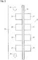
FIG. 3 in combination withFIGs. 1 and2 , respective devices orelements 11 in the power supply system are arranged in the pressurized electric chamber 9 and are thermally in contact withthermal conductors 21 for heat extraction. The term "thermally in contact" here means not only to have mere structural contact but also to have contact close enough to reduce thermal resistance. This definition is used throughout the description and the appended claims. As being well known to one skilled in the art, to establish such thermal contact, adhesives such as thermal grease are available. - One or
more partition walls 15 air-tightly separate the electric chamber 9 from theram air channel 13. Thethermal conductors 21 extend from the electric chamber 9 over thepartition walls 15 to theram air channel 13 and are thus exposed to theram air channel 13. Eachthermal conductor 21 has a tip with a structure that increases its surface area, such as a plurality of fins, thereby functioning as a heat exchanger. The tips of thethermal conductors 21 are exposed to the flow of the ram air Ar so as to radiate heat by the respective devices orelements 11 to the ram air Ar. - Each
thermal conductor 21 may be a unitary body from the interior of the electric chamber 9 to theram air channel 13 and may air-tightly penetrate thepartition walls 15. In this configuration, thepartition walls 15 may not be required to contribute to heat exchange. Eachthermal conductor 21 may be an aggregation of plural solid bodies but instead may be a single unitary body. Being a single unitary body is advantageous in light of reduction of thermal resistance. - Each
thermal conductor 21 may be of any thermally conductive substance such as aluminum, copper, silver or carbon (or graphite) to realize sufficiently low thermal resistance, or may be constituted of a heat-transfer device such as a heat pipe in part or totally. - Further, each
thermal conductor 21 may not penetrate thepartition walls 15. One body of eachthermal conductor 21 may be thermally in contact with thepartition walls 15 and another body thereof may be thermally in contact with thepartition walls 15 so that they transfers heat via thepartition walls 15. In this configuration, thepartition walls 15 constitute a part of the heat transfer path from the devices orelements 11 to theram air channel 13. To reduce thermal resistance, any thermally conductive substance such as aluminum, copper, silver or carbon (or graphite) can be applied to thepartition walls 15. - The cooling device as described above radiates heat by the respective devices or
elements 11 to the ram air Ar through the heat exchanger constituted of thethermal conductors 21 beyond thepartition walls 15 separating the pressurized cabin from theram air channel 13. While the devices orelements 11 are arranged in the pressurized cabin, heat therefrom is soon radiated from the pressurized cabin to the exterior so that the heat does not cause notable temperature rise in the respective devices or elements and the pressurized cabin, or does not affect thermal balance in the pressurized cabin. Further, as the devices orelements 11 are operated in the pressurized air, electric discharge is unlikely to occur even if they use direct current at relatively high voltage. The power supply system can use direct current at relatively high voltage and thus realize high energy efficiency. - This cooling device uses the ram air channel that an airplane normally has and does not require any other special air introduction systems. It does not limit utilization of internal space in the airplane and does not cause weight increase as well.
- Although certain embodiments have been described above, the invention is not limited to the embodiments described above. Modifications and variations of the embodiments described above will occur to those skilled in the art, in light of the above teachings.
- A cooling device that does not require an ambient air introduction system prepared particularly for cooling electronic devices is provided.
Claims (3)
- A cooling device applicable to an airplane having a pressurized cabin and a ram air channel for cooling an electronic device arranged in the pressurized cabin, comprising:a partition wall separating the pressurized cabin from the ram air channel; anda heat exchanger thermally in contact with the electronic device and exposed to the ram air channel so as to radiate heat to a ram air.
- The cooling device of claim 1, wherein the heat exchanger gets thermally in contact with both faces of the partition wall, one of the faces facing to the pressurized cabin and another of the faces facing to the ram air channel, whereby the heat exchanger and the partition wall constitute a heat transfer path for transmitting heat from the electronic device to the ram air channel.
- The cooling device of claim 1 or 2, wherein the heat exchanger further includes a heat pipe.
Applications Claiming Priority (2)
| Application Number | Priority Date | Filing Date | Title |
|---|---|---|---|
| JP2014164792 | 2014-08-13 | ||
| PCT/JP2015/072374 WO2016024521A1 (en) | 2014-08-13 | 2015-08-06 | Cooling apparatus for cooling electronic device in aircraft |
Publications (3)
| Publication Number | Publication Date |
|---|---|
| EP3130543A1 true EP3130543A1 (en) | 2017-02-15 |
| EP3130543A4 EP3130543A4 (en) | 2017-12-20 |
| EP3130543B1 EP3130543B1 (en) | 2020-10-07 |
Family
ID=55304150
Family Applications (1)
| Application Number | Title | Priority Date | Filing Date |
|---|---|---|---|
| EP15831480.7A Active EP3130543B1 (en) | 2014-08-13 | 2015-08-06 | Cooling apparatus for cooling electronic device in aircraft |
Country Status (5)
| Country | Link |
|---|---|
| US (1) | US9999164B2 (en) |
| EP (1) | EP3130543B1 (en) |
| JP (1) | JP6447630B2 (en) |
| CA (1) | CA2954750C (en) |
| WO (1) | WO2016024521A1 (en) |
Families Citing this family (2)
| Publication number | Priority date | Publication date | Assignee | Title |
|---|---|---|---|---|
| CN118104407A (en) | 2021-09-30 | 2024-05-28 | 史密斯英特康公司 | Thermal management system and method for externally mounted electronic equipment of an aircraft |
| US11697502B2 (en) * | 2021-11-17 | 2023-07-11 | Beta Air, Llc | Systems and methods for cooling a high voltage cable on an electric aircraft |
Family Cites Families (27)
| Publication number | Priority date | Publication date | Assignee | Title |
|---|---|---|---|---|
| US3752422A (en) * | 1971-06-30 | 1973-08-14 | Boeing Co | Jet augmented ram air scoop |
| US4819720A (en) * | 1984-11-09 | 1989-04-11 | Mcdonnell Douglas Corporation | Skin heat exchanger |
| JPH0725357B2 (en) | 1985-02-07 | 1995-03-22 | 三菱電機株式会社 | Streamlined containment vessel cooling system |
| JPS6461999A (en) | 1987-09-02 | 1989-03-08 | Mitsubishi Heavy Ind Ltd | Cooling device for apparatus of moving body |
| JPH01256775A (en) * | 1988-04-04 | 1989-10-13 | Mitsubishi Electric Corp | Pod cooling device |
| JP2771849B2 (en) * | 1989-06-23 | 1998-07-02 | エス・ティ・エス株式会社 | Cooling system using external surface cooler for avionics |
| US5481433A (en) * | 1994-07-01 | 1996-01-02 | Chrysler Corporation | Heat dissipation from high power semiconductors in an electrical vehicle |
| JPH1144463A (en) * | 1997-07-25 | 1999-02-16 | Shimadzu Corp | Air conditioner for aircraft |
| GB2389174B (en) * | 2002-05-01 | 2005-10-26 | Rolls Royce Plc | Cooling systems |
| JP2004029554A (en) | 2002-06-27 | 2004-01-29 | Olympus Corp | Image pickup lens unit and image pickup device |
| JP2004256051A (en) * | 2003-02-27 | 2004-09-16 | Sumitomo Precision Prod Co Ltd | Liquid cooling system for aircraft |
| JP2006042441A (en) | 2004-07-23 | 2006-02-09 | Toyota Motor Corp | COOLING SYSTEM, ITS CONTROL METHOD, AND AUTOMOBILE |
| US20100006261A1 (en) * | 2006-09-19 | 2010-01-14 | Mitsubishi Electric Corporation | Moving Body Cooling Apparatus |
| US7732953B2 (en) | 2007-06-12 | 2010-06-08 | Hamilton Sundstrand Corporation | Electric motor cooling |
| US8408281B2 (en) * | 2007-10-15 | 2013-04-02 | Lockheed Martin Corporation | System, method, and apparatus for pulsed-jet-enhanced heat exchanger |
| DE102009013159A1 (en) * | 2009-03-16 | 2010-09-23 | Airbus Operations Gmbh | Radiator for aircraft cooling system, has matrix body including coolant channels extending from surface of matrix body to another surface of matrix body so that coolant flows through matrix body |
| CN102356014B (en) * | 2009-03-24 | 2013-06-19 | 住友精密工业株式会社 | Heat sink |
| US8720828B2 (en) * | 2009-12-03 | 2014-05-13 | The Boeing Company | Extended plug cold plate |
| DE102010005902B4 (en) * | 2010-01-27 | 2017-09-14 | Airbus Operations Gmbh | Aircraft having at least one pressurized hull area and at least one non-pressurized area, and methods of venting a non-pressurized area of an aircraft |
| US8459966B2 (en) | 2010-07-19 | 2013-06-11 | Hamilton Sundstrand Corporation | Ram air fan motor cooling |
| DE102010051517A1 (en) * | 2010-11-16 | 2012-05-16 | Airbus Operations Gmbh | An aircraft exterior skin heat exchanger, aircraft cooling system, and method of operating an aircraft exterior skin heat exchanger |
| FR2971763B1 (en) * | 2011-02-22 | 2013-03-15 | Airbus Operations Sas | THERMAL EXCHANGER INCORPORATED IN A WALL OF AN AIRCRAFT |
| US8995131B2 (en) * | 2011-08-29 | 2015-03-31 | Aerovironment, Inc. | Heat transfer system for aircraft structures |
| FR2995589B1 (en) * | 2012-09-19 | 2015-07-31 | Liebherr Aerospace Toulouse Sas | BODY PANEL FOR A TRANSPORT VEHICLE COMPRISING A THERMAL EXCHANGE DEVICE AND A TRANSPORT VEHICLE COMPRISING SUCH A BODY PANEL |
| US9840967B2 (en) * | 2013-03-04 | 2017-12-12 | Rolls-Royce North American Technologies, Inc. | Ram air thermal management system |
| CN105102293B (en) * | 2013-03-26 | 2017-03-08 | 三菱电机株式会社 | Automobile-used power conversion device |
| DE102013008620A1 (en) * | 2013-05-21 | 2014-11-27 | Airbus Operations Gmbh | An aircraft cooling system and method for operating an aircraft cooling system |
-
2015
- 2015-08-06 JP JP2016542552A patent/JP6447630B2/en active Active
- 2015-08-06 EP EP15831480.7A patent/EP3130543B1/en active Active
- 2015-08-06 WO PCT/JP2015/072374 patent/WO2016024521A1/en not_active Ceased
- 2015-08-06 CA CA2954750A patent/CA2954750C/en active Active
-
2016
- 2016-10-07 US US15/288,468 patent/US9999164B2/en active Active
Also Published As
| Publication number | Publication date |
|---|---|
| CA2954750A1 (en) | 2016-02-18 |
| US20170027088A1 (en) | 2017-01-26 |
| WO2016024521A1 (en) | 2016-02-18 |
| JPWO2016024521A1 (en) | 2017-04-27 |
| EP3130543A4 (en) | 2017-12-20 |
| CA2954750C (en) | 2019-06-11 |
| US9999164B2 (en) | 2018-06-12 |
| EP3130543B1 (en) | 2020-10-07 |
| JP6447630B2 (en) | 2019-01-09 |
Similar Documents
| Publication | Publication Date | Title |
|---|---|---|
| US9885289B2 (en) | Aircraft propulsion architecture integrating an energy recovery system | |
| US8973377B2 (en) | Thermoelectric power generation using aircraft fuselage temperature differential | |
| EP2636601B1 (en) | Rotary wing aircraft propulsion system with electric power generaton | |
| US8519254B2 (en) | Device and method for generating electrical power | |
| EP3040275B1 (en) | Aircraft having a redundant and efficient bleed system | |
| US11440674B2 (en) | Aircraft energy harvesting system | |
| US9666781B2 (en) | Methods for recovering waste energy from bleed air ducts | |
| RU2595735C2 (en) | Aircraft capable of hovering | |
| Reinhardt et al. | Wide-bandgap power electronics for the More Electric Aircraft | |
| CN103061856A (en) | Thermal electrical power generation for aircraft | |
| US20240166358A1 (en) | System and method for generating electrical energy from thermal waste energy and removing thermal waste energy in an aircraft | |
| EP3412574B1 (en) | Aircraft incorporating a power unit for generatig electric, pneumatic and/or hydraulic power | |
| EP2626941A1 (en) | Fuel cell generation system | |
| US9999164B2 (en) | Cooling apparatus for cooling electronic device in aircraft | |
| US20230225210A1 (en) | Powering sensor packages in moving platforms | |
| Lui et al. | Power & Thermal Systems Integration Techniques for High Performance Jet Aircraft | |
| CN115095444A (en) | Spray pipe, aircraft engine and aircraft | |
| CN106712707A (en) | Heat-dissipation and thermoelectric generation device for solar cell panel of high-altitude aircraft |
Legal Events
| Date | Code | Title | Description |
|---|---|---|---|
| STAA | Information on the status of an ep patent application or granted ep patent |
Free format text: STATUS: THE INTERNATIONAL PUBLICATION HAS BEEN MADE |
|
| PUAI | Public reference made under article 153(3) epc to a published international application that has entered the european phase |
Free format text: ORIGINAL CODE: 0009012 |
|
| STAA | Information on the status of an ep patent application or granted ep patent |
Free format text: STATUS: REQUEST FOR EXAMINATION WAS MADE |
|
| 17P | Request for examination filed |
Effective date: 20161108 |
|
| AK | Designated contracting states |
Kind code of ref document: A1 Designated state(s): AL AT BE BG CH CY CZ DE DK EE ES FI FR GB GR HR HU IE IS IT LI LT LU LV MC MK MT NL NO PL PT RO RS SE SI SK SM TR |
|
| AX | Request for extension of the european patent |
Extension state: BA ME |
|
| DAV | Request for validation of the european patent (deleted) | ||
| DAX | Request for extension of the european patent (deleted) | ||
| A4 | Supplementary search report drawn up and despatched |
Effective date: 20171116 |
|
| RIC1 | Information provided on ipc code assigned before grant |
Ipc: H05K 7/20 20060101ALN20171110BHEP Ipc: B64D 13/08 20060101AFI20171110BHEP Ipc: B64D 13/06 20060101ALN20171110BHEP |
|
| STAA | Information on the status of an ep patent application or granted ep patent |
Free format text: STATUS: EXAMINATION IS IN PROGRESS |
|
| 17Q | First examination report despatched |
Effective date: 20181030 |
|
| REG | Reference to a national code |
Ref country code: DE Ref legal event code: R079 Ref document number: 602015060260 Country of ref document: DE Free format text: PREVIOUS MAIN CLASS: B64D0047000000 Ipc: B64D0013080000 |
|
| GRAP | Despatch of communication of intention to grant a patent |
Free format text: ORIGINAL CODE: EPIDOSNIGR1 |
|
| STAA | Information on the status of an ep patent application or granted ep patent |
Free format text: STATUS: GRANT OF PATENT IS INTENDED |
|
| RIC1 | Information provided on ipc code assigned before grant |
Ipc: B64D 13/06 20060101ALN20200220BHEP Ipc: H05K 7/20 20060101ALN20200220BHEP Ipc: B64D 13/08 20060101AFI20200220BHEP |
|
| INTG | Intention to grant announced |
Effective date: 20200320 |
|
| RIN1 | Information on inventor provided before grant (corrected) |
Inventor name: MORIOKA, NORIKO Inventor name: SEKI, NAOKI Inventor name: KIMURA, HIROYUKI Inventor name: MATSUNO, SHINSUKE |
|
| GRAS | Grant fee paid |
Free format text: ORIGINAL CODE: EPIDOSNIGR3 |
|
| GRAA | (expected) grant |
Free format text: ORIGINAL CODE: 0009210 |
|
| STAA | Information on the status of an ep patent application or granted ep patent |
Free format text: STATUS: THE PATENT HAS BEEN GRANTED |
|
| AK | Designated contracting states |
Kind code of ref document: B1 Designated state(s): AL AT BE BG CH CY CZ DE DK EE ES FI FR GB GR HR HU IE IS IT LI LT LU LV MC MK MT NL NO PL PT RO RS SE SI SK SM TR |
|
| REG | Reference to a national code |
Ref country code: GB Ref legal event code: FG4D |
|
| REG | Reference to a national code |
Ref country code: CH Ref legal event code: EP Ref country code: AT Ref legal event code: REF Ref document number: 1320935 Country of ref document: AT Kind code of ref document: T Effective date: 20201015 |
|
| REG | Reference to a national code |
Ref country code: DE Ref legal event code: R096 Ref document number: 602015060260 Country of ref document: DE |
|
| REG | Reference to a national code |
Ref country code: IE Ref legal event code: FG4D |
|
| REG | Reference to a national code |
Ref country code: NL Ref legal event code: MP Effective date: 20201007 |
|
| REG | Reference to a national code |
Ref country code: AT Ref legal event code: MK05 Ref document number: 1320935 Country of ref document: AT Kind code of ref document: T Effective date: 20201007 |
|
| PG25 | Lapsed in a contracting state [announced via postgrant information from national office to epo] |
Ref country code: GR Free format text: LAPSE BECAUSE OF FAILURE TO SUBMIT A TRANSLATION OF THE DESCRIPTION OR TO PAY THE FEE WITHIN THE PRESCRIBED TIME-LIMIT Effective date: 20210108 Ref country code: NL Free format text: LAPSE BECAUSE OF FAILURE TO SUBMIT A TRANSLATION OF THE DESCRIPTION OR TO PAY THE FEE WITHIN THE PRESCRIBED TIME-LIMIT Effective date: 20201007 Ref country code: NO Free format text: LAPSE BECAUSE OF FAILURE TO SUBMIT A TRANSLATION OF THE DESCRIPTION OR TO PAY THE FEE WITHIN THE PRESCRIBED TIME-LIMIT Effective date: 20210107 Ref country code: FI Free format text: LAPSE BECAUSE OF FAILURE TO SUBMIT A TRANSLATION OF THE DESCRIPTION OR TO PAY THE FEE WITHIN THE PRESCRIBED TIME-LIMIT Effective date: 20201007 Ref country code: RS Free format text: LAPSE BECAUSE OF FAILURE TO SUBMIT A TRANSLATION OF THE DESCRIPTION OR TO PAY THE FEE WITHIN THE PRESCRIBED TIME-LIMIT Effective date: 20201007 Ref country code: PT Free format text: LAPSE BECAUSE OF FAILURE TO SUBMIT A TRANSLATION OF THE DESCRIPTION OR TO PAY THE FEE WITHIN THE PRESCRIBED TIME-LIMIT Effective date: 20210208 |
|
| REG | Reference to a national code |
Ref country code: LT Ref legal event code: MG4D |
|
| PG25 | Lapsed in a contracting state [announced via postgrant information from national office to epo] |
Ref country code: AT Free format text: LAPSE BECAUSE OF FAILURE TO SUBMIT A TRANSLATION OF THE DESCRIPTION OR TO PAY THE FEE WITHIN THE PRESCRIBED TIME-LIMIT Effective date: 20201007 Ref country code: ES Free format text: LAPSE BECAUSE OF FAILURE TO SUBMIT A TRANSLATION OF THE DESCRIPTION OR TO PAY THE FEE WITHIN THE PRESCRIBED TIME-LIMIT Effective date: 20201007 Ref country code: BG Free format text: LAPSE BECAUSE OF FAILURE TO SUBMIT A TRANSLATION OF THE DESCRIPTION OR TO PAY THE FEE WITHIN THE PRESCRIBED TIME-LIMIT Effective date: 20210107 Ref country code: IS Free format text: LAPSE BECAUSE OF FAILURE TO SUBMIT A TRANSLATION OF THE DESCRIPTION OR TO PAY THE FEE WITHIN THE PRESCRIBED TIME-LIMIT Effective date: 20210207 Ref country code: SE Free format text: LAPSE BECAUSE OF FAILURE TO SUBMIT A TRANSLATION OF THE DESCRIPTION OR TO PAY THE FEE WITHIN THE PRESCRIBED TIME-LIMIT Effective date: 20201007 Ref country code: LV Free format text: LAPSE BECAUSE OF FAILURE TO SUBMIT A TRANSLATION OF THE DESCRIPTION OR TO PAY THE FEE WITHIN THE PRESCRIBED TIME-LIMIT Effective date: 20201007 Ref country code: PL Free format text: LAPSE BECAUSE OF FAILURE TO SUBMIT A TRANSLATION OF THE DESCRIPTION OR TO PAY THE FEE WITHIN THE PRESCRIBED TIME-LIMIT Effective date: 20201007 |
|
| PG25 | Lapsed in a contracting state [announced via postgrant information from national office to epo] |
Ref country code: HR Free format text: LAPSE BECAUSE OF FAILURE TO SUBMIT A TRANSLATION OF THE DESCRIPTION OR TO PAY THE FEE WITHIN THE PRESCRIBED TIME-LIMIT Effective date: 20201007 |
|
| REG | Reference to a national code |
Ref country code: DE Ref legal event code: R097 Ref document number: 602015060260 Country of ref document: DE |
|
| PG25 | Lapsed in a contracting state [announced via postgrant information from national office to epo] |
Ref country code: LT Free format text: LAPSE BECAUSE OF FAILURE TO SUBMIT A TRANSLATION OF THE DESCRIPTION OR TO PAY THE FEE WITHIN THE PRESCRIBED TIME-LIMIT Effective date: 20201007 Ref country code: RO Free format text: LAPSE BECAUSE OF FAILURE TO SUBMIT A TRANSLATION OF THE DESCRIPTION OR TO PAY THE FEE WITHIN THE PRESCRIBED TIME-LIMIT Effective date: 20201007 Ref country code: SK Free format text: LAPSE BECAUSE OF FAILURE TO SUBMIT A TRANSLATION OF THE DESCRIPTION OR TO PAY THE FEE WITHIN THE PRESCRIBED TIME-LIMIT Effective date: 20201007 Ref country code: SM Free format text: LAPSE BECAUSE OF FAILURE TO SUBMIT A TRANSLATION OF THE DESCRIPTION OR TO PAY THE FEE WITHIN THE PRESCRIBED TIME-LIMIT Effective date: 20201007 Ref country code: CZ Free format text: LAPSE BECAUSE OF FAILURE TO SUBMIT A TRANSLATION OF THE DESCRIPTION OR TO PAY THE FEE WITHIN THE PRESCRIBED TIME-LIMIT Effective date: 20201007 Ref country code: EE Free format text: LAPSE BECAUSE OF FAILURE TO SUBMIT A TRANSLATION OF THE DESCRIPTION OR TO PAY THE FEE WITHIN THE PRESCRIBED TIME-LIMIT Effective date: 20201007 |
|
| PLBE | No opposition filed within time limit |
Free format text: ORIGINAL CODE: 0009261 |
|
| STAA | Information on the status of an ep patent application or granted ep patent |
Free format text: STATUS: NO OPPOSITION FILED WITHIN TIME LIMIT |
|
| PG25 | Lapsed in a contracting state [announced via postgrant information from national office to epo] |
Ref country code: DK Free format text: LAPSE BECAUSE OF FAILURE TO SUBMIT A TRANSLATION OF THE DESCRIPTION OR TO PAY THE FEE WITHIN THE PRESCRIBED TIME-LIMIT Effective date: 20201007 |
|
| 26N | No opposition filed |
Effective date: 20210708 |
|
| PG25 | Lapsed in a contracting state [announced via postgrant information from national office to epo] |
Ref country code: IT Free format text: LAPSE BECAUSE OF FAILURE TO SUBMIT A TRANSLATION OF THE DESCRIPTION OR TO PAY THE FEE WITHIN THE PRESCRIBED TIME-LIMIT Effective date: 20201007 Ref country code: AL Free format text: LAPSE BECAUSE OF FAILURE TO SUBMIT A TRANSLATION OF THE DESCRIPTION OR TO PAY THE FEE WITHIN THE PRESCRIBED TIME-LIMIT Effective date: 20201007 |
|
| PG25 | Lapsed in a contracting state [announced via postgrant information from national office to epo] |
Ref country code: SI Free format text: LAPSE BECAUSE OF FAILURE TO SUBMIT A TRANSLATION OF THE DESCRIPTION OR TO PAY THE FEE WITHIN THE PRESCRIBED TIME-LIMIT Effective date: 20201007 |
|
| REG | Reference to a national code |
Ref country code: CH Ref legal event code: PL |
|
| PG25 | Lapsed in a contracting state [announced via postgrant information from national office to epo] |
Ref country code: MC Free format text: LAPSE BECAUSE OF FAILURE TO SUBMIT A TRANSLATION OF THE DESCRIPTION OR TO PAY THE FEE WITHIN THE PRESCRIBED TIME-LIMIT Effective date: 20201007 |
|
| REG | Reference to a national code |
Ref country code: BE Ref legal event code: MM Effective date: 20210831 |
|
| PG25 | Lapsed in a contracting state [announced via postgrant information from national office to epo] |
Ref country code: LI Free format text: LAPSE BECAUSE OF NON-PAYMENT OF DUE FEES Effective date: 20210831 Ref country code: CH Free format text: LAPSE BECAUSE OF NON-PAYMENT OF DUE FEES Effective date: 20210831 |
|
| PG25 | Lapsed in a contracting state [announced via postgrant information from national office to epo] |
Ref country code: IS Free format text: LAPSE BECAUSE OF FAILURE TO SUBMIT A TRANSLATION OF THE DESCRIPTION OR TO PAY THE FEE WITHIN THE PRESCRIBED TIME-LIMIT Effective date: 20210207 Ref country code: LU Free format text: LAPSE BECAUSE OF NON-PAYMENT OF DUE FEES Effective date: 20210806 |
|
| PG25 | Lapsed in a contracting state [announced via postgrant information from national office to epo] |
Ref country code: IE Free format text: LAPSE BECAUSE OF NON-PAYMENT OF DUE FEES Effective date: 20210806 Ref country code: BE Free format text: LAPSE BECAUSE OF NON-PAYMENT OF DUE FEES Effective date: 20210831 |
|
| PG25 | Lapsed in a contracting state [announced via postgrant information from national office to epo] |
Ref country code: HU Free format text: LAPSE BECAUSE OF FAILURE TO SUBMIT A TRANSLATION OF THE DESCRIPTION OR TO PAY THE FEE WITHIN THE PRESCRIBED TIME-LIMIT; INVALID AB INITIO Effective date: 20150806 |
|
| PG25 | Lapsed in a contracting state [announced via postgrant information from national office to epo] |
Ref country code: CY Free format text: LAPSE BECAUSE OF FAILURE TO SUBMIT A TRANSLATION OF THE DESCRIPTION OR TO PAY THE FEE WITHIN THE PRESCRIBED TIME-LIMIT Effective date: 20201007 |
|
| PG25 | Lapsed in a contracting state [announced via postgrant information from national office to epo] |
Ref country code: MK Free format text: LAPSE BECAUSE OF FAILURE TO SUBMIT A TRANSLATION OF THE DESCRIPTION OR TO PAY THE FEE WITHIN THE PRESCRIBED TIME-LIMIT Effective date: 20201007 |
|
| PG25 | Lapsed in a contracting state [announced via postgrant information from national office to epo] |
Ref country code: TR Free format text: LAPSE BECAUSE OF FAILURE TO SUBMIT A TRANSLATION OF THE DESCRIPTION OR TO PAY THE FEE WITHIN THE PRESCRIBED TIME-LIMIT Effective date: 20201007 |
|
| PG25 | Lapsed in a contracting state [announced via postgrant information from national office to epo] |
Ref country code: MT Free format text: LAPSE BECAUSE OF FAILURE TO SUBMIT A TRANSLATION OF THE DESCRIPTION OR TO PAY THE FEE WITHIN THE PRESCRIBED TIME-LIMIT Effective date: 20201007 |
|
| PGFP | Annual fee paid to national office [announced via postgrant information from national office to epo] |
Ref country code: DE Payment date: 20250724 Year of fee payment: 11 |
|
| PGFP | Annual fee paid to national office [announced via postgrant information from national office to epo] |
Ref country code: GB Payment date: 20250724 Year of fee payment: 11 |
|
| PGFP | Annual fee paid to national office [announced via postgrant information from national office to epo] |
Ref country code: FR Payment date: 20250723 Year of fee payment: 11 |