EP3130499A1 - Oil filler port opening and closing device - Google Patents
Oil filler port opening and closing device Download PDFInfo
- Publication number
- EP3130499A1 EP3130499A1 EP15777189.0A EP15777189A EP3130499A1 EP 3130499 A1 EP3130499 A1 EP 3130499A1 EP 15777189 A EP15777189 A EP 15777189A EP 3130499 A1 EP3130499 A1 EP 3130499A1
- Authority
- EP
- European Patent Office
- Prior art keywords
- fuel
- flap
- flap body
- closing
- filling aperture
- Prior art date
- Legal status (The legal status is an assumption and is not a legal conclusion. Google has not performed a legal analysis and makes no representation as to the accuracy of the status listed.)
- Granted
Links
Images






Classifications
-
- B—PERFORMING OPERATIONS; TRANSPORTING
- B60—VEHICLES IN GENERAL
- B60K—ARRANGEMENT OR MOUNTING OF PROPULSION UNITS OR OF TRANSMISSIONS IN VEHICLES; ARRANGEMENT OR MOUNTING OF PLURAL DIVERSE PRIME-MOVERS IN VEHICLES; AUXILIARY DRIVES FOR VEHICLES; INSTRUMENTATION OR DASHBOARDS FOR VEHICLES; ARRANGEMENTS IN CONNECTION WITH COOLING, AIR INTAKE, GAS EXHAUST OR FUEL SUPPLY OF PROPULSION UNITS IN VEHICLES
- B60K15/00—Arrangement in connection with fuel supply of combustion engines or other fuel consuming energy converters, e.g. fuel cells; Mounting or construction of fuel tanks
- B60K15/03—Fuel tanks
- B60K15/04—Tank inlets
-
- B—PERFORMING OPERATIONS; TRANSPORTING
- B60—VEHICLES IN GENERAL
- B60K—ARRANGEMENT OR MOUNTING OF PROPULSION UNITS OR OF TRANSMISSIONS IN VEHICLES; ARRANGEMENT OR MOUNTING OF PLURAL DIVERSE PRIME-MOVERS IN VEHICLES; AUXILIARY DRIVES FOR VEHICLES; INSTRUMENTATION OR DASHBOARDS FOR VEHICLES; ARRANGEMENTS IN CONNECTION WITH COOLING, AIR INTAKE, GAS EXHAUST OR FUEL SUPPLY OF PROPULSION UNITS IN VEHICLES
- B60K15/00—Arrangement in connection with fuel supply of combustion engines or other fuel consuming energy converters, e.g. fuel cells; Mounting or construction of fuel tanks
- B60K15/03—Fuel tanks
- B60K15/04—Tank inlets
- B60K15/0406—Filler caps for fuel tanks
-
- B—PERFORMING OPERATIONS; TRANSPORTING
- B67—OPENING, CLOSING OR CLEANING BOTTLES, JARS OR SIMILAR CONTAINERS; LIQUID HANDLING
- B67D—DISPENSING, DELIVERING OR TRANSFERRING LIQUIDS, NOT OTHERWISE PROVIDED FOR
- B67D7/00—Apparatus or devices for transferring liquids from bulk storage containers or reservoirs into vehicles or into portable containers, e.g. for retail sale purposes
- B67D7/06—Details or accessories
- B67D7/36—Arrangements of flow- or pressure-control valves
-
- F—MECHANICAL ENGINEERING; LIGHTING; HEATING; WEAPONS; BLASTING
- F01—MACHINES OR ENGINES IN GENERAL; ENGINE PLANTS IN GENERAL; STEAM ENGINES
- F01M—LUBRICATING OF MACHINES OR ENGINES IN GENERAL; LUBRICATING INTERNAL COMBUSTION ENGINES; CRANKCASE VENTILATING
- F01M11/00—Component parts, details or accessories, not provided for in, or of interest apart from, groups F01M1/00 - F01M9/00
- F01M11/04—Filling or draining lubricant of or from machines or engines
-
- F—MECHANICAL ENGINEERING; LIGHTING; HEATING; WEAPONS; BLASTING
- F16—ENGINEERING ELEMENTS AND UNITS; GENERAL MEASURES FOR PRODUCING AND MAINTAINING EFFECTIVE FUNCTIONING OF MACHINES OR INSTALLATIONS; THERMAL INSULATION IN GENERAL
- F16K—VALVES; TAPS; COCKS; ACTUATING-FLOATS; DEVICES FOR VENTING OR AERATING
- F16K1/00—Lift valves or globe valves, i.e. cut-off apparatus with closure members having at least a component of their opening and closing motion perpendicular to the closing faces
- F16K1/16—Lift valves or globe valves, i.e. cut-off apparatus with closure members having at least a component of their opening and closing motion perpendicular to the closing faces with pivoted closure-members
- F16K1/18—Lift valves or globe valves, i.e. cut-off apparatus with closure members having at least a component of their opening and closing motion perpendicular to the closing faces with pivoted closure-members with pivoted discs or flaps
- F16K1/20—Lift valves or globe valves, i.e. cut-off apparatus with closure members having at least a component of their opening and closing motion perpendicular to the closing faces with pivoted closure-members with pivoted discs or flaps with axis of rotation arranged externally of valve member
- F16K1/2021—Lift valves or globe valves, i.e. cut-off apparatus with closure members having at least a component of their opening and closing motion perpendicular to the closing faces with pivoted closure-members with pivoted discs or flaps with axis of rotation arranged externally of valve member with a plurality of valve members
-
- B—PERFORMING OPERATIONS; TRANSPORTING
- B60—VEHICLES IN GENERAL
- B60K—ARRANGEMENT OR MOUNTING OF PROPULSION UNITS OR OF TRANSMISSIONS IN VEHICLES; ARRANGEMENT OR MOUNTING OF PLURAL DIVERSE PRIME-MOVERS IN VEHICLES; AUXILIARY DRIVES FOR VEHICLES; INSTRUMENTATION OR DASHBOARDS FOR VEHICLES; ARRANGEMENTS IN CONNECTION WITH COOLING, AIR INTAKE, GAS EXHAUST OR FUEL SUPPLY OF PROPULSION UNITS IN VEHICLES
- B60K15/00—Arrangement in connection with fuel supply of combustion engines or other fuel consuming energy converters, e.g. fuel cells; Mounting or construction of fuel tanks
- B60K15/03—Fuel tanks
- B60K15/04—Tank inlets
- B60K15/0406—Filler caps for fuel tanks
- B60K2015/0419—Self-sealing closure caps, e.g. that don't have to be removed manually
- B60K2015/0429—Self-sealing closure caps, e.g. that don't have to be removed manually actuated by the nozzle
-
- B—PERFORMING OPERATIONS; TRANSPORTING
- B60—VEHICLES IN GENERAL
- B60K—ARRANGEMENT OR MOUNTING OF PROPULSION UNITS OR OF TRANSMISSIONS IN VEHICLES; ARRANGEMENT OR MOUNTING OF PLURAL DIVERSE PRIME-MOVERS IN VEHICLES; AUXILIARY DRIVES FOR VEHICLES; INSTRUMENTATION OR DASHBOARDS FOR VEHICLES; ARRANGEMENTS IN CONNECTION WITH COOLING, AIR INTAKE, GAS EXHAUST OR FUEL SUPPLY OF PROPULSION UNITS IN VEHICLES
- B60K15/00—Arrangement in connection with fuel supply of combustion engines or other fuel consuming energy converters, e.g. fuel cells; Mounting or construction of fuel tanks
- B60K15/03—Fuel tanks
- B60K15/04—Tank inlets
- B60K2015/0458—Details of the tank inlet
- B60K2015/0461—Details of the tank inlet comprising a filler pipe shutter, e.g. trap, door or flap for fuel inlet
-
- B—PERFORMING OPERATIONS; TRANSPORTING
- B67—OPENING, CLOSING OR CLEANING BOTTLES, JARS OR SIMILAR CONTAINERS; LIQUID HANDLING
- B67D—DISPENSING, DELIVERING OR TRANSFERRING LIQUIDS, NOT OTHERWISE PROVIDED FOR
- B67D7/00—Apparatus or devices for transferring liquids from bulk storage containers or reservoirs into vehicles or into portable containers, e.g. for retail sale purposes
- B67D7/04—Apparatus or devices for transferring liquids from bulk storage containers or reservoirs into vehicles or into portable containers, e.g. for retail sale purposes for transferring fuels, lubricants or mixed fuels and lubricants
-
- B—PERFORMING OPERATIONS; TRANSPORTING
- B67—OPENING, CLOSING OR CLEANING BOTTLES, JARS OR SIMILAR CONTAINERS; LIQUID HANDLING
- B67D—DISPENSING, DELIVERING OR TRANSFERRING LIQUIDS, NOT OTHERWISE PROVIDED FOR
- B67D7/00—Apparatus or devices for transferring liquids from bulk storage containers or reservoirs into vehicles or into portable containers, e.g. for retail sale purposes
- B67D7/06—Details or accessories
- B67D7/42—Filling nozzles
-
- F—MECHANICAL ENGINEERING; LIGHTING; HEATING; WEAPONS; BLASTING
- F01—MACHINES OR ENGINES IN GENERAL; ENGINE PLANTS IN GENERAL; STEAM ENGINES
- F01M—LUBRICATING OF MACHINES OR ENGINES IN GENERAL; LUBRICATING INTERNAL COMBUSTION ENGINES; CRANKCASE VENTILATING
- F01M11/00—Component parts, details or accessories, not provided for in, or of interest apart from, groups F01M1/00 - F01M9/00
- F01M11/04—Filling or draining lubricant of or from machines or engines
- F01M11/0408—Sump drainage devices, e.g. valves, plugs
- F01M2011/0416—Plugs
Definitions
- the present invention relates to fuel filling aperture opening and closing device which opens a fuel-filling aperture by inserting a fuel-filling nozzle to allow this insertion and automatically closes the fuel-filling aperture when the inserted fuel-filling nozzle has been pulled out.
- the opening and closing device includes a shutter-like closing device turned around a turning axis along the center axis of the fuel injection pipe and turns this closing device toward a side of a passage hole of a fuel-filling nozzle by a force applied by the fuel-filling nozzle to open the fuel-filling nozzle.
- the closing device closes the fuel-filling aperture but does not have a structure biased in a direction in which the closing device is attached firmly to the fuel-filling aperture and is not excellent in sealing property when closing the fuel-filling aperture.
- Patent Literature 1 Japanese Patent No. 4198971
- a main object to be solved by the present invention is that in this kind of a fuel-filling aperture opening/closing device, a sealing property at the time of closing a fuel-filling aperture is made more reliably and better.
- the present invention provides a fuel-filling aperture opening and closing device including a closing member which is turned to an opening position by insertion of a fuel-filling nozzle to open a fuel-filling aperture, wherein the closing member includes a pair of flap bodies and biasing means which positions each of the flap bodies in a closing position by a biasing force, and the pair of flap bodies each includes a turning assembly portion as the center of the turning and an abutment portion with respect to the other flap body and is each configured to press its front surface portion against a hole edge portion of a passage hole of the fuel-filling nozzle by the biasing force and press the abutment portion against the abutment portion of the other flap body.
- the closing member presses its front surface portion against the hole edge portion of the passage hole at the closing position, and the abutment portions of the pair of flap bodies are interlocked with a small gap, whereby a closing state of the fuel-filling aperture is maintained with a high sealing property.
- the biasing means is a coil spring which abuts at one spring end against a side of a support of the flap body and at the same time abuts at the other spring end against an inclined surface formed at a back surface portion of the flap body and facing a thickness direction of the flap body gradually increasing as it approaches the abutment portion.
- the flap body which is subjected to a biasing force of this spring to be moved back to the closing position can be subjected to a force applied in a direction in which the abutment portion of this flap body is pressed against the abutment portion of the other flap body, so that the abutment portions of the pair of flap bodies can be interlocked with a small gap at the closing position.
- a shaft body provided on one of the support and the turning assembly portion of the flap body is retained in a shaft hole provided in the other of the support and the turning assembly portion with a room, so that the flap body is turnably supported.
- the flap body includes at its back surface portion a guide surface which, when timing of moving back to the closing position due to the biasing force is changed between the pair of flap bodies, is in contact with a portion of the other flap body to guide the other flap body to the closing position.
- the flap body includes at its front surface portion a groove-shaped recess having a circular arc cross-sectional shape in a direction parallel to the center axis of the turning.
- a groove-shaped recess having a circular arc cross-sectional shape in a direction parallel to the center axis of the turning.
- the sealing property at the time of closing of the fuel-filling aperture can be made reliably and well by the pair of flap bodies.
- a fuel-filling aperture opening/closing device opens a fuel-filling aperture by inserting a fuel-filling nozzle N to allow this insertion and automatically closes the fuel-filling aperture when the inserted fuel-filling nozzle N has been pulled out.
- the above fuel-filling aperture opening/closing device turns the undermentioned closing members La and Ua to an opening position to allow an insertion of the fuel-filling nozzle N further than the fuel-filling aperture opening/closing device and thus to enable fuel filling.
- the undermentioned closing members La and Ua are moved back to a closing position to automatically close the fuel-filling aperture. Consequently, in this fuel-filling aperture opening/closing device, a screw cap of a fuel-filling aperture is not required.
- the fuel-filling aperture opening/closing device is attached to an upper end Pa of an inlet pipe P (fuel injection pipe) constituting the fuel-filling aperture (see Fig. 4 ).
- an inlet pipe P fuel injection pipe
- two types of fuel-filling aperture opening/closing devices having different functions are attached to the upper end Pa of the inlet pipe P.
- One of the two types of fuel-filling aperture opening/closing devices (hereinafter, this fuel-filling aperture opening/closing device is referred to as a lower device L) is embedded inside the upper end Pa of the inlet pipe P.
- the other fuel-filling aperture opening/closing device (hereinafter referred to as an upper device U) is fitted in the outside of the upper end Pa of the inlet pipe P from a state in which the lower device L is embedded inside the upper end Pa of the inlet pipe P.
- the closing member Ua of the upper device U is located directly above the closing member La of the lower device L.
- the lower device L is provided with a cylindrical main body Lb and the closing member La (see Fig. 7 ).
- the cylindrical main body Lb opens both an upper end and a lower end and substantially presents a cylindrical shape.
- An inner space of the cylindrical main body Lb is vertically divided by a bulkhead 12 between the upper end and the lower end.
- An outer diameter of the cylindrical main body Lb is substantially equal to an inner diameter of the upper end Pa of the inlet pipe P.
- an outer flange 13 is formed at the upper end of the cylindrical main body Lb, and an engaging projection 14 is formed on an outer surface portion of the cylindrical main body Lb.
- the upper end Pa of the inlet pipe P has an engagement hole Pb receiving the engaging projection 14 of the cylindrical main body Lb in a process for embedding the lower device L inside the upper end Pa of the inlet pipe P to a position where the outer flange 13 abuts against a terminal of the inlet pipe P, and the engagement hole Pb is engaged with the engaging projection 14 by elastic return at an embedding finish position.
- the embedding state of the lower device L with respect to the inlet pipe P is maintained by this engagement.
- the bulkhead 12 has a circular passage hole 15 allowing passage of the fuel-filling nozzle N.
- the closing member La is in pressure contact with the bulkhead 12 from below at the closing position to close the passage hole 15 and thus to maintain a closed state of the fuel-filling aperture unless the fuel-filling nozzle N is inserted (see Fig. 4 ).
- the hole edge portion of the passage hole 15 is rimmed by a protrusion 16 (see Fig. 9 ).
- a short dimensional cylindrical portion is formed on the lower surface of the bulkhead 12 by the protrusion 16.
- the closing member La is configured to bring a plate-shaped portion 101b (shown in Fig. 10 ) of the undermentioned seal member 101 into press contact with the protrusion 16 by a biasing force of the undermentioned biasing means 11 (shown in Fig. 3 ) at the closing position to close the passage hole 15 in an airtight manner.
- the protrusion 16 functions as a valve seat.
- the closing member La is provided with a flap body 10 provided with the ring-shaped seal member 101 and the biasing means 11 positioning the flap body 10 in the closing position by the biasing force.
- the flap body 10 is constituted of an outer member 102 and an inner member 103 combined through the seal member 101 (see Figs. 10 to 12 ).
- the outer member 102 is located on the terminal side of the inlet pipe P, and the inner member 103 is located on a depth side of the inlet pipe P.
- the inner member 103 substantially presents a disc shape.
- the inner member 103 has on its front surface side an inside circular wall 103a, an outside circular wall 103b surrounding the inside circular wall 103a, and a circular groove 103d surrounding the outside circular wall 103b (see Fig. 10 ).
- a circular flat surface 103e is formed between the circular groove 103d and an outer edge of the inner member 103.
- the inner member 103 has a pair of bearing portions 103f, 103f on its back surface side (see Fig. 11 ).
- the pair of bearing portions 103f, 103f each has an arm shape protruding from the back surface side of the inner member 103, and a protruding end is positioned outer side than the outer edge of the inner member 103 and provided with a shaft hole 103g.
- a pair of bearing portions 17, 17 is formed below the bulkhead 12 of the cylindrical main body Lb (see Fig. 3 ).
- the pair of bearing portions 103f, 103f of the inner member 103 is stored between the pair of bearing portions 17, 17 of the cylindrical main body Lb, and, at the same time, a shaft body Lc is inserted through the shaft holes 103g formed in the pair of bearing portions 103f, 103f, whereby the closing member La is attached to the cylindrical main body Lb so as to be turnable about the shaft body Lc.
- the outer member 102 has a size fitting into the passage hole 15 in a state in which the flap body 10 is located at the closing position, and the outer member 102 has a circular outline shape (see FIG. 11 ).
- the fuel-filling nozzle N abuts against a front surface of the outer member 102.
- the outer member 102 has a circular clipping portion 102a on its back surface side (see Fig. 10 ). Engagement claws 102b protruding outward on both sides in a diameter direction of the outer member 102 are each formed at a side portion of the outer member 102, that is, above the circular clipping portion 102a.
- the outer member 102 and the inner member 103 are integrated with each other by engaging the engagement claw 102b of the outer member 102 with an engagement hole 103c formed in the outside circular wall 103b of the inner member 103 in such a state that the circular clipping portion 102a of the outer member 102 is located directly above the circular groove 103d of the inner member 103, and, at the same time, the circular flat surface 103e of the inner member 103 is positioned outward an outer edge of the outer member 102.
- a ventilation hole 103h is formed inward the inside circular wall 103a of the inner member 103, and a compression coil spring 105 and a valve body 104 closing the ventilation hole 103h by a biasing force of the spring 105 are stored between the inner member 103 and the outer member 102.
- the valve body 104 rises against the biasing force of the spring 105 to open the ventilation hole 103h.
- the flap body 10 incorporates a relief valve.
- the seal member 101 is provided with seal portions 101a on the inner and outer peripheral sides, and the seal portions 101a are provided to insert a space S (shown in Fig. 10 ) between the inner and outer seal portions 101a, 101a through the depth side of the inlet pipe P.
- the seal member 101 is formed of rubber or plastic having rubber-like elasticity.
- one of the inner and outer seal portions 101a, 101a is the plate-shaped portion 101b brought into press contact with the protrusion 16 by the biasing force, the protrusion 16 rimming the hole edge portion of the passage hole 15 of the fuel-filling nozzle N.
- the other of the inner and outer seal portions 101a, 101a is constituted of an inside circular protrusion 101c and an outside circular protrusion 101d which are in press contact with the flap body 10.
- an outer diameter of the seal member 101 is substantially equal to an outer diameter of the inner member 103, and an inner diameter of the seal member 101 is substantially equal to the outer diameter of the outside circular wall 103b.
- the seal member 101 has the plate-shaped portion 101b on its outer peripheral side and has the inside circular protrusion 101c and the outside circular protrusion 101d on its inner peripheral side.
- the seal member 101 presents a substantially L-shaped cross-sectional shape including a portion perpendicular to an axial direction x (see Figs. 4 and 10 ) of the inlet pipe P and a portion along the axial direction x of the inlet pipe P (see Fig. 10 ).
- a part of the portion perpendicular to the axial direction x is the plate-shaped portion 101b, and the seal member 101 is provided with the inside circular protrusion 101c and the outside circular protrusion 101d at a terminal of a portion along the axial direction.
- the seal member 101 is formed such that while a circular outer flange 101f as the plate-shaped portion 101b is formed at one cylinder end of a short cylindrical body 101e, a circular groove 101g is formed at the other cylinder end of the short cylindrical body 101e.
- the outside circular protrusion 101d and the inside circular protrusion 101c are formed by the other cylinder end of the short cylindrical body 101e sectioned into inside and outside by the circular groove 103d ( Fig. 14 ).
- a length L1 (shown in Fig. 14 ) of the short cylindrical body 101e of the seal member 101 is larger than a distance L2 (shown in Fig. 10 ) between the circular clipping portion 102a of the outer member 102 and a groove bottom of the circular groove 103d of the inner member 103.
- the short cylindrical body 101e is stored in the circular groove 103d of the inner member 103, and the seal member 101 is combined with the inner member 103 so that the outer flange 13 is positioned on the circular flat surface 103e.
- the outer member 102 is combined with the inner member 103 as described above, whereby the seal member 101 is held between the inner member 103 and the outer member 102. Consequently, the plate-shaped portion 101b of the seal member 101 is positioned outward the outer member 102, and the inside circular protrusion 101c and the outside circular protrusion 101d of the seal member 101 are positioned between the inner member 103 and the outer member 102.
- the inside circular protrusion 101c of the seal member 101 is in press contact with the groove bottom of the circular groove 103d while being elastically deformed to be narrowed inward, and the outside circular protrusion 101d is in press contact with the groove bottom of the circular groove 103d while being elastically deformed to extend outward.
- the plate-shaped portion 101b is held between the protrusion 16 and the circular flat surface 103e while being bent by the protrusion 16 such that the upper side is a bent inner side ( Fig. 10 ).
- the biasing means 11 is a coil spring 11a in the illustrated example (see Fig. 3 ).
- the shaft body Lc passes through a spring wound portion 11b between the pair of bearing portions 103f, 103f of the inner member 103 to have one spring end of the coil spring 11a, held with the spring wound portion 11b, abut against the back surface side of the inner member 103, and, at the same time, abut the other spring end of the spring against the bulkhead 12, whereby the biasing force applied toward the closing position is always applied to the flap body 10.
- the inner member 103 has a communication hole 103i for inserting the space S between the inner and outer seal portions 101a, 101a through the depth side of the inlet pipe P.
- the communication hole 103i extending to a groove wall outside of the circular groove 103d of the inner member 103 (see Fig. 10 ), whereby the space S between the plate-shaped portion 101b and the outside circular protrusion 101d is in a state of being communicated with the depth side of the inlet pipe P, that is, the fuel tank side.
- the plate-shaped portion 101b which is one of the inner and outer seal portions 101a, 101a of the seal member 101 is brought into press contact with the protrusion 16 by the biasing force, and the biasing force is concentrated on a relatively narrow press-contact portion with respect to the protrusion 16; therefore, the sealing property of the plate-shaped portion 101b is maintained high.
- the protrusion 16 is not provided, if the seal member 101 is swollen by a fuel, although a seal portion where the seal member 101 is in contact with the hole edge portion of the passage hole 15 may change, the seal portion is not changed by the protrusion 16 even if the swelling or the like occurs.
- the other of the inner and outer seal portions 101a, 101a of the seal member 101 is constituted of the inside circular protrusion 101c and the outside circular protrusion 101d, not only when the depth side of the inlet pipe P is a high pressure, but also when the outside of the inlet pipe P is a high pressure, a circular protrusion located on the high pressure side in the inside circular protrusion 101c and the outside circular protrusion 101d is brought into press contact with the flap body 10 by a pressure difference, whereby the sealing property between the seal member 101 and the flap body 10 can be enhanced.
- the seal member 101 communicates the space S between the inner and outer seal portions 101a, 101a through the depth side of the inlet pipe P, and while the outside circular protrusion 101d is in press contact with the groove bottom of the circular groove 103d while being elastically deformed to extend outward, the inside circular protrusion 101c is in press contact with the groove bottom of the circular groove 103d while being elastically deformed to be narrowed inward (see Fig. 10 ). Therefore, when the depth side of the inlet pipe P is a high pressure, the outside circular protrusion 101d is brought into press contact with the flap body 10 (the groove bottom of the circular groove 103d) by this pressure to enhance the sealing property between the seal member 101 and the flap body 10.
- the plate-shaped portion 101b is held between the protrusion 16 and the circular flat surface 103e while being bent by the protrusion 16 such that the upper side is the bent inner side, and when the depth side of the inlet pipe P is a high pressure, a force F in Fig. 10 is applied to a terminal of the plate-shaped portion 101b. Consequently, in this embodiment, when the depth side of the inlet pipe P is a high pressure, the plate-shaped portion 101b of the seal member 101 is deformed in a direction in which adhesiveness with respect to the protrusion 16 rimming the hole edge portion of the passage hole 15 is enhanced.
- the upper device U is provided with a cylindrical main body Ub and the closing member Ua (see Fig. 1 ).
- the cylindrical main body Ub opens a lower end and has at its upper end an inner flange 20 having a circular shape, and an upper end opening which is a passage hole 21 of the fuel-filling nozzle N is narrowed by the inner flange 20 (see Fig. 5 ).
- the cylindrical main body Ub presents a substantially cylindrical shape.
- An inner diameter of the cylindrical main body Ub is substantially equal to an outer diameter of the upper end Pa of the inlet pipe P.
- an engagement hole 22 is formed in an outer surface portion of the cylindrical main body Ub (see Fig. 1 ).
- the inlet pipe P has at the upper end Pa an engaging projection Pc which allows the upper end Pa of the inlet pipe P to be received in the cylindrical main body Ub and is engaged with the engagement hole 22 by elastic return when the upper device U is settled in the upper end Pa of the inlet pipe P (see Fig. 7 ), and an embedding state of the upper device U with respect to the inlet pipe P is maintained by this engagement (see Fig. 1 ).
- the closing member Ua is in pressure contact with the inner flange 20 from below at the closing position to close the passage hole 21 and thus to maintain a closed state of the fuel-filling aperture unless the fuel-filling nozzle N is inserted (see Fig. 4 ).
- the closing member Ua is provided with a pair of flap bodies 18, 18 and biasing means 19 positioning each of the flap bodies 18 in the closing position by the biasing force (see Fig. 4 ).
- Each of the pair of flap bodies 18, 18 is provided with a turning assembly portion 18a as the center of the turning and an abutment portion 18b with respect to the other flap body 18 of the pair and configured to press its front surface portion against a hole edge portion 21a of the passage hole 21 of the fuel-filling nozzle N by the biasing force and press the abutment portion 18b against the abutment portion 18b of the other flap body 18 of the pair.
- the passage hole 21 presents a circular shape.
- Each of the flap bodies 18 is a plate-shaped body having a semicircular shape in plan view and provided with a semicircular arc edge portion 18c along a circular arc corresponding to 180 degrees of a virtual circle (not shown) having an outer diameter slightly larger than the hole diameter of the passage hole 21 and a linear edge portion 18d along a virtual segment (not shown) dividing the virtual circle into two parts and passing through the center of the virtual circle (see Fig. 2 ).
- the pair of flap bodies 18, 18 is configured to press each of the semicircular arc edge portions 18c against the hole edge portion 21a of the passage hole 21 from below by the biasing force and, at the same time, presses the linear edge portion 18d of one of the flap bodies 18 against the linear edge portion 18d of the other flap body 18 to close the passage hole 21 in cooperation with the other flap body 18 ( Fig. 4 ).
- Each of the flap bodies 18 has a pair of bearing portions 18e, 18e (see Fig. 6 ).
- Each of the pair of bearing portions 18e, 18e has an arm shape protruding outward from the semicircular arc edge portion 18c in a direction perpendicular to the linear edge portion 18d and has a shaft hole 18f at a protruding end.
- a pair of bearing portions 23, 23 is formed below the inner flange 20 of the cylindrical main body Ub.
- the pair of bearing portions 18e, 18e of the flap body 18 is stored between the pair of bearing portions 23, 23 of the cylindrical main body Ub, and, at the same time, a shaft body Uc is inserted through the shaft holes 18f formed in the pair of the bearing portions 18e, 18e, whereby the flap body 18 is attached to the cylindrical main body Ub so as to be turnable about the shaft body Uc.
- the axial center line of the shaft body Uc is parallel to the linear edge portion 18d.
- the biasing means 19 is a coil spring 19a which abuts at one spring end 19b against a side of a support of the flap body 18, that is, the cylindrical main body Ub and at the same time abuts at the other spring end 19c against an inclined surface 18g formed at a back surface portion of the flap body 18 and facing in a direction in which a thickness of the flap body 18 is gradually increased as it approaches the abutment portion 18b (see Figs. 4 and 5 ).
- the shaft body Uc passes through a spring wound portion 19d between the pair of bearing portions 18e, 18e of the flap body 18 to have the other spring end 19c of the coil spring 19a, held with the spring wound portion 19d, abut against the back surface side of the flap body 18, and, at the same time, have one spring end 19b of the spring 19a abut against an inner wall of the cylindrical main body Ub, whereby the biasing force applied toward the closing position is always applied to the flap body 18.
- a portion except for the semicircular arc edge portion 18c is formed into a substantially recessed shape whose bottom is a portion located on a virtual straight line y (shown in Fig. 2 ) connecting a midpoint in a length direction of the semicircular arc edge portion 18c and a midpoint in a length direction of the linear edge portion 18d.
- a portion except for the semicircular arc edge portion 18c is formed into a substantially projecting shape whose top is a portion located on the virtual straight line y connecting the midpoint in the length direction of the semicircular arc edge portion 18c and the midpoint in the length direction of the linear edge portion 18d.
- the inclined surface 18g is formed at the portion located on the virtual straight line in the back surface portion of the flap body 18.
- the inclined surface 18g starts from the semicircular arc edge portion 18c and ends at the midpoint in the length direction of the virtual straight line y (see Fig. 4 ).
- the abutment portion 18b is a vertical surface along the axial direction x of the inlet pipe P and is formed over the entire length of the linear edge portion 18d.
- the flap body 18 stores the shaft body Uc in the shaft hole 18f provided in the bearing portion 18e of the flap body 18 with room and is turnably supported by the cylindrical main body Ub as the support. Namely, an inner diameter of the shaft hole 18f is larger than an outer diameter of the shaft body Uc (see Fig. 6 ).
- the flap body 18 has at its back surface portion a guide surface 18h which, when timing of moving back to the closing position due to the biasing force is altered between the pair of flap bodies 18, 18, is in contact with a portion of the other flap body 18 to guide the other flap body 18 to the closing position (see Fig. 5 ).
- the guide surface 18h inclined in a direction in which a wall thickness of the flap body 18 is gradually increased as it is away from the abutment portion 18b is formed on the lower side of the abutment portion 18b over substantially the entire length of the linear edge portion 18d.
- a mountain-shaped rib 18i is formed between the guide surface 18h and a corner between the linear edge portion 18d and the semicircular arc edge portion 18c, and one of hypotenuses of the rib 18i is an extending guide surface 18j continuous with the guide surface 18h.
- the front surface portion of the flap body 18 is formed into a recessed shape as described above, and a groove-shaped recess 18k having a circular arc cross-sectional shape is formed at the front surface portion in a direction parallel to the center axis of the turning.
- a height of a bottom of the groove-shaped recess 18k is reduced as it approaches the abutment portion 18b.
- the end of the fuel-filling nozzle N is guided to have the direction by the groove-shaped recess 18k.
- the present invention is not limited to the above-described embodiments and includes all embodiments which can achieve the object of the present invention.
Landscapes
- Engineering & Computer Science (AREA)
- Mechanical Engineering (AREA)
- Chemical & Material Sciences (AREA)
- Combustion & Propulsion (AREA)
- General Engineering & Computer Science (AREA)
- Life Sciences & Earth Sciences (AREA)
- Sustainable Development (AREA)
- Sustainable Energy (AREA)
- Transportation (AREA)
- Cooling, Air Intake And Gas Exhaust, And Fuel Tank Arrangements In Propulsion Units (AREA)
Abstract
Description
- The present invention relates to fuel filling aperture opening and closing device which opens a fuel-filling aperture by inserting a fuel-filling nozzle to allow this insertion and automatically closes the fuel-filling aperture when the inserted fuel-filling nozzle has been pulled out.
- As an opening and closing device attached to an upper end of a fuel injection pipe, there is an opening and closing device shown in Patent Literature 1. The opening and closing device includes a shutter-like closing device turned around a turning axis along the center axis of the fuel injection pipe and turns this closing device toward a side of a passage hole of a fuel-filling nozzle by a force applied by the fuel-filling nozzle to open the fuel-filling nozzle. In the device shown in Patent Literature 1, the closing device closes the fuel-filling aperture but does not have a structure biased in a direction in which the closing device is attached firmly to the fuel-filling aperture and is not excellent in sealing property when closing the fuel-filling aperture.
- Patent Literature 1: Japanese Patent No.
4198971 - A main object to be solved by the present invention is that in this kind of a fuel-filling aperture opening/closing device, a sealing property at the time of closing a fuel-filling aperture is made more reliably and better.
- To achieve the above object, the present invention provides a fuel-filling aperture opening and closing device including a closing member which is turned to an opening position by insertion of a fuel-filling nozzle to open a fuel-filling aperture, wherein the closing member includes a pair of flap bodies and biasing means which positions each of the flap bodies in a closing position by a biasing force, and the pair of flap bodies each includes a turning assembly portion as the center of the turning and an abutment portion with respect to the other flap body and is each configured to press its front surface portion against a hole edge portion of a passage hole of the fuel-filling nozzle by the biasing force and press the abutment portion against the abutment portion of the other flap body.
- The closing member presses its front surface portion against the hole edge portion of the passage hole at the closing position, and the abutment portions of the pair of flap bodies are interlocked with a small gap, whereby a closing state of the fuel-filling aperture is maintained with a high sealing property.
- In one of preferred aspects of the present invention, the biasing means is a coil spring which abuts at one spring end against a side of a support of the flap body and at the same time abuts at the other spring end against an inclined surface formed at a back surface portion of the flap body and facing a thickness direction of the flap body gradually increasing as it approaches the abutment portion. According to this constitution, the flap body which is subjected to a biasing force of this spring to be moved back to the closing position can be subjected to a force applied in a direction in which the abutment portion of this flap body is pressed against the abutment portion of the other flap body, so that the abutment portions of the pair of flap bodies can be interlocked with a small gap at the closing position.
- Further, in one of the preferred aspects of the present invention, in the flap body, a shaft body provided on one of the support and the turning assembly portion of the flap body is retained in a shaft hole provided in the other of the support and the turning assembly portion with a room, so that the flap body is turnably supported.
- Further, in one of the preferred aspects of the present invention, the flap body includes at its back surface portion a guide surface which, when timing of moving back to the closing position due to the biasing force is changed between the pair of flap bodies, is in contact with a portion of the other flap body to guide the other flap body to the closing position.
- Further, in one of the preferred aspects of the present invention, the flap body includes at its front surface portion a groove-shaped recess having a circular arc cross-sectional shape in a direction parallel to the center axis of the turning. In such case, when the fuel-filling nozzle is not inserted in a direction in which the center axis of the fuel-filling nozzle to be inserted coincides with the center axis of the fuel-filling aperture, an end of the fuel-filling nozzle can be guided to have a direction by the groove-shaped recess.
- According to the present invention, the sealing property at the time of closing of the fuel-filling aperture can be made reliably and well by the pair of flap bodies.
-
-
Fig. 1 is a perspective view showing a state in which a fuel-filling aperture opening/closing device according to one embodiment of the present invention is attached to an upper end of an inlet pipe. -
Fig. 2 is a plan view of the state shown inFig. 1 . -
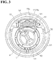
Fig. 3 is a bottom view of the state shown inFig. 1 . -
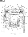
Fig. 4 is a cross-sectional view taken along a line A-A shown inFig. 2 . -
Fig. 5 is a cutaway side view of a relevant portion showing an inserted state of a fuel-filling nozzle, wherein a closing member of an upper device is located at an opening position. -
Fig. 6 is a cutaway side view showing a relevant portion of the upper device in cross section, wherein illustration of biasing means of a flap body of the upper device is omitted. -
Fig. 7 is a perspective view showing a state in which a lower device is attached to the inlet pipe, while omitting illustration of the upper device. -
Fig. 8 is a plan view of the state shown inFig. 7 . -
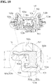
Fig. 9 is a cross-sectional view taken along a line B-B shown inFig. 8 . -
Fig. 10 is a cross-sectional view of the flap body constituting the lower device in a position of a line C-C shown inFig. 8 and shows a protrusion, which rims a passage hole, with an imaginary line. -
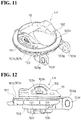
Fig. 11 is a perspective view of the flap body constituting the lower device. -
Fig. 12 is a side view of the flap body constituting the lower device. -
Fig. 13 is a plan view of the flap body constituting the lower device. -
Fig. 14 is a perspective view of a seal member constituting the lower device as viewed from the side of the inlet pipe. - Hereinafter, a typical embodiment of the present invention will be described based on
Figs. 1 to 14 . A fuel-filling aperture opening/closing device according to the embodiment opens a fuel-filling aperture by inserting a fuel-filling nozzle N to allow this insertion and automatically closes the fuel-filling aperture when the inserted fuel-filling nozzle N has been pulled out. - Namely, when the fuel-filling nozzle N of a fuel-filling gun (not shown) is inserted into a fuel-filling aperture, the above fuel-filling aperture opening/closing device turns the undermentioned closing members La and Ua to an opening position to allow an insertion of the fuel-filling nozzle N further than the fuel-filling aperture opening/closing device and thus to enable fuel filling. When the inserted fuel-filling nozzle N has been pulled out, the undermentioned closing members La and Ua are moved back to a closing position to automatically close the fuel-filling aperture. Consequently, in this fuel-filling aperture opening/closing device, a screw cap of a fuel-filling aperture is not required.
- In the illustrated example, the fuel-filling aperture opening/closing device is attached to an upper end Pa of an inlet pipe P (fuel injection pipe) constituting the fuel-filling aperture (see
Fig. 4 ). In the illustrated example, two types of fuel-filling aperture opening/closing devices having different functions are attached to the upper end Pa of the inlet pipe P. One of the two types of fuel-filling aperture opening/closing devices (hereinafter, this fuel-filling aperture opening/closing device is referred to as a lower device L) is embedded inside the upper end Pa of the inlet pipe P. The other fuel-filling aperture opening/closing device (hereinafter referred to as an upper device U) is fitted in the outside of the upper end Pa of the inlet pipe P from a state in which the lower device L is embedded inside the upper end Pa of the inlet pipe P. According to this constitution, the closing member Ua of the upper device U is located directly above the closing member La of the lower device L. When the operation of inserting the fuel-filling nozzle N is performed, the fuel-filling nozzle N abuts against the closing member Ua of the upper device U to turn the closing member Ua to the opening position and thus to enter inside of the fuel-filling aperture. Subsequently, the fuel-filling nozzle N abuts against the closing member La of the lower device L to turn the closing member La to the opening position and thus to completely open the fuel-filling aperture. - The lower device L is provided with a cylindrical main body Lb and the closing member La (see
Fig. 7 ). The cylindrical main body Lb opens both an upper end and a lower end and substantially presents a cylindrical shape. An inner space of the cylindrical main body Lb is vertically divided by abulkhead 12 between the upper end and the lower end. An outer diameter of the cylindrical main body Lb is substantially equal to an inner diameter of the upper end Pa of the inlet pipe P. In the illustrated example, anouter flange 13 is formed at the upper end of the cylindrical main body Lb, and anengaging projection 14 is formed on an outer surface portion of the cylindrical main body Lb. The upper end Pa of the inlet pipe P has an engagement hole Pb receiving theengaging projection 14 of the cylindrical main body Lb in a process for embedding the lower device L inside the upper end Pa of the inlet pipe P to a position where theouter flange 13 abuts against a terminal of the inlet pipe P, and the engagement hole Pb is engaged with theengaging projection 14 by elastic return at an embedding finish position. The embedding state of the lower device L with respect to the inlet pipe P is maintained by this engagement. Thebulkhead 12 has acircular passage hole 15 allowing passage of the fuel-filling nozzle N. The closing member La is in pressure contact with thebulkhead 12 from below at the closing position to close thepassage hole 15 and thus to maintain a closed state of the fuel-filling aperture unless the fuel-filling nozzle N is inserted (seeFig. 4 ). - On the lower surface side of the
bulkhead 12, the hole edge portion of thepassage hole 15 is rimmed by a protrusion 16 (seeFig. 9 ). Namely, a short dimensional cylindrical portion is formed on the lower surface of thebulkhead 12 by theprotrusion 16. The closing member La is configured to bring a plate-shaped portion 101b (shown inFig. 10 ) of theundermentioned seal member 101 into press contact with theprotrusion 16 by a biasing force of the undermentioned biasing means 11 (shown inFig. 3 ) at the closing position to close thepassage hole 15 in an airtight manner. Namely, in this embodiment, theprotrusion 16 functions as a valve seat. - On the other hand, the closing member La is provided with a
flap body 10 provided with the ring-shaped seal member 101 and the biasing means 11 positioning theflap body 10 in the closing position by the biasing force. - The
flap body 10 is constituted of anouter member 102 and aninner member 103 combined through the seal member 101 (seeFigs. 10 to 12 ). Theouter member 102 is located on the terminal side of the inlet pipe P, and theinner member 103 is located on a depth side of the inlet pipe P. - The
inner member 103 substantially presents a disc shape. Theinner member 103 has on its front surface side an insidecircular wall 103a, an outsidecircular wall 103b surrounding the insidecircular wall 103a, and acircular groove 103d surrounding the outsidecircular wall 103b (seeFig. 10 ). A circularflat surface 103e is formed between thecircular groove 103d and an outer edge of theinner member 103. - On the other hand, the
inner member 103 has a pair of bearingportions Fig. 11 ). The pair of bearingportions inner member 103, and a protruding end is positioned outer side than the outer edge of theinner member 103 and provided with ashaft hole 103g. In the illustrated example, a pair of bearingportions bulkhead 12 of the cylindrical main body Lb (seeFig. 3 ). In the illustrated example, the pair of bearingportions inner member 103 is stored between the pair of bearingportions shaft holes 103g formed in the pair of bearingportions - The
outer member 102 has a size fitting into thepassage hole 15 in a state in which theflap body 10 is located at the closing position, and theouter member 102 has a circular outline shape (seeFIG. 11 ). The fuel-filling nozzle N abuts against a front surface of theouter member 102. Theouter member 102 has acircular clipping portion 102a on its back surface side (seeFig. 10 ).Engagement claws 102b protruding outward on both sides in a diameter direction of theouter member 102 are each formed at a side portion of theouter member 102, that is, above thecircular clipping portion 102a. - In the illustrated example, the
outer member 102 and theinner member 103 are integrated with each other by engaging theengagement claw 102b of theouter member 102 with anengagement hole 103c formed in the outsidecircular wall 103b of theinner member 103 in such a state that thecircular clipping portion 102a of theouter member 102 is located directly above thecircular groove 103d of theinner member 103, and, at the same time, the circularflat surface 103e of theinner member 103 is positioned outward an outer edge of theouter member 102. - In the illustrated example, a
ventilation hole 103h is formed inward the insidecircular wall 103a of theinner member 103, and acompression coil spring 105 and avalve body 104 closing theventilation hole 103h by a biasing force of thespring 105 are stored between theinner member 103 and theouter member 102. When a side of a fuel tank becomes a high pressure with a predetermined value or above, thevalve body 104 rises against the biasing force of thespring 105 to open theventilation hole 103h. Namely, in the illustrated example, theflap body 10 incorporates a relief valve. - On the other hand, the
seal member 101 is provided withseal portions 101a on the inner and outer peripheral sides, and theseal portions 101a are provided to insert a space S (shown inFig. 10 ) between the inner andouter seal portions seal member 101 is formed of rubber or plastic having rubber-like elasticity. - In the
seal member 101, one of the inner andouter seal portions portion 101b brought into press contact with theprotrusion 16 by the biasing force, theprotrusion 16 rimming the hole edge portion of thepassage hole 15 of the fuel-filling nozzle N. The other of the inner andouter seal portions circular protrusion 101c and an outsidecircular protrusion 101d which are in press contact with theflap body 10. - In this embodiment, an outer diameter of the
seal member 101 is substantially equal to an outer diameter of theinner member 103, and an inner diameter of theseal member 101 is substantially equal to the outer diameter of the outsidecircular wall 103b. Further, in this embodiment, theseal member 101 has the plate-shapedportion 101b on its outer peripheral side and has the insidecircular protrusion 101c and the outsidecircular protrusion 101d on its inner peripheral side. - More specifically, the
seal member 101 presents a substantially L-shaped cross-sectional shape including a portion perpendicular to an axial direction x (seeFigs. 4 and10 ) of the inlet pipe P and a portion along the axial direction x of the inlet pipe P (seeFig. 10 ). In theseal member 101, a part of the portion perpendicular to the axial direction x is the plate-shapedportion 101b, and theseal member 101 is provided with the insidecircular protrusion 101c and the outsidecircular protrusion 101d at a terminal of a portion along the axial direction. - In the illustrated example, the
seal member 101 is formed such that while a circularouter flange 101f as the plate-shapedportion 101b is formed at one cylinder end of a shortcylindrical body 101e, acircular groove 101g is formed at the other cylinder end of the shortcylindrical body 101e. The outsidecircular protrusion 101d and the insidecircular protrusion 101c are formed by the other cylinder end of the shortcylindrical body 101e sectioned into inside and outside by thecircular groove 103d (Fig. 14 ). - A length L1 (shown in
Fig. 14 ) of the shortcylindrical body 101e of theseal member 101 is larger than a distance L2 (shown inFig. 10 ) between thecircular clipping portion 102a of theouter member 102 and a groove bottom of thecircular groove 103d of theinner member 103. - In this embodiment, the short
cylindrical body 101e is stored in thecircular groove 103d of theinner member 103, and theseal member 101 is combined with theinner member 103 so that theouter flange 13 is positioned on the circularflat surface 103e. From this state, theouter member 102 is combined with theinner member 103 as described above, whereby theseal member 101 is held between theinner member 103 and theouter member 102. Consequently, the plate-shapedportion 101b of theseal member 101 is positioned outward theouter member 102, and the insidecircular protrusion 101c and the outsidecircular protrusion 101d of theseal member 101 are positioned between theinner member 103 and theouter member 102. - The inside
circular protrusion 101c of theseal member 101 is in press contact with the groove bottom of thecircular groove 103d while being elastically deformed to be narrowed inward, and the outsidecircular protrusion 101d is in press contact with the groove bottom of thecircular groove 103d while being elastically deformed to extend outward. The plate-shapedportion 101b is held between theprotrusion 16 and the circularflat surface 103e while being bent by theprotrusion 16 such that the upper side is a bent inner side (Fig. 10 ). - The biasing means 11 is a coil spring 11a in the illustrated example (see
Fig. 3 ). In the illustrated example, the shaft body Lc passes through a spring wound portion 11b between the pair of bearingportions inner member 103 to have one spring end of the coil spring 11a, held with the spring wound portion 11b, abut against the back surface side of theinner member 103, and, at the same time, abut the other spring end of the spring against thebulkhead 12, whereby the biasing force applied toward the closing position is always applied to theflap body 10. - Further, in this embodiment, the
inner member 103 has acommunication hole 103i for inserting the space S between the inner andouter seal portions communication hole 103i extending to a groove wall outside of thecircular groove 103d of the inner member 103 (seeFig. 10 ), whereby the space S between the plate-shapedportion 101b and the outsidecircular protrusion 101d is in a state of being communicated with the depth side of the inlet pipe P, that is, the fuel tank side. - When the
flap body 10 constituting the closing member La is at the closing position, the plate-shapedportion 101b which is one of the inner andouter seal portions seal member 101 is brought into press contact with theprotrusion 16 by the biasing force, and the biasing force is concentrated on a relatively narrow press-contact portion with respect to theprotrusion 16; therefore, the sealing property of the plate-shapedportion 101b is maintained high. In a case where theprotrusion 16 is not provided, if theseal member 101 is swollen by a fuel, although a seal portion where theseal member 101 is in contact with the hole edge portion of thepassage hole 15 may change, the seal portion is not changed by theprotrusion 16 even if the swelling or the like occurs. - Since the other of the inner and
outer seal portions seal member 101 is constituted of the insidecircular protrusion 101c and the outsidecircular protrusion 101d, not only when the depth side of the inlet pipe P is a high pressure, but also when the outside of the inlet pipe P is a high pressure, a circular protrusion located on the high pressure side in the insidecircular protrusion 101c and the outsidecircular protrusion 101d is brought into press contact with theflap body 10 by a pressure difference, whereby the sealing property between theseal member 101 and theflap body 10 can be enhanced. - In the illustrated example, the
seal member 101 communicates the space S between the inner andouter seal portions circular protrusion 101d is in press contact with the groove bottom of thecircular groove 103d while being elastically deformed to extend outward, the insidecircular protrusion 101c is in press contact with the groove bottom of thecircular groove 103d while being elastically deformed to be narrowed inward (seeFig. 10 ). Therefore, when the depth side of the inlet pipe P is a high pressure, the outsidecircular protrusion 101d is brought into press contact with the flap body 10 (the groove bottom of thecircular groove 103d) by this pressure to enhance the sealing property between theseal member 101 and theflap body 10. On the other hand, when the outside of the inlet pipe P is a high pressure, the insidecircular protrusion 101c is brought into press contact with the flap body 10 (the groove bottom of thecircular groove 103d) by this pressure to enhance the sealing property between theseal member 101 and theflap body 10. - In this embodiment, the plate-shaped
portion 101b is held between theprotrusion 16 and the circularflat surface 103e while being bent by theprotrusion 16 such that the upper side is the bent inner side, and when the depth side of the inlet pipe P is a high pressure, a force F inFig. 10 is applied to a terminal of the plate-shapedportion 101b. Consequently, in this embodiment, when the depth side of the inlet pipe P is a high pressure, the plate-shapedportion 101b of theseal member 101 is deformed in a direction in which adhesiveness with respect to theprotrusion 16 rimming the hole edge portion of thepassage hole 15 is enhanced. - The upper device U is provided with a cylindrical main body Ub and the closing member Ua (see
Fig. 1 ). The cylindrical main body Ub opens a lower end and has at its upper end aninner flange 20 having a circular shape, and an upper end opening which is apassage hole 21 of the fuel-filling nozzle N is narrowed by the inner flange 20 (seeFig. 5 ). Namely, the cylindrical main body Ub presents a substantially cylindrical shape. An inner diameter of the cylindrical main body Ub is substantially equal to an outer diameter of the upper end Pa of the inlet pipe P. In the illustrated example, anengagement hole 22 is formed in an outer surface portion of the cylindrical main body Ub (seeFig. 1 ). The inlet pipe P has at the upper end Pa an engaging projection Pc which allows the upper end Pa of the inlet pipe P to be received in the cylindrical main body Ub and is engaged with theengagement hole 22 by elastic return when the upper device U is settled in the upper end Pa of the inlet pipe P (seeFig. 7 ), and an embedding state of the upper device U with respect to the inlet pipe P is maintained by this engagement (seeFig. 1 ). The closing member Ua is in pressure contact with theinner flange 20 from below at the closing position to close thepassage hole 21 and thus to maintain a closed state of the fuel-filling aperture unless the fuel-filling nozzle N is inserted (seeFig. 4 ). - On the other hand, the closing member Ua is provided with a pair of
flap bodies flap bodies 18 in the closing position by the biasing force (seeFig. 4 ). - Each of the pair of
flap bodies assembly portion 18a as the center of the turning and anabutment portion 18b with respect to theother flap body 18 of the pair and configured to press its front surface portion against ahole edge portion 21a of thepassage hole 21 of the fuel-filling nozzle N by the biasing force and press theabutment portion 18b against theabutment portion 18b of theother flap body 18 of the pair. - In the illustrated example, the
passage hole 21 presents a circular shape. Each of theflap bodies 18 is a plate-shaped body having a semicircular shape in plan view and provided with a semicirculararc edge portion 18c along a circular arc corresponding to 180 degrees of a virtual circle (not shown) having an outer diameter slightly larger than the hole diameter of thepassage hole 21 and alinear edge portion 18d along a virtual segment (not shown) dividing the virtual circle into two parts and passing through the center of the virtual circle (seeFig. 2 ). The pair offlap bodies arc edge portions 18c against thehole edge portion 21a of thepassage hole 21 from below by the biasing force and, at the same time, presses thelinear edge portion 18d of one of theflap bodies 18 against thelinear edge portion 18d of theother flap body 18 to close thepassage hole 21 in cooperation with the other flap body 18 (Fig. 4 ). - Each of the
flap bodies 18 has a pair of bearingportions Fig. 6 ). Each of the pair of bearingportions arc edge portion 18c in a direction perpendicular to thelinear edge portion 18d and has ashaft hole 18f at a protruding end. In the illustrated example, a pair of bearingportions inner flange 20 of the cylindrical main body Ub. In the illustrated example, the pair of bearingportions flap body 18 is stored between the pair of bearingportions portions flap body 18 is attached to the cylindrical main body Ub so as to be turnable about the shaft body Uc. The axial center line of the shaft body Uc is parallel to thelinear edge portion 18d. - On the other hand, the biasing means 19 is a coil spring 19a which abuts at one
spring end 19b against a side of a support of theflap body 18, that is, the cylindrical main body Ub and at the same time abuts at theother spring end 19c against an inclined surface 18g formed at a back surface portion of theflap body 18 and facing in a direction in which a thickness of theflap body 18 is gradually increased as it approaches theabutment portion 18b (seeFigs. 4 and5 ). In the illustrated example, the shaft body Uc passes through aspring wound portion 19d between the pair of bearingportions flap body 18 to have theother spring end 19c of the coil spring 19a, held with thespring wound portion 19d, abut against the back surface side of theflap body 18, and, at the same time, have onespring end 19b of the spring 19a abut against an inner wall of the cylindrical main body Ub, whereby the biasing force applied toward the closing position is always applied to theflap body 18. - In this embodiment, in the front surface portion of the
flap body 18, a portion except for the semicirculararc edge portion 18c is formed into a substantially recessed shape whose bottom is a portion located on a virtual straight line y (shown inFig. 2 ) connecting a midpoint in a length direction of the semicirculararc edge portion 18c and a midpoint in a length direction of thelinear edge portion 18d. In response to the shape of the front surface portion, in the back surface portion of theflap body 18, a portion except for the semicirculararc edge portion 18c is formed into a substantially projecting shape whose top is a portion located on the virtual straight line y connecting the midpoint in the length direction of the semicirculararc edge portion 18c and the midpoint in the length direction of thelinear edge portion 18d. In the illustrated example, the inclined surface 18g is formed at the portion located on the virtual straight line in the back surface portion of theflap body 18. - In the illustrated example, the inclined surface 18g starts from the semicircular
arc edge portion 18c and ends at the midpoint in the length direction of the virtual straight line y (seeFig. 4 ). Theabutment portion 18b is a vertical surface along the axial direction x of the inlet pipe P and is formed over the entire length of thelinear edge portion 18d. - The
flap body 18 stores the shaft body Uc in theshaft hole 18f provided in the bearingportion 18e of theflap body 18 with room and is turnably supported by the cylindrical main body Ub as the support. Namely, an inner diameter of theshaft hole 18f is larger than an outer diameter of the shaft body Uc (seeFig. 6 ). - Since the
other spring end 19c of the coil spring 19a abuts against the inclined surface 18g, a force applied in a direction in which theabutment portion 18b is pressed against theabutment portion 18b of theother flap body 18 of the pair is applied to theflap body 18 subjected to the biasing force of the spring 19a to be moved back to the closing position. Consequently, in this embodiment, theabutment portions 18b of the pair offlap bodies Fig. 4 ). - In this embodiment, the
flap body 18 has at its back surface portion aguide surface 18h which, when timing of moving back to the closing position due to the biasing force is altered between the pair offlap bodies other flap body 18 to guide theother flap body 18 to the closing position (seeFig. 5 ). In the illustrated example, theguide surface 18h inclined in a direction in which a wall thickness of theflap body 18 is gradually increased as it is away from theabutment portion 18b is formed on the lower side of theabutment portion 18b over substantially the entire length of thelinear edge portion 18d. In the illustrated example, a mountain-shapedrib 18i is formed between theguide surface 18h and a corner between thelinear edge portion 18d and the semicirculararc edge portion 18c, and one of hypotenuses of therib 18i is an extendingguide surface 18j continuous with theguide surface 18h. - In this embodiment, the front surface portion of the
flap body 18 is formed into a recessed shape as described above, and a groove-shapedrecess 18k having a circular arc cross-sectional shape is formed at the front surface portion in a direction parallel to the center axis of the turning. In the illustrated example, a height of a bottom of the groove-shapedrecess 18k is reduced as it approaches theabutment portion 18b. According to this constitution, in this embodiment, when the fuel-filling nozzle N is not inserted in a direction in which the center axis of the fuel-filling nozzle N to be inserted coincides with the center axis of the fuel-filling aperture, that is, the center axis of the inlet pipe P, the end of the fuel-filling nozzle N is guided to have the direction by the groove-shapedrecess 18k. - Incidentally, obviously, the present invention is not limited to the above-described embodiments and includes all embodiments which can achieve the object of the present invention.
-
- N
- fuel-filling nozzle
- 18
- flap body
- 18a
- turning assembly portion
- 18b
- abutment portion
- 19
- biasing means
- 21
- passage hole
- 21a
- hole edge portion
- Incidentally, all contents of the specification, claims, drawings, and abstract of Japanese Patent Application No.
2014-082155 filed on April 11, 2014
Claims (5)
- A fuel-filling aperture opening and closing device comprising:a closing member which is turned to an opening position by insertion of a fuel-filling nozzle to open a fuel-filling aperture,wherein the closing member comprises a pair of flap bodies and a biasing device which positions each of the flap bodies in a closing position by a biasing force, andthe pair of flap bodies each comprises a turning assembly portion as a center of turning, and an abutment portion with respect to another flap body, and is each configured to press a front surface portion thereof against a hole edge portion of a passage hole of the fuel-filling nozzle by the biasing force and press the abutment portion against the abutment portion of the another flap body.
- The fuel-filling aperture opening and closing device according to claim 1, wherein the biasing device is a coil spring abutting at one spring end against a side of a support of the flap body, and abutting at another spring end against an inclined surface formed at a back surface portion of the flap body and facing a thickness direction of the flap body gradually increasing as it approaches the abutment portion.
- The fuel-filling aperture opening and closing device according to claim 2, wherein in the flap body, a shaft body provided on one of the support and the turning assembly portion of the flap body is retained in a shaft hole provided in another of the support and the turning assembly portion to store the shaft body with a room so that the flap body is turnably supported by the support.
- The fuel-filling aperture opening and closing device according to any one of claims 1 to 3, wherein the flap body includes at a back surface portion thereof a guide surface which, when timing of moving back to the closing position due to the biasing force is changed between the pair of flap bodies, is in contact with a portion of the another flap body to guide the another flap body to the closing position.
- The fuel-filling aperture opening and closing device according to any one of claims 1 to 4, wherein the flap body includes at a front surface portion thereof a groove-shaped recess having a circular arc cross-sectional shape in a direction parallel to the center axis of turning.
Applications Claiming Priority (2)
| Application Number | Priority Date | Filing Date | Title |
|---|---|---|---|
| JP2014082155A JP6203105B2 (en) | 2014-04-11 | 2014-04-11 | Oil filler opening and closing device |
| PCT/JP2015/060751 WO2015156253A1 (en) | 2014-04-11 | 2015-04-06 | Oil filler port opening and closing device |
Publications (3)
| Publication Number | Publication Date |
|---|---|
| EP3130499A1 true EP3130499A1 (en) | 2017-02-15 |
| EP3130499A4 EP3130499A4 (en) | 2017-12-27 |
| EP3130499B1 EP3130499B1 (en) | 2020-06-24 |
Family
ID=54287829
Family Applications (1)
| Application Number | Title | Priority Date | Filing Date |
|---|---|---|---|
| EP15777189.0A Active EP3130499B1 (en) | 2014-04-11 | 2015-04-06 | Oil filler port opening and closing device |
Country Status (6)
| Country | Link |
|---|---|
| US (1) | US10000116B2 (en) |
| EP (1) | EP3130499B1 (en) |
| JP (1) | JP6203105B2 (en) |
| KR (1) | KR101638737B1 (en) |
| CN (1) | CN106414138B (en) |
| WO (1) | WO2015156253A1 (en) |
Families Citing this family (7)
| Publication number | Priority date | Publication date | Assignee | Title |
|---|---|---|---|---|
| US10000117B2 (en) | 2012-02-17 | 2018-06-19 | Stant Usa Corp. | Filler neck closure assembly |
| JP6419054B2 (en) * | 2015-10-09 | 2018-11-07 | 株式会社ニフコ | Filling port device |
| JP6556014B2 (en) * | 2015-10-09 | 2019-08-07 | 株式会社ニフコ | Filling port device |
| USD852444S1 (en) | 2016-08-16 | 2019-06-25 | Unger Marketing International, Llc | Bottle |
| USD867705S1 (en) | 2017-09-11 | 2019-11-19 | Unger Marketing International, Llc | Bottle |
| IT201900017525A1 (en) * | 2019-09-30 | 2021-03-30 | Italdesign Giugiaro Spa | Locking system for vehicle fuel system |
| CN111547669B (en) * | 2020-05-18 | 2024-11-08 | 中山市品物信息技术有限公司 | A refueling robot for a gas station and a control method for automatic refueling |
Family Cites Families (16)
| Publication number | Priority date | Publication date | Assignee | Title |
|---|---|---|---|---|
| US2145758A (en) * | 1937-02-09 | 1939-01-31 | Roy S Fellows | Tank closure |
| JPH04198971A (en) | 1990-11-28 | 1992-07-20 | Mita Ind Co Ltd | Developing device |
| FR2713156B1 (en) * | 1993-12-06 | 1996-03-08 | Peugeot | Arrangement for filling a motor vehicle fuel tank. |
| DE19543034A1 (en) * | 1995-11-07 | 1997-05-15 | Peter Dr Ing Loeffler | Device for automatic filling of vehicle fuel tank at filling station |
| US5730194A (en) * | 1996-03-21 | 1998-03-24 | Stant Manufacturing Inc. | Capless filler neck closure system |
| DE19709415C2 (en) * | 1997-03-07 | 1999-04-01 | Daimler Benz Ag | Closure for a filler neck of a motor vehicle tank |
| US6539990B1 (en) | 2001-11-20 | 2003-04-01 | Illinois Tool Works Inc. | Capless refueling assembly |
| DE10350471A1 (en) * | 2003-10-29 | 2005-06-09 | Alfred Engelmann Holding Gmbh | Closing device for filler neck in motor vehicles |
| JP4617779B2 (en) * | 2003-11-25 | 2011-01-26 | 豊田合成株式会社 | Cap device |
| US20080087354A1 (en) | 2006-10-16 | 2008-04-17 | Cisternino Franco A | Capless refueling system |
| JPWO2011074593A1 (en) * | 2009-12-17 | 2013-04-25 | 本田技研工業株式会社 | Vehicle fuel supply pipe device |
| US8539993B2 (en) * | 2010-03-31 | 2013-09-24 | Toyoda Gosei Co., Ltd. | Fuel tank opening and closing device |
| JP5459238B2 (en) * | 2011-01-31 | 2014-04-02 | 豊田合成株式会社 | Fuel tank opening and closing device |
| US11167637B2 (en) * | 2012-04-12 | 2021-11-09 | Toyota Jidosha Kabushiki Kaisha | Fuel filler structure for fuel tank |
| US9701194B2 (en) * | 2013-05-10 | 2017-07-11 | Stant Usa Corp. | Fuel-dispensing nozzle inhibitor |
| JP6184842B2 (en) * | 2013-11-15 | 2017-08-23 | 八千代工業株式会社 | Oil filler opening / closing structure |
-
2014
- 2014-04-11 JP JP2014082155A patent/JP6203105B2/en active Active
-
2015
- 2015-04-06 US US15/303,423 patent/US10000116B2/en active Active
- 2015-04-06 CN CN201580028261.7A patent/CN106414138B/en active Active
- 2015-04-06 WO PCT/JP2015/060751 patent/WO2015156253A1/en not_active Ceased
- 2015-04-06 EP EP15777189.0A patent/EP3130499B1/en active Active
- 2015-04-06 KR KR1020150048424A patent/KR101638737B1/en not_active Expired - Fee Related
Also Published As
| Publication number | Publication date |
|---|---|
| WO2015156253A1 (en) | 2015-10-15 |
| CN106414138A (en) | 2017-02-15 |
| US20170028841A1 (en) | 2017-02-02 |
| JP2015202744A (en) | 2015-11-16 |
| CN106414138B (en) | 2018-11-30 |
| EP3130499A4 (en) | 2017-12-27 |
| JP6203105B2 (en) | 2017-09-27 |
| EP3130499B1 (en) | 2020-06-24 |
| KR20150118030A (en) | 2015-10-21 |
| US10000116B2 (en) | 2018-06-19 |
| KR101638737B1 (en) | 2016-07-11 |
Similar Documents
| Publication | Publication Date | Title |
|---|---|---|
| EP3130499B1 (en) | Oil filler port opening and closing device | |
| CN104203624B (en) | The opening and closing device of fuel tank | |
| JP6200097B2 (en) | Valve case mounting structure | |
| US10913349B2 (en) | Fuel filler port device | |
| EP3130498B1 (en) | Oil filler port opening and closing device | |
| KR101827688B1 (en) | Fuel tank check valve | |
| US8087434B2 (en) | Filler neck for the fuel tank of a vehicle | |
| KR20150020091A (en) | Wall feed-through element for a fluid line and wall feed-through | |
| US10759271B2 (en) | Fuel filling device | |
| US20150240946A1 (en) | Method for shutting an opening in a body, in particular in a door actuator | |
| US10500948B2 (en) | Fuel filling device | |
| EP3015304A1 (en) | Fuel tank filler structure | |
| US20050092959A1 (en) | Slide valve | |
| US20200001705A1 (en) | Sleeve member for filler pipe and fuel supply portion forming device | |
| JP2007331518A (en) | Fuel feed pipe | |
| JP5988675B2 (en) | valve | |
| JP6494456B2 (en) | Governor | |
| JP2014051187A (en) | Fuel supply device |
Legal Events
| Date | Code | Title | Description |
|---|---|---|---|
| STAA | Information on the status of an ep patent application or granted ep patent |
Free format text: STATUS: THE INTERNATIONAL PUBLICATION HAS BEEN MADE |
|
| PUAI | Public reference made under article 153(3) epc to a published international application that has entered the european phase |
Free format text: ORIGINAL CODE: 0009012 |
|
| STAA | Information on the status of an ep patent application or granted ep patent |
Free format text: STATUS: REQUEST FOR EXAMINATION WAS MADE |
|
| 17P | Request for examination filed |
Effective date: 20161025 |
|
| AK | Designated contracting states |
Kind code of ref document: A1 Designated state(s): AL AT BE BG CH CY CZ DE DK EE ES FI FR GB GR HR HU IE IS IT LI LT LU LV MC MK MT NL NO PL PT RO RS SE SI SK SM TR |
|
| AX | Request for extension of the european patent |
Extension state: BA ME |
|
| DAV | Request for validation of the european patent (deleted) | ||
| DAX | Request for extension of the european patent (deleted) | ||
| A4 | Supplementary search report drawn up and despatched |
Effective date: 20171124 |
|
| RIC1 | Information provided on ipc code assigned before grant |
Ipc: F02M 37/00 20060101ALI20171120BHEP Ipc: B60K 15/05 20060101AFI20171120BHEP Ipc: B60K 15/04 20060101ALI20171120BHEP |
|
| STAA | Information on the status of an ep patent application or granted ep patent |
Free format text: STATUS: EXAMINATION IS IN PROGRESS |
|
| 17Q | First examination report despatched |
Effective date: 20190411 |
|
| GRAP | Despatch of communication of intention to grant a patent |
Free format text: ORIGINAL CODE: EPIDOSNIGR1 |
|
| STAA | Information on the status of an ep patent application or granted ep patent |
Free format text: STATUS: GRANT OF PATENT IS INTENDED |
|
| INTG | Intention to grant announced |
Effective date: 20200325 |
|
| GRAS | Grant fee paid |
Free format text: ORIGINAL CODE: EPIDOSNIGR3 |
|
| GRAA | (expected) grant |
Free format text: ORIGINAL CODE: 0009210 |
|
| STAA | Information on the status of an ep patent application or granted ep patent |
Free format text: STATUS: THE PATENT HAS BEEN GRANTED |
|
| AK | Designated contracting states |
Kind code of ref document: B1 Designated state(s): AL AT BE BG CH CY CZ DE DK EE ES FI FR GB GR HR HU IE IS IT LI LT LU LV MC MK MT NL NO PL PT RO RS SE SI SK SM TR |
|
| REG | Reference to a national code |
Ref country code: GB Ref legal event code: FG4D |
|
| REG | Reference to a national code |
Ref country code: CH Ref legal event code: EP |
|
| REG | Reference to a national code |
Ref country code: AT Ref legal event code: REF Ref document number: 1283546 Country of ref document: AT Kind code of ref document: T Effective date: 20200715 |
|
| REG | Reference to a national code |
Ref country code: DE Ref legal event code: R096 Ref document number: 602015054751 Country of ref document: DE |
|
| REG | Reference to a national code |
Ref country code: IE Ref legal event code: FG4D |
|
| PG25 | Lapsed in a contracting state [announced via postgrant information from national office to epo] |
Ref country code: SE Free format text: LAPSE BECAUSE OF FAILURE TO SUBMIT A TRANSLATION OF THE DESCRIPTION OR TO PAY THE FEE WITHIN THE PRESCRIBED TIME-LIMIT Effective date: 20200624 Ref country code: LT Free format text: LAPSE BECAUSE OF FAILURE TO SUBMIT A TRANSLATION OF THE DESCRIPTION OR TO PAY THE FEE WITHIN THE PRESCRIBED TIME-LIMIT Effective date: 20200624 Ref country code: FI Free format text: LAPSE BECAUSE OF FAILURE TO SUBMIT A TRANSLATION OF THE DESCRIPTION OR TO PAY THE FEE WITHIN THE PRESCRIBED TIME-LIMIT Effective date: 20200624 Ref country code: NO Free format text: LAPSE BECAUSE OF FAILURE TO SUBMIT A TRANSLATION OF THE DESCRIPTION OR TO PAY THE FEE WITHIN THE PRESCRIBED TIME-LIMIT Effective date: 20200924 Ref country code: GR Free format text: LAPSE BECAUSE OF FAILURE TO SUBMIT A TRANSLATION OF THE DESCRIPTION OR TO PAY THE FEE WITHIN THE PRESCRIBED TIME-LIMIT Effective date: 20200925 |
|
| REG | Reference to a national code |
Ref country code: LT Ref legal event code: MG4D |
|
| PG25 | Lapsed in a contracting state [announced via postgrant information from national office to epo] |
Ref country code: LV Free format text: LAPSE BECAUSE OF FAILURE TO SUBMIT A TRANSLATION OF THE DESCRIPTION OR TO PAY THE FEE WITHIN THE PRESCRIBED TIME-LIMIT Effective date: 20200624 Ref country code: RS Free format text: LAPSE BECAUSE OF FAILURE TO SUBMIT A TRANSLATION OF THE DESCRIPTION OR TO PAY THE FEE WITHIN THE PRESCRIBED TIME-LIMIT Effective date: 20200624 Ref country code: BG Free format text: LAPSE BECAUSE OF FAILURE TO SUBMIT A TRANSLATION OF THE DESCRIPTION OR TO PAY THE FEE WITHIN THE PRESCRIBED TIME-LIMIT Effective date: 20200924 Ref country code: HR Free format text: LAPSE BECAUSE OF FAILURE TO SUBMIT A TRANSLATION OF THE DESCRIPTION OR TO PAY THE FEE WITHIN THE PRESCRIBED TIME-LIMIT Effective date: 20200624 |
|
| REG | Reference to a national code |
Ref country code: NL Ref legal event code: MP Effective date: 20200624 |
|
| REG | Reference to a national code |
Ref country code: AT Ref legal event code: MK05 Ref document number: 1283546 Country of ref document: AT Kind code of ref document: T Effective date: 20200624 |
|
| PG25 | Lapsed in a contracting state [announced via postgrant information from national office to epo] |
Ref country code: NL Free format text: LAPSE BECAUSE OF FAILURE TO SUBMIT A TRANSLATION OF THE DESCRIPTION OR TO PAY THE FEE WITHIN THE PRESCRIBED TIME-LIMIT Effective date: 20200624 Ref country code: AL Free format text: LAPSE BECAUSE OF FAILURE TO SUBMIT A TRANSLATION OF THE DESCRIPTION OR TO PAY THE FEE WITHIN THE PRESCRIBED TIME-LIMIT Effective date: 20200624 |
|
| PG25 | Lapsed in a contracting state [announced via postgrant information from national office to epo] |
Ref country code: CZ Free format text: LAPSE BECAUSE OF FAILURE TO SUBMIT A TRANSLATION OF THE DESCRIPTION OR TO PAY THE FEE WITHIN THE PRESCRIBED TIME-LIMIT Effective date: 20200624 Ref country code: RO Free format text: LAPSE BECAUSE OF FAILURE TO SUBMIT A TRANSLATION OF THE DESCRIPTION OR TO PAY THE FEE WITHIN THE PRESCRIBED TIME-LIMIT Effective date: 20200624 Ref country code: IT Free format text: LAPSE BECAUSE OF FAILURE TO SUBMIT A TRANSLATION OF THE DESCRIPTION OR TO PAY THE FEE WITHIN THE PRESCRIBED TIME-LIMIT Effective date: 20200624 Ref country code: SM Free format text: LAPSE BECAUSE OF FAILURE TO SUBMIT A TRANSLATION OF THE DESCRIPTION OR TO PAY THE FEE WITHIN THE PRESCRIBED TIME-LIMIT Effective date: 20200624 Ref country code: EE Free format text: LAPSE BECAUSE OF FAILURE TO SUBMIT A TRANSLATION OF THE DESCRIPTION OR TO PAY THE FEE WITHIN THE PRESCRIBED TIME-LIMIT Effective date: 20200624 Ref country code: AT Free format text: LAPSE BECAUSE OF FAILURE TO SUBMIT A TRANSLATION OF THE DESCRIPTION OR TO PAY THE FEE WITHIN THE PRESCRIBED TIME-LIMIT Effective date: 20200624 Ref country code: ES Free format text: LAPSE BECAUSE OF FAILURE TO SUBMIT A TRANSLATION OF THE DESCRIPTION OR TO PAY THE FEE WITHIN THE PRESCRIBED TIME-LIMIT Effective date: 20200624 Ref country code: PT Free format text: LAPSE BECAUSE OF FAILURE TO SUBMIT A TRANSLATION OF THE DESCRIPTION OR TO PAY THE FEE WITHIN THE PRESCRIBED TIME-LIMIT Effective date: 20201026 |
|
| PG25 | Lapsed in a contracting state [announced via postgrant information from national office to epo] |
Ref country code: SK Free format text: LAPSE BECAUSE OF FAILURE TO SUBMIT A TRANSLATION OF THE DESCRIPTION OR TO PAY THE FEE WITHIN THE PRESCRIBED TIME-LIMIT Effective date: 20200624 Ref country code: PL Free format text: LAPSE BECAUSE OF FAILURE TO SUBMIT A TRANSLATION OF THE DESCRIPTION OR TO PAY THE FEE WITHIN THE PRESCRIBED TIME-LIMIT Effective date: 20200624 Ref country code: IS Free format text: LAPSE BECAUSE OF FAILURE TO SUBMIT A TRANSLATION OF THE DESCRIPTION OR TO PAY THE FEE WITHIN THE PRESCRIBED TIME-LIMIT Effective date: 20201024 |
|
| REG | Reference to a national code |
Ref country code: DE Ref legal event code: R097 Ref document number: 602015054751 Country of ref document: DE |
|
| PG25 | Lapsed in a contracting state [announced via postgrant information from national office to epo] |
Ref country code: DK Free format text: LAPSE BECAUSE OF FAILURE TO SUBMIT A TRANSLATION OF THE DESCRIPTION OR TO PAY THE FEE WITHIN THE PRESCRIBED TIME-LIMIT Effective date: 20200624 |
|
| PLBE | No opposition filed within time limit |
Free format text: ORIGINAL CODE: 0009261 |
|
| STAA | Information on the status of an ep patent application or granted ep patent |
Free format text: STATUS: NO OPPOSITION FILED WITHIN TIME LIMIT |
|
| 26N | No opposition filed |
Effective date: 20210325 |
|
| PG25 | Lapsed in a contracting state [announced via postgrant information from national office to epo] |
Ref country code: SI Free format text: LAPSE BECAUSE OF FAILURE TO SUBMIT A TRANSLATION OF THE DESCRIPTION OR TO PAY THE FEE WITHIN THE PRESCRIBED TIME-LIMIT Effective date: 20200624 |
|
| PG25 | Lapsed in a contracting state [announced via postgrant information from national office to epo] |
Ref country code: MC Free format text: LAPSE BECAUSE OF FAILURE TO SUBMIT A TRANSLATION OF THE DESCRIPTION OR TO PAY THE FEE WITHIN THE PRESCRIBED TIME-LIMIT Effective date: 20200624 |
|
| PG25 | Lapsed in a contracting state [announced via postgrant information from national office to epo] |
Ref country code: LU Free format text: LAPSE BECAUSE OF NON-PAYMENT OF DUE FEES Effective date: 20210406 |
|
| REG | Reference to a national code |
Ref country code: BE Ref legal event code: MM Effective date: 20210430 |
|
| PG25 | Lapsed in a contracting state [announced via postgrant information from national office to epo] |
Ref country code: CH Free format text: LAPSE BECAUSE OF NON-PAYMENT OF DUE FEES Effective date: 20210430 Ref country code: LI Free format text: LAPSE BECAUSE OF NON-PAYMENT OF DUE FEES Effective date: 20210430 |
|
| PG25 | Lapsed in a contracting state [announced via postgrant information from national office to epo] |
Ref country code: IE Free format text: LAPSE BECAUSE OF NON-PAYMENT OF DUE FEES Effective date: 20210406 |
|
| PGFP | Annual fee paid to national office [announced via postgrant information from national office to epo] |
Ref country code: GB Payment date: 20220303 Year of fee payment: 8 |
|
| PG25 | Lapsed in a contracting state [announced via postgrant information from national office to epo] |
Ref country code: IS Free format text: LAPSE BECAUSE OF FAILURE TO SUBMIT A TRANSLATION OF THE DESCRIPTION OR TO PAY THE FEE WITHIN THE PRESCRIBED TIME-LIMIT Effective date: 20201024 |
|
| PG25 | Lapsed in a contracting state [announced via postgrant information from national office to epo] |
Ref country code: BE Free format text: LAPSE BECAUSE OF NON-PAYMENT OF DUE FEES Effective date: 20210430 |
|
| PG25 | Lapsed in a contracting state [announced via postgrant information from national office to epo] |
Ref country code: HU Free format text: LAPSE BECAUSE OF FAILURE TO SUBMIT A TRANSLATION OF THE DESCRIPTION OR TO PAY THE FEE WITHIN THE PRESCRIBED TIME-LIMIT; INVALID AB INITIO Effective date: 20150406 |
|
| PG25 | Lapsed in a contracting state [announced via postgrant information from national office to epo] |
Ref country code: CY Free format text: LAPSE BECAUSE OF FAILURE TO SUBMIT A TRANSLATION OF THE DESCRIPTION OR TO PAY THE FEE WITHIN THE PRESCRIBED TIME-LIMIT Effective date: 20200624 |
|
| GBPC | Gb: european patent ceased through non-payment of renewal fee |
Effective date: 20230406 |
|
| PG25 | Lapsed in a contracting state [announced via postgrant information from national office to epo] |
Ref country code: GB Free format text: LAPSE BECAUSE OF NON-PAYMENT OF DUE FEES Effective date: 20230406 |
|
| PG25 | Lapsed in a contracting state [announced via postgrant information from national office to epo] |
Ref country code: GB Free format text: LAPSE BECAUSE OF NON-PAYMENT OF DUE FEES Effective date: 20230406 |
|
| PG25 | Lapsed in a contracting state [announced via postgrant information from national office to epo] |
Ref country code: MK Free format text: LAPSE BECAUSE OF FAILURE TO SUBMIT A TRANSLATION OF THE DESCRIPTION OR TO PAY THE FEE WITHIN THE PRESCRIBED TIME-LIMIT Effective date: 20200624 |
|
| PG25 | Lapsed in a contracting state [announced via postgrant information from national office to epo] |
Ref country code: TR Free format text: LAPSE BECAUSE OF FAILURE TO SUBMIT A TRANSLATION OF THE DESCRIPTION OR TO PAY THE FEE WITHIN THE PRESCRIBED TIME-LIMIT Effective date: 20200624 |
|
| PG25 | Lapsed in a contracting state [announced via postgrant information from national office to epo] |
Ref country code: MT Free format text: LAPSE BECAUSE OF FAILURE TO SUBMIT A TRANSLATION OF THE DESCRIPTION OR TO PAY THE FEE WITHIN THE PRESCRIBED TIME-LIMIT Effective date: 20200624 |
|
| PGFP | Annual fee paid to national office [announced via postgrant information from national office to epo] |
Ref country code: DE Payment date: 20250305 Year of fee payment: 11 |
|
| PGFP | Annual fee paid to national office [announced via postgrant information from national office to epo] |
Ref country code: FR Payment date: 20260309 Year of fee payment: 12 |