EP3130413A1 - Press-moulded article manufacturing method and vehicle lower arm - Google Patents
Press-moulded article manufacturing method and vehicle lower arm Download PDFInfo
- Publication number
- EP3130413A1 EP3130413A1 EP15777175.9A EP15777175A EP3130413A1 EP 3130413 A1 EP3130413 A1 EP 3130413A1 EP 15777175 A EP15777175 A EP 15777175A EP 3130413 A1 EP3130413 A1 EP 3130413A1
- Authority
- EP
- European Patent Office
- Prior art keywords
- main body
- press
- protruded
- vertical wall
- end part
- Prior art date
- Legal status (The legal status is an assumption and is not a legal conclusion. Google has not performed a legal analysis and makes no representation as to the accuracy of the status listed.)
- Granted
Links
Images









Classifications
-
- B—PERFORMING OPERATIONS; TRANSPORTING
- B60—VEHICLES IN GENERAL
- B60G—VEHICLE SUSPENSION ARRANGEMENTS
- B60G7/00—Pivoted suspension arms; Accessories thereof
- B60G7/001—Suspension arms, e.g. constructional features
-
- B—PERFORMING OPERATIONS; TRANSPORTING
- B21—MECHANICAL METAL-WORKING WITHOUT ESSENTIALLY REMOVING MATERIAL; PUNCHING METAL
- B21D—WORKING OR PROCESSING OF SHEET METAL OR METAL TUBES, RODS OR PROFILES WITHOUT ESSENTIALLY REMOVING MATERIAL; PUNCHING METAL
- B21D22/00—Shaping without cutting, by stamping, spinning, or deep-drawing
- B21D22/20—Deep-drawing
- B21D22/26—Deep-drawing for making peculiarly, e.g. irregularly, shaped articles
-
- B—PERFORMING OPERATIONS; TRANSPORTING
- B21—MECHANICAL METAL-WORKING WITHOUT ESSENTIALLY REMOVING MATERIAL; PUNCHING METAL
- B21D—WORKING OR PROCESSING OF SHEET METAL OR METAL TUBES, RODS OR PROFILES WITHOUT ESSENTIALLY REMOVING MATERIAL; PUNCHING METAL
- B21D53/00—Making other particular articles
- B21D53/88—Making other particular articles other parts for vehicles, e.g. cowlings, mudguards
-
- B—PERFORMING OPERATIONS; TRANSPORTING
- B60—VEHICLES IN GENERAL
- B60G—VEHICLE SUSPENSION ARRANGEMENTS
- B60G2206/00—Indexing codes related to the manufacturing of suspensions: constructional features, the materials used, procedures or tools
- B60G2206/01—Constructional features of suspension elements, e.g. arms, dampers, springs
- B60G2206/012—Hollow or tubular elements
- B60G2206/0122—Hollow or tubular elements having a U profile with plate closing the profile in the total or partial length of the element
-
- B—PERFORMING OPERATIONS; TRANSPORTING
- B60—VEHICLES IN GENERAL
- B60G—VEHICLE SUSPENSION ARRANGEMENTS
- B60G2206/00—Indexing codes related to the manufacturing of suspensions: constructional features, the materials used, procedures or tools
- B60G2206/01—Constructional features of suspension elements, e.g. arms, dampers, springs
- B60G2206/10—Constructional features of arms
- B60G2206/122—Constructional features of arms the arm having L-shape
-
- B—PERFORMING OPERATIONS; TRANSPORTING
- B60—VEHICLES IN GENERAL
- B60G—VEHICLE SUSPENSION ARRANGEMENTS
- B60G2206/00—Indexing codes related to the manufacturing of suspensions: constructional features, the materials used, procedures or tools
- B60G2206/01—Constructional features of suspension elements, e.g. arms, dampers, springs
- B60G2206/70—Materials used in suspensions
- B60G2206/72—Steel
- B60G2206/722—Plates
-
- B—PERFORMING OPERATIONS; TRANSPORTING
- B60—VEHICLES IN GENERAL
- B60G—VEHICLE SUSPENSION ARRANGEMENTS
- B60G2206/00—Indexing codes related to the manufacturing of suspensions: constructional features, the materials used, procedures or tools
- B60G2206/01—Constructional features of suspension elements, e.g. arms, dampers, springs
- B60G2206/80—Manufacturing procedures
- B60G2206/81—Shaping
- B60G2206/8102—Shaping by stamping
-
- B—PERFORMING OPERATIONS; TRANSPORTING
- B60—VEHICLES IN GENERAL
- B60G—VEHICLE SUSPENSION ARRANGEMENTS
- B60G2206/00—Indexing codes related to the manufacturing of suspensions: constructional features, the materials used, procedures or tools
- B60G2206/01—Constructional features of suspension elements, e.g. arms, dampers, springs
- B60G2206/80—Manufacturing procedures
- B60G2206/81—Shaping
- B60G2206/8103—Shaping by folding or bending
-
- B—PERFORMING OPERATIONS; TRANSPORTING
- B60—VEHICLES IN GENERAL
- B60G—VEHICLE SUSPENSION ARRANGEMENTS
- B60G2206/00—Indexing codes related to the manufacturing of suspensions: constructional features, the materials used, procedures or tools
- B60G2206/01—Constructional features of suspension elements, e.g. arms, dampers, springs
- B60G2206/80—Manufacturing procedures
- B60G2206/81—Shaping
- B60G2206/8103—Shaping by folding or bending
- B60G2206/81035—Shaping by folding or bending involving heating to relieve internal stresses
Definitions
- the present invention relates to a method for producing a press-formed product (example: an automobile lower arm) from a blank metal plate by press-working. Further, the present invention relates to an automobile lower arm (hereinafter, simply referred to as "a lower arm”) produced by the production method.
- vehicle wheels are mounted to a vehicle body via a suspension system (a suspension).
- a suspension system a suspension
- One of members that constitute the suspension system is a lower arm.
- One end part of the lower arm is attached to the vehicle body via a frame (more specifically, a suspension member) of the suspension system.
- a vehicle wheel (more specifically, a wheel) is attached to the other end part of the lower arm. From the viewpoint of reduction in weight, it is desirable to adopt a press-formed product to the lower arm.
- FIG. 1 and FIG. 2 are perspective views schematically showing shape examples of the press-formed products that are usable as lower arms.
- FIG. 1 shows a press-formed product of a first example
- FIG. 2 shows a press-formed product of a second example.
- Press-formed products 10 shown in FIG. 1 and FIG. 2 each includes a main body part 11 and a protruded part 12.
- the main body part 11 extends in an L-shape or a bow-shape along a lengthwise direction in plan view.
- one end part hereinafter, also referred to as "a first end part” 11a is an end part that is attached to an automobile vehicle body.
- the first end part 11a will also be referred to as “the vehicle body attaching end part”.
- the other end part (hereinafter, also referred to as “a second end part”) 11b is an end part that is attached to an automobile vehicle wheel.
- the second end part 11b will also be referred to as "the vehicle wheel attaching end part”.
- W a side to be connected to the vehicle wheel
- B a side to be connected to a vehicle body
- the protruded part 12 protrudes outward of bending from a bent part of the main body part 11.
- FIG. 1 and FIG. 2 each show an embodiment in which the protruded part 12 is provided substantially in a middle in the lengthwise direction of the main body part 11.
- the protruded part 12 is a part that is attached to an automobile vehicle body.
- Sectional shapes of the main body part 11 and the protruded part 12 are both groove-shaped. That is, the main body part 11 and the protruded part 12 each include top plate parts 13a and 13b, and vertical wall parts 14a, 14b and 14c. The vertical wall parts 14a to 14c each extend from opposite sides of the top plate parts 13a and 13b. On a surface of the top plate part 13a of the main body part 11, a groove part 15 along the lengthwise direction of the main body part 11 is provided.
- the groove part 15 is provided in a domain on the first end part (the vehicle body attaching end part) 11a side from a root of the protruded part 12 in the surface of the top plate part 13a. That is, the groove part 15 is provided to a vicinity of the first end part 11a from a vicinity of the root of the protruded part 12. The groove part 15 becomes deeper toward the first end part 11a. Consequently, a bottom surface of the groove part 15 is an inclined surface. Note that the depth of the groove part is made constant without inclining the bottom surface of the groove part in some cases.
- the groove part 15 is provided in a domain from the first end part (the vehicle body attaching end part) 11a to the second end part (the vehicle wheel attaching end part) 11b so as to pass through the root of the protruded part 12, in the surface of the top plate part 13a of the main body part 11.
- the vertical wall part 14a that extends from the first end part (the vehicle body attaching end part) 11a of the main body part 11 to the protruded part 12 has a bay-shaped corner part 16 that connects the main body part 11 and the protruded part 12.
- the vertical wall part 14a will also be referred to as "the first vertical wall part”.
- a ridge part 17 is formed by the first vertical wall part 14a and the top plate parts 13a, 13b (refer to the thick line portions in FIG. 1 and FIG. 2 ).
- a portion overlaid on the corner part 16 is in a circular-arc shape.
- an angle that is formed by a portion which is on the main body part 11 side from the corner part 16 and a portion which is on the protruded part 12 side from the corner part 16 is an acute angle.
- the vertical wall part 14b that extends from the first end part (the vehicle body attaching end part) 11a of the main body part 11 to the second end part (the vehicle wheel attaching end part) 11b of the main body part 11 will also be referred to as "the second vertical wall part”.
- the vertical wall part 14c that extends from the second end part (the vehicle wheel attaching end part) 11b of the main body part 11 to the protruded part 12 will also be referred to as "the third vertical wall part".
- the press-formed products 10 in the shapes as above are formed by applying press-working to blank metal plates.
- restriking is applied to a region that cannot be formed by press-working, such as a very small R part, and thereby shape finish or shape fixation are performed.
- trimming, boring, welding and the like are applied in accordance with necessity.
- stretch flanging When the lower arm as a press-formed product is produced, the type of forming that is applied to a blank metal plate is mainly stretch flanging.
- the prior arts concerning stretch flanging include the following.
- Patent Literature 1 discloses a technique of performing press-working in a warm condition by heating a steel plate.
- a high-strength steel plate of a precipitation strengthening type is used as the steel plate, and performs press-working of the steel plate which is heated to a predetermined temperature T at an average forming speed of 200 mm/s or more.
- the heating temperature T of the steel plate and a softening temperature TL of the steel plate satisfy a relation of TL - 100 ⁇ T ⁇ TL.
- Patent Literature 1 indicates that thereby, even when a high-strength steel plate which is difficult to subject to press-working is used as a starting material, a press-formed product can be produced without reducing production efficiency.
- Patent Literature 2 discloses a technique for producing a press-formed product with a flange (a vertical wall part).
- a blank metal plate as the blank metal plate, a blank is used, which is composed of a blank part for a substrate corresponding to a flat-shaped substrate, and a blank part for a concave-shaped flange that is bending-formed into a concave-shaped outer circumferential edge of the blank part for a substrate.
- the concave-shaped blank part is constituted of a blank part for a convex-shaped flange where stretch flanging deformation occurs, and a blank part for an adjacent flange that is adjacent to the blank part for a convex-shaped flange.
- An outer circumferential edge of the blank part for a convex-shaped flange is formed in a predetermined range.
- Patent Literature 2 indicates that thereby, tensile stress concentration that occurs to the convex-shaped flange part of the press-formed product can be dispersed to both end portions, and a stretch flange crack can be suppressed.
- Patent Literature 3 discloses a technique of burring that forms a cylindrical part at a circumferential edge of a hole.
- drawing is performed by setting a draw radius to be large in a first step.
- restriking is applied to the draw part formed in the first step, and an entire bottom part of the draw part is further pierced at a last stage of the work.
- a vertical wall part of a remaining draw part by piercing of the bottom part directly becomes a cylindrical burring part, and stretch flanging is not needed.
- Patent Literature 3 indicates that consequently, even if the draw radius is set to be large, and a drawing height is enlarged to a work limit, a problem in forming such as a crack does not occur.
- the lower arm of a press-formed product is produced by sequentially going through a first step and a second step as follows.
- draw-forming is applied to a blank metal plate by press-working.
- bending is applied to the metal plate which is draw-formed in the first step, by press-working.
- FIG. 3A to FIG. 3C , and FIG. 4A to FIG. 4C each relates to a press-formed product usable as a lower arm, and each is a perspective view for explaining an example of a production process step of a conventional method.
- FIG. 3A to FIG. 3C show a case of producing the press-formed product 10 of the first example shown in FIG. 1
- FIG. 4A to FIG. 4C show a case of producing the press-formed product 10 of the second example shown in FIG. 2 .
- FIG. 3A and FIG. 4A show shapes of respective blank metal plates.
- FIG. 3B and FIG. 4B show shapes of the metal plates after the respective first steps.
- FIG. 4C show shapes of the press-formed products obtained by going through the respective second steps.
- trimming is sometimes performed in an upstream step or a downstream step of the second step.
- FIG. 5 and FIG. 7 are perspective views schematically showing shape examples of a press die that is used in the first step of the conventional method.
- FIG. 6 and FIG. 8 are perspective views schematically showing shape examples of a press die that is used in the second step of the conventional method.
- FIG. 5 and FIG. 6 each show the case of producing the press-formed product of the first example shown in FIG. 1
- FIG. 7 and FIG. 8 each show the case of producing the press-formed product of the second example shown in FIG. 2 .
- a die 41a is used as an upper die 40a in the first step, as shown in FIG. 5 .
- a punch 51a and a blank holder 52a that are paired with the upper die 40a are used.
- FIG. 5 and FIG. 5 are the same applies to the case of producing the press-formed product 10 of the second example shown in FIG. 2 , as shown in FIG. 7 .
- a die 41b and a pad 42b are used as an upper die 40b in the second step, as shown in FIG. 6 .
- a punch 51b which is paired with the upper die 40b is used.
- FIG. 8 the same applies to the case of producing the press-formed product 10 of the second example shown in FIG. 2 .
- press-working is applied to a blank metal plate 21 by using the die 41 a, the punch 51a and the blank holder 52a in the first step by the conventional method, whereby a surface shape of a top plate part is formed throughout an entire range. Thereby, a groove part 15 is entirely formed.
- the vertical wall part (the first vertical wall part) 14a is formed, which extends to the protruded part from the first end part (the vehicle body attaching end part) of the main body part, among the vertical wall parts.
- a forming mode in the first step is draw-forming. The same applies to the case of producing the press-formed product 10 of the second example shown in FIG. 2 , as shown in FIG. 4A, FIG. 4B and FIG. 7 .
- rupture may occur in the first step or the second step.
- the rupture occurs to a part 22c (hereinafter, also referred to as "a stretch flanging deformation part") that undergoes stretch flanging deformation.
- the stretch flanging deformation part 22c corresponds to a corner part 16 that connects the main body part and the protruded part in the first vertical wall part 14a, and an outer side domain 22h of the corner part 16 (refer to shaded portions in FIG. 3B and FIG. 4B ).
- inflow of the material from the top plate part to the stretch flanging deformation part 22c is promoted by using the blank holder 52a, and stretch flanging deformation is reduced.
- stretch flanging deformation is reduced.
- rupture may occur to the stretch flanging deformation part 22c.
- Patent Literature 1 in order to enhance stretch flanging performance, a high-strength steel plate of a precipitation strengthening type is used as a steel plate, and press-working is performed in a warm condition.
- the step of heating the steel plate is required, and therefore, productivity is reduced as compared with press-working in a cold condition.
- burring is used.
- a draw part which is formed by the burring is in an axisymmetric cylindrical shape.
- a stretch flanging deformation part of the lower arm is not in an axisymmetric shape. Consequently, even if inflow of the material is promoted by drawing, a crack may occur to the stretch flanging deformation part.
- the present invention is made in the light of the above described circumstances, and an objective of the present invention is to provide a method for producing a press-formed product that reduces stretch flanging deformation in a stretch flanging deformation part, and can restrain rupture in the stretch flanging deformation part, at a time of producing the press-formed product in a shape conforming to an automobile lower arm. Further, an objective of the present invention is to provide an automobile lower arm with high strength in which rupture is suppressed in the stretch flanging deformation part.
- a method for producing a press-formed product according to one embodiment of the present invention is a method for producing a press-formed product from a blank metal plate.
- the press-formed product includes a main body part that bends along a lengthwise direction in plan view and has a first end part and a second end part respectively on both ends of the main body part, and a protruded part that protrudes outward of bending from a bent part of the main body part.
- the main body part and the protruded part each include top plate parts and vertical wall parts each extending from opposite sides of the top plate parts.
- a groove part along the lengthwise direction of the main body part is provided on a surface of the top plate part of the main body part.
- the vertical wall part extending from the first end part of the main body part to the protruded part has a corner part connecting the main body part and the protruded part.
- an angle that is formed by a part which is on the main body part side from the corner part and a part which is on the protruded part side from the corner part is an acute angle.
- the method for producing the press-formed product includes a first step; and a second step.
- a surface shape on the second end part side from the bent part of the main body part is formed, in a surface shape of the top plate part, and further the vertical wall part extending from the first end part side of the main body part to the protruded part is formed.
- a surface shape on the first end part side from the bent part of the main body part is formed, in the surface shape of the top plate part, by applying press-working to the blank metal plate after the first step.
- the groove part of the press-formed product is provided in a domain from the first end part to the second end part so as to pass through a root of the protruded part, in the surface of the top plate part of the main body part.
- the first step when a circle having a radius of 35% of a length of the main body part is drawn centered at a point that is located nearest to the second end part side in the corner part, a part or a whole of a portion on the second end part side of the groove part is preferably located in the circle.
- the groove part of the press-formed product is provided in a domain on the first end part side from a root of the protruded part, in the surface of the top plate part of the main body part,
- the groove part is not formed in the first step.
- the groove part is formed in the second step.
- the press-formed product is an automobile lower arm.
- the first end part and the protruded part of the main body part are attached to a vehicle body of an automobile.
- the second end part of the main body part is attached to a vehicle wheel of the automobile.
- An automobile lower arm according to one embodiment of the present invention is formed from a blank metal plate by press-working.
- the lower arm includes a main body part that bends along a lengthwise direction in plan view and has a vehicle body attaching end part and a vehicle wheel attaching end part respectively on both ends of the main body part, and a vehicle body attaching protruded part that protrudes outward of bending from a bent part of the main body part.
- the main body part and the protruded part each include top plate parts and vertical wall parts each extending from opposite sides of the top plate parts.
- a groove part along the lengthwise direction of the main body part is provided on a surface of the top plate part of the main body part.
- the vertical wall part extending from the vehicle body attaching end part of the main body part to the protruded part has a corner part connecting the main body part and the protruded part.
- an angle that is formed by a part which is on the main body part side from the corner part and a part which is on the protruded part side from the corner part is an acute angle.
- a tensile strength TS [MPa] is 440 MPa or more.
- a maximum height H max [mm] of the corner part of the vertical wall part satisfies Formula (1) as follows: H max > ⁇ 0.0103 ⁇ TS + 26.051
- the method for producing a press-formed product of the present invention can reduce stretch flanging deformation in a stretch flanging deformation part, and restrain rupture in the stretch flanging deformation part, by going through the first step and the second step at the time of producing the press-formed product in the shape conforming to an automobile lower arm. Further, the automobile lower arm of the present invention has high strength, with rupture suppressed in the stretch flanging deformation part.
- the present inventor has conducted various analyses and tests, and kept earnest studies. As a result, the present inventor has obtained the following finding.
- a press-formed product in a shape conforming to a lower arm that is, a press-formed product including a main body part and a protruded part and provided with a groove part on a surface of a top plate part is produced by press-working, if a shape of a press die is optimized in a first step, inflow of a material to a stretch flanging deformation part is further promoted. Thereby, stretch flanging deformation in the stretch flanging deformation part is reduced, and rupture in the stretch flanging deformation part is suppressed. As a result, it becomes possible to produce a press-formed product (a lower arm) in which rupture is suppressed in the stretch flanging deformation part.
- a surface shape on a second end part side from a bent part of the main body part in a surface shape of the top plate part is formed without forming a surface shape on a first end part side from the bent part of the main body part, and a vertical wall part that extends from the first end part side of the main body part to the protruded part can be further formed.
- the surface shape on the first end part side from the bent part of the main body part, in the surface shape of the top plate part can be formed.
- the groove part is not formed in the first step, but the groove part is formed in the second step. Further, in a case of producing a press-formed product in which a groove part is provided in a domain from the first end part to the second end part, a part on the second end part side of the groove part is formed in the first step, and a remaining part (the part on the first end part side) of the groove part is formed in the second step.
- FIG. 9A to FIG. 9C relate to a press-formed product usable as a lower arm, and are perspective views explaining an example of a production process step according to a production method of a first embodiment.
- FIG. 9A shows a shape of a blank metal plate.
- FIG. 9B shows a shape of the metal plate after a first step.
- FIG. 9C shows a shape of the press-formed product obtained by going through a second step.
- the production method of the first embodiment is applied to a case of producing a press-formed product 10 of a first example shown in FIG. 1 .
- a groove part 15 of the press-formed product 10 is provided in only a domain on a first end part (a vehicle body attaching end part) 11a side from a root of a protruded part 12, in a surface of a top plate part 13a of a main body part 11, as shown in FIG. 1 and FIG. 9C .
- trimming is sometimes performed in an upstream process or a downstream process of a second step.
- FIG. 10 is a perspective view schematically showing a shape example of a press die that is used in the first step in the production method of the first embodiment.
- a die 41c is used as an upper die 40c.
- a punch 51c and a blank holder 52c that are paired with the upper die 40c are used.
- FIG. 10 shows a shape of a front end part (a surface that abuts on the metal plate) with respect to the die 41 c, and shows a shape of a front end part (a surface that abuts on the metal plate), with respect to the blank holder 52c.
- a press die shown in FIG. 6 described above is used as in the second step of the conventional method. That is, as shown in FIG. 6 described above, a die 41b and a pad 42b are used as an upper die 40b. As a lower die 50b, a punch 51b which is paired with the upper die 40b is used.
- the first step by applying press-working to a blank metal plate 21 by using the die 41 c, the punch 51c and the blank holder 52c, a surface shape on the second end part side from the bent part of the main body part is formed, in the surface shape of the top plate part.
- the groove part 15 is not present on the surface of the top plate part 13a on the second end part 11b side (refer to FIG. 1 ). Consequently, the groove part 15 is not formed, as shown in FIG. 9B .
- a vertical wall part (a first vertical wall part) 14a that extends to the protruded part from the first end part (the vehicle body attaching end part) of the main body part in the vertical wall parts is formed.
- working of the blank metal plate 21 advances in a state where the outer side of the first vertical wall part 14a is held by the blank holder 52c and the die 41c.
- a forming mode in the first step is draw-forming.
- a surface shape on the first end part side from the bent part of the main body part is formed, in the surface shape of the top plate part, by applying press-working to a metal plate 22 after the first step, by using the die 41b, the pad 42b and the punch 51b similarly to the second step of the conventional method.
- the groove part 15 is formed.
- the remaining vertical wall parts that is, a second vertical wall part 14b and a third vertical wall part 14c are formed.
- the working of the metal plate 22 advances in a state where a domain of the top plate part in the metal plate 22 is held by the pad 42b and the punch 51b.
- a forming mode in the second step is bending.
- the vertical wall part 14a is formed with the groove part 15, as described above.
- the material in the domain on the second end part (the vehicle wheel attaching end part) side from a root of the protruded part in the top plate part of the main body part is brought into both the groove part 15 and the stretch flanging deformation part 22c (refer to the broken line arrows in FIG. 3B described above).
- the bringing of the material to the groove part 15 the bringing of the material to the stretch flanging deformation part 22c is reduced.
- the first vertical wall part 14a is formed without forming the groove part 15.
- a material in a domain on the second end part (the vehicle wheel attaching end part) side from the root of the protruded part in the top plate part of the main body part is brought into only the stretch flanging deformation part 22c (refer to the broken line arrow in FIG. 9B ). Since there is no bringing of the material into the groove part 15, bringing of the material to the stretch flanging deformation part 22c is further promoted. As a result, the stretch flanging deformation in the stretch flanging deformation part 22c is reduced, and rupture in the stretch flanging deformation part is suppressed. Accordingly, it becomes possible to produce a press-formed product
- suppression of rupture in the stretch flanging deformation part by the production method of the first embodiment is by the bringing of the material in the first step.
- a mechanism of the suppression of rupture similarly applies to the second step.
- stretch flanging deformation in the stretch flanging deformation part is reduced as described above. Consequently, even in the case of using a high-tensile strength steel plate as the blank metal plate, rupture in the stretch flanging deformation part can be suppressed. Further, it becomes possible to more increase a forming height of a vertical wall part, in particular, a forming height of a corner part of the first vertical wall part to be the stretch flanging deformation part, and a degree of freedom of design of the press-formed product (the lower arm) is enhanced.
- Forming of the vertical wall part (the second vertical wall part) 14b extending from the first end part (the vehicle body attaching end part) of the main body part to the second end part (the vehicle wheel attaching end part) of the main body part may be performed in either of the first step and the second step. Further, if a downstream step of applying press-working by using another press die is provided subsequently to the second step, forming of the second vertical wall part 14b can be performed in the downstream step. From the viewpoint of further promoting inflow of the material to the stretch flanging deformation part 22c in the first step, forming of the second vertical wall part 14b is preferably performed in the second step or the downstream step of the second step.
- Forming of the vertical wall part (the third vertical wall part) 14c extending to the protruded part from the second end part (the vehicle wheel attaching end part) of the main body part may be performed in either of the first step and the second step. Further, a downstream step of applying press-working by using another press die is provided subsequently to the second step, forming of the third vertical wall part 14c can be performed in the downstream step. From the viewpoint of further promoting inflow of the material to the stretch flanging deformation part 22c in the first step, forming of the third vertical wall part 14c is preferably performed in the second step or the downstream step of the second step.
- the pad can be omitted, as the upper die which is paired with the punch.
- Press-working in this case is performed by the die and the punch.
- a convex part corresponding to the groove part 15 needs to be provided in the die.
- a guide pin is preferably installed.
- the first step and the second step may be continued, or in accordance with necessity, another step (example: a piercing step, a trimming step or the like) may be added to between the first step and the second step.
- another step example: a piercing step, a trimming step or the like
- Trimming is not indispensable. This is because if the outline shape of the blank metal plate is set properly, the shape of the press-formed product which is obtained by going through the first step and the second step can be formed into the product shape.
- FIG. 11A to FIG. 11C relate to a press-formed product usable as a lower arm, and are perspective views each explaining an example of a production process step according to a production method of a second embodiment.
- FIG. 11A shows a shape of a blank metal plate.
- FIG. 11B shows a shape of a metal plate after a first step.
- FIG. 11C shows a shape of the press-formed product obtained by going through a second step.
- FIG. 12 is a perspective view schematically showing a shape example of a press die that is used in the first step in the production method of the second embodiment.
- the production method of the second embodiment is applied to a case of producing the press-formed product 10 of the second example shown in FIG. 2 . As shown in FIG. 2 and FIG.
- the groove part 15 of the press-formed product 10 is provided in a wide-ranging domain from the first end part (the vehicle body attaching end part) 11a to the second end part (the vehicle wheel attaching end part) 11b so as to pass through the root of the protruded part 12, in a surface of the top plate part 13a of the main body part 11.
- the second embodiment is based on the configuration of the aforementioned first embodiment.
- explanation overlapping with the first embodiment will be properly omitted.
- a surface shape on a second end part side from a bent part of a main body part is formed, in a surface shape of a top plate part, by applying press-working to the blank metal plate 21 by using the die 41c, the punch 51c and the blank holder 52c.
- a part (hereinafter, also referred to as "a second-end-part-side groove part") 22a on the second end part (the vehicle wheel attaching end part) 11b side of the groove part 15 is formed.
- the vertical wall part (the first vertical wall part) 14a extending to a protruded part from a first end part (a vehicle body attaching end part) of the main body part, in the vertical wall parts, is formed.
- a second step the press die shown in FIG. 8 described above is used as in the second step of the conventional method.
- a surface shape on a first end part side from the bent part of the main body part is formed, in the surface shape of the top plate part, by applying press-working to the metal plate 22 after the first step, by using the die 41b, the pad 42b and the punch 51b.
- a remaining part hereinafter, also referred to as "a first-end-part-side groove part” of the groove part 15 is formed.
- remaining vertical wall parts that is, the second vertical wall part 14b and the third vertical wall part 14c are formed.
- FIG. 13A to FIG. 13C are plan views each showing a flow state of a material of a stretch flanging deformation part in the first step.
- FIG. 13A shows a case according to the conventional method.
- FIG. 13B shows a case according to a comparative method.
- FIG. 13C shows a case according to the second embodiment.
- These Figures each show a shape of the stretch flanging deformation part 22c and a periphery thereof in the metal plate 22 after the first step. Shapes of the blank metal plates are shown by the two-dot chain lines.
- the entire groove part 15 from the first end part to the second end part is formed in the first step. Consequently, an outer edge 22f (refer to the thick line portion in FIG. 13A ) of a part that is formed into the third vertical wall part in the second step moves to the groove part 15 side and the stretch flanging deformation part 22c side. That is, in the first step of the conventional method, the material flows to the arrow to which shading is applied in FIG. 13A , and the material flows into the stretch flanging deformation part 22c.
- the outer edge 22g (refer to the thick line portion in FIG. 13A ) of the first vertical wall part moves to the groove part 15 side. Consequently, in the first step of the conventional method, the material flows to the direction shown by the arrow to which cross-hatching is applied in FIG. 13A , and the material flows out from the stretch flanging deformation part 22c.
- the stretch flanging deformation part 22c By outflow of the material from the stretch flanging deformation part 22c, deformation in the stretch flange deformation part 22c increases, where rupture occurs.
- the comparative method is a method for reference which does not form the groove part 15 in the first step, as shown in FIG. 13B .
- shearing deformation advances in a domain enclosed by the broken line in FIG. 13B , at the time of the material flowing into the stretch flanging deformation part 22c. Since deformation resistance of the shearing deformation is large, inflow of the material to the stretch flanging deformation part 22c is inhibited. As a result, the outer edge 22f (refer to the thick line portion in FIG.
- the outer edge 22g (refer to the thick line portion in FIG. 13B ) of the first vertical wall part moves inward.
- a moving amount of the outer edge 22g decreases as compared with the conventional method. Consequently, according to the comparative method, outflow of the material from the stretch flanging deformation part 22c is reduced as compared with the conventional method.
- the material flows into the second-end-part-side groove part 22a and the stretch flanging deformation part 22c.
- the material flows into the second-end-part-side groove part 22a, whereby occurrence of sharing deformation as in the comparative method is prevented, and inflow of the material to the stretch flanging deformation part 22c is promoted. Consequently, the outer edge 22f (refer to the thick line portion in FIG.
- the outer edge 22g (refer to the thick line portion in FIG. 13C ) of the first vertical wall part moves inward.
- the moving amount of the outer edge 22g decreases as compared with the conventional method. Consequently, according to the second embodiment, outflow of the material from the stretch flanging deformation part 22c is reduced as compared with the conventional method.
- inflow of the material to the stretch flanging deformation part 22c in the direction shown by the arrow to which shading is applied in FIG. 13C is kept at the same extent as compared with the conventional method. Further, outflow of the material from the stretch flanging deformation part 22c in the direction shown by the arrow to which cross-hatching is applied in FIG. 13C is reduced. As a result, stretch flanging deformation in the stretch flanging deformation part 22c is reduced, and occurrence of rupture in this part is suppressed.
- a part or a whole of the second-end-part-side groove part 22a is preferably located inside the circle C.
- a radius [mm] of the circle C is 35% of a length [mm] of the main body part 11.
- the length of the main body part 11 is a distance [mm] in a straight line from the first end part (the vehicle body attaching end part) 11a to the second end part (the vehicle wheel attaching end part) 11b as shown in the FIG. 2 described above.
- center points P1 and P2 in a width direction in the top plate part 13a of the main body part 11 are respectively adopted.
- the radius of the circle C is preferably 30% of the length of the main body part 11.
- an end part 22e of the second-end-part-side groove part 22a may be disposed on either of the first end part side and the second end part side, with the center point 22d of the circle C as a reference.
- the end part 22e of the second-end-part-side groove part 22a is disposed at the first end part (the vehicle body attaching end part) side, there arises the fear of increasing outflow of the material from the stretch flanging deformation part 22c in the direction shown by the arrow to which cross-hatching is applied in FIG. 13C . Consequently, the end part 22e of the second-end-part-side groove part 22a is preferably disposed on the second end part (the vehicle wheel attaching end part) side from the center point 22d of the circle C.
- suppression of rupture in the stretch flanging deformation part according to the production method of the second embodiment is by flow of the material in the first step.
- the mechanism of rupture suppression similarly applies to the second step.
- press-formed products in which rupture is suppressed in the stretch flanging deformation parts can be obtained even when a high-tensile strength steel plate with a tensile strength of 440 MPa-class is used as a blank metal plate. Consequently, the press-formed products of the present embodiments have a high strength, and rupture is suppressed in the stretch flanging deformation parts.
- a use purpose of the press-formed products is not limited as long as the press-formed products are in the shapes conforming to lower arms.
- stretch flanging deformation can be reduced in the stretch flanging deformation parts. Consequently, formed heights of the vertical wall parts of the press-formed products, in particular, formed heights of the corner parts of the first vertical wall parts which are to be the stretch flanging deformation parts can be made higher.
- FIG. 14 is a diagram showing a relation between a tensile strength of the blank metal plate and a limit forming height by press-working.
- FIG. 14 representatively shows a result of a case of using a steel plate of 590 MPa-class and a steel plate of 980 MPa-class.
- a limit forming height H [mm] of the corner part reduces proportionally to a tensile strength TS [MPa] of the steel plate in both of the cases of the production method of the present embodiment and the conventional method.
- a limit forming height H lim [mm] of the corner part is expressed by Formula (A) as follows.
- H lim ⁇ 0.0103 ⁇ TS + 26.051
- the limit forming height H lim [mm] of the corner part is expressed by Formula (B) as follows.
- H lim ⁇ 0.0103 ⁇ TS + 26.051
- the limit forming height according to the production method of the present embodiment increases by approximately 3 mm as compared with the conventional method. That is, according to the production method of the present embodiment, the forming height of the corner part can be made higher than the limit forming height of the conventional method expressed by Formula (A) described above.
- a maximum height H max [mm] of the corner part of the first vertical wall part which is to be the stretch flanging deformation part can be made to satisfy Formula (1) as follows on the basis of Formula (A) described above.
- the press-formed product of the present embodiment can be made the product having a tensile strength of 440 MPa or more.
- example 1 and example 2 were carried out by FEM analyses.
- press-formed products usable as lower arms were produced by applying press-working to blank metal plates, and degrees of stretch flanging deformation were evaluated by plate thickness decrease rates of the stretch flanging deformation parts at this time.
- a press-formed product in the shape of the first example shown in FIG. 1 described above was produced in order to confirm the effect of the first embodiment.
- the groove part of the press-formed product is provided in only the domain on the first end part side, in the surface of the top plate part of the main body part.
- a high-tensile strength steel plate with a plate thickness of 2.6 mm, and a tensile strength of 960 MPa-class was used as the blank metal plate.
- Inventive Example 1 of the present invention the press dies shown in FIG. 10 and FIG. 6 described above were used, and press-working was applied to the blank metal plate by the first step shown in FIG. 9A and FIG. 9B described above, and the second step shown in FIG. 9B and FIG. 9C described above.
- the plate thicknesses of the stretch flange parts were measured before and after the steps, and plate thickness reduction rates of the stretch flanging deformation parts were obtained.
- the plate thickness reduction rates here were set as the plate thickness reduction rates in the positions where the plate thicknesses were reduced most in domains of the stretch flanging deformation parts, that is, the maximum plate thickness reduction rates.
- the plate thickness reduction rates of the stretch flanging deformation part in the first step and the second step were respectively 11.6% and 33.5%.
- the stretch flanging deformation in the stretch flanging deformation part can be reduced, and rupture in the stretch flanging deformation part can be suppressed.
- the press-formed product in the shape of the second example shown in FIG. 2 described above was produced in order to confirm the effect of the second embodiment.
- the groove part of the press-formed product was provided in a wide-ranging domain from the first end part (the vehicle body attaching end part) to the second end part (the vehicle wheel attaching end part), of the surface of the top plate part of the main body part.
- a high-tensile strength steel plate with a plate thickness of 2.6 mm and a tensile strength of 980 MPa-class was used as the blank metal plate.
- a distance in a straight line from the first end part to the second end part of the main body part, that is, the length of the main body part was 400 mm.
- Inventive Example 2 of the present invention press-working was applied to the blank metal plate by the first step shown in FIG. 11A and FIG. 11B described above, and the second step shown in FIG. 11B and FIG. 11C described above, by using the press dies shown in FIG. 12 and FIG. 8 described above. Trimming was applied to the resultant press-formed product.
- the point 22d located nearest to the second end part side in the corner part of the first vertical wall part which is to be the stretch flanging deformation part was set as a reference, and the end part 22e of the second-end-part-side groove part 22a which is formed in the first step was disposed on the second end part side from the reference point 22d.
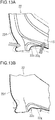
- the shortest distance d (refer to FIG.
- the plate thickness of the flange part was measured before and after the steps, and the plate thickness reduction rates of the stretch flanging deformation part were obtained.
- the plate thickness reduction rate in this case was the plate thickness reduction rate in the position where the plate thickness was most reduced in the domain of the stretch flanging deformation part, that is, the maximum plate thickness reduction rate.
- Table 1 The test result is shown in Table 1 as follows.
- the second-end-part-side groove part of the groove part was formed in the first step, and the remaining first-end-part-side groove part was formed in the second step.
- the plate thickness reduction rates of the stretch flanging deformation part in the first step, the second step and the trimming step were respectively 14.7%, 26.5% and 14.7%. That is, in the Inventive Example 2 of the present invention, formability of the stretch flanging deformation part was enhanced as compared with the conventional example 2.
- the stretch flanging deformation in the stretch flanging deformation part can be reduced, and rupture in the stretch flanging deformation part can be suppressed.
- the production method of a press-formed product of the present invention is useful in production of a press-formed product in the shape conforming to an automobile lower arm.
- the production method of the present invention is useful for production of a lower arm with a high strength and a high rigidity.
Landscapes
- Engineering & Computer Science (AREA)
- Mechanical Engineering (AREA)
- Shaping Metal By Deep-Drawing, Or The Like (AREA)
- Vehicle Body Suspensions (AREA)
- Bending Of Plates, Rods, And Pipes (AREA)
- Vehicle Interior And Exterior Ornaments, Soundproofing, And Insulation (AREA)
Abstract
Description
- The present invention relates to a method for producing a press-formed product (example: an automobile lower arm) from a blank metal plate by press-working. Further, the present invention relates to an automobile lower arm (hereinafter, simply referred to as "a lower arm") produced by the production method.
- In an automobile, vehicle wheels are mounted to a vehicle body via a suspension system (a suspension). One of members that constitute the suspension system is a lower arm. One end part of the lower arm is attached to the vehicle body via a frame (more specifically, a suspension member) of the suspension system. A vehicle wheel (more specifically, a wheel) is attached to the other end part of the lower arm. From the viewpoint of reduction in weight, it is desirable to adopt a press-formed product to the lower arm.
-
FIG. 1 andFIG. 2 are perspective views schematically showing shape examples of the press-formed products that are usable as lower arms. Among these Figures,FIG. 1 shows a press-formed product of a first example, andFIG. 2 shows a press-formed product of a second example. Press-formedproducts 10 shown inFIG. 1 andFIG. 2 each includes amain body part 11 and aprotruded part 12. Themain body part 11 extends in an L-shape or a bow-shape along a lengthwise direction in plan view. Of both ends of themain body part 11, one end part (hereinafter, also referred to as "a first end part") 11a is an end part that is attached to an automobile vehicle body. Hereinafter, thefirst end part 11a will also be referred to as "the vehicle body attaching end part". The other end part (hereinafter, also referred to as "a second end part") 11b is an end part that is attached to an automobile vehicle wheel. Hereinafter, thesecond end part 11b will also be referred to as "the vehicle wheel attaching end part". In each ofFIG. 1 andFIG. 2 , a side to be connected to the vehicle wheel will be designated by reference sign "W", whereas a side to be connected to a vehicle body will be designated by reference sign "B". - The
protruded part 12 protrudes outward of bending from a bent part of themain body part 11.FIG. 1 andFIG. 2 each show an embodiment in which theprotruded part 12 is provided substantially in a middle in the lengthwise direction of themain body part 11. As well as thefirst end part 11a of themain body part 11, theprotruded part 12 is a part that is attached to an automobile vehicle body. - Sectional shapes of the
main body part 11 and theprotruded part 12 are both groove-shaped. That is, themain body part 11 and theprotruded part 12 each includetop plate parts vertical wall parts vertical wall parts 14a to 14c each extend from opposite sides of thetop plate parts top plate part 13a of themain body part 11, agroove part 15 along the lengthwise direction of themain body part 11 is provided. - In a case of the press-formed
product 10 of the first example shown inFIG. 1 , thegroove part 15 is provided in a domain on the first end part (the vehicle body attaching end part) 11a side from a root of theprotruded part 12 in the surface of thetop plate part 13a. That is, thegroove part 15 is provided to a vicinity of thefirst end part 11a from a vicinity of the root of theprotruded part 12. Thegroove part 15 becomes deeper toward thefirst end part 11a. Consequently, a bottom surface of thegroove part 15 is an inclined surface. Note that the depth of the groove part is made constant without inclining the bottom surface of the groove part in some cases. - In the case of the press-formed
product 10 of the second example shown inFIG. 2 , thegroove part 15 is provided in a domain from the first end part (the vehicle body attaching end part) 11a to the second end part (the vehicle wheel attaching end part) 11b so as to pass through the root of theprotruded part 12, in the surface of thetop plate part 13a of themain body part 11. - Among the
vertical wall parts 14a to 14c, thevertical wall part 14a that extends from the first end part (the vehicle body attaching end part) 11a of themain body part 11 to theprotruded part 12 has a bay-shaped corner part 16 that connects themain body part 11 and theprotruded part 12. Hereinafter, thevertical wall part 14a will also be referred to as "the first vertical wall part". Aridge part 17 is formed by the firstvertical wall part 14a and thetop plate parts FIG. 1 andFIG. 2 ). In theridge part 17, a portion overlaid on thecorner part 16 is in a circular-arc shape. In theridge part 17, an angle that is formed by a portion which is on themain body part 11 side from thecorner part 16 and a portion which is on theprotruded part 12 side from thecorner part 16 is an acute angle. - Hereinafter, the
vertical wall part 14b that extends from the first end part (the vehicle body attaching end part) 11a of themain body part 11 to the second end part (the vehicle wheel attaching end part) 11b of themain body part 11 will also be referred to as "the second vertical wall part". Thevertical wall part 14c that extends from the second end part (the vehicle wheel attaching end part) 11b of themain body part 11 to theprotruded part 12 will also be referred to as "the third vertical wall part". - The press-formed
products 10 in the shapes as above are formed by applying press-working to blank metal plates. In accordance with necessity, restriking is applied to a region that cannot be formed by press-working, such as a very small R part, and thereby shape finish or shape fixation are performed. Further, for the purpose of finishing to a final shape, trimming, boring, welding and the like are applied in accordance with necessity. - When the lower arm as a press-formed product is produced, the type of forming that is applied to a blank metal plate is mainly stretch flanging. The prior arts concerning stretch flanging include the following.
-
Japanese Patent Application Publication No. 2011-230189 -
Japanese Patent Application Publication No. 2009-160655 Patent Literature 2, as the blank metal plate, a blank is used, which is composed of a blank part for a substrate corresponding to a flat-shaped substrate, and a blank part for a concave-shaped flange that is bending-formed into a concave-shaped outer circumferential edge of the blank part for a substrate. The concave-shaped blank part is constituted of a blank part for a convex-shaped flange where stretch flanging deformation occurs, and a blank part for an adjacent flange that is adjacent to the blank part for a convex-shaped flange. An outer circumferential edge of the blank part for a convex-shaped flange is formed in a predetermined range.Patent Literature 2 indicates that thereby, tensile stress concentration that occurs to the convex-shaped flange part of the press-formed product can be dispersed to both end portions, and a stretch flange crack can be suppressed. -
Japanese Patent Application Publication No. 06-87039 -
- Patent Literature 1:
Japanese Patent Application Publication No. 2011-230189 - Patent Literature 2:
Japanese Patent Application Publication No. 2009-160655 - Patent Literature 3:
Japanese Patent Application Publication No. 06-87039 - Conventionally, the lower arm of a press-formed product is produced by sequentially going through a first step and a second step as follows. In the first step, draw-forming is applied to a blank metal plate by press-working. In the second step, bending is applied to the metal plate which is draw-formed in the first step, by press-working.
-
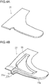
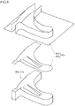
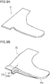
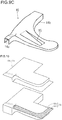
FIG. 3A to FIG. 3C , andFIG. 4A to FIG. 4C each relates to a press-formed product usable as a lower arm, and each is a perspective view for explaining an example of a production process step of a conventional method. Among these Figures,FIG. 3A to FIG. 3C show a case of producing the press-formedproduct 10 of the first example shown inFIG. 1 , andFIG. 4A toFIG. 4C show a case of producing the press-formedproduct 10 of the second example shown inFIG. 2 . Further,FIG. 3A andFIG. 4A show shapes of respective blank metal plates.FIG. 3B andFIG. 4B show shapes of the metal plates after the respective first steps.FIG. 3C andFIG. 4C show shapes of the press-formed products obtained by going through the respective second steps. In order to obtain the press-formedproducts 10 in the shapes shown inFIG. 3C andFIG. 4C , trimming is sometimes performed in an upstream step or a downstream step of the second step. -
FIG. 5 andFIG. 7 are perspective views schematically showing shape examples of a press die that is used in the first step of the conventional method.FIG. 6 andFIG. 8 are perspective views schematically showing shape examples of a press die that is used in the second step of the conventional method. Among these Figures,FIG. 5 andFIG. 6 each show the case of producing the press-formed product of the first example shown inFIG. 1 , andFIG. 7 andFIG. 8 each show the case of producing the press-formed product of the second example shown inFIG. 2 . - When the press-formed
product 10 of the first example shown inFIG. 1 is produced, adie 41a is used as anupper die 40a in the first step, as shown inFIG. 5 . As alower die 50a, apunch 51a and ablank holder 52a that are paired with theupper die 40a are used. The same applies to the case of producing the press-formedproduct 10 of the second example shown inFIG. 2 , as shown inFIG. 7 .FIG. 5 andFIG. 7 each show a shape of a front end part (a surface that abuts on the metal plate) with respect to the die 41 a, and a shape of a front end part (a surface that abuts on the metal plate) with respect to theblank holder 52a, in order to make the configuration easily understandable. - In the case of producing the press-formed
product 10 of the first example shown inFIG. 1 , adie 41b and apad 42b are used as anupper die 40b in the second step, as shown inFIG. 6 . As alower die 50b, apunch 51b which is paired with theupper die 40b is used. As shown inFIG. 8 , the same applies to the case of producing the press-formedproduct 10 of the second example shown inFIG. 2 .FIG. 6 andFIG. 8 each show a shape of a front end part (a surface that abuts on the metal plate) with respect to thedie 41b, and shows a shape of a front end part (a surface that abuts on the metal plate) with respect to thepad 42b, in order to make the configuration easily understandable. - As shown in
FIG. 3A ,FIG. 3B andFIG. 5 , in the case of producing the press-formedproduct 10 of the first example shown inFIG. 1 , press-working is applied to ablank metal plate 21 by using the die 41 a, thepunch 51a and theblank holder 52a in the first step by the conventional method, whereby a surface shape of a top plate part is formed throughout an entire range. Thereby, agroove part 15 is entirely formed. At the same time, the vertical wall part (the first vertical wall part) 14a is formed, which extends to the protruded part from the first end part (the vehicle body attaching end part) of the main body part, among the vertical wall parts. At this time, working of theblank metal plate 21 advances in a state in which an outer side of the firstvertical wall part 14a is held by theblank holder 52a and thedie 41a. A forming mode in the first step is draw-forming. The same applies to the case of producing the press-formedproduct 10 of the second example shown inFIG. 2 , as shown inFIG. 4A, FIG. 4B andFIG. 7 . - As shown in
FIG. 3B, FIG. 3C andFIG. 6 , in the case of producing the press-formedproduct 10 of the first example shown inFIG. 1 , in the second step by the conventional method, press-working is applied to themetal plate 22 after the first step by using thedie 41b, thepad 42b and thepunch 51b. Thereby, the remaining vertical wall parts, that is, the secondvertical wall part 14b and the thirdvertical wall part 14c are formed. At this time, in order to prevent a positional deviation of themetal plate 22, the working of themetal plate 22 advances in a state where a domain of the top plate part in themetal plate 22 is held by thepad 42b and thepunch 51b. A forming mode in the second step is bending. The same applies to the case of producing the press-formedproduct 10 of the second example shown inFIG. 2 , as shown inFIG. 4B ,FIG. 4C andFIG. 8 . - When a press-formed product is produced by the conventional method as above, rupture may occur in the first step or the second step. In the first step or the second step, the rupture occurs to a
part 22c (hereinafter, also referred to as "a stretch flanging deformation part") that undergoes stretch flanging deformation. The stretchflanging deformation part 22c corresponds to acorner part 16 that connects the main body part and the protruded part in the firstvertical wall part 14a, and anouter side domain 22h of the corner part 16 (refer to shaded portions inFIG. 3B andFIG. 4B ). - In the first step according to the conventional method, inflow of the material from the top plate part to the stretch
flanging deformation part 22c is promoted by using theblank holder 52a, and stretch flanging deformation is reduced. However, even though countermeasure like this is applied, rupture may occur to the stretchflanging deformation part 22c. - In this respect, in the technique of Patent Literature 1 described above, in order to enhance stretch flanging performance, a high-strength steel plate of a precipitation strengthening type is used as a steel plate, and press-working is performed in a warm condition. However, in this technique, the step of heating the steel plate is required, and therefore, productivity is reduced as compared with press-working in a cold condition.
- In the technique of
Patent Literature 2, by optimizing the shape of the blank metal plate, stress concentration that occurs to the region which undergoes stretch flanging deformation is dispersed, and a stretch flange crack is suppressed. However, there is a limitation on dispersion of stress concentration by optimization of the shape of the starting material, and suppression of rupture in the stretch flanging deformation part is insufficient. - In the technique of Patent Literature 3 described above, burring is used. A draw part which is formed by the burring is in an axisymmetric cylindrical shape. Meanwhile, a stretch flanging deformation part of the lower arm is not in an axisymmetric shape. Consequently, even if inflow of the material is promoted by drawing, a crack may occur to the stretch flanging deformation part.
- The present invention is made in the light of the above described circumstances, and an objective of the present invention is to provide a method for producing a press-formed product that reduces stretch flanging deformation in a stretch flanging deformation part, and can restrain rupture in the stretch flanging deformation part, at a time of producing the press-formed product in a shape conforming to an automobile lower arm. Further, an objective of the present invention is to provide an automobile lower arm with high strength in which rupture is suppressed in the stretch flanging deformation part.
- A method for producing a press-formed product according to one embodiment of the present invention is a method for producing a press-formed product from a blank metal plate.
- The press-formed product includes a main body part that bends along a lengthwise direction in plan view and has a first end part and a second end part respectively on both ends of the main body part, and a protruded part that protrudes outward of bending from a bent part of the main body part.
- The main body part and the protruded part each include top plate parts and vertical wall parts each extending from opposite sides of the top plate parts.
- A groove part along the lengthwise direction of the main body part is provided on a surface of the top plate part of the main body part.
- Among the vertical wall parts, the vertical wall part extending from the first end part of the main body part to the protruded part has a corner part connecting the main body part and the protruded part.
- In a ridge part formed by the top plate part and the vertical wall part extending from the first end part of the main body part to the protruded part, an angle that is formed by a part which is on the main body part side from the corner part and a part which is on the protruded part side from the corner part is an acute angle.
- The method for producing the press-formed product includes a first step; and a second step.
- In the first step, by applying press-working to the blank metal plate, a surface shape on the second end part side from the bent part of the main body part is formed, in a surface shape of the top plate part, and further the vertical wall part extending from the first end part side of the main body part to the protruded part is formed.
- In the second step, a surface shape on the first end part side from the bent part of the main body part is formed, in the surface shape of the top plate part, by applying press-working to the blank metal plate after the first step.
- In the above described production method, the following configuration can be adopted.
- The groove part of the press-formed product is provided in a domain from the first end part to the second end part so as to pass through a root of the protruded part, in the surface of the top plate part of the main body part.
- In the first step, a part on the second end part side of the groove part is formed.
- In the second step, a part on the first end part side of the groove part is formed.
- In the case of the production method, in the first step, when a circle having a radius of 35% of a length of the main body part is drawn centered at a point that is located nearest to the second end part side in the corner part, a part or a whole of a portion on the second end part side of the groove part is preferably located in the circle.
- Further, in the above described production method, the following configuration can be adopted.
- The groove part of the press-formed product is provided in a domain on the first end part side from a root of the protruded part, in the surface of the top plate part of the main body part,
- The groove part is not formed in the first step.
- The groove part is formed in the second step.
- In any one of the production methods described above, the following configuration can be adopted.
- The press-formed product is an automobile lower arm.
- The first end part and the protruded part of the main body part are attached to a vehicle body of an automobile.
- The second end part of the main body part is attached to a vehicle wheel of the automobile.
- An automobile lower arm according to one embodiment of the present invention is formed from a blank metal plate by press-working.
- The lower arm includes a main body part that bends along a lengthwise direction in plan view and has a vehicle body attaching end part and a vehicle wheel attaching end part respectively on both ends of the main body part, and a vehicle body attaching protruded part that protrudes outward of bending from a bent part of the main body part.
- The main body part and the protruded part each include top plate parts and vertical wall parts each extending from opposite sides of the top plate parts.
- A groove part along the lengthwise direction of the main body part is provided on a surface of the top plate part of the main body part.
- Among the vertical wall parts, the vertical wall part extending from the vehicle body attaching end part of the main body part to the protruded part has a corner part connecting the main body part and the protruded part.
- In a ridge part formed by the vertical wall part extending from the vehicle body attaching end part of the main body part to the protruded part, and the top plate part, an angle that is formed by a part which is on the main body part side from the corner part and a part which is on the protruded part side from the corner part is an acute angle.
- A tensile strength TS [MPa] is 440 MPa or more.
- A maximum height Hmax [mm] of the corner part of the vertical wall part satisfies Formula (1) as follows:

- The method for producing a press-formed product of the present invention can reduce stretch flanging deformation in a stretch flanging deformation part, and restrain rupture in the stretch flanging deformation part, by going through the first step and the second step at the time of producing the press-formed product in the shape conforming to an automobile lower arm. Further, the automobile lower arm of the present invention has high strength, with rupture suppressed in the stretch flanging deformation part.
-
- [
FIG. 1] FIG. 1 is a perspective view schematically showing a press-formed product of a first example. - [
FIG. 2] FIG. 2 is a perspective view schematically showing a press-formed product of a second example. - [
FIG. 3A] FIG. 3A relates to a press-formed product of a first example, is a perspective view for explaining an example of a production process step of a conventional method, and shows a shape of a blank metal plate. - [
FIG. 3B] FIG. 3B relates to the press-formed product of the first example, is a perspective view for explaining an example of the production process step of the conventional method, and shows a shape of the metal plate after a first step. - [
FIG. 3C] FIG. 3C relates to the press-formed product of the first example, is a perspective view for explaining an example of the production process step of the conventional method, and shows a shape of a press-formed product that is obtained by going through a second step. - [
FIG. 4A] FIG. 4A relates to a press-formed product of a second example, is a perspective view for explaining an example of a production process step of a conventional method, and shows a shape of a blank metal plate. - [
FIG. 4B] FIG. 4B relates to the press-formed product of the second example, is a perspective view for explaining an example of the production process step of the conventional method, and shows a shape of the metal plate after a first step. - [
FIG. 4C] FIG. 4C relates to the press-formed product of the second example, is a perspective view for explaining an example of the production process step of the conventional method, and shows a shape of a press-formed product obtained by going through a second step. - [
FIG. 5] FIG. 5 relates to the press-formed product of the first example, and is a perspective view schematically showing a shape example of a press die that is used in the first step of the conventional method. - [
FIG. 6] FIG. 6 relates to the press-formed product of the first example, and is a perspective view schematically showing a shape example of a press die that is used in the second step of the conventional method. - [
FIG. 7] FIG. 7 relates to the press-formed product of the second example, and is a perspective view schematically showing a shape example of a press die that is used in the first step of the conventional method. - [
FIG. 8] FIG. 8 relates to the press-formed product of the second example, and is a perspective view schematically showing a shape example of a press die that is used in the second step of the conventional method. - [
FIG. 9A] FIG. 9A is a perspective view for explaining an example of a production process step of a first embodiment, and shows a shape of a blank metal plate. - [
FIG. 9B] FIG. 9B is a perspective view for explaining an example of the production process step of the first embodiment, and shows a shape of the metal plate after a first step. - [
FIG. 9C] FIG. 9C is a perspective view for explaining an example of the production process step of the first embodiment, and shows a shape of a press-formed product obtained by going through a second step. - [
FIG. 10] FIG. 10 is a perspective view schematically showing a shape example of a press die that is used in the first step of the first embodiment. - [
FIG. 11A] FIG. 11A is a perspective view for explaining an example of a production process step of a second embodiment, and shows a shape of a blank metal plate. - [
FIG. 11B] FIG. 11B is a perspective view for explaining an example of the production process step of the second embodiment, and shows a shape of the metal plate after the first step. - [
FIG. 11C] FIG. 11C is a perspective view for explaining an example of the production process step of the second embodiment, and shows a shape of a press-formed product obtained by going through a second step. - [
FIG. 12] FIG. 12 is a perspective view schematically showing a shape example of a press die that is used in the first step of the second embodiment. - [
FIG. 13A] FIG. 13A is a plane view showing a flow state of a material of a stretch flanging deformation part in the first step, and shows a case by the conventional method. - [
FIG. 13B] FIG. 13B is a plan view showing a flow state of a material of a stretch flanging deformation part in the first step, and shows a case by a comparative method. - [
FIG. 13C] FIG. 13C is a plan view showing a flow state of a material of a stretch flanging deformation part in the first step, and shows a case according to the second embodiment. - [
FIG. 14] FIG. 14 is a diagram showing a relation between a tensile strength of a blank metal plate and a limit forming height by press-working. - In order to achieve the above described objectives, the present inventor has conducted various analyses and tests, and kept earnest studies. As a result, the present inventor has obtained the following finding. When a press-formed product in a shape conforming to a lower arm, that is, a press-formed product including a main body part and a protruded part and provided with a groove part on a surface of a top plate part is produced by press-working, if a shape of a press die is optimized in a first step, inflow of a material to a stretch flanging deformation part is further promoted. Thereby, stretch flanging deformation in the stretch flanging deformation part is reduced, and rupture in the stretch flanging deformation part is suppressed. As a result, it becomes possible to produce a press-formed product (a lower arm) in which rupture is suppressed in the stretch flanging deformation part.
- More specifically, irrespective of an installation range of the groove part, in the first step, a surface shape on a second end part side from a bent part of the main body part in a surface shape of the top plate part is formed without forming a surface shape on a first end part side from the bent part of the main body part, and a vertical wall part that extends from the first end part side of the main body part to the protruded part can be further formed. Subsequently, in a second step, the surface shape on the first end part side from the bent part of the main body part, in the surface shape of the top plate part can be formed. When the press-formed product is a lower arm, the first end part is a vehicle body attaching end part, and the second end part is a vehicle wheel attaching end part.
- For example, in a case of producing a press-formed product in which a groove part is provided in only a domain on the first end part side from the bent part of the main body part, the groove part is not formed in the first step, but the groove part is formed in the second step. Further, in a case of producing a press-formed product in which a groove part is provided in a domain from the first end part to the second end part, a part on the second end part side of the groove part is formed in the first step, and a remaining part (the part on the first end part side) of the groove part is formed in the second step.
- Hereinafter, embodiments of the present invention will be described with reference to Figures. Here, a case where the press-formed product is a lower arm will be illustrated.
-
FIG. 9A to FIG. 9C relate to a press-formed product usable as a lower arm, and are perspective views explaining an example of a production process step according to a production method of a first embodiment. Among these Figures,FIG. 9A shows a shape of a blank metal plate.FIG. 9B shows a shape of the metal plate after a first step.FIG. 9C shows a shape of the press-formed product obtained by going through a second step. The production method of the first embodiment is applied to a case of producing a press-formedproduct 10 of a first example shown inFIG. 1 . Agroove part 15 of the press-formedproduct 10 is provided in only a domain on a first end part (a vehicle body attaching end part) 11a side from a root of aprotruded part 12, in a surface of atop plate part 13a of amain body part 11, as shown inFIG. 1 andFIG. 9C . In order to obtain the press-formedproduct 10 in a shape shown inFIG. 9C , trimming is sometimes performed in an upstream process or a downstream process of a second step. -
FIG. 10 is a perspective view schematically showing a shape example of a press die that is used in the first step in the production method of the first embodiment. As shown inFIG. 10 , in the first step, adie 41c is used as anupper die 40c. As alower die 50c, apunch 51c and ablank holder 52c that are paired with theupper die 40c are used. In order to make a configuration easily understandable,FIG. 10 shows a shape of a front end part (a surface that abuts on the metal plate) with respect to the die 41 c, and shows a shape of a front end part (a surface that abuts on the metal plate), with respect to theblank holder 52c. - In the second step, a press die shown in
FIG. 6 described above is used as in the second step of the conventional method. That is, as shown inFIG. 6 described above, adie 41b and apad 42b are used as anupper die 40b. As alower die 50b, apunch 51b which is paired with theupper die 40b is used. - As shown in
FIG. 9A, FIG. 9B andFIG. 10 , in the first step, by applying press-working to ablank metal plate 21 by using thedie 41 c, thepunch 51c and theblank holder 52c, a surface shape on the second end part side from the bent part of the main body part is formed, in the surface shape of the top plate part. In the press-formedproduct 10 which is a target in the first embodiment, thegroove part 15 is not present on the surface of thetop plate part 13a on thesecond end part 11b side (refer toFIG. 1 ). Consequently, thegroove part 15 is not formed, as shown inFIG. 9B . At the same time, a vertical wall part (a first vertical wall part) 14a that extends to the protruded part from the first end part (the vehicle body attaching end part) of the main body part in the vertical wall parts is formed. At this time, working of theblank metal plate 21 advances in a state where the outer side of the firstvertical wall part 14a is held by theblank holder 52c and thedie 41c. A forming mode in the first step is draw-forming. - As shown in
FIG. 6 ,FIG. 9B andFIG. 9C , in the second step, a surface shape on the first end part side from the bent part of the main body part is formed, in the surface shape of the top plate part, by applying press-working to ametal plate 22 after the first step, by using thedie 41b, thepad 42b and thepunch 51b similarly to the second step of the conventional method. Thereby, as shown inFIG. 9C , thegroove part 15 is formed. At the same time, the remaining vertical wall parts, that is, a secondvertical wall part 14b and a thirdvertical wall part 14c are formed. At this time, in order to prevent a positional deviation of themetal plate 22, the working of themetal plate 22 advances in a state where a domain of the top plate part in themetal plate 22 is held by thepad 42b and thepunch 51b. A forming mode in the second step is bending. - Here, in the conventional method, in the first step, the
vertical wall part 14a is formed with thegroove part 15, as described above. At this time, the material in the domain on the second end part (the vehicle wheel attaching end part) side from a root of the protruded part in the top plate part of the main body part is brought into both thegroove part 15 and the stretchflanging deformation part 22c (refer to the broken line arrows inFIG. 3B described above). By the bringing of the material to thegroove part 15, the bringing of the material to the stretchflanging deformation part 22c is reduced. - In contrast with this, in the first embodiment, in the first step, the first
vertical wall part 14a is formed without forming thegroove part 15. At this time, a material in a domain on the second end part (the vehicle wheel attaching end part) side from the root of the protruded part in the top plate part of the main body part is brought into only the stretchflanging deformation part 22c (refer to the broken line arrow inFIG. 9B ). Since there is no bringing of the material into thegroove part 15, bringing of the material to the stretchflanging deformation part 22c is further promoted. As a result, the stretch flanging deformation in the stretchflanging deformation part 22c is reduced, and rupture in the stretch flanging deformation part is suppressed. Accordingly, it becomes possible to produce a press-formed product - (the lower arm) in which rupture is suppressed in the stretch flanging deformation part.
- As described above, suppression of rupture in the stretch flanging deformation part by the production method of the first embodiment is by the bringing of the material in the first step. A mechanism of the suppression of rupture similarly applies to the second step.
- According to the production method of the first embodiment, stretch flanging deformation in the stretch flanging deformation part is reduced as described above. Consequently, even in the case of using a high-tensile strength steel plate as the blank metal plate, rupture in the stretch flanging deformation part can be suppressed. Further, it becomes possible to more increase a forming height of a vertical wall part, in particular, a forming height of a corner part of the first vertical wall part to be the stretch flanging deformation part, and a degree of freedom of design of the press-formed product (the lower arm) is enhanced.
- In the case of using a high-tensile strength steel plate as the blank metal plate, if the tensile strength becomes more than 440 MPa, occurrence of rupture in the stretch flanging deformation part becomes remarkable. In this respect, according to the production method of the first embodiment, rupture in the stretch flanging deformation part can be suppressed even in the case of using the high-tensile strength steel plate with a tensile strength of 440 MPa or more. Consequently, the production method of the first embodiment is especially useful in the case of using a high-tensile strength steel plate with a tensile strength of 440 MPa or more. Thereby, a press-formed product (a lower arm) with a high strength and a high rigidity in which rupture is suppressed in the stretch flanging deformation part is obtained.
- The production method of the first embodiment described above can be changed as follows.
- Forming of the vertical wall part (the second vertical wall part) 14b extending from the first end part (the vehicle body attaching end part) of the main body part to the second end part (the vehicle wheel attaching end part) of the main body part may be performed in either of the first step and the second step. Further, if a downstream step of applying press-working by using another press die is provided subsequently to the second step, forming of the second
vertical wall part 14b can be performed in the downstream step. From the viewpoint of further promoting inflow of the material to the stretchflanging deformation part 22c in the first step, forming of the secondvertical wall part 14b is preferably performed in the second step or the downstream step of the second step. - Forming of the vertical wall part (the third vertical wall part) 14c extending to the protruded part from the second end part (the vehicle wheel attaching end part) of the main body part may be performed in either of the first step and the second step. Further, a downstream step of applying press-working by using another press die is provided subsequently to the second step, forming of the third
vertical wall part 14c can be performed in the downstream step. From the viewpoint of further promoting inflow of the material to the stretchflanging deformation part 22c in the first step, forming of the thirdvertical wall part 14c is preferably performed in the second step or the downstream step of the second step. - In the second step, the pad can be omitted, as the upper die which is paired with the punch. Press-working in this case is performed by the die and the punch. However, in this case, in order to form the
groove part 15, a convex part corresponding to thegroove part 15 needs to be provided in the die. Further, in order to prevent the position of the metal plate from deviating at the time of press-working, a guide pin is preferably installed. - In fact, if the
pad 42b is used in the second step, forming of thegroove part 15 precedes forming of the secondvertical wall part 14b and the thirdvertical wall part 14c. Thereby, inflow of the material toward thegroove part 15 from a region that is formed into the secondvertical wall part 14b is promoted. As a result, outflow of the material from the stretchflanging deformation part 22c is more reduced, so that stretch flanging deformation in the stretchflanging deformation part 22c is more reduced, and rupture in the stretchflanging deformation part 22c is more suppressed. Consequently, use of the pad is preferable in the second step. - The first step and the second step may be continued, or in accordance with necessity, another step (example: a piercing step, a trimming step or the like) may be added to between the first step and the second step.
- Trimming is not indispensable. This is because if the outline shape of the blank metal plate is set properly, the shape of the press-formed product which is obtained by going through the first step and the second step can be formed into the product shape.
-
FIG. 11A to FIG. 11C relate to a press-formed product usable as a lower arm, and are perspective views each explaining an example of a production process step according to a production method of a second embodiment. Among these Figures,FIG. 11A shows a shape of a blank metal plate.FIG. 11B shows a shape of a metal plate after a first step.FIG. 11C shows a shape of the press-formed product obtained by going through a second step.FIG. 12 is a perspective view schematically showing a shape example of a press die that is used in the first step in the production method of the second embodiment. The production method of the second embodiment is applied to a case of producing the press-formedproduct 10 of the second example shown inFIG. 2 . As shown inFIG. 2 andFIG. 11C , thegroove part 15 of the press-formedproduct 10 is provided in a wide-ranging domain from the first end part (the vehicle body attaching end part) 11a to the second end part (the vehicle wheel attaching end part) 11b so as to pass through the root of theprotruded part 12, in a surface of thetop plate part 13a of themain body part 11. - The second embodiment is based on the configuration of the aforementioned first embodiment. Hereinafter, explanation overlapping with the first embodiment will be properly omitted.
- As shown in
FIG. 11A, FIG. 11B andFIG. 12 , in a first step, a surface shape on a second end part side from a bent part of a main body part is formed, in a surface shape of a top plate part, by applying press-working to theblank metal plate 21 by using thedie 41c, thepunch 51c and theblank holder 52c. Thereby, as shown inFIG. 11B , a part (hereinafter, also referred to as "a second-end-part-side groove part") 22a on the second end part (the vehicle wheel attaching end part) 11b side of thegroove part 15 is formed. At the same time, the vertical wall part (the first vertical wall part) 14a extending to a protruded part from a first end part (a vehicle body attaching end part) of the main body part, in the vertical wall parts, is formed. - In a second step, the press die shown in
FIG. 8 described above is used as in the second step of the conventional method. As shown inFIG. 8 ,FIG. 11B andFIG. 11C , in the second step, a surface shape on a first end part side from the bent part of the main body part is formed, in the surface shape of the top plate part, by applying press-working to themetal plate 22 after the first step, by using thedie 41b, thepad 42b and thepunch 51b. Thereby, as shown inFIG. 11C , a remaining part (hereinafter, also referred to as "a first-end-part-side groove part") of thegroove part 15 is formed. At the same time, remaining vertical wall parts, that is, the secondvertical wall part 14b and the thirdvertical wall part 14c are formed. - Here, a mechanism of rupture in the stretch
flanging deformation part 22c being suppressed by the production method of the second embodiment will be described. -
FIG. 13A to FIG. 13C are plan views each showing a flow state of a material of a stretch flanging deformation part in the first step. Among these Figures,FIG. 13A shows a case according to the conventional method.FIG. 13B shows a case according to a comparative method.FIG. 13C shows a case according to the second embodiment. These Figures each show a shape of the stretchflanging deformation part 22c and a periphery thereof in themetal plate 22 after the first step. Shapes of the blank metal plates are shown by the two-dot chain lines. - As shown in
FIG. 13A , in the conventional method, theentire groove part 15 from the first end part to the second end part is formed in the first step. Consequently, anouter edge 22f (refer to the thick line portion inFIG. 13A ) of a part that is formed into the third vertical wall part in the second step moves to thegroove part 15 side and the stretchflanging deformation part 22c side. That is, in the first step of the conventional method, the material flows to the arrow to which shading is applied inFIG. 13A , and the material flows into the stretchflanging deformation part 22c. - Meanwhile, the
outer edge 22g (refer to the thick line portion inFIG. 13A ) of the first vertical wall part moves to thegroove part 15 side. Consequently, in the first step of the conventional method, the material flows to the direction shown by the arrow to which cross-hatching is applied inFIG. 13A , and the material flows out from the stretchflanging deformation part 22c. By outflow of the material from the stretchflanging deformation part 22c, deformation in the stretchflange deformation part 22c increases, where rupture occurs. - The comparative method is a method for reference which does not form the
groove part 15 in the first step, as shown inFIG. 13B . In the comparative method, shearing deformation advances in a domain enclosed by the broken line inFIG. 13B , at the time of the material flowing into the stretchflanging deformation part 22c. Since deformation resistance of the shearing deformation is large, inflow of the material to the stretchflanging deformation part 22c is inhibited. As a result, theouter edge 22f (refer to the thick line portion inFIG. 13B ) of a part which is to be formed into the third vertical wall part in the second step moves to the stretchflanging deformation part 22c side, but a moving amount of theouter edge 22f decreases as compared with the conventional method. That is, inflow of the material to the stretchflanging deformation part 22c is reduced. - Meanwhile, the
outer edge 22g (refer to the thick line portion inFIG. 13B ) of the first vertical wall part moves inward. However, since a groove part is not formed in the first step of the comparative method, a moving amount of theouter edge 22g decreases as compared with the conventional method. Consequently, according to the comparative method, outflow of the material from the stretchflanging deformation part 22c is reduced as compared with the conventional method. - As above, in the comparative method, inflow of the material to the stretch
flanging deformation part 22c in the direction shown by the arrow to which shading is applied inFIG. 13B is reduced as compared with the conventional method. Further, outflow of the material from the stretchflanging deformation part 22c in the direction shown by the arrow to which cross-hatching is applied inFIG. 13B is reduced. As a result, deformation in the stretchflanging deformation part 22c increases more, and occurrence of rupture in this part becomes remarkable. - In contrast with this, in the second embodiment, only the second-end-part-
side groove part 22a of the groove part is formed in the first step, as shown inFIG. 13C . In this case, the material flows into the second-end-part-side groove part 22a and the stretchflanging deformation part 22c. The material flows into the second-end-part-side groove part 22a, whereby occurrence of sharing deformation as in the comparative method is prevented, and inflow of the material to the stretchflanging deformation part 22c is promoted. Consequently, theouter edge 22f (refer to the thick line portion inFIG. 13C ) of the part which is to be formed into the third vertical wall part in the second step moves to thegroove part 15 side and the stretchflanging deformation part 22c side as in the conventional method. That is, in the first step of the second embodiment, inflow of the material to the stretchflanging deformation part 22c is kept to the same extent as in the conventional example. - Meanwhile, the
outer edge 22g (refer to the thick line portion inFIG. 13C ) of the first vertical wall part moves inward. However, since only the second-end-part-side groove part 22a is formed in the first step of the second embodiment, the moving amount of theouter edge 22g decreases as compared with the conventional method. Consequently, according to the second embodiment, outflow of the material from the stretchflanging deformation part 22c is reduced as compared with the conventional method. - As above, in the second embodiment, inflow of the material to the stretch
flanging deformation part 22c in the direction shown by the arrow to which shading is applied inFIG. 13C is kept at the same extent as compared with the conventional method. Further, outflow of the material from the stretchflanging deformation part 22c in the direction shown by the arrow to which cross-hatching is applied inFIG. 13C is reduced. As a result, stretch flanging deformation in the stretchflanging deformation part 22c is reduced, and occurrence of rupture in this part is suppressed. - In the case of the second embodiment, when a circle C is drawn centered at a
point 22d that is located nearest to the second end part (the vehicle wheel attaching end part) side of the corner part of the first vertical wall part which is the stretch flanging deformation part in the first step, as shown inFIG. 13C , a part or a whole of the second-end-part-side groove part 22a is preferably located inside the circle C. Here, a radius [mm] of the circle C is 35% of a length [mm] of themain body part 11. The length of themain body part 11 is a distance [mm] in a straight line from the first end part (the vehicle body attaching end part) 11a to the second end part (the vehicle wheel attaching end part) 11b as shown in theFIG. 2 described above. In measurement of the length of themain body part 11, as respective positions of thefirst end part 11a and thesecond end part 11b, center points P1 and P2 in a width direction in thetop plate part 13a of themain body part 11 are respectively adopted. - If a part or a whole of the second-end-part-
side groove part 22a is located inside the circle C, inflow of the material to the stretchflanging deformation part 22c attributable to forming the second-end-part-side groove part 22a is promoted more effectively in the first step. As a result, stretch flanging deformation in the stretchflanging deformation part 22c is more reduced, and occurrence of rupture in this part is more suppressed. From the viewpoint of increasing the effect more, the radius of the circle C is preferably 30% of the length of themain body part 11. - Further, when a part or a whole of the second-end-part-
side groove part 22a formed in the first step is located inside the circle C, anend part 22e of the second-end-part-side groove part 22a may be disposed on either of the first end part side and the second end part side, with thecenter point 22d of the circle C as a reference. However, if theend part 22e of the second-end-part-side groove part 22a is disposed at the first end part (the vehicle body attaching end part) side, there arises the fear of increasing outflow of the material from the stretchflanging deformation part 22c in the direction shown by the arrow to which cross-hatching is applied inFIG. 13C . Consequently, theend part 22e of the second-end-part-side groove part 22a is preferably disposed on the second end part (the vehicle wheel attaching end part) side from thecenter point 22d of the circle C. - As described above, suppression of rupture in the stretch flanging deformation part according to the production method of the second embodiment is by flow of the material in the first step. The mechanism of rupture suppression similarly applies to the second step.
- According to the production methods of the present embodiments described above, press-formed products in which rupture is suppressed in the stretch flanging deformation parts can be obtained even when a high-tensile strength steel plate with a tensile strength of 440 MPa-class is used as a blank metal plate. Consequently, the press-formed products of the present embodiments have a high strength, and rupture is suppressed in the stretch flanging deformation parts. A use purpose of the press-formed products is not limited as long as the press-formed products are in the shapes conforming to lower arms.
- Further, according to the production methods of the present embodiments, stretch flanging deformation can be reduced in the stretch flanging deformation parts. Consequently, formed heights of the vertical wall parts of the press-formed products, in particular, formed heights of the corner parts of the first vertical wall parts which are to be the stretch flanging deformation parts can be made higher.
- Here, a result of investigating a limit height capable of being formed by press-working will be shown, with respect to the height of the corner part of the first vertical wall part in a press-formed product. The limit forming height of the corner part was investigated for each of various steel plates with different tensile strengths in both the production method of the present embodiment and the conventional method. In the investigation, the actual values of the actual working tests conducted by the inventor and the result of FEM analysis were used.
-
FIG. 14 is a diagram showing a relation between a tensile strength of the blank metal plate and a limit forming height by press-working.FIG. 14 representatively shows a result of a case of using a steel plate of 590 MPa-class and a steel plate of 980 MPa-class. As shown inFIG. 14 , a limit forming height H [mm] of the corner part reduces proportionally to a tensile strength TS [MPa] of the steel plate in both of the cases of the production method of the present embodiment and the conventional method. Especially in the case of the conventional method, a limit forming height Hlim [mm] of the corner part is expressed by Formula (A) as follows.
- Meanwhile, in the case of the production method of the present embodiment, the limit forming height Hlim [mm] of the corner part is expressed by Formula (B) as follows.

- From the relations of Formula (A) and Formula (B) described above, the limit forming height according to the production method of the present embodiment increases by approximately 3 mm as compared with the conventional method. That is, according to the production method of the present embodiment, the forming height of the corner part can be made higher than the limit forming height of the conventional method expressed by Formula (A) described above.
- Accordingly, in the press-formed product of the present embodiment, a maximum height Hmax [mm] of the corner part of the first vertical wall part which is to be the stretch flanging deformation part can be made to satisfy Formula (1) as follows on the basis of Formula (A) described above. As a matter of course, the press-formed product of the present embodiment can be made the product having a tensile strength of 440 MPa or more.

- In order to confirm the effect of the present invention, tests on example 1 and example 2 below were carried out by FEM analyses. In the FEM analyses of both of example 1 and example 2, press-formed products usable as lower arms were produced by applying press-working to blank metal plates, and degrees of stretch flanging deformation were evaluated by plate thickness decrease rates of the stretch flanging deformation parts at this time.
- In the test of example 1, a press-formed product in the shape of the first example shown in
FIG. 1 described above was produced in order to confirm the effect of the first embodiment. The groove part of the press-formed product is provided in only the domain on the first end part side, in the surface of the top plate part of the main body part. At this time, a high-tensile strength steel plate with a plate thickness of 2.6 mm, and a tensile strength of 960 MPa-class was used as the blank metal plate. - In Inventive Example 1 of the present invention, the press dies shown in
FIG. 10 andFIG. 6 described above were used, and press-working was applied to the blank metal plate by the first step shown inFIG. 9A and FIG. 9B described above, and the second step shown inFIG. 9B andFIG. 9C described above. - Meanwhile, in the conventional example 1, the press dies shown in
FIG. 5 andFIG. 6 described above were used, and press-working was applied to the blank metal plate by the first step shown inFIG. 3A andFIG. 3B described above, and the second step shown inFIG. 3B and FIG. 3C described above. The other conditions were set as the same as in the Inventive Example 1 of the present invention. - In both of the Inventive Example 1 of the present invention and the conventional example 1, for the respective first steps and second steps, the plate thicknesses of the stretch flange parts were measured before and after the steps, and plate thickness reduction rates of the stretch flanging deformation parts were obtained. The plate thickness reduction rates here were set as the plate thickness reduction rates in the positions where the plate thicknesses were reduced most in domains of the stretch flanging deformation parts, that is, the maximum plate thickness reduction rates.
- In the conventional example 1, a whole of the groove part was formed in the first step. As a result, the plate thickness reduction rates of the stretch flanging deformation part in the first step and the second step were respectively 11.6% and 33.5%.
- In contrast with this, in the Inventive Example 1 of the present invention, a whole of the groove part was formed in the second step, without forming the groove part in the first step. The plate thickness reduction rates of the stretch flanging deformation part in the first step and the second step were respectively 8.0% and 26.3%. That is, in the Inventive Example 1 of the present invention, readily producing of the stretch flanging deformation part was enhanced as compared with the conventional example 1.
- From the above, it has become clear that according to the first embodiment, the stretch flanging deformation in the stretch flanging deformation part can be reduced, and rupture in the stretch flanging deformation part can be suppressed.
- In the test of example 2, the press-formed product in the shape of the second example shown in
FIG. 2 described above was produced in order to confirm the effect of the second embodiment. The groove part of the press-formed product was provided in a wide-ranging domain from the first end part (the vehicle body attaching end part) to the second end part (the vehicle wheel attaching end part), of the surface of the top plate part of the main body part. At this time, a high-tensile strength steel plate with a plate thickness of 2.6 mm and a tensile strength of 980 MPa-class was used as the blank metal plate. A distance in a straight line from the first end part to the second end part of the main body part, that is, the length of the main body part was 400 mm. - In Inventive Example 2 of the present invention, press-working was applied to the blank metal plate by the first step shown in
FIG. 11A and FIG. 11B described above, and the second step shown inFIG. 11B andFIG. 11C described above, by using the press dies shown inFIG. 12 andFIG. 8 described above. Trimming was applied to the resultant press-formed product. Thepoint 22d located nearest to the second end part side in the corner part of the first vertical wall part which is to be the stretch flanging deformation part was set as a reference, and theend part 22e of the second-end-part-side groove part 22a which is formed in the first step was disposed on the second end part side from thereference point 22d. The shortest distance d (refer toFIG. 13C described above) between the second-end-part-side groove part 22a and thereference point 22d was set as 40 mm. Consequently, when a circle having a radius of 35% of the length (400 mm) of the main body part, that is, a circle having a radius of 140 mm was drawn centered at thereference point 22d, a part of the second-end-part-side groove part 22a was in a state located in the circle. - Meanwhile, in the conventional example 2, press-working was applied to the blank metal plate by the first step shown in
FIG. 4A and FIG. 4B described above, and the second step shown inFIG. 4B andFIG. 4C described above, by using the press dies shown inFIG. 7 andFIG. 8 described above. Further, in Comparative Example 2 for reference, a whole of the groove part was formed in the second step without forming the groove part in the first step. The other conditions were set as the same as in the Inventive Example 2 of the present invention. - In each of the Inventive Example 2 of the present invention, the conventional example 2 and Comparative Example 2, for the respective first step, second step and trimming step, the plate thickness of the flange part was measured before and after the steps, and the plate thickness reduction rates of the stretch flanging deformation part were obtained. The plate thickness reduction rate in this case was the plate thickness reduction rate in the position where the plate thickness was most reduced in the domain of the stretch flanging deformation part, that is, the maximum plate thickness reduction rate. The test result is shown in Table 1 as follows.
- [Table 1]
TABLE 1 Category Formed part of groove part in first step Plate thickness reduction rate of stretch flanging deformation part (%) First step Second step Trimming step Conventional example 2 Whole 17.9 33.3 24.9 Comparative Example 2 None 28.6 38.5 29.7 Inventive Example 2 of present invention Second-end-part-side groove part 14.7 26.5 14.7 - From Table 1, the following is shown. In the conventional example 2, the whole of the groove part was formed in the first step. As a result, the plate thickness reduction rates of the stretch flanging deformation part in the first step, the second step and the trimming step were respectively 17.9%, 33.3% and 24.9%. In contrast with this, in the Comparative Example 2, the plate thickness reduction rates of the stretch flanging deformation part in the first step, the second step and the trimming step were all worsened.
- In the Inventive Example 2 of the present invention, the second-end-part-side groove part of the groove part was formed in the first step, and the remaining first-end-part-side groove part was formed in the second step. As a result, the plate thickness reduction rates of the stretch flanging deformation part in the first step, the second step and the trimming step were respectively 14.7%, 26.5% and 14.7%. That is, in the Inventive Example 2 of the present invention, formability of the stretch flanging deformation part was enhanced as compared with the conventional example 2.
- From the above, it has become clear that according to the second embodiment, the stretch flanging deformation in the stretch flanging deformation part can be reduced, and rupture in the stretch flanging deformation part can be suppressed.
- Further, it is needless to say that the present invention is not limited to the above described embodiments, and various changes can be made within the range without departing from the spirit of the present invention.
- The production method of a press-formed product of the present invention is useful in production of a press-formed product in the shape conforming to an automobile lower arm. In particular, the production method of the present invention is useful for production of a lower arm with a high strength and a high rigidity.
-
- 10: Press formed product (lower arm), 11: Main body part,
- 11a: First end part of main body part (vehicle body attaching end part),
- 11b: Second end part of main body part (vehicle wheel attaching end part)
- 12: Protruded part,
- 13a: Top plate part of main body part, 13b: Top plate part of protruded part,
- 14a: Vertical wall part (first vertical wall part) extending from first end part (vehicle body attaching end part) of main body part to protruded part,
- 14b: Vertical wall part (second vertical wall part) extending from first end part (vehicle body attaching end part) of main body part to second end part (vehicle wheel attaching end part) of main body part,
- 14c: Vertical wall part (third vertical wall part) extending from second end part (vehicle wheel attaching end part) of main body part to protruded part,
- 15: Groove part, 16: Corner part,
- 17: Ridge formed by first vertical wall part and top plate part,
- 21: Blank metal plate, 22: Metal plate after first step,
- 22a: Part (second-end-part-side groove part) on second end part (vehicle wheel attaching end part) side of groove part, 22c: Stretch flanging deformation part,
- 22d: Point located nearest to second end part (vehicle wheel attaching end part) side in corner part
- 22e: End part of second-end-part-side groove part,
- 22f: Outer edge of part formed into third vertical wall part,
- 22g: Outer edge of first vertical wall part, 22h: Outer side domain of corner part,
- 40a to 40c: Upper die, 41a to 41c: Die, 42b: Pad,
- 50a to 50c: Lower die, 51a to 51c: Punch,
- 52a, 52c: Blank holder, B: Vehicle body side, W: Vehicle wheel side
Claims (6)
- A method for producing a press-formed product from a blank metal plate,
wherein the press-formed product includes a main body part that bends along a lengthwise direction in plan view and has a first end part and a second end part respectively on both ends of the main body part, and a protruded part that protrudes outward of bending from a bent part of the main body part,
the main body part and the protruded part each comprise top plate parts and vertical wall parts each extending from opposite sides of the top plate parts,
a groove part along the lengthwise direction of the main body part is provided on a surface of the top plate part of the main body part,
among the vertical wall parts, the vertical wall part extending from the first end part of the main body part to the protruded part has a corner part connecting the main body part and the protruded part, and
in a ridge part formed by the top plate part and the vertical wall part extending from the first end part of the main body part to the protruded part, an angle that is formed by a part which is on the main body side from the corner part and a part which is on the protruded part side from the corner part is an acute angle,
the method for producing the press-formed product comprising: a first step; and a second step,
wherein in the first step, by applying press-working to the blank metal plate, a surface shape on the second end part side from the bent part of the main body part is formed, in a surface shape of the top plate part, and further the vertical wall part extending from the first end part side of the main body part to the protruded part is formed, and
in the second step, a surface shape on the first end part side from the bent part of the main body part is formed, in the surface shape of the top plate part, by applying press-working to the blank metal plate after the first step. - The method for producing a press-formed product according to claim 1,
wherein the groove part of the press-formed product is provided in a domain from the first end part to the second end part so as to pass through a root of the protruded part, in the surface of the top plate part of the main body part,
in the first step, a part on the second end part side of the groove part is formed, and
in the second step, a part on the first end part side of the groove part is formed. - The method for producing a press-formed product according to claim 2,
wherein in the first step, when a circle having a radius of 35% of a length of the main body part is drawn centered at a point that is located nearest to the second end part side in the corner part, a part or a whole of a portion on the second end part side of the groove part is located in the circle. - The method for producing a press-formed product according to claim 1,
wherein the groove part of the press-formed product is provided in a domain on the first end part side from a root of the protruded part, in the surface of the top plate part of the main body part,
the groove part is not formed in the first step, and
the groove part is formed in the second step. - The method for producing a press-formed product according to any one of claims 1 to 4,
wherein the press-formed product is an automobile lower arm,
the first end part and the protruded part of the main body part are attached to a vehicle body of an automobile, and
the second end part of the main body part is attached to a vehicle wheel of the automobile. - An automobile lower arm formed from a blank metal plate by press-working,
the lower arm, comprising: a main body part that bends along a lengthwise direction in plan view and has a vehicle body attaching end part and a vehicle wheel attaching end part respectively on both ends of the main body part; and a vehicle body attaching protruded part that protrudes outward of bending from a bent part of the main body part,
wherein the main body part and the protruded part each comprise top plate parts, and vertical wall parts each extending from opposite sides of the top plate parts,
a groove part along the lengthwise direction of the main body part is provided on a surface of the top plate part of the main body part,
among the vertical wall parts, the vertical wall part extending from the vehicle body attaching end part of the main body part to the protruded part has a corner part connecting the main body part and the protruded part, and
in a ridge part formed by the top plate part and the vertical wall part extending from the vehicle body attaching end part of the main body part to the protruded part, an angle that is formed by a part which is on the main body part side from the corner part and a part which is on the protruded part side from the corner part is an acute angle,
a tensile strength TS [MPa] of the automobile lower arm is 440 MPa or more, and
a maximum height Hmax [mm] of the corner part of the vertical wall part satisfies Formula (1) as follows:
Applications Claiming Priority (3)
| Application Number | Priority Date | Filing Date | Title |
|---|---|---|---|
| JP2014082352 | 2014-04-11 | ||
| JP2014082351 | 2014-04-11 | ||
| PCT/JP2015/001919 WO2015155974A1 (en) | 2014-04-11 | 2015-04-06 | Press-moulded article manufacturing method and vehicle lower arm |
Publications (3)
| Publication Number | Publication Date |
|---|---|
| EP3130413A1 true EP3130413A1 (en) | 2017-02-15 |
| EP3130413A4 EP3130413A4 (en) | 2017-11-29 |
| EP3130413B1 EP3130413B1 (en) | 2020-09-23 |
Family
ID=54287560
Family Applications (1)
| Application Number | Title | Priority Date | Filing Date |
|---|---|---|---|
| EP15777175.9A Active EP3130413B1 (en) | 2014-04-11 | 2015-04-06 | Press-moulded article manufacturing method and vehicle lower arm |
Country Status (9)
| Country | Link |
|---|---|
| US (1) | US9937764B2 (en) |
| EP (1) | EP3130413B1 (en) |
| JP (1) | JP6233505B2 (en) |
| KR (1) | KR101907285B1 (en) |
| CN (2) | CN108655247B (en) |
| CA (1) | CA2944845C (en) |
| MX (1) | MX385706B (en) |
| RU (1) | RU2660459C2 (en) |
| WO (1) | WO2015155974A1 (en) |
Families Citing this family (13)
| Publication number | Priority date | Publication date | Assignee | Title |
|---|---|---|---|---|
| JP5771320B2 (en) * | 2013-12-19 | 2015-08-26 | 株式会社神戸製鋼所 | Automobile undercarriage parts |
| US10286741B2 (en) * | 2015-04-13 | 2019-05-14 | F-Tech Inc. | Suspension arm for vehicle |
| WO2016174316A1 (en) * | 2015-04-28 | 2016-11-03 | Hutchinson | Linking arm, for example for a vehicle wheel suspension, and method for manufacturing same |
| CN107128140B (en) * | 2017-05-10 | 2019-02-12 | 荆州荆福汽车零部件有限公司 | A stamping type automobile suspension control arm assembly and production method |
| CA3074238A1 (en) * | 2017-09-08 | 2019-03-14 | Nippon Steel Corporation | Hot stamping formed article and method and device for manufacturing hot stamping formed article |
| JP7128586B2 (en) * | 2018-11-27 | 2022-08-31 | ダイハツ工業株式会社 | Press molding method, press molded product |
| JP6717445B1 (en) * | 2018-12-26 | 2020-07-01 | 日本製鉄株式会社 | Car undercarriage parts |
| JP7331820B2 (en) * | 2020-10-27 | 2023-08-23 | Jfeスチール株式会社 | Press molding method and press molding die |
| CN113084035B (en) * | 2021-04-14 | 2022-12-06 | 浙江吉利控股集团有限公司 | Fender machining method, fender assembly and automobile |
| JP7439802B2 (en) * | 2021-07-21 | 2024-02-28 | Jfeスチール株式会社 | Press molding method and press mold |
| JP7704721B2 (en) * | 2022-09-06 | 2025-07-08 | フタバ産業株式会社 | Manufacturing method of press-molded products |
| JP2026025225A (en) * | 2024-08-02 | 2026-02-16 | 株式会社レゾナック | Suspension arms |
| JP7798215B1 (en) * | 2025-01-31 | 2026-01-14 | Jfeスチール株式会社 | Press molding method |
Family Cites Families (31)
| Publication number | Priority date | Publication date | Assignee | Title |
|---|---|---|---|---|
| RU2083766C1 (en) * | 1991-05-24 | 1997-07-10 | Ковач Геза | Linkage device for self-orientation of working tool relative to mobile undercarriage |
| JPH0687039A (en) | 1992-09-09 | 1994-03-29 | Toyota Motor Corp | Burring method |
| JPH08103825A (en) * | 1994-10-03 | 1996-04-23 | Toyota Motor Corp | Method for forming bifurcated member and die thereof |
| DE10039053A1 (en) * | 2000-08-10 | 2002-02-28 | Bosch Gmbh Robert | Fastener for a wiper |
| JP4031917B2 (en) * | 2001-06-20 | 2008-01-09 | 本田技研工業株式会社 | Suspension structure |
| DE10140288C1 (en) * | 2001-08-16 | 2002-08-29 | Thyssen Krupp Automotive Ag | wishbone |
| JP2003275818A (en) * | 2002-03-22 | 2003-09-30 | Press Kogyo Co Ltd | Method for working car frame |
| FR2841500B1 (en) * | 2002-06-28 | 2006-01-06 | Auto Chassis Int | MONOTOLE SUSPENSION ARM BEFORE MOTOR VEHICLE AND METHOD OF OBTAINING SUCH AN ARM |
| US7568272B2 (en) * | 2003-11-27 | 2009-08-04 | Nissan Motor Co., Ltd. | Press-forming method, press-forming machine and press-formed product |
| DE102005004917B4 (en) * | 2005-02-02 | 2013-02-28 | Benteler Automobiltechnik Gmbh | Handlebar component for wheel suspensions of motor vehicles and method for its production |
| FR2886886B1 (en) * | 2005-06-09 | 2010-09-10 | Auto Chassis Int Snc | SUSPENSION ARM OF THE BOOMERANG TYPE, HAVING A REAR HAVING AN ELEVATION EXTENSION, AND A CORRESPONDING VEHICLE |
| JP4814752B2 (en) | 2006-10-17 | 2011-11-16 | パナソニック株式会社 | Display control device |
| DE102007047191A1 (en) | 2007-07-03 | 2009-01-08 | Hyundai Motor Company | Lower arm of a vehicle suspension |
| CA2611281A1 (en) * | 2007-11-20 | 2009-05-20 | Multimatic Inc. | Structural i-beam automotive suspension arm |
| JP2009160655A (en) | 2007-12-11 | 2009-07-23 | Kobe Steel Ltd | Press forming method of formed member with flange |
| JP2009269076A (en) * | 2008-05-09 | 2009-11-19 | Honda Motor Co Ltd | Press forming die and press forming method thereof |
| JP2010003825A (en) * | 2008-06-19 | 2010-01-07 | Panasonic Corp | Solid-state imaging apparatus, and manufacturing method of the same |
| US7703783B2 (en) * | 2008-09-17 | 2010-04-27 | Honda Motor Co., Ltd. | Suspension arm having a shaft projecting therefrom and method for press fitting the shaft into a bore of another member |
| US9192975B2 (en) * | 2009-01-30 | 2015-11-24 | Larry John Verbowski | Vehicle suspension module |
| IT1398384B1 (en) * | 2009-02-05 | 2013-02-22 | Sistemi Sospensioni Spa | OSCILLATING ARM FOR VEHICLE SUSPENSION AND PROCEDURE FOR ITS REALIZATION |
| WO2010105340A1 (en) * | 2009-03-20 | 2010-09-23 | Magna International Inc. | Suspension arm/link for motor vehicle and method for making same |
| DE112009004763T5 (en) * | 2009-05-08 | 2012-10-04 | Toyota Jidosha Kabushiki Kaisha | ADJUSTED ROHLING AND METHOD FOR MAKING IT A COMPONENT |
| JP5764908B2 (en) * | 2010-04-09 | 2015-08-19 | Jfeスチール株式会社 | Warm press forming method |
| CN101920285B (en) * | 2010-06-08 | 2012-05-23 | 东莞市旗丰消声器有限公司 | One-step deep drawing forming process method for oil tank half-shell workpiece |
| DE202011000609U1 (en) * | 2011-03-17 | 2012-06-20 | Kirchhoff Automotive Deutschland Gmbh | Handlebar for a vehicle suspension |
| WO2013094580A1 (en) * | 2011-12-21 | 2013-06-27 | 本田技研工業株式会社 | Suspension arm mounting structure |
| CN202921710U (en) * | 2012-10-31 | 2013-05-08 | 亿和精密工业(中山)有限公司 | Sheet metal stamping and bending device |
| CN103084478B (en) * | 2012-11-13 | 2015-10-21 | 无锡爱博金属制品有限公司 | Bonnet louver lower reinforcing plate mould |
| WO2014192081A1 (en) * | 2013-05-28 | 2014-12-04 | 東レ株式会社 | Vehicle link component, and manufacturing method therefor |
| EP2918430B1 (en) * | 2014-03-12 | 2017-05-03 | Autotech Engineering Deutschland GmbH | Suspension arm for a motor vehicle |
| US10160275B2 (en) * | 2014-11-05 | 2018-12-25 | Ford Global Technologies, Llc | Suspension member for a motor vehicle and method of making same |
-
2015
- 2015-04-06 WO PCT/JP2015/001919 patent/WO2015155974A1/en not_active Ceased
- 2015-04-06 MX MX2016013290A patent/MX385706B/en unknown
- 2015-04-06 CN CN201810321352.5A patent/CN108655247B/en active Active
- 2015-04-06 KR KR1020167031085A patent/KR101907285B1/en active Active
- 2015-04-06 JP JP2016512598A patent/JP6233505B2/en active Active
- 2015-04-06 EP EP15777175.9A patent/EP3130413B1/en active Active
- 2015-04-06 CA CA2944845A patent/CA2944845C/en not_active Expired - Fee Related
- 2015-04-06 RU RU2016143735A patent/RU2660459C2/en not_active IP Right Cessation
- 2015-04-06 US US15/301,755 patent/US9937764B2/en active Active
- 2015-04-06 CN CN201580018812.1A patent/CN106163689B/en active Active
Also Published As
| Publication number | Publication date |
|---|---|
| KR101907285B1 (en) | 2018-10-11 |
| MX385706B (en) | 2025-03-18 |
| US20170174028A1 (en) | 2017-06-22 |
| MX2016013290A (en) | 2017-01-18 |
| EP3130413B1 (en) | 2020-09-23 |
| JPWO2015155974A1 (en) | 2017-04-13 |
| CA2944845C (en) | 2018-07-10 |
| CA2944845A1 (en) | 2015-10-15 |
| CN108655247B (en) | 2019-09-13 |
| CN106163689A (en) | 2016-11-23 |
| RU2016143735A3 (en) | 2018-05-11 |
| CN108655247A (en) | 2018-10-16 |
| JP6233505B2 (en) | 2017-11-22 |
| RU2660459C2 (en) | 2018-07-06 |
| RU2016143735A (en) | 2018-05-11 |
| KR20160144433A (en) | 2016-12-16 |
| EP3130413A4 (en) | 2017-11-29 |
| US9937764B2 (en) | 2018-04-10 |
| CN106163689B (en) | 2018-09-07 |
| WO2015155974A1 (en) | 2015-10-15 |
Similar Documents
| Publication | Publication Date | Title |
|---|---|---|
| EP3130413B1 (en) | Press-moulded article manufacturing method and vehicle lower arm | |
| EP3804875B1 (en) | Method for manufacturing pressed component | |
| KR101854511B1 (en) | Blank, molded plate, method of manufacturing press-molded product and press-molded product | |
| EP2896467B1 (en) | Method for producing curved article | |
| EP3219403B1 (en) | Manufacturing method and manufacturing device for press-molded article | |
| EP3202504B1 (en) | Method for producing press-molded article and production line | |
| TWI610733B (en) | Stamping part manufacturing method and manufacturing device | |
| US10828685B2 (en) | Blank, and pressed article manufacturing method | |
| EP3272438B1 (en) | Method for producing press-molded product, press-molded product, and pressing device | |
| CN111093852B (en) | Hot press molded article, method and apparatus for producing the same | |
| CN111727089B (en) | Method for manufacturing press-molded member, press-molding device, and metal plate for press-molding | |
| CN105813773A (en) | Steel plate material, method for producing same and device for producing same, and method for producing press molded article using said steel plate material | |
| EP3895824B1 (en) | Press forming method | |
| US20170326613A1 (en) | Hot-stamped trim component | |
| EP3597512A1 (en) | Molded body, structural member, and method for manufacturing molded body | |
| EP3778057A1 (en) | Rigidity improvement method for press-molded article, press-molding die, press-molded article, and production method for press-molded article | |
| EP4578566A1 (en) | Manufacturing method and blank for press-formed product |
Legal Events
| Date | Code | Title | Description |
|---|---|---|---|
| STAA | Information on the status of an ep patent application or granted ep patent |
Free format text: STATUS: THE INTERNATIONAL PUBLICATION HAS BEEN MADE |
|
| PUAI | Public reference made under article 153(3) epc to a published international application that has entered the european phase |
Free format text: ORIGINAL CODE: 0009012 |
|
| STAA | Information on the status of an ep patent application or granted ep patent |
Free format text: STATUS: REQUEST FOR EXAMINATION WAS MADE |
|
| 17P | Request for examination filed |
Effective date: 20160909 |
|
| AK | Designated contracting states |
Kind code of ref document: A1 Designated state(s): AL AT BE BG CH CY CZ DE DK EE ES FI FR GB GR HR HU IE IS IT LI LT LU LV MC MK MT NL NO PL PT RO RS SE SI SK SM TR |
|
| AX | Request for extension of the european patent |
Extension state: BA ME |
|
| DAV | Request for validation of the european patent (deleted) | ||
| DAX | Request for extension of the european patent (deleted) | ||
| A4 | Supplementary search report drawn up and despatched |
Effective date: 20171027 |
|
| RIC1 | Information provided on ipc code assigned before grant |
Ipc: B21D 22/26 20060101AFI20171023BHEP Ipc: B21D 53/88 20060101ALI20171023BHEP Ipc: B60G 7/00 20060101ALI20171023BHEP |
|
| RAP1 | Party data changed (applicant data changed or rights of an application transferred) |
Owner name: NIPPON STEEL CORPORATION |
|
| GRAP | Despatch of communication of intention to grant a patent |
Free format text: ORIGINAL CODE: EPIDOSNIGR1 |
|
| STAA | Information on the status of an ep patent application or granted ep patent |
Free format text: STATUS: GRANT OF PATENT IS INTENDED |
|
| INTG | Intention to grant announced |
Effective date: 20200622 |
|
| GRAS | Grant fee paid |
Free format text: ORIGINAL CODE: EPIDOSNIGR3 |
|
| GRAA | (expected) grant |
Free format text: ORIGINAL CODE: 0009210 |
|
| STAA | Information on the status of an ep patent application or granted ep patent |
Free format text: STATUS: THE PATENT HAS BEEN GRANTED |
|
| AK | Designated contracting states |
Kind code of ref document: B1 Designated state(s): AL AT BE BG CH CY CZ DE DK EE ES FI FR GB GR HR HU IE IS IT LI LT LU LV MC MK MT NL NO PL PT RO RS SE SI SK SM TR |
|
| REG | Reference to a national code |
Ref country code: GB Ref legal event code: FG4D |
|
| REG | Reference to a national code |
Ref country code: CH Ref legal event code: EP |
|
| REG | Reference to a national code |
Ref country code: DE Ref legal event code: R096 Ref document number: 602015059551 Country of ref document: DE |
|
| REG | Reference to a national code |
Ref country code: IE Ref legal event code: FG4D |
|
| REG | Reference to a national code |
Ref country code: AT Ref legal event code: REF Ref document number: 1315865 Country of ref document: AT Kind code of ref document: T Effective date: 20201015 |
|
| PG25 | Lapsed in a contracting state [announced via postgrant information from national office to epo] |
Ref country code: NO Free format text: LAPSE BECAUSE OF FAILURE TO SUBMIT A TRANSLATION OF THE DESCRIPTION OR TO PAY THE FEE WITHIN THE PRESCRIBED TIME-LIMIT Effective date: 20201223 Ref country code: GR Free format text: LAPSE BECAUSE OF FAILURE TO SUBMIT A TRANSLATION OF THE DESCRIPTION OR TO PAY THE FEE WITHIN THE PRESCRIBED TIME-LIMIT Effective date: 20201224 Ref country code: BG Free format text: LAPSE BECAUSE OF FAILURE TO SUBMIT A TRANSLATION OF THE DESCRIPTION OR TO PAY THE FEE WITHIN THE PRESCRIBED TIME-LIMIT Effective date: 20201223 Ref country code: FI Free format text: LAPSE BECAUSE OF FAILURE TO SUBMIT A TRANSLATION OF THE DESCRIPTION OR TO PAY THE FEE WITHIN THE PRESCRIBED TIME-LIMIT Effective date: 20200923 Ref country code: HR Free format text: LAPSE BECAUSE OF FAILURE TO SUBMIT A TRANSLATION OF THE DESCRIPTION OR TO PAY THE FEE WITHIN THE PRESCRIBED TIME-LIMIT Effective date: 20200923 Ref country code: SE Free format text: LAPSE BECAUSE OF FAILURE TO SUBMIT A TRANSLATION OF THE DESCRIPTION OR TO PAY THE FEE WITHIN THE PRESCRIBED TIME-LIMIT Effective date: 20200923 |
|
| REG | Reference to a national code |
Ref country code: AT Ref legal event code: MK05 Ref document number: 1315865 Country of ref document: AT Kind code of ref document: T Effective date: 20200923 |
|
| PG25 | Lapsed in a contracting state [announced via postgrant information from national office to epo] |
Ref country code: LV Free format text: LAPSE BECAUSE OF FAILURE TO SUBMIT A TRANSLATION OF THE DESCRIPTION OR TO PAY THE FEE WITHIN THE PRESCRIBED TIME-LIMIT Effective date: 20200923 Ref country code: RS Free format text: LAPSE BECAUSE OF FAILURE TO SUBMIT A TRANSLATION OF THE DESCRIPTION OR TO PAY THE FEE WITHIN THE PRESCRIBED TIME-LIMIT Effective date: 20200923 |
|
| REG | Reference to a national code |
Ref country code: NL Ref legal event code: MP Effective date: 20200923 |
|
| REG | Reference to a national code |
Ref country code: LT Ref legal event code: MG4D |
|
| PG25 | Lapsed in a contracting state [announced via postgrant information from national office to epo] |
Ref country code: CZ Free format text: LAPSE BECAUSE OF FAILURE TO SUBMIT A TRANSLATION OF THE DESCRIPTION OR TO PAY THE FEE WITHIN THE PRESCRIBED TIME-LIMIT Effective date: 20200923 Ref country code: LT Free format text: LAPSE BECAUSE OF FAILURE TO SUBMIT A TRANSLATION OF THE DESCRIPTION OR TO PAY THE FEE WITHIN THE PRESCRIBED TIME-LIMIT Effective date: 20200923 Ref country code: NL Free format text: LAPSE BECAUSE OF FAILURE TO SUBMIT A TRANSLATION OF THE DESCRIPTION OR TO PAY THE FEE WITHIN THE PRESCRIBED TIME-LIMIT Effective date: 20200923 Ref country code: RO Free format text: LAPSE BECAUSE OF FAILURE TO SUBMIT A TRANSLATION OF THE DESCRIPTION OR TO PAY THE FEE WITHIN THE PRESCRIBED TIME-LIMIT Effective date: 20200923 Ref country code: PT Free format text: LAPSE BECAUSE OF FAILURE TO SUBMIT A TRANSLATION OF THE DESCRIPTION OR TO PAY THE FEE WITHIN THE PRESCRIBED TIME-LIMIT Effective date: 20210125 Ref country code: SM Free format text: LAPSE BECAUSE OF FAILURE TO SUBMIT A TRANSLATION OF THE DESCRIPTION OR TO PAY THE FEE WITHIN THE PRESCRIBED TIME-LIMIT Effective date: 20200923 Ref country code: EE Free format text: LAPSE BECAUSE OF FAILURE TO SUBMIT A TRANSLATION OF THE DESCRIPTION OR TO PAY THE FEE WITHIN THE PRESCRIBED TIME-LIMIT Effective date: 20200923 |
|
| PG25 | Lapsed in a contracting state [announced via postgrant information from national office to epo] |
Ref country code: PL Free format text: LAPSE BECAUSE OF FAILURE TO SUBMIT A TRANSLATION OF THE DESCRIPTION OR TO PAY THE FEE WITHIN THE PRESCRIBED TIME-LIMIT Effective date: 20200923 Ref country code: IS Free format text: LAPSE BECAUSE OF FAILURE TO SUBMIT A TRANSLATION OF THE DESCRIPTION OR TO PAY THE FEE WITHIN THE PRESCRIBED TIME-LIMIT Effective date: 20210123 Ref country code: ES Free format text: LAPSE BECAUSE OF FAILURE TO SUBMIT A TRANSLATION OF THE DESCRIPTION OR TO PAY THE FEE WITHIN THE PRESCRIBED TIME-LIMIT Effective date: 20200923 Ref country code: AT Free format text: LAPSE BECAUSE OF FAILURE TO SUBMIT A TRANSLATION OF THE DESCRIPTION OR TO PAY THE FEE WITHIN THE PRESCRIBED TIME-LIMIT Effective date: 20200923 Ref country code: AL Free format text: LAPSE BECAUSE OF FAILURE TO SUBMIT A TRANSLATION OF THE DESCRIPTION OR TO PAY THE FEE WITHIN THE PRESCRIBED TIME-LIMIT Effective date: 20200923 |
|
| REG | Reference to a national code |
Ref country code: DE Ref legal event code: R097 Ref document number: 602015059551 Country of ref document: DE |
|
| PG25 | Lapsed in a contracting state [announced via postgrant information from national office to epo] |
Ref country code: SK Free format text: LAPSE BECAUSE OF FAILURE TO SUBMIT A TRANSLATION OF THE DESCRIPTION OR TO PAY THE FEE WITHIN THE PRESCRIBED TIME-LIMIT Effective date: 20200923 |
|
| PLBE | No opposition filed within time limit |
Free format text: ORIGINAL CODE: 0009261 |
|
| STAA | Information on the status of an ep patent application or granted ep patent |
Free format text: STATUS: NO OPPOSITION FILED WITHIN TIME LIMIT |
|
| PG25 | Lapsed in a contracting state [announced via postgrant information from national office to epo] |
Ref country code: SI Free format text: LAPSE BECAUSE OF FAILURE TO SUBMIT A TRANSLATION OF THE DESCRIPTION OR TO PAY THE FEE WITHIN THE PRESCRIBED TIME-LIMIT Effective date: 20200923 Ref country code: DK Free format text: LAPSE BECAUSE OF FAILURE TO SUBMIT A TRANSLATION OF THE DESCRIPTION OR TO PAY THE FEE WITHIN THE PRESCRIBED TIME-LIMIT Effective date: 20200923 |
|
| 26N | No opposition filed |
Effective date: 20210624 |
|
| PG25 | Lapsed in a contracting state [announced via postgrant information from national office to epo] |
Ref country code: IT Free format text: LAPSE BECAUSE OF FAILURE TO SUBMIT A TRANSLATION OF THE DESCRIPTION OR TO PAY THE FEE WITHIN THE PRESCRIBED TIME-LIMIT Effective date: 20200923 |
|
| PG25 | Lapsed in a contracting state [announced via postgrant information from national office to epo] |
Ref country code: MC Free format text: LAPSE BECAUSE OF FAILURE TO SUBMIT A TRANSLATION OF THE DESCRIPTION OR TO PAY THE FEE WITHIN THE PRESCRIBED TIME-LIMIT Effective date: 20200923 |
|
| GBPC | Gb: european patent ceased through non-payment of renewal fee |
Effective date: 20210406 |
|
| PG25 | Lapsed in a contracting state [announced via postgrant information from national office to epo] |
Ref country code: LU Free format text: LAPSE BECAUSE OF NON-PAYMENT OF DUE FEES Effective date: 20210406 |
|
| REG | Reference to a national code |
Ref country code: BE Ref legal event code: MM Effective date: 20210430 |
|
| PG25 | Lapsed in a contracting state [announced via postgrant information from national office to epo] |
Ref country code: CH Free format text: LAPSE BECAUSE OF NON-PAYMENT OF DUE FEES Effective date: 20210430 Ref country code: LI Free format text: LAPSE BECAUSE OF NON-PAYMENT OF DUE FEES Effective date: 20210430 Ref country code: GB Free format text: LAPSE BECAUSE OF NON-PAYMENT OF DUE FEES Effective date: 20210406 |
|
| PG25 | Lapsed in a contracting state [announced via postgrant information from national office to epo] |
Ref country code: IE Free format text: LAPSE BECAUSE OF NON-PAYMENT OF DUE FEES Effective date: 20210406 |
|
| PG25 | Lapsed in a contracting state [announced via postgrant information from national office to epo] |
Ref country code: IS Free format text: LAPSE BECAUSE OF FAILURE TO SUBMIT A TRANSLATION OF THE DESCRIPTION OR TO PAY THE FEE WITHIN THE PRESCRIBED TIME-LIMIT Effective date: 20210123 |
|
| PG25 | Lapsed in a contracting state [announced via postgrant information from national office to epo] |
Ref country code: BE Free format text: LAPSE BECAUSE OF NON-PAYMENT OF DUE FEES Effective date: 20210430 |
|
| PG25 | Lapsed in a contracting state [announced via postgrant information from national office to epo] |
Ref country code: HU Free format text: LAPSE BECAUSE OF FAILURE TO SUBMIT A TRANSLATION OF THE DESCRIPTION OR TO PAY THE FEE WITHIN THE PRESCRIBED TIME-LIMIT; INVALID AB INITIO Effective date: 20150406 |
|
| PG25 | Lapsed in a contracting state [announced via postgrant information from national office to epo] |
Ref country code: CY Free format text: LAPSE BECAUSE OF FAILURE TO SUBMIT A TRANSLATION OF THE DESCRIPTION OR TO PAY THE FEE WITHIN THE PRESCRIBED TIME-LIMIT Effective date: 20200923 |
|
| PG25 | Lapsed in a contracting state [announced via postgrant information from national office to epo] |
Ref country code: MK Free format text: LAPSE BECAUSE OF FAILURE TO SUBMIT A TRANSLATION OF THE DESCRIPTION OR TO PAY THE FEE WITHIN THE PRESCRIBED TIME-LIMIT Effective date: 20200923 |
|
| PG25 | Lapsed in a contracting state [announced via postgrant information from national office to epo] |
Ref country code: MT Free format text: LAPSE BECAUSE OF FAILURE TO SUBMIT A TRANSLATION OF THE DESCRIPTION OR TO PAY THE FEE WITHIN THE PRESCRIBED TIME-LIMIT Effective date: 20200923 |
|
| PGFP | Annual fee paid to national office [announced via postgrant information from national office to epo] |
Ref country code: DE Payment date: 20250422 Year of fee payment: 11 |
|
| PGFP | Annual fee paid to national office [announced via postgrant information from national office to epo] |
Ref country code: FR Payment date: 20250425 Year of fee payment: 11 |
|
| PG25 | Lapsed in a contracting state [announced via postgrant information from national office to epo] |
Ref country code: TR Free format text: LAPSE BECAUSE OF FAILURE TO SUBMIT A TRANSLATION OF THE DESCRIPTION OR TO PAY THE FEE WITHIN THE PRESCRIBED TIME-LIMIT Effective date: 20200923 |