EP2918430B1 - Suspension arm for a motor vehicle - Google Patents
Suspension arm for a motor vehicle Download PDFInfo
- Publication number
- EP2918430B1 EP2918430B1 EP14159165.1A EP14159165A EP2918430B1 EP 2918430 B1 EP2918430 B1 EP 2918430B1 EP 14159165 A EP14159165 A EP 14159165A EP 2918430 B1 EP2918430 B1 EP 2918430B1
- Authority
- EP
- European Patent Office
- Prior art keywords
- angled
- concave edge
- edge region
- main body
- region
- Prior art date
- Legal status (The legal status is an assumption and is not a legal conclusion. Google has not performed a legal analysis and makes no representation as to the accuracy of the status listed.)
- Active
Links
Images


Classifications
-
- B—PERFORMING OPERATIONS; TRANSPORTING
- B60—VEHICLES IN GENERAL
- B60G—VEHICLE SUSPENSION ARRANGEMENTS
- B60G3/00—Resilient suspensions for a single wheel
- B60G3/02—Resilient suspensions for a single wheel with a single pivoted arm
- B60G3/04—Resilient suspensions for a single wheel with a single pivoted arm the arm being essentially transverse to the longitudinal axis of the vehicle
- B60G3/06—Resilient suspensions for a single wheel with a single pivoted arm the arm being essentially transverse to the longitudinal axis of the vehicle the arm being rigid
-
- B—PERFORMING OPERATIONS; TRANSPORTING
- B60—VEHICLES IN GENERAL
- B60G—VEHICLE SUSPENSION ARRANGEMENTS
- B60G7/00—Pivoted suspension arms; Accessories thereof
- B60G7/001—Suspension arms, e.g. constructional features
-
- B—PERFORMING OPERATIONS; TRANSPORTING
- B60—VEHICLES IN GENERAL
- B60G—VEHICLE SUSPENSION ARRANGEMENTS
- B60G2200/00—Indexing codes relating to suspension types
- B60G2200/10—Independent suspensions
- B60G2200/14—Independent suspensions with lateral arms
- B60G2200/154—Independent suspensions with lateral arms the lateral arm having an L-shape
-
- B—PERFORMING OPERATIONS; TRANSPORTING
- B60—VEHICLES IN GENERAL
- B60G—VEHICLE SUSPENSION ARRANGEMENTS
- B60G2206/00—Indexing codes related to the manufacturing of suspensions: constructional features, the materials used, procedures or tools
- B60G2206/01—Constructional features of suspension elements, e.g. arms, dampers, springs
- B60G2206/10—Constructional features of arms
- B60G2206/122—Constructional features of arms the arm having L-shape
-
- B—PERFORMING OPERATIONS; TRANSPORTING
- B60—VEHICLES IN GENERAL
- B60G—VEHICLE SUSPENSION ARRANGEMENTS
- B60G2206/00—Indexing codes related to the manufacturing of suspensions: constructional features, the materials used, procedures or tools
- B60G2206/01—Constructional features of suspension elements, e.g. arms, dampers, springs
- B60G2206/70—Materials used in suspensions
- B60G2206/72—Steel
- B60G2206/722—Plates
Definitions
- the invention relates to a suspension link with a single-shell body made of sheet metal, on which a plurality of bearing areas are formed for connecting bearing elements, with which the base body with the body and a movable part of a suspension of a motor vehicle is connectable, wherein the main body has two arms merging into each other, which define a base body plane and a concave edge region of the base body, wherein the concave edge region extends from a wheel-side bearing region to a body-side bearing region and is angled relative to the base body plane.
- Suspension link which form a link between the body of a motor vehicle and a dynamically moving part of a suspension, in particular a wheel, are known in various designs. They can be designed as cast components or as shells made of sheet steel. In such a suspension link it comes next to its stiffness and wear resistance also on its weight. Because of a low component weight with high stiffness can be a reduction in vehicle weight and thus achieve a reduction in fuel consumption.
- a known suspension link of the aforementioned type has a substantially L-shaped or triangular configuration.
- the known suspension link is formed with a single shell, wherein at the end of one of its Blecharme a bearing pin is arranged for connection of a bush-shaped bearing element.
- the sheet metal arm has a U-shaped cross-sectional profile and runs in a spout, which surrounds the bearing journal with a wrap angle of at least 270 ° and is connected cohesively to the pin.
- the WO 2010/004414 A2 which is considered as the closest prior art, describes a method of press molding a suspension arm of the type mentioned, which is obtained by deep drawing and bending a flat sheet steel plate.
- the suspension arm has a central portion which is surrounded by a peripheral edge.
- a first portion of this link is designed for connection to a first bearing bush, while a second portion of the link has a bore for receiving a joint and a third portion of the link has a bore for receiving a second bearing bush.
- a suspension arm of the aforementioned type which has a steering knuckle mounting portion, a first vehicle body mounting portion and a second vehicle body mounting portion.
- the suspension arm includes a first upper wall portion extending from the first vehicle body mounting portion to the second vehicle body mounting portion, a second upper wall portion extending from the second vehicle body mounting portion to the kingpin mounting portion, and a third upper wall portion extending from the kingpin Mounting portion extends to the first vehicle body mounting portion.
- the suspension link includes a first lower wall portion located at a lower position than the first and second upper wall portions and connecting the first and second upper wall portions, and a second lower wall portion located at a lower position than the second and third upper wall sections and connects the second and third upper wall sections.
- the suspension link includes a first inclined projection portion formed to bulge upward in an end portion on the side of the first vehicle body mounting portion of the first lower wall portion and have a height from the first upper wall portion toward the second upper wall portion going gradually decreasing, and a second inclined protruding portion formed to bulge in an end part on the side of the first vehicle body mounting portion of the second lower wall portion and having a height gradually rising from the third upper wall portion toward the second upper wall portion decreases.
- the present invention has for its object to provide a suspension arm, which can be produced inexpensively and with high stiffness (component stiffness) has a low weight.
- the chassis control arm according to the invention is characterized in that the angled, concave edge portion of its base body at least along an arc length portion has at least one inclined surface corresponding to a chamfer and viewed in cross section with an adjacent thereto surface of the angled, concave edge portion an angle in the range of 25 ° to 75 °, wherein the arc length portion is at least 10%, preferably at least 20% of the arc length of the angled, concave edge region, and wherein the oblique surface viewed in cross section has a length in the range of 5 mm to 20 mm.
- the dimensional stability, in particular the permissible buckling load of the suspension arm is increased for a given or maintained sheet thickness or constant component weight. Furthermore, results from the solution according to the invention a more even stress distribution in the handlebar while driving. Also, the suspension arm can be produced inexpensively due to the single-shell sheet metal construction; this applies in particular to the shaping of the inclined surface.
- the oblique surface formed on the angled, concave-shaped edge region of the base body corresponds to a chamfer. It can be formed along the entire arc length of the angled, concave edge region of the base body. However, to increase the component rigidity, in particular buckling load, and / or to even out the stress distribution in the base body, it may also be sufficient if the inclined surface (chamfer) extends over only a partial length of the arc length of the angled, concave edge region, for example less than 80 %, in particular less than 60% of this arc length extends.
- the invention further provides that the arcuate section over which the oblique surface extends, at least 10%, preferably at least 20% of the arc length of the angled, concave edge portion. Due to the fact that according to the invention, moreover, the oblique surface viewed in cross-section has a length in the range of 5 mm to 20 mm, the component rigidity or absorbable buckling load of the suspension link is significantly increased.
- An advantageous embodiment of the suspension control arm according to the invention is characterized in that the angle which the oblique surface encloses with the adjoining surface of the angled, concave edge region, changes along the arc length portion, wherein the change is at least 5 °, preferably at least 10 °.
- the component rigidity in particular the permissible buckling load, can be further increased.
- the voltage distribution occurring in the body of the suspension control arm during driving operation can be further uniformized or optimized.
- the component rigidity, the absorbable buckling load of the suspension control arm and / or the stress distribution are further optimized if, according to a preferred embodiment of the invention, the length of the inclined surface changes along the arc length section, the change being at least 1 mm, in particular at least 2 mm.
- chassis control arm in which the oblique surface having arc length section crosses the body region in which the two arms merge into each other.
- this round edge has a radius (outer radius), which is greater than the sheet thickness of the base body, for example, is 1.5 times to 3 times the sheet thickness.
- the inclined surface merges with a round edge in the adjoining surface of the angled, concave edge region.
- this round edge has a radius (outer radius), which is also greater than the sheet thickness of the base body, for example, is 1.5 times to 3 times the sheet thickness.
- the manufacturing costs of a suspension control arm according to the invention are comparatively low in particular if, according to a preferred embodiment, the main body of the suspension control arm has an open cross-sectional shape at the respective storage area.
- the sheet of the main body should have a thickness in the range of 2 mm to 6 mm and a tensile strength in the range of 350 MPa to 1200 MPa.
- the base body should consist of dual-phase steel. Also so-called complex-phase steels or thermomechanically rolled cold-forming steels are well suited for the production of the suspension control arm according to the invention, if higher strengths or component stiffnesses are desired.
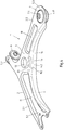
- control arm (wishbone) 1 has a base body, which has a substantially L-shaped or triangular configuration. It is designed as a front axle control arm for a motor vehicle, in particular a passenger vehicle.
- the main body 2 of the chassis link 1 is designed as a single-shell (one-piece) sheet metal part. It is formed from a sheet metal plate to the shell, in particular by deep drawing.
- the base body 2 has two arms 2.1, 2.2 merging into one another, which define a base body plane 3 and a concave edge region 4.
- main body 2 storage areas 5.1, 5.2, 5.3 are designed for connection of bearing elements.
- One of the bearing elements is a collar bushing 6, which is welded to the bearing area 5.2 and a rubber-jacketed bushing (not shown).
- a bearing pin (not shown) is mounted, which is typically designed as a ball joint.
- the designed as a bearing eye bearing area 5.3 serves to receive a rubber body 7, which encloses a bearing bush (collar bushing) 7.1 form-fitting and cohesive.
- the bearing eye 5.3 has a circumferential collar (draft) 5.31.
- the concave edge region 4 of the base body 2 extends from the wheel-side bearing region 5.1 to a body-side bearing region 5.3 and is angled relative to the base body plane 3.
- the edge regions 8, 9 of the arms 2.1, 2.2 which are opposite the concave edge region 4 are likewise angled, specifically approximately or almost in the same direction as the concave-shaped edge region 4, so that the arms 2.1, 2.2 are essentially U- or W-shaped. have a shaped cross-sectional profile.
- the main body 2 has at the respective storage area 5.1, 5.2, 5.3 an open cross-sectional shape.
- an opening 13 having a circumferential collar (passage) 13.1 can be provided in the base body plane 3 and / or in at least one of the recesses 10, 11.
- the collar 13.1, 5.31 projects from the side of the main body 2, from which the angled edge regions 4, 8, 9 protrude.
- the concave-shaped edge region 4 of the main body 2 has an inclined surface (bevel) 14, which, viewed in cross section, encloses an angle ⁇ in the region of 25 ° to 75 ° with the surface 15 adjoining it (cf. Fig. 2 ). Viewed in cross section, the surfaces 14,15 each have a substantially straight length or depth section.
- the inclined surface 14 is bounded by two radii or rounded edges R1, R2.
- the chamfer 14 extends at least along an arcuate portion of the angled, concave edge portion 4, this arc length portion at least 10%, preferably at least 20% of the arc length of the concave edge portion 4 is.
- the inclined surface (chamfer) 14 extends almost over the entire arc length of the angled, concave edge portion 4. Only at the end of the arm 2.1, on which the wheel carrier bearing portion is formed 5.1, the angled, concave edge portion 4 of the body 2 a Arc length section without the chamfer 14 (see. Fig. 1 ).
- the angle ⁇ which the oblique surface 14 encloses with the surface 15 adjacent to it, is formed substantially constant along the arc length section or angled, concave edge region 4.
- the angle ⁇ is for example about 35 ° (see. Fig. 2 ).
- the length (depth) L of the inclined surface 14 along the arc length portion or concave edge portion 4 is formed substantially constant. At the intersection AA in Fig. 1
- the length (depth) L is about 15 mm (cf. Fig. 2 ).
- FIG. 3 shown embodiment of the chassis control arm 1 according to the invention differs from that in the Figures 1 and 2 illustrated example in that the angle ⁇ , the inclines the inclined surface 14 with the adjoining surface 15, along the arc length portion or angled, concave edge portion 4 changes.
- the angle ⁇ is for example about 35 °.
- the angle ⁇ is significantly larger. For example, it is in the range of 45 ° to 60 °.
- the angle ⁇ is smaller, where it has, for example, a value in the range of 30 ° to 40 ° at or near the end of the arm 2.2 ,
- the length (depth) L of the inclined surface 14 along the arc length portion or angled, concave edge portion 4 changes.
- the inclined surface 14 has a length L in the range of 5 mm to 20 mm.
- the length (depth) L is about 15 mm, for example.
- the length L of the inclined surface 14 in the central region 4.1 of the arc length of the edge region 4, approximately where the arms 2.1, 2.2 merge into each other or the edge region 4 has its shortest distance to the passage opening 13, significantly larger. For example, it is between 16 mm and 20 mm.
- the length (depth) L of the chamfer 14 decreases, wherein it has, for example, a value between 5 mm and 15 mm at or near the end of the arm 2.2.
- suspension arms 1 are thus the angle ⁇ and the length (depth) L of the inclined surface (chamfer) 14 of the angled, concave edge portion 4 in the central region 4.1 of the handlebar 1 significantly larger than at the free ends of his arms 2.1, 2.2.
- FIG. 4 shown embodiment of the chassis control arm 1 according to the invention differs from that in the Figures 1 and 2 Example shown by the fact that the inclined surface (chamfer) 14 extends over a significantly shorter length of the arc length of the angled, concave edge portion 4 than in the in the FIGS. 1 to 3 shown suspension arms.
- the chamfer 14 extends essentially along an arc length section 4.2, which lies close to the opening 13 or between the mutually facing ends of the depressions 10, 11 of the base body 2.
- the arms 2.1, 2.2 of the control arm 1 are in this arc length section 4.2 into each other.
- the angle ⁇ and the length (depth) L of the inclined surface 14 change little or only over the course of the surface 14.
- Fig. 5 shown embodiment of the suspension arm according to the invention differs from that in the Figures 1 and 2 illustrated example in that the inclined surface 14 extends over a significantly shorter length of the arc length of the angled, concave edge portion 4 than the suspension arm according to the Figures 1 and 2 ,
- the chamfer 14 extends in this case substantially along an arc length section 4.3, which is located near the opening 13 (or middle of the handlebar) and adjacent to a longitudinal section of the recess 11 of the arm 2.1.
- the angle ⁇ and the length (depth) L of the inclined surface 14 change little or only over the course of the surface 14.
- a suspension link 1 according to the invention along an arcuate section of the angled, concave edge region 4 may also have two or more successive inclined surfaces (chamfers) 14, each viewed in cross section with an adjacent surface 15 of the angled, concave edge region 4 an angle in Range from 25 ° to 75 °.
Description
Die Erfindung betrifft einen Fahrwerkslenker mit einem einschaligen Grundkörper aus Blech, an dem mehrere Lagerbereiche zur Anbindung von Lagerelementen ausgebildet sind, mit denen der Grundkörper mit der Karosserie und einem beweglichen Teil einer Radaufhängung eines Kraftfahrzeuges verbindbar ist, wobei der Grundkörper zwei ineinander übergehende Arme aufweist, die eine Grundkörperebene und einen konkavförmigen Randbereich des Grundkörpers definieren, wobei sich der konkavförmige Randbereich von einem radseitigen Lagerbereich bis zu einem karosserieseitigen Lagerbereich erstreckt und relativ zu der Grundkörperebene abgewinkelt ist.The invention relates to a suspension link with a single-shell body made of sheet metal, on which a plurality of bearing areas are formed for connecting bearing elements, with which the base body with the body and a movable part of a suspension of a motor vehicle is connectable, wherein the main body has two arms merging into each other, which define a base body plane and a concave edge region of the base body, wherein the concave edge region extends from a wheel-side bearing region to a body-side bearing region and is angled relative to the base body plane.
Fahrwerkslenker, die ein Bindeglied zwischen der Karosserie eines Kraftfahrzeuges und einem dynamisch beweglichen Teil einer Radaufhängung, insbesondere einem Radträger bilden, sind in verschiedenen Ausführungen bekannt. Sie können als gegossene Bauteile oder als Schalen aus Stahlblech ausgebildet sein. Bei einem solchen Fahrwerkslenker kommt es neben seiner Formsteifigkeit und Verschleißbeständigkeit auch auf sein Gewicht an. Denn durch ein geringes Bauteilgewicht bei hoher Formsteifigkeit lassen sich eine Reduzierung des Fahrzeuggewichts und damit eine Verringerung des Kraftstoffverbrauchs erreichen.Suspension link, which form a link between the body of a motor vehicle and a dynamically moving part of a suspension, in particular a wheel, are known in various designs. They can be designed as cast components or as shells made of sheet steel. In such a suspension link it comes next to its stiffness and wear resistance also on its weight. Because of a low component weight with high stiffness can be a reduction in vehicle weight and thus achieve a reduction in fuel consumption.
Ein bekannter Fahrwerkslenker der eingangs genannten Art (
Die
Aus der
Der vorliegenden Erfindung lag die Aufgabe zugrunde, einen Fahrwerkslenker zu schaffen, der sich kostengünstig herstellen lässt und bei hoher Formsteifigkeit (Bauteilsteifigkeit) ein geringes Gewicht aufweist.The present invention has for its object to provide a suspension arm, which can be produced inexpensively and with high stiffness (component stiffness) has a low weight.
Diese Aufgabe wird erfindungsgemäß durch einen Fahrwerkslenker mit den Merkmalen des Anspruchs 1 gelöst. Bevorzugte und vorteilhafte Ausgestaltungen des erfindungsgemäßen Fahrwerkslenkers sind in den Unteransprüchen angegeben.This object is achieved by a suspension arm with the features of
Der erfindungsgemäße Fahrwerkslenker ist dadurch gekennzeichnet, dass der abgewinkelte, konkavförmige Randbereich seines Grundkörpers zumindest entlang eines Bogenlängenabschnitts mindestens eine schräge Fläche aufweist, die einer Fase entspricht und im Querschnitt betrachtet mit einer an sie angrenzenden Fläche des abgewinkelten, konkavförmigen Randbereichs einen Winkel im Bereich von 25° bis 75° einschließt, wobei der Bogenlängenabschnitt mindestens 10%, vorzugsweise mindestens 20% der Bogenlänge des abgewinkelten, konkavförmigen Randbereichs beträgt, und wobei die schräge Fläche im Querschnitt betrachtet eine Länge im Bereich von 5 mm bis 20 mm aufweist.The chassis control arm according to the invention is characterized in that the angled, concave edge portion of its base body at least along an arc length portion has at least one inclined surface corresponding to a chamfer and viewed in cross section with an adjacent thereto surface of the angled, concave edge portion an angle in the range of 25 ° to 75 °, wherein the arc length portion is at least 10%, preferably at least 20% of the arc length of the angled, concave edge region, and wherein the oblique surface viewed in cross section has a length in the range of 5 mm to 20 mm.
Hierdurch wird bei vorgegebener oder beibehaltener Blechdicke bzw. konstantem Bauteilgewicht die Formsteifigkeit, insbesondere die zulässige Knicklast des Fahrwerkslenkers erhöht. Des Weiteren ergibt sich durch die erfindungsgemäße Lösung eine gleichmäßigere Spannungsverteilung in dem Lenker im Fahrbetrieb. Auch lässt sich der Fahrwerkslenker aufgrund der einschaligen Blechbauweise kostengünstig herstellen; dies gilt insbesondere auch für das Formen der schrägen Fläche.As a result, the dimensional stability, in particular the permissible buckling load of the suspension arm is increased for a given or maintained sheet thickness or constant component weight. Furthermore, results from the solution according to the invention a more even stress distribution in the handlebar while driving. Also, the suspension arm can be produced inexpensively due to the single-shell sheet metal construction; this applies in particular to the shaping of the inclined surface.
Die an dem abgewinkelten, konkavförmigen Randbereich des Grundkörpers ausgebildete schräge Fläche entspricht einer Fase. Sie kann entlang der gesamten Bogenlänge des abgewinkelten, konkavförmigen Randbereichs des Grundkörpers ausgebildet sein. Zur Erhöhung der Bauteilsteifigkeit, insbesondere Knicklast, und/oder zur Vergleichmäßigung der Spannungsverteilung in dem Grundkörper kann es allerdings auch ausreichen, wenn sich die schräge Fläche (Fase) nur über eine Teillänge der Bogenlänge des abgewinkelten, konkavförmigen Randbereichs erstreckt, beispielsweise über weniger als 80%, insbesondere weniger als 60% dieser Bogenlänge erstreckt. Die Erfindung sieht ferner vor, dass der Bogenlängenabschnitt, über den sich die schräge Fläche erstreckt, mindestens 10%, vorzugsweise mindestens 20% der Bogenlänge des abgewinkelten, konkavförmigen Randbereichs beträgt. Dadurch, dass erfindungsgemäß zudem die schräge Fläche im Querschnitt betrachtet eine Länge im Bereich von 5 mm bis 20 mm aufweist, ist die Bauteilsteifigkeit bzw. aufnehmbare Knicklast des Fahrwerkslenkers deutlich erhöht.The oblique surface formed on the angled, concave-shaped edge region of the base body corresponds to a chamfer. It can be formed along the entire arc length of the angled, concave edge region of the base body. However, to increase the component rigidity, in particular buckling load, and / or to even out the stress distribution in the base body, it may also be sufficient if the inclined surface (chamfer) extends over only a partial length of the arc length of the angled, concave edge region, for example less than 80 %, in particular less than 60% of this arc length extends. The invention further provides that the arcuate section over which the oblique surface extends, at least 10%, preferably at least 20% of the arc length of the angled, concave edge portion. Due to the fact that according to the invention, moreover, the oblique surface viewed in cross-section has a length in the range of 5 mm to 20 mm, the component rigidity or absorbable buckling load of the suspension link is significantly increased.
Eine vorteilhafte Ausgestaltung des erfindungsgemäßen Fahrwerkslenkers ist dadurch gekennzeichnet, dass sich der Winkel, den die schräge Fläche mit der an sie angrenzenden Fläche des abgewinkelten, konkaven Randbereichs einschließt, entlang des Bogenlängenabschnitts ändert, wobei die Änderung mindestens 5°, vorzugsweise mindestens 10° beträgt. Hierdurch kann die Bauteilsteifigkeit, insbesondere die zulässige Knicklast weiter erhöht werden. Auch kann durch diese Ausgestaltung die im Grundkörper des Fahrwerkslenkers während des Fahrbetriebes auftretende Spannungsverteilung weiter vergleichmäßig bzw. optimiert werden.An advantageous embodiment of the suspension control arm according to the invention is characterized in that the angle which the oblique surface encloses with the adjoining surface of the angled, concave edge region, changes along the arc length portion, wherein the change is at least 5 °, preferably at least 10 °. As a result, the component rigidity, in particular the permissible buckling load, can be further increased. Also, by this configuration, the voltage distribution occurring in the body of the suspension control arm during driving operation can be further uniformized or optimized.
Zudem wurde gefunden, dass die Bauteilsteifigkeit, die aufnehmbare Knicklast des Fahrwerkslenkers und/oder die Spannungsverteilung weiter optimiert werden, wenn gemäß einer bevorzugten Ausgestaltung der Erfindung sich die Länge der schrägen Fläche entlang des Bogenlängenabschnitts ändert, wobei die Änderung mindestens 1 mm, insbesondere mindestens 2 mm beträgt.In addition, it has been found that the component rigidity, the absorbable buckling load of the suspension control arm and / or the stress distribution are further optimized if, according to a preferred embodiment of the invention, the length of the inclined surface changes along the arc length section, the change being at least 1 mm, in particular at least 2 mm.
Besonders bevorzugt ist eine Ausführungsform des erfindungsgemäßen Fahrwerkslenkers, bei welcher der die schräge Fläche aufweisende Bogenlängenabschnitt den Grundkörperbereich kreuzt, in welchem die beiden Arme ineinander übergehen. Diese Ausgestaltung ist hinsichtlich der angestrebten Erhöhung der Bauteilsteifigkeit und der Vergleichmäßigung der Spannungsverteilung besonders effektiv.Particularly preferred is an embodiment of the chassis control arm according to the invention, in which the oblique surface having arc length section crosses the body region in which the two arms merge into each other. These Embodiment is particularly effective in terms of the desired increase in component rigidity and the homogenization of the stress distribution.
Hinsichtlich einer Vergleichmäßigung der Spannungsverteilung ist es günstig, wenn nach einer weiteren bevorzugten Ausgestaltung des erfindungsgemäßen Fahrwerkslenkers dessen Grundkörperebene mit einer runden Kante in die schräge Fläche (Fase) übergeht. Vorzugsweise besitzt diese runde Kante einen Radius (Außenradius), der größer als die Blechdicke des Grundkörpers ist, beispielsweise das 1,5-fache bis 3-fache der Blechdicke beträgt.With regard to a homogenization of the stress distribution, it is favorable if, according to a further preferred embodiment of the suspension control arm according to the invention, its basic body plane merges with a round edge into the inclined surface (chamfer). Preferably, this round edge has a radius (outer radius), which is greater than the sheet thickness of the base body, for example, is 1.5 times to 3 times the sheet thickness.
Auch ist es zur Vergleichmäßigung der Spannungsverteilung günstig, wenn nach einer weiteren bevorzugten Ausgestaltung des erfindungsgemäßen Fahrwerkslenkers dessen schräge Fläche mit einer runden Kante in die an sie angrenzende Fläche des abgewinkelten, konkavförmigen Randbereichs übergeht. Vorzugsweise besitzt diese runde Kante einen Radius (Außenradius), der ebenfalls größer als die Blechdicke des Grundkörpers ist, beispielsweise das 1,5-fache bis 3-fache der Blechdicke beträgt.Also, it is favorable to even out the stress distribution, if, according to a further preferred embodiment of the suspension control arm according to the invention the inclined surface merges with a round edge in the adjoining surface of the angled, concave edge region. Preferably, this round edge has a radius (outer radius), which is also greater than the sheet thickness of the base body, for example, is 1.5 times to 3 times the sheet thickness.
Die Herstellungskosten eines erfindungsgemäßen Fahrwerkslenkers sind insbesondere dann vergleichsweise niedrig, wenn gemäß einer bevorzugten Ausführungsform der Grundkörper des Fahrwerkslenkers an dem jeweiligen Lagerbereich eine offene Querschnittsform aufweist.The manufacturing costs of a suspension control arm according to the invention are comparatively low in particular if, according to a preferred embodiment, the main body of the suspension control arm has an open cross-sectional shape at the respective storage area.
Um ein möglichst geringes Gewicht bei hoher Bauteilsteifigkeit zu erzielen, sollte das Blech des Grundkörpers eine Dicke im Bereich von 2 mm bis 6 mm und eine Zugfestigkeit im Bereich von 350 MPa bis 1.200 MPa haben. Vorzugsweise sollte der Grundkörper aus Dualphasenstahl bestehen. Auch sogenannte Complexphasenstähle oder thermomechanisch gewalzte Kaltformstähle sind zur Herstellung des erfindungsgemäßen Fahrwerkslenkers gut geeignet, wenn höhere Festigkeiten bzw. Bauteilsteifigkeiten gewünscht werden.In order to achieve the lowest possible weight with high component stiffness, the sheet of the main body should have a thickness in the range of 2 mm to 6 mm and a tensile strength in the range of 350 MPa to 1200 MPa. Preferably, the base body should consist of dual-phase steel. Also so-called complex-phase steels or thermomechanically rolled cold-forming steels are well suited for the production of the suspension control arm according to the invention, if higher strengths or component stiffnesses are desired.
Nachfolgend wird die Erfindung anhand einer mehrere Ausführungsbeispiele darstellenden Zeichnung näher erläutert. Es zeigen:
- Fig. 1
- einen aus Blech geformten einschaligen Fahrwerkslenker in Draufsicht;
- Fig. 2
- eine vergrößerte Querschnittansicht eines Arms des Fahrwerkslenkers entlang der Schnittlinie A-A in
Fig. 1 ; - Fig. 3
- eine zweite Ausführungsform eines aus Blech geformten einschaligen Fahrwerkslenkers in perspektivischer Ansicht;
- Fig. 4
- eine dritte Ausführungsform eines aus Blech geformten einschaligen Fahrwerkslenkers in perspektivischer Ansicht; und
- Fig. 5
- eine vierte Ausführungsform eines aus Blech geformten einschaligen Fahrwerkslenkers in perspektivischer Ansicht.
- Fig. 1
- a sheet-formed single-shell suspension arm in plan view;
- Fig. 2
- an enlarged cross-sectional view of an arm of the suspension arm along the section line AA in
Fig. 1 ; - Fig. 3
- a second embodiment of a molded sheet metal single-shell suspension arm in perspective view;
- Fig. 4
- a third embodiment of a molded sheet metal single-shell suspension arm in perspective view; and
- Fig. 5
- a fourth embodiment of a molded sheet metal single-leaf suspension arm in a perspective view.
Der in den
Der Grundkörper 2 des Fahrwerkslenkers 1 ist als einschaliges (einstückiges) Blechformteil gestaltet. Er ist aus einer Blechplatine zu der Schale umgeformt, insbesondere durch Tiefziehen. Der Grundkörper 2 weist zwei ineinander übergehende Arme 2.1, 2.2 auf, die eine Grundkörperebene 3 und einen konkavförmigen Randbereich 4 definieren.The
An dem Grundkörper 2 sind Lagerbereiche 5.1, 5.2, 5.3 zur Anbindung von Lagerelementen ausgebildet. Eines der Lagerelemente ist eine Bundbuchse 6, die an dem Lagerbereich 5.2 angeschweißt wird und eine gummiummantelte Lagerbuchse (nicht gezeigt) aufnimmt. An dem radseitigen Lagerbereich 5.1 wird ein Lagerzapfen (nicht gezeigt) montiert, der typischerweise als Kugelgelenk ausgebildet ist. Der als Lagerauge ausgebildete Lagerbereich 5.3 dient der Aufnahme eines Gummikörpers 7, der eine Lagerbuchse (Bundbuchse) 7.1 form- und stoffschlüssig umschließt. Das Lagerauge 5.3 weist einen umlaufenden Kragen (Durchzug) 5.31 auf.On the
Der konkavförmige Randbereich 4 des Grundkörpers 2 erstreckt sich von dem radseitigen Lagerbereich 5.1 bis zu einem karosserieseitigen Lagerbereich 5.3 und ist relativ zu der Grundkörperebene 3 abgewinkelt. Die dem konkaven Randbereich 4 gegenüberliegenden Randbereiche 8, 9 der Arme 2.1, 2.2 sind ebenfalls abgewinkelt, und zwar in etwa oder nahezu in die gleiche Richtung wie der konkavförmige Randbereich 4, so dass die Arme 2.1, 2.2 ein im Wesentlichen U- oder W-förmiges Querschnittsprofil haben. Der Grundkörper 2 weist an dem jeweiligen Lagerbereich 5.1, 5.2, 5.3 eine offene Querschnittsform auf.The
In die Grundkörperebene 3 sind Sicken oder Vertiefungen 10, 11 eingeformt. Des Weiteren können in der Grundkörperebene 3 und/oder in mindestens einer der Vertiefungen 10, 11 Durchgangslöcher, beispielsweise eine einen umlaufenden Kragen (Durchzug) 13.1 aufweisende Öffnung 13 vorgesehen sein. Der Kragen 13.1, 5.31 steht dabei von der Seite des Grundkörpers 2 ab, von der auch die abgewinkelten Randbereiche 4, 8, 9 vorstehen.In the
Der konkavförmige Randbereich 4 des Grundkörpers 2 hat eine schräge Fläche (Fase) 14, die im Querschnitt betrachtet mit der an sie angrenzenden Fläche 15 einen Winkel α im Bereich von 25° bis 75° einschließt (vgl.
Die Fase 14 erstreckt sich zumindest entlang eines Bogenlängenabschnitts des abgewinkelten, konkaven Randbereichs 4, wobei dieser Bogenlängenabschnitt mindestens 10%, vorzugsweise mindestens 20% der Bogenlänge des konkaven Randbereichs 4 beträgt.The
Bei dem in den
Der Winkel α, den die schräge Fläche 14 mit der an sie angrenzenden Fläche 15 einschließt, ist entlang des Bogenlängenabschnitts bzw. abgewinkelten, konkaven Randbereichs 4 im Wesentlichen konstant ausgebildet. Der Winkel α beträgt beispielsweise ca. 35°(vgl.
Das in
Ferner ist in
Bei dem in
Das in
Auch das weitere, in
Die Ausführung der Erfindung ist nicht auf die in der Zeichnung dargestellten Ausführungsbeispiele beschränkt. Vielmehr sind zahlreiche Varianten denkbar, die auch bei von diesen Beispielen abweichender Gestaltung von der in den beiliegenden Ansprüchen angegebenen Erfindung Gebrauch machen. Beispielsweise kann ein erfindungsgemäßer Fahrwerkslenker 1 entlang eines Bogenlängenabschnitts des abgewinkelten, konkavförmigen Randbereichs 4 auch zwei oder mehr aufeinander folgende schräge Flächen (Fasen) 14 aufweisen, die jeweils im Querschnitt betrachtet mit einer an sie angrenzenden Fläche 15 des abgewinkelten, konkavförmigen Randbereichs 4 einen Winkel im Bereich von 25° bis 75° einschließen.The embodiment of the invention is not limited to the embodiments shown in the drawing. On the contrary, numerous variants are conceivable which make use of the invention specified in the appended claims, even if the design deviates from these examples. For example, a
Claims (9)
- Chassis link (1) comprising a single-shell sheet metal main body (2), on which a plurality of bearing regions (5.1, 5.2, 5.3) are formed for attaching bearing elements by which the main body (2) can be connected to the bodywork and to a movable part of a wheel suspension of a motor vehicle, the main body (2) comprising two arms (2.1, 2.2) which merge into one another and define a main-body plane (3) and a concave edge region (4) of the main body, the concave edge region (4) extending from a wheel-side bearing region (5.1) towards a bodywork-side bearing region (5.3) and being at an angle relative to the main-body plane (3), characterised in that the angled, concave edge region (4) comprises, along at least one curve length portion (4.2, 4.3), at least one oblique surface (14) which corresponds to a chamfer and, when viewed in cross section, forms an angle (α) in the range of from 25° to 75° with a surface (15), adjacent thereto, of the angled, concave edge region, wherein the curve length portion (4.2, 4.3) is at least 10 %, preferably at least 20 %, of the curve length of the angled, concave edge region (4), and wherein, when viewed in cross section, the oblique surface (14) has a length (L) in the range of from 5 mm to 20 mm.
- Chassis link according to claim 1, characterised in that the angle (α) formed by the oblique surface (14) and a surface (15), adjacent thereto, of the angled, concave edge region (4) varies along the curve length portion, the variation being at least 5°, preferably at least 10°.
- Chassis link according to either claim 1 or claim 2, characterised in that the length (L) of the oblique surface (14) varies along the curve length portion, the variation being at least 1 mm, in particular at least 2 mm.
- Chassis link according to any of claims 1 to 3, characterised in that the curve length portion (4.2,4.3) having the oblique surface (14) crosses the region of the main body in which the two arms (2.1, 2.2) merge into one another.
- Chassis link according to any of claims 1 to 4, characterised in that the main-body plane (3) merges, with a round edge (R1), into the oblique surface (14).
- Chassis link according to any of claims 1 to 5, characterised in that the oblique surface (14) merges, with a round edge (R2), into the surface (15), adjacent thereto, of the angled, concave edge region (4).
- Chassis link according to any of claims 1 to 6, characterised in that the main body (2) has an open cross-sectional shape at each bearing region (5.1, 5.2, 5.3).
- Chassis link according to any of claims 1 to 7, characterised in that the sheet has a thickness is the range of from 2 mm to 6 mm and a tensile strength in the range of from 350 MPa to 1200 MPa.
- Chassis link according to any of claims 1 to 8, characterised in that the main body (2) consists of dual-phase steel, complex phase steel or thermomechanically rolled, cold-formed steel.
Priority Applications (3)
| Application Number | Priority Date | Filing Date | Title |
|---|---|---|---|
| EP14159165.1A EP2918430B1 (en) | 2014-03-12 | 2014-03-12 | Suspension arm for a motor vehicle |
| CN201510106694.1A CN104908542B (en) | 2014-03-12 | 2015-03-11 | The chassis steering arm of motor vehicle |
| US14/644,660 US9561699B2 (en) | 2014-03-12 | 2015-03-11 | Chassis link for a motor vehicle |
Applications Claiming Priority (1)
| Application Number | Priority Date | Filing Date | Title |
|---|---|---|---|
| EP14159165.1A EP2918430B1 (en) | 2014-03-12 | 2014-03-12 | Suspension arm for a motor vehicle |
Publications (2)
| Publication Number | Publication Date |
|---|---|
| EP2918430A1 EP2918430A1 (en) | 2015-09-16 |
| EP2918430B1 true EP2918430B1 (en) | 2017-05-03 |
Family
ID=50241236
Family Applications (1)
| Application Number | Title | Priority Date | Filing Date |
|---|---|---|---|
| EP14159165.1A Active EP2918430B1 (en) | 2014-03-12 | 2014-03-12 | Suspension arm for a motor vehicle |
Country Status (3)
| Country | Link |
|---|---|
| US (1) | US9561699B2 (en) |
| EP (1) | EP2918430B1 (en) |
| CN (1) | CN104908542B (en) |
Families Citing this family (7)
| Publication number | Priority date | Publication date | Assignee | Title |
|---|---|---|---|---|
| FR2993806B1 (en) * | 2012-07-26 | 2015-02-13 | Saint Jean Ind | PROCESS FOR MANUFACTURING STRUCTURE PARTS OF LIGHT ALLOY AND PARTS THUS OBTAINED FOR OPTIMIZING THE MASS / PERFORMANCE RATIO |
| JP5771320B2 (en) * | 2013-12-19 | 2015-08-26 | 株式会社神戸製鋼所 | Automobile undercarriage parts |
| MX2016013290A (en) * | 2014-04-11 | 2017-01-18 | Nippon Steel & Sumitomo Metal Corp | Press-moulded article manufacturing method and vehicle lower arm. |
| DE102014220796A1 (en) * | 2014-10-14 | 2016-04-14 | Zf Friedrichshafen Ag | Articulated rod for a motor vehicle |
| JP6360623B2 (en) * | 2015-04-13 | 2018-07-18 | 株式会社エフテック | Vehicle suspension arm |
| FR3042444B1 (en) * | 2015-10-16 | 2017-11-03 | Renault Sas | SUSPENSION ARM HAVING DIFFERENT THICKNESSES |
| EP3865322B1 (en) | 2020-02-12 | 2023-08-23 | Gestamp Servicios, S.A. | Chassis component |
Family Cites Families (17)
| Publication number | Priority date | Publication date | Assignee | Title |
|---|---|---|---|---|
| US4570968A (en) * | 1982-12-06 | 1986-02-18 | Mazda Motor Corporation | Vehicle suspension system |
| JP3505899B2 (en) * | 1996-03-04 | 2004-03-15 | トヨタ自動車株式会社 | Vehicle suspension arm |
| FR2864514B1 (en) * | 2003-12-29 | 2007-02-23 | Auto Chassis Int Snc | SHEET BONDING MEMBER FOR WELDING WITH AN ELEMENT COMPRISING A BURST SURFACE, METHOD OF MANUFACTURE, BINDING MATRIX AND VEHICLE THEREFOR |
| DE202005011340U1 (en) * | 2005-07-15 | 2005-09-22 | GEDIA Gebrüder Dingerkus GmbH | Wishbone of especially light metal for running gear of vehicle has first upper flat sheet bar, with at least one edge profiled in fashion of channel, with additional channel profile seated on aforesaid channel |
| DE102007018569B4 (en) | 2007-04-18 | 2014-07-17 | Gmf Umformtechnik Gmbh | Suspension handlebar for a motor vehicle |
| EP2295269B1 (en) * | 2008-07-10 | 2012-09-05 | Honda Motor Co., Ltd. | Suspension arm for vehicle |
| IT1390790B1 (en) * | 2008-07-11 | 2011-10-19 | Tiberina Solutions S R L | METHOD FOR MOLDING AN ARM FOR AUTOMOTIVE SUSPENSIONS |
| IT1398384B1 (en) * | 2009-02-05 | 2013-02-22 | Sistemi Sospensioni Spa | OSCILLATING ARM FOR VEHICLE SUSPENSION AND PROCEDURE FOR ITS REALIZATION |
| DE102009041478A1 (en) * | 2009-09-14 | 2011-03-31 | Magna Presstec Ag | Component, in particular handlebar for a vehicle |
| DE102010007946A1 (en) * | 2010-02-12 | 2011-08-18 | Benteler Automobiltechnik GmbH, 33102 | Wishbone with bearing pin and method for producing a control arm |
| DE102010024634A1 (en) * | 2010-06-22 | 2011-12-22 | Benteler Automobiltechnik Gmbh | Motor vehicle drivers |
| CN104066602B (en) * | 2011-12-21 | 2016-08-24 | 本田技研工业株式会社 | Suspension link installation constitution |
| FR2991611B1 (en) * | 2012-06-11 | 2014-12-19 | Peugeot Citroen Automobiles Sa | ARM FOR SUSPENSION OF A WHEEL TO THE BODY OF A MOTOR VEHICLE WITH CONTINUOUS REINFORCEMENT |
| CN203293836U (en) * | 2013-05-16 | 2013-11-20 | 上海通用汽车有限公司 | Suspension control arm |
| ES2675327T3 (en) * | 2014-04-02 | 2018-07-10 | Autotech Engineering Deutschland GmbH | Procedure for manufacturing a undercarriage arm |
| DE102014107953A1 (en) * | 2014-06-05 | 2015-12-17 | Benteler Automobiltechnik Gmbh | Built wheel carrier |
| JP6488598B2 (en) * | 2014-09-05 | 2019-03-27 | スズキ株式会社 | Suspension frame structure |
-
2014
- 2014-03-12 EP EP14159165.1A patent/EP2918430B1/en active Active
-
2015
- 2015-03-11 CN CN201510106694.1A patent/CN104908542B/en active Active
- 2015-03-11 US US14/644,660 patent/US9561699B2/en active Active
Also Published As
| Publication number | Publication date |
|---|---|
| US20150258869A1 (en) | 2015-09-17 |
| EP2918430A1 (en) | 2015-09-16 |
| US9561699B2 (en) | 2017-02-07 |
| CN104908542B (en) | 2017-08-18 |
| CN104908542A (en) | 2015-09-16 |
Similar Documents
| Publication | Publication Date | Title |
|---|---|---|
| EP2918430B1 (en) | Suspension arm for a motor vehicle | |
| EP2809531B1 (en) | Single shell spring link | |
| EP2927029B1 (en) | Method for producing a suspension arm | |
| EP2670611B1 (en) | One-shell suspension arm | |
| DE102010010665B4 (en) | Stabilizing strut for a chassis of a vehicle | |
| DE102009050058C5 (en) | Twist-beam axle and method for producing composite beam axles for motor vehicles | |
| DE102010010456B4 (en) | Spring support and mounting structure for spring support | |
| EP3124362B1 (en) | Subframe, in particular rear axle subframe, for a passenger vehicle | |
| EP2910454B1 (en) | Undercarriage component with eccentric disc stop | |
| EP3192680A1 (en) | Suspension arm of steel comprising a spring seat | |
| DE102007058582A1 (en) | Torsion carrier of a suspension | |
| DE102019108548B4 (en) | Spring handlebars | |
| EP3530497A1 (en) | Undercarriage component with eccentric disc stop and method for producing an undercarriage component | |
| EP2697083A1 (en) | Pivot bearing | |
| EP3498504B1 (en) | Suspension arm for a wheel suspension of a motor vehicle | |
| DE10336800B4 (en) | Twist-beam axle for a motor vehicle | |
| EP2055511A1 (en) | Twist beam axle | |
| DE102004009722A1 (en) | Transverse control arm for use in vehicle suspensions has two or more sections with bearings at their ends, arm being made from sheet metal and sections having flanges along their edges which give it asymmetric cross-section | |
| DE102006011107B3 (en) | Transverse link of wheel suspension has embossing, deployed in direction opposite to side bars with univalve configured in u-shaped cross section, and shell body has arms and base section to whose outer edge angular lateral bar is attached | |
| DE102014218323B4 (en) | Axle unit | |
| DE102014205990A1 (en) | Articulated connection for transmitting a steering movement to a wheel of a vehicle | |
| DE102014215871A1 (en) | Vehicle axle with a transversely extending in the vehicle transverse direction and wheel guiding transverse leaf spring | |
| DE19846400B4 (en) | Torsion beam rear axle | |
| EP3539802B1 (en) | Transverse arm with shell construction for a wheel suspension | |
| DE10011845A1 (en) | Wheel suspension connecting rod in dish form has third dish component inserted between first two dish components |
Legal Events
| Date | Code | Title | Description |
|---|---|---|---|
| PUAI | Public reference made under article 153(3) epc to a published international application that has entered the european phase |
Free format text: ORIGINAL CODE: 0009012 |
|
| AK | Designated contracting states |
Kind code of ref document: A1 Designated state(s): AL AT BE BG CH CY CZ DE DK EE ES FI FR GB GR HR HU IE IS IT LI LT LU LV MC MK MT NL NO PL PT RO RS SE SI SK SM TR |
|
| AX | Request for extension of the european patent |
Extension state: BA ME |
|
| 17P | Request for examination filed |
Effective date: 20151001 |
|
| RBV | Designated contracting states (corrected) |
Designated state(s): AL AT BE BG CH CY CZ DE DK EE ES FI FR GB GR HR HU IE IS IT LI LT LU LV MC MK MT NL NO PL PT RO RS SE SI SK SM TR |
|
| RIC1 | Information provided on ipc code assigned before grant |
Ipc: B60G 3/06 20060101ALI20160929BHEP Ipc: B60G 7/00 20060101AFI20160929BHEP |
|
| GRAP | Despatch of communication of intention to grant a patent |
Free format text: ORIGINAL CODE: EPIDOSNIGR1 |
|
| INTG | Intention to grant announced |
Effective date: 20161117 |
|
| GRAS | Grant fee paid |
Free format text: ORIGINAL CODE: EPIDOSNIGR3 |
|
| GRAA | (expected) grant |
Free format text: ORIGINAL CODE: 0009210 |
|
| AK | Designated contracting states |
Kind code of ref document: B1 Designated state(s): AL AT BE BG CH CY CZ DE DK EE ES FI FR GB GR HR HU IE IS IT LI LT LU LV MC MK MT NL NO PL PT RO RS SE SI SK SM TR |
|
| REG | Reference to a national code |
Ref country code: GB Ref legal event code: FG4D Free format text: NOT ENGLISH |
|
| REG | Reference to a national code |
Ref country code: AT Ref legal event code: REF Ref document number: 889555 Country of ref document: AT Kind code of ref document: T Effective date: 20170515 Ref country code: CH Ref legal event code: EP |
|
| REG | Reference to a national code |
Ref country code: IE Ref legal event code: FG4D Free format text: LANGUAGE OF EP DOCUMENT: GERMAN |
|
| REG | Reference to a national code |
Ref country code: DE Ref legal event code: R096 Ref document number: 502014003601 Country of ref document: DE |
|
| REG | Reference to a national code |
Ref country code: NL Ref legal event code: MP Effective date: 20170503 |
|
| REG | Reference to a national code |
Ref country code: LT Ref legal event code: MG4D |
|
| PG25 | Lapsed in a contracting state [announced via postgrant information from national office to epo] |
Ref country code: NO Free format text: LAPSE BECAUSE OF FAILURE TO SUBMIT A TRANSLATION OF THE DESCRIPTION OR TO PAY THE FEE WITHIN THE PRESCRIBED TIME-LIMIT Effective date: 20170803 Ref country code: LT Free format text: LAPSE BECAUSE OF FAILURE TO SUBMIT A TRANSLATION OF THE DESCRIPTION OR TO PAY THE FEE WITHIN THE PRESCRIBED TIME-LIMIT Effective date: 20170503 Ref country code: HR Free format text: LAPSE BECAUSE OF FAILURE TO SUBMIT A TRANSLATION OF THE DESCRIPTION OR TO PAY THE FEE WITHIN THE PRESCRIBED TIME-LIMIT Effective date: 20170503 Ref country code: ES Free format text: LAPSE BECAUSE OF FAILURE TO SUBMIT A TRANSLATION OF THE DESCRIPTION OR TO PAY THE FEE WITHIN THE PRESCRIBED TIME-LIMIT Effective date: 20170503 Ref country code: GR Free format text: LAPSE BECAUSE OF FAILURE TO SUBMIT A TRANSLATION OF THE DESCRIPTION OR TO PAY THE FEE WITHIN THE PRESCRIBED TIME-LIMIT Effective date: 20170804 Ref country code: FI Free format text: LAPSE BECAUSE OF FAILURE TO SUBMIT A TRANSLATION OF THE DESCRIPTION OR TO PAY THE FEE WITHIN THE PRESCRIBED TIME-LIMIT Effective date: 20170503 |
|
| PG25 | Lapsed in a contracting state [announced via postgrant information from national office to epo] |
Ref country code: IS Free format text: LAPSE BECAUSE OF FAILURE TO SUBMIT A TRANSLATION OF THE DESCRIPTION OR TO PAY THE FEE WITHIN THE PRESCRIBED TIME-LIMIT Effective date: 20170903 Ref country code: PL Free format text: LAPSE BECAUSE OF FAILURE TO SUBMIT A TRANSLATION OF THE DESCRIPTION OR TO PAY THE FEE WITHIN THE PRESCRIBED TIME-LIMIT Effective date: 20170503 Ref country code: SE Free format text: LAPSE BECAUSE OF FAILURE TO SUBMIT A TRANSLATION OF THE DESCRIPTION OR TO PAY THE FEE WITHIN THE PRESCRIBED TIME-LIMIT Effective date: 20170503 Ref country code: NL Free format text: LAPSE BECAUSE OF FAILURE TO SUBMIT A TRANSLATION OF THE DESCRIPTION OR TO PAY THE FEE WITHIN THE PRESCRIBED TIME-LIMIT Effective date: 20170503 Ref country code: RS Free format text: LAPSE BECAUSE OF FAILURE TO SUBMIT A TRANSLATION OF THE DESCRIPTION OR TO PAY THE FEE WITHIN THE PRESCRIBED TIME-LIMIT Effective date: 20170503 Ref country code: LV Free format text: LAPSE BECAUSE OF FAILURE TO SUBMIT A TRANSLATION OF THE DESCRIPTION OR TO PAY THE FEE WITHIN THE PRESCRIBED TIME-LIMIT Effective date: 20170503 Ref country code: BG Free format text: LAPSE BECAUSE OF FAILURE TO SUBMIT A TRANSLATION OF THE DESCRIPTION OR TO PAY THE FEE WITHIN THE PRESCRIBED TIME-LIMIT Effective date: 20170803 |
|
| PG25 | Lapsed in a contracting state [announced via postgrant information from national office to epo] |
Ref country code: CZ Free format text: LAPSE BECAUSE OF FAILURE TO SUBMIT A TRANSLATION OF THE DESCRIPTION OR TO PAY THE FEE WITHIN THE PRESCRIBED TIME-LIMIT Effective date: 20170503 Ref country code: SK Free format text: LAPSE BECAUSE OF FAILURE TO SUBMIT A TRANSLATION OF THE DESCRIPTION OR TO PAY THE FEE WITHIN THE PRESCRIBED TIME-LIMIT Effective date: 20170503 Ref country code: EE Free format text: LAPSE BECAUSE OF FAILURE TO SUBMIT A TRANSLATION OF THE DESCRIPTION OR TO PAY THE FEE WITHIN THE PRESCRIBED TIME-LIMIT Effective date: 20170503 Ref country code: RO Free format text: LAPSE BECAUSE OF FAILURE TO SUBMIT A TRANSLATION OF THE DESCRIPTION OR TO PAY THE FEE WITHIN THE PRESCRIBED TIME-LIMIT Effective date: 20170503 Ref country code: DK Free format text: LAPSE BECAUSE OF FAILURE TO SUBMIT A TRANSLATION OF THE DESCRIPTION OR TO PAY THE FEE WITHIN THE PRESCRIBED TIME-LIMIT Effective date: 20170503 |
|
| REG | Reference to a national code |
Ref country code: DE Ref legal event code: R097 Ref document number: 502014003601 Country of ref document: DE |
|
| PG25 | Lapsed in a contracting state [announced via postgrant information from national office to epo] |
Ref country code: IT Free format text: LAPSE BECAUSE OF FAILURE TO SUBMIT A TRANSLATION OF THE DESCRIPTION OR TO PAY THE FEE WITHIN THE PRESCRIBED TIME-LIMIT Effective date: 20170503 Ref country code: SM Free format text: LAPSE BECAUSE OF FAILURE TO SUBMIT A TRANSLATION OF THE DESCRIPTION OR TO PAY THE FEE WITHIN THE PRESCRIBED TIME-LIMIT Effective date: 20170503 |
|
| PLBE | No opposition filed within time limit |
Free format text: ORIGINAL CODE: 0009261 |
|
| STAA | Information on the status of an ep patent application or granted ep patent |
Free format text: STATUS: NO OPPOSITION FILED WITHIN TIME LIMIT |
|
| REG | Reference to a national code |
Ref country code: FR Ref legal event code: PLFP Year of fee payment: 5 |
|
| 26N | No opposition filed |
Effective date: 20180206 |
|
| PG25 | Lapsed in a contracting state [announced via postgrant information from national office to epo] |
Ref country code: SI Free format text: LAPSE BECAUSE OF FAILURE TO SUBMIT A TRANSLATION OF THE DESCRIPTION OR TO PAY THE FEE WITHIN THE PRESCRIBED TIME-LIMIT Effective date: 20170503 |
|
| PG25 | Lapsed in a contracting state [announced via postgrant information from national office to epo] |
Ref country code: MT Free format text: LAPSE BECAUSE OF FAILURE TO SUBMIT A TRANSLATION OF THE DESCRIPTION OR TO PAY THE FEE WITHIN THE PRESCRIBED TIME-LIMIT Effective date: 20170503 |
|
| REG | Reference to a national code |
Ref country code: CH Ref legal event code: PL |
|
| PG25 | Lapsed in a contracting state [announced via postgrant information from national office to epo] |
Ref country code: MC Free format text: LAPSE BECAUSE OF FAILURE TO SUBMIT A TRANSLATION OF THE DESCRIPTION OR TO PAY THE FEE WITHIN THE PRESCRIBED TIME-LIMIT Effective date: 20170503 |
|
| REG | Reference to a national code |
Ref country code: BE Ref legal event code: MM Effective date: 20180331 |
|
| REG | Reference to a national code |
Ref country code: IE Ref legal event code: MM4A |
|
| PG25 | Lapsed in a contracting state [announced via postgrant information from national office to epo] |
Ref country code: LU Free format text: LAPSE BECAUSE OF NON-PAYMENT OF DUE FEES Effective date: 20180312 |
|
| PG25 | Lapsed in a contracting state [announced via postgrant information from national office to epo] |
Ref country code: IE Free format text: LAPSE BECAUSE OF NON-PAYMENT OF DUE FEES Effective date: 20180312 |
|
| PG25 | Lapsed in a contracting state [announced via postgrant information from national office to epo] |
Ref country code: BE Free format text: LAPSE BECAUSE OF NON-PAYMENT OF DUE FEES Effective date: 20180331 Ref country code: CH Free format text: LAPSE BECAUSE OF NON-PAYMENT OF DUE FEES Effective date: 20180331 Ref country code: LI Free format text: LAPSE BECAUSE OF NON-PAYMENT OF DUE FEES Effective date: 20180331 |
|
| PG25 | Lapsed in a contracting state [announced via postgrant information from national office to epo] |
Ref country code: TR Free format text: LAPSE BECAUSE OF FAILURE TO SUBMIT A TRANSLATION OF THE DESCRIPTION OR TO PAY THE FEE WITHIN THE PRESCRIBED TIME-LIMIT Effective date: 20170503 |
|
| PG25 | Lapsed in a contracting state [announced via postgrant information from national office to epo] |
Ref country code: PT Free format text: LAPSE BECAUSE OF FAILURE TO SUBMIT A TRANSLATION OF THE DESCRIPTION OR TO PAY THE FEE WITHIN THE PRESCRIBED TIME-LIMIT Effective date: 20170503 |
|
| PG25 | Lapsed in a contracting state [announced via postgrant information from national office to epo] |
Ref country code: CY Free format text: LAPSE BECAUSE OF FAILURE TO SUBMIT A TRANSLATION OF THE DESCRIPTION OR TO PAY THE FEE WITHIN THE PRESCRIBED TIME-LIMIT Effective date: 20170503 Ref country code: MK Free format text: LAPSE BECAUSE OF NON-PAYMENT OF DUE FEES Effective date: 20170503 Ref country code: HU Free format text: LAPSE BECAUSE OF FAILURE TO SUBMIT A TRANSLATION OF THE DESCRIPTION OR TO PAY THE FEE WITHIN THE PRESCRIBED TIME-LIMIT; INVALID AB INITIO Effective date: 20140312 |
|
| PG25 | Lapsed in a contracting state [announced via postgrant information from national office to epo] |
Ref country code: AL Free format text: LAPSE BECAUSE OF FAILURE TO SUBMIT A TRANSLATION OF THE DESCRIPTION OR TO PAY THE FEE WITHIN THE PRESCRIBED TIME-LIMIT Effective date: 20170503 |
|
| REG | Reference to a national code |
Ref country code: AT Ref legal event code: MM01 Ref document number: 889555 Country of ref document: AT Kind code of ref document: T Effective date: 20190312 |
|
| PG25 | Lapsed in a contracting state [announced via postgrant information from national office to epo] |
Ref country code: AT Free format text: LAPSE BECAUSE OF NON-PAYMENT OF DUE FEES Effective date: 20190312 |
|
| PGFP | Annual fee paid to national office [announced via postgrant information from national office to epo] |
Ref country code: FR Payment date: 20230323 Year of fee payment: 10 |
|
| PGFP | Annual fee paid to national office [announced via postgrant information from national office to epo] |
Ref country code: GB Payment date: 20230322 Year of fee payment: 10 Ref country code: DE Payment date: 20230322 Year of fee payment: 10 |
|
| P01 | Opt-out of the competence of the unified patent court (upc) registered |
Effective date: 20230517 |