EP3130372A1 - Catheter and balloon catheter - Google Patents
Catheter and balloon catheter Download PDFInfo
- Publication number
- EP3130372A1 EP3130372A1 EP16177043.3A EP16177043A EP3130372A1 EP 3130372 A1 EP3130372 A1 EP 3130372A1 EP 16177043 A EP16177043 A EP 16177043A EP 3130372 A1 EP3130372 A1 EP 3130372A1
- Authority
- EP
- European Patent Office
- Prior art keywords
- catheter
- layer
- protective layer
- inner layer
- coil body
- Prior art date
- Legal status (The legal status is an assumption and is not a legal conclusion. Google has not performed a legal analysis and makes no representation as to the accuracy of the status listed.)
- Granted
Links
Images



Classifications
-
- A—HUMAN NECESSITIES
- A61—MEDICAL OR VETERINARY SCIENCE; HYGIENE
- A61M—DEVICES FOR INTRODUCING MEDIA INTO, OR ONTO, THE BODY; DEVICES FOR TRANSDUCING BODY MEDIA OR FOR TAKING MEDIA FROM THE BODY; DEVICES FOR PRODUCING OR ENDING SLEEP OR STUPOR
- A61M25/00—Catheters; Hollow probes
- A61M25/0043—Catheters; Hollow probes characterised by structural features
- A61M25/0045—Catheters; Hollow probes characterised by structural features multi-layered, e.g. coated
-
- A—HUMAN NECESSITIES
- A61—MEDICAL OR VETERINARY SCIENCE; HYGIENE
- A61M—DEVICES FOR INTRODUCING MEDIA INTO, OR ONTO, THE BODY; DEVICES FOR TRANSDUCING BODY MEDIA OR FOR TAKING MEDIA FROM THE BODY; DEVICES FOR PRODUCING OR ENDING SLEEP OR STUPOR
- A61M25/00—Catheters; Hollow probes
- A61M25/0043—Catheters; Hollow probes characterised by structural features
- A61M25/005—Catheters; Hollow probes characterised by structural features with embedded materials for reinforcement, e.g. wires, coils, braids
-
- A—HUMAN NECESSITIES
- A61—MEDICAL OR VETERINARY SCIENCE; HYGIENE
- A61M—DEVICES FOR INTRODUCING MEDIA INTO, OR ONTO, THE BODY; DEVICES FOR TRANSDUCING BODY MEDIA OR FOR TAKING MEDIA FROM THE BODY; DEVICES FOR PRODUCING OR ENDING SLEEP OR STUPOR
- A61M25/00—Catheters; Hollow probes
- A61M25/0043—Catheters; Hollow probes characterised by structural features
- A61M25/005—Catheters; Hollow probes characterised by structural features with embedded materials for reinforcement, e.g. wires, coils, braids
- A61M25/0052—Localized reinforcement, e.g. where only a specific part of the catheter is reinforced, for rapid exchange guidewire port
-
- A—HUMAN NECESSITIES
- A61—MEDICAL OR VETERINARY SCIENCE; HYGIENE
- A61M—DEVICES FOR INTRODUCING MEDIA INTO, OR ONTO, THE BODY; DEVICES FOR TRANSDUCING BODY MEDIA OR FOR TAKING MEDIA FROM THE BODY; DEVICES FOR PRODUCING OR ENDING SLEEP OR STUPOR
- A61M25/00—Catheters; Hollow probes
- A61M25/0043—Catheters; Hollow probes characterised by structural features
- A61M25/005—Catheters; Hollow probes characterised by structural features with embedded materials for reinforcement, e.g. wires, coils, braids
- A61M25/0053—Catheters; Hollow probes characterised by structural features with embedded materials for reinforcement, e.g. wires, coils, braids having a variable stiffness along the longitudinal axis, e.g. by varying the pitch of the coil or braid
-
- A—HUMAN NECESSITIES
- A61—MEDICAL OR VETERINARY SCIENCE; HYGIENE
- A61M—DEVICES FOR INTRODUCING MEDIA INTO, OR ONTO, THE BODY; DEVICES FOR TRANSDUCING BODY MEDIA OR FOR TAKING MEDIA FROM THE BODY; DEVICES FOR PRODUCING OR ENDING SLEEP OR STUPOR
- A61M25/00—Catheters; Hollow probes
- A61M25/10—Balloon catheters
-
- A—HUMAN NECESSITIES
- A61—MEDICAL OR VETERINARY SCIENCE; HYGIENE
- A61M—DEVICES FOR INTRODUCING MEDIA INTO, OR ONTO, THE BODY; DEVICES FOR TRANSDUCING BODY MEDIA OR FOR TAKING MEDIA FROM THE BODY; DEVICES FOR PRODUCING OR ENDING SLEEP OR STUPOR
- A61M25/00—Catheters; Hollow probes
- A61M25/10—Balloon catheters
- A61M25/1025—Connections between catheter tubes and inflation tubes
-
- A—HUMAN NECESSITIES
- A61—MEDICAL OR VETERINARY SCIENCE; HYGIENE
- A61M—DEVICES FOR INTRODUCING MEDIA INTO, OR ONTO, THE BODY; DEVICES FOR TRANSDUCING BODY MEDIA OR FOR TAKING MEDIA FROM THE BODY; DEVICES FOR PRODUCING OR ENDING SLEEP OR STUPOR
- A61M25/00—Catheters; Hollow probes
- A61M25/01—Introducing, guiding, advancing, emplacing or holding catheters
- A61M25/09—Guide wires
- A61M2025/09008—Guide wires having a balloon
-
- A—HUMAN NECESSITIES
- A61—MEDICAL OR VETERINARY SCIENCE; HYGIENE
- A61M—DEVICES FOR INTRODUCING MEDIA INTO, OR ONTO, THE BODY; DEVICES FOR TRANSDUCING BODY MEDIA OR FOR TAKING MEDIA FROM THE BODY; DEVICES FOR PRODUCING OR ENDING SLEEP OR STUPOR
- A61M25/00—Catheters; Hollow probes
- A61M25/10—Balloon catheters
- A61M2025/1043—Balloon catheters with special features or adapted for special applications
- A61M2025/1084—Balloon catheters with special features or adapted for special applications having features for increasing the shape stability, the reproducibility or for limiting expansion, e.g. containments, wrapped around fibres, yarns or strands
Definitions
- the present invention relates to a catheter and a balloon catheter for medical use.
- Patent Document 1 As a conventional catheter, for example, a configuration as disclosed in Patent Document 1 has already been proposed comprising: an elongated tubular main body including an inner layer, a coil layer (a reinforcement body) formed with a wire material wound around the outer periphery of the inner layer and an outer layer covering the coil body.
- Patent Document 2 discloses a medical tube comprising an inner layer, a reinforcement layer configured with a coil layer including a first coil and a second coil adhering to the outside of the inner layer and an outer layer adhering to the outside of the reinforcement layer.
- the catheter according to Patent Document 1 and the medical tube according to Patent Document 2 described above have the following problem: a coil as a reinforcement body tends to expand due to the springback when bent, resulting in a lift of an end of the coil.
- Patent Document 3 discloses an outer catheter comprising: an inner layer, an outer layer and an intermediate layer (a reinforcement body) formed with a linear object and provided so as to be sandwiched between the inner layer and the outer layer, wherein the distal end of the intermediate layer is covered with an contrasting ring (a protective layer).
- an objective of the present invention is to provide a catheter and a balloon catheter in which a lift of a reinforcement body can be prevented without increasing the outer diameter at an end of the reinforcement body.
- the present invention provides a catheter comprising: a tubular inner layer, a reinforcement body wound around the outer periphery of the inner layer, a protective layer partially covering the outer periphery of the reinforcement body, and an outer layer covering at least the outer periphery of the protective layer, wherein the protective layer covers at least the outer periphery of one end of the reinforcement body, and the one end of the reinforcement body covered with the protective layer is buried deeper in a side of the inner layer relative to a portion of the reinforcement body not covered with the protective layer.
- a lift of an end of the reinforcement body when bent can be prevented because the end of the reinforcement body is covered with the protective layer. Further, the end of the reinforcement body covered with the protective layer is buried and constrained in the inner layer. Therefore, a relative movement to the inner layer is controlled as compared with an unburied portion of the reinforcement body, and a lift when bent can be prevented more reliably. Furthermore, the end of the reinforcement body is buried in the inner layer, and thus the outer diameter of the whole catheter at that portion can be prevented from becoming larger than those of other portions.
- the protective layer is desirably configured with a resin.
- a catheter having the aforementioned configuration can easily be manufactured and processed.
- breakage of a catheter can be prevented in general if a low stiffness resin is used for the protective layer.
- the protective layer is desirably configured with a heat-shrinkable resin tube.
- the manufacturing process can be simplified when the protective layer is configured with a so-called heat-shrinkable resin tube according to the aforementioned configuration.
- the outer layer is configured with a resin, and the resin of the protective layer has a higher melting point than that of the outer layer.
- the protective layer can be prevented from becoming thinner when the outer layer is fused to the inner layer. Therefore, the strength of the protective layer can be assured, and a risk of a lifted end of the reinforcement body can be prevented even more reliably.
- the protective layer desirably covers both the one end and the other end of the reinforcement body.
- a lift of the reinforcement body from the inner layer due to the springback can be prevented even more reliably, and the outer diameters at one end and the other end of the reinforcement body can also be prevented from becoming larger.
- a balloon catheter according to the present invention comprises the above catheter and a balloon joined to the outer periphery of the outer layer in the above catheter.
- a balloon catheter can be provided having a structure in which a lift of an end of the reinforcement body can be prevented.
- the present invention can provide a catheter in which a lift of an end of a reinforcement body can be prevented without increasing the outer diameter at the end of the reinforcement body.
- the present invention can provide a balloon catheter having a structure in which a lift of an end of a reinforcement body can be prevented without increasing the outer diameter at the end of the reinforcement body.
- the left side corresponds to the distal end side which is to be inserted into the body
- the right side corresponds to the proximal side which is to be operated by an operator such as a physician.
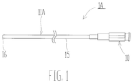
- a catheter device 1A comprises a catheter 11A, and the catheter 11A has an operating portion 10 to be operated by an operator, a main body 15 extending from the operating portion 10 and a distal end part 16 located at the distal end side of the main body 15.
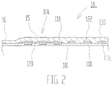
- the catheter 11A has a tubular inner layer 100 as shown in Fig. 2 .
- the inner layer 100 comprises an inner lumen 101 through which a guide wire or the like is to be inserted.
- a coil body 110 is disposed at the outer periphery of the inner layer 100 as a reinforcement body in which a wire 110a is spirally wound.
- a protective layer 120 is formed on the outer periphery of a distal end part corresponding to one end of the coil body 110 such that the distal end part of the coil body 110 is covered with the protective layer 120. Note that in the proximal end side relative to the distal end part of the coil body 110, an unprotected portion 122 is formed which is not covered with the protective layer 120. Therefore, the protective layer 120 partially covers the outer periphery of the coil body 110.
- a portion of the coil body 110 covered with the protective layer 120 is in a state where the wire 110a of the coil body 110 is buried in the inner layer 100 toward the side of the inner layer 100.
- the wire 110a of the coil body 110 at the unprotected portion 122 is not buried in the inner layer 100.
- an outer layer 130 is formed on the outer peripheries of the inner layer 100, the coil body 110 and the protective layer 120, and the inner layer 100, the coil body 110 and the protective layer 120 are covered with the outer layer 130.
- a coating layer covering the outer layer 130 may be provided on the outer periphery of the outer layer 130.
- distal end part 16 of the catheter 11A is constituted of a part of the inner layer 100, a part of the coil body 110, the protective layer 120, a part of the unprotected portion 122 and a part of the outer layer 130.
- the inner layer 100 preferably comprises a resin such as polyethylene, polyurethane, polyamide, polyamide elastomer, polyolefine, polyester or polyester elastomer. Further, in view of slideability of a guide wire and the like to be inserted into the inner lumen 101, the inner periphery of the inner layer 100 may be coated with a fluorine-based resin such as PEFE.
- a resin such as polyethylene, polyurethane, polyamide, polyamide elastomer, polyolefine, polyester or polyester elastomer.
- the coil body 110 preferably comprises stainless steel (SUS 304), tungsten or a superelastic alloy such as a Ni-Ti alloy.
- the cross sectional shape of the wire 110a of the coil body 110 is not limited to a rectangular shape, and it may be a circular shape, an elliptical shape, a polygonal shape or the like.
- the protective layer 120 desirably comprises a heat-shrinkable resin tube having a melting point higher than the outer layer 130.
- a tubes comprising polyethylene terephthalate resin (PET resin), polyimide resin, or polyether ether ketone resin (PEEK resin).
- PET resin polyethylene terephthalate resin
- PEEK resin polyether ether ketone resin
- the protective layer 120 may comprise a metal material, but preferably comprises a resin in view of easier manufacturing and processing of the catheter 11A. Further, breakage of the catheter 11A can be prevented in general if a low stiffness resin is used for the protective layer 120.
- the outer layer 130 desirably comprises a resin such as polyethylene, polyurethane, polyamide, polyamide elastomer, polyolefine, polyester or polyester elastomer.
- a lift of the coil body 110 from the inner layer 100 due to the springback can be prevented by virtue of the protective layer 120 when the catheter 11A is bent.
- the distal end part of the coil body 110 covered with the protective layer 120 is buried in the inner layer 100, and the periphery of the wire 110a of the coil body 110 at that portion is covered with the inner layer 100. Therefore, the distal end part of the coil body 110 is constrained by the inner layer 100, and more resistant to a lift of the distal end part of the coil body 110 when bent.
- the catheter 11A can be prevented from having a larger outer diameter because the distal end part of the coil body 110 is buried in the inner layer 100.
- the flexibility as an elastic body is not impaired because the wire 110a of the coil body 110 at the unprotected portion 122 is not buried in the inner layer 100.
- the catheter 11A can more easily bend along a blood vessel or the digestive organ. As a result, the catheter 11A is more resistant to breakage on the way when inserted into a blood vessel or the digestive organ.
- wire 110a of the coil body 110 may be completely buried in the inner layer 100, or may be partially buried in the inner layer 100.
- the coil body 110 is wound around the outer periphery of the inner layer 100, and a heat-shrinkable resin tube 120a is further placed on the outer periphery of the distal end part of the coil body 110.
- the heat-shrinkable resin tube 120a is heated and shrunk to form the protective layer 120, and at the same time, the wire 110a of the distal end part of the coil body 110 is pressed against the side of the inner layer 100 to be buried by a depth, d, as shown in Fig. 3B .
- the outer layer 130 is fused to the outer peripheries of the inner layer 100, the coil body 110 and the protective layer 120 as shown in Fig. 3C .
- the outer layer 130 may be formed after performing thermal shrinkage of the heat-shrinkable resin tube to form the protective layer 120, or may be formed upon performing the thermal shrinkage.
- the manufacturing process can be simplified in a case where the heat-shrinkable resin tube 120a is used for the protective layer 120 because the protective layer 120 can be formed simultaneously when the outer layer 130 is fused with the inner layer 100.
- the protective layer 120 may be formed on the periphery of the coil body 110 after the coil body 110 is buried to the side of the inner layer 100 by the so-called swaging process.
- a tube comprising a resin material or a metal material as the protective layer 120 may be placed on the outer periphery of the distal end part of the coil body 110 instead of the heat-shrinkable nature tube 120a. Then, the wire 110a of the coil body 110 may be buried in the side of the inner layer 100 by the swaging process.
- a catheter 11B according to Example 2 will be described with reference to Fig. 4 . Note that the same reference numbers are assigned to structures similar to those in Example 1, and the descriptions thereof are omitted.
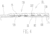
- the catheter 11B in a catheter device 1B comprises a braid 111 in which two or more wires 111a are woven in a mesh-like manner instead of the coil body 110 in Example 1.
- the braid 111 serves as a reinforcement body.
- the multiple wires 111a of the braid 111 preferably comprise stainless steel (SUS 304), tungsten or a superelastic alloy such as a Ni-Ti alloy.
- the cross sectional shapes of the two or more wires 111 a of the braid 111 are not limited to be rectangular, and they may be circular, elliptical, polygonal or the like.
- the distal end part of the braid 111 is covered with the protective layer 120, and further, the wires 111a of the braid 111 covered with the protective layer 120 are buried in the inner layer 100.
- a lift of the braid 111 from the inner layer 100 due to the springback can be prevented by virtue of the protective layer 120 when the catheter 11B is bent. Further, the distal end part of the braid 111 covered with the protective layer 120 is buried in the inner layer 100, and constrained by being covered with the inner layer 100. Therefore, a lift of the braid 111 can be even further prevented when bent. Moreover, the catheter 11B can be prevented from having a large outer diameter because the braid 111 is buried in the inner layer 100. Further, the flexibility as an elastic body is not impaired because the wires 111a of the braid 111 at the unprotected portion 122 are not buried in the inner layer 100.
- the catheter 11B can more easily bend along a blood vessel or the digestive organ as compared with a case where the full length of the braid 111 is buried in the inner layer 100 without forming the unprotected portion 122. As a result, the catheter 11B is more resistant to breakage on the way when the catheter 11B is inserted into a blood vessel or the digestive organ.
- a catheter 11 C according to Example 3 will be described with reference to Fig. 5 . Note that the same reference numbers are assigned to structures similar to those in Examples 1 and 2, and the descriptions thereof are omitted.
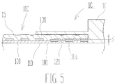
- a protective layer 121 is also formed at a proximal end part, which corresponds to the other end, in addition to the distal end part of the coil body 110. Further, the proximal end part of the coil body 110 is buried in the side of the inner layer 100 by a depth, d, using the protective layer 121.
- a lift of the coil body 110 can be prevented at the distal end part and the proximal end part of the coil body 110. Further, the distal end part and the proximal end part of the coil body 110 can be prevented from having large outer diameters.
- a balloon catheter 1D according to Example 4 will be described with reference to Fig. 6 . Note that the same reference numbers are assigned to structures similar to those in Examples 1 to 3, and the descriptions thereof are omitted.
- the balloon catheter 1D used for treating a stenosis site, for example, in a blood vessel of the heart comprises a balloon 20.
- the balloon catheter 1D further comprises an outer shaft 30, a connector 40, an inner shaft 50 corresponding to the catheter 11A, a tip 60 and a core wire 90.
- the balloon 20 has a function to expand a stenosis site, and comprises a resin material.
- the balloon 20 further has a distal end attachment part 22 at the distal end side, and a proximal end attachment part 23 at the proximal end side.
- the distal end attachment part 22 is joined to the distal end of the inner shaft 50 through the tip 60, and the proximal end attachment part 23 is joined to the distal end of the outer shaft 30.
- the outer shaft 30 has a function to supply a fluid, and comprises a tubular member constituting an inflation lumen 36 for supplying the fluid. Further, the outer shaft 30 has a distal end outer shaft portion 31, a guide wire port portion 33, a middle outer shaft portion 35 and a proximal end outer shaft portion 37 in the order from the distal end side. Note that the guide wire port portion 33 corresponds to a portion where the distal end outer shaft portion 31, the middle outer shaft portion 35 and the inner shaft 50 are joined.
- the balloon catheter 1D in the aforementioned configuration has an inner shaft 50 which is the catheter 11A in which a lift of an end of the coil body 110 can be prevented. Therefore, a lift of an end of the coil body 110 can effectively be prevented, although the end of the coil body 110 might otherwise be caused by the pressure applied in the direction of the outer periphery due to a contrast agent, a saline solution or the like when a balloon 20 is inflated.
- a balloon catheter 1E according to Example 5 will be described with reference to Fig. 8 . Note that the same reference numbers are assigned to structures similar to those in Examples 1 to 4, and the descriptions thereof are omitted.
- the balloon catheter IE comprises the catheter 11A according to Example 1 as the distal end outer shaft portion 31. Again, according to the aforementioned construction, a lift of an end portion of the coil body 110 can be prevented in the balloon catheter 1E.
- the catheter 11 A according to Example 1 is used as the inner shaft 50 and the distal end outer shaft portion 31 in Examples 4 and 5, but the configurations shall not be limited to these.
- the catheter 11B according to Example 2 may be used as the inner shaft 50 and the distal end outer shaft portion 31, or the catheter 11 C according to Example 3 may be used as the inner shaft 50 and the distal end outer shaft portion 31.
- the coil body 110 and the braid 111 as the reinforcement bodies are not buried in the inner layer 100 at all at the unprotected portion 122 which is not covered with the protective layer 120, but the configuration shall not be limited to this.
- the coil body 110 and the braid 111 as the reinforcement bodies may be somewhat buried in the inner layer 100 to an extent that flexibility as an elastic body is not lost.
Landscapes
- Health & Medical Sciences (AREA)
- Life Sciences & Earth Sciences (AREA)
- Heart & Thoracic Surgery (AREA)
- Hematology (AREA)
- Engineering & Computer Science (AREA)
- Anesthesiology (AREA)
- Biomedical Technology (AREA)
- Pulmonology (AREA)
- Biophysics (AREA)
- Animal Behavior & Ethology (AREA)
- General Health & Medical Sciences (AREA)
- Public Health (AREA)
- Veterinary Medicine (AREA)
- Child & Adolescent Psychology (AREA)
- Media Introduction/Drainage Providing Device (AREA)
- Materials For Medical Uses (AREA)
Abstract
Description
- The present invention relates to a catheter and a balloon catheter for medical use.
- As a conventional catheter, for example, a configuration as disclosed in
Patent Document 1 has already been proposed comprising: an elongated tubular main body including an inner layer, a coil layer (a reinforcement body) formed with a wire material wound around the outer periphery of the inner layer and an outer layer covering the coil body. - Further, Patent Document 2 discloses a medical tube comprising an inner layer, a reinforcement layer configured with a coil layer including a first coil and a second coil adhering to the outside of the inner layer and an outer layer adhering to the outside of the reinforcement layer.
- However, the catheter according to
Patent Document 1 and the medical tube according to Patent Document 2 described above have the following problem: a coil as a reinforcement body tends to expand due to the springback when bent, resulting in a lift of an end of the coil. - Moreover, as a configuration which may solve the above problem, Patent Document 3 discloses an outer catheter comprising: an inner layer, an outer layer and an intermediate layer (a reinforcement body) formed with a linear object and provided so as to be sandwiched between the inner layer and the outer layer, wherein the distal end of the intermediate layer is covered with an contrasting ring (a protective layer).
-
- Patent Document 1 :
Japanese Patent Application Laid-Open No. 2012-100829 - Patent Document 2:
Japanese Patent No. 3659664 - Patent Document 3 :
Japanese Patent Application Laid-Open No. 2012-249812 - However, in the case of the outer catheter according to Patent Document 3, the outer diameter of the catheter is disadvantageously larger at an end of the intermediate layer because the contrasting ring is thick.
- Accordingly, an objective of the present invention is to provide a catheter and a balloon catheter in which a lift of a reinforcement body can be prevented without increasing the outer diameter at an end of the reinforcement body.
- The present invention provides a catheter comprising: a tubular inner layer, a reinforcement body wound around the outer periphery of the inner layer, a protective layer partially covering the outer periphery of the reinforcement body, and an outer layer covering at least the outer periphery of the protective layer, wherein the protective layer covers at least the outer periphery of one end of the reinforcement body, and the one end of the reinforcement body covered with the protective layer is buried deeper in a side of the inner layer relative to a portion of the reinforcement body not covered with the protective layer.
- In the aforementioned configuration, a lift of an end of the reinforcement body when bent can be prevented because the end of the reinforcement body is covered with the protective layer. Further, the end of the reinforcement body covered with the protective layer is buried and constrained in the inner layer. Therefore, a relative movement to the inner layer is controlled as compared with an unburied portion of the reinforcement body, and a lift when bent can be prevented more reliably. Furthermore, the end of the reinforcement body is buried in the inner layer, and thus the outer diameter of the whole catheter at that portion can be prevented from becoming larger than those of other portions.
- In addition, the protective layer is desirably configured with a resin.
- A catheter having the aforementioned configuration can easily be manufactured and processed. In addition, breakage of a catheter can be prevented in general if a low stiffness resin is used for the protective layer.
- Further, the protective layer is desirably configured with a heat-shrinkable resin tube.
- The manufacturing process can be simplified when the protective layer is configured with a so-called heat-shrinkable resin tube according to the aforementioned configuration.
- In addition, preferably, the outer layer is configured with a resin, and the resin of the protective layer has a higher melting point than that of the outer layer.
- According to the aforementioned configuration, the protective layer can be prevented from becoming thinner when the outer layer is fused to the inner layer. Therefore, the strength of the protective layer can be assured, and a risk of a lifted end of the reinforcement body can be prevented even more reliably.
- In addition, the protective layer desirably covers both the one end and the other end of the reinforcement body.
- According to the aforementioned configuration, a lift of the reinforcement body from the inner layer due to the springback can be prevented even more reliably, and the outer diameters at one end and the other end of the reinforcement body can also be prevented from becoming larger.
- Further, a balloon catheter according to the present invention comprises the above catheter and a balloon joined to the outer periphery of the outer layer in the above catheter.
- According to the aforementioned configuration, a balloon catheter can be provided having a structure in which a lift of an end of the reinforcement body can be prevented.
- The present invention can provide a catheter in which a lift of an end of a reinforcement body can be prevented without increasing the outer diameter at the end of the reinforcement body.
- Further, the present invention can provide a balloon catheter having a structure in which a lift of an end of a reinforcement body can be prevented without increasing the outer diameter at the end of the reinforcement body.
-
-
Fig. 1 shows a top view of the catheter according to Example 1. -
Fig. 2 shows an enlarged partial cross sectional view of the catheter according to Example 1. -
Figs. 3A to 3C show a schematic diagram illustrating a manufacturing process of the catheter according to Example 1. -
Fig. 4 shows an enlarged partial cross sectional view of the catheter according to Example 2. -
Fig. 5 shows an enlarged partial cross sectional view of the catheter according to Example 3. -
Fig. 6 shows a partial cross sectional top view of the balloon catheter according to Example 4. -
Fig. 7 shows an enlarged partial cross sectional view of the balloon catheter according to Example 4. -
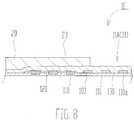
Fig. 8 shows an enlarged partial cross sectional view of the balloon catheter according to Example 5. - Below, Examples in which the catheters according to the present invention are embodied will be described in detail. However, the present invention shall not be limited to Examples shown below, and modifications in design can be made appropriately. In
Figs. 1 to 8 , the left side corresponds to the distal end side which is to be inserted into the body, and the right side corresponds to the proximal side which is to be operated by an operator such as a physician. - As shown in
Fig. 1 , acatheter device 1A comprises acatheter 11A, and thecatheter 11A has anoperating portion 10 to be operated by an operator, amain body 15 extending from theoperating portion 10 and adistal end part 16 located at the distal end side of themain body 15. - More specifically, the
catheter 11A has a tubularinner layer 100 as shown inFig. 2 . Theinner layer 100 comprises aninner lumen 101 through which a guide wire or the like is to be inserted. - Further, a
coil body 110 is disposed at the outer periphery of theinner layer 100 as a reinforcement body in which awire 110a is spirally wound. - Moreover, a
protective layer 120 is formed on the outer periphery of a distal end part corresponding to one end of thecoil body 110 such that the distal end part of thecoil body 110 is covered with theprotective layer 120. Note that in the proximal end side relative to the distal end part of thecoil body 110, anunprotected portion 122 is formed which is not covered with theprotective layer 120. Therefore, theprotective layer 120 partially covers the outer periphery of thecoil body 110. - Further, a portion of the
coil body 110 covered with theprotective layer 120 is in a state where thewire 110a of thecoil body 110 is buried in theinner layer 100 toward the side of theinner layer 100. In contrast, thewire 110a of thecoil body 110 at theunprotected portion 122 is not buried in theinner layer 100. - In addition, an
outer layer 130 is formed on the outer peripheries of theinner layer 100, thecoil body 110 and theprotective layer 120, and theinner layer 100, thecoil body 110 and theprotective layer 120 are covered with theouter layer 130. - Further, a coating layer covering the
outer layer 130 may be provided on the outer periphery of theouter layer 130. - Note that the
distal end part 16 of thecatheter 11A is constituted of a part of theinner layer 100, a part of thecoil body 110, theprotective layer 120, a part of theunprotected portion 122 and a part of theouter layer 130. - Note that the
inner layer 100 preferably comprises a resin such as polyethylene, polyurethane, polyamide, polyamide elastomer, polyolefine, polyester or polyester elastomer. Further, in view of slideability of a guide wire and the like to be inserted into theinner lumen 101, the inner periphery of theinner layer 100 may be coated with a fluorine-based resin such as PEFE. - Moreover, the
coil body 110 preferably comprises stainless steel (SUS 304), tungsten or a superelastic alloy such as a Ni-Ti alloy. Note that the cross sectional shape of thewire 110a of thecoil body 110 is not limited to a rectangular shape, and it may be a circular shape, an elliptical shape, a polygonal shape or the like. - Further, the
protective layer 120 desirably comprises a heat-shrinkable resin tube having a melting point higher than theouter layer 130. Preferred are, for example, a tubes comprising polyethylene terephthalate resin (PET resin), polyimide resin, or polyether ether ketone resin (PEEK resin). This can prevent theprotective layer 120 from becoming thinner when fused, in a case where theouter layer 130 is fused to theinner layer 100. As a result, the strength of theprotective layer 120 can be assured, and a risk of a lifted end of thecoil body 110 can be prevented. Note that theprotective layer 120 may comprise a metal material, but preferably comprises a resin in view of easier manufacturing and processing of thecatheter 11A. Further, breakage of thecatheter 11A can be prevented in general if a low stiffness resin is used for theprotective layer 120. - Moreover, the
outer layer 130 desirably comprises a resin such as polyethylene, polyurethane, polyamide, polyamide elastomer, polyolefine, polyester or polyester elastomer. - According to the
catheter 11A, a lift of thecoil body 110 from theinner layer 100 due to the springback can be prevented by virtue of theprotective layer 120 when thecatheter 11A is bent. Further, the distal end part of thecoil body 110 covered with theprotective layer 120 is buried in theinner layer 100, and the periphery of thewire 110a of thecoil body 110 at that portion is covered with theinner layer 100. Therefore, the distal end part of thecoil body 110 is constrained by theinner layer 100, and more resistant to a lift of the distal end part of thecoil body 110 when bent. Furthermore, thecatheter 11A can be prevented from having a larger outer diameter because the distal end part of thecoil body 110 is buried in theinner layer 100. - In addition, the flexibility as an elastic body is not impaired because the
wire 110a of thecoil body 110 at theunprotected portion 122 is not buried in theinner layer 100. Compared with a case where the full length of thecoil body 110 is buried in theinner layer 100 without providing theunprotected portion 122, thecatheter 11A can more easily bend along a blood vessel or the digestive organ. As a result, thecatheter 11A is more resistant to breakage on the way when inserted into a blood vessel or the digestive organ. - Note that the
wire 110a of thecoil body 110 may be completely buried in theinner layer 100, or may be partially buried in theinner layer 100. - Below, a method for manufacturing the
catheter 11A will be described briefly. First, as shown inFig. 3A , thecoil body 110 is wound around the outer periphery of theinner layer 100, and a heat-shrinkable resin tube 120a is further placed on the outer periphery of the distal end part of thecoil body 110. - Next, the heat-
shrinkable resin tube 120a is heated and shrunk to form theprotective layer 120, and at the same time, thewire 110a of the distal end part of thecoil body 110 is pressed against the side of theinner layer 100 to be buried by a depth, d, as shown inFig. 3B . - Then, the
outer layer 130 is fused to the outer peripheries of theinner layer 100, thecoil body 110 and theprotective layer 120 as shown inFig. 3C . Note that theouter layer 130 may be formed after performing thermal shrinkage of the heat-shrinkable resin tube to form theprotective layer 120, or may be formed upon performing the thermal shrinkage. - The manufacturing process can be simplified in a case where the heat-
shrinkable resin tube 120a is used for theprotective layer 120 because theprotective layer 120 can be formed simultaneously when theouter layer 130 is fused with theinner layer 100. - Note that the above manufacturing method is merely an example, and a different manufacturing method may be used, of course. For example, the
protective layer 120 may be formed on the periphery of thecoil body 110 after thecoil body 110 is buried to the side of theinner layer 100 by the so-called swaging process. Alternatively, a tube comprising a resin material or a metal material as theprotective layer 120 may be placed on the outer periphery of the distal end part of thecoil body 110 instead of the heat-shrinkable nature tube 120a. Then, thewire 110a of thecoil body 110 may be buried in the side of theinner layer 100 by the swaging process. - A catheter 11B according to Example 2 will be described with reference to
Fig. 4 . Note that the same reference numbers are assigned to structures similar to those in Example 1, and the descriptions thereof are omitted. - The catheter 11B in a
catheter device 1B comprises abraid 111 in which two or more wires 111a are woven in a mesh-like manner instead of thecoil body 110 in Example 1. Thebraid 111 serves as a reinforcement body. Note that the multiple wires 111a of thebraid 111 preferably comprise stainless steel (SUS 304), tungsten or a superelastic alloy such as a Ni-Ti alloy. The cross sectional shapes of the two or more wires 111 a of thebraid 111 are not limited to be rectangular, and they may be circular, elliptical, polygonal or the like. - In addition, the distal end part of the
braid 111 is covered with theprotective layer 120, and further, the wires 111a of thebraid 111 covered with theprotective layer 120 are buried in theinner layer 100. - Again, according to the aforementioned configuration, a lift of the
braid 111 from theinner layer 100 due to the springback can be prevented by virtue of theprotective layer 120 when the catheter 11B is bent. Further, the distal end part of thebraid 111 covered with theprotective layer 120 is buried in theinner layer 100, and constrained by being covered with theinner layer 100. Therefore, a lift of thebraid 111 can be even further prevented when bent. Moreover, the catheter 11B can be prevented from having a large outer diameter because thebraid 111 is buried in theinner layer 100. Further, the flexibility as an elastic body is not impaired because the wires 111a of thebraid 111 at theunprotected portion 122 are not buried in theinner layer 100. The catheter 11B can more easily bend along a blood vessel or the digestive organ as compared with a case where the full length of thebraid 111 is buried in theinner layer 100 without forming theunprotected portion 122. As a result, the catheter 11B is more resistant to breakage on the way when the catheter 11B is inserted into a blood vessel or the digestive organ. - A
catheter 11 C according to Example 3 will be described with reference toFig. 5 . Note that the same reference numbers are assigned to structures similar to those in Examples 1 and 2, and the descriptions thereof are omitted. - In the
catheter 11 C used for acatheter device 1C, aprotective layer 121 is also formed at a proximal end part, which corresponds to the other end, in addition to the distal end part of thecoil body 110. Further, the proximal end part of thecoil body 110 is buried in the side of theinner layer 100 by a depth, d, using theprotective layer 121. - According to the aforementioned configuration, a lift of the
coil body 110 can be prevented at the distal end part and the proximal end part of thecoil body 110. Further, the distal end part and the proximal end part of thecoil body 110 can be prevented from having large outer diameters. - A
balloon catheter 1D according to Example 4 will be described with reference toFig. 6 . Note that the same reference numbers are assigned to structures similar to those in Examples 1 to 3, and the descriptions thereof are omitted. - The
balloon catheter 1D used for treating a stenosis site, for example, in a blood vessel of the heart comprises aballoon 20. Theballoon catheter 1D further comprises anouter shaft 30, aconnector 40, aninner shaft 50 corresponding to thecatheter 11A, atip 60 and acore wire 90. - The
balloon 20 has a function to expand a stenosis site, and comprises a resin material. Theballoon 20 further has a distalend attachment part 22 at the distal end side, and a proximalend attachment part 23 at the proximal end side. The distalend attachment part 22 is joined to the distal end of theinner shaft 50 through thetip 60, and the proximalend attachment part 23 is joined to the distal end of theouter shaft 30. - The
outer shaft 30 has a function to supply a fluid, and comprises a tubular member constituting aninflation lumen 36 for supplying the fluid. Further, theouter shaft 30 has a distal endouter shaft portion 31, a guidewire port portion 33, a middleouter shaft portion 35 and a proximal endouter shaft portion 37 in the order from the distal end side. Note that the guidewire port portion 33 corresponds to a portion where the distal endouter shaft portion 31, the middleouter shaft portion 35 and theinner shaft 50 are joined. - As shown in
Fig. 7 , theballoon catheter 1D in the aforementioned configuration has aninner shaft 50 which is thecatheter 11A in which a lift of an end of thecoil body 110 can be prevented. Therefore, a lift of an end of thecoil body 110 can effectively be prevented, although the end of thecoil body 110 might otherwise be caused by the pressure applied in the direction of the outer periphery due to a contrast agent, a saline solution or the like when aballoon 20 is inflated. - A
balloon catheter 1E according to Example 5 will be described with reference toFig. 8 . Note that the same reference numbers are assigned to structures similar to those in Examples 1 to 4, and the descriptions thereof are omitted. - As shown in
Fig. 8 , the balloon catheter IE comprises thecatheter 11A according to Example 1 as the distal endouter shaft portion 31. Again, according to the aforementioned construction, a lift of an end portion of thecoil body 110 can be prevented in theballoon catheter 1E. - Note that the present invention shall not be limited to the embodiments according to Examples 1 to 5, and a wide range of modifications in dimensions and shapes of components can be made appropriately.
- Further, the
catheter 11 A according to Example 1 is used as theinner shaft 50 and the distal endouter shaft portion 31 in Examples 4 and 5, but the configurations shall not be limited to these. For example, the catheter 11B according to Example 2 may be used as theinner shaft 50 and the distal endouter shaft portion 31, or thecatheter 11 C according to Example 3 may be used as theinner shaft 50 and the distal endouter shaft portion 31. - Furthermore, in Examples 1 to 5 described above, the
coil body 110 and thebraid 111 as the reinforcement bodies are not buried in theinner layer 100 at all at theunprotected portion 122 which is not covered with theprotective layer 120, but the configuration shall not be limited to this. At theunprotected portion 122, thecoil body 110 and thebraid 111 as the reinforcement bodies may be somewhat buried in theinner layer 100 to an extent that flexibility as an elastic body is not lost. -
- 1A, 1B, 1C
- Catheter device
- 1D, IE
- Balloon catheter
- 11A, 11B, 11C
- Catheter
- 20
- Balloon
- 100
- Inner layer
- 110
- Coil body (reinforcement body)
- 111
- Braid (reinforcement body)
- 120
- Protective layer
- 122
- Unprotected portion
- 130
- Outer layer
Claims (8)
- A catheter (11A, 11B, 11C) comprising:a tubular inner layer (100);a reinforcement body (110, 111) wound around an outer periphery of the inner layer (100);a protective layer (120, 121) partially covering an outer periphery of the reinforcement body (110, 111); andan outer layer (130) covering at least an outer periphery of the protective layer (120, 121), characterized in thatthe protective layer (120, 121) covers at least an outer periphery of one end of the reinforcement body (110, 111), and the one end of the reinforcement body (110, 111) covered with the protective layer (120, 121) is buried deeper in a side of the inner layer (100) relative to a portion (122) of the reinforcement body (110, 111) not covered with the protective layer (120, 121).
- The catheter (11A, 11B, 11C) according to claim 1, wherein the protective layer (120, 121) comprises a resin.
- The catheter (11A, 11B, 11C) according to claim 1 or 2, wherein the protective layer (120, 121) comprises a heat-shrinkable resin tube.
- The catheter (11A, 11B, 11C) according to claim 2 or 3, wherein the outer layer (130) comprises a resin, and the resin of the protective layer (120, 121) has a melting point higher than that of the outer layer (130).
- The catheter (11A, 11 B, 11C) according to any one of claims 1 to 4, wherein the protective layer (120, 121) covers both the one end and the other end of the reinforcement body (110, 111).
- The catheter (11A, 11C) according to any one of claims 1 to 5, wherein the reinforcement body (110) is configured by a coil body (110).
- The catheter (11B) according to any one of claims 1 to 5, wherein the reinforcement body (111) is configured by a braid (111).
- A balloon catheter (1D, 1E) comprising:the catheter (11A, 11B, 11C) according to any one of claims 1 to 7, anda balloon (20) joined to an outer periphery of the outer layer (130) in the catheter (11A, 11B, 11C).
Applications Claiming Priority (1)
| Application Number | Priority Date | Filing Date | Title |
|---|---|---|---|
| JP2015157962A JP6426068B2 (en) | 2015-08-10 | 2015-08-10 | Catheter and balloon catheter |
Publications (2)
| Publication Number | Publication Date |
|---|---|
| EP3130372A1 true EP3130372A1 (en) | 2017-02-15 |
| EP3130372B1 EP3130372B1 (en) | 2020-01-08 |
Family
ID=56296628
Family Applications (1)
| Application Number | Title | Priority Date | Filing Date |
|---|---|---|---|
| EP16177043.3A Active EP3130372B1 (en) | 2015-08-10 | 2016-06-30 | Catheter and balloon catheter |
Country Status (5)
| Country | Link |
|---|---|
| US (2) | US10653858B2 (en) |
| EP (1) | EP3130372B1 (en) |
| JP (1) | JP6426068B2 (en) |
| KR (2) | KR102119293B1 (en) |
| CN (2) | CN111701136A (en) |
Cited By (1)
| Publication number | Priority date | Publication date | Assignee | Title |
|---|---|---|---|---|
| EP3546007A4 (en) * | 2016-11-24 | 2020-08-26 | Asahi Intecc Co., Ltd. | CATHETER AND BALLOON CATHETER |
Families Citing this family (8)
| Publication number | Priority date | Publication date | Assignee | Title |
|---|---|---|---|---|
| EP3442642B1 (en) | 2016-04-12 | 2025-10-15 | Boston Scientific Scimed, Inc. | Method of making a catether assembly |
| EP4032578A1 (en) | 2016-07-13 | 2022-07-27 | Perfuze Limited | High flexibility, kink resistant catheter shaft |
| WO2018111898A1 (en) | 2016-12-13 | 2018-06-21 | Boston Scientific Scimed, Inc. | Medical balloon |
| WO2018200661A1 (en) | 2017-04-25 | 2018-11-01 | Boston Scientific Scimed, Inc. | Medical balloon |
| CN111465420B (en) | 2017-12-15 | 2023-04-18 | 佩尔福兹有限公司 | Improved catheter and apparatus and system incorporating same |
| KR102517517B1 (en) * | 2021-01-27 | 2023-04-05 | 주식회사 엔스퀘어 | Needleless drug injection apparatus of induced current type |
| JP7656470B2 (en) * | 2021-04-13 | 2025-04-03 | 朝日インテック株式会社 | Medical Tubing and Catheters |
| KR102794944B1 (en) * | 2022-04-14 | 2025-04-15 | 윤영수 | Endoscope tube |
Citations (7)
| Publication number | Priority date | Publication date | Assignee | Title |
|---|---|---|---|---|
| JPH07323090A (en) * | 1994-05-31 | 1995-12-12 | Terumo Corp | Medical tube |
| EP1721631A1 (en) * | 2005-05-13 | 2006-11-15 | Terumo Kabushiki Kaisha | Catheter |
| JP2012100829A (en) | 2010-11-09 | 2012-05-31 | Sumitomo Bakelite Co Ltd | Catheter and method of manufacturing the same |
| JP2012249811A (en) * | 2011-06-02 | 2012-12-20 | Goodman Co Ltd | Medical instruments |
| JP2012249812A (en) | 2011-06-02 | 2012-12-20 | Goodman Co Ltd | Medical instrument |
| EP2762187A1 (en) * | 2013-01-30 | 2014-08-06 | Asahi Intecc Co., Ltd. | Catheter |
| WO2014189828A1 (en) * | 2013-05-19 | 2014-11-27 | Cordis Corporation | Large lumen guide catheter |
Family Cites Families (83)
| Publication number | Priority date | Publication date | Assignee | Title |
|---|---|---|---|---|
| GB1439027A (en) * | 1973-07-18 | 1976-06-09 | Fibreglass Ltd | Manufacture of glass wool |
| US3980453A (en) * | 1973-10-09 | 1976-09-14 | Heijiro Fukuda | Laminated resinoid wheels, method for continuously producing same and apparatus for use in the method |
| US3926705A (en) * | 1974-07-25 | 1975-12-16 | Western Acadia | Silicone catheter and process for manufacturing same |
| US5646076A (en) * | 1979-12-21 | 1997-07-08 | Bortz; David N. | Friction controlling devices and methods of their manufacture |
| US4705511A (en) * | 1985-05-13 | 1987-11-10 | Bipore, Inc. | Introducer sheath assembly |
| US4698242A (en) * | 1985-08-12 | 1987-10-06 | National Starch And Chemical Corporation | Thermoplastic elastic adhesive containing polyether block amides |
| US5679399A (en) * | 1987-07-17 | 1997-10-21 | Bio Barrier, Inc. | Method of forming a membrane, especially a latex or polymer membrane, including multiple discrete layers |
| JPS6480367A (en) * | 1987-09-21 | 1989-03-27 | Terumo Corp | Member for correcting ureter |
| US4985019A (en) * | 1988-03-11 | 1991-01-15 | Michelson Gary K | X-ray marker |
| US5432000A (en) * | 1989-03-20 | 1995-07-11 | Weyerhaeuser Company | Binder coated discontinuous fibers with adhered particulate materials |
| US5272012A (en) * | 1989-06-23 | 1993-12-21 | C. R. Bard, Inc. | Medical apparatus having protective, lubricious coating |
| US5084022A (en) * | 1989-10-04 | 1992-01-28 | Lake Region Manufacturing Company, Inc. | Graduated guidewire |
| US5304205A (en) * | 1989-12-11 | 1994-04-19 | Mitsui Toatsu Chemicals, Incorporated | Surgical filament |
| DK146790D0 (en) * | 1990-06-15 | 1990-06-15 | Meadox Surgimed As | PROCEDURE FOR THE PREPARATION OF A FERTILIZER COATING COATING AND MEDICAL INSTRUMENT WITH COATING COATING |
| US5279596A (en) * | 1990-07-27 | 1994-01-18 | Cordis Corporation | Intravascular catheter with kink resistant tip |
| US5163921A (en) * | 1990-10-04 | 1992-11-17 | Feiring Andrew J | Valved perfusion cardiovascular catheters |
| US5228453A (en) * | 1991-05-07 | 1993-07-20 | Target Therapeutics, Inc. | Catheter guide wire |
| US5443907A (en) * | 1991-06-18 | 1995-08-22 | Scimed Life Systems, Inc. | Coating for medical insertion guides |
| US5213111A (en) * | 1991-07-10 | 1993-05-25 | Cook Incorporated | Composite wire guide construction |
| US5358493A (en) * | 1993-02-18 | 1994-10-25 | Scimed Life Systems, Inc. | Vascular access catheter and methods for manufacture thereof |
| DE4310378A1 (en) * | 1993-03-30 | 1994-10-06 | Aigner Karl | Balloon catheter and device for isolated perfusion by means of the balloon catheter |
| NL9300670A (en) * | 1993-04-20 | 1994-11-16 | Cordis Europ | Catheter with electrically conductive wire reinforcement. |
| US5344419A (en) * | 1993-04-23 | 1994-09-06 | Wayne State University | Apparatus and method for making a diffusing tip in a balloon catheter system |
| US5379779A (en) * | 1993-08-16 | 1995-01-10 | Boston Scientific Corporation | Zebra exchange guidewire |
| US5404887A (en) * | 1993-11-04 | 1995-04-11 | Scimed Life Systems, Inc. | Guide wire having an unsmooth exterior surface |
| EP0732954B1 (en) * | 1993-12-10 | 1998-08-19 | Schneider (Usa) Inc. | Guiding catheter |
| US5545151A (en) * | 1994-11-22 | 1996-08-13 | Schneider (Usa) Inc | Catheter having hydrophobic properties |
| DE69504104T2 (en) * | 1995-01-04 | 1999-05-06 | Medtronic, Inc., Minneapolis, Minn. | IMPROVED METHOD FOR PRODUCING A SOFT TIP |
| US5762995A (en) * | 1995-01-13 | 1998-06-09 | Fuji Photo Optical Co., Ltd. | Flexible sheathing tube construction, and method for fabrication thereof |
| US6325790B1 (en) * | 1995-04-11 | 2001-12-04 | Cordis Corporation | Soft tip catheter |
| US5820607A (en) * | 1995-06-05 | 1998-10-13 | Board Of Regents, University Of Texas Systems | Multipurpose anti-microbial silastic sheath system for the prevention of device-related infections |
| CA2178541C (en) * | 1995-06-07 | 2009-11-24 | Neal E. Fearnot | Implantable medical device |
| NL1001746C2 (en) * | 1995-11-27 | 1997-05-30 | Belden Wire & Cable Bv | Guide wire for medical application. |
| EP0877636B1 (en) * | 1996-01-31 | 2002-10-02 | E.I. Du Pont De Nemours And Company | Dilatation catheter balloons with improved puncture resistance |
| US5827201A (en) * | 1996-07-26 | 1998-10-27 | Target Therapeutics, Inc. | Micro-braided guidewire |
| US5971975A (en) * | 1996-10-09 | 1999-10-26 | Target Therapeutics, Inc. | Guide catheter with enhanced guidewire tracking |
| US5755704A (en) * | 1996-10-29 | 1998-05-26 | Medtronic, Inc. | Thinwall guide catheter |
| US5938653A (en) * | 1997-06-09 | 1999-08-17 | Scimed Life Systems, Inc. | Catheter having controlled flexibility and method of manufacture |
| US6217566B1 (en) * | 1997-10-02 | 2001-04-17 | Target Therapeutics, Inc. | Peripheral vascular delivery catheter |
| US6083167A (en) * | 1998-02-10 | 2000-07-04 | Emory University | Systems and methods for providing radiation therapy and catheter guides |
| US6593255B1 (en) * | 1998-03-03 | 2003-07-15 | Ppg Industries Ohio, Inc. | Impregnated glass fiber strands and products including the same |
| US6203505B1 (en) * | 1998-06-05 | 2001-03-20 | Advanced Cardiovascular Systems, Inc. | Guidewires having a vapor deposited primer coat |
| US6368316B1 (en) * | 1998-06-11 | 2002-04-09 | Target Therapeutics, Inc. | Catheter with composite stiffener |
| US6591472B1 (en) * | 1998-12-08 | 2003-07-15 | Medtronic, Inc. | Multiple segment catheter and method of fabrication |
| US6361557B1 (en) * | 1999-02-05 | 2002-03-26 | Medtronic Ave, Inc. | Staplebutton radiopaque marker |
| US6689120B1 (en) * | 1999-08-06 | 2004-02-10 | Boston Scientific Scimed, Inc. | Reduced profile delivery system |
| US6485735B1 (en) * | 1999-08-31 | 2002-11-26 | Phelps Dodge High Performance Conductors Of Sc & Ga, Inc. | Multilayer thermoset polymer matrix and structures made therefrom |
| JP3496636B2 (en) * | 2000-02-16 | 2004-02-16 | 日立電線株式会社 | Paint for partial discharge resistant enameled wire and partial discharge resistant enameled wire |
| US6817995B1 (en) * | 2000-04-20 | 2004-11-16 | Isotron ,Inc. | Reinforced catheter connector and system |
| JP2002136600A (en) * | 2000-10-30 | 2002-05-14 | Terumo Corp | Medical long body and method for manufacturing the same |
| US20020156460A1 (en) * | 2001-04-20 | 2002-10-24 | Scimed Life Systems, Inc | Microcatheter with improved distal tip and transitions |
| WO2003000116A2 (en) * | 2001-06-20 | 2003-01-03 | Microvention, Inc. | Medical devices having full or partial polymer coatings and their methods of manufacture |
| US6702782B2 (en) * | 2001-06-26 | 2004-03-09 | Concentric Medical, Inc. | Large lumen balloon catheter |
| US6638245B2 (en) * | 2001-06-26 | 2003-10-28 | Concentric Medical, Inc. | Balloon catheter |
| US6652507B2 (en) * | 2001-07-03 | 2003-11-25 | Scimed Life Systems, Inc. | Intravascular catheter having multi-layered tip |
| US7488338B2 (en) * | 2001-12-27 | 2009-02-10 | Boston Scientific Scimed, Inc. | Catheter having an improved torque transmitting shaft |
| US6945970B2 (en) * | 2001-12-27 | 2005-09-20 | Scimed Life Systems, Inc. | Catheter incorporating a curable polymer layer to control flexibility and method of manufacture |
| US7335184B2 (en) * | 2002-07-02 | 2008-02-26 | Sentient Engineering And Technology | Balloon catheter and treatment apparatus |
| US7081096B2 (en) * | 2003-01-24 | 2006-07-25 | Medtronic Vascular, Inc. | Temperature mapping balloon |
| US7687144B2 (en) * | 2003-02-20 | 2010-03-30 | Wilson-Cook Medical, Inc. | Medical device with adherent coating, and method for preparing same |
| US7175607B2 (en) * | 2003-03-06 | 2007-02-13 | Advanced Cardiovascular Systems, Inc. | Catheter balloon liner with variable thickness and method for making same |
| US7001369B2 (en) * | 2003-03-27 | 2006-02-21 | Scimed Life Systems, Inc. | Medical device |
| US7651469B2 (en) * | 2003-04-25 | 2010-01-26 | Cook Incorporated | Low friction coated marked wire guide for over the wire insertion of a catheter |
| US8535293B2 (en) * | 2004-04-13 | 2013-09-17 | Gyrus Acmi, Inc. | Atraumatic ureteral access sheath |
| US7354419B2 (en) * | 2004-10-15 | 2008-04-08 | Futuremed Interventional, Inc. | Medical balloon having strengthening rods |
| JP2006218070A (en) * | 2005-02-10 | 2006-08-24 | Piolax Medical Device:Kk | Catheter |
| US9163141B2 (en) * | 2006-04-27 | 2015-10-20 | Cryovac, Inc. | Polymeric blend comprising polylactic acid |
| AT503986B1 (en) * | 2006-08-02 | 2008-05-15 | Miba Gleitlager Gmbh | LAYER LAYER FOR A BEARING ELEMENT |
| US20080108974A1 (en) * | 2006-10-20 | 2008-05-08 | Vital Signs, Inc. | Reinforced catheter with radiopaque distal tip and process of manufacture |
| DE602006018949D1 (en) * | 2006-10-20 | 2011-01-27 | Pfrimmer Nutricia Gmbh | catheter system |
| US9028427B2 (en) * | 2007-03-14 | 2015-05-12 | Terumo Kabushiki Kaisha | Guide wire |
| EP2103323B1 (en) * | 2007-03-14 | 2012-04-25 | Terumo Kabushiki Kaisha | Guide wire |
| US7926728B2 (en) * | 2007-10-31 | 2011-04-19 | Infineon Technologies Ag | Integrated circuit device including a contactless integrated circuit inlay |
| US8106474B2 (en) * | 2008-04-18 | 2012-01-31 | Semiconductor Energy Laboratory Co., Ltd. | Semiconductor device |
| JP5147569B2 (en) * | 2008-06-30 | 2013-02-20 | テルモ株式会社 | Guide wire |
| JP5473443B2 (en) | 2009-07-15 | 2014-04-16 | 株式会社カネカ | catheter |
| US8617232B2 (en) * | 2009-09-25 | 2013-12-31 | Kyoto Medical Planning Co., Ltd. | Medical catheter apparatus |
| CN201596223U (en) * | 2009-12-28 | 2010-10-06 | 业聚医疗器械(深圳)有限公司 | Mini-catheter |
| US8034045B1 (en) * | 2010-05-05 | 2011-10-11 | Cook Medical Technologies Llc | Flexible sheath |
| DK177285B1 (en) * | 2011-03-05 | 2012-10-08 | Gianni Leoni | Dilation device |
| EP2719418B1 (en) * | 2011-06-08 | 2024-10-23 | Kaneka Corporation | Balloon catheter and method for producing same |
| US10130789B2 (en) * | 2011-06-30 | 2018-11-20 | Covidien Lp | Distal access aspiration guide catheter |
| CN105377351B (en) * | 2013-07-23 | 2019-02-05 | 泰尔茂株式会社 | Catheter and method of making the same |
-
2015
- 2015-08-10 JP JP2015157962A patent/JP6426068B2/en active Active
-
2016
- 2016-04-12 CN CN202010591599.6A patent/CN111701136A/en active Pending
- 2016-04-12 CN CN201610222588.4A patent/CN106422024B/en active Active
- 2016-05-12 KR KR1020160058136A patent/KR102119293B1/en active Active
- 2016-06-30 EP EP16177043.3A patent/EP3130372B1/en active Active
- 2016-07-07 US US15/204,129 patent/US10653858B2/en active Active
-
2020
- 2020-03-27 KR KR1020200037386A patent/KR102184238B1/en active Active
- 2020-04-10 US US16/845,427 patent/US11633567B2/en active Active
Patent Citations (8)
| Publication number | Priority date | Publication date | Assignee | Title |
|---|---|---|---|---|
| JPH07323090A (en) * | 1994-05-31 | 1995-12-12 | Terumo Corp | Medical tube |
| JP3659664B2 (en) | 1994-05-31 | 2005-06-15 | テルモ株式会社 | Medical tube |
| EP1721631A1 (en) * | 2005-05-13 | 2006-11-15 | Terumo Kabushiki Kaisha | Catheter |
| JP2012100829A (en) | 2010-11-09 | 2012-05-31 | Sumitomo Bakelite Co Ltd | Catheter and method of manufacturing the same |
| JP2012249811A (en) * | 2011-06-02 | 2012-12-20 | Goodman Co Ltd | Medical instruments |
| JP2012249812A (en) | 2011-06-02 | 2012-12-20 | Goodman Co Ltd | Medical instrument |
| EP2762187A1 (en) * | 2013-01-30 | 2014-08-06 | Asahi Intecc Co., Ltd. | Catheter |
| WO2014189828A1 (en) * | 2013-05-19 | 2014-11-27 | Cordis Corporation | Large lumen guide catheter |
Cited By (1)
| Publication number | Priority date | Publication date | Assignee | Title |
|---|---|---|---|---|
| EP3546007A4 (en) * | 2016-11-24 | 2020-08-26 | Asahi Intecc Co., Ltd. | CATHETER AND BALLOON CATHETER |
Also Published As
| Publication number | Publication date |
|---|---|
| KR20200035929A (en) | 2020-04-06 |
| JP6426068B2 (en) | 2018-11-21 |
| US11633567B2 (en) | 2023-04-25 |
| JP2017035282A (en) | 2017-02-16 |
| CN111701136A (en) | 2020-09-25 |
| KR20170018761A (en) | 2017-02-20 |
| US20170043119A1 (en) | 2017-02-16 |
| EP3130372B1 (en) | 2020-01-08 |
| US10653858B2 (en) | 2020-05-19 |
| KR102119293B1 (en) | 2020-06-04 |
| CN106422024B (en) | 2020-10-23 |
| CN106422024A (en) | 2017-02-22 |
| US20200238049A1 (en) | 2020-07-30 |
| KR102184238B1 (en) | 2020-11-27 |
Similar Documents
| Publication | Publication Date | Title |
|---|---|---|
| EP3130372B1 (en) | Catheter and balloon catheter | |
| EP3056238B1 (en) | Catheter | |
| EP3556421B1 (en) | Balloon catheter | |
| EP2832397A1 (en) | Medical instrument and method for manufacturing medical instrument | |
| EP2702964B1 (en) | Stent | |
| US10940293B2 (en) | Catheter and balloon catheter | |
| EP3162405B1 (en) | Catheter | |
| US20110106056A1 (en) | Medical tube and catheter using the same | |
| EP2684545A1 (en) | Stent | |
| EP3067087A1 (en) | Balloon catheter | |
| EP3144028B1 (en) | Balloon catheter | |
| US20140236124A1 (en) | Catheter | |
| EP3607989A1 (en) | Tubular body and tubular body having catheter | |
| JP2025019272A (en) | Support Catheters and Tubes | |
| EP4029555A1 (en) | Support catheter and tube | |
| JP6719809B2 (en) | Catheter and balloon catheter | |
| EP3988156A1 (en) | Guide wire | |
| EP3431131A1 (en) | Balloon catheter | |
| JP2019150317A (en) | Guide wire |
Legal Events
| Date | Code | Title | Description |
|---|---|---|---|
| PUAI | Public reference made under article 153(3) epc to a published international application that has entered the european phase |
Free format text: ORIGINAL CODE: 0009012 |
|
| STAA | Information on the status of an ep patent application or granted ep patent |
Free format text: STATUS: THE APPLICATION HAS BEEN PUBLISHED |
|
| AK | Designated contracting states |
Kind code of ref document: A1 Designated state(s): AL AT BE BG CH CY CZ DE DK EE ES FI FR GB GR HR HU IE IS IT LI LT LU LV MC MK MT NL NO PL PT RO RS SE SI SK SM TR |
|
| AX | Request for extension of the european patent |
Extension state: BA ME |
|
| STAA | Information on the status of an ep patent application or granted ep patent |
Free format text: STATUS: REQUEST FOR EXAMINATION WAS MADE |
|
| 17P | Request for examination filed |
Effective date: 20170306 |
|
| RBV | Designated contracting states (corrected) |
Designated state(s): AL AT BE BG CH CY CZ DE DK EE ES FI FR GB GR HR HU IE IS IT LI LT LU LV MC MK MT NL NO PL PT RO RS SE SI SK SM TR |
|
| RAP1 | Party data changed (applicant data changed or rights of an application transferred) |
Owner name: ASAHI INTECC CO., LTD. |
|
| GRAP | Despatch of communication of intention to grant a patent |
Free format text: ORIGINAL CODE: EPIDOSNIGR1 |
|
| STAA | Information on the status of an ep patent application or granted ep patent |
Free format text: STATUS: GRANT OF PATENT IS INTENDED |
|
| INTG | Intention to grant announced |
Effective date: 20190802 |
|
| GRAS | Grant fee paid |
Free format text: ORIGINAL CODE: EPIDOSNIGR3 |
|
| GRAA | (expected) grant |
Free format text: ORIGINAL CODE: 0009210 |
|
| STAA | Information on the status of an ep patent application or granted ep patent |
Free format text: STATUS: THE PATENT HAS BEEN GRANTED |
|
| AK | Designated contracting states |
Kind code of ref document: B1 Designated state(s): AL AT BE BG CH CY CZ DE DK EE ES FI FR GB GR HR HU IE IS IT LI LT LU LV MC MK MT NL NO PL PT RO RS SE SI SK SM TR |
|
| RAP1 | Party data changed (applicant data changed or rights of an application transferred) |
Owner name: ASAHI INTECC CO., LTD. |
|
| REG | Reference to a national code |
Ref country code: GB Ref legal event code: FG4D |
|
| RIN1 | Information on inventor provided before grant (corrected) |
Inventor name: KUBO, YUTA Inventor name: KATSURADA, TAKEHARU Inventor name: OGIDO, MORITAKA |
|
| REG | Reference to a national code |
Ref country code: CH Ref legal event code: EP |
|
| REG | Reference to a national code |
Ref country code: IE Ref legal event code: FG4D |
|
| REG | Reference to a national code |
Ref country code: DE Ref legal event code: R096 Ref document number: 602016027683 Country of ref document: DE |
|
| REG | Reference to a national code |
Ref country code: AT Ref legal event code: REF Ref document number: 1221927 Country of ref document: AT Kind code of ref document: T Effective date: 20200215 |
|
| REG | Reference to a national code |
Ref country code: NL Ref legal event code: MP Effective date: 20200108 |
|
| REG | Reference to a national code |
Ref country code: LT Ref legal event code: MG4D |
|
| PG25 | Lapsed in a contracting state [announced via postgrant information from national office to epo] |
Ref country code: PT Free format text: LAPSE BECAUSE OF FAILURE TO SUBMIT A TRANSLATION OF THE DESCRIPTION OR TO PAY THE FEE WITHIN THE PRESCRIBED TIME-LIMIT Effective date: 20200531 Ref country code: NL Free format text: LAPSE BECAUSE OF FAILURE TO SUBMIT A TRANSLATION OF THE DESCRIPTION OR TO PAY THE FEE WITHIN THE PRESCRIBED TIME-LIMIT Effective date: 20200108 Ref country code: RS Free format text: LAPSE BECAUSE OF FAILURE TO SUBMIT A TRANSLATION OF THE DESCRIPTION OR TO PAY THE FEE WITHIN THE PRESCRIBED TIME-LIMIT Effective date: 20200108 Ref country code: NO Free format text: LAPSE BECAUSE OF FAILURE TO SUBMIT A TRANSLATION OF THE DESCRIPTION OR TO PAY THE FEE WITHIN THE PRESCRIBED TIME-LIMIT Effective date: 20200408 Ref country code: FI Free format text: LAPSE BECAUSE OF FAILURE TO SUBMIT A TRANSLATION OF THE DESCRIPTION OR TO PAY THE FEE WITHIN THE PRESCRIBED TIME-LIMIT Effective date: 20200108 Ref country code: LT Free format text: LAPSE BECAUSE OF FAILURE TO SUBMIT A TRANSLATION OF THE DESCRIPTION OR TO PAY THE FEE WITHIN THE PRESCRIBED TIME-LIMIT Effective date: 20200108 |
|
| PG25 | Lapsed in a contracting state [announced via postgrant information from national office to epo] |
Ref country code: BG Free format text: LAPSE BECAUSE OF FAILURE TO SUBMIT A TRANSLATION OF THE DESCRIPTION OR TO PAY THE FEE WITHIN THE PRESCRIBED TIME-LIMIT Effective date: 20200408 Ref country code: SE Free format text: LAPSE BECAUSE OF FAILURE TO SUBMIT A TRANSLATION OF THE DESCRIPTION OR TO PAY THE FEE WITHIN THE PRESCRIBED TIME-LIMIT Effective date: 20200108 Ref country code: IS Free format text: LAPSE BECAUSE OF FAILURE TO SUBMIT A TRANSLATION OF THE DESCRIPTION OR TO PAY THE FEE WITHIN THE PRESCRIBED TIME-LIMIT Effective date: 20200508 Ref country code: LV Free format text: LAPSE BECAUSE OF FAILURE TO SUBMIT A TRANSLATION OF THE DESCRIPTION OR TO PAY THE FEE WITHIN THE PRESCRIBED TIME-LIMIT Effective date: 20200108 Ref country code: HR Free format text: LAPSE BECAUSE OF FAILURE TO SUBMIT A TRANSLATION OF THE DESCRIPTION OR TO PAY THE FEE WITHIN THE PRESCRIBED TIME-LIMIT Effective date: 20200108 Ref country code: GR Free format text: LAPSE BECAUSE OF FAILURE TO SUBMIT A TRANSLATION OF THE DESCRIPTION OR TO PAY THE FEE WITHIN THE PRESCRIBED TIME-LIMIT Effective date: 20200409 |
|
| REG | Reference to a national code |
Ref country code: DE Ref legal event code: R097 Ref document number: 602016027683 Country of ref document: DE |
|
| PG25 | Lapsed in a contracting state [announced via postgrant information from national office to epo] |
Ref country code: EE Free format text: LAPSE BECAUSE OF FAILURE TO SUBMIT A TRANSLATION OF THE DESCRIPTION OR TO PAY THE FEE WITHIN THE PRESCRIBED TIME-LIMIT Effective date: 20200108 Ref country code: SM Free format text: LAPSE BECAUSE OF FAILURE TO SUBMIT A TRANSLATION OF THE DESCRIPTION OR TO PAY THE FEE WITHIN THE PRESCRIBED TIME-LIMIT Effective date: 20200108 Ref country code: SK Free format text: LAPSE BECAUSE OF FAILURE TO SUBMIT A TRANSLATION OF THE DESCRIPTION OR TO PAY THE FEE WITHIN THE PRESCRIBED TIME-LIMIT Effective date: 20200108 Ref country code: DK Free format text: LAPSE BECAUSE OF FAILURE TO SUBMIT A TRANSLATION OF THE DESCRIPTION OR TO PAY THE FEE WITHIN THE PRESCRIBED TIME-LIMIT Effective date: 20200108 Ref country code: RO Free format text: LAPSE BECAUSE OF FAILURE TO SUBMIT A TRANSLATION OF THE DESCRIPTION OR TO PAY THE FEE WITHIN THE PRESCRIBED TIME-LIMIT Effective date: 20200108 Ref country code: CZ Free format text: LAPSE BECAUSE OF FAILURE TO SUBMIT A TRANSLATION OF THE DESCRIPTION OR TO PAY THE FEE WITHIN THE PRESCRIBED TIME-LIMIT Effective date: 20200108 Ref country code: ES Free format text: LAPSE BECAUSE OF FAILURE TO SUBMIT A TRANSLATION OF THE DESCRIPTION OR TO PAY THE FEE WITHIN THE PRESCRIBED TIME-LIMIT Effective date: 20200108 |
|
| PLBE | No opposition filed within time limit |
Free format text: ORIGINAL CODE: 0009261 |
|
| STAA | Information on the status of an ep patent application or granted ep patent |
Free format text: STATUS: NO OPPOSITION FILED WITHIN TIME LIMIT |
|
| REG | Reference to a national code |
Ref country code: AT Ref legal event code: MK05 Ref document number: 1221927 Country of ref document: AT Kind code of ref document: T Effective date: 20200108 |
|
| 26N | No opposition filed |
Effective date: 20201009 |
|
| PG25 | Lapsed in a contracting state [announced via postgrant information from national office to epo] |
Ref country code: MC Free format text: LAPSE BECAUSE OF FAILURE TO SUBMIT A TRANSLATION OF THE DESCRIPTION OR TO PAY THE FEE WITHIN THE PRESCRIBED TIME-LIMIT Effective date: 20200108 Ref country code: IT Free format text: LAPSE BECAUSE OF FAILURE TO SUBMIT A TRANSLATION OF THE DESCRIPTION OR TO PAY THE FEE WITHIN THE PRESCRIBED TIME-LIMIT Effective date: 20200108 Ref country code: AT Free format text: LAPSE BECAUSE OF FAILURE TO SUBMIT A TRANSLATION OF THE DESCRIPTION OR TO PAY THE FEE WITHIN THE PRESCRIBED TIME-LIMIT Effective date: 20200108 |
|
| REG | Reference to a national code |
Ref country code: CH Ref legal event code: PL |
|
| PG25 | Lapsed in a contracting state [announced via postgrant information from national office to epo] |
Ref country code: SI Free format text: LAPSE BECAUSE OF FAILURE TO SUBMIT A TRANSLATION OF THE DESCRIPTION OR TO PAY THE FEE WITHIN THE PRESCRIBED TIME-LIMIT Effective date: 20200108 Ref country code: PL Free format text: LAPSE BECAUSE OF FAILURE TO SUBMIT A TRANSLATION OF THE DESCRIPTION OR TO PAY THE FEE WITHIN THE PRESCRIBED TIME-LIMIT Effective date: 20200108 |
|
| PG25 | Lapsed in a contracting state [announced via postgrant information from national office to epo] |
Ref country code: LU Free format text: LAPSE BECAUSE OF NON-PAYMENT OF DUE FEES Effective date: 20200630 |
|
| REG | Reference to a national code |
Ref country code: BE Ref legal event code: MM Effective date: 20200630 |
|
| PG25 | Lapsed in a contracting state [announced via postgrant information from national office to epo] |
Ref country code: IE Free format text: LAPSE BECAUSE OF NON-PAYMENT OF DUE FEES Effective date: 20200630 Ref country code: CH Free format text: LAPSE BECAUSE OF NON-PAYMENT OF DUE FEES Effective date: 20200630 Ref country code: LI Free format text: LAPSE BECAUSE OF NON-PAYMENT OF DUE FEES Effective date: 20200630 |
|
| PG25 | Lapsed in a contracting state [announced via postgrant information from national office to epo] |
Ref country code: BE Free format text: LAPSE BECAUSE OF NON-PAYMENT OF DUE FEES Effective date: 20200630 |
|
| PG25 | Lapsed in a contracting state [announced via postgrant information from national office to epo] |
Ref country code: TR Free format text: LAPSE BECAUSE OF FAILURE TO SUBMIT A TRANSLATION OF THE DESCRIPTION OR TO PAY THE FEE WITHIN THE PRESCRIBED TIME-LIMIT Effective date: 20200108 Ref country code: MT Free format text: LAPSE BECAUSE OF FAILURE TO SUBMIT A TRANSLATION OF THE DESCRIPTION OR TO PAY THE FEE WITHIN THE PRESCRIBED TIME-LIMIT Effective date: 20200108 Ref country code: CY Free format text: LAPSE BECAUSE OF FAILURE TO SUBMIT A TRANSLATION OF THE DESCRIPTION OR TO PAY THE FEE WITHIN THE PRESCRIBED TIME-LIMIT Effective date: 20200108 |
|
| PG25 | Lapsed in a contracting state [announced via postgrant information from national office to epo] |
Ref country code: MK Free format text: LAPSE BECAUSE OF FAILURE TO SUBMIT A TRANSLATION OF THE DESCRIPTION OR TO PAY THE FEE WITHIN THE PRESCRIBED TIME-LIMIT Effective date: 20200108 Ref country code: AL Free format text: LAPSE BECAUSE OF FAILURE TO SUBMIT A TRANSLATION OF THE DESCRIPTION OR TO PAY THE FEE WITHIN THE PRESCRIBED TIME-LIMIT Effective date: 20200108 |
|
| PGFP | Annual fee paid to national office [announced via postgrant information from national office to epo] |
Ref country code: DE Payment date: 20250618 Year of fee payment: 10 |
|
| PGFP | Annual fee paid to national office [announced via postgrant information from national office to epo] |
Ref country code: GB Payment date: 20250618 Year of fee payment: 10 |
|
| PGFP | Annual fee paid to national office [announced via postgrant information from national office to epo] |
Ref country code: FR Payment date: 20250625 Year of fee payment: 10 |