EP3130274A1 - Endoscope - Google Patents
Endoscope Download PDFInfo
- Publication number
- EP3130274A1 EP3130274A1 EP15776534.8A EP15776534A EP3130274A1 EP 3130274 A1 EP3130274 A1 EP 3130274A1 EP 15776534 A EP15776534 A EP 15776534A EP 3130274 A1 EP3130274 A1 EP 3130274A1
- Authority
- EP
- European Patent Office
- Prior art keywords
- observation
- optical system
- tip side
- side lens
- lens surface
- Prior art date
- Legal status (The legal status is an assumption and is not a legal conclusion. Google has not performed a legal analysis and makes no representation as to the accuracy of the status listed.)
- Withdrawn
Links
- 230000003287 optical effect Effects 0.000 claims abstract description 104
- 238000005286 illumination Methods 0.000 claims abstract description 54
- 230000014509 gene expression Effects 0.000 claims abstract description 50
- 238000009826 distribution Methods 0.000 description 26
- 239000000835 fiber Substances 0.000 description 2
- 238000003384 imaging method Methods 0.000 description 2
- 230000037431 insertion Effects 0.000 description 2
- 238000003780 insertion Methods 0.000 description 2
- 230000000694 effects Effects 0.000 description 1
- 230000005855 radiation Effects 0.000 description 1
- 238000009827 uniform distribution Methods 0.000 description 1
Images
Classifications
-
- A—HUMAN NECESSITIES
- A61—MEDICAL OR VETERINARY SCIENCE; HYGIENE
- A61B—DIAGNOSIS; SURGERY; IDENTIFICATION
- A61B1/00—Instruments for performing medical examinations of the interior of cavities or tubes of the body by visual or photographical inspection, e.g. endoscopes; Illuminating arrangements therefor
- A61B1/00064—Constructional details of the endoscope body
- A61B1/00071—Insertion part of the endoscope body
- A61B1/0008—Insertion part of the endoscope body characterised by distal tip features
- A61B1/00096—Optical elements
-
- A—HUMAN NECESSITIES
- A61—MEDICAL OR VETERINARY SCIENCE; HYGIENE
- A61B—DIAGNOSIS; SURGERY; IDENTIFICATION
- A61B1/00—Instruments for performing medical examinations of the interior of cavities or tubes of the body by visual or photographical inspection, e.g. endoscopes; Illuminating arrangements therefor
- A61B1/00163—Optical arrangements
- A61B1/00174—Optical arrangements characterised by the viewing angles
-
- A—HUMAN NECESSITIES
- A61—MEDICAL OR VETERINARY SCIENCE; HYGIENE
- A61B—DIAGNOSIS; SURGERY; IDENTIFICATION
- A61B1/00—Instruments for performing medical examinations of the interior of cavities or tubes of the body by visual or photographical inspection, e.g. endoscopes; Illuminating arrangements therefor
- A61B1/00163—Optical arrangements
- A61B1/00188—Optical arrangements with focusing or zooming features
-
- A—HUMAN NECESSITIES
- A61—MEDICAL OR VETERINARY SCIENCE; HYGIENE
- A61B—DIAGNOSIS; SURGERY; IDENTIFICATION
- A61B1/00—Instruments for performing medical examinations of the interior of cavities or tubes of the body by visual or photographical inspection, e.g. endoscopes; Illuminating arrangements therefor
- A61B1/06—Instruments for performing medical examinations of the interior of cavities or tubes of the body by visual or photographical inspection, e.g. endoscopes; Illuminating arrangements therefor with illuminating arrangements
-
- G—PHYSICS
- G02—OPTICS
- G02B—OPTICAL ELEMENTS, SYSTEMS OR APPARATUS
- G02B23/00—Telescopes, e.g. binoculars; Periscopes; Instruments for viewing the inside of hollow bodies; Viewfinders; Optical aiming or sighting devices
- G02B23/24—Instruments or systems for viewing the inside of hollow bodies, e.g. fibrescopes
- G02B23/2407—Optical details
- G02B23/2423—Optical details of the distal end
- G02B23/243—Objectives for endoscopes
-
- G—PHYSICS
- G02—OPTICS
- G02B—OPTICAL ELEMENTS, SYSTEMS OR APPARATUS
- G02B23/00—Telescopes, e.g. binoculars; Periscopes; Instruments for viewing the inside of hollow bodies; Viewfinders; Optical aiming or sighting devices
- G02B23/24—Instruments or systems for viewing the inside of hollow bodies, e.g. fibrescopes
- G02B23/2407—Optical details
- G02B23/2461—Illumination
- G02B23/2469—Illumination using optical fibres
-
- A—HUMAN NECESSITIES
- A61—MEDICAL OR VETERINARY SCIENCE; HYGIENE
- A61B—DIAGNOSIS; SURGERY; IDENTIFICATION
- A61B1/00—Instruments for performing medical examinations of the interior of cavities or tubes of the body by visual or photographical inspection, e.g. endoscopes; Illuminating arrangements therefor
- A61B1/06—Instruments for performing medical examinations of the interior of cavities or tubes of the body by visual or photographical inspection, e.g. endoscopes; Illuminating arrangements therefor with illuminating arrangements
- A61B1/07—Instruments for performing medical examinations of the interior of cavities or tubes of the body by visual or photographical inspection, e.g. endoscopes; Illuminating arrangements therefor with illuminating arrangements using light-conductive means, e.g. optical fibres
-
- G—PHYSICS
- G02—OPTICS
- G02B—OPTICAL ELEMENTS, SYSTEMS OR APPARATUS
- G02B23/00—Telescopes, e.g. binoculars; Periscopes; Instruments for viewing the inside of hollow bodies; Viewfinders; Optical aiming or sighting devices
- G02B23/24—Instruments or systems for viewing the inside of hollow bodies, e.g. fibrescopes
- G02B23/2407—Optical details
- G02B23/2423—Optical details of the distal end
- G02B23/243—Objectives for endoscopes
- G02B23/2438—Zoom objectives
Definitions
- the present invention relates to an endoscope.
- the half angle of the field of view of the close-distance magnified observation is set to be equal to or more than 40° in order to ensure depth of field when conducting the close-distance magnified observation, imaging is performed over a wide area of the object and thereby unevenness of light distribution tends to be caused.
- an endoscope which can conduct a close-distance magnified observation unevenness of light distribution tends to be easily caused since the distance between the distal endo of the illumination optical system and the object becomes very close, such as 2 mm or the like, when the close-distance magnified observation is conducted, and thereby unevenness of light distribution tends to be caused.
- Observation quality and treatment efficiency are reduced when unevenness of light distribution is caused, which causes not only stress of the operator but also elongated treatment time.
- the present invention has been made in view of these circumstances, and an object of the present invention is to provide an endoscope capable of reducing unevenness of light distribution and facilitating treatment even in a wide angle observation whose half angle of the field of view when conducting a close-distance magnified observation is equal to or more than 40°.
- the present invention provides the following solutions.
- An endoscope comprising: an observation optical system capable of changing a magnified observation and a normal observation with each other by moving part of lenses in an optical axis; and a plurality of illumination optical systems which radiate illumination light to an object, wherein a most tip side lens surface of at least one of the illumination optical systems is disposed at a position which is closer to a proximal end side of the endoscope than a most tip side lens surface of the observation optical system, and the following conditional expressions are satisfied, 0.03 ⁇ D_Back max / ft ⁇ 2 1.05 ⁇ ft / fw ⁇ 5 wherein D_Back(max) is a maximum value of a distance between the most tip side lens surface of the illumination optical system and the most tip side lens surface of the observation optical system, ft is a focal length in the close-distance magnified observation state, and fw is a focal length in the normal observation state.
- the distance between the most tip side lens surface of an observation optical system and the object is set to be 2-3 mm or the like, which realizes a desired observation.
- the most tip side lens surface of the illumination optical system is disposed at the dented position which is setback relative to the most tip side lens surface of the observation optical system, it is possible to reduce unevenness of light distribution relative to a configuration in which the observation optical system and the illumination optical systems are arranged at the same level.
- the expression (1) shows that the illumination optical system is setback from the object side to the imaging element side relative to the observation optical system, and if the condition satisfies the expression (1), desired light distribution can be achieved even when conducting magnified observation.
- the condition does not reach the lower limit of the expression (1), the setback dimension of the illumination optical systems relative to the observation optical system is not sufficient, and unevenness of light distribution is caused.
- the condition exceeds the upper limit of the expression (1), the depth is too much and thereby part of illumination light radiated from the illumination optical systems may be blocked by the observation optical system and the like, which hampers desired light distribution.
- the expression (2) refers to zoom ratio of the magnified observation endoscope, when the condition does not reach the lower limit of the expression (2), the magnified observation becomes difficult, the zoom ratio becomes too much, the radial dimension of the observation optical system becomes large, and it becomes difficult to make the diameter of the distal end of the observation optical system small, which leads reduction of insertion efficiency.
- D_Back(ave) is an average value of the distances between the most tip side lens surfaces of all the illumination optical systems and the most tip side lens surface of the observation optical system.
- the expression (4) shows a ratio between the field of view of the observation optical system and the setback dimension of the illumination optical systems relative to the observation optical system, in a state in which the distance between the most tip side lens surface of the observation optical system and the object is 2 mm.
- the expression (5) shows a ratio between the focal length of the most tip side lens of the observation optical system and the setback dimension of the illumination optical systems relative to the observation optical system.
- the most tip side lens surface of the observation optical system and the most tip side lens surfaces of all the illumination optical systems may be substantially parallel.
- the present invention affords an advantage of reducing unevenness of light distribution and facilitating treatment even in a wide angle observation whose half angle of the field of view when conducting a close-distance magnified observation is equal to or more than 40°.
- the endoscope 1 As shown in Figs. 1 and 2 , the endoscope 1 according to this embodiment has an observation optical system 3 and a plurality of illumination optical systems 4, and these elements are provided in a distal end portion of the inserted portion 2.
- the reference symbol 5 indicates a channel for a pair of forceps.
- the observation optical system 3 has a plurality of lenses arranged along an optical axis direction, and changes magnification by a structure in which part of the plurality of lenses can be moved in the optical axis direction, and thereby a magnified observation and a normal observation can be switched to each other.
- the illumination optical system 3 has, a first lens group 3a having a positive power, an aperture stop 3b, a second lens group 3c, and a third lens group 3d having a positive power, which are arranged in this order, and the illumination optical system 3 changes the magnified observation state and the normal observation state with each other by moving the second lens group 3c in the optical direction.
- the illumination optical system 4 is provided at three positions around the observation optical system 3 with circumferential intervals therebetween in an example shown in Fig. 2 , and has bundles of light fibers 4a, and three lenses 4b-4d disposed at the radiation ends of the bandles of light fibers 4a.
- the observation optical system 3 has an optical axis which is substantially parallel to optical axes of the illumination optical systems 4, and the most tip side lens surface (first lens surface) 3e is substantially parallel to the most tip side lens surfaces (first lens surfaces) 4e.
- the most tip side lens surfaces (first lens surfaces) 4e of the three illumination optical systems 4 are disposed at a position which is one level lower in the optical axis direction than the most tip side lens surface (first lens surface) 3e of the observation optical system 3.
- the level difference between the first lens surface 3e and the first lens surfaces 4e is called setback dimension D_Back in this embodiment.
- D_Back(max) is the maximum value of the setback dimension
- D_Back(ave) is the average value of the distances between the first lens surfaces 4e of all the illumination optical systems 4 and the first lens surface 3e of the observation optical system 3
- ft is the focal length in a close-distance magnified observation state
- fw is the focal length in a normal observation state
- w(t) is the field of view when conducting the close-distance magnified observation
- FL_L01 is the focal length of the most tip side lens of the observation optical system 3.
- the distance between the most tip side lens surface 3e of an observation optical system 3 and the object is set to be 2-3 mm or the like, which realizes a desired observation.
- the endoscope 1 of this embodiment since the first lens surfaces 4e of the illumination optical systems 4 are disposed at the dented position which is distant from the object relative to the first lens surface 3e of the observation optical system 3, it is possible to reduce unevenness of light distribution relative to a configuration in which the observation optical system 3 and the illumination optical systems 4 are arranged at the same level.
- the condition does not reach the lower limit of the expression (1), the setback dimension of the illumination optical systems 4 relative to the observation optical system 3 is not sufficient, and unevenness of light distribution is caused.
- the condition exceeds the upper limit of the expression (1), the depth is too much and thereby part of illumination light radiated from the illumination optical systems 4 may be blocked by the observation optical system 3 and the like, which hampers desired light distribution.
- the expression (4) shows a ratio between the field of view of the observation optical system 3 and the setback dimension of the illumination optical systems 4 relative to the observation optical system 3, in a state in which the distance between the most tip side lens surface 3e of the observation optical system 3 and the object is 2 mm.
- the expression (5) shows a ratio between the focal length of the most tip side lens of the observation optical system 3 and the setback dimension of the illumination optical systems 4 relative to the observation optical system 3.
- the endoscope 1 is generally provided with a plurality of illumination optical systems 4, and since the light distribution of the endoscope 1 is the sum of the illumination light radiated from the plurality of illumination optical systems 4, the light distribution is largely effected not only by the maximum value of the setback dimensions of the illumination optical systems 4 relative to the observation optical system 3 but also by the average of the setback dimensions.
- the expressions (3), (6), and (7) are conditional expressions which are made by replacing the maximum value of the setback dimensions of the expressions (1), (4), and (5) with the average of the setback dimensions.
- this embodiment can afford an advantage of reducing unevenness of light distribution when conducting a close-distance magnified observation, without making the diameter of the inserted portion 2 of the endoscope 1 large. Also, since the expressions (4) and (5) are satisfied, this embodiment can afford an advantage of suppressing unevenness of light distribution even when the field of view becomes large at the time of conducting the magnified observation. Further, since the expressions (3), (6), and (7) are satisfied, this embodiment can afford an advantage of making light distribution, which is made as sum of illumination light radiated from the plurality of illumination optical systems 4, desirable at the time of conducting the magnified observation.
- the first implemented example is one whose three illumination optical systems 4 have the setback dimensions of 0.2 mm, 0.3 mm, and 0.3 mm, respectively.
- the second implemented example is one whose three illumination optical systems have the setback dimensions of 0.3 mm, 0.3 mm, and 0.3 mm, respectively.
Landscapes
- Health & Medical Sciences (AREA)
- Life Sciences & Earth Sciences (AREA)
- Physics & Mathematics (AREA)
- Surgery (AREA)
- Optics & Photonics (AREA)
- Biomedical Technology (AREA)
- Animal Behavior & Ethology (AREA)
- Radiology & Medical Imaging (AREA)
- Nuclear Medicine, Radiotherapy & Molecular Imaging (AREA)
- Engineering & Computer Science (AREA)
- Biophysics (AREA)
- Heart & Thoracic Surgery (AREA)
- Medical Informatics (AREA)
- Molecular Biology (AREA)
- Pathology (AREA)
- General Health & Medical Sciences (AREA)
- Public Health (AREA)
- Veterinary Medicine (AREA)
- Astronomy & Astrophysics (AREA)
- General Physics & Mathematics (AREA)
- Endoscopes (AREA)
- Lenses (AREA)
- Instruments For Viewing The Inside Of Hollow Bodies (AREA)
Abstract


Description
- The present invention relates to an endoscope.
- Conventionally, there is a known endoscope whose best focus position, which can be varied within a range, is set in an area where the portions irradiated by a plurality of illumination windows, which radiate illumination light, are overlapped in order to reduce unevenness of the light intensity at the time of conducting a close-distance magnified observation by the endoscope.
- {PTL 1} Japanese Unexamined Patent Application, Publication No.
2001-346752 - However, when the half angle of the field of view of the close-distance magnified observation is set to be equal to or more than 40° in order to ensure depth of field when conducting the close-distance magnified observation, imaging is performed over a wide area of the object and thereby unevenness of light distribution tends to be caused. Especially, regarding an endoscope which can conduct a close-distance magnified observation, unevenness of light distribution tends to be easily caused since the distance between the distal endo of the illumination optical system and the object becomes very close, such as 2 mm or the like, when the close-distance magnified observation is conducted, and thereby unevenness of light distribution tends to be caused. Observation quality and treatment efficiency are reduced when unevenness of light distribution is caused, which causes not only stress of the operator but also elongated treatment time.
- The present invention has been made in view of these circumstances, and an object of the present invention is to provide an endoscope capable of reducing unevenness of light distribution and facilitating treatment even in a wide angle observation whose half angle of the field of view when conducting a close-distance magnified observation is equal to or more than 40°.
- In order to achieve the above-described object, the present invention provides the following solutions.
- One aspect of the present invention is An endoscope comprising: an observation optical system capable of changing a magnified observation and a normal observation with each other by moving part of lenses in an optical axis; and a plurality of illumination optical systems which radiate illumination light to an object, wherein a most tip side lens surface of at least one of the illumination optical systems is disposed at a position which is closer to a proximal end side of the endoscope than a most tip side lens surface of the observation optical system, and the following conditional expressions are satisfied,


- In a general magnified observation endoscope, the distance between the most tip side lens surface of an observation optical system and the object is set to be 2-3 mm or the like, which realizes a desired observation.
- According to this aspect, since the most tip side lens surface of the illumination optical system is disposed at the dented position which is setback relative to the most tip side lens surface of the observation optical system, it is possible to reduce unevenness of light distribution relative to a configuration in which the observation optical system and the illumination optical systems are arranged at the same level.
- The expression (1) shows that the illumination optical system is setback from the object side to the imaging element side relative to the observation optical system, and if the condition satisfies the expression (1), desired light distribution can be achieved even when conducting magnified observation. When the condition does not reach the lower limit of the expression (1), the setback dimension of the illumination optical systems relative to the observation optical system is not sufficient, and unevenness of light distribution is caused. When the condition exceeds the upper limit of the expression (1), the depth is too much and thereby part of illumination light radiated from the illumination optical systems may be blocked by the observation optical system and the like, which hampers desired light distribution.
- Also, the expression (2) refers to zoom ratio of the magnified observation endoscope, when the condition does not reach the lower limit of the expression (2), the magnified observation becomes difficult, the zoom ratio becomes too much, the radial dimension of the observation optical system becomes large, and it becomes difficult to make the diameter of the distal end of the observation optical system small, which leads reduction of insertion efficiency.
- In the above-described aspect, it is preferable that the following conditional expression is satisfied,

- By employing this configuration, it is possible to make light distribution, which is made as sum of illumination light radiated from the plurality of illumination optical systems, desirable at the time of conducting the magnified observation.
- In the above-described aspect, it is preferable that the following conditional expressions are satisfied,


- The expression (4) shows a ratio between the field of view of the observation optical system and the setback dimension of the illumination optical systems relative to the observation optical system, in a state in which the distance between the most tip side lens surface of the observation optical system and the object is 2 mm. When the condition does not reach the lower limit of the expression (4), the maximum value of the setback dimension is too small and thereby the light distribution cannot be improved. When the condition exceeds the upper limit of the expression (4), the field of view becomes small, and therefore it becomes unnecessary to dispose the illumination optical systems at a dented position relative to the observation optical system.
- The expression (5) shows a ratio between the focal length of the most tip side lens of the observation optical system and the setback dimension of the illumination optical systems relative to the observation optical system. When the condition does not reach the lower limit of the expression (5), the setback dimension is not sufficient and therefore light distribution is not improved, and when the condition exceeds the upper limit, the negative focal length of the most tip side lens of the observation optical system is too small, and the field of view becomes too large and thereby light distribution becomes worsened.
- In the above-described aspect, it is preferable that the following conditional expressions are satisfied.


- By employing this configuration, it is possible to make light distribution, which is made as sum of illumination light radiated from the plurality of illumination optical systems, desirable at the time of conducting the magnified observation.
- In the above-described aspect, the most tip side lens surface of the observation optical system and the most tip side lens surfaces of all the illumination optical systems may be substantially parallel.
- By employing this configuration, it becomes possible to achieve uniform distribution between the center of the field of view and the periphery thereof, and from the normal observation state to the magnified observation state.
- The present invention affords an advantage of reducing unevenness of light distribution and facilitating treatment even in a wide angle observation whose half angle of the field of view when conducting a close-distance magnified observation is equal to or more than 40°.
-
- {
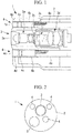
Fig. 1} Fig. 1 is a longitudinal sectional view showing a distal end portion of an endoscope according to an embodiment of the present invention. - {
Fig. 2} Fig. 2 is a front view of the endoscope illustrated inFig. 1 . - {Description of Embodiments}
- An endoscope 1 according to an embodiment of the present invention will be described below with reference to the drawings.
- As shown in
Figs. 1 and 2 , the endoscope 1 according to this embodiment has an observationoptical system 3 and a plurality of illuminationoptical systems 4, and these elements are provided in a distal end portion of the insertedportion 2. In the figures, thereference symbol 5 indicates a channel for a pair of forceps. - The observation
optical system 3 has a plurality of lenses arranged along an optical axis direction, and changes magnification by a structure in which part of the plurality of lenses can be moved in the optical axis direction, and thereby a magnified observation and a normal observation can be switched to each other. - More specifically, the illumination
optical system 3 has, afirst lens group 3a having a positive power, anaperture stop 3b, asecond lens group 3c, and athird lens group 3d having a positive power, which are arranged in this order, and the illuminationoptical system 3 changes the magnified observation state and the normal observation state with each other by moving thesecond lens group 3c in the optical direction. - The illumination
optical system 4 is provided at three positions around the observationoptical system 3 with circumferential intervals therebetween in an example shown inFig. 2 , and has bundles oflight fibers 4a, and threelenses 4b-4d disposed at the radiation ends of the bandles oflight fibers 4a. - The observation
optical system 3 has an optical axis which is substantially parallel to optical axes of the illuminationoptical systems 4, and the most tip side lens surface (first lens surface) 3e is substantially parallel to the most tip side lens surfaces (first lens surfaces) 4e. - The most tip side lens surfaces (first lens surfaces) 4e of the three illumination
optical systems 4 are disposed at a position which is one level lower in the optical axis direction than the most tip side lens surface (first lens surface) 3e of the observationoptical system 3. The level difference between thefirst lens surface 3e and thefirst lens surfaces 4e is called setback dimension D_Back in this embodiment. - In this embodiment, the following expressions (1)-(7) are satisfied.


- In those expressions, D_Back(max) is the maximum value of the setback dimension, D_Back(ave) is the average value of the distances between the
first lens surfaces 4e of all the illuminationoptical systems 4 and thefirst lens surface 3e of the observationoptical system 3, ft is the focal length in a close-distance magnified observation state, fw is the focal length in a normal observation state, w(t) is the field of view when conducting the close-distance magnified observation, and FL_L01 is the focal length of the most tip side lens of the observationoptical system 3. - In a general magnified observation endoscope, the distance between the most tip
side lens surface 3e of an observationoptical system 3 and the object is set to be 2-3 mm or the like, which realizes a desired observation. According to the endoscope 1 of this embodiment, since thefirst lens surfaces 4e of the illuminationoptical systems 4 are disposed at the dented position which is distant from the object relative to thefirst lens surface 3e of the observationoptical system 3, it is possible to reduce unevenness of light distribution relative to a configuration in which the observationoptical system 3 and the illuminationoptical systems 4 are arranged at the same level. - When the condition does not reach the lower limit of the expression (1), the setback dimension of the illumination
optical systems 4 relative to the observationoptical system 3 is not sufficient, and unevenness of light distribution is caused. When the condition exceeds the upper limit of the expression (1), the depth is too much and thereby part of illumination light radiated from the illuminationoptical systems 4 may be blocked by the observationoptical system 3 and the like, which hampers desired light distribution. - Also, when the condition does not reach the lower limit of the expression (2), the magnified observation becomes difficult, the zoom ratio becomes too much, the radial dimension of the observation
optical system 3 becomes large, and it becomes difficult to make the diameter of the distal end of the observationoptical system 3 small, which leads reduction of insertion efficiency. - The expression (4) shows a ratio between the field of view of the observation
optical system 3 and the setback dimension of the illuminationoptical systems 4 relative to the observationoptical system 3, in a state in which the distance between the most tipside lens surface 3e of the observationoptical system 3 and the object is 2 mm. When the condition does not reach the lower limit of the expression (4), the maximum value of the setback dimension is too small and thereby the light distribution cannot be improved. When the condition exceeds the upper limit of the expression (4), the field of view becomes small, and therefore it becomes unnecessary to dispose the illuminationoptical systems 4 at a dented position relative to the observationoptical system 3. - The expression (5) shows a ratio between the focal length of the most tip side lens of the observation
optical system 3 and the setback dimension of the illuminationoptical systems 4 relative to the observationoptical system 3. When the condition does not reach the lower limit of the expression (5), the setback dimension is not sufficient and therefore light distribution is not improved, and when the condition exceeds the upper limit, the negative focal length of the most tip side lens of the observationoptical system 3 is too small, and the field of view becomes too large and thereby light distribution becomes worsened. - Since the endoscope 1 is generally provided with a plurality of illumination
optical systems 4, and since the light distribution of the endoscope 1 is the sum of the illumination light radiated from the plurality of illuminationoptical systems 4, the light distribution is largely effected not only by the maximum value of the setback dimensions of the illuminationoptical systems 4 relative to the observationoptical system 3 but also by the average of the setback dimensions. The expressions (3), (6), and (7) are conditional expressions which are made by replacing the maximum value of the setback dimensions of the expressions (1), (4), and (5) with the average of the setback dimensions. - Since the expressions (1) and (2) are satisfied, this embodiment can afford an advantage of reducing unevenness of light distribution when conducting a close-distance magnified observation, without making the diameter of the inserted
portion 2 of the endoscope 1 large. Also, since the expressions (4) and (5) are satisfied, this embodiment can afford an advantage of suppressing unevenness of light distribution even when the field of view becomes large at the time of conducting the magnified observation. Further, since the expressions (3), (6), and (7) are satisfied, this embodiment can afford an advantage of making light distribution, which is made as sum of illumination light radiated from the plurality of illuminationoptical systems 4, desirable at the time of conducting the magnified observation. - It is preferable that the following expressions (1')-(7') are satisfied, while the expressions (1)-(7) are satisfied in the aforementioned embodiment.


- Further, it is more preferable that the following expressions (1")-(7") are satisfied.


- Next, implemented examples of the endoscope 1 are described below.
- The first implemented example is one whose three illumination
optical systems 4 have the setback dimensions of 0.2 mm, 0.3 mm, and 0.3 mm, respectively. - The second implemented example is one whose three illumination optical systems have the setback dimensions of 0.3 mm, 0.3 mm, and 0.3 mm, respectively.
- Values of the respective constants and values of the expressions (1)-(7) are shown in Table 1.
[Table 1] EXPRESSION IMPLEMENTED EXAMPLE 1 IMPLEMENTED EXAMPLE 2 D_Back(max) 0.4 0.3 D_Back(ave) 0.3 0.3 ft 1.29 1.63 fw 1.00 1.10 w(t) 40.5° 28.6° FL_L01 -1.11 -1.21 EXPRESSION (1) 0.310 0.184 EXPRESSION (2) 1.290 1.480 EXPRESSION (3) 0.233 0.184 EXPRESSION (4) 0.234 0. 275 EXPRESSION (5) -0.361 -0.247 EXPRESSION (6) 0.176 0.275 EXPRESSION (7) -0.270 -0.247 - According to these implemented examples, it can be seen that the expressions (1)-(7) are satisfied.
-
- 1
- endoscope
- 3
- observation optical system
- 3c
- lens
- 3e, 4e
- first lens surface (the most tip side lens surface)
- 4
- illumination optical system
Claims (5)
- An endoscope comprising:an observation optical system capable of changing a magnified observation and a normal observation with each other by moving part of lenses in an optical axis; anda plurality of illumination optical systems which radiate illumination light to an object,wherein a most tip side lens surface of at least one of the illumination optical systems is disposed at a position which is closer to a proximal end side of the endoscope than a most tip side lens surface of the observation optical system, and the following conditional expressions are satisfied,

 ft is a focal length in the close-distance magnified observation state,and fw is a focal length in the normal observation state.
 - The endoscope according to claim 1, wherein the following conditional expression is satisfied,

- The endoscope according to claim 1 or 2, wherein the following conditional expressions are satisfied,


- The endoscope according to claim 3, wherein the following conditional expressions are satisfied.


- The endoscope according to claim 3, wherein the most tip side lens surface of the observation optical system and the most tip side lens surfaces of all the illumination optical systems are substantially parallel.
Applications Claiming Priority (2)
| Application Number | Priority Date | Filing Date | Title |
|---|---|---|---|
| JP2014080954 | 2014-04-10 | ||
| PCT/JP2015/061037 WO2015156337A1 (en) | 2014-04-10 | 2015-04-08 | Endoscope |
Publications (2)
| Publication Number | Publication Date |
|---|---|
| EP3130274A1 true EP3130274A1 (en) | 2017-02-15 |
| EP3130274A4 EP3130274A4 (en) | 2017-12-20 |
Family
ID=54287909
Family Applications (1)
| Application Number | Title | Priority Date | Filing Date |
|---|---|---|---|
| EP15776534.8A Withdrawn EP3130274A4 (en) | 2014-04-10 | 2015-04-08 | Endoscope |
Country Status (5)
| Country | Link |
|---|---|
| US (1) | US9757012B2 (en) |
| EP (1) | EP3130274A4 (en) |
| JP (1) | JP5953444B2 (en) |
| CN (1) | CN106102546B (en) |
| WO (1) | WO2015156337A1 (en) |
Families Citing this family (4)
| Publication number | Priority date | Publication date | Assignee | Title |
|---|---|---|---|---|
| EP3184022A4 (en) * | 2014-08-22 | 2018-05-16 | Olympus Corporation | Endscope device |
| JPWO2018179792A1 (en) * | 2017-03-31 | 2019-11-07 | Hoya株式会社 | Endoscope |
| WO2018179791A1 (en) * | 2017-03-31 | 2018-10-04 | Hoya株式会社 | Endoscope |
| WO2020089967A1 (en) | 2018-10-29 | 2020-05-07 | オリンパス株式会社 | Endoscope |
Family Cites Families (19)
| Publication number | Priority date | Publication date | Assignee | Title |
|---|---|---|---|---|
| JP2876252B2 (en) * | 1990-10-17 | 1999-03-31 | オリンパス光学工業株式会社 | Endoscope objective lens |
| JP3477314B2 (en) | 1996-05-17 | 2003-12-10 | オリンパス株式会社 | Endoscope lighting system |
| JPH10239740A (en) * | 1997-02-28 | 1998-09-11 | Toshiba Corp | Endoscope device |
| US6251068B1 (en) * | 1998-05-18 | 2001-06-26 | Fuji Photo Optical Co., Ltd. | Endoscopic observation system |
| JP2001166223A (en) * | 1999-12-03 | 2001-06-22 | Olympus Optical Co Ltd | Endoscope |
| JP2001346752A (en) * | 2000-06-09 | 2001-12-18 | Asahi Optical Co Ltd | Endoscope for close-up magnification observation |
| JP4727959B2 (en) * | 2004-09-03 | 2011-07-20 | オリンパス株式会社 | Endoscope optical system |
| JP2006320367A (en) * | 2005-05-17 | 2006-11-30 | Olympus Medical Systems Corp | End of the endoscope |
| JP4875319B2 (en) * | 2005-06-20 | 2012-02-15 | オリンパスメディカルシステムズ株式会社 | Endoscope |
| JP4668831B2 (en) | 2006-04-24 | 2011-04-13 | オリンパスメディカルシステムズ株式会社 | Endoscope |
| JP5030507B2 (en) * | 2006-08-30 | 2012-09-19 | オリンパスメディカルシステムズ株式会社 | Endoscope tip hood and endoscope with hood |
| CN102316783B (en) * | 2009-03-31 | 2015-12-02 | 奥林巴斯株式会社 | endoscope |
| JP4834799B2 (en) * | 2009-05-26 | 2011-12-14 | オリンパスメディカルシステムズ株式会社 | Endoscope objective lens |
| JP5343066B2 (en) * | 2010-12-15 | 2013-11-13 | 富士フイルム株式会社 | Endoscope device |
| JP5292428B2 (en) * | 2011-03-22 | 2013-09-18 | 富士フイルム株式会社 | Endoscope system |
| CN103460111B (en) * | 2011-12-01 | 2016-12-14 | 奥林巴斯株式会社 | Endoscope apparatus |
| WO2013105376A1 (en) * | 2012-01-13 | 2013-07-18 | オリンパスメディカルシステムズ株式会社 | Endoscope tip component and endoscope |
| EP3000378B1 (en) * | 2013-05-22 | 2017-11-22 | Olympus Corporation | Endoscope |
| EP3096176A4 (en) * | 2014-01-15 | 2018-01-03 | Olympus Corporation | Endoscope device |
-
2015
- 2015-04-08 CN CN201580012876.0A patent/CN106102546B/en active Active
- 2015-04-08 WO PCT/JP2015/061037 patent/WO2015156337A1/en not_active Ceased
- 2015-04-08 JP JP2015554379A patent/JP5953444B2/en active Active
- 2015-04-08 EP EP15776534.8A patent/EP3130274A4/en not_active Withdrawn
-
2016
- 2016-08-29 US US15/250,209 patent/US9757012B2/en active Active
Also Published As
| Publication number | Publication date |
|---|---|
| JPWO2015156337A1 (en) | 2017-04-13 |
| EP3130274A4 (en) | 2017-12-20 |
| US20160367113A1 (en) | 2016-12-22 |
| CN106102546B (en) | 2018-05-04 |
| CN106102546A (en) | 2016-11-09 |
| JP5953444B2 (en) | 2016-07-20 |
| WO2015156337A1 (en) | 2015-10-15 |
| US9757012B2 (en) | 2017-09-12 |
Similar Documents
| Publication | Publication Date | Title |
|---|---|---|
| EP3130274A1 (en) | Endoscope | |
| EP3205253B1 (en) | Endoscope | |
| EP3132735A1 (en) | Capsule endoscope | |
| EP2804036A1 (en) | Endoscope tip component and endoscope | |
| US10130245B2 (en) | Endoscope apparatus | |
| EP2899580A1 (en) | Endoscope objective lens | |
| WO2009089538A3 (en) | Grin lens microscope system | |
| JP5711436B1 (en) | Endoscope | |
| EP4220265A3 (en) | Lens structure, lens structure fabrication method, and camera | |
| EP3282299A1 (en) | Endoscope objective optical system | |
| JP5942063B1 (en) | Endoscope device | |
| EP3168669A1 (en) | Endoscope objective optical system | |
| US11092797B2 (en) | Endoscopic image capturing device | |
| CN106461917A (en) | optical lens | |
| KR101404611B1 (en) | endoscope optical system | |
| US10667672B2 (en) | Endoscope | |
| EP2565695A1 (en) | Projection lens | |
| US10786142B2 (en) | Surgical instrument having working channels, each having a profile edge | |
| US20160054557A1 (en) | Rigid endoscope | |
| US7448994B2 (en) | Endoscope | |
| US10111579B2 (en) | Endoscope having an illumination system shifted with respect to an imaging system to reduce generation of heat at a front-end portion of the endoscope | |
| US12446763B2 (en) | Endoscope | |
| US10620424B1 (en) | Lens for use with imaging sensors | |
| CN107561678B (en) | Operation microscope camera optical system | |
| Shadfan et al. | Design and fabrication of miniature objective lens for laser ablation surgery probe |
Legal Events
| Date | Code | Title | Description |
|---|---|---|---|
| STAA | Information on the status of an ep patent application or granted ep patent |
Free format text: STATUS: THE INTERNATIONAL PUBLICATION HAS BEEN MADE |
|
| PUAI | Public reference made under article 153(3) epc to a published international application that has entered the european phase |
Free format text: ORIGINAL CODE: 0009012 |
|
| STAA | Information on the status of an ep patent application or granted ep patent |
Free format text: STATUS: REQUEST FOR EXAMINATION WAS MADE |
|
| 17P | Request for examination filed |
Effective date: 20161014 |
|
| AK | Designated contracting states |
Kind code of ref document: A1 Designated state(s): AL AT BE BG CH CY CZ DE DK EE ES FI FR GB GR HR HU IE IS IT LI LT LU LV MC MK MT NL NO PL PT RO RS SE SI SK SM TR |
|
| AX | Request for extension of the european patent |
Extension state: BA ME |
|
| DAV | Request for validation of the european patent (deleted) | ||
| DAX | Request for extension of the european patent (deleted) | ||
| A4 | Supplementary search report drawn up and despatched |
Effective date: 20171120 |
|
| RIC1 | Information provided on ipc code assigned before grant |
Ipc: G02B 23/26 20060101ALI20171114BHEP Ipc: A61B 1/06 20060101ALI20171114BHEP Ipc: A61B 1/07 20060101ALI20171114BHEP Ipc: G02B 23/24 20060101ALI20171114BHEP Ipc: A61B 1/00 20060101AFI20171114BHEP |
|
| GRAP | Despatch of communication of intention to grant a patent |
Free format text: ORIGINAL CODE: EPIDOSNIGR1 |
|
| STAA | Information on the status of an ep patent application or granted ep patent |
Free format text: STATUS: GRANT OF PATENT IS INTENDED |
|
| INTG | Intention to grant announced |
Effective date: 20180620 |
|
| STAA | Information on the status of an ep patent application or granted ep patent |
Free format text: STATUS: THE APPLICATION IS DEEMED TO BE WITHDRAWN |
|
| 18D | Application deemed to be withdrawn |
Effective date: 20181101 |