EP3130256B1 - Pillow - Google Patents
Pillow Download PDFInfo
- Publication number
- EP3130256B1 EP3130256B1 EP16183740.6A EP16183740A EP3130256B1 EP 3130256 B1 EP3130256 B1 EP 3130256B1 EP 16183740 A EP16183740 A EP 16183740A EP 3130256 B1 EP3130256 B1 EP 3130256B1
- Authority
- EP
- European Patent Office
- Prior art keywords
- elastic member
- bridging section
- wing
- connecting means
- pillow
- Prior art date
- Legal status (The legal status is an assumption and is not a legal conclusion. Google has not performed a legal analysis and makes no representation as to the accuracy of the status listed.)
- Active
Links
Images



Classifications
-
- A—HUMAN NECESSITIES
- A47—FURNITURE; DOMESTIC ARTICLES OR APPLIANCES; COFFEE MILLS; SPICE MILLS; SUCTION CLEANERS IN GENERAL
- A47C—CHAIRS; SOFAS; BEDS
- A47C16/00—Stand-alone rests or supports for feet, legs, arms, back or head
-
- A—HUMAN NECESSITIES
- A47—FURNITURE; DOMESTIC ARTICLES OR APPLIANCES; COFFEE MILLS; SPICE MILLS; SUCTION CLEANERS IN GENERAL
- A47C—CHAIRS; SOFAS; BEDS
- A47C7/00—Parts, details, or accessories of chairs or stools
- A47C7/36—Supports for the head or the back
- A47C7/38—Supports for the head or the back for the head, e.g. detachable
- A47C7/383—Detachable or loose head- or neck-supports, e.g. horse-shoe shaped
-
- A—HUMAN NECESSITIES
- A47—FURNITURE; DOMESTIC ARTICLES OR APPLIANCES; COFFEE MILLS; SPICE MILLS; SUCTION CLEANERS IN GENERAL
- A47G—HOUSEHOLD OR TABLE EQUIPMENT
- A47G9/00—Bed-covers; Counterpanes; Travelling rugs; Sleeping rugs; Sleeping bags; Pillows
- A47G9/10—Pillows
- A47G9/1081—Pillows comprising a neck support, e.g. a neck roll
Definitions
- the present invention relates to pillows, and more particularly to travel pillows.
- U-shaped pillows are well known and are a familiar sight at airports. Such pillows are provided with two wings and a bridging section connecting the wings, so that the pillow can be wrapped around the back and sides of the neck of the user to support the user's head.
- U-shaped pillows suffer from the problem that the wings tend to splay during use, which means that the wings do not provide sufficient support for the head of the user.
- One solution has been to provide a strap between the free ends of the wings, so that the strap can be fastened during use to prevent the wings splaying and to bring the free ends of the wings together to support the head.
- Pillows of this type typically use a strap with a hook-and-loop arrangement (for example Velcro®) or a clip, buckle or toggle fastener to fasten the strap.
- the present invention aims to provide an improved pillow.
- the present invention provides a pillow comprising two wings; a bridging section connecting the wings so that the wings and bridging section form a substantially U-shaped shape; an elastic member; and connecting means for connecting one portion of the elastic member to a fixing point on a wing or the bridging section and another portion of the elastic member to a fixing point on a wing or the bridging section, so that the elastic member, or the connecting means, or both, can pass from one wing to the other and the elastic member can urge the wings towards one another, wherein, when the portions of the elastic member are connected to a wing or the bridging section by the connecting means, at least a part of the elastic member is provided within a wing or the bridging section or both so that the elastic member can slidably retract into a wing or the bridging section or both.
- the user can lengthen the elastic member or combination of elastic member and connecting means passing from one wing to the other by simply pulling on the elastic member or connecting means.
- the elastic member will then stretch and the wings can be splayed so that the pillow can be wrapped around the back and sides of the user's neck.
- the user can then stop pulling and the elastic member will return to its original length and will urge the wings towards one another in order to support the head.
- the present invention thus provides a more convenient and quicker way of lengthening the elastic member or connecting means passing from one wing to the other.
- the elastic member or connecting means When the elastic member or connecting means passes from one wing to the other, the elastic member is under tension.
- the elastic member or connecting means is capable of being disconnected from at least one fixing point so that the elastic member or connecting means does not pass from one wing to the other.
- the tension in the elastic member shortens the elastic member and draws back any part of the connecting means still connected to the elastic member.
- a shorter length of material is left, leading to a neater arrangement of the pillow when not in use.
- An advantage of connecting a portion of the elastic member to the bridging section rather than the wing is that it allows a long elastic member to be used, provided that the elastic member or connecting means passes around or through the tip of a wing before passing from that wing to the other.
- a longer elastic member is typically able to extend more than a shorter one.
- the elastic member is preferably made from a material having a low extension stiffness.
- the material may have a Young's modulus of less than or equal to 0.1 GPa, more preferably, less than or equal to 0.05 GPa, more preferably, less than or equal to 0.01 GPa, at small strains.
- the elastic member is made from an elastomeric material such as rubber.
- the elastic member is made from a woven elastic, preferably polyester woven elastic.
- the elastic member is stretchable to at least 40% of its original length, more preferably at least 60% of its original length, more preferably still at least 80% of its original length, more preferably still at least 100% of its original length.
- the elastic member has an equivalent spring constant of less than 500N/m. That is to say, the elastic member extends by at least 1cm under a load of 5N, the elastic member having an original length of 13cm. More preferably, the elastic member has a spring constant of between 100N/m and 500N/m.
- the elastic member is resilient.
- the elastic member once stretched, acts like a spring to spring back to its unstretched state.
- the material may have a modulus of resilience of greater than 0.7 Mpa, more preferably greater than 1.4 MPa, more preferably greater than 2.1 MPa.
- the elastic member between the portions, or the connecting means, or both can pass from one wing to the other away from the bridging section, preferably at the tips of the wings.
- the user can make the connection between the portions of the elastic member and a wing or the bridging section by way of a fastener.
- the user can disconnect the portions of the elastic member from a wing or the bridging section by way of a fastener.
- the portions of the elastic member are connected to a wing or the bridging section by the connecting means, at least a part of the elastic member is provided within a wing or the bridging section or both.
- the elastic member may be so provided when it is in a stretched or unstretched state.
- At least a part of the elastic member that is so provided within a wing or the bridging section or both may be provided within a sleeve, for example a polyester sleeve.
- the sleeve provides two layers of a sandwich structure with the elastic member between the two layers.
- the sleeve allows the elastic member to slide easily back and forth because of low friction between the elastic member and sleeve. Polyester is particularly suitable for this.
- polyester material may be provided only on one side of the elastic member, for example on the inside of the elastic member, or on the outside of the elastic member, with respect to the space between the wings that is adjacent to the bridging section.
- At least a part of the elastic member is provided within a wing or the bridging section or both so that the elastic member can slide within a wing or the bridging section or both.
- the sliding arrangement provides a convenient use of space.
- the portions of the elastic member are (or are not) connected to a wing or the bridging section by the connecting means, the whole of the elastic member is provided within a wing or the bridging section or both. This may be the case when the elastic member is in a stretched or unstretched state.
- the pillow comprises a stop to prevent any portion of the elastic member leaving a wing or the bridging section, for example due to urging of the connecting means by the user.
- a stop to prevent any portion of the elastic member leaving a wing or the bridging section, for example due to urging of the connecting means by the user.
- the whole of the elastic member is retained in a wing or the bridging section or both. This can prevent damage to the elastic member and also keeps the elastic member, which may be unsightly, hidden.
- the whole of the elastic member is provided within a wing or the bridging section or both so that the elastic member can slide within a wing or the bridging section or both.
- the sliding arrangement provides a convenient use of space.
- the elastic member comprises or is a strap.
- the preferable features herein described with reference to the elastic member are equally applicable to the strap of the elastic member.
- the portions of the elastic member are connected to a wing or the bridging section by the connecting means, at least a part of the strap of the elastic member is provided within a wing or the bridging section or both.
- the whole of the strap of the elastic member is provided within a wing or the bridging section or both.
- the elastic member is in a stretched or unstretched state, for example when urged by a user or not urged by a user, or when the portions of the elastic member are connected to a wing or the bridging section by the connecting means, or conversely when the portions are disconnected.
- the connecting means when the portions of the elastic member are (or are not) connected to a wing or the bridging section by the connecting means, at least a portion of the connecting means is provided within a wing or the bridging section or both.
- This may be the case when the elastic member is in a stretched or unstretched state, for example when urged by a user or when not urged by a user, or when the portions of the elastic member are connected to a wing or the bridging section by the connecting means, or conversely when the portions are disconnected.
- At least a portion of the connecting means that is so provided within a wing or the bridging section or both may be provided within a sleeve, for example a polyester sleeve.
- a sleeve for example a polyester sleeve.
- the sleeve provides two layers of a sandwich structure with the connecting means between the two layers.
- the sleeve allows the connecting means to slide easily back and forth because of low friction between the connecting means and sleeve. Polyester is particularly suitable for this.
- polyester material may be provided only on one side of the connecting means, for example on the inside of the connecting means, or on the outside of the connecting means, with respect to the space between the wings that is adjacent to the bridging section.
- the connecting means comprises a strap.
- the preferable features herein described with reference to the connecting means are equally applicable to the strap of the connecting means.
- the connecting means when the portions of the elastic member are connected to a wing or the bridging section by the connecting means, at least a part, more preferably the whole, of the strap of the connecting means is provided within a wing or the bridging section or both.
- the elastic member, the connecting means or the strap of the connecting means comprises at least two parts which can be disconnected from one another.
- the parts can be disconnected by means of a fastener such as a hook-and-loop arrangement, or a clip, buckle or toggle fastener or the like.
- a fastener such as a hook-and-loop arrangement, or a clip, buckle or toggle fastener or the like.
- the elastic member may be disconnectable from the connecting means.
- the elastic member is provided adjacent to a fixing point. This means that, when at least a portion of the elastic member is within a wing or bridging section in the unstretched state, a longer elastic member can be used without being exposed than when the elastic member is provided away from the fixing point.
- the connecting means comprises an additional elastic member.
- additional elastic member for the avoidance of doubt, the preferable features herein described with reference to the elastic member referred to hereinbefore are equally applicable to additional elastic member.
- the fixing points are at different points on a wing or the bridging section
- the pillow comprises a reinforcing member or a gripping member that is fixed to a wing or the bridging section at the fixing points.
- the fixing points may be at the same point on a wing or the bridging section.
- the reinforcing member provides stable fixing points to which the elastic member can be connected.
- the reinforcing member may also increase the resistance to bending of a wing or the bridging section: the resistance to bending of the wing or the bridging section to which the reinforcing member is fixed is greater than without the reinforcing member.
- the reinforcing member is rigid. That is to say, the resistance to bending of the reinforcing member in a direction that moves the wings towards or away from each other is greater than that of the bridging section.
- the reinforcing member is substantially inextensible.
- the reinforcing member comprises elastomeric material, more preferably a thermoplastic elastomer.
- the reinforcing member is elongate.
- the reinforcing member is made from a material having a low extension stiffness.
- the material may have a Young's modulus of less than or equal to 0.1 GPa, more preferably, less than or equal to 0.05 GPa, more preferably, less than or equal to 0.01 GPa, at small strains.
- the reinforcing member is resilient. This means that when the pillow is deformed for example by moving the wings towards or away from each other, the reinforcing member tends to return the wings to the position before deformation occurred.
- the fixing points are different, i.e. the connecting means is fixed at different points.
- the fixing points are both on the bridging section.
- a fixing point is adjacent to a wing.
- each fixing point is adjacent to a respective wing.
- the fixing points are adjacent to the reinforcing member.
- the substantially U-shaped shape is formed in plan view, and the bridging section has an outer peripheral surface in plan view, and the reinforcing member is provided on the outer peripheral surface of the bridging section.
- “Outer” here means outer with respect to the centre of the substantially U-shaped shape in plan view.
- the reinforcing member is fixed to the bridging section and provided along the outer peripheral surface of the bridging section, to restrain deformation of the bridging section.
- the reinforcing member may be provided on or below the outer peripheral surface, and the reinforcing member may or may not contact the peripheral surface.
- the pillow comprises a stop for limiting movement, for example stretching, of the elastic member or connecting means.
- Two stops may be provided, one for limiting movement of the elastic member, and the other for limiting movement of the connecting means.
- the movement is due to urging by the elastic member, for example when the elastic member tends to return to its unstretched state.
- the stop may, for example, prevent an end of the elastic member being retracting into a wing or the bridging section.
- the movement may be due to urging by the user, for example when the user pulls the connecting means.
- the stop can, for example, prevent the elastic member being stretched past its elastic limit.
- the stop may be provided at the point that the elastic member or connecting means can pass out of a wing or the bridging section.
- the stop may be adapted to catch a holding portion of the connecting means or elastic member, for example an end.
- the stop comprises a gate adapted to catch a holding portion of the connecting means or elastic member.
- the gate may be provided to allow the connecting means to pass out of a wing or the bridging section.
- the gate is adapted to catch the holding portion once the whole of a strap of the connecting means is within a wing or the bridging section.
- the whole of the elastic member is also within a wing or the bridging section.
- the gate is adapted to catch the holding portion when the whole of a strap of the connecting means has passed out of a wing or the bridging section.
- a buckle is provided to allow parts of the connecting means or elastic member to be disconnected, and preferably the buckle provides the holding portion.
- the connecting means or elastic member comprises a strap
- the holding portion is at one end of the strap.
- the holding portion can be caught once the strap has been fully retracted.
- the elastic member when the holding portion is caught in the gate thereby limiting movement of the elastic member or connecting means due to urging by the elastic member, the elastic member continues to urge the holding portion towards the gate. In this case, the elastic remains under tension. This arrangement ensures that any portion of the elastic member or connecting means that has already been retracted remains fully retracted.
- the substantially U-shaped shape is formed in plan view, and each of the wings has an outer peripheral side surface in plan view, and, when the portions of the elastic member are connected to a wing or the bridging section by the connecting means, at least a part of the elastic member or connecting means is provided adjacent to, for example on or below, the outer peripheral side surface of a wing.
- the effect of providing at least a portion of the elastic member or connecting means adjacent to the outer peripheral side surface of a wing is as follows. There is friction between the elastic member or connecting means and the wing when the elastic member is connected to a wing or the bridging section by the connecting means. This friction opposes the elastic force of the elastic member. This means that, after the wings have been pulled apart by the user, the friction restrains the restoring force in the elastic member from pulling the wings together. Therefore, the relative position of the wings can, to a certain extent, be adjusted simply by pulling them apart.
- the at least a portion of the elastic member or connecting means that is adjacent to the outer peripheral side surface of a wing is provided adjacent the bridging section, and preferably at the midpoint between bridging section and wing tip.
- the at least a portion is provided at the midpoint between the top surface and bottom surface of the wing in elevation view.
- the at least a portion runs along the peripheral side surface at the midpoint between the top surface and bottom surface.
- the elastic member or connecting means runs around a wing tip when the elastic member is connected to a wing or the bridging section by the connecting means.
- the substantially U-shaped shape is formed in plan view, and the bridging section has an outer peripheral surface in plan view, and, when the portions of the elastic member are connected to a wing or the bridging section by the connecting means, at least a part of the elastic member or connecting means is provided adjacent to, for example on or below, the outer peripheral surface of the bridging section.
- the surface of a wing or the bridging section comprises a layer of fabric.
- a wing or the bridging section has a filling of foam, advantageously memory foam.
- the wings and bridging section are filled with a single piece of memory foam.
- the elastic member or connecting means is provided below a layer of fabric forming the surface of a wing or the bridging section.
- the elastic member or connecting means is provided between two layers of fabric forming the surface of a wing or the bridging section. The two layers of fabric may provide a slot in which the elastic member or connecting means can slide.
- the thickness of the thinnest portion of the bridging section is less than the thickness of the thickest portion of the wings, and preferably less than the thinnest portion of the wings. This arrangement prevents the head of the user being pushed too far away from the surface on which the pillow is placed.
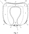
- a pillow 1 comprises two wings 2, 3 and a bridging section 4 connecting the wings 2, 3 so that the wings 2, 3 and bridging section 4 form a substantially U-shaped shape.
- the pillow 1 also comprises a first elastic member, which is not shown in Figure 1 .
- the whole of the first elastic member is at all times provided within the wing 2 and the bridging section 4.
- the pillow 1 further comprises connecting means 5 which connect one portion of the first elastic member to a first fixing point FP1 on the bridging section 4 and another portion of the first elastic member to a second fixing point FP2 on the bridging section 4, so that the connecting means 5 can pass from wing 2 to wing 3 and the first elastic member can urge the wings towards one another.
- the wings 2, 3 are divided from the bridging section 4 by line L.
- the pillow is shown ready for use in that the connecting means 5 is shown already connecting one portion of the first elastic member to the first fixing point FP1 and another portion of the first elastic member to the second fixing point FP2.
- the first elastic member is provided adjacent the first fixing point FP1.
- the connecting means 5 comprises a first strap 10, a buckle 12, a second strap 11 and a second elastic member.
- the second elastic member is not shown in Figure 1 . In the preferred embodiment, the whole of the second elastic member is at all times provided within the wing 3 and the bridging section 4.
- the first and second straps 10 and 11 are made of polyester.
- the dimensions of each of the first and second straps 10, 11 are approximately as follows: total length is 160mm; width is 19mm; thickness is 1mm.
- the first elastic member and second elastic member are provided within respective polyester sleeves.
- One sleeve is provided on the outside of the wing 2 and bridging section 4, and the other sleeve is provided on the outside of the wing 3 and bridging section 4.
- the sleeves allow the elastic members to slide easily within them.
- the first and second elastic members are respective straps.
- the connecting means 5 further comprises stitching which connects one end of the first elastic member to the bridging section 4 at the first fixing point FP1, and stitching which connects one end of the second elastic member to the bridging section 4 at the second fixing point FP2.
- the other end of the first elastic member is fixed to one end of the first strap 10.
- the other end of the first strap 10 is fixed to one end of the buckle 12.
- the other end of the buckle 12 is fixed to one end of the second strap 11.
- the other end of the second strap 11 is fixed to one end of the second elastic member, which is the end that is not connected to the second fixing point FP2 by stitching.
- the buckle 12 has two parts, namely a male part and a female part.
- the male part is fixed to the first strap 10 and the female part is fixed to second strap 11.
- Fig. 1 the pillow is shown in the "in use” position, that is to say the position it would take when being used and when wrapped around the neck of the user.
- the user's neck prevents the tips of the wings 2, 3 from touching.
- the male part of buckle 12 is snap-fitted into the female part to fasten the respective ends of the straps 10, 11 together.
- the first and second elastic members have been stretched from their unstretched position and are in their stretched position. The tension in the first and second elastic members urges the wings 2, 3 towards one another.
- the tips of the wings 2, 3 may touch due to urging by the first and second elastic members.
- Gates 13, 14 are provided on wings 2, 3, respectively.
- the gates 13, 14 are provided to allow the first and second straps 10, 11, respectively, to pass out of the first and second wings, 2, 3, respectively.
- the gates 13, 14 are made of rubber.
- the substantially U-shaped shape is formed in plan view.
- the bridging section 4 has an outer peripheral surface, which is outer with respect to the centre of the substantially U-shaped shape in plan view.
- the bridging section 4 also has an inner peripheral surface, which is inner with respect to the centre of the substantially U-shaped shape in plan view.
- a rigid reinforcing and gripping member in the form of a plate 6 is provided on, along and fixed to the outer peripheral surface of the bridging section 4.
- the plate 6 is rigid, which is to say the resistance to bending of the plate 6 in a direction that moves the wings 2, 3 towards or away from each other is greater than that of the bridging section 4.
- the plate 6 is fixed to the bridging section 4 at the first and second fixing points FP1 and FP2.
- the stitching that connects the first and second elastic members to the first and second fixing points FP1 and FP2 also fixes the plate 6 to the first and second fixing points FP1 and FP2.
- the fixing points FP1 and FP2 are opposite to portions of the bridging section 4 to which wings 2, 3 are connected.
- the deflection of the wings 2, 3 of the pillow 1 of the present embodiment was measured to determine the effect of the plate 6.
- the other end of plate 6 was found to deflect by about 4cm due to self-weight of the pillow 1.
- the corresponding deflection was found to be about 12cm due to self-weight of the filling.
- the plate 6 performs several functions: firstly, the plate 6 provides grip between the bridging section 6 and a surface which the bridging section 6 contacts; secondly, the plate 6 limits deformation of the bridging section; and thirdly, the plate 6 provides stable fixing points to which the first and second elastic members can be connected.
- the plate 6 is formed of an elastomeric material, namely a thermoplastic elastomer (TPE).
- TPE thermoplastic elastomer
- a suitable TPE material can be obtained from AIFFU International Limited of Wan Chai, Hong Kong.
- the coefficient of friction between the plate 6 and photocopier paper is about 0.7.
- the plate 6 in the present embodiment is about 205mm long at it longest point, 40mm wide, and 8mm thick at its thickest point.
- the surface of the wings 2, 3 and bridging section 4 comprises a layer of flexible fabric forming a jacket.
- the wings 2, 3 and bridging section 4 are filled with a single piece of memory foam. Stable fixing points are necessary so that the elastic members urge the wings towards one another. Without the plate 6, the elastic members would be fixed only to the flexible fabric jacket, which alone would not provide stable fixing points.
- first and second elastic members and a portion of each of first and second straps 10, 11 are provided between two layers of fabric forming the surface of wings 2, 3, respectively, and between two layers of fabric forming the surface of the bridging section 4.
- the two layers of fabric provide respective slots in which the elastic members and the first and second straps 10, 11 can slide.
- the thickness of the thinnest portion of the bridging section 4, which is at its midpoint, is less than the thickness of the thickest portion of the wings 2, 3, and less than the thinnest portion of the wings 2, 3.
- the tips of the wings 2, 3 are bulbous.
- the wings 2, 3 and bridging section 4 are symmetrical in plan view about a line passing between the tips of wings 2, 3 and through the midpoint of the bridging section 4.
- the plate 6 is symmetrical in plan view about the same line, as are the fixing points FP1, FP2.
- the plate 6 and the fixing points FP1, FP2 are on the rear surface of the bridging section 4. The rear surface faces in a rear direction, away from the tips of the wings 2, 3.
- the top surface of the bridging section 4 forms a V-shape in elevation view.
- Fig. 5 shows the detail of one end of the first elastic member 7 through the fabric jacket and the detail of one end of the plate 6.
- One end of the first elastic member 7 is connected to one end of the plate 6 at the first fixing point FP1 on the outer peripheral surface of the bridging section 4. Strong stitching connects the first elastic member 7 and the plate 6 at the first fixing point FP1.
- One end of the second elastic member 8 is connected to the other end of plate 6 at the second fixing point FP2 in a corresponding manner.
- each of the first and second elastic members 7, 8 in their unstretched state are approximately as follows: total length is 170mm; width is 26mm; thickness is 1.35mm.
- each elastic member 7, 8 has stitching at both of its ends. The length between the stitching at each end of the elastic member 7 is about 130mm, and so this is the length that can stretch.
- the elastic member is made from polyester woven elastic. A suitable polyester woven elastic material can be obtained from Tianao Holdings Limited of Kowloon, Hong Kong. In the present embodiment, the polyester woven elastic is 75% polyester and 25% rubber.
- Fig. 6 shows the other end of the first elastic member 7 which is fixed to one end of the strap 10.
- the first elastic member 7 passes from the bridging section 4 to the wing 2.
- the elastic member passes along the outer peripheral surface of the bridging section from the first fixing point FP1 to the outer peripheral side surface of the wing 2 to the position where it is fixed to the strap 10. From this point the strap 10 passes along the outer peripheral side surface of the wing 2 to the outer peripheral tip surface of the wing 2.
- the strap 10 then leaves the surface of the wing 2 and passes towards the wing 3 until it reaches the buckle 10.
- the second elastic member 8 and the strap 11 are provided on the bridging section 4 and wing 3 in a corresponding manner.
- the whole of the elastic member 7 is provided within the bridging section 4.
- the whole of the elastic member 7 may be provided within both the bridging section 4 and wing 2 in the unstretched position. In the stretched position, however, the whole of the elastic member 7 is provided within both the bridging section 4 and wing 2.
- the second elastic member 8 mutatis mutandis.
- gates 13, 14 are each adapted to catch a holding portion of the connecting means 5, in the present embodiment the male and female parts of the buckle 12, respectively.
- Figs. 7 and 8 for the gate 14 the strap 11 is retracted by the second elastic member 8 and the female part of buckle 12 is caught in gate 14 once the whole of strap 11 has been retracted.
- the male part of buckle 12 is caught in gate 13 in a corresponding manner.
- Fig. 7 shows the two different positions of the female part of buckle 12.
- Fig. 8 shows different stages as the strap 11 is retracted, and shows the different positions of the female part of buckle 12. In the top three stages, the arrow shows the direction of retraction.
- each first and second strap 10, 11 has been retracted into the wings 2, 3, respectively, the male and female parts of the buckle 12 can be grasped and pulled by the user to pull the straps 10 and 11 out of the wings 2, 3 thereby stretching the first and second elastic members 7, 8.
- the gates 13, 14 are also each adapted to catch a holding portion of the connecting means 5 when the whole of each of the first and second straps 10, 11 has passed out of a wings 2, 3, respectively. In the present embodiment, only part of each of the straps 10, 11 have passed out of the wings 2, 3 when the pillow is in the in use position. In the present embodiment, these holding portions are provided at the join between the first elastic member 7 and the first strap 10, and at the join between the second elastic member 8 and the second strap 11. Thus the gates 13, 14 prevent any part of the elastic members leaving the wings 2, 3.
- Figs. 9 and 10 show plate 6 on the rear surface of the bridging section 4.
- the rear surface faces in a rear direction, away from the tips of the wings 2, 3.
- the whole of one surface of the plate 6 contacts the rear surface of the bridging section 4.
- This surface of the plate 6 is fixed around its periphery to the rear surface of the bridging section 4 by stitching.
- the surface of the plate 6 fixed to the rear surface of the bridging section 4 is substantially planar.
- the surface of the plate 6 fixed to the rear surface of the bridging section 4 has a slightly bowed shape with the ends of the surface more rearward than the midpoint of the surface.
- the plate 6 has a peripheral ridge on its rear surface (that is the outer peripheral surface of the plate 6, which is the surface opposite to the surface fixed to the bridging section 4).
- the peripheral ridge is provided around the periphery of the rear surface of the plate 6.
- the peripheral ridge comprises two straight long ridges running in a direction from wing 2 to wing 3, and two short curved ridges joining the two straight ridges at their ends.
- the peripheral ridge is about 2mm high.
- the plate 6 is elongate with its longer dimension running in a direction from wing 2 to wing 3.
- Plate 6 comprises rubber and is substantially inextensible. Plate 6 is also resilient which means that when the pillow 1 is deformed for example by moving the wings 2, 3 towards or away from each other, the plate 6 tends to return the wings 2, 3 to their position before deformation occurred.
- the pillow 1 is not symmetrical about a "horizontal" plane, i.e. a plane that is normal to the direction of view in Fig. 1 .
- the wings 2, 3 each curve upwards and then downwards as the wing extends from the bridging section 4 to the wing tip.
- the top of the bridging section 4 curves downwards in the middle, but the bottom of the bridging section 4 is flat. This shaping makes the pillow more comfortable for the user as it fits the body more snuggly.
Landscapes
- Health & Medical Sciences (AREA)
- General Health & Medical Sciences (AREA)
- Otolaryngology (AREA)
- Pulmonology (AREA)
- Bedding Items (AREA)
- Orthopedics, Nursing, And Contraception (AREA)
Description
- The present invention relates to pillows, and more particularly to travel pillows.
- U-shaped pillows are well known and are a familiar sight at airports. Such pillows are provided with two wings and a bridging section connecting the wings, so that the pillow can be wrapped around the back and sides of the neck of the user to support the user's head.
- Many U-shaped pillows suffer from the problem that the wings tend to splay during use, which means that the wings do not provide sufficient support for the head of the user. One solution has been to provide a strap between the free ends of the wings, so that the strap can be fastened during use to prevent the wings splaying and to bring the free ends of the wings together to support the head. Pillows of this type typically use a strap with a hook-and-loop arrangement (for example Velcro®) or a clip, buckle or toggle fastener to fasten the strap.
- Attention is also drawn to the disclosures of
US2015/082546 ,US2015/157134 ,KR2012-0006946 US9657462 US2015/059098 . - The present invention aims to provide an improved pillow.
- The present invention provides a pillow comprising two wings; a bridging section connecting the wings so that the wings and bridging section form a substantially U-shaped shape; an elastic member; and connecting means for connecting one portion of the elastic member to a fixing point on a wing or the bridging section and another portion of the elastic member to a fixing point on a wing or the bridging section, so that the elastic member, or the connecting means, or both, can pass from one wing to the other and the elastic member can urge the wings towards one another, wherein, when the portions of the elastic member are connected to a wing or the bridging section by the connecting means, at least a part of the elastic member is provided within a wing or the bridging section or both so that the elastic member can slidably retract into a wing or the bridging section or both.
- When the user wishes to use the pillow of the present invention, the user can lengthen the elastic member or combination of elastic member and connecting means passing from one wing to the other by simply pulling on the elastic member or connecting means. The elastic member will then stretch and the wings can be splayed so that the pillow can be wrapped around the back and sides of the user's neck. The user can then stop pulling and the elastic member will return to its original length and will urge the wings towards one another in order to support the head. The present invention thus provides a more convenient and quicker way of lengthening the elastic member or connecting means passing from one wing to the other.
- When the elastic member or connecting means passes from one wing to the other, the elastic member is under tension. Preferably, the elastic member or connecting means is capable of being disconnected from at least one fixing point so that the elastic member or connecting means does not pass from one wing to the other. Upon such disconnection, for example after use, the tension in the elastic member shortens the elastic member and draws back any part of the connecting means still connected to the elastic member. Thus a shorter length of material is left, leading to a neater arrangement of the pillow when not in use.
- An advantage of connecting a portion of the elastic member to the bridging section rather than the wing is that it allows a long elastic member to be used, provided that the elastic member or connecting means passes around or through the tip of a wing before passing from that wing to the other. A longer elastic member is typically able to extend more than a shorter one.
- The elastic member is preferably made from a material having a low extension stiffness. For example, the material may have a Young's modulus of less than or equal to 0.1 GPa, more preferably, less than or equal to 0.05 GPa, more preferably, less than or equal to 0.01 GPa, at small strains. Suitably, the elastic member is made from an elastomeric material such as rubber. Suitably, the elastic member is made from a woven elastic, preferably polyester woven elastic. Preferably, the elastic member is stretchable to at least 40% of its original length, more preferably at least 60% of its original length, more preferably still at least 80% of its original length, more preferably still at least 100% of its original length.
- Preferably, the elastic member has an equivalent spring constant of less than 500N/m. That is to say, the elastic member extends by at least 1cm under a load of 5N, the elastic member having an original length of 13cm. More preferably, the elastic member has a spring constant of between 100N/m and 500N/m.
- Preferably, the elastic member is resilient. Thus, the elastic member, once stretched, acts like a spring to spring back to its unstretched state. For example, the material may have a modulus of resilience of greater than 0.7 Mpa, more preferably greater than 1.4 MPa, more preferably greater than 2.1 MPa.
- Preferably, the elastic member between the portions, or the connecting means, or both, can pass from one wing to the other away from the bridging section, preferably at the tips of the wings.
- Preferably, the user can make the connection between the portions of the elastic member and a wing or the bridging section by way of a fastener. Preferably, the user can disconnect the portions of the elastic member from a wing or the bridging section by way of a fastener.
- In the present invention, when the portions of the elastic member are connected to a wing or the bridging section by the connecting means, at least a part of the elastic member is provided within a wing or the bridging section or both. The elastic member may be so provided when it is in a stretched or unstretched state.
- This provides the advantage that the elastic member and possibly the connecting means can retract into the wing or bridging section, as the case may be, once tension has been removed from the elastic member.
- At least a part of the elastic member that is so provided within a wing or the bridging section or both may be provided within a sleeve, for example a polyester sleeve. Preferably, the sleeve provides two layers of a sandwich structure with the elastic member between the two layers. The sleeve allows the elastic member to slide easily back and forth because of low friction between the elastic member and sleeve. Polyester is particularly suitable for this.
- Alternatively, polyester material may be provided only on one side of the elastic member, for example on the inside of the elastic member, or on the outside of the elastic member, with respect to the space between the wings that is adjacent to the bridging section.
- In the present invention, at least a part of the elastic member is provided within a wing or the bridging section or both so that the elastic member can slide within a wing or the bridging section or both. The sliding arrangement provides a convenient use of space.
- Preferably, when the portions of the elastic member are (or are not) connected to a wing or the bridging section by the connecting means, the whole of the elastic member is provided within a wing or the bridging section or both. This may be the case when the elastic member is in a stretched or unstretched state.
- Preferably, the pillow comprises a stop to prevent any portion of the elastic member leaving a wing or the bridging section, for example due to urging of the connecting means by the user. Thus, whether in a stretched or unstretched state, the whole of the elastic member is retained in a wing or the bridging section or both. This can prevent damage to the elastic member and also keeps the elastic member, which may be unsightly, hidden.
- Advantageously, the whole of the elastic member is provided within a wing or the bridging section or both so that the elastic member can slide within a wing or the bridging section or both. The sliding arrangement provides a convenient use of space.
- Advantageously, the elastic member comprises or is a strap. For the avoidance of doubt, the preferable features herein described with reference to the elastic member are equally applicable to the strap of the elastic member.
- Preferably, when the portions of the elastic member are connected to a wing or the bridging section by the connecting means, at least a part of the strap of the elastic member is provided within a wing or the bridging section or both.
- Preferably, when the portions of the elastic member are (or are not) connected to a wing or the bridging section by the connecting means, the whole of the strap of the elastic member is provided within a wing or the bridging section or both. This may be the case when the elastic member is in a stretched or unstretched state, for example when urged by a user or not urged by a user, or when the portions of the elastic member are connected to a wing or the bridging section by the connecting means, or conversely when the portions are disconnected.
- Preferably, when the portions of the elastic member are (or are not) connected to a wing or the bridging section by the connecting means, at least a portion of the connecting means is provided within a wing or the bridging section or both. This may be the case when the elastic member is in a stretched or unstretched state, for example when urged by a user or when not urged by a user, or when the portions of the elastic member are connected to a wing or the bridging section by the connecting means, or conversely when the portions are disconnected.
- At least a portion of the connecting means that is so provided within a wing or the bridging section or both may be provided within a sleeve, for example a polyester sleeve. Preferably, the sleeve provides two layers of a sandwich structure with the connecting means between the two layers. The sleeve allows the connecting means to slide easily back and forth because of low friction between the connecting means and sleeve. Polyester is particularly suitable for this.
- Alternatively, polyester material may be provided only on one side of the connecting means, for example on the inside of the connecting means, or on the outside of the connecting means, with respect to the space between the wings that is adjacent to the bridging section.
- Preferably, the connecting means comprises a strap. For the avoidance of doubt, the preferable features herein described with reference to the connecting means are equally applicable to the strap of the connecting means.
- Preferably, when the portions of the elastic member are connected to a wing or the bridging section by the connecting means, at least a part, more preferably the whole, of the strap of the connecting means is provided within a wing or the bridging section or both.
- Preferably, the elastic member, the connecting means or the strap of the connecting means comprises at least two parts which can be disconnected from one another. For example, the parts can be disconnected by means of a fastener such as a hook-and-loop arrangement, or a clip, buckle or toggle fastener or the like. Thus, if the elastic member does not stretch sufficiently to allow the wings to splay while the pillow is wrapped around the user's neck, the parts can be disconnected to allow the wings to splay further.
- The elastic member may be disconnectable from the connecting means.
- Preferably, the elastic member is provided adjacent to a fixing point. This means that, when at least a portion of the elastic member is within a wing or bridging section in the unstretched state, a longer elastic member can be used without being exposed than when the elastic member is provided away from the fixing point.
- Preferably, the connecting means comprises an additional elastic member. For the avoidance of doubt, the preferable features herein described with reference to the elastic member referred to hereinbefore are equally applicable to additional elastic member.
- Preferably, the fixing points are at different points on a wing or the bridging section, and the pillow comprises a reinforcing member or a gripping member that is fixed to a wing or the bridging section at the fixing points. However, the fixing points may be at the same point on a wing or the bridging section. The reinforcing member provides stable fixing points to which the elastic member can be connected.
- The reinforcing member may also increase the resistance to bending of a wing or the bridging section: the resistance to bending of the wing or the bridging section to which the reinforcing member is fixed is greater than without the reinforcing member.
- Preferably, the reinforcing member is rigid. That is to say, the resistance to bending of the reinforcing member in a direction that moves the wings towards or away from each other is greater than that of the bridging section. Preferably, the reinforcing member is substantially inextensible. Preferably, the reinforcing member comprises elastomeric material, more preferably a thermoplastic elastomer. Preferably, the reinforcing member is elongate.
- Preferably, the reinforcing member is made from a material having a low extension stiffness. For example, the material may have a Young's modulus of less than or equal to 0.1 GPa, more preferably, less than or equal to 0.05 GPa, more preferably, less than or equal to 0.01 GPa, at small strains.
- Preferably, the reinforcing member is resilient. This means that when the pillow is deformed for example by moving the wings towards or away from each other, the reinforcing member tends to return the wings to the position before deformation occurred.
Preferably, the fixing points are different, i.e. the connecting means is fixed at different points. Preferably, the fixing points are both on the bridging section. Preferably, a fixing point is adjacent to a wing. Preferably, each fixing point is adjacent to a respective wing. Preferably, the fixing points are adjacent to the reinforcing member. - Preferably, the substantially U-shaped shape is formed in plan view, and the bridging section has an outer peripheral surface in plan view, and the reinforcing member is provided on the outer peripheral surface of the bridging section. "Outer" here means outer with respect to the centre of the substantially U-shaped shape in plan view.
- Preferably, the reinforcing member is fixed to the bridging section and provided along the outer peripheral surface of the bridging section, to restrain deformation of the bridging section. For example, the reinforcing member may be provided on or below the outer peripheral surface, and the reinforcing member may or may not contact the peripheral surface.
- Preferably, the pillow comprises a stop for limiting movement, for example stretching, of the elastic member or connecting means. Two stops may be provided, one for limiting movement of the elastic member, and the other for limiting movement of the connecting means.
- Preferably, the movement is due to urging by the elastic member, for example when the elastic member tends to return to its unstretched state. The stop may, for example, prevent an end of the elastic member being retracting into a wing or the bridging section.
- Alternatively, the movement may be due to urging by the user, for example when the user pulls the connecting means. Hence the stop can, for example, prevent the elastic member being stretched past its elastic limit.
- The stop may be provided at the point that the elastic member or connecting means can pass out of a wing or the bridging section. The stop may be adapted to catch a holding portion of the connecting means or elastic member, for example an end.
- Preferably, the stop comprises a gate adapted to catch a holding portion of the connecting means or elastic member. The gate may be provided to allow the connecting means to pass out of a wing or the bridging section. Preferably, the gate is adapted to catch the holding portion once the whole of a strap of the connecting means is within a wing or the bridging section. Preferably, the whole of the elastic member is also within a wing or the bridging section.
- Preferably, the gate is adapted to catch the holding portion when the whole of a strap of the connecting means has passed out of a wing or the bridging section.
- Preferably, a buckle is provided to allow parts of the connecting means or elastic member to be disconnected, and preferably the buckle provides the holding portion.
- Preferably, the connecting means or elastic member comprises a strap, and the holding portion is at one end of the strap. Thus the holding portion can be caught once the strap has been fully retracted.
- Preferably, when the holding portion is caught in the gate thereby limiting movement of the elastic member or connecting means due to urging by the elastic member, the elastic member continues to urge the holding portion towards the gate. In this case, the elastic remains under tension. This arrangement ensures that any portion of the elastic member or connecting means that has already been retracted remains fully retracted.
- Preferably, the substantially U-shaped shape is formed in plan view, and each of the wings has an outer peripheral side surface in plan view, and, when the portions of the elastic member are connected to a wing or the bridging section by the connecting means, at least a part of the elastic member or connecting means is provided adjacent to, for example on or below, the outer peripheral side surface of a wing. The effect of providing at least a portion of the elastic member or connecting means adjacent to the outer peripheral side surface of a wing is as follows. There is friction between the elastic member or connecting means and the wing when the elastic member is connected to a wing or the bridging section by the connecting means. This friction opposes the elastic force of the elastic member. This means that, after the wings have been pulled apart by the user, the friction restrains the restoring force in the elastic member from pulling the wings together. Therefore, the relative position of the wings can, to a certain extent, be adjusted simply by pulling them apart.
- Preferably, the at least a portion of the elastic member or connecting means that is adjacent to the outer peripheral side surface of a wing is provided adjacent the bridging section, and preferably at the midpoint between bridging section and wing tip. Preferably, the at least a portion is provided at the midpoint between the top surface and bottom surface of the wing in elevation view. Preferably, the at least a portion runs along the peripheral side surface at the midpoint between the top surface and bottom surface. Preferably, the elastic member or connecting means runs around a wing tip when the elastic member is connected to a wing or the bridging section by the connecting means.
- Preferably, the substantially U-shaped shape is formed in plan view, and the bridging section has an outer peripheral surface in plan view, and, when the portions of the elastic member are connected to a wing or the bridging section by the connecting means, at least a part of the elastic member or connecting means is provided adjacent to, for example on or below, the outer peripheral surface of the bridging section.
- Preferably, the surface of a wing or the bridging section comprises a layer of fabric. Preferably, a wing or the bridging section has a filling of foam, advantageously memory foam. Preferably, the wings and bridging section are filled with a single piece of memory foam.
- Preferably, the elastic member or connecting means is provided below a layer of fabric forming the surface of a wing or the bridging section. Preferably, the elastic member or connecting means is provided between two layers of fabric forming the surface of a wing or the bridging section. The two layers of fabric may provide a slot in which the elastic member or connecting means can slide.
- Preferably, when the wings and bridging section form a substantially U-shaped shape in plan view, the thickness of the thinnest portion of the bridging section is less than the thickness of the thickest portion of the wings, and preferably less than the thinnest portion of the wings. This arrangement prevents the head of the user being pushed too far away from the surface on which the pillow is placed.
- A preferred embodiment of the invention will now be described, purely by way of example, with reference to the drawings in which:
-
Figure 1 is a top plan view of a pillow according to the preferred embodiment of the invention; -
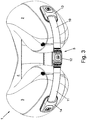
Figure 2 is a bottom plan view of the pillow ofFigure 1 ; -
Figure 3 is a front elevation view of the pillow ofFigure 1 ; -
Figure 4 is an oblique view of the front and side of the pillow ofFigure 1 ; -
Figure 5 is fragmentary oblique view of the rear and side of the pillow ofFigure 1 ; -
Figure 6 is an isometric view of the pillow ofFigure 1 ; -
Figure 7 is a fragmentary isometric view of a gate, elastic member and connecting means of the pillow ofFigure 1 ; -
Figure 8 is a fragmentary elevation view of a gate and connecting means of the pillow ofFigure 1 ; -
Figure 9 is an isometric view of the rear and side of the pillow ofFigure 1 ; -
Figure 10 is a rear elevation view of the pillow ofFigure 1 . - Referring to
Figure 1 , according to a preferred embodiment of the invention, apillow 1 comprises twowings bridging section 4 connecting thewings wings bridging section 4 form a substantially U-shaped shape. Thepillow 1 also comprises a first elastic member, which is not shown inFigure 1 . In the preferred embodiment, the whole of the first elastic member is at all times provided within thewing 2 and thebridging section 4. Thepillow 1 further comprises connectingmeans 5 which connect one portion of the first elastic member to a first fixing point FP1 on thebridging section 4 and another portion of the first elastic member to a second fixing point FP2 on thebridging section 4, so that the connectingmeans 5 can pass fromwing 2 towing 3 and the first elastic member can urge the wings towards one another. - In the figures, the
wings bridging section 4 by line L. - In this embodiment the pillow is shown ready for use in that the connecting
means 5 is shown already connecting one portion of the first elastic member to the first fixing point FP1 and another portion of the first elastic member to the second fixing point FP2. - In the present embodiment, the first elastic member is provided adjacent the first fixing point FP1.
- The connecting means 5 comprises a
first strap 10, abuckle 12, asecond strap 11 and a second elastic member. The second elastic member is not shown inFigure 1 . In the preferred embodiment, the whole of the second elastic member is at all times provided within thewing 3 and thebridging section 4. - The first and
second straps second straps - In the present embodiment, the first elastic member and second elastic member are provided within respective polyester sleeves. One sleeve is provided on the outside of the
wing 2 andbridging section 4, and the other sleeve is provided on the outside of thewing 3 andbridging section 4. The sleeves allow the elastic members to slide easily within them. - In the present embodiment, the first and second elastic members are respective straps.
- The connecting means 5 further comprises stitching which connects one end of the first elastic member to the
bridging section 4 at the first fixing point FP1, and stitching which connects one end of the second elastic member to thebridging section 4 at the second fixing point FP2. - The other end of the first elastic member is fixed to one end of the
first strap 10. The other end of thefirst strap 10 is fixed to one end of thebuckle 12. The other end of thebuckle 12 is fixed to one end of thesecond strap 11. The other end of thesecond strap 11 is fixed to one end of the second elastic member, which is the end that is not connected to the second fixing point FP2 by stitching. - The
buckle 12 has two parts, namely a male part and a female part. The male part is fixed to thefirst strap 10 and the female part is fixed tosecond strap 11. - In
Fig. 1 the pillow is shown in the "in use" position, that is to say the position it would take when being used and when wrapped around the neck of the user. The user's neck prevents the tips of thewings buckle 12 is snap-fitted into the female part to fasten the respective ends of thestraps wings pillow 1 is not wrapped around the user's neck but thebuckle 12 is fastened, the tips of thewings -
Gates wings gates second straps gates - As shown in
Fig. 1 , which is a plan view, the substantially U-shaped shape is formed in plan view. Thebridging section 4 has an outer peripheral surface, which is outer with respect to the centre of the substantially U-shaped shape in plan view. Thebridging section 4 also has an inner peripheral surface, which is inner with respect to the centre of the substantially U-shaped shape in plan view. - A rigid reinforcing and gripping member in the form of a
plate 6 is provided on, along and fixed to the outer peripheral surface of thebridging section 4. Theplate 6 is rigid, which is to say the resistance to bending of theplate 6 in a direction that moves thewings bridging section 4. Theplate 6 is fixed to thebridging section 4 at the first and second fixing points FP1 and FP2. The stitching that connects the first and second elastic members to the first and second fixing points FP1 and FP2 also fixes theplate 6 to the first and second fixing points FP1 and FP2. The fixing points FP1 and FP2 are opposite to portions of thebridging section 4 to whichwings - The deflection of the
wings pillow 1 of the present embodiment was measured to determine the effect of theplate 6. In particular, with only one end of theplate 6 held and thewings plate 6 was found to deflect by about 4cm due to self-weight of thepillow 1. In contrast, when the memory foam filling of thepillow 1 was removed, the corresponding deflection was found to be about 12cm due to self-weight of the filling. - The
plate 6 performs several functions: firstly, theplate 6 provides grip between the bridgingsection 6 and a surface which thebridging section 6 contacts; secondly, theplate 6 limits deformation of the bridging section; and thirdly, theplate 6 provides stable fixing points to which the first and second elastic members can be connected. Theplate 6 is formed of an elastomeric material, namely a thermoplastic elastomer (TPE). A suitable TPE material can be obtained from AIFFU International Limited of Wan Chai, Hong Kong. The coefficient of friction between theplate 6 and photocopier paper is about 0.7. - The
plate 6 in the present embodiment is about 205mm long at it longest point, 40mm wide, and 8mm thick at its thickest point. - The surface of the
wings bridging section 4 comprises a layer of flexible fabric forming a jacket. Thewings bridging section 4 are filled with a single piece of memory foam. Stable fixing points are necessary so that the elastic members urge the wings towards one another. Without theplate 6, the elastic members would be fixed only to the flexible fabric jacket, which alone would not provide stable fixing points. - In the position shown in
Fig. 1 , the first and second elastic members and a portion of each of first andsecond straps wings bridging section 4. The two layers of fabric provide respective slots in which the elastic members and the first andsecond straps - Referring to
Fig. 1 , the thickness of the thinnest portion of thebridging section 4, which is at its midpoint, is less than the thickness of the thickest portion of thewings wings wings - The
wings bridging section 4 are symmetrical in plan view about a line passing between the tips ofwings bridging section 4. Theplate 6 is symmetrical in plan view about the same line, as are the fixing points FP1, FP2. In the present embodiment, theplate 6 and the fixing points FP1, FP2 are on the rear surface of thebridging section 4. The rear surface faces in a rear direction, away from the tips of thewings - As shown in
Fig. 3 , the top surface of thebridging section 4 forms a V-shape in elevation view. -
Fig. 5 shows the detail of one end of the firstelastic member 7 through the fabric jacket and the detail of one end of theplate 6. One end of the firstelastic member 7 is connected to one end of theplate 6 at the first fixing point FP1 on the outer peripheral surface of thebridging section 4. Strong stitching connects the firstelastic member 7 and theplate 6 at the first fixing point FP1. One end of the secondelastic member 8 is connected to the other end ofplate 6 at the second fixing point FP2 in a corresponding manner. - In the present embodiment, the dimensions of each of the first and second
elastic members elastic member elastic member 7 is about 130mm, and so this is the length that can stretch. In the present embodiment, the elastic member is made from polyester woven elastic. A suitable polyester woven elastic material can be obtained from Tianao Holdings Limited of Kowloon, Hong Kong. In the present embodiment, the polyester woven elastic is 75% polyester and 25% rubber. -
Fig. 6 shows the other end of the firstelastic member 7 which is fixed to one end of thestrap 10. When the pillow is in the in use position, the firstelastic member 7 passes from thebridging section 4 to thewing 2. The elastic member passes along the outer peripheral surface of the bridging section from the first fixing point FP1 to the outer peripheral side surface of thewing 2 to the position where it is fixed to thestrap 10. From this point thestrap 10 passes along the outer peripheral side surface of thewing 2 to the outer peripheral tip surface of thewing 2. Thestrap 10 then leaves the surface of thewing 2 and passes towards thewing 3 until it reaches thebuckle 10. The secondelastic member 8 and thestrap 11 are provided on thebridging section 4 andwing 3 in a corresponding manner. - Once the
buckle 12 has been unfastened and the tension in the firstelastic member 7 has moved theelastic member 7 to the unstretched position, the whole of theelastic member 7 is provided within thebridging section 4. However, depending on the length of theelastic member 7, the whole of theelastic member 7 may be provided within both thebridging section 4 andwing 2 in the unstretched position. In the stretched position, however, the whole of theelastic member 7 is provided within both thebridging section 4 andwing 2. The same is true for the secondelastic member 8, mutatis mutandis. Referring toFigs. 1 to 8 ,gates means 5, in the present embodiment the male and female parts of thebuckle 12, respectively. - As shown in
Figs. 7 and 8 for thegate 14, thestrap 11 is retracted by the secondelastic member 8 and the female part ofbuckle 12 is caught ingate 14 once the whole ofstrap 11 has been retracted. The male part ofbuckle 12 is caught ingate 13 in a corresponding manner.Fig. 7 shows the two different positions of the female part ofbuckle 12.Fig. 8 shows different stages as thestrap 11 is retracted, and shows the different positions of the female part ofbuckle 12. In the top three stages, the arrow shows the direction of retraction. - Once the whole of each first and
second strap wings buckle 12 can be grasped and pulled by the user to pull thestraps wings elastic members - When the male and female parts of the
buckle 12 are caught in thegates elastic members buckle 12 towards thegates elastic member means 5 that has already been retracted remains fully retracted. - The
gates means 5 when the whole of each of the first andsecond straps wings straps wings elastic member 7 and thefirst strap 10, and at the join between the secondelastic member 8 and thesecond strap 11. Thus thegates wings -
Figs. 9 and10 show plate 6 on the rear surface of thebridging section 4. The rear surface faces in a rear direction, away from the tips of thewings plate 6 contacts the rear surface of thebridging section 4. This surface of theplate 6 is fixed around its periphery to the rear surface of thebridging section 4 by stitching. - When the pillow is in the in use position but not wrapped around the neck of a user, the surface of the
plate 6 fixed to the rear surface of thebridging section 4 is substantially planar. When the pillow is not in the in use position and thestraps plate 6 fixed to the rear surface of thebridging section 4 has a slightly bowed shape with the ends of the surface more rearward than the midpoint of the surface. - The
plate 6 has a peripheral ridge on its rear surface (that is the outer peripheral surface of theplate 6, which is the surface opposite to the surface fixed to the bridging section 4). The peripheral ridge is provided around the periphery of the rear surface of theplate 6. The peripheral ridge comprises two straight long ridges running in a direction fromwing 2 towing 3, and two short curved ridges joining the two straight ridges at their ends. The peripheral ridge is about 2mm high. - The
plate 6 is elongate with its longer dimension running in a direction fromwing 2 towing 3.Plate 6 comprises rubber and is substantially inextensible.Plate 6 is also resilient which means that when thepillow 1 is deformed for example by moving thewings plate 6 tends to return thewings - As can be seen most clearly from
Figs. 3 ,4 and10 , thepillow 1 is not symmetrical about a "horizontal" plane, i.e. a plane that is normal to the direction of view inFig. 1 . For example, as shown inFig. 4 , thewings bridging section 4 to the wing tip. In addition, as shown inFig. 10 , the top of thebridging section 4 curves downwards in the middle, but the bottom of thebridging section 4 is flat. This shaping makes the pillow more comfortable for the user as it fits the body more snuggly. - The preferred embodiment of the present invention has been described purely by way of example, and various modifications, additions and/or omissions will present themselves to one skilled in the art, all of which form part of the invention defined in the appended claims.
Claims (12)
- A pillow (1) comprising:two wings (2, 3);a bridging section (4) connecting the wings (2, 3) so that the wings (2, 3) and bridging section (4) form a substantially U-shaped shape;an elastic member (7); andconnecting means (5) for connecting one portion of the elastic member (7) to a fixing point (FP1) on a wing (2, 3) or the bridging section (4) and another portion of the elastic member (7) to a fixing point (FP2) on a wing (2, 3) or the bridging section (4), so that the elastic member (7), or the connecting means (5), or both, can pass from one wing (2, 3) to the other (3, 2) and the elastic member (7) can urge the wings (2, 3) towards one another,wherein, when the portions of the elastic member (7) are connected to a wing (2, 3) or the bridging section (4) by the connecting means (5), at least a part of the elastic member (7) is provided within a wing (2, 3) or the bridging section (4) or both so that the elastic member (7) can slidably retract into a wing (2, 3) or the bridging section (4) or both.
- A pillow (1) according to claim 1, wherein the elastic member (7) or the connecting means (5) comprises a strap (10, 11).
- A pillow (1) according to claim 2, wherein, when the portions of the elastic member (7) are connected to a wing (2, 3) or the bridging section (4) by the connecting means (5), at least a part of the strap (10, 11) of the elastic member (7) or connecting means (5) is provided within a wing (2, 3) or the bridging section (4) or both.
- A pillow (1) according to claim 2 or 3, wherein the strap (10, 11) of the connecting means (5) comprises at least two parts which can be disconnected from one another.
- A pillow (1) according to any preceding claim, wherein the elastic member (7) is provided adjacent to a fixing point (FP1, FP2).
- A pillow (1) according to any preceding claim, wherein the connecting means (5) comprises an additional elastic member (8).
- A pillow (1) according to any preceding claim, wherein the fixing points (FP1, FP2) are at different points on a wing (2, 3) or the bridging section (4), and the pillow (1) comprises a reinforcing member (6) that is fixed to a wing (2, 3) or the bridging section (4) at the fixing points (FP1, FP2).
- A pillow (1) according to claim 7, wherein the fixing points (FP1, FP2) are both on the bridging section (4), and preferably wherein the substantially U-shaped shape is formed in plan view, and the bridging section (4) has an outer peripheral surface in plan view, and the reinforcing member (6) is provided on the outer peripheral surface of the bridging section (4).
- A pillow (1) according to any preceding claim, comprising a stop for limiting movement of the elastic member (7) or connecting means (5).
- A pillow (1) according to claim 9, wherein the stop comprises a gate (13, 14) adapted to catch a holding portion of the connecting means (5) or elastic member (7).
- A pillow (1) according to claim 10, wherein the connecting means (5) or elastic member (7) comprises a strap (10, 11), and the holding portion is at one end of the strap (10, 11).
- A pillow (1) according to claim 10 or 11, wherein, when the holding portion is caught in the gate (13, 14) thereby limiting movement of the elastic member (7) or connecting means (5) due to urging by the elastic member (7), the elastic member (7) continues to urge the holding portion towards the gate (13, 14).
Applications Claiming Priority (2)
| Application Number | Priority Date | Filing Date | Title |
|---|---|---|---|
| GB1514182.3A GB2541204B (en) | 2015-08-11 | 2015-08-11 | Pillow |
| US14/937,465 US10076190B2 (en) | 2015-08-11 | 2015-11-10 | Pillow |
Publications (3)
| Publication Number | Publication Date |
|---|---|
| EP3130256A2 EP3130256A2 (en) | 2017-02-15 |
| EP3130256A3 EP3130256A3 (en) | 2017-05-03 |
| EP3130256B1 true EP3130256B1 (en) | 2018-08-01 |
Family
ID=54200544
Family Applications (1)
| Application Number | Title | Priority Date | Filing Date |
|---|---|---|---|
| EP16183740.6A Active EP3130256B1 (en) | 2015-08-11 | 2016-08-11 | Pillow |
Country Status (5)
| Country | Link |
|---|---|
| US (1) | US10076190B2 (en) |
| EP (1) | EP3130256B1 (en) |
| CN (1) | CN106419366A (en) |
| AU (1) | AU2016213783B2 (en) |
| GB (2) | GB2541314B (en) |
Families Citing this family (33)
| Publication number | Priority date | Publication date | Assignee | Title |
|---|---|---|---|---|
| USD817031S1 (en) * | 2015-08-07 | 2018-05-08 | Dg International Holdings Limited | Pillow |
| CA2999783C (en) * | 2015-09-29 | 2024-01-02 | Cabeau, Inc. | Neck pillow with chin supports, multiple anchor points, and magnetic clip |
| USD982934S1 (en) * | 2016-11-22 | 2023-04-11 | Ali Ganjavian Afshar | Pillow |
| US20180289183A1 (en) * | 2017-04-05 | 2018-10-11 | Samsonite Ip Holdings S.A R.L. | Articulating neck pillow |
| CN209031722U (en) * | 2017-07-11 | 2019-06-28 | 卡布公司 | Travel pillows and pillowcases for travel pillows |
| US20190038053A1 (en) * | 2017-08-07 | 2019-02-07 | David E. Brantingham | Travel pillow and methods of use |
| USD886495S1 (en) * | 2017-08-17 | 2020-06-09 | Gear Atelier Limited | Neck pillow |
| USD875431S1 (en) * | 2017-08-25 | 2020-02-18 | Jingang YANG | Pillow |
| USD878808S1 (en) * | 2018-01-05 | 2020-03-24 | Dg International Holdings Limited | Pillow |
| US10863827B1 (en) * | 2018-01-24 | 2020-12-15 | Johanna Marowitz | Back support |
| WO2019161375A1 (en) * | 2018-02-16 | 2019-08-22 | Cabeau, Inc. | Head support device |
| USD873052S1 (en) * | 2018-07-30 | 2020-01-21 | Dg International Holdings Limited | Pillow |
| CN108991876A (en) * | 2018-08-31 | 2018-12-14 | 天津中健国康纳米科技股份有限公司 | A kind of U-shaped pillow |
| USD911067S1 (en) * | 2018-09-06 | 2021-02-23 | Dg International Holdings Limited | Pillow |
| USD872503S1 (en) * | 2018-09-06 | 2020-01-14 | Dg International Holdings Limited | Pillow |
| USD901941S1 (en) * | 2018-09-08 | 2020-11-17 | Dg International Holdings Limited | Pillow |
| WO2020095225A1 (en) * | 2018-11-07 | 2020-05-14 | Mura Claudio | Headrest device |
| USD899818S1 (en) * | 2019-01-28 | 2020-10-27 | Xiaohu Qu | Neck pillow |
| US11000139B1 (en) * | 2019-08-27 | 2021-05-11 | Alice Marianne R. Dutt | Neck pillow |
| USD899819S1 (en) * | 2019-09-05 | 2020-10-27 | Sutton Jesse | Travel pillow with a flat neck |
| USD961961S1 (en) * | 2019-09-06 | 2022-08-30 | Dg International Holdings Limited | Pillow |
| USD938758S1 (en) * | 2019-10-22 | 2021-12-21 | Anjadeer LLC | Car seat head and neck support for child |
| USD923361S1 (en) * | 2019-10-27 | 2021-06-29 | Upper Echelon Products Llc | Neck pillow |
| DE202019004477U1 (en) * | 2019-11-04 | 2021-02-09 | Travel Blue Limited | Travel pillow |
| US11723470B1 (en) * | 2020-04-17 | 2023-08-15 | Robert C. Farley | Head support apparatus and method |
| USD991703S1 (en) * | 2020-07-08 | 2023-07-11 | Easepal Enterprises Ltd. | Travel neck pillow |
| USD963258S1 (en) * | 2021-02-02 | 2022-09-06 | Andrea Hollis | Padded Elizabethan pet collar |
| JP2022161460A (en) * | 2021-04-09 | 2022-10-21 | 西川株式会社 | portable pillow |
| USD966744S1 (en) * | 2021-07-13 | 2022-10-18 | Fangyan Fu | U-shaped pillow |
| WO2024026526A1 (en) * | 2022-08-05 | 2024-02-08 | Slip IP Holdings Pty Ltd | A pillow |
| CR20250166A (en) * | 2022-11-04 | 2025-05-22 | Azurous Inc Dba Cabeau | HEAD STABILIZING TRAVEL PILLOW |
| USD1110068S1 (en) * | 2023-09-01 | 2026-01-27 | Huiming Zhu | Nursing pillow |
| US20250221553A1 (en) * | 2024-01-08 | 2025-07-10 | Yakov Perper | Shoulder Support for Lateral Decubitus Positioning |
Family Cites Families (32)
| Publication number | Priority date | Publication date | Assignee | Title |
|---|---|---|---|---|
| US4030781A (en) * | 1976-01-21 | 1977-06-21 | Howard Harold P | Headrest |
| US4114948A (en) * | 1977-08-03 | 1978-09-19 | Otis Perkey R V | Auto headrest |
| DE2856366A1 (en) * | 1978-08-17 | 1980-02-28 | Otis Perkey R V | Car seat head rest comprising back and side portions - is made of polyurethane foam in textile case and responds to pressure during driving |
| US4285081A (en) * | 1979-10-22 | 1981-08-25 | Price George W E | Device for recumbency of the head and neck |
| US4763369A (en) * | 1986-06-20 | 1988-08-16 | Donald Spector | Transformable pillow |
| JP2554480B2 (en) | 1986-11-07 | 1996-11-13 | 株式会社 ゼクセル | Time measuring device |
| US4738488A (en) | 1987-04-20 | 1988-04-19 | Camelio Carol L | Adjustable headrest |
| US5154477A (en) * | 1991-04-09 | 1992-10-13 | Jim Lacy | Head support for vehicle seat backs |
| US5330255A (en) | 1992-11-12 | 1994-07-19 | Davidson Textron Inc. | Seat integrated inflatable neck support |
| IT1284834B1 (en) * | 1996-09-30 | 1998-05-22 | Camau System Di Casale & C S N | DEVICE TO ADAPT AND FIX A HELMET TO THE USER'S HEAD. |
| US6010192A (en) * | 1998-07-29 | 2000-01-04 | King; Jenny K. | Travel pillow |
| US6299248B1 (en) | 1999-10-22 | 2001-10-09 | Richard Gennaro | Posture system |
| US6957462B1 (en) | 2004-11-17 | 2005-10-25 | Wilcox Richard B | Pillow with slidable strap through it |
| TWM303135U (en) | 2006-05-19 | 2006-12-21 | Jian-Yi Jeng | Adjustable headrest |
| WO2009009091A1 (en) * | 2007-07-10 | 2009-01-15 | Lois Lopez | Head and neck protection device |
| CN101366561A (en) * | 2007-08-16 | 2009-02-18 | 曾亮维 | helmet |
| KR100987961B1 (en) * | 2007-11-08 | 2010-10-18 | 남해현 | Chair with headrest |
| US7883150B2 (en) | 2009-02-05 | 2011-02-08 | Grenier Laura D | Portable neck and head support with strap for holding during use and storage |
| KR101366838B1 (en) * | 2010-07-13 | 2014-02-27 | (주)에스엔텍 | In-line sputtering system |
| GB2483461B (en) * | 2010-09-08 | 2013-01-09 | Gina Eileen Hopcroft | A travel pillow |
| KR20120006946U (en) | 2011-03-30 | 2012-10-10 | (주) 제이큐티 | Neck pillow for travel of fix-choice type |
| CN202504861U (en) * | 2012-03-21 | 2012-10-31 | 黄甲平 | U-shaped neck pillow |
| US9635962B2 (en) | 2012-04-12 | 2017-05-02 | Cabeau, Inc. | Travel pillow with lateral and rear support bar and a flat and thin back |
| CN203088260U (en) * | 2013-02-06 | 2013-07-31 | 黄怡 | Chair with pillow |
| CN104367074A (en) * | 2013-08-16 | 2015-02-25 | 西安永成电子科技有限责任公司 | Heat insulation noon break pillow integrated with earplugs |
| US20150059098A1 (en) * | 2013-09-03 | 2015-03-05 | Hyoung Sook JUNG | Neck pillow having a strap |
| CN104687857B (en) * | 2013-12-05 | 2017-04-12 | 特力股份有限公司 | Multifunctional Support Cushion |
| CN203651708U (en) * | 2014-01-15 | 2014-06-18 | 桂林电子科技大学 | Safety belt of automobile |
| CN204105564U (en) * | 2014-03-04 | 2015-01-21 | 深圳市诺嘉智能养生发展有限公司 | A kind of U-shaped massage pillow |
| US9968197B2 (en) * | 2014-03-11 | 2018-05-15 | Cabeau, Inc. | Travel pillow |
| CN103989372A (en) * | 2014-05-19 | 2014-08-20 | 余欣 | U-shaped pillow |
| CN204015805U (en) * | 2014-08-15 | 2014-12-17 | 泉州德信织造有限公司 | A kind of disposable pillow with neck blanket |
-
2015
- 2015-08-11 GB GB1618860.9A patent/GB2541314B/en active Active
- 2015-08-11 GB GB1514182.3A patent/GB2541204B/en active Active
- 2015-11-10 US US14/937,465 patent/US10076190B2/en active Active
-
2016
- 2016-08-11 CN CN201610893609.5A patent/CN106419366A/en active Pending
- 2016-08-11 AU AU2016213783A patent/AU2016213783B2/en active Active
- 2016-08-11 EP EP16183740.6A patent/EP3130256B1/en active Active
Also Published As
| Publication number | Publication date |
|---|---|
| GB201514182D0 (en) | 2015-09-23 |
| EP3130256A3 (en) | 2017-05-03 |
| US20170042332A1 (en) | 2017-02-16 |
| AU2016213783B2 (en) | 2021-01-28 |
| GB2541314A (en) | 2017-02-15 |
| AU2016213783A1 (en) | 2017-03-02 |
| GB2541204B (en) | 2017-07-26 |
| US10076190B2 (en) | 2018-09-18 |
| EP3130256A2 (en) | 2017-02-15 |
| CN106419366A (en) | 2017-02-22 |
| GB2541204A (en) | 2017-02-15 |
| GB2541314B (en) | 2017-07-26 |
Similar Documents
| Publication | Publication Date | Title |
|---|---|---|
| AU2016213783B2 (en) | Pillow | |
| US9675509B2 (en) | Patient transfer assembly | |
| US20100115739A1 (en) | Clip with hard and soft grips | |
| US20150313396A1 (en) | Footwear Application Assisting Apparatus | |
| US8011375B2 (en) | Unitary hair clip and method of use | |
| US5007415A (en) | Joint brace | |
| US11412711B2 (en) | Pet leash having a loop handle and sliding cinch member to adjust loop size of loop handle | |
| CN101193575A (en) | Seat structure and saddle retraction method | |
| US20090247377A1 (en) | Penis exercise machine | |
| HK1228701A (en) | Pillow | |
| HK1228701A1 (en) | Pillow | |
| HK1228702A (en) | Pillow | |
| HK1228702A1 (en) | Pillow | |
| CN116898199A (en) | Arm strap fastening assembly for wearable accessory arm straps | |
| KR200479899Y1 (en) | Band for protecting waist combined with cushion member | |
| JP6510725B1 (en) | Finger pinch prevention device | |
| KR200448125Y1 (en) | Telescopic belt | |
| KR102119998B1 (en) | The band apparatus for carrying baby | |
| JP6045294B2 (en) | Wig stopper and wig | |
| CN113116027A (en) | Pulling-on piece | |
| WO2020241173A1 (en) | Seat | |
| KR20170061568A (en) | A frame assembly and a motion assist apparatus comprising thereof | |
| US9144468B2 (en) | Fastening element for a penis | |
| KR101455295B1 (en) | Pressure flexibility type waist protector | |
| CN209921253U (en) | Safety belt protective sleeve |
Legal Events
| Date | Code | Title | Description |
|---|---|---|---|
| PUAI | Public reference made under article 153(3) epc to a published international application that has entered the european phase |
Free format text: ORIGINAL CODE: 0009012 |
|
| AK | Designated contracting states |
Kind code of ref document: A2 Designated state(s): AL AT BE BG CH CY CZ DE DK EE ES FI FR GB GR HR HU IE IS IT LI LT LU LV MC MK MT NL NO PL PT RO RS SE SI SK SM TR |
|
| AX | Request for extension of the european patent |
Extension state: BA ME |
|
| PUAL | Search report despatched |
Free format text: ORIGINAL CODE: 0009013 |
|
| AK | Designated contracting states |
Kind code of ref document: A3 Designated state(s): AL AT BE BG CH CY CZ DE DK EE ES FI FR GB GR HR HU IE IS IT LI LT LU LV MC MK MT NL NO PL PT RO RS SE SI SK SM TR |
|
| AX | Request for extension of the european patent |
Extension state: BA ME |
|
| RIC1 | Information provided on ipc code assigned before grant |
Ipc: A47C 7/38 20060101AFI20170330BHEP |
|
| 17P | Request for examination filed |
Effective date: 20170713 |
|
| RBV | Designated contracting states (corrected) |
Designated state(s): AL AT BE BG CH CY CZ DE DK EE ES FI FR GB GR HR HU IE IS IT LI LT LU LV MC MK MT NL NO PL PT RO RS SE SI SK SM TR |
|
| GRAP | Despatch of communication of intention to grant a patent |
Free format text: ORIGINAL CODE: EPIDOSNIGR1 |
|
| INTG | Intention to grant announced |
Effective date: 20180215 |
|
| GRAS | Grant fee paid |
Free format text: ORIGINAL CODE: EPIDOSNIGR3 |
|
| GRAA | (expected) grant |
Free format text: ORIGINAL CODE: 0009210 |
|
| RBV | Designated contracting states (corrected) |
Designated state(s): AL AT BE BG CH CY CZ DE DK EE ES FI FR GR HR HU IE IS IT LI LT LU LV MC MK MT NL NO PL PT RO RS SE SI SK SM TR |
|
| AK | Designated contracting states |
Kind code of ref document: B1 Designated state(s): AL AT BE BG CH CY CZ DE DK EE ES FI FR GR HR HU IE IS IT LI LT LU LV MC MK MT NL NO PL PT RO RS SE SI SK SM TR |
|
| REG | Reference to a national code |
Ref country code: CH Ref legal event code: EP Ref country code: AT Ref legal event code: REF Ref document number: 1023297 Country of ref document: AT Kind code of ref document: T Effective date: 20180815 |
|
| REG | Reference to a national code |
Ref country code: IE Ref legal event code: FG4D |
|
| REG | Reference to a national code |
Ref country code: DE Ref legal event code: R096 Ref document number: 602016004473 Country of ref document: DE |
|
| REG | Reference to a national code |
Ref country code: CH Ref legal event code: NV Representative=s name: SERVOPATENT GMBH, CH |
|
| REG | Reference to a national code |
Ref country code: FR Ref legal event code: PLFP Year of fee payment: 3 |
|
| REG | Reference to a national code |
Ref country code: NL Ref legal event code: MP Effective date: 20180801 |
|
| REG | Reference to a national code |
Ref country code: LT Ref legal event code: MG4D |
|
| REG | Reference to a national code |
Ref country code: AT Ref legal event code: MK05 Ref document number: 1023297 Country of ref document: AT Kind code of ref document: T Effective date: 20180801 |
|
| PG25 | Lapsed in a contracting state [announced via postgrant information from national office to epo] |
Ref country code: FI Free format text: LAPSE BECAUSE OF FAILURE TO SUBMIT A TRANSLATION OF THE DESCRIPTION OR TO PAY THE FEE WITHIN THE PRESCRIBED TIME-LIMIT Effective date: 20180801 Ref country code: PL Free format text: LAPSE BECAUSE OF FAILURE TO SUBMIT A TRANSLATION OF THE DESCRIPTION OR TO PAY THE FEE WITHIN THE PRESCRIBED TIME-LIMIT Effective date: 20180801 Ref country code: LT Free format text: LAPSE BECAUSE OF FAILURE TO SUBMIT A TRANSLATION OF THE DESCRIPTION OR TO PAY THE FEE WITHIN THE PRESCRIBED TIME-LIMIT Effective date: 20180801 Ref country code: NO Free format text: LAPSE BECAUSE OF FAILURE TO SUBMIT A TRANSLATION OF THE DESCRIPTION OR TO PAY THE FEE WITHIN THE PRESCRIBED TIME-LIMIT Effective date: 20181101 Ref country code: GR Free format text: LAPSE BECAUSE OF FAILURE TO SUBMIT A TRANSLATION OF THE DESCRIPTION OR TO PAY THE FEE WITHIN THE PRESCRIBED TIME-LIMIT Effective date: 20181102 Ref country code: NL Free format text: LAPSE BECAUSE OF FAILURE TO SUBMIT A TRANSLATION OF THE DESCRIPTION OR TO PAY THE FEE WITHIN THE PRESCRIBED TIME-LIMIT Effective date: 20180801 Ref country code: SE Free format text: LAPSE BECAUSE OF FAILURE TO SUBMIT A TRANSLATION OF THE DESCRIPTION OR TO PAY THE FEE WITHIN THE PRESCRIBED TIME-LIMIT Effective date: 20180801 Ref country code: RS Free format text: LAPSE BECAUSE OF FAILURE TO SUBMIT A TRANSLATION OF THE DESCRIPTION OR TO PAY THE FEE WITHIN THE PRESCRIBED TIME-LIMIT Effective date: 20180801 Ref country code: AT Free format text: LAPSE BECAUSE OF FAILURE TO SUBMIT A TRANSLATION OF THE DESCRIPTION OR TO PAY THE FEE WITHIN THE PRESCRIBED TIME-LIMIT Effective date: 20180801 Ref country code: IS Free format text: LAPSE BECAUSE OF FAILURE TO SUBMIT A TRANSLATION OF THE DESCRIPTION OR TO PAY THE FEE WITHIN THE PRESCRIBED TIME-LIMIT Effective date: 20181201 |
|
| PG25 | Lapsed in a contracting state [announced via postgrant information from national office to epo] |
Ref country code: LV Free format text: LAPSE BECAUSE OF FAILURE TO SUBMIT A TRANSLATION OF THE DESCRIPTION OR TO PAY THE FEE WITHIN THE PRESCRIBED TIME-LIMIT Effective date: 20180801 Ref country code: HR Free format text: LAPSE BECAUSE OF FAILURE TO SUBMIT A TRANSLATION OF THE DESCRIPTION OR TO PAY THE FEE WITHIN THE PRESCRIBED TIME-LIMIT Effective date: 20180801 Ref country code: AL Free format text: LAPSE BECAUSE OF FAILURE TO SUBMIT A TRANSLATION OF THE DESCRIPTION OR TO PAY THE FEE WITHIN THE PRESCRIBED TIME-LIMIT Effective date: 20180801 |
|
| PG25 | Lapsed in a contracting state [announced via postgrant information from national office to epo] |
Ref country code: ES Free format text: LAPSE BECAUSE OF FAILURE TO SUBMIT A TRANSLATION OF THE DESCRIPTION OR TO PAY THE FEE WITHIN THE PRESCRIBED TIME-LIMIT Effective date: 20180801 Ref country code: MC Free format text: LAPSE BECAUSE OF FAILURE TO SUBMIT A TRANSLATION OF THE DESCRIPTION OR TO PAY THE FEE WITHIN THE PRESCRIBED TIME-LIMIT Effective date: 20180801 Ref country code: CZ Free format text: LAPSE BECAUSE OF FAILURE TO SUBMIT A TRANSLATION OF THE DESCRIPTION OR TO PAY THE FEE WITHIN THE PRESCRIBED TIME-LIMIT Effective date: 20180801 Ref country code: IT Free format text: LAPSE BECAUSE OF FAILURE TO SUBMIT A TRANSLATION OF THE DESCRIPTION OR TO PAY THE FEE WITHIN THE PRESCRIBED TIME-LIMIT Effective date: 20180801 Ref country code: EE Free format text: LAPSE BECAUSE OF FAILURE TO SUBMIT A TRANSLATION OF THE DESCRIPTION OR TO PAY THE FEE WITHIN THE PRESCRIBED TIME-LIMIT Effective date: 20180801 Ref country code: RO Free format text: LAPSE BECAUSE OF FAILURE TO SUBMIT A TRANSLATION OF THE DESCRIPTION OR TO PAY THE FEE WITHIN THE PRESCRIBED TIME-LIMIT Effective date: 20180801 Ref country code: LU Free format text: LAPSE BECAUSE OF NON-PAYMENT OF DUE FEES Effective date: 20180811 |
|
| REG | Reference to a national code |
Ref country code: DE Ref legal event code: R097 Ref document number: 602016004473 Country of ref document: DE |
|
| REG | Reference to a national code |
Ref country code: BE Ref legal event code: MM Effective date: 20180831 |
|
| REG | Reference to a national code |
Ref country code: IE Ref legal event code: MM4A |
|
| PG25 | Lapsed in a contracting state [announced via postgrant information from national office to epo] |
Ref country code: DK Free format text: LAPSE BECAUSE OF FAILURE TO SUBMIT A TRANSLATION OF THE DESCRIPTION OR TO PAY THE FEE WITHIN THE PRESCRIBED TIME-LIMIT Effective date: 20180801 Ref country code: SK Free format text: LAPSE BECAUSE OF FAILURE TO SUBMIT A TRANSLATION OF THE DESCRIPTION OR TO PAY THE FEE WITHIN THE PRESCRIBED TIME-LIMIT Effective date: 20180801 Ref country code: SM Free format text: LAPSE BECAUSE OF FAILURE TO SUBMIT A TRANSLATION OF THE DESCRIPTION OR TO PAY THE FEE WITHIN THE PRESCRIBED TIME-LIMIT Effective date: 20180801 |
|
| PLBE | No opposition filed within time limit |
Free format text: ORIGINAL CODE: 0009261 |
|
| STAA | Information on the status of an ep patent application or granted ep patent |
Free format text: STATUS: NO OPPOSITION FILED WITHIN TIME LIMIT |
|
| 26N | No opposition filed |
Effective date: 20190503 |
|
| PG25 | Lapsed in a contracting state [announced via postgrant information from national office to epo] |
Ref country code: IE Free format text: LAPSE BECAUSE OF NON-PAYMENT OF DUE FEES Effective date: 20180811 |
|
| PG25 | Lapsed in a contracting state [announced via postgrant information from national office to epo] |
Ref country code: SI Free format text: LAPSE BECAUSE OF FAILURE TO SUBMIT A TRANSLATION OF THE DESCRIPTION OR TO PAY THE FEE WITHIN THE PRESCRIBED TIME-LIMIT Effective date: 20180801 Ref country code: BE Free format text: LAPSE BECAUSE OF NON-PAYMENT OF DUE FEES Effective date: 20180831 |
|
| PG25 | Lapsed in a contracting state [announced via postgrant information from national office to epo] |
Ref country code: MT Free format text: LAPSE BECAUSE OF NON-PAYMENT OF DUE FEES Effective date: 20180811 |
|
| PG25 | Lapsed in a contracting state [announced via postgrant information from national office to epo] |
Ref country code: TR Free format text: LAPSE BECAUSE OF FAILURE TO SUBMIT A TRANSLATION OF THE DESCRIPTION OR TO PAY THE FEE WITHIN THE PRESCRIBED TIME-LIMIT Effective date: 20180801 |
|
| PG25 | Lapsed in a contracting state [announced via postgrant information from national office to epo] |
Ref country code: PT Free format text: LAPSE BECAUSE OF FAILURE TO SUBMIT A TRANSLATION OF THE DESCRIPTION OR TO PAY THE FEE WITHIN THE PRESCRIBED TIME-LIMIT Effective date: 20180801 |
|
| REG | Reference to a national code |
Ref country code: CH Ref legal event code: PCAR Free format text: NEW ADDRESS: WANNERSTRASSE 9/1, 8045 ZUERICH (CH) |
|
| PG25 | Lapsed in a contracting state [announced via postgrant information from national office to epo] |
Ref country code: HU Free format text: LAPSE BECAUSE OF FAILURE TO SUBMIT A TRANSLATION OF THE DESCRIPTION OR TO PAY THE FEE WITHIN THE PRESCRIBED TIME-LIMIT; INVALID AB INITIO Effective date: 20160811 Ref country code: MK Free format text: LAPSE BECAUSE OF NON-PAYMENT OF DUE FEES Effective date: 20180801 Ref country code: CY Free format text: LAPSE BECAUSE OF FAILURE TO SUBMIT A TRANSLATION OF THE DESCRIPTION OR TO PAY THE FEE WITHIN THE PRESCRIBED TIME-LIMIT Effective date: 20180801 |
|
| PGFP | Annual fee paid to national office [announced via postgrant information from national office to epo] |
Ref country code: FR Payment date: 20250521 Year of fee payment: 10 |
|
| PGFP | Annual fee paid to national office [announced via postgrant information from national office to epo] |
Ref country code: DE Payment date: 20250620 Year of fee payment: 10 |
|
| PGFP | Annual fee paid to national office [announced via postgrant information from national office to epo] |
Ref country code: BG Payment date: 20250818 Year of fee payment: 10 |
|
| PGFP | Annual fee paid to national office [announced via postgrant information from national office to epo] |
Ref country code: CH Payment date: 20250922 Year of fee payment: 10 |