EP3130100B1 - Verfahren für ein redundantes übertragungssystem mit prp und fehlvorhersage - Google Patents
Verfahren für ein redundantes übertragungssystem mit prp und fehlvorhersage Download PDFInfo
- Publication number
- EP3130100B1 EP3130100B1 EP15718810.3A EP15718810A EP3130100B1 EP 3130100 B1 EP3130100 B1 EP 3130100B1 EP 15718810 A EP15718810 A EP 15718810A EP 3130100 B1 EP3130100 B1 EP 3130100B1
- Authority
- EP
- European Patent Office
- Prior art keywords
- data
- transmission
- transmitted
- network
- transmission system
- Prior art date
- Legal status (The legal status is an assumption and is not a legal conclusion. Google has not performed a legal analysis and makes no representation as to the accuracy of the status listed.)
- Active
Links
Images
Classifications
-
- H—ELECTRICITY
- H04—ELECTRIC COMMUNICATION TECHNIQUE
- H04L—TRANSMISSION OF DIGITAL INFORMATION, e.g. TELEGRAPHIC COMMUNICATION
- H04L1/00—Arrangements for detecting or preventing errors in the information received
- H04L1/22—Arrangements for detecting or preventing errors in the information received using redundant apparatus to increase reliability
-
- H—ELECTRICITY
- H04—ELECTRIC COMMUNICATION TECHNIQUE
- H04L—TRANSMISSION OF DIGITAL INFORMATION, e.g. TELEGRAPHIC COMMUNICATION
- H04L1/00—Arrangements for detecting or preventing errors in the information received
- H04L1/004—Arrangements for detecting or preventing errors in the information received by using forward error control
-
- H—ELECTRICITY
- H04—ELECTRIC COMMUNICATION TECHNIQUE
- H04L—TRANSMISSION OF DIGITAL INFORMATION, e.g. TELEGRAPHIC COMMUNICATION
- H04L1/00—Arrangements for detecting or preventing errors in the information received
- H04L1/004—Arrangements for detecting or preventing errors in the information received by using forward error control
- H04L1/0041—Arrangements at the transmitter end
-
- H—ELECTRICITY
- H04—ELECTRIC COMMUNICATION TECHNIQUE
- H04L—TRANSMISSION OF DIGITAL INFORMATION, e.g. TELEGRAPHIC COMMUNICATION
- H04L1/00—Arrangements for detecting or preventing errors in the information received
- H04L1/08—Arrangements for detecting or preventing errors in the information received by repeating transmission, e.g. Verdan system
-
- H—ELECTRICITY
- H04—ELECTRIC COMMUNICATION TECHNIQUE
- H04L—TRANSMISSION OF DIGITAL INFORMATION, e.g. TELEGRAPHIC COMMUNICATION
- H04L45/00—Routing or path finding of packets in data switching networks
- H04L45/28—Routing or path finding of packets in data switching networks using route fault recovery
-
- H—ELECTRICITY
- H04—ELECTRIC COMMUNICATION TECHNIQUE
- H04L—TRANSMISSION OF DIGITAL INFORMATION, e.g. TELEGRAPHIC COMMUNICATION
- H04L1/00—Arrangements for detecting or preventing errors in the information received
- H04L2001/0092—Error control systems characterised by the topology of the transmission link
- H04L2001/0096—Channel splitting in point-to-point links
Definitions
- the invention relates to a method for operating a transmission system that has a first network and at least one further network, data being exchanged between these at least two networks in that data from the first network are supplied to duplicating means, the supplied data wirelessly over at least two transmission paths transmitted by means of PRP to separating means and forwarded by the separating means to the connected further network, according to the features of claim 1.
- Existing transmission systems were in WO2011 / 160957 on December 29, 2011 and in US2010 / 110904 on May 6, 2010 disclosed.
- Such known transmission systems are used in safety-critical cases in process engineering systems, stationary or mobile work equipment, for example in work vehicles such as cranes or the like.
- such a transmission system works satisfactorily because there is redundancy of the two transmission links. For example, if a wireless transmission link is disturbed or fails, the at least second transmission link can be used to ensure data transmission from the first to the further network.
- the redundancy mechanism would be permanently active and the data would only be transmitted over the only transmission link still available, whereas the at least further transmission link is no longer available, which, however, is not or not readily apparent to a user of the transmission system. It follows from this that there is no longer any redundancy reserve available because the actual redundancy mechanism, namely the separate transmission of data from one network to the other, is permanently disrupted.
- the invention is therefore based on the object of improving a method for operating a transmission system with regard to its safety reserves.
- the data are transmitted as data packets and it is determined whether a data packet has been transmitted or not and, based on this, it is derived whether the transmission system is working error-free or not.
- it can thus be determined whether the redundancy mechanism is working or not and, based on this, a Statement can be derived as to whether the transmission system is error-free or faulty, that is, works using the redundancy mechanism. This creates the possibility for the user to monitor the transmission system and possibly initiate countermeasures. If, for example, it is determined that all data packets have been transmitted error-free both over one and the other transmission path, it can be deduced from this that the entire transmission system is working without errors and the required and desired redundancy reserve is available without restriction.
- each error-free transmitted data packet is counted and related to the total number of transmitted data packets, and a failure probability is calculated from this.
- the redundancy box knows how large the number of data packets is that are sent on a transmission path. This number can be transmitted to the separating means (redundancy box), this separating means counting the data packets which have been transmitted error-free on this transmission link and are received by them. These two numbers are set in relation, whereby in the case of error-free transmission the subscription ratio is equal to 1. However, if it is less than 1, it can be assumed that data packets were lost during transmission on the transmission path as a result of malfunctions, failures or the like. A decision can then be made as to the extent to which the ratio is less than 1.
- the redundancy reserve (which is, for example, a ratio of 0.9 or 0.8) is not yet undershot, so that intervention by a user of the transmission system is not yet necessary. Only when this redundancy reserve is further undershot, for example 0.9 or 0.8, is the user required to intervene with regard to an error analysis or error correction after the error analysis has taken place, although the reliable data transmission between the first and the further network still takes place. In such a case, a failure of the transmission system or an impairment can be counteracted despite further correct data transmission. This is of particular advantage from a safety-critical point of view, since, according to the invention, errors can be recognized in advance and acted accordingly.
- the procedure described above takes place separately from one another for each transmission link.
- This failure probability or the redundancy reserve is displayed in a particularly advantageous manner.
- Appropriate means are provided for this. These means can, for example, be a kind of traffic light that signals whether the transmission system is working 100% error-free, including all units of the transmission system, without the redundancy mechanism having used. With the appropriate light sources, this status could be displayed in green, for example.
- redundancy reserve is no longer equal to 1 but less than 1
- this can be indicated by light sources, for example in yellow. This takes place as long as the redundancy reserve is less than 1, but above a predefinable threshold that is less than 1 and greater than 0.
- This threshold can be, for example, at the pre-recorded value 0.9 or 0.8 or values deviating therefrom.
- this color indicates to the operator of the transmission system that the redundancy mechanism has started and the data transmission is still going on error-free, but limited in terms of redundancy. From this he can deduce whether he wants to carry out an error analysis and, depending on this, eliminate the errors found.
- Detected errors can be, for example, disturbances in the transmission path or hardware errors in components of the transmission system. Only when the probability of failure exceeds a predefinable threshold, which is equivalent to falling below the redundancy reserve below a threshold value less than 1, there is a significant restriction not only in data transmission but also in redundancy, so that safety-critical states can arise if this state is maintained . It is therefore necessary to act in such a case, which can be signaled by red light sources, in order to avoid such safety-critical conditions.
- a notification is triggered if the probability of failure exceeds a predefinable threshold or the redundancy reserve falls below a predefinable value less than 1.
- This can be, for example, an SMS message or a comparable message, an e-mail, or the like, which a network administrator receives, for example.
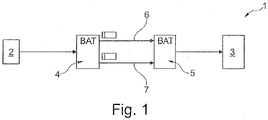
- the method presented can be applied to a transmission system that is included in the Figure 1 is shown.
- Figure 1 shows a basic arrangement of a transmission system which has two networks 2, 3 which are intended to exchange data with one another. This data exchange can take place either unidirectionally from network 2 to network 3 (or vice versa), but also bidirectionally between the two networks 2, 3.
- the networks 2, 3 can be simple or complex networks, for example in a ring or line topology or the like. However, it is also conceivable that such a network 2, 3 comprises only a single element such as, for example, a sensor, an actuator, a control device or the like.
- duplication means 4 are present. These doubling means 4 divide the supplied data stream into two data streams. The merging of the two data streams also takes place after they have been received via separating means 5, the received data streams being forwarded to the network 3 after the merging.
- the transmission of the data between the doubling means and the separating means 5 takes place wirelessly by means of PRP via two similar or different transmission paths 6, 7.
- the wireless transmission takes place in an advantageous manner via radio, optical transmission also being conceivable.
- one transmission link 6 is a radio transmission link and the second transmission link 7 is an optical data transmission link.
- both transmission links 6, 7 are, for example, radio transmission links
- the data more precisely the data packets, can be transmitted over these two radio transmission links, for example at the same frequency or different frequencies and otherwise the same parameters or different transmission parameters from one another.
- Similar transmission links 6, 7 are to be preferred with regard to their structure, whereas transmission links 6, 7 that are different from one another (for example optical / radio or transmission parameters that differ from one another) are preferred with regard to increasing the redundancy.
- each data packet is transmitted several times over the same transmission path 6, 7 and / or an error correction value is assigned to each data packet.
- the data packets are then transmitted in a corresponding manner via the transmission links 6, 7, with the data packets being appropriately evaluated by the separating means 5 (in the case of PRP also referred to as a redundancy box), processed if necessary and fed to the further network 3 as data packets.
- the above description of the Figure 1 relates to a unidirectional data transmission from the first network 2 to the further, in particular the second network 3.
- the doubling means 4 are designed to split the data stream and the separating means 5 are designed to merge the received data stream.
- further doubling means 4 or separating means 5 can be present in the transmission path between network 3 and network 2, so that a double structure results.
- the means 4, 5 can also be designed not only to double the supplied data stream, but also to separate the data streams supplied via the transmission links 6, 7, which also applies to the separating means 5.
Landscapes
- Engineering & Computer Science (AREA)
- Computer Networks & Wireless Communication (AREA)
- Signal Processing (AREA)
- Detection And Prevention Of Errors In Transmission (AREA)
- Data Exchanges In Wide-Area Networks (AREA)
- Mobile Radio Communication Systems (AREA)
- Small-Scale Networks (AREA)
Description
- Die Erfindung betrifft ein Verfahren zum Betreiben eines Übertragungssystems, das ein erstes Netzwerk und zumindest ein weiteres Netzwerk aufweist, wobei zwischen diesen zumindest zwei Netzwerken dadurch Daten ausgetauscht werden, dass Daten des ersten Netzwerkes Verdopplungsmitteln zugeführt werden, wobei die zugeführten Daten über zumindest zwei Übertragungsstrecken drahtlos mittels PRP zu Separiermitteln übertragen und von den Separiermitteln an das angeschlossene weitere Netzwerk weitergeleitet werden, gemäß den Merkmalen des Patentanspruches 1. Bestehende Übertragungssysteme wurden in
WO2011/160957 am 29.12.2011 und inUS2010/110904 am 06.05.2010 offenbart. - Solche bekannten Übertragungssysteme finden Anwendung in sicherheitskritischen Fällen bei verfahrenstechnischen Anlagen, stationären oder mobilen Arbeitseinrichtungen, beispielsweise bei Arbeitsfahrzeugen wie Krane oder dergleichen.
- Es ist dabei wichtig, dass Daten zuverlässig von dem ersten Netzwerk zu dem zumindest weiteren Netzwerk übertragen werden. Eine solche sicherheitskritische Datenübertragung ist besonders dann wichtig, wenn die Daten über eine drahtlose Übertragungsstrecke übertragen werden. Hierzu hat es schon eine Verbesserung derart gegeben, dass nicht nur eine Übertragungsstrecke, sondern zumindest zwei, vorzugsweise genau zwei Übertragungsstrecken für diese Sicherheitsanwendung (auch Safety-Anwendung genannt) eingesetzt werden. Eine weitere Verbesserung dieser redundanten Datenübertragung hat dadurch stattgefunden, dass sie drahtlos, das heißt über Funk oder Licht, mittels des PRP (Parallel Redundancy Protocol), welches ein Layer-2-Redundanzverfahren ist, welches von höheren Schichten unabhängig ist und sich vor allen Dingen für Echtzeit-Ethernet-Mechanismen eignet, eingesetzt wird.
- Unter Sicherheitsaspekten arbeitet ein solches Übertragungssystem zwar schon zufriedenstellend, weil Redundanz der beiden Übertragungsstrecken gegeben ist. So kann beispielsweise dann, wenn eine drahtlose Übertragungsstrecke gestört ist oder ausfällt, die zumindest zweite Übertragungsstrecke genutzt werden, um die Datenübertragung von dem ersten zu dem weiteren Netzwerk sicherzustellen.
- Dabei ist jedoch nicht auszuschließen, dass trotz dieser Redundanz die Datenübertragung zwischen den beiden Netzwerken unter sicherheitskritischen Aspekten in unzulässiger Weise gestört wird.
- Obwohl bei solchen Übertragungssystemen mit zumindest zwei Übertragungsstrecken die Redundanz deutlich erhöht ist und sicherheitskritische Aspekte berücksichtigt wurden, besteht trotzdem die Gefahr, dass ein solches Übertragungssystem nicht absolut fehlerfrei arbeitet. Aufgrund des Redundanzmechanismus, der mittels der drahtlosen Datenübertragung mit Hilfe von PRP über zwei voneinander unabhängige Übertragungsstrecken realisiert wird, besteht aufgrund der Fehlerkompensation mittels PRP die Gefahr, dass ein scheinbar fehlerfrei arbeitendes Übertragungssystem vorliegt, was jedoch in der Tat nicht der Fall ist, weil der Redundanzmechanismus interne Systemfehler erfassen und kompensieren kann. So sind beispielsweise einzelne auf der Übertragungsstrecke verloren gegangene Datenpakete für den Betreiber des Übertragungssystems nicht erkennbar. So kann zwar aufgrund des Redundanzmechanismus der Eindruck entstehen, dass das Übertragungssystem fehlerfrei arbeitet, was jedoch nicht der Fall ist, da eigenständig von dem Übertragungssystem Fehler kompensiert werden. So kann beispielsweise für den Fall, dass eine der zumindest zwei Übertragungsstrecken dauerhaft gestört oder vollständig ausgefallen ist, die Datenübertragung noch über die weitere zur Verfügung stehende Übertragungsstrecke erfolgen, woraus ein scheinbar fehlerfrei arbeitendes Übertragungssystem resultiert. Allerdings besteht dann die Gefahr, dass im Falle einer Störung oder eines Ausfalles der einzigen noch zur Verfügung stehenden Übertragungsstrecke die zuverlässige Datenübertragung nicht mehr gewährleistet werden kann und es infolge dessen zu sicherheitskritischen Situationen kommen kann, die unbedingt aufgrund der Redundanz eigentlich zu vermeiden sind. In einem solchen Fall würde der Redundanzmechanismus permanent aktiv sein und die Daten nur über die einzige noch zur Verfügung stehende Übertragungsstrecke übertragen, wohingegen die zumindest weitere Übertragungsstrecke nicht mehr zur Verfügung steht, was jedoch einem Benutzer des Übertragungssystems nicht oder nicht ohne weiteres erkennbar ist. Daraus folgt, dass keine Redundanzreserve mehr zur Verfügung steht, weil der eigentliche Redundanzmechanismus, nämlich die voneinander separate Übertragung von Daten von dem einen zu dem anderen Netzwerk, dauerhaft gestört ist.
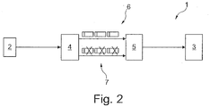
- Ein solcher Fall ist in
Figur 2 dargestellt. Daraus ist erkennbar, dass Daten über die eine Übertragungsstrecke dauerhaft und fehlerfrei übertragen werden, wohingegen die gleichen Daten, die über die weitere Übertragungsstrecke übertragen werden, zu 100 % verloren gehen, weil zum Beispiel diese Übertragungsstrecke vollständig ausgefallen ist. Die 100 % fehlerfrei über die eine Übertragungsstrecke übertragenen Daten kommen bei dem weiteren Netzwerk fehlerfrei an, sodass die Datenübertragung zwar aufrecht erhalten und der Betrieb des Übertragungssystems fehlerfrei gewährleistet ist. Kommt es jedoch zu einer Störung der Übertragungsstrecke, mit der bisher 100 % der Daten übertragen worden sind, wir der Redundanzmechanismus beeinträchtigt oder im schlimmsten Falle sogar vollständig aufgehoben, sodass es in nachteiliger Weise zu kritischen Situationen kommen kann. - Der Erfindung liegt daher die Aufgabe zugrunde, ein Verfahren zum Betreiben eines Übertragungssystems hinsichtlich seiner Sicherheitsreserven zu verbessern.
- Diese Aufgabe ist durch die Merkmale des Patentanspruches 1 gelöst.
- Erfindungsgemäß ist vorgesehen, dass die Daten als Datenpakete übertragen werden und ermittelt wird, ob ein Datenpaket übertragen wurde oder nicht und darauf basierend abgeleitet wird, ob das Übertragungssystem fehlerfrei oder nicht arbeitet. Mit der Lösung der Erfindung kann also festgestellt werden, ob der Redundanzmechanismus arbeitet oder nicht und aufgrund dessen kann eine Aussage abgeleitet werden, ob das Übertragungssystem fehlerfrei oder fehlerbehaftet, das heißt unter Anwendung des Redundanzmechanismus arbeitet. Damit wird für den Anwender die Möglichkeit geschaffen, das Übertragungssystem zu überwachen und möglicherweise Gegenmaßnahmen einzuleiten. Wenn also beispielsweise festgestellt wird, dass alle Datenpakete sowohl über die eine als auch über die weitere Übertragungsstrecke fehlerfrei übertragen worden sind, kann daraus abgeleitet werden, dass das gesamte Übertragungssystem fehlerfrei arbeitet und die erforderliche und gewünschte Redundanzreserve uneingeschränkt zur Verfügung steht. Wird jedoch festgestellt, dass ein Teil der Daten über die eine Übertragungsstrecke und/oder ein Teil der Daten über die weitere Übertragungsstrecke nicht fehlerfrei übertragen wurden (weil zum Beispiel eine der Übertragungsstrecken gestört war oder in Komponenten des Übertragungssystems ein Fehler vorliegt), kann daraus abgeleitet werden, dass das Übertragungssystem zwar nach wie vor Daten von dem einen zu dem anderen Netzwerk übertragen werden kann, das jedoch die Redundanzreserve eingeschränkt ist. Je nachdem, wie groß das Maß der als fehlerhaft oder gar nicht übertragenen Datenpakete festgestellt wurde, kann abgeleitet werden, ob dies noch zulässig ist und die geforderte Redundanzreserve noch nicht unterschritten ist oder ob dies schon der Fall ist, sodass es erforderlich ist, zumindest eine Fehleranalyse oder gegebenenfalls Gegenmaßnahmen einzuleiten.
- In Weiterbildung der Erfindung wird jedes fehlerfrei übertragene Datenpaket gezählt und in Bezug gesetzt zu der Gesamtzahl der übertragenen Datenpakete und daraus eine Ausfallwahrscheinlichkeit berechnet. So ist den Verdopplungsmitteln (Redundancy Box) bekannt, wie groß die Anzahl der Datenpakete ist, die auf eine Übertragungsstrecke geschickt werden. Diese Anzahl kann den Separiermitteln (Redundancy Box) übermittelt werden, wobei diese Separiermittel die fehlerfrei auf dieser Übertragungsstrecke übertragenen und von ihre empfangenen Datenpakete zählt. Diese beiden Zahlen werden in Bezug gesetzt, wobei im Falle der fehlerfreien Übertragung das Bezugsverhältnis gleich 1 ist. Ist es jedoch kleiner 1, ist anzunehmen, dass Datenpakete bei der Übertragung auf der Übertragungsstrecke verloren gegangen sind infolge von Störungen, Ausfällen oder dergleichen. Dann kann entschieden werden, um welches Maß das Verhältnis kleiner 1 ist. Liegt es beispielsweise zwischen 0,9 und 1 oder zwischen 0,8 und 1, kann zwar davon ausgegangen werden, dass die Datenübertragung zwar noch funktioniert, jedoch der Redundanzmechanismus eingesetzt hat. Allerdings ist in diesem Falle die Redundanzreserve (die zum Beispiel bei einem Verhältnis von 0,9 oder 0,8 liegt) noch nicht unterschritten, sodass ein Eingreifen eines Benutzers des Übertragungssystems noch nicht erforderlich ist. Erst wenn diese Redundanzreserve von beispielsweise 0,9 oder 0,8 weiter unterschritten wird, ist ein Eingreifen des Benutzers hinsichtlich einer Fehleranalyse bzw. einer Fehlerbeseitigung nach erfolgter Fehleranalyse erforderlich, obwohl nach wie vor die zuverlässige Datenübertragung zwischen dem ersten und dem weiteren Netzwerk erfolgt. In einem solchen Fall kann trotz weiterer korrekter Datenübertragung einem Ausfall des Übertragungssystems oder einer Beeinträchtigung entgegengewirkt werden. Dies ist unter sicherheitskritischen Aspekten von besonderem Vorteil, da nach der Erfindung Fehler vorausschauend erkannt und dementsprechend gehandelt werden kann.
- In Weiterbildung der Erfindung erfolgt die vorstehend beschriebene Vorgehensweise für jede Übertragungsstrecke separat voneinander. Das heißt, dass für jede Übertragungsstrecke jedes fehlerfrei übertragene Datenpaket gezählt und in Bezug gesetzt wird zu der Gesamtzahl der übertragenen Datenpakete und daraus eine Ausfallwahrscheinlichkeit bzw. die vorstehend genannte Redundanzreserve berechnet wird. In besonders vorteilhafter Weise wird diese Ausfallwahrscheinlichkeit oder die Redundanzreserve angezeigt. Hierzu sind entsprechende Mittel vorgesehen. Diese Mittel können zum Beispiel eine Art Ampel sein, die signalisiert, ob das Übertragungssystem zu 100 % fehlerfrei einschließlich aller Einheiten des Übertragungssystems arbeitet, ohne dass der Redundanzmechanismus eingesetzt hat. Mit entsprechenden Leuchtmitteln könnte dieser Zustand zum Beispiel in grüner Farbe angezeigt werden. Wird jedoch eine gewisse Ausfallwahrscheinlichkeit berechnet, sodass die Redundanzreserve nicht mehr gleich 1 sondern kleiner 1 ist, kann dies durch Leuchtmittel beispielsweise in gelber Farbe angezeigt werden. Dies erfolgt so lange, solange die Redundanzreserve zwar kleiner 1, aber oberhalb einer vorgebbaren Schwelle, die kleiner 1 und größer 0 ist, liegt. Diese Schwelle kann beispielsweise bei dem vorgezeichneten Wert 0,9 oder 0,8 oder davon abweichenden Werten liegen. Auf jeden Fall wird dem Betreiber des Übertragungssystems durch diese Farbe signalisiert, dass der Redundanzmechanismus eingesetzt hat und die Datenübertragung zwar noch fehlerfrei, jedoch hinsichtlich der Redundanz eingeschränkt erfolgt. Er kann daraus ableite, ob er eine Fehleranalyse durchführen und in Abhängigkeit dessen festgestellte Fehler beseitigen will. Festgestellte Fehler können beispielsweise Störungen der Übertragungsstrecke oder auch Hardwarefehler von Komponenten des Übertragungssystems sein. Erst wenn die Ausfallwahrscheinlichkeit eine vorgebbare Schwelle überschreitet, was gleichbedeutend ist mit dem Unterschreiten der Redundanzreserve unterhalb eines Schwellwertes kleiner 1, liegt eine deutlich Einschränkung nicht nur der Datenübertragung, sondern auch der Redundanz vor, sodass daraus sicherheitskritische Zustände entstehen können, wenn dieser Zustand beibehalten wird. Daher ist es nötig, in einem solchen Fall, der durch rote Leuchtmittel signalisiert werden kann, zu handeln, um solche sicherheitskritischen Zustände unbedingt zu vermeiden. Neben der Anzeige, dass eine gewisse Ausfallwahrscheinlichkeit vorliegt, kann auch alternativ oder ergänzen dazu daran gedacht werden, dass dann, wenn die Ausfallwahrscheinlichkeit eine vorgebbare Schwelle überschreitet bzw. die Redundanzreserve einen vorgebbaren Wert kleiner 1 unterschreitet, eine Benachrichtigung ausgelöst wird. Dies kann beispielsweise eine SMS-Nachricht oder vergleichbare Nachricht, eine E-Mail, oder dergleichen sein, die zum Beispiel ein Netzwerk-Administrator erhält.
- Das vorgestellte Verfahren kann auf einem Übertragungssystem, das in der
Figur 1 dargestellt ist, durchgeführt werden. -
Figur 1 zeigt eine prinzipielle Anordnung eines Übertragungssystems, welches zwei Netzwerke 2, 3 aufweist, die untereinander Daten austauschen sollen. Dieser Datenaustausch kann entweder unidirektional von dem Netzwerk 2 zu dem Netzwerk 3 (oder umgekehrt), genauso aber auch bidirektional zwischen den beiden Netzwerken 2, 3 erfolgen. - Bei den Netzwerken 2, 3 kann es sich um einfache oder komplexe Netzwerke, zum Beispiel in einer Ring- oder Linientopologie oder dergleichen, handeln. Es ist aber auch denkbar, dass ein solches Netzwerk 2, 3 nur ein einziges Element wie zum Beispiel einen Sensor, einen Aktor, ein Steuergerät oder dergleichen umfasst.
- Um die Daten des Netzwerkes 2 zum Beispiel zu dem Netzwerk 3 zu Übertragen, sind Verdopplungsmittel 4 vorhanden. Diese Verdopplungsmittel 4 teilen den zugeführten Datenstrom in zwei Datenströme auf. Ebenso erfolgt das Zusammenführen der beiden Datenströme nach deren Empfangen über Separiermittel 5, wobei die empfangenen Datenströme nach dem Zusammenführen an das Netzwerk 3 weitergeleitet werden.
- Die Übertragung der Daten zwischen den Verdopplungsmittel und den Separiermitteln 5 erfolgt über zwei gleichartige oder voneinander unterschiedliche Übertragungsstrecken 6, 7 drahtlos mittels PRP. Die Drahtlosübertragung erfolgt in vorteilhafter Weise über Funkt, wobei eine optische Übertragung auch denkbar ist. Auch denkbar ist, dass die eine Übertragungsstrecke 6 eine Funkübertragungsstrecke und die zweite Übertragungsstrecke 7 eine optische Datenübertragungsstrecke ist. Sind beide Übertragungsstrecken 6, 7 zum Beispiel Funkübertragungsstrecken, können die Daten, genauer die Datenpakete, über diese beiden Funkübertragungsstrecken zum Beispiel auf gleicher Frequenz oder unterschiedlichen Frequenzen und ansonsten gleicher Parameter oder voneinander unterschiedlicher Übertragungsparameter übertragen werden. Gleichartige Übertragungsstrecken 6, 7 sind hinsichtlich ihres Aufbaues zu bevorzugen, wobei voneinander unterschiedliche Übertragungsstrecken 6, 7 (zum Beispiel optisch/Funk bzw. voneinander unterschiedliche Übertragungsparameter) hinsichtlich der Steigerung der Redundanz zu bevorzugen sind.
- Nachdem die Daten von dem Erstnetzwerk 2 den Verdopplungsmitteln 4 (bei PRP auch als Redundancy Box bezeichnet) zugeführt worden sind, wird dort veranlasst, dass jedes Datenpaket mehrfach über die gleiche Übertragungsstrecke 6, 7 übertragen wird und/oder jedem Datenpaket ein Fehlerkorrekturwert zugeordnet wird. Anschließend erfolgt in entsprechender Weise die Übertragung der Datenpakete über die Übertragungsstrecken 6, 7, wobei die von den Separiermitteln 5 (im Falle von PRP auch als Redundancy Box bezeichnet) entsprechend ausgewertet, gegebenenfalls aufbereitet und als Datenpakete dem weiteren Netzwerk 3 zugeführt werden.
- Die vorstehende Beschreibung der
Figur 1 bezieht sich auf eine unidirektionale Datenübertragung von dem Erstnetzwerk 2 zu dem weiteren, insbesondere dem zweiten Netzwerk 3. Hierzu sind die Verdopplungsmittel 4 zum Aufteilen des Datenstromes und die Separiermittel 5 zum Zusammenführen des empfangenen Datenstromes ausgebildet. - Ist auch eine Datenübertragung von dem Netzwerk 3 zu dem Netzwerk 2 gewünscht, können weitere Verdopplungsmittel 4 bzw. Separiermittel 5 in dem Übertragungsweg zwischen dem Netzwerk 3 und dem Netzwerk 2 vorhanden sein, sodass sich ein doppelter Aufbau ergibt. Alternativ dazu können die Mittel 4, 5 auch dazu ausgebildet sein, nicht nur den zugeführten Datenstrom zu verdoppeln, sondern auch die über die Übertragungsstrecken 6, 7 zugeführten Datenströme zu separieren, was ebenso für die Separiermittel 5 gilt.
-
- 1.
- Übertragungssystem
- 2.
- Erstes Netzwerk
- 3.
- Weiteres Netzwerk
- 4.
- Verdopplungsmittel
- 5.
- Separiermittel
- 6.
- Erste Übertragungsstrecke
- 7.
- Zweite Übertragungsstrecke
Claims (5)
- Verfahren zum Betreiben eines Übertragungssystemes (1), das ein erstes Netzwerk (2) und zumindest ein weiteres Netzwerk (3) aufweist, wobei zwischen diesen zumindest zwei Netzwerken (2, 3) dadurch Daten ausgetauscht werden, dass Daten des ersten Netzwerkes (2) Verdopplungsmitteln (4) zugeführt werden, wobei die zugeführten Daten durch die Verdopplungsmittel in zwei Datenströme aufgeteilt werden und über zumindest zwei Übertragungsstrecken (6, 7) drahtlos mittels Parallel Redundancy Protocol, PRP, zu Separiermitteln (5) übertragen und von den Separiermitteln (5) an das angeschlossene weitere Netzwerk (3) weitergeleitet werden, wobei die Daten als Datenpakete übertragen werden und ermittelt wird, ob ein Datenpaket übertragen wurde oder nicht und darauf basierend abgeleitet wird, ob das Übertragungssystem (1) fehlerfrei oder nicht arbeitet.
- Verfahren nach Anspruch 1, wobei jedes fehlerfrei übertragene Datenpaket gezählt und in Bezug gesetzt wird zu der Gesamtzahl der übertragenen Datenpakete und daraus eine Ausfallwahrscheinlichkeit berechnet wird.
- Verfahren nach Anspruch 2, wobei für jede Übertragungsstrecke (6, 7) jedes fehlerfrei übertragene Datenpaket gezählt und in Bezug gesetzt wird zu der Gesamtzahl der übertragenen Datenpaket und daraus eine Ausfallwahrscheinlichkeit berechnet wird.
- Verfahren nach Anspruch 2 oder 3, wobei die Ausfallwahrscheinlichkeit angezeigt wird.
- Verfahren nach Anspruch 2, 3 oder 4, wobei dann, wenn die Ausfallwahrscheinlichkeit eine vorgebbare Schwelle überschreitet, eine Benachrichtigung ausgelöst wird.
Applications Claiming Priority (2)
| Application Number | Priority Date | Filing Date | Title |
|---|---|---|---|
| DE102014206873 | 2014-04-09 | ||
| PCT/EP2015/057786 WO2015155315A1 (de) | 2014-04-09 | 2015-04-09 | Verfahren für ein redundantes übertragungssystem mit prp und fehlvorhersage |
Publications (2)
| Publication Number | Publication Date |
|---|---|
| EP3130100A1 EP3130100A1 (de) | 2017-02-15 |
| EP3130100B1 true EP3130100B1 (de) | 2021-10-20 |
Family
ID=53008456
Family Applications (3)
| Application Number | Title | Priority Date | Filing Date |
|---|---|---|---|
| EP15719973.8A Active EP3130099B1 (de) | 2014-04-09 | 2015-04-09 | Verfahren für ein redundantes übertragungssystem mit prp und energieeinsparung |
| EP15718810.3A Active EP3130100B1 (de) | 2014-04-09 | 2015-04-09 | Verfahren für ein redundantes übertragungssystem mit prp und fehlvorhersage |
| EP15718809.5A Active EP3130097B1 (de) | 2014-04-09 | 2015-04-09 | Verfahren für ein redundantes übertragungssystem mit prp und mehrfachem datenpaketversand |
Family Applications Before (1)
| Application Number | Title | Priority Date | Filing Date |
|---|---|---|---|
| EP15719973.8A Active EP3130099B1 (de) | 2014-04-09 | 2015-04-09 | Verfahren für ein redundantes übertragungssystem mit prp und energieeinsparung |
Family Applications After (1)
| Application Number | Title | Priority Date | Filing Date |
|---|---|---|---|
| EP15718809.5A Active EP3130097B1 (de) | 2014-04-09 | 2015-04-09 | Verfahren für ein redundantes übertragungssystem mit prp und mehrfachem datenpaketversand |
Country Status (4)
| Country | Link |
|---|---|
| US (3) | US20190199485A1 (de) |
| EP (3) | EP3130099B1 (de) |
| DE (3) | DE102015206380A1 (de) |
| WO (3) | WO2015155316A1 (de) |
Families Citing this family (5)
| Publication number | Priority date | Publication date | Assignee | Title |
|---|---|---|---|---|
| DE102016215640A1 (de) * | 2016-08-19 | 2018-02-22 | Robert Bosch Gmbh | Verfahren, Sensor und Steuergerät zum Übertragen eines Datenpakets von einem Sensor zu einem Steuergerät |
| DE102017005131A1 (de) * | 2017-05-30 | 2018-12-06 | Diehl Metering Systems Gmbh | Verfahren zur Übertragung einer Information |
| US11265208B1 (en) * | 2020-12-29 | 2022-03-01 | Honeywell International Inc. | Detecting path faults in parallel redundancy protocol communications |
| US20230269062A1 (en) * | 2022-02-18 | 2023-08-24 | Sony Semiconductor Solutions Corporation | Communication apparatus and communication system |
| EP4354772A1 (de) * | 2022-10-11 | 2024-04-17 | Nxp B.V. | Netzwerkvorrichtung, kommunikationssystem und verfahren für die netzwerkvorrichtung |
Family Cites Families (35)
| Publication number | Priority date | Publication date | Assignee | Title |
|---|---|---|---|---|
| US5933567A (en) * | 1993-01-13 | 1999-08-03 | Hitachi America, Ltd. | Method and apparatus for controlling the position of the heads of a digital video tape recorder during trick play operation and for recording digital data on a tape |
| US5805762A (en) * | 1993-01-13 | 1998-09-08 | Hitachi America, Ltd. | Video recording device compatible transmitter |
| DE19833292A1 (de) | 1998-07-24 | 2000-01-27 | Dornier Medtech Holding Int Gmbh | Verfahren zur kontaktlosen Übertragung von Daten und Vorrichtung zur Durchführung desselben |
| US7965729B2 (en) * | 2001-05-23 | 2011-06-21 | Polytechnic University | Transferring data such as files |
| US7787389B2 (en) * | 2001-08-20 | 2010-08-31 | Qualcomm Incorporated | Method and system for utilization of an outer decoder in a broadcast services communication system |
| EP1506621B1 (de) * | 2002-06-11 | 2013-01-02 | Digital Fountain, Inc. | Decodieren von kettenreaktionscodes durch inaktivierung wiederhergestellter symbole |
| US6948104B2 (en) * | 2002-06-26 | 2005-09-20 | Microsoft Corporation | System and method for transparent electronic data transfer using error correction to facilitate bandwidth-efficient data recovery |
| US7984174B2 (en) * | 2002-11-11 | 2011-07-19 | Supracomm, Tm Inc. | Multicast videoconferencing |
| US7188189B2 (en) * | 2003-04-02 | 2007-03-06 | Avaya Technology Corp. | System and method to improve the resiliency and performance of enterprise networks by utilizing in-built network redundancy |
| JP2006086890A (ja) * | 2004-09-16 | 2006-03-30 | Fujitsu Ltd | ネットワークシステム、データ送信装置、端末装置および同報通信方法 |
| FR2880491A1 (fr) * | 2005-01-06 | 2006-07-07 | Thomson Licensing Sa | Methode de transmission d'un flux multipoint dans un reseau local et dispositif de connexion implementant la methode |
| US7590756B2 (en) * | 2005-05-13 | 2009-09-15 | Itt Manufacturing Enterprises, Inc. | Method and system for transferring data in a communications network using redundant communication paths |
| US7653055B2 (en) * | 2006-03-31 | 2010-01-26 | Alcatel-Lucent Usa Inc. | Method and apparatus for improved multicast streaming in wireless networks |
| US8358704B2 (en) * | 2006-04-04 | 2013-01-22 | Qualcomm Incorporated | Frame level multimedia decoding with frame information table |
| GB2441164A (en) | 2006-08-22 | 2008-02-27 | Iti Scotland Ltd | Segmenting packets and providing error check portions for each segment |
| EP2015501A1 (de) * | 2007-07-09 | 2009-01-14 | ABB Technology AG | Identifizierung unsachgemäßer Verdrahtung von Vorrichtungen |
| KR101486372B1 (ko) * | 2007-07-25 | 2015-01-26 | 엘지전자 주식회사 | 디지털 방송 시스템 및 데이터 처리 방법 |
| US8392791B2 (en) * | 2008-08-08 | 2013-03-05 | George Saliba | Unified data protection and data de-duplication in a storage system |
| CN102036061B (zh) * | 2009-09-30 | 2012-11-21 | 华为技术有限公司 | 视频数据传输处理、发送处理方法、装置和网络系统 |
| US8443261B2 (en) * | 2009-12-11 | 2013-05-14 | Vmware, Inc. | Transparent recovery from hardware memory errors |
| US8542593B1 (en) * | 2010-03-19 | 2013-09-24 | Vucast Media, Inc. | System and methods for error tolerant content delivery over multicast channels |
| US8862944B2 (en) | 2010-06-24 | 2014-10-14 | International Business Machines Corporation | Isolation of faulty links in a transmission medium |
| WO2011160957A1 (en) * | 2010-06-24 | 2011-12-29 | International Business Machines Corporation | Isolation of faulty links in a transmission medium |
| US8631272B2 (en) * | 2011-03-04 | 2014-01-14 | Microsoft Corporation | Duplicate-aware disk arrays |
| US8547845B2 (en) * | 2011-05-24 | 2013-10-01 | International Business Machines Corporation | Soft error recovery for converged networks |
| WO2012168262A1 (de) * | 2011-06-10 | 2012-12-13 | Hirschmann Automation And Control Gmbh | Komplett redundante verbindung und handover bei zellularen industriellen funknetzwerken |
| DE102011084344A1 (de) | 2011-10-12 | 2013-04-18 | Siemens Aktiengesellschaft | Verfahren zur Laufzeitoptimierung bei paketorientierter Mobilfunkübertragung von Datentelegrammen |
| EP2634973B1 (de) * | 2012-02-29 | 2014-10-01 | Siemens Aktiengesellschaft | Kommunikationsgerät für ein redundant betreibbares industrielles Kommunikationsnetz und Verfahren zum Betrieb eines Kommunikationsgeräts |
| EP2867891B1 (de) * | 2012-06-28 | 2016-12-28 | ANT - Advanced Network Technologies OY | Verarbeitung und fehlerverschleierung von digitalen signalen |
| US9060252B2 (en) * | 2012-07-31 | 2015-06-16 | International Business Machines Corporation | Rate adaptive transmission of wireless broadcast packets |
| US9019843B2 (en) * | 2012-09-13 | 2015-04-28 | International Business Machines Corporation | Utilizing stored data to reduce packet data loss in a mobile data network with data breakout at the edge |
| RU2527210C1 (ru) * | 2013-06-14 | 2014-08-27 | Общество с ограниченной ответственностью "Новые технологии презентаций" | Способ и система для передачи данных от веб-сервера клиентским терминальным устройствам посредством локальной беспроводной коммуникационной сети |
| US9081684B2 (en) * | 2013-08-28 | 2015-07-14 | Landis+Gyr Technologies, Llc | Data recovery of data symbols received in error |
| FI128272B (en) * | 2014-12-16 | 2020-02-14 | Valmet Automation Oy | Redundancy in the process control system |
| KR20170029212A (ko) * | 2015-09-07 | 2017-03-15 | (주) 유파인스 | 이중화 리던던시 기능을 가진 네트워크 장치 |
-
2015
- 2015-04-09 DE DE102015206380.1A patent/DE102015206380A1/de not_active Ceased
- 2015-04-09 WO PCT/EP2015/057787 patent/WO2015155316A1/de not_active Ceased
- 2015-04-09 US US15/302,241 patent/US20190199485A1/en not_active Abandoned
- 2015-04-09 EP EP15719973.8A patent/EP3130099B1/de active Active
- 2015-04-09 EP EP15718810.3A patent/EP3130100B1/de active Active
- 2015-04-09 WO PCT/EP2015/057784 patent/WO2015155314A1/de not_active Ceased
- 2015-04-09 DE DE102015206382.8A patent/DE102015206382A1/de not_active Ceased
- 2015-04-09 DE DE102015206383.6A patent/DE102015206383A1/de not_active Ceased
- 2015-04-09 WO PCT/EP2015/057786 patent/WO2015155315A1/de not_active Ceased
- 2015-04-09 US US15/302,208 patent/US10404416B2/en active Active
- 2015-04-09 US US15/302,191 patent/US11296834B2/en active Active
- 2015-04-09 EP EP15718809.5A patent/EP3130097B1/de active Active
Non-Patent Citations (1)
| Title |
|---|
| None * |
Also Published As
| Publication number | Publication date |
|---|---|
| EP3130097A1 (de) | 2017-02-15 |
| WO2015155315A1 (de) | 2015-10-15 |
| DE102015206383A1 (de) | 2015-10-15 |
| EP3130099B1 (de) | 2022-12-21 |
| US10404416B2 (en) | 2019-09-03 |
| US20180351702A1 (en) | 2018-12-06 |
| US11296834B2 (en) | 2022-04-05 |
| US20190199485A1 (en) | 2019-06-27 |
| DE102015206380A1 (de) | 2015-10-15 |
| WO2015155316A1 (de) | 2015-10-15 |
| EP3130100A1 (de) | 2017-02-15 |
| DE102015206382A1 (de) | 2015-10-15 |
| EP3130097B1 (de) | 2024-11-27 |
| WO2015155314A1 (de) | 2015-10-15 |
| US20180262298A1 (en) | 2018-09-13 |
| EP3130099A1 (de) | 2017-02-15 |
Similar Documents
| Publication | Publication Date | Title |
|---|---|---|
| EP2838220A1 (de) | Verfahren zur redundanten Nachrichtenübermittlung in einem industriellen Kommunikationsnetz und Kommunikationsgerät | |
| EP3130100A1 (de) | Verfahren für ein redundantes übertragungssystem mit prp und fehlvorhersage | |
| EP2613463B1 (de) | Verfahren zur überwachung eines transmitters und entsprechender transmitter | |
| EP1365543B1 (de) | Verfahren und Vorrichtung zur Übertragung von Information und Fehlererkennung in einem ringförmigen Netzwerk | |
| DE102011086726B4 (de) | Verfahren zur redundanten Kommunikation zwischen einem Nutzer-Terminal und einem Leitsystem-Server | |
| DE3701714A1 (de) | Verfahren und vorrichtung zur ueberwachung rechnergesteuerter stellglieder | |
| EP3020162A1 (de) | Semantische deduplikation | |
| WO2016193443A1 (de) | Verfahren für ein redundantes übertragungssystem mit prp und zwischenspeicherung von datenpaketen | |
| WO2015043817A1 (de) | Filtern eines datenpaketes durch eine netzwerkfiltereinrichtung | |
| EP3556060B1 (de) | Verfahren zur optimierung der ausfallerkennung von redundanz-protokollen mit testdatenpaketen | |
| DE102011082598A1 (de) | Steueranordnung | |
| DE102010045683A1 (de) | Kombinierte Unicast/Multicast Softwareübertragung | |
| EP0059789A2 (de) | Einrichtung zur Funktionsprüfung eines Mehrrechnersystems | |
| DE102007007537A1 (de) | Leitsystem einer technischen Anlage | |
| DE102012004854A1 (de) | Verfahren zum effizienten Betrieb eines überwachten Telekommmunikationsnetzes mit Hilfe eines Netzmanagementsystems, von Computerprogrammen und Computerprogrammprodukten | |
| DE102018221417B4 (de) | Fahrzeug mit einem Netzwerkverteiler zum Melden einer Störung in einem Kommunikationsnetzwerk | |
| EP3457232B1 (de) | Verfahren zum betrieb eines hochverfügbaren automatisierungssystems | |
| EP3761179B1 (de) | Verfahren zur überprüfung der funktion eines prozessors durch einen watchdog | |
| WO2012175202A2 (de) | Verfahren zur rückwirkungsfreien, redundanten kopplung von kommunikationsnetzen mittels des rapid spanning tree protocols | |
| DE102006042131B4 (de) | Rechnersystem | |
| DE102012001624B4 (de) | Störungstolerantes Saftey-at-Work System | |
| DE2831960C2 (de) | Sicherungseinrichtung für die empfangsseitige Auswerteschaltung einer Datenübertragungsanlage mit sich paarweise ausschließenden Informationen | |
| DE102020111450A1 (de) | Erkennen von Fehlern in einem Computernetzwerk | |
| EP1751634B1 (de) | Verfahren zur überwachung eines verbundes von steuergeräten | |
| DE102016113324A1 (de) | Ethernet-Netzwerk |
Legal Events
| Date | Code | Title | Description |
|---|---|---|---|
| STAA | Information on the status of an ep patent application or granted ep patent |
Free format text: STATUS: THE INTERNATIONAL PUBLICATION HAS BEEN MADE |
|
| PUAI | Public reference made under article 153(3) epc to a published international application that has entered the european phase |
Free format text: ORIGINAL CODE: 0009012 |
|
| STAA | Information on the status of an ep patent application or granted ep patent |
Free format text: STATUS: REQUEST FOR EXAMINATION WAS MADE |
|
| 17P | Request for examination filed |
Effective date: 20161007 |
|
| AK | Designated contracting states |
Kind code of ref document: A1 Designated state(s): AL AT BE BG CH CY CZ DE DK EE ES FI FR GB GR HR HU IE IS IT LI LT LU LV MC MK MT NL NO PL PT RO RS SE SI SK SM TR |
|
| AX | Request for extension of the european patent |
Extension state: BA ME |
|
| DAV | Request for validation of the european patent (deleted) | ||
| DAX | Request for extension of the european patent (deleted) | ||
| STAA | Information on the status of an ep patent application or granted ep patent |
Free format text: STATUS: EXAMINATION IS IN PROGRESS |
|
| 17Q | First examination report despatched |
Effective date: 20190911 |
|
| GRAP | Despatch of communication of intention to grant a patent |
Free format text: ORIGINAL CODE: EPIDOSNIGR1 |
|
| STAA | Information on the status of an ep patent application or granted ep patent |
Free format text: STATUS: GRANT OF PATENT IS INTENDED |
|
| INTG | Intention to grant announced |
Effective date: 20210611 |
|
| GRAS | Grant fee paid |
Free format text: ORIGINAL CODE: EPIDOSNIGR3 |
|
| GRAA | (expected) grant |
Free format text: ORIGINAL CODE: 0009210 |
|
| STAA | Information on the status of an ep patent application or granted ep patent |
Free format text: STATUS: THE PATENT HAS BEEN GRANTED |
|
| AK | Designated contracting states |
Kind code of ref document: B1 Designated state(s): AL AT BE BG CH CY CZ DE DK EE ES FI FR GB GR HR HU IE IS IT LI LT LU LV MC MK MT NL NO PL PT RO RS SE SI SK SM TR |
|
| REG | Reference to a national code |
Ref country code: GB Ref legal event code: FG4D Free format text: NOT ENGLISH |
|
| REG | Reference to a national code |
Ref country code: CH Ref legal event code: EP |
|
| REG | Reference to a national code |
Ref country code: DE Ref legal event code: R096 Ref document number: 502015015319 Country of ref document: DE |
|
| REG | Reference to a national code |
Ref country code: IE Ref legal event code: FG4D Free format text: LANGUAGE OF EP DOCUMENT: GERMAN |
|
| REG | Reference to a national code |
Ref country code: AT Ref legal event code: REF Ref document number: 1440805 Country of ref document: AT Kind code of ref document: T Effective date: 20211115 |
|
| REG | Reference to a national code |
Ref country code: LT Ref legal event code: MG9D |
|
| REG | Reference to a national code |
Ref country code: NL Ref legal event code: MP Effective date: 20211020 |
|
| PG25 | Lapsed in a contracting state [announced via postgrant information from national office to epo] |
Ref country code: RS Free format text: LAPSE BECAUSE OF FAILURE TO SUBMIT A TRANSLATION OF THE DESCRIPTION OR TO PAY THE FEE WITHIN THE PRESCRIBED TIME-LIMIT Effective date: 20211020 Ref country code: LT Free format text: LAPSE BECAUSE OF FAILURE TO SUBMIT A TRANSLATION OF THE DESCRIPTION OR TO PAY THE FEE WITHIN THE PRESCRIBED TIME-LIMIT Effective date: 20211020 Ref country code: FI Free format text: LAPSE BECAUSE OF FAILURE TO SUBMIT A TRANSLATION OF THE DESCRIPTION OR TO PAY THE FEE WITHIN THE PRESCRIBED TIME-LIMIT Effective date: 20211020 Ref country code: BG Free format text: LAPSE BECAUSE OF FAILURE TO SUBMIT A TRANSLATION OF THE DESCRIPTION OR TO PAY THE FEE WITHIN THE PRESCRIBED TIME-LIMIT Effective date: 20220120 |
|
| PG25 | Lapsed in a contracting state [announced via postgrant information from national office to epo] |
Ref country code: IS Free format text: LAPSE BECAUSE OF FAILURE TO SUBMIT A TRANSLATION OF THE DESCRIPTION OR TO PAY THE FEE WITHIN THE PRESCRIBED TIME-LIMIT Effective date: 20220220 Ref country code: SE Free format text: LAPSE BECAUSE OF FAILURE TO SUBMIT A TRANSLATION OF THE DESCRIPTION OR TO PAY THE FEE WITHIN THE PRESCRIBED TIME-LIMIT Effective date: 20211020 Ref country code: PT Free format text: LAPSE BECAUSE OF FAILURE TO SUBMIT A TRANSLATION OF THE DESCRIPTION OR TO PAY THE FEE WITHIN THE PRESCRIBED TIME-LIMIT Effective date: 20220221 Ref country code: PL Free format text: LAPSE BECAUSE OF FAILURE TO SUBMIT A TRANSLATION OF THE DESCRIPTION OR TO PAY THE FEE WITHIN THE PRESCRIBED TIME-LIMIT Effective date: 20211020 Ref country code: NO Free format text: LAPSE BECAUSE OF FAILURE TO SUBMIT A TRANSLATION OF THE DESCRIPTION OR TO PAY THE FEE WITHIN THE PRESCRIBED TIME-LIMIT Effective date: 20220120 Ref country code: NL Free format text: LAPSE BECAUSE OF FAILURE TO SUBMIT A TRANSLATION OF THE DESCRIPTION OR TO PAY THE FEE WITHIN THE PRESCRIBED TIME-LIMIT Effective date: 20211020 Ref country code: LV Free format text: LAPSE BECAUSE OF FAILURE TO SUBMIT A TRANSLATION OF THE DESCRIPTION OR TO PAY THE FEE WITHIN THE PRESCRIBED TIME-LIMIT Effective date: 20211020 Ref country code: HR Free format text: LAPSE BECAUSE OF FAILURE TO SUBMIT A TRANSLATION OF THE DESCRIPTION OR TO PAY THE FEE WITHIN THE PRESCRIBED TIME-LIMIT Effective date: 20211020 Ref country code: GR Free format text: LAPSE BECAUSE OF FAILURE TO SUBMIT A TRANSLATION OF THE DESCRIPTION OR TO PAY THE FEE WITHIN THE PRESCRIBED TIME-LIMIT Effective date: 20220121 Ref country code: ES Free format text: LAPSE BECAUSE OF FAILURE TO SUBMIT A TRANSLATION OF THE DESCRIPTION OR TO PAY THE FEE WITHIN THE PRESCRIBED TIME-LIMIT Effective date: 20211020 |
|
| REG | Reference to a national code |
Ref country code: DE Ref legal event code: R097 Ref document number: 502015015319 Country of ref document: DE |
|
| PG25 | Lapsed in a contracting state [announced via postgrant information from national office to epo] |
Ref country code: SM Free format text: LAPSE BECAUSE OF FAILURE TO SUBMIT A TRANSLATION OF THE DESCRIPTION OR TO PAY THE FEE WITHIN THE PRESCRIBED TIME-LIMIT Effective date: 20211020 Ref country code: SK Free format text: LAPSE BECAUSE OF FAILURE TO SUBMIT A TRANSLATION OF THE DESCRIPTION OR TO PAY THE FEE WITHIN THE PRESCRIBED TIME-LIMIT Effective date: 20211020 Ref country code: RO Free format text: LAPSE BECAUSE OF FAILURE TO SUBMIT A TRANSLATION OF THE DESCRIPTION OR TO PAY THE FEE WITHIN THE PRESCRIBED TIME-LIMIT Effective date: 20211020 Ref country code: EE Free format text: LAPSE BECAUSE OF FAILURE TO SUBMIT A TRANSLATION OF THE DESCRIPTION OR TO PAY THE FEE WITHIN THE PRESCRIBED TIME-LIMIT Effective date: 20211020 Ref country code: DK Free format text: LAPSE BECAUSE OF FAILURE TO SUBMIT A TRANSLATION OF THE DESCRIPTION OR TO PAY THE FEE WITHIN THE PRESCRIBED TIME-LIMIT Effective date: 20211020 Ref country code: CZ Free format text: LAPSE BECAUSE OF FAILURE TO SUBMIT A TRANSLATION OF THE DESCRIPTION OR TO PAY THE FEE WITHIN THE PRESCRIBED TIME-LIMIT Effective date: 20211020 |
|
| PLBE | No opposition filed within time limit |
Free format text: ORIGINAL CODE: 0009261 |
|
| STAA | Information on the status of an ep patent application or granted ep patent |
Free format text: STATUS: NO OPPOSITION FILED WITHIN TIME LIMIT |
|
| 26N | No opposition filed |
Effective date: 20220721 |
|
| PG25 | Lapsed in a contracting state [announced via postgrant information from national office to epo] |
Ref country code: AL Free format text: LAPSE BECAUSE OF FAILURE TO SUBMIT A TRANSLATION OF THE DESCRIPTION OR TO PAY THE FEE WITHIN THE PRESCRIBED TIME-LIMIT Effective date: 20211020 |
|
| PG25 | Lapsed in a contracting state [announced via postgrant information from national office to epo] |
Ref country code: SI Free format text: LAPSE BECAUSE OF FAILURE TO SUBMIT A TRANSLATION OF THE DESCRIPTION OR TO PAY THE FEE WITHIN THE PRESCRIBED TIME-LIMIT Effective date: 20211020 |
|
| REG | Reference to a national code |
Ref country code: CH Ref legal event code: PL |
|
| REG | Reference to a national code |
Ref country code: BE Ref legal event code: MM Effective date: 20220430 |
|
| PG25 | Lapsed in a contracting state [announced via postgrant information from national office to epo] |
Ref country code: MC Free format text: LAPSE BECAUSE OF FAILURE TO SUBMIT A TRANSLATION OF THE DESCRIPTION OR TO PAY THE FEE WITHIN THE PRESCRIBED TIME-LIMIT Effective date: 20211020 Ref country code: LU Free format text: LAPSE BECAUSE OF NON-PAYMENT OF DUE FEES Effective date: 20220409 Ref country code: LI Free format text: LAPSE BECAUSE OF NON-PAYMENT OF DUE FEES Effective date: 20220430 Ref country code: FR Free format text: LAPSE BECAUSE OF NON-PAYMENT OF DUE FEES Effective date: 20220430 Ref country code: CH Free format text: LAPSE BECAUSE OF NON-PAYMENT OF DUE FEES Effective date: 20220430 |
|
| PG25 | Lapsed in a contracting state [announced via postgrant information from national office to epo] |
Ref country code: BE Free format text: LAPSE BECAUSE OF NON-PAYMENT OF DUE FEES Effective date: 20220430 |
|
| PG25 | Lapsed in a contracting state [announced via postgrant information from national office to epo] |
Ref country code: IE Free format text: LAPSE BECAUSE OF NON-PAYMENT OF DUE FEES Effective date: 20220409 |
|
| PG25 | Lapsed in a contracting state [announced via postgrant information from national office to epo] |
Ref country code: IT Free format text: LAPSE BECAUSE OF FAILURE TO SUBMIT A TRANSLATION OF THE DESCRIPTION OR TO PAY THE FEE WITHIN THE PRESCRIBED TIME-LIMIT Effective date: 20211020 |
|
| REG | Reference to a national code |
Ref country code: AT Ref legal event code: MM01 Ref document number: 1440805 Country of ref document: AT Kind code of ref document: T Effective date: 20220409 |
|
| PG25 | Lapsed in a contracting state [announced via postgrant information from national office to epo] |
Ref country code: AT Free format text: LAPSE BECAUSE OF NON-PAYMENT OF DUE FEES Effective date: 20220409 |
|
| PG25 | Lapsed in a contracting state [announced via postgrant information from national office to epo] |
Ref country code: HU Free format text: LAPSE BECAUSE OF FAILURE TO SUBMIT A TRANSLATION OF THE DESCRIPTION OR TO PAY THE FEE WITHIN THE PRESCRIBED TIME-LIMIT; INVALID AB INITIO Effective date: 20150409 |
|
| PG25 | Lapsed in a contracting state [announced via postgrant information from national office to epo] |
Ref country code: MK Free format text: LAPSE BECAUSE OF FAILURE TO SUBMIT A TRANSLATION OF THE DESCRIPTION OR TO PAY THE FEE WITHIN THE PRESCRIBED TIME-LIMIT Effective date: 20211020 Ref country code: CY Free format text: LAPSE BECAUSE OF FAILURE TO SUBMIT A TRANSLATION OF THE DESCRIPTION OR TO PAY THE FEE WITHIN THE PRESCRIBED TIME-LIMIT Effective date: 20211020 |
|
| PG25 | Lapsed in a contracting state [announced via postgrant information from national office to epo] |
Ref country code: TR Free format text: LAPSE BECAUSE OF FAILURE TO SUBMIT A TRANSLATION OF THE DESCRIPTION OR TO PAY THE FEE WITHIN THE PRESCRIBED TIME-LIMIT Effective date: 20211020 |
|
| PG25 | Lapsed in a contracting state [announced via postgrant information from national office to epo] |
Ref country code: MT Free format text: LAPSE BECAUSE OF FAILURE TO SUBMIT A TRANSLATION OF THE DESCRIPTION OR TO PAY THE FEE WITHIN THE PRESCRIBED TIME-LIMIT Effective date: 20211020 |
|
| PGFP | Annual fee paid to national office [announced via postgrant information from national office to epo] |
Ref country code: DE Payment date: 20250422 Year of fee payment: 11 |
|
| PGFP | Annual fee paid to national office [announced via postgrant information from national office to epo] |
Ref country code: GB Payment date: 20250423 Year of fee payment: 11 |