EP3129805B1 - Laserscanner und verfahren - Google Patents
Laserscanner und verfahren Download PDFInfo
- Publication number
- EP3129805B1 EP3129805B1 EP15716769.3A EP15716769A EP3129805B1 EP 3129805 B1 EP3129805 B1 EP 3129805B1 EP 15716769 A EP15716769 A EP 15716769A EP 3129805 B1 EP3129805 B1 EP 3129805B1
- Authority
- EP
- European Patent Office
- Prior art keywords
- thermographic
- data
- laser scanner
- camera
- capturing
- Prior art date
- Legal status (The legal status is an assumption and is not a legal conclusion. Google has not performed a legal analysis and makes no representation as to the accuracy of the status listed.)
- Active
Links
Images




Classifications
-
- G—PHYSICS
- G01—MEASURING; TESTING
- G01S—RADIO DIRECTION-FINDING; RADIO NAVIGATION; DETERMINING DISTANCE OR VELOCITY BY USE OF RADIO WAVES; LOCATING OR PRESENCE-DETECTING BY USE OF THE REFLECTION OR RERADIATION OF RADIO WAVES; ANALOGOUS ARRANGEMENTS USING OTHER WAVES
- G01S17/00—Systems using the reflection or reradiation of electromagnetic waves other than radio waves, e.g. lidar systems
- G01S17/02—Systems using the reflection of electromagnetic waves other than radio waves
- G01S17/06—Systems determining position data of a target
- G01S17/42—Simultaneous measurement of distance and other co-ordinates
-
- G—PHYSICS
- G01—MEASURING; TESTING
- G01J—MEASUREMENT OF INTENSITY, VELOCITY, SPECTRAL CONTENT, POLARISATION, PHASE OR PULSE CHARACTERISTICS OF INFRARED, VISIBLE OR ULTRAVIOLET LIGHT; COLORIMETRY; RADIATION PYROMETRY
- G01J5/00—Radiation pyrometry, e.g. infrared or optical thermometry
- G01J5/02—Constructional details
- G01J5/0205—Mechanical elements; Supports for optical elements
-
- G—PHYSICS
- G01—MEASURING; TESTING
- G01J—MEASUREMENT OF INTENSITY, VELOCITY, SPECTRAL CONTENT, POLARISATION, PHASE OR PULSE CHARACTERISTICS OF INFRARED, VISIBLE OR ULTRAVIOLET LIGHT; COLORIMETRY; RADIATION PYROMETRY
- G01J5/00—Radiation pyrometry, e.g. infrared or optical thermometry
- G01J5/02—Constructional details
- G01J5/025—Interfacing a pyrometer to an external device or network; User interface
-
- G—PHYSICS
- G01—MEASURING; TESTING
- G01J—MEASUREMENT OF INTENSITY, VELOCITY, SPECTRAL CONTENT, POLARISATION, PHASE OR PULSE CHARACTERISTICS OF INFRARED, VISIBLE OR ULTRAVIOLET LIGHT; COLORIMETRY; RADIATION PYROMETRY
- G01J5/00—Radiation pyrometry, e.g. infrared or optical thermometry
- G01J5/02—Constructional details
- G01J5/04—Casings
- G01J5/047—Mobile mounting; Scanning arrangements
-
- G—PHYSICS
- G01—MEASURING; TESTING
- G01J—MEASUREMENT OF INTENSITY, VELOCITY, SPECTRAL CONTENT, POLARISATION, PHASE OR PULSE CHARACTERISTICS OF INFRARED, VISIBLE OR ULTRAVIOLET LIGHT; COLORIMETRY; RADIATION PYROMETRY
- G01J5/00—Radiation pyrometry, e.g. infrared or optical thermometry
- G01J5/02—Constructional details
- G01J5/07—Arrangements for adjusting the solid angle of collected radiation, e.g. adjusting or orienting field of view, tracking position or encoding angular position
-
- G—PHYSICS
- G01—MEASURING; TESTING
- G01J—MEASUREMENT OF INTENSITY, VELOCITY, SPECTRAL CONTENT, POLARISATION, PHASE OR PULSE CHARACTERISTICS OF INFRARED, VISIBLE OR ULTRAVIOLET LIGHT; COLORIMETRY; RADIATION PYROMETRY
- G01J5/00—Radiation pyrometry, e.g. infrared or optical thermometry
- G01J5/02—Constructional details
- G01J5/08—Optical arrangements
- G01J5/0859—Sighting arrangements, e.g. cameras
-
- G—PHYSICS
- G01—MEASURING; TESTING
- G01J—MEASUREMENT OF INTENSITY, VELOCITY, SPECTRAL CONTENT, POLARISATION, PHASE OR PULSE CHARACTERISTICS OF INFRARED, VISIBLE OR ULTRAVIOLET LIGHT; COLORIMETRY; RADIATION PYROMETRY
- G01J5/00—Radiation pyrometry, e.g. infrared or optical thermometry
- G01J5/02—Constructional details
- G01J5/08—Optical arrangements
- G01J5/0896—Optical arrangements using a light source, e.g. for illuminating a surface
-
- G—PHYSICS
- G01—MEASURING; TESTING
- G01S—RADIO DIRECTION-FINDING; RADIO NAVIGATION; DETERMINING DISTANCE OR VELOCITY BY USE OF RADIO WAVES; LOCATING OR PRESENCE-DETECTING BY USE OF THE REFLECTION OR RERADIATION OF RADIO WAVES; ANALOGOUS ARRANGEMENTS USING OTHER WAVES
- G01S17/00—Systems using the reflection or reradiation of electromagnetic waves other than radio waves, e.g. lidar systems
- G01S17/86—Combinations of lidar systems with systems other than lidar, radar or sonar, e.g. with direction finders
-
- G—PHYSICS
- G01—MEASURING; TESTING
- G01S—RADIO DIRECTION-FINDING; RADIO NAVIGATION; DETERMINING DISTANCE OR VELOCITY BY USE OF RADIO WAVES; LOCATING OR PRESENCE-DETECTING BY USE OF THE REFLECTION OR RERADIATION OF RADIO WAVES; ANALOGOUS ARRANGEMENTS USING OTHER WAVES
- G01S17/00—Systems using the reflection or reradiation of electromagnetic waves other than radio waves, e.g. lidar systems
- G01S17/88—Lidar systems specially adapted for specific applications
- G01S17/89—Lidar systems specially adapted for specific applications for mapping or imaging
-
- G—PHYSICS
- G01—MEASURING; TESTING
- G01S—RADIO DIRECTION-FINDING; RADIO NAVIGATION; DETERMINING DISTANCE OR VELOCITY BY USE OF RADIO WAVES; LOCATING OR PRESENCE-DETECTING BY USE OF THE REFLECTION OR RERADIATION OF RADIO WAVES; ANALOGOUS ARRANGEMENTS USING OTHER WAVES
- G01S7/00—Details of systems according to groups G01S13/00, G01S15/00, G01S17/00
- G01S7/48—Details of systems according to groups G01S13/00, G01S15/00, G01S17/00 of systems according to group G01S17/00
- G01S7/481—Constructional features, e.g. arrangements of optical elements
- G01S7/4817—Constructional features, e.g. arrangements of optical elements relating to scanning
-
- G—PHYSICS
- G01—MEASURING; TESTING
- G01S—RADIO DIRECTION-FINDING; RADIO NAVIGATION; DETERMINING DISTANCE OR VELOCITY BY USE OF RADIO WAVES; LOCATING OR PRESENCE-DETECTING BY USE OF THE REFLECTION OR RERADIATION OF RADIO WAVES; ANALOGOUS ARRANGEMENTS USING OTHER WAVES
- G01S7/00—Details of systems according to groups G01S13/00, G01S15/00, G01S17/00
- G01S7/48—Details of systems according to groups G01S13/00, G01S15/00, G01S17/00 of systems according to group G01S17/00
- G01S7/497—Means for monitoring or calibrating
-
- G—PHYSICS
- G01—MEASURING; TESTING
- G01J—MEASUREMENT OF INTENSITY, VELOCITY, SPECTRAL CONTENT, POLARISATION, PHASE OR PULSE CHARACTERISTICS OF INFRARED, VISIBLE OR ULTRAVIOLET LIGHT; COLORIMETRY; RADIATION PYROMETRY
- G01J5/00—Radiation pyrometry, e.g. infrared or optical thermometry
- G01J2005/0077—Imaging
-
- G—PHYSICS
- G01—MEASURING; TESTING
- G01J—MEASUREMENT OF INTENSITY, VELOCITY, SPECTRAL CONTENT, POLARISATION, PHASE OR PULSE CHARACTERISTICS OF INFRARED, VISIBLE OR ULTRAVIOLET LIGHT; COLORIMETRY; RADIATION PYROMETRY
- G01J5/00—Radiation pyrometry, e.g. infrared or optical thermometry
- G01J5/48—Thermography; Techniques using wholly visual means
Definitions
- the invention relates to a laser scanner according to the preamble of patent claim 1 and a method in which such a laser scanner is used.
- the DE 20 2006 005 643 U1 shows a laser scanner that has a rotating head that is rotatably mounted on a housing that in turn can rotate about a rotation axis.
- a measuring optics is arranged on the rotating head in order to direct a measuring beam emitted by a transmitter onto a measuring object or a beam reflected by this onto a receiver.
- This laser scanner has a device for the indirect or direct contactless recording of thermographic data of the measuring object to be measured and a device for assigning this thermographic data to pixels of a 3D scan.
- the WO 2010/108643 A1 is a variation of the DE 20 2006 005 643 U1 Instead of the thermography data, color images from a color camera are overlaid with a 3D point cloud.
- thermography 3D models as the foundation for Building Information Models
- S Lagüela ET AL 11th International Conference on Quantitative InfraRed Thermography, June 14, 2012, XP055194912, Naples, Itali en
- a laser scanner is known in which a camera is arranged on a rotating head, via which color information of a measuring object to be measured can be recorded.
- This camera rotates with an optics via which a measuring beam emitted by a transmitter can be directed at the measuring object.
- This camera is designed as a color camera, so that the color information of the measuring object required for a measurement can be recorded without any significant color distortion and can be assigned to the 3D measurement data recorded via the laser scanner, so that a 3D color image is possible.
- Such laser scanners are used to measure buildings, canals, interiors, any 3D objects, such as exhibits in a museum, etc., so that an exact 3D measurement data set is available.
- the invention is based on the object of creating a laser scanner with which additional information about the measuring object can be recorded during 3D measurement, whereby this information is assigned to the pixels of the 3D point cloud so that this additional information is linked to the 3D scan.
- the invention also includes a method that enables the acquisition of thermographic data by means of such a laser scanner.
- the laser scanner according to the invention has a rotating head that is rotatably mounted on a housing of the laser scanner, which in turn can rotate about an axis of rotation.
- a measuring optic in particular a laser optic, is arranged in the rotating head, via which a measuring beam emitted by a transmitter is directed onto a measuring object or a beam reflected by this is directed onto a receiver.
- the transmitter and receiver are preferably part of the laser scanner.
- a 3D scan of the measuring object can be created by pivoting the laser scanner about the particularly vertical axis of rotation and rotating the rotating head about its particularly horizontal axis.
- the laser scanner is additionally designed with a device by means of which thermography data of the measuring object to be measured can be recorded.
- This device is preferably a thermography camera.
- This 3D thermography data can then be assigned to the measuring points/pixels of the 3D scan via a suitable device, so that the result is a 3D scan (point cloud of the measuring object) with linked thermography data.
- the aforementioned device for assigning is in particular part of the laser scanner.
- the method according to the invention provides for scanning the measurement object with the laser scanner in a first step in particular, and thus obtaining a point cloud of the measurement object (3D scan).
- a device for acquiring such thermography data preferably a thermography camera
- the laser scanner preferably to its housing or to a carrier of the laser scanner, so that a spherical all-round thermography image of the measurement object is obtained by gradually pivoting the laser scanner about its vertical axis of rotation in particular and by gradually adjusting the viewing direction of the thermography camera, in particular by rotating it about its horizontal axis in particular.
- thermography camera on the carrier proves to be advantageous for the accuracy of the laser scanner compared to storing it on the housing.
- This 3D thermography data is then combined with the pixels of the 3D scan in order to obtain the geometric data on the one hand and the thermography data on the other hand in a 3D representation.
- thermographic 3D representation provided by the laser scanner and the process enables a more precise evaluation of thermographic data than pure 2D thermographic data would allow. Navigation within the 3D representation is also possible.
- exact geometric dimensions of temperature ranges can be determined, i.e. exact spatial measurements can be carried out in the 3D representation, which could only be estimated imprecisely or would be impossible on the basis of 2D thermographic data.
- thermographic data that can be produced by the device for acquiring thermographic data is preferably in the form of thermographic images.
- the device for recording thermography data preferably the thermography camera
- the thermography camera can be attached to the laser scanner using a platform, via which this device can be pivoted about an axis running transversely to the axis of rotation of the housing.
- the viewing direction of the thermography camera is varied in the vertical direction (vertical to the base).
- the adjustment of the swivel angle / viewing direction is done step by step.
- a step size is adjustable.
- the device for acquiring thermographic data in particular the thermographic camera and the platform, can be controlled and supplied with energy jointly via a controller or control unit of the laser scanner.
- thermographic camera is preferably designed as an infrared camera.
- thermographic camera or the device for recording thermographic data Before the actual measurement, the thermographic camera or the device for recording thermographic data must be calibrated, whereby according to the invention an internal and an external calibration is carried out.
- thermographic camera is set to the hyperfocal distance. Then the largest possible distance range can be covered with the thermographic camera.
- a thermographically clearly visible test object is preferably used, for example a special "Siemens star” that is visible to the thermographic camera so that it can be optimally focused.
- the internal calibration for example the detection of the radial distortion or the detection of the main image point, can be carried out using a defined calibration object that is thermographically visible.
- This calibration object can be, for example, a predetermined pattern, preferably a checkerboard-like pattern or the like, which can be detected using the thermographic camera. By evaluating this pattern, parameters of the internal calibration can be determined, in particular using standard algorithms.
- External calibration is used, for example, to determine the position of the optical axis of the thermographic camera relative to the 3D scanner center. Preferably, it is used to determine the displacement and/or rotation of the thermographic camera relative to the coordinate system of the laser scanner.
- Target plates are arranged on the measuring object or in the area to be measured, which are visible in both the thermographic image and the 3D scan, so that an offset between the optical axes of the scanner and the thermographic camera can be calculated and the necessary transformations can be determined from this during image evaluation.
- Algorithms are used to determine center points in the two data sets of the 3D scan and the thermographic camera and the necessary transformations are determined from their offset.
- the laser scanner has a control or control unit via which at least the calibration of the device for detecting of thermography data, in particular that of the thermography camera, is automated.
- the control or control unit is preferably the one via which the device for recording thermography data, in particular the thermography camera, and the platform can be jointly controlled and, if necessary, supplied with energy.
- the method comprises a step of rectifying the thermographic data of the measuring object and a step of calculating or merging the thermographic data to form a panoramic image.
- Structural, material or other inhomogeneities of the measurement object can be detected particularly well using the laser scanner if, in a preferred development, the method comprises a step of at least partially, in particular unsteadily, heating or cooling the measurement object before the step of recording thermographic data.
- the step of recording thermographic data is carried out from several recording locations, resulting in a sufficiently gap-free point cloud consisting of many scans with associated thermographic data.
- the method comprises a step of determining a damaged area and/or damp area on or in a structure of the measurement object, in particular a building worthy of protection (cultural heritage), depending on the 3D scan and the associated thermography data.
- This step can also make use of the fact that damaged areas and/or damp areas can exhibit a different heat radiation behavior than their surroundings.
- laser scanner or further steps of the process include, for example: detecting deformations of structures, such as a bridge; monitoring electrical installations to locate excessive currents or short circuits or detecting cold bridges in buildings, in particular for the analysis and improvement of energy efficiency.
- the advantage is that the laser scanner works non-destructively, which means that the measuring process has no or only negligible influence on the measurement result.
- thermographic data during which the laser scanner is pivoted about its axis of rotation and the thermographic camera is pivoted about its axis, a plurality of, preferably about 20 to 40, particularly preferably 32 individual images are recorded, which contain thermal radiation from the recorded measurement object(s) for the pixels of the 3D scan.
- thermographic individual images can be rectified in a preferred step of the process and calculated/merged to form a panoramic image.
- the temperature in each pixel can be determined from the thermal radiation using a material-dependent emissivity via a temperature determination step.
- the step of assigning the thermography data to the 3D data of the measuring object is preferably carried out by linking the thermography data to the 3D data in a partially transparent manner, which makes edges and details of the measuring object(s) easier to recognize.
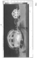
- FIG 1 shows a front view of a laser scanner 1 according to the invention with the structure explained at the beginning. Accordingly, a rotary head 4 with the measuring optics is mounted on a carrier 14 carrying a housing 2 of the laser scanner 1. The rotary head 4 is rotatable about a horizontal axis C (view according to Figure 1 ). The carrier with the housing 2 and the rotating head 4 can be pivoted about a vertical axis of rotation A.
- the device for recording thermography data is also mounted on the carrier 14.
- this is an infrared camera 6 (thermography camera) which is mounted on a platform 8 so as to be pivotable about an axis B, which in turn is attached to the carrier 14.
- the carrier 14 with the housing 2, the rotary head 4 and the infrared camera 6 can be pivoted step by step around the axis of rotation A.
- This step-by-step pivoting is in Figure 2 This means that during a measurement process for collecting the thermography data, the laser scanner 1, more precisely the carrier 14 with the housing 2 and the rotating head 4, is rotated to Figure 2
- the axis of rotation A (see arrow direction) is perpendicular to the plane of the drawing.
- the pivoting can take place in both directions.
- the viewing direction of the infrared camera 6 is adjusted according to Figure 3 to the vertical position perpendicular to the drawing plane ( Figure 3 ) axis B is adjusted - this step-by-step adjustment/pivoting is in Figure 3 shown with an arrow. This adjustment can also be made in both directions.
- the axis B runs transversely to the axis A, with both axes being offset from each other.
- the step-by-step pivoting of the infrared camera 6 and the actual laser scanner 1 is preferably controlled via the control of the laser scanner 1.
- the motorized thermographic camera/infrared camera 6 automatically generates a spherical 360° panoramic image, which is supplemented with the 3D scan data or assigned to it in order to obtain a thermal image, in particular a thermal panoramic image.
- a thermal image in particular a thermal panoramic image.
- each measuring point of a 3D scan can be assigned a temperature or information from which the temperature can be derived.
- smaller sphere sections can also be scanned and recorded thermographically.
- the footprint required by the laser scanner 1 and its geometric dimensions already result in a small, ground-level sphere section that cannot be scanned/detected thermographically. To avoid this, other storage concepts for the rotating head and/or the thermographic camera are conceivable.
- the platform 8 described above is provided, which accommodates a commercially available infrared camera 6 and moves it in the vertical direction ( Figure 3 ).
- This platform 8 with the infrared camera 6 is attached to the actual laser scanner 1 (carrier 14). Due to the additional horizontal rotation of the laser scanner 1 ( Figure 2 ) any viewing direction can then be automatically approached.
- the 3D scanner rotates step by step around the rotation axis A ( Figure 2 ).
- the infrared camera 6 takes a single image.
- the infrared camera 6 is moved vertically one step upwards over the platform 8 around the axis B ( Figure 3 ).
- the 3D scanner 1 rotates again around its Rotation axis A and the infrared camera 6 take a single image at each intermediate position.
- thermographic images are repeated until the zenith above the scanner or laser scanner 1 is covered with thermographic images.
- the viewing direction can be changed via the platform 8 in a first angular position of the housing 2, so that a vertical measurement is carried out first.
- the laser scanner 1 can then be swiveled one step around the axis A and the vertical measurement repeated. This process is then repeated accordingly until the entire room has been measured or its thermographic data has been recorded.
- Both the platform 8 and the infrared camera 6 are connected to the control of the laser scanner 1 via cables or the like. This ensures both the power supply and the communication via the central control of the laser scanner 1.
- the entire recording process, including the necessary control of the infrared camera 6 and the motorized platform 8, is carried out autonomously by the laser scanner 1.
- each camera lens system is individually adjusted and calibrated in the factory. This is done using calibration methods according to the invention, which must be adapted to the requirements of the thermographic camera 6, in particular.
- the lens of the infrared camera 6, or thermography camera 6, is adjusted to the hyperfocal distance in order to be able to cover as large a distance range as possible with the thermography camera 6.
- a thermographically clearly visible test object is preferably used, for example a special "Siemens star", which is visible to the thermography camera 6 so that it can be optimally focused.
- thermographic camera 6 For calibrate the internal calibration parameters of the thermographic camera 6, for example the radial distortion, the principal image point, etc., a special calibration object, preferably a checkerboard pattern, is used, which is also thermographically visible. By evaluating this pattern, the internal parameters mentioned can be determined using standard algorithms.
- thermographic camera 6 For external calibration (shifting/rotating the thermographic camera 6 relative to the coordinate system of the laser scanner 1), special target plates are used according to the invention, the centers of which must be visible in both the thermal image and the 3D image data. The centers are then determined in both data sets (thermographic data, 3D scan data) using special algorithms and the required transformations (external calibration) are determined from their offsets.
- the calibrations mentioned are carried out automatically via the control or control unit (not shown) of the laser scanner 1.
- thermographic camera 6 As soon as all optical and geometric parameters of the thermographic camera 6 have been determined by means of such a calibration, the individual images recorded can be rectified and calculated/merged to form a panoramic image.
- the entire recording process (swivelling around the rotation axis A and swivelling around the axis B), for example, around 32 images are collected, which contain the thermal radiation of the recorded objects in each pixel of the 3D scan. The temperature in each pixel can then be determined using a material-dependent emissivity.
- This thermal or thermography data can then be linked to the 3D data, which is preferably done partially transparently to make edges and details more visible.
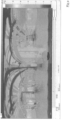
- the Figure 4 shows an example of such a finished thermal image panoramic image in a user interface of the device for assigning the Thermography data on pixels of the 3D scan. Shown is a machine room with pumps, containers, pipes and control cabinets. On the right in Figure 4 A temperature/color scale is shown, which allows the user to estimate the temperature of individual areas of the thermal image panorama.
- the interface offers the user support in analyzing thermal image panoramas and 3D views of point clouds with associated thermography data.
- the interface outputs the lowest and highest temperature in the thermal image panorama or in the 3D scan, displays the temperature below the cursor moved by the user, selects the degree of transparency of the thermography data, limits the display to a desired temperature interval, or switches between the thermal image panorama and the 3D view of the scanned point cloud with associated thermography data.
- FIG 5 On the right is a section of the finished thermal image panorama according to Figure 4 shown.
- Figure 5 On the left one of several possible 3D views of the scanned point cloud with associated thermography data is shown, which can be selected by the user.
- the thermography data comes from the finished thermal image panorama.
- the laser scanner 1 In the 3D view, the laser scanner 1 can be seen as a cuboid.
- Top right shows an overview of locations 12 of the laser scanner 1 during the scanning process.
- FIG 6 shows an example of a finished thermal image panorama of a house front (left in Figure 6 ) to analyse their thermal insulation.
- reddish coloured areas show a comparatively high temperature and poor thermal insulation.
- the facade of the house probably has a structural inhomogeneity 10.
- the high-resolution pixels of the 3D point cloud show no edges or other contours.
- the thermographic data indicate that the radiation behaviour of the facade has changed here. From the shape of the inhomogeneity 10, it can be assumed that an opening in the facade, for example a door, has been bricked up and plastered so that it is invisible to the human eye.
- there is an area with an absolutely homogeneous colour gradient which is the sky. To make the panoramic image easier to understand, the sky is in Figure 6 isolated and colored dark red.
- FIGs 8 and 9 show various 3D views of several point clouds calculated with associated thermography data for the analysis of the thermal insulation of a settlement.
- Figure 8 the direction of the Figure 9 to the settlement and vice versa in Figure 9 the direction of the Figure 8 on the settlement as an arrow.
- Areas that are transparent to the viewer are conspicuous. Examples include some of the roofs of the houses. Here, too, these are areas that are shaded during the scanning/capturing process and therefore cannot contain any pixels or thermography data.
- the laser scanner 1 was set up at various locations 12 for the scanning/capturing process. In Figure 8 Due to the selected view, only one of the locations 12 can be recognized. At each location 12, the area that cannot be scanned/detected by the laser scanner 1 is visible as a circular blue area with a gray border.
- thermographic camera A laser scanner equipped with a thermographic camera is disclosed.
- thermographic data using such a laser scanner is disclosed.
Landscapes
- Physics & Mathematics (AREA)
- Engineering & Computer Science (AREA)
- General Physics & Mathematics (AREA)
- Radar, Positioning & Navigation (AREA)
- Remote Sensing (AREA)
- Spectroscopy & Molecular Physics (AREA)
- Computer Networks & Wireless Communication (AREA)
- Electromagnetism (AREA)
- Human Computer Interaction (AREA)
- Radiation Pyrometers (AREA)
- Investigating Or Analyzing Materials Using Thermal Means (AREA)
- Length Measuring Devices By Optical Means (AREA)
Applications Claiming Priority (3)
| Application Number | Priority Date | Filing Date | Title |
|---|---|---|---|
| DE102014105113 | 2014-04-10 | ||
| DE102014109432.8A DE102014109432B4 (de) | 2014-04-10 | 2014-07-07 | Laserscanner und Verfahren |
| PCT/EP2015/057890 WO2015155354A1 (de) | 2014-04-10 | 2015-04-10 | Laserscanner und verfahren |
Publications (3)
| Publication Number | Publication Date |
|---|---|
| EP3129805A1 EP3129805A1 (de) | 2017-02-15 |
| EP3129805B1 true EP3129805B1 (de) | 2024-08-14 |
| EP3129805C0 EP3129805C0 (de) | 2024-08-14 |
Family
ID=54193088
Family Applications (1)
| Application Number | Title | Priority Date | Filing Date |
|---|---|---|---|
| EP15716769.3A Active EP3129805B1 (de) | 2014-04-10 | 2015-04-10 | Laserscanner und verfahren |
Country Status (5)
| Country | Link |
|---|---|
| US (1) | US10365369B2 (pl) |
| EP (1) | EP3129805B1 (pl) |
| DE (1) | DE102014109432B4 (pl) |
| PL (1) | PL3129805T3 (pl) |
| WO (1) | WO2015155354A1 (pl) |
Families Citing this family (10)
| Publication number | Priority date | Publication date | Assignee | Title |
|---|---|---|---|---|
| CN105571549A (zh) * | 2015-12-10 | 2016-05-11 | 南京诺威尔光电系统有限公司 | 一种柱面涂层热波成像无损检测方法 |
| CN107543616B (zh) * | 2016-06-24 | 2019-08-20 | 丘国强 | 利用三维热成像的机器状况监测系统 |
| DE102016119155A1 (de) | 2016-09-15 | 2018-03-15 | Zoller + Fröhlich GmbH | Laserscanner |
| CN106782032B (zh) * | 2016-12-27 | 2019-02-12 | 中国船舶重工集团公司第七0七研究所 | 一种面向纸海图作业的激光振镜跨区域指示方法 |
| CN107796518B (zh) * | 2017-09-22 | 2019-08-09 | 上海卫星工程研究所 | 线阵扫描相机对复杂地球背景成像试验方法 |
| JP6921036B2 (ja) * | 2018-05-28 | 2021-08-18 | 三菱電機株式会社 | レーザ較正装置、その較正方法、及びレーザ較正装置を含む画像入力装置 |
| CN109185643B (zh) * | 2018-11-14 | 2020-07-10 | 福建江夏学院 | 一种精密旋转云台装置 |
| EP3671261A1 (en) * | 2018-12-21 | 2020-06-24 | Leica Geosystems AG | 3d surveillance system comprising lidar and multispectral imaging for object classification |
| WO2020255589A1 (ja) * | 2019-06-17 | 2020-12-24 | ソニー株式会社 | 情報処理装置、情報処理方法及びプログラム |
| DE102023104404A1 (de) * | 2023-02-23 | 2024-08-29 | Bayerische Motoren Werke Aktiengesellschaft | Erfassungsvorrichtung |
Family Cites Families (5)
| Publication number | Priority date | Publication date | Assignee | Title |
|---|---|---|---|---|
| DE202006005643U1 (de) | 2006-03-31 | 2006-07-06 | Faro Technologies Inc., Lake Mary | Vorrichtung zum dreidimensionalen Erfassen eines Raumbereichs |
| DE102009015921A1 (de) * | 2009-03-25 | 2010-09-30 | Faro Technologies, Inc., Lake Mary | Verfahren zum optischen Abtasten und Vermessen einer Umgebung |
| DE102011089629B4 (de) * | 2010-12-22 | 2022-08-04 | pmdtechnologies ag | Lichtlaufzeitkamera und Verfahren zum Betreiben einer solchen |
| DE102012105027B4 (de) * | 2011-06-09 | 2015-08-13 | Zoller & Fröhlich GmbH | Laserscanner und Verfahren zum Ansteuern eines Laserscanners |
| DE202013104715U1 (de) * | 2013-10-21 | 2015-01-22 | Sick Ag | Sensor mit um Drehachse beweglicher Abtasteinheit |
-
2014
- 2014-07-07 DE DE102014109432.8A patent/DE102014109432B4/de active Active
-
2015
- 2015-04-10 PL PL15716769.3T patent/PL3129805T3/pl unknown
- 2015-04-10 WO PCT/EP2015/057890 patent/WO2015155354A1/de not_active Ceased
- 2015-04-10 US US15/302,378 patent/US10365369B2/en active Active
- 2015-04-10 EP EP15716769.3A patent/EP3129805B1/de active Active
Also Published As
| Publication number | Publication date |
|---|---|
| US10365369B2 (en) | 2019-07-30 |
| US20170067995A1 (en) | 2017-03-09 |
| DE102014109432A1 (de) | 2015-10-15 |
| DE102014109432B4 (de) | 2021-02-11 |
| EP3129805A1 (de) | 2017-02-15 |
| PL3129805T3 (pl) | 2024-12-16 |
| EP3129805C0 (de) | 2024-08-14 |
| WO2015155354A1 (de) | 2015-10-15 |
Similar Documents
| Publication | Publication Date | Title |
|---|---|---|
| DE102014109432B4 (de) | Laserscanner und Verfahren | |
| DE10219054B4 (de) | Verfahren und Vorrichtung zur Bestimmung der räumlichen Koordinaten eines Gegenstandes | |
| EP1759166B1 (de) | Verfahren zur vermessung von gegenständen mit einer herkömmlichen digitalkamera | |
| CN109816680B (zh) | 一种农作物株高的高通量计算方法 | |
| DE102012003255B4 (de) | Vorrichtung zur berührungslosen Temperaturmessung und Temperaturmessverfahren | |
| EP3346230B1 (de) | Vorrichtung und verfahren zur erfassung einer drahtkrümmung | |
| EP3315907B1 (de) | Verfahren zur visuellen darstellung von scandaten | |
| DE102005010390A1 (de) | Transparentes Kamerakalibrierungswerkzeug zur Kamerakalibrierung und dessen Kalibrierungsverfahren | |
| DE112013004369T5 (de) | Laserscanner mit zusätzlicher Erfassungsvorrichtung | |
| DE102008048963B4 (de) | 3D-Geometrie-Erfassungsverfahren und -vorrichtung | |
| DE102017109039A1 (de) | Verfahren zur Kalibrierung einer Kamera und eines Laserscanners | |
| DE112007003553B4 (de) | Merkmalsdetektionsvorrichtung und -verfahren zum Messen von Objektabständen | |
| KR101806045B1 (ko) | 적외선 및 가시광 카메라의 실시간 이미지 합성 장치 및 그 제어 방법 | |
| CN105118055A (zh) | 摄影机定位修正标定方法及系统 | |
| DE202014010159U1 (de) | Mobiles Schnellbau-Visualisierungsstudio zur Generierung dreidimensionaler Abbilder von beweglichen Zielobjekten | |
| DE10341822A1 (de) | Verfahren und Anordnung zur photogrammetrischen Messbildaufnahme und -verarbeitung | |
| EP3742136A1 (de) | Verfahren und vorrichtung zum erzeugen eines dreidimensionalen thermogramms | |
| DE112018002883T5 (de) | Verfahren zur messung von geometrischen parametern und / oder mustserverformungen unter einfluss einer hochtemperatur und ein system zur durchführung des verfahrens | |
| DE102017100885B4 (de) | Verfahren und vorrichtung zum erzeugen und projizieren eines 3d-thermogramms samt daten zu den aufnahmebedingungen | |
| EP3064894B1 (de) | 3d-scanvorrichtung und verfahren zum bestimmen einer digitalen 3d-repräsentation einer person | |
| DE102013107597A1 (de) | Vermessungsverfahren für gebäudeöffnungen und gebäudeabschlussherstellverfahren sowie vorrichtungen zur durchführung derselben | |
| WO2012052244A2 (de) | Erfassung und darstellung texturierter drei-dimensionaler geometrien | |
| DE102012022045A1 (de) | Verfahren zur Bildaufbereitung und damit durchführbares Verfahren zur automatischen Objekterkennung sowie Beobachtungsvorrichtung und Verfahren zur hochgenauen Bahn-Verfolgung startender Raketen auf große Entfernungen | |
| DE102013208687A1 (de) | Vorrichtung und Verfahren zum Ermitteln einer Raumtemperatur | |
| EP2899973A1 (de) | Verfahren und System zur thermografischen 3D-Erfassung von dreidimensionalen Objekten |
Legal Events
| Date | Code | Title | Description |
|---|---|---|---|
| STAA | Information on the status of an ep patent application or granted ep patent |
Free format text: STATUS: THE INTERNATIONAL PUBLICATION HAS BEEN MADE |
|
| PUAI | Public reference made under article 153(3) epc to a published international application that has entered the european phase |
Free format text: ORIGINAL CODE: 0009012 |
|
| STAA | Information on the status of an ep patent application or granted ep patent |
Free format text: STATUS: REQUEST FOR EXAMINATION WAS MADE |
|
| 17P | Request for examination filed |
Effective date: 20161110 |
|
| AK | Designated contracting states |
Kind code of ref document: A1 Designated state(s): AL AT BE BG CH CY CZ DE DK EE ES FI FR GB GR HR HU IE IS IT LI LT LU LV MC MK MT NL NO PL PT RO RS SE SI SK SM TR |
|
| AX | Request for extension of the european patent |
Extension state: BA ME |
|
| DAV | Request for validation of the european patent (deleted) | ||
| DAX | Request for extension of the european patent (deleted) | ||
| STAA | Information on the status of an ep patent application or granted ep patent |
Free format text: STATUS: EXAMINATION IS IN PROGRESS |
|
| 17Q | First examination report despatched |
Effective date: 20190424 |
|
| GRAP | Despatch of communication of intention to grant a patent |
Free format text: ORIGINAL CODE: EPIDOSNIGR1 |
|
| STAA | Information on the status of an ep patent application or granted ep patent |
Free format text: STATUS: GRANT OF PATENT IS INTENDED |
|
| RIC1 | Information provided on ipc code assigned before grant |
Ipc: G01J 5/07 20220101ALI20231002BHEP Ipc: G01J 5/04 20060101ALI20231002BHEP Ipc: G01J 5/48 20060101ALI20231002BHEP Ipc: G01J 5/02 20060101ALI20231002BHEP Ipc: G01J 5/08 20060101ALI20231002BHEP Ipc: G01S 17/86 20200101ALI20231002BHEP Ipc: G01S 17/02 20060101ALI20231002BHEP Ipc: G01S 17/42 20060101ALI20231002BHEP Ipc: G01S 7/481 20060101ALI20231002BHEP Ipc: G01S 7/497 20060101ALI20231002BHEP Ipc: G01S 17/89 20060101AFI20231002BHEP |
|
| INTG | Intention to grant announced |
Effective date: 20231023 |
|
| GRAJ | Information related to disapproval of communication of intention to grant by the applicant or resumption of examination proceedings by the epo deleted |
Free format text: ORIGINAL CODE: EPIDOSDIGR1 |
|
| STAA | Information on the status of an ep patent application or granted ep patent |
Free format text: STATUS: EXAMINATION IS IN PROGRESS |
|
| GRAP | Despatch of communication of intention to grant a patent |
Free format text: ORIGINAL CODE: EPIDOSNIGR1 |
|
| STAA | Information on the status of an ep patent application or granted ep patent |
Free format text: STATUS: GRANT OF PATENT IS INTENDED |
|
| INTC | Intention to grant announced (deleted) | ||
| INTG | Intention to grant announced |
Effective date: 20240314 |
|
| GRAS | Grant fee paid |
Free format text: ORIGINAL CODE: EPIDOSNIGR3 |
|
| GRAA | (expected) grant |
Free format text: ORIGINAL CODE: 0009210 |
|
| STAA | Information on the status of an ep patent application or granted ep patent |
Free format text: STATUS: THE PATENT HAS BEEN GRANTED |
|
| AK | Designated contracting states |
Kind code of ref document: B1 Designated state(s): AL AT BE BG CH CY CZ DE DK EE ES FI FR GB GR HR HU IE IS IT LI LT LU LV MC MK MT NL NO PL PT RO RS SE SI SK SM TR |
|
| REG | Reference to a national code |
Ref country code: GB Ref legal event code: FG4D Free format text: NOT ENGLISH |
|
| REG | Reference to a national code |
Ref country code: CH Ref legal event code: EP |
|
| REG | Reference to a national code |
Ref country code: DE Ref legal event code: R096 Ref document number: 502015016917 Country of ref document: DE |
|
| REG | Reference to a national code |
Ref country code: IE Ref legal event code: FG4D Free format text: LANGUAGE OF EP DOCUMENT: GERMAN |
|
| U01 | Request for unitary effect filed |
Effective date: 20240905 |
|
| U07 | Unitary effect registered |
Designated state(s): AT BE BG DE DK EE FI FR IT LT LU LV MT NL PT RO SE SI Effective date: 20240923 |
|
| PG25 | Lapsed in a contracting state [announced via postgrant information from national office to epo] |
Ref country code: NO Free format text: LAPSE BECAUSE OF FAILURE TO SUBMIT A TRANSLATION OF THE DESCRIPTION OR TO PAY THE FEE WITHIN THE PRESCRIBED TIME-LIMIT Effective date: 20241114 |
|
| PG25 | Lapsed in a contracting state [announced via postgrant information from national office to epo] |
Ref country code: GR Free format text: LAPSE BECAUSE OF FAILURE TO SUBMIT A TRANSLATION OF THE DESCRIPTION OR TO PAY THE FEE WITHIN THE PRESCRIBED TIME-LIMIT Effective date: 20241115 |
|
| PG25 | Lapsed in a contracting state [announced via postgrant information from national office to epo] |
Ref country code: IS Free format text: LAPSE BECAUSE OF FAILURE TO SUBMIT A TRANSLATION OF THE DESCRIPTION OR TO PAY THE FEE WITHIN THE PRESCRIBED TIME-LIMIT Effective date: 20241214 |
|
| PG25 | Lapsed in a contracting state [announced via postgrant information from national office to epo] |
Ref country code: HR Free format text: LAPSE BECAUSE OF FAILURE TO SUBMIT A TRANSLATION OF THE DESCRIPTION OR TO PAY THE FEE WITHIN THE PRESCRIBED TIME-LIMIT Effective date: 20240814 |
|
| PG25 | Lapsed in a contracting state [announced via postgrant information from national office to epo] |
Ref country code: ES Free format text: LAPSE BECAUSE OF FAILURE TO SUBMIT A TRANSLATION OF THE DESCRIPTION OR TO PAY THE FEE WITHIN THE PRESCRIBED TIME-LIMIT Effective date: 20240814 Ref country code: RS Free format text: LAPSE BECAUSE OF FAILURE TO SUBMIT A TRANSLATION OF THE DESCRIPTION OR TO PAY THE FEE WITHIN THE PRESCRIBED TIME-LIMIT Effective date: 20241114 |
|
| PG25 | Lapsed in a contracting state [announced via postgrant information from national office to epo] |
Ref country code: RS Free format text: LAPSE BECAUSE OF FAILURE TO SUBMIT A TRANSLATION OF THE DESCRIPTION OR TO PAY THE FEE WITHIN THE PRESCRIBED TIME-LIMIT Effective date: 20241114 Ref country code: NO Free format text: LAPSE BECAUSE OF FAILURE TO SUBMIT A TRANSLATION OF THE DESCRIPTION OR TO PAY THE FEE WITHIN THE PRESCRIBED TIME-LIMIT Effective date: 20241114 Ref country code: IS Free format text: LAPSE BECAUSE OF FAILURE TO SUBMIT A TRANSLATION OF THE DESCRIPTION OR TO PAY THE FEE WITHIN THE PRESCRIBED TIME-LIMIT Effective date: 20241214 Ref country code: HR Free format text: LAPSE BECAUSE OF FAILURE TO SUBMIT A TRANSLATION OF THE DESCRIPTION OR TO PAY THE FEE WITHIN THE PRESCRIBED TIME-LIMIT Effective date: 20240814 Ref country code: GR Free format text: LAPSE BECAUSE OF FAILURE TO SUBMIT A TRANSLATION OF THE DESCRIPTION OR TO PAY THE FEE WITHIN THE PRESCRIBED TIME-LIMIT Effective date: 20241115 Ref country code: ES Free format text: LAPSE BECAUSE OF FAILURE TO SUBMIT A TRANSLATION OF THE DESCRIPTION OR TO PAY THE FEE WITHIN THE PRESCRIBED TIME-LIMIT Effective date: 20240814 |
|
| PG25 | Lapsed in a contracting state [announced via postgrant information from national office to epo] |
Ref country code: SM Free format text: LAPSE BECAUSE OF FAILURE TO SUBMIT A TRANSLATION OF THE DESCRIPTION OR TO PAY THE FEE WITHIN THE PRESCRIBED TIME-LIMIT Effective date: 20240814 |
|
| PG25 | Lapsed in a contracting state [announced via postgrant information from national office to epo] |
Ref country code: CZ Free format text: LAPSE BECAUSE OF FAILURE TO SUBMIT A TRANSLATION OF THE DESCRIPTION OR TO PAY THE FEE WITHIN THE PRESCRIBED TIME-LIMIT Effective date: 20240814 |
|
| PG25 | Lapsed in a contracting state [announced via postgrant information from national office to epo] |
Ref country code: SK Free format text: LAPSE BECAUSE OF FAILURE TO SUBMIT A TRANSLATION OF THE DESCRIPTION OR TO PAY THE FEE WITHIN THE PRESCRIBED TIME-LIMIT Effective date: 20240814 |
|
| U20 | Renewal fee for the european patent with unitary effect paid |
Year of fee payment: 11 Effective date: 20250409 |
|
| PLBE | No opposition filed within time limit |
Free format text: ORIGINAL CODE: 0009261 |
|
| STAA | Information on the status of an ep patent application or granted ep patent |
Free format text: STATUS: NO OPPOSITION FILED WITHIN TIME LIMIT |
|
| 26N | No opposition filed |
Effective date: 20250515 |
|
| PGFP | Annual fee paid to national office [announced via postgrant information from national office to epo] |
Ref country code: CH Payment date: 20250501 Year of fee payment: 11 |
|
| PGFP | Annual fee paid to national office [announced via postgrant information from national office to epo] |
Ref country code: TR Payment date: 20250404 Year of fee payment: 11 |
|
| PG25 | Lapsed in a contracting state [announced via postgrant information from national office to epo] |
Ref country code: MC Free format text: LAPSE BECAUSE OF FAILURE TO SUBMIT A TRANSLATION OF THE DESCRIPTION OR TO PAY THE FEE WITHIN THE PRESCRIBED TIME-LIMIT Effective date: 20240814 |
|
| PGFP | Annual fee paid to national office [announced via postgrant information from national office to epo] |
Ref country code: GB Payment date: 20260327 Year of fee payment: 12 |
|
| PG25 | Lapsed in a contracting state [announced via postgrant information from national office to epo] |
Ref country code: IE Free format text: LAPSE BECAUSE OF NON-PAYMENT OF DUE FEES Effective date: 20250410 |
|
| PGFP | Annual fee paid to national office [announced via postgrant information from national office to epo] |
Ref country code: PL Payment date: 20260311 Year of fee payment: 12 |
|
| REG | Reference to a national code |
Ref country code: CH Ref legal event code: U11 Free format text: ST27 STATUS EVENT CODE: U-0-0-U10-U11 (AS PROVIDED BY THE NATIONAL OFFICE) Effective date: 20260501 |
|
| U20 | Renewal fee for the european patent with unitary effect paid |
Year of fee payment: 12 Effective date: 20260331 |