EP3129596B1 - Method of protecting a component of a turbomachine from liquid droplets erosion, component and turbomachine - Google Patents
Method of protecting a component of a turbomachine from liquid droplets erosion, component and turbomachine Download PDFInfo
- Publication number
- EP3129596B1 EP3129596B1 EP15714219.1A EP15714219A EP3129596B1 EP 3129596 B1 EP3129596 B1 EP 3129596B1 EP 15714219 A EP15714219 A EP 15714219A EP 3129596 B1 EP3129596 B1 EP 3129596B1
- Authority
- EP
- European Patent Office
- Prior art keywords
- component
- materials
- protective layer
- covered
- turbomachine
- Prior art date
- Legal status (The legal status is an assumption and is not a legal conclusion. Google has not performed a legal analysis and makes no representation as to the accuracy of the status listed.)
- Active
Links
Images

Classifications
-
- F—MECHANICAL ENGINEERING; LIGHTING; HEATING; WEAPONS; BLASTING
- F01—MACHINES OR ENGINES IN GENERAL; ENGINE PLANTS IN GENERAL; STEAM ENGINES
- F01D—NON-POSITIVE DISPLACEMENT MACHINES OR ENGINES, e.g. STEAM TURBINES
- F01D5/00—Blades; Blade-carrying members; Heating, heat-insulating, cooling or antivibration means on the blades or the members
- F01D5/12—Blades
- F01D5/28—Selecting particular materials; Particular measures relating thereto; Measures against erosion or corrosion
-
- F—MECHANICAL ENGINEERING; LIGHTING; HEATING; WEAPONS; BLASTING
- F01—MACHINES OR ENGINES IN GENERAL; ENGINE PLANTS IN GENERAL; STEAM ENGINES
- F01D—NON-POSITIVE DISPLACEMENT MACHINES OR ENGINES, e.g. STEAM TURBINES
- F01D5/00—Blades; Blade-carrying members; Heating, heat-insulating, cooling or antivibration means on the blades or the members
- F01D5/12—Blades
- F01D5/28—Selecting particular materials; Particular measures relating thereto; Measures against erosion or corrosion
- F01D5/288—Protective coatings for blades
-
- F—MECHANICAL ENGINEERING; LIGHTING; HEATING; WEAPONS; BLASTING
- F01—MACHINES OR ENGINES IN GENERAL; ENGINE PLANTS IN GENERAL; STEAM ENGINES
- F01D—NON-POSITIVE DISPLACEMENT MACHINES OR ENGINES, e.g. STEAM TURBINES
- F01D5/00—Blades; Blade-carrying members; Heating, heat-insulating, cooling or antivibration means on the blades or the members
- F01D5/12—Blades
- F01D5/28—Selecting particular materials; Particular measures relating thereto; Measures against erosion or corrosion
- F01D5/286—Particular treatment of blades, e.g. to increase durability or resistance against corrosion or erosion
-
- F—MECHANICAL ENGINEERING; LIGHTING; HEATING; WEAPONS; BLASTING
- F04—POSITIVE - DISPLACEMENT MACHINES FOR LIQUIDS; PUMPS FOR LIQUIDS OR ELASTIC FLUIDS
- F04D—NON-POSITIVE-DISPLACEMENT PUMPS
- F04D17/00—Radial-flow pumps, e.g. centrifugal pumps; Helico-centrifugal pumps
- F04D17/08—Centrifugal pumps
- F04D17/10—Centrifugal pumps for compressing or evacuating
-
- F—MECHANICAL ENGINEERING; LIGHTING; HEATING; WEAPONS; BLASTING
- F04—POSITIVE - DISPLACEMENT MACHINES FOR LIQUIDS; PUMPS FOR LIQUIDS OR ELASTIC FLUIDS
- F04D—NON-POSITIVE-DISPLACEMENT PUMPS
- F04D29/00—Details, component parts, or accessories
- F04D29/02—Selection of particular materials
- F04D29/023—Selection of particular materials especially adapted for elastic fluid pumps
-
- F—MECHANICAL ENGINEERING; LIGHTING; HEATING; WEAPONS; BLASTING
- F04—POSITIVE - DISPLACEMENT MACHINES FOR LIQUIDS; PUMPS FOR LIQUIDS OR ELASTIC FLUIDS
- F04D—NON-POSITIVE-DISPLACEMENT PUMPS
- F04D29/00—Details, component parts, or accessories
- F04D29/40—Casings; Connections of working fluid
- F04D29/42—Casings; Connections of working fluid for radial or helico-centrifugal pumps
- F04D29/44—Fluid-guiding means, e.g. diffusers
- F04D29/441—Fluid-guiding means, e.g. diffusers especially adapted for elastic fluid pumps
- F04D29/444—Bladed diffusers
-
- F—MECHANICAL ENGINEERING; LIGHTING; HEATING; WEAPONS; BLASTING
- F05—INDEXING SCHEMES RELATING TO ENGINES OR PUMPS IN VARIOUS SUBCLASSES OF CLASSES F01-F04
- F05D—INDEXING SCHEME FOR ASPECTS RELATING TO NON-POSITIVE-DISPLACEMENT MACHINES OR ENGINES, GAS-TURBINES OR JET-PROPULSION PLANTS
- F05D2230/00—Manufacture
- F05D2230/90—Coating; Surface treatment
Definitions
- Embodiments of the subject matter disclosed herein relate to methods of protecting a component of a turbomachine from liquid droplets erosion, components of turbomachines protected according to such methods and turbomachines comprising such components.
- EP 2 312 018 A1 discloses a component for a rotary machine.
- WO 03/044374 A1 discloses a compressor.
- US 2009/123737 A1 discloses a solid particle erosion resistant surface.
- US7901799B2 discloses multilayer nitride-containing erosion resistant coatings.
- erosion hard materials are used while in order to protect against liquid droplets erosion tough materials are used.
- the present invention deals with liquid droplets erosion.
- the inventors have realized that solid particles erosion proceed in a uniform way; as it is shown in Fig.1 , the erosion rate is approximately constant.
- the Inventors have found that, surprisingly, by using a protective layer consisting of a plurality of sub-layers of different materials having high hardness and low fracture toughness, there is an initial "incubation period", but then erosion proceeds very slowly and approximately linearly - see Fig.4 ; according to a simplified description of the phenomenon, the various sub-layers are eroded slowly one after the other.
- each sub-layer is compact and is firmly connected to the sub-layer below; therefore, it is possible to cover a body with a thick protective layer; thickness of such layer may reach 70 microns and therefore its protection effect is relatively long.
- the inventors have though of using a protective layers consisting of a plurality of sub-layers of different materials having high hardness and low fracture toughness such layers in turbomachines, in particular in centrifugal compressors, in particular (but not only) for their closed centrifugal impellers.
- the preferred technology used for applying such layer is Physical Vapor Deposition, in short PVD, more specifically Cathodic Arc PVD, or Chemical Vapor Deposition, in short CVD.
- First exemplary embodiments relate to methods of protecting a component of a turbomachine from liquid droplets erosion, comprising covering at least one region of a component surface exposed to a flow of a fluid containing a liquid phase to be processed by the turbomachine with a protective layer; the protective layer comprises a plurality of adjacent sub-layers of different materials; the materials have high hardness in the range of 1000-3000 HV and low fracture toughness below 20 MPam 1/2 .
- the materials are two and are arranged in alternate position.
- the first material of the two materials is a stoichiometric nitride or carbide or boride of titanium or zirconium or chromium or tungsten or aluminum or vanadium.
- the second material of the two materials is a non-stoichiometric nitride or carbide or boride of titanium or zirconium or chromium or tungsten or aluminum or vanadium.
- Second exemplary embodiments relate to components of a centrifugal compressor having a surface exposed to a flow of a fluid containing a liquid phase to be compressed by the centrifugal compressor; at least one region of the surface is covered with a protective layer; the protective layer comprises a plurality of adjacent sub-layers of two materials in alternate position; the materials have high hardness in the range of 1000-3000 HV and low fracture toughness below 20 MPam 1/2 .
- Third exemplary embodiments relate to turbomachines comprising at least one component as set out above or wherein the methods as set out above have been applied.
- Fig.5 shows a schematic cross-section of an embodiment of a layer according to the present invention covering a surface of a component of a turbomachine; in this figure, reference S corresponds to the substrate, i.e. to the body of the component; there are four overlying sub-layers L1, L2, L3, L4 that have substantially the same width that constitute a protective layer.
- Sub-layers L1, L2, L3, L4 are of different materials, all of them having high hardness in the range of 1000-3000 HV and low fracture toughness below 20 MPam 1/2 .
- the materials of the sub-layers are selected from the group comprising nitrides, carbides and borides (preferably nitrides and carbides) of one or more substances; these substances are selected from the group comprising titanium, zirconium, chromium, tungsten, aluminum and vanadium (preferably titanium, chromium, tungsten and aluminum).
- the protective layer comprises a plurality of adjacent sub-layers of two materials in alternate position; a first material of the two materials and a second material of the two materials are a nitride, carbide or boride of titanium, zirconium, chromium, tungsten, aluminum or vanadium; examples of such material are TiN and TiAIN.
- a first material of the two materials and a second material of the two materials are a nitride, carbide or boride of titanium, zirconium, chromium, tungsten, aluminum or vanadium; examples of such material are TiN and TiAIN.
- sub-layers L1 and L3 are made of the first material and sub-layers L2 and L4 are made of the second material.
- sub-layers L1 and L3 are made of a compound in stoichiometric composition (in particular TiN), and sub-layers L2 and L4 are made of the same compound in non-stoichiometric composition (in particular TiN); these two materials have slightly different high hardness and slightly different low toughness.
- These sub-layers generate a protection that has low toughness, due to the non-stoichiometric composition, and high hardness, due to the stoichiometric composition.
- the widths of such sub-layers may be different or substantially equal and in the range from 0.1 microns to 5.0 microns, preferably in the range from 0.3 microns to 3.0 microns; if different, one may be e.g. 0.5 microns and the other e.g. 2.0 or 2.5 microns.
- the total number of sub-layers may vary from a minimum of 2 to a maximum of 30; more typical values are in the range 5-10.
- the total width of the protective layer may vary from a minimum of 10 microns to a maximum of 70 microns; more typical values are in the range 15-30 microns.
- a first very effective way to realize the covering of the component according to the present invention is by the technology known as “Chemical Vapor Deposition", in short CVD.
- a second very effective way to realize the covering of the component according to the present invention is by the technology known as "Physical Vapor Deposition", in short PVD, more specifically Cathodic Arc PVD.
- the Cathodic Arc PVD technology uses "targets" for realizing the deposition on the part to be covered; typically, the “targets” are located and/or shaped so that at least the targets see directly the region of the part to be covered by deposition.
- the rotation of the component during the PVD process may be advantageously used for reaching difficult regions (this will be more clear in the following); in this sense, it may be said that the "targets" are located and/or shaped so that at least the targets see indirectly the region of the part to be covered by deposition.
- the first sub-layer i.e. the sub-layer (L1 in Fig.5 ) bonded to substrate (S in Fig.5 ) could be completely different from other sub-layers in order to optimize the adhesion of the layer to the substrate; for example, it may be a thick Nickel "strike” made by electroless nickel plating, in short ENP, or by electroplating.
- Fig.6 shows a closed centrifugal impeller 60 (realized as a single piece) and two of its flow channels 61 and 62; points 63, 64 and 65 belong to the inlet zone and point 66, 67 and 68 belong to the out let zone; points 63 and 67 are on the hub; points 64 and 68 are on a blade; points 65 and 66 are on the shroud; point 63 is shown as a circle in order to highlight that Fig.5 is an enlarged view of this point; all these points 63, 64, 65, 66, 67 and 68 are exemplary points where it is particularly advantageous to have a LDE protection according the present invention; in this case, the substrate S, i.e. the body of the impeller, may be made for example of martensitic stainless steel or nickel-base alloy or cobalt-base alloy.
- the first impeller is usually the component of a compressor mostly affected by LDE.
- the protective layer according to the present invention is hard and fragile. Therefore, for example, when two pieces having such protective layer are put in contact to each other and then fixed to each other, it may be advantageous that their protective layers be not compressed; in this case, at least one and preferably both of the regions of contact are free from such protective layer.
- Fig.8 shows very schematically first possible Cathodic Arc PVD steps for manufacturing an embodiment of a closed centrifugal impeller 60 according to the present invention, more specifically the covering steps.
- the closed impeller 60 is arranged horizontally.
- T1 and T2 Two of the many "targets" are labeled T1 and T2; during the covering steps the impeller 60 is rotated about its symmetry axis.
- Fig.8 the arrows show the flow of material toward the component that is finally deposited on the component.
- the material flows into the flow paths of the impeller 60 and covers the outlet zone of the flow paths.
- the impeller 60 is rotated according to a first rotation sense ( Fig.8A ) and then to a second rotation sense ( Fig.8B ). Thanks to the rotation it is possible to cover also regions of the internal surface of the flow paths not directly seen by the targets T1 and T2.
- Fig.9 shows very schematically second possible Cathodic Arc PVD steps for manufacturing an embodiment of a closed centrifugal impeller 60 according to the present invention, more specifically the covering steps.
- T1, T2, T3, T4, T5 and T6 Six of the many "targets" are labeled T1, T2, T3, T4, T5 and T6.
Landscapes
- Engineering & Computer Science (AREA)
- Mechanical Engineering (AREA)
- General Engineering & Computer Science (AREA)
- Chemical & Material Sciences (AREA)
- Materials Engineering (AREA)
- Structures Of Non-Positive Displacement Pumps (AREA)
- Turbine Rotor Nozzle Sealing (AREA)
- Physical Vapour Deposition (AREA)
- Chemical Vapour Deposition (AREA)
Description
- Embodiments of the subject matter disclosed herein relate to methods of protecting a component of a turbomachine from liquid droplets erosion, components of turbomachines protected according to such methods and turbomachines comprising such components.
-
EP 2 312 018 A1 discloses a component for a rotary machine.WO 03/044374 A1 US 2009/123737 A1 discloses a solid particle erosion resistant surface.US7901799B2 discloses multilayer nitride-containing erosion resistant coatings. - In the field of turbomachines for oil & gas applications, two types of erosions affect the parts that get in contact with the flowing working fluid that is processed by the machine: solid particles erosion, in short SPE, and liquid droplets erosion, in short LDE. These two types of erosions are very different due to the different consistency of the elements hitting on the surfaces of such parts: hard bodies that erode the surface and bounce away after collision and soft bodies that hammer the surface and break into smaller soft bodies after collision.
- An erosion-protected part may be entirely made of a single material resistant to erosion or, more frequently, may consists of a body made of a material specifically adapted to the function of the part covered with a protective layer made of a material resistant to erosion.
- Typically, in order to protect against solid particles erosion hard materials are used while in order to protect against liquid droplets erosion tough materials are used.
- Very hard materials do not provide good results in case of hitting liquid droplets due to the fact that typically they are not tough enough to resist to hammering.
- Due to the increased performances requested in the field of turbomachines for oil & gas applications, there is always a need for improved solutions, including solutions to the problem of erosion. The present invention deals with liquid droplets erosion.
- The present invention is defined in the accompanying claims.
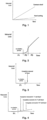
- The inventors have realized that solid particles erosion proceed in a uniform way; as it is shown in
Fig.1 , the erosion rate is approximately constant. - The Inventors have realized that liquid droplets erosion does not proceed in a uniform way. As it is shown in
Fig.2 , there is an initial period P1, so-called "incubation period", when there is basically no material loss; there is an intermediate period P2 when material loss increases very rapidly and more than linearly; there is a final period P3 when the erosion rate is approximately constant. When a protective layer is used, the layer is completely removed after some time that usually correspond to the sum of period P1 and part of period P2 depending on the width of the layer - seeFig.3 . - The Inventors have realized that it is very difficult to realize a thick (e.g. tens of microns) and compact protective layer of hard material firmly connected to the substrate. Usually, the thickness of such layer may only reach few microns and therefore its erosion protection effect is relatively short.
- The Inventors have found that, surprisingly, by using a protective layer consisting of a plurality of sub-layers of different materials having high hardness and low fracture toughness, there is an initial "incubation period", but then erosion proceeds very slowly and approximately linearly - see
Fig.4 ; according to a simplified description of the phenomenon, the various sub-layers are eroded slowly one after the other. - Furthermore, each sub-layer is compact and is firmly connected to the sub-layer below; therefore, it is possible to cover a body with a thick protective layer; thickness of such layer may reach 70 microns and therefore its protection effect is relatively long.
- It is worth mentioning that some coatings suppliers have recently started offering on the market protective layers consisting of a plurality of sub-layers of different materials having high hardness and low toughness for protection against erosion due to fine, medium and large particles.
- Anyway, a person skilled in the art could not have expected that such layers would have given good results for liquid droplets erosion due to the reasons set out above.
- The inventors have though of using a protective layers consisting of a plurality of sub-layers of different materials having high hardness and low fracture toughness such layers in turbomachines, in particular in centrifugal compressors, in particular (but not only) for their closed centrifugal impellers.
- The preferred technology used for applying such layer (to be precise each sub-layer of the layer) is Physical Vapor Deposition, in short PVD, more specifically Cathodic Arc PVD, or Chemical Vapor Deposition, in short CVD.
- With regard to closed centrifugal impellers, it is to be noted that the regions of the flow channels surfaces mostly affected by liquid droplets are the inlet zone and the outlet zone; PVD is a line-of-sight process, but, fortunately, for these zones, it is possible to locate and shape the "targets" so that they can be see directly or indirectly (i.e. through continuous rotation of the impeller) and be covered.
- First exemplary embodiments relate to methods of protecting a component of a turbomachine from liquid droplets erosion, comprising covering at least one region of a component surface exposed to a flow of a fluid containing a liquid phase to be processed by the turbomachine with a protective layer; the protective layer comprises a plurality of adjacent sub-layers of different materials; the materials have high hardness in the range of 1000-3000 HV and low fracture toughness below 20 MPam1/2.
- The materials are two and are arranged in alternate position.
- The first material of the two materials is a stoichiometric nitride or carbide or boride of titanium or zirconium or chromium or tungsten or aluminum or vanadium.
- The second material of the two materials is a non-stoichiometric nitride or carbide or boride of titanium or zirconium or chromium or tungsten or aluminum or vanadium.Second exemplary embodiments relate to components of a centrifugal compressor having a surface exposed to a flow of a fluid containing a liquid phase to be compressed by the centrifugal compressor; at least one region of the surface is covered with a protective layer; the protective layer comprises a plurality of adjacent sub-layers of two materials in alternate position; the materials have high hardness in the range of 1000-3000 HV and low fracture toughness below 20 MPam1/2.
- Third exemplary embodiments relate to turbomachines comprising at least one component as set out above or wherein the methods as set out above have been applied.
- The present invention will become more apparent from the following description of exemplary embodiments to be considered in conjunction with accompanying drawings wherein:
-
Fig. 1 shows a plot of material loss due to solid particles erosion against time for bulk material; -
Fig. 2 shows a plot of material loss due to liquid droplets erosion against time for bulk material; -
Fig. 3 shows a plot of material loss due to liquid droplets erosion against time for a layer of a single material; -
Fig. 4 shows a plot of material loss due to liquid droplets erosion against time for a layer made of a plurality of sub-layers according to an embodiment of the present invention; -
Fig.5 shows a schematic cross-section of an embodiment of a layer according to the present invention covering a surface of a component of a turbomachine; -
Fig.6 shows a schematic cross-section of an embodiment of a closed centrifugal impeller according to the present invention; -
Fig.7 shows a schematic cross-section view of a diaphragm according to the present invention (a centrifugal impeller is also shown); -
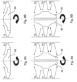
Fig.8 shows schematically first possible Cathodic Arc PVD steps for manufacturing an embodiment of a closed centrifugal impeller according to the present invention; and -
Fig.9 shows schematically second possible Cathodic Arc PVD steps for manufacturing an embodiment of a closed centrifugal impeller according to the present invention. - The following description of exemplary embodiments refer to the accompanying drawings. The same reference numbers in different drawings identify the same or similar elements. The following detailed description does not limit the invention. Instead, the scope of the invention is defined by the appended claims.
- Reference throughout the specification to "one embodiment" or "an embodiment" means that a particular feature, structure, or characteristic described in connection with an embodiment is included in at least one embodiment of the subject matter disclosed. Thus, the appearance of the phrases "in one embodiment" or "in an embodiment" in various places throughout the specification is not necessarily referring to the same embodiment. Further, the particular features, structures or characteristics may be combined in any suitable manner in one or more embodiments.
-
Fig.5 shows a schematic cross-section of an embodiment of a layer according to the present invention covering a surface of a component of a turbomachine; in this figure, reference S corresponds to the substrate, i.e. to the body of the component; there are four overlying sub-layers L1, L2, L3, L4 that have substantially the same width that constitute a protective layer. - Sub-layers L1, L2, L3, L4 are of different materials, all of them having high hardness in the range of 1000-3000 HV and low fracture toughness below 20 MPam1/2.
- The materials of the sub-layers are selected from the group comprising nitrides, carbides and borides (preferably nitrides and carbides) of one or more substances; these substances are selected from the group comprising titanium, zirconium, chromium, tungsten, aluminum and vanadium (preferably titanium, chromium, tungsten and aluminum).
- Typically, the protective layer comprises a plurality of adjacent sub-layers of two materials in alternate position; a first material of the two materials and a second material of the two materials are a nitride, carbide or boride of titanium, zirconium, chromium, tungsten, aluminum or vanadium; examples of such material are TiN and TiAIN. With reference to
Fig.5 , for example, sub-layers L1 and L3 are made of the first material and sub-layers L2 and L4 are made of the second material. - In the embodiment of
Fig.5 , sub-layers L1 and L3 are made of a compound in stoichiometric composition (in particular TiN), and sub-layers L2 and L4 are made of the same compound in non-stoichiometric composition (in particular TiN); these two materials have slightly different high hardness and slightly different low toughness. These sub-layers generate a protection that has low toughness, due to the non-stoichiometric composition, and high hardness, due to the stoichiometric composition. - The widths of such sub-layers may be different or substantially equal and in the range from 0.1 microns to 5.0 microns, preferably in the range from 0.3 microns to 3.0 microns; if different, one may be e.g. 0.5 microns and the other e.g. 2.0 or 2.5 microns.
- The total number of sub-layers may vary from a minimum of 2 to a maximum of 30; more typical values are in the range 5-10.
- The total width of the protective layer may vary from a minimum of 10 microns to a maximum of 70 microns; more typical values are in the range 15-30 microns.
- A first very effective way to realize the covering of the component according to the present invention is by the technology known as "Chemical Vapor Deposition", in short CVD.
- A second very effective way to realize the covering of the component according to the present invention is by the technology known as "Physical Vapor Deposition", in short PVD, more specifically Cathodic Arc PVD.
- As it is known, the Cathodic Arc PVD technology uses "targets" for realizing the deposition on the part to be covered; typically, the "targets" are located and/or shaped so that at least the targets see directly the region of the part to be covered by deposition.
- According to the present invention, as some regions of the surfaces of the components to be covered may be difficult to reach even if the location and shape of the targets are appropriately studied, the rotation of the component during the PVD process may be advantageously used for reaching difficult regions (this will be more clear in the following); in this sense, it may be said that the "targets" are located and/or shaped so that at least the targets see indirectly the region of the part to be covered by deposition.
- The first sub-layer, i.e. the sub-layer (L1 in
Fig.5 ) bonded to substrate (S inFig.5 ) could be completely different from other sub-layers in order to optimize the adhesion of the layer to the substrate; for example, it may be a thick Nickel "strike" made by electroless nickel plating, in short ENP, or by electroplating. - A layer according to the present invention may be applied to any part of a turbomachine, for example selected parts of centrifugal compressors, axial compressors and steam turbines that are likely to be exposed to liquid droplets collisions; in the case of compressors, liquid droplets are more likely in the first stage or stages; in the case of steam turbines, liquid droplets are more likely in the last stage or stages.
- One of the most useful applications of the protective layer according to the present invention is in centrifugal compressors.
- In centrifugal compressors, at least in some of them (i.e. those wherein the working fluid contains water that may be consist in droplets and/or turn into droplets), there are many components that may be covered entirely or, more frequently partially, with a protective layer according to the present invention.
- The component of the centrifugal compressor may be an impeller and the surface that is exposed to fluid flow containing a liquid phase and that is covered by the protective layer may correspond to the whole internal surfaces of the flow channels. In case of a closed impeller (i.e. realized as a single piece), the surface that is exposed to fluid flow containing a liquid phase and that is covered by the protective layer corresponds to the surfaces of only the inlet zone of the flow channels and/or the outlet zone of the flow channels, more in particular the surfaces of the blades.
Fig.6 shows a closed centrifugal impeller 60 (realized as a single piece) and two of itsflow channels points point point 63 is shown as a circle in order to highlight thatFig.5 is an enlarged view of this point; all thesepoints - It is to be noted that the first impeller is usually the component of a compressor mostly affected by LDE.
- The component of the centrifugal compressor may be a diaphragm; in this case, the surface that is exposed to fluid flow containing a liquid phase and that is covered by the protective layer may correspond to the whole internal surfaces of the return channels.
Fig.7 shows a diaphragm 70 (realized as a plurality of pieces that a fixed to each other for example by nuts and bolts) coupled to theimpeller 60 ofFig.6 and areturn channel 71;points point 73 is on the outside surface of an initial part of the initial U-shape portion of thereturn channel 71;point 74 is on the outside surface of an intermediate part of the initial U-shape portion of the return channel 71 (this point is located on the so-called "counter case"); points 75 and 76 are on a blade of thereturn channel 71 respectively at the begin and at the end. - The component of the centrifugal compressor may be an inlet guide vane, in short IGV, (i.e. the component located upstream the first compressor stage); in this case, the surface that is exposed to fluid flow containing a liquid phase and that is covered by the protective may correspond to all the surfaces of the component. This component is not shown in any figure.
- It is to be noted that, in order to reduce manufacturing costs, the covering according to the present invention may be done only on some portions of the components (those that are more affected by LDE); for example the blades of the return channels of the diaphragm or the vanes of the IGV.
- It is important to keep in mind that the protective layer according to the present invention is hard and fragile. Therefore, for example, when two pieces having such protective layer are put in contact to each other and then fixed to each other, it may be advantageous that their protective layers be not compressed; in this case, at least one and preferably both of the regions of contact are free from such protective layer.
-
Fig.8 shows very schematically first possible Cathodic Arc PVD steps for manufacturing an embodiment of a closedcentrifugal impeller 60 according to the present invention, more specifically the covering steps. - In
Fig.8 , theclosed impeller 60 is arranged horizontally. - In case of an open impeller, it is advantageous to place it so that the open side is facing down; in general, it is advantageous that any surface to be covered is facing down during the PVT or CVD process.
- Two of the many "targets" are labeled T1 and T2; during the covering steps the
impeller 60 is rotated about its symmetry axis. - In
Fig.8 , the arrows show the flow of material toward the component that is finally deposited on the component. The material flows into the flow paths of theimpeller 60 and covers the outlet zone of the flow paths. In order to improve the covering of the outlet zone of the flow paths, theimpeller 60 is rotated according to a first rotation sense (Fig.8A ) and then to a second rotation sense (Fig.8B ). Thanks to the rotation it is possible to cover also regions of the internal surface of the flow paths not directly seen by the targets T1 and T2. -
Fig.9 shows very schematically second possible Cathodic Arc PVD steps for manufacturing an embodiment of a closedcentrifugal impeller 60 according to the present invention, more specifically the covering steps. - In
Fig.9 , theclosed impeller 60 is arranged vertically; therefore, it is possible to arrange a secondclosed impeller 90; during the covering steps theclosed impeller 60 and theclosed impeller 90 are both rotated about an axis perpendicular to their symmetry axis. - Six of the many "targets" are labeled T1, T2, T3, T4, T5 and T6.
- In
Fig.9 , the arrows show the flow of material toward the component that is finally deposited on both the components. The material flows into the flow paths of theimpellers impellers Fig.9A ) and then to a second rotation sense (Fig.9B ). Thanks to the rotation it is possible to cover also regions of the internal surface of the flow paths not directly seen by the targets T1, T2, T3, T4, T5 and T6.
Claims (15)
- A method of protecting a component of a turbomachine from liquid droplets erosion, comprising covering at least one region (S) of a component surface exposed to a flow of a fluid containing a liquid phase to be processed by the turbomachine with a protective layer, wherein the protective layer comprises a plurality of alternate adjacent sub-layers (L1, L2, L3, L4) of two materials,wherein a first material of the two materials is a stoichiometric nitride or carbide or boride of titanium or zirconium or chromium or tungsten or aluminum or vanadium, and a second material of the two materials is a non-stoichiometric nitride or carbide or boride of titanium or zirconium or chromium or tungsten or aluminum or vanadium; andcharacterised in that said materials have high hardness in the range of 1000-3000 HV and low fracture toughness below 20 MPa m1/2.
- The method of claim 1, wherein said materials are Titanium Nitride (TiN).
- The method of claim 1 or 2, wherein said covering is carried out by a CVD technique.
- The method of claim 1 or 2, wherein said covering is carried out by a PVD technique, in particular by Cathodic Arc PVD.
- The method of claim 4, wherein "targets" for the Cathodic Arc PVD are located and/or shaped so that at least the targets see directly or indirectly parts of said at least one region of the component surface to be covered.
- A component (60, 70) of a centrifugal compressor having a surface exposed to a flow of a fluid containing a liquid phase to be compressed by the centrifugal compressor, wherein at least one region (S) of the surface is covered with a protective layer, wherein the protective layer comprises a plurality of alternate adjacent sub-layers (L1, L2, L3, L4) of two materials, whereina first material of the two materials is a stoichiometric nitride or carbide or boride of titanium or zirconium or chromium or tungsten or aluminum or vanadium, and a second material of the two materials is a non-stoichiometric nitride or carbide or boride of titanium or zirconium or chromium or tungsten or aluminum or vanadium; andcharacterised in that said materials have high hardness in the range of 1000-3000 HV and low fracture toughness below 20 MPa m1/2.
- The component of claim 6 being a diaphragm (70), wherein the surface exposed to fluid flow is covered by said protective layer entirely.
- The component of claim 6 being an open impeller, wherein the surface exposed to fluid flow is covered by said protective layer entirely.
- The component of claim 6 being a closed impeller (60), wherein the surface exposed to fluid flow is covered by said protective layer only at the inlet zone of the channels and/or at the outlet zone of the channels.
- The component of claim 6 being an inlet guide vane, wherein the surface exposed to fluid flow is covered by said protective layer entirely.
- A centrifugal compressor comprising at least one component according to any of claims from 6 to 10.
- The centrifugal compressor of claim 11, comprising a combination of components according to any of claims from 6 to 10.
- The centrifugal compressor of claim 11 or 12,
wherein the bulk material (S) of the or each component is martensitic stainless steel or nickel-base alloy or cobalt-base alloy. - An axial compressor comprising components according to claims 6-10, the components being blades of the first stage.
- A steam turbine comprising components according to claims 6-10, the components being blades of the last stage.
Applications Claiming Priority (2)
| Application Number | Priority Date | Filing Date | Title |
|---|---|---|---|
| ITCO20140010 | 2014-04-09 | ||
| PCT/EP2015/057336 WO2015155119A1 (en) | 2014-04-09 | 2015-04-02 | Method of protecting a component of a turbomachine from liquid droplets erosion, component and turbomachine |
Publications (2)
| Publication Number | Publication Date |
|---|---|
| EP3129596A1 EP3129596A1 (en) | 2017-02-15 |
| EP3129596B1 true EP3129596B1 (en) | 2023-12-13 |
Family
ID=50943381
Family Applications (1)
| Application Number | Title | Priority Date | Filing Date |
|---|---|---|---|
| EP15714219.1A Active EP3129596B1 (en) | 2014-04-09 | 2015-04-02 | Method of protecting a component of a turbomachine from liquid droplets erosion, component and turbomachine |
Country Status (6)
| Country | Link |
|---|---|
| US (1) | US10526903B2 (en) |
| EP (1) | EP3129596B1 (en) |
| JP (1) | JP6793039B2 (en) |
| CN (1) | CN106536860B (en) |
| RU (1) | RU2695245C2 (en) |
| WO (1) | WO2015155119A1 (en) |
Families Citing this family (6)
| Publication number | Priority date | Publication date | Assignee | Title |
|---|---|---|---|---|
| CN106122083B (en) * | 2016-08-26 | 2019-03-22 | 常州索拉尔熔盐泵阀科技有限公司 | Pump for liquid salts combination type blade wheel |
| SG11202010433PA (en) * | 2018-06-06 | 2020-11-27 | Ihi Corp | Turbine impeller |
| KR102083417B1 (en) * | 2018-06-25 | 2020-05-22 | 두산중공업 주식회사 | Composite coating layer having excellent erosion resistance and turbine component comprising the same |
| CN109653965B (en) * | 2018-11-27 | 2019-12-20 | 中国航空制造技术研究院 | Composite material blade protection method |
| US12037923B2 (en) * | 2019-07-08 | 2024-07-16 | Pratt & Whitney Canada Corp. | Pulse-managed plasma method for coating on internal surfaces of workpieces |
| IT202300005895A1 (en) * | 2023-03-28 | 2024-09-28 | Nuovo Pignone Tecnologie Srl | MULTILAYER COATING FOR HIGHLY STRESSED METAL PARTS |
Citations (1)
| Publication number | Priority date | Publication date | Assignee | Title |
|---|---|---|---|---|
| US7901799B2 (en) * | 2006-10-02 | 2011-03-08 | Praxair S.T. Technology, Inc. | Multilayer nitride-containing coatings |
Family Cites Families (17)
| Publication number | Priority date | Publication date | Assignee | Title |
|---|---|---|---|---|
| US3951612A (en) * | 1974-11-12 | 1976-04-20 | Aerospace Materials Inc. | Erosion resistant coatings |
| JPS63255357A (en) * | 1987-04-09 | 1988-10-21 | Hitachi Ltd | Turbine rotor blades and their manufacturing method |
| US5275850A (en) * | 1988-04-20 | 1994-01-04 | Hitachi, Ltd. | Process for producing a magnetic disk having a metal containing hard carbon coating by plasma chemical vapor deposition under a negative self bias |
| US4904542A (en) * | 1988-10-11 | 1990-02-27 | Midwest Research Technologies, Inc. | Multi-layer wear resistant coatings |
| ATE134717T1 (en) | 1989-09-11 | 1996-03-15 | Praxair Technology Inc | MULTI-LAYER COATING OF A MATERIAL CONTAINING NITRIDE AND ITS PRODUCTION |
| US5714202A (en) * | 1995-06-07 | 1998-02-03 | Lemelson; Jerome H. | Synthetic diamond overlays for gas turbine engine parts having thermal barrier coatings |
| DE10026477A1 (en) * | 2000-05-27 | 2001-11-29 | Abb Patent Gmbh | Protective cover for metallic components |
| AU2002366009A1 (en) * | 2001-11-19 | 2003-06-10 | Alstom Technology Ltd | Compressor for gas turbines |
| US7247348B2 (en) * | 2004-02-25 | 2007-07-24 | Honeywell International, Inc. | Method for manufacturing a erosion preventative diamond-like coating for a turbine engine compressor blade |
| WO2007083361A1 (en) | 2006-01-18 | 2007-07-26 | Mitsubishi Heavy Industries, Ltd. | Surface treatment coating film with resistance to erosion by solid particle and rotary machine |
| FR2909998B1 (en) | 2006-12-18 | 2009-03-06 | Snecma Propulsion Solide Sa | PIECE OF CERAMIC MATRIX COMPOSITE MATERIAL CONTAINING SILICON, PROTECTED AGAINST CORROSION |
| DE102008013965A1 (en) * | 2008-03-12 | 2009-09-17 | Kennametal Inc. | Hard material coated body |
| JP5244495B2 (en) * | 2008-08-06 | 2013-07-24 | 三菱重工業株式会社 | Parts for rotating machinery |
| US20100226783A1 (en) | 2009-03-06 | 2010-09-09 | General Electric Company | Erosion and Corrosion Resistant Turbine Compressor Airfoil and Method of Making the Same |
| JP5285486B2 (en) * | 2009-03-30 | 2013-09-11 | 三菱重工業株式会社 | Thermal barrier coating material, thermal barrier coating, turbine component and gas turbine |
| US20100304181A1 (en) * | 2009-05-29 | 2010-12-02 | General Electric Company | Protective coatings which provide erosion resistance, and related articles and methods |
| EP2581468A1 (en) * | 2011-10-14 | 2013-04-17 | Siemens Aktiengesellschaft | Method for applying an anti-wear protective coating to a flow engine component |
-
2015
- 2015-04-02 CN CN201580018050.5A patent/CN106536860B/en active Active
- 2015-04-02 JP JP2016560588A patent/JP6793039B2/en active Active
- 2015-04-02 US US15/302,506 patent/US10526903B2/en active Active
- 2015-04-02 EP EP15714219.1A patent/EP3129596B1/en active Active
- 2015-04-02 RU RU2016138579A patent/RU2695245C2/en active
- 2015-04-02 WO PCT/EP2015/057336 patent/WO2015155119A1/en not_active Ceased
Patent Citations (1)
| Publication number | Priority date | Publication date | Assignee | Title |
|---|---|---|---|---|
| US7901799B2 (en) * | 2006-10-02 | 2011-03-08 | Praxair S.T. Technology, Inc. | Multilayer nitride-containing coatings |
Also Published As
| Publication number | Publication date |
|---|---|
| RU2016138579A3 (en) | 2018-10-09 |
| RU2695245C2 (en) | 2019-07-22 |
| EP3129596A1 (en) | 2017-02-15 |
| US10526903B2 (en) | 2020-01-07 |
| WO2015155119A1 (en) | 2015-10-15 |
| US20170051616A1 (en) | 2017-02-23 |
| RU2016138579A (en) | 2018-05-10 |
| JP6793039B2 (en) | 2020-12-02 |
| CN106536860B (en) | 2019-01-11 |
| CN106536860A (en) | 2017-03-22 |
| JP2017521587A (en) | 2017-08-03 |
Similar Documents
| Publication | Publication Date | Title |
|---|---|---|
| US10526903B2 (en) | Method of protecting a component of a turbomachine from liquid droplets erosion, component and turbomachine | |
| CA2734605C (en) | Erosion- and impact-resistant coatings | |
| US7927709B2 (en) | Wear-resistant coating and a component having a wear-resistant coating | |
| US8047775B2 (en) | Layer system for a component comprising a thermal barrier coating and metallic erosion-resistant layer, production process and method for operating a steam turbine | |
| EP1403397B1 (en) | Cobalt-based alloy for the coating of components subject to erosion by liquid | |
| US20160115797A1 (en) | Coated article and method for producing coating | |
| US7758968B2 (en) | Component with thermal barrier coating and erosion-resistant layer | |
| EP3480428B1 (en) | Abrasive airfoil tip and fabrication method thereof | |
| KR20140103066A (en) | Turbomachine component with an erosion and corrosion resistant coating system and method for manufacturing such a component | |
| WO2014143244A1 (en) | Coating system for improved erosion protection of the leading edge of an airfoil | |
| JP2008538399A5 (en) | ||
| EP2885518B1 (en) | Thermal barrier coating having outer layer | |
| US10294962B2 (en) | Turbine engine seal for high erosion environment | |
| US20170335697A1 (en) | Method of producing blades or blade arrangements of a turbomachine with erosion protection layers and correspondingly produced component | |
| EP3839096A1 (en) | Diffusion barrier to prevent super alloy depletion into nickel-cbn blade tip coating | |
| JPS63255357A (en) | Turbine rotor blades and their manufacturing method | |
| US12359573B2 (en) | Blade for a turbomachine including blade tip armor and an erosion protection layer, and method for manufacturing same | |
| JP2004232499A (en) | Turbine rotor blade and method for forming film thereon | |
| US9719360B2 (en) | Turbomachine component having a functional coating | |
| EP3839095A1 (en) | Barrier to prevent super alloy depletion into nickel-cbn blade tip coating | |
| US20150247413A1 (en) | Coated article and method for producing coating | |
| JPH10122117A (en) | Hydraulic machinery | |
| CN119507992A (en) | Impeller with nano-metal ceramic coating for erosion resistance and cavitation erosion resistance | |
| PL228956B1 (en) | Protective coating for the turbine engine compressor blades | |
| JP2010265493A (en) | Coating material, turbine member coating method using the same, and turbine member using the same |
Legal Events
| Date | Code | Title | Description |
|---|---|---|---|
| STAA | Information on the status of an ep patent application or granted ep patent |
Free format text: STATUS: THE INTERNATIONAL PUBLICATION HAS BEEN MADE |
|
| PUAI | Public reference made under article 153(3) epc to a published international application that has entered the european phase |
Free format text: ORIGINAL CODE: 0009012 |
|
| STAA | Information on the status of an ep patent application or granted ep patent |
Free format text: STATUS: REQUEST FOR EXAMINATION WAS MADE |
|
| 17P | Request for examination filed |
Effective date: 20161109 |
|
| AK | Designated contracting states |
Kind code of ref document: A1 Designated state(s): AL AT BE BG CH CY CZ DE DK EE ES FI FR GB GR HR HU IE IS IT LI LT LU LV MC MK MT NL NO PL PT RO RS SE SI SK SM TR |
|
| AX | Request for extension of the european patent |
Extension state: BA ME |
|
| DAV | Request for validation of the european patent (deleted) | ||
| DAX | Request for extension of the european patent (deleted) | ||
| STAA | Information on the status of an ep patent application or granted ep patent |
Free format text: STATUS: EXAMINATION IS IN PROGRESS |
|
| 17Q | First examination report despatched |
Effective date: 20200804 |
|
| RAP1 | Party data changed (applicant data changed or rights of an application transferred) |
Owner name: NUOVO PIGNONE TECNOLOGIE - S.R.L. |
|
| P01 | Opt-out of the competence of the unified patent court (upc) registered |
Effective date: 20230526 |
|
| GRAP | Despatch of communication of intention to grant a patent |
Free format text: ORIGINAL CODE: EPIDOSNIGR1 |
|
| STAA | Information on the status of an ep patent application or granted ep patent |
Free format text: STATUS: GRANT OF PATENT IS INTENDED |
|
| GRAS | Grant fee paid |
Free format text: ORIGINAL CODE: EPIDOSNIGR3 |
|
| INTG | Intention to grant announced |
Effective date: 20231002 |
|
| GRAA | (expected) grant |
Free format text: ORIGINAL CODE: 0009210 |
|
| STAA | Information on the status of an ep patent application or granted ep patent |
Free format text: STATUS: THE PATENT HAS BEEN GRANTED |
|
| AK | Designated contracting states |
Kind code of ref document: B1 Designated state(s): AL AT BE BG CH CY CZ DE DK EE ES FI FR GB GR HR HU IE IS IT LI LT LU LV MC MK MT NL NO PL PT RO RS SE SI SK SM TR |
|
| REG | Reference to a national code |
Ref country code: GB Ref legal event code: FG4D |
|
| REG | Reference to a national code |
Ref country code: CH Ref legal event code: EP |
|
| REG | Reference to a national code |
Ref country code: DE Ref legal event code: R096 Ref document number: 602015086910 Country of ref document: DE |
|
| REG | Reference to a national code |
Ref country code: IE Ref legal event code: FG4D |
|
| REG | Reference to a national code |
Ref country code: SE Ref legal event code: TRGR |
|
| PG25 | Lapsed in a contracting state [announced via postgrant information from national office to epo] |
Ref country code: GR Free format text: LAPSE BECAUSE OF FAILURE TO SUBMIT A TRANSLATION OF THE DESCRIPTION OR TO PAY THE FEE WITHIN THE PRESCRIBED TIME-LIMIT Effective date: 20240314 |
|
| REG | Reference to a national code |
Ref country code: LT Ref legal event code: MG9D |
|
| PG25 | Lapsed in a contracting state [announced via postgrant information from national office to epo] |
Ref country code: LT Free format text: LAPSE BECAUSE OF FAILURE TO SUBMIT A TRANSLATION OF THE DESCRIPTION OR TO PAY THE FEE WITHIN THE PRESCRIBED TIME-LIMIT Effective date: 20231213 |
|
| REG | Reference to a national code |
Ref country code: NL Ref legal event code: MP Effective date: 20231213 |
|
| PG25 | Lapsed in a contracting state [announced via postgrant information from national office to epo] |
Ref country code: ES Free format text: LAPSE BECAUSE OF FAILURE TO SUBMIT A TRANSLATION OF THE DESCRIPTION OR TO PAY THE FEE WITHIN THE PRESCRIBED TIME-LIMIT Effective date: 20231213 |
|
| PG25 | Lapsed in a contracting state [announced via postgrant information from national office to epo] |
Ref country code: LT Free format text: LAPSE BECAUSE OF FAILURE TO SUBMIT A TRANSLATION OF THE DESCRIPTION OR TO PAY THE FEE WITHIN THE PRESCRIBED TIME-LIMIT Effective date: 20231213 Ref country code: GR Free format text: LAPSE BECAUSE OF FAILURE TO SUBMIT A TRANSLATION OF THE DESCRIPTION OR TO PAY THE FEE WITHIN THE PRESCRIBED TIME-LIMIT Effective date: 20240314 Ref country code: ES Free format text: LAPSE BECAUSE OF FAILURE TO SUBMIT A TRANSLATION OF THE DESCRIPTION OR TO PAY THE FEE WITHIN THE PRESCRIBED TIME-LIMIT Effective date: 20231213 Ref country code: BG Free format text: LAPSE BECAUSE OF FAILURE TO SUBMIT A TRANSLATION OF THE DESCRIPTION OR TO PAY THE FEE WITHIN THE PRESCRIBED TIME-LIMIT Effective date: 20240313 |
|
| REG | Reference to a national code |
Ref country code: AT Ref legal event code: MK05 Ref document number: 1640601 Country of ref document: AT Kind code of ref document: T Effective date: 20231213 |
|
| PG25 | Lapsed in a contracting state [announced via postgrant information from national office to epo] |
Ref country code: NL Free format text: LAPSE BECAUSE OF FAILURE TO SUBMIT A TRANSLATION OF THE DESCRIPTION OR TO PAY THE FEE WITHIN THE PRESCRIBED TIME-LIMIT Effective date: 20231213 |
|
| PG25 | Lapsed in a contracting state [announced via postgrant information from national office to epo] |
Ref country code: RS Free format text: LAPSE BECAUSE OF FAILURE TO SUBMIT A TRANSLATION OF THE DESCRIPTION OR TO PAY THE FEE WITHIN THE PRESCRIBED TIME-LIMIT Effective date: 20231213 Ref country code: NL Free format text: LAPSE BECAUSE OF FAILURE TO SUBMIT A TRANSLATION OF THE DESCRIPTION OR TO PAY THE FEE WITHIN THE PRESCRIBED TIME-LIMIT Effective date: 20231213 Ref country code: LV Free format text: LAPSE BECAUSE OF FAILURE TO SUBMIT A TRANSLATION OF THE DESCRIPTION OR TO PAY THE FEE WITHIN THE PRESCRIBED TIME-LIMIT Effective date: 20231213 Ref country code: HR Free format text: LAPSE BECAUSE OF FAILURE TO SUBMIT A TRANSLATION OF THE DESCRIPTION OR TO PAY THE FEE WITHIN THE PRESCRIBED TIME-LIMIT Effective date: 20231213 |
|
| PG25 | Lapsed in a contracting state [announced via postgrant information from national office to epo] |
Ref country code: IS Free format text: LAPSE BECAUSE OF FAILURE TO SUBMIT A TRANSLATION OF THE DESCRIPTION OR TO PAY THE FEE WITHIN THE PRESCRIBED TIME-LIMIT Effective date: 20240413 |
|
| PG25 | Lapsed in a contracting state [announced via postgrant information from national office to epo] |
Ref country code: CZ Free format text: LAPSE BECAUSE OF FAILURE TO SUBMIT A TRANSLATION OF THE DESCRIPTION OR TO PAY THE FEE WITHIN THE PRESCRIBED TIME-LIMIT Effective date: 20231213 Ref country code: AT Free format text: LAPSE BECAUSE OF FAILURE TO SUBMIT A TRANSLATION OF THE DESCRIPTION OR TO PAY THE FEE WITHIN THE PRESCRIBED TIME-LIMIT Effective date: 20231213 |
|
| PG25 | Lapsed in a contracting state [announced via postgrant information from national office to epo] |
Ref country code: SK Free format text: LAPSE BECAUSE OF FAILURE TO SUBMIT A TRANSLATION OF THE DESCRIPTION OR TO PAY THE FEE WITHIN THE PRESCRIBED TIME-LIMIT Effective date: 20231213 |
|
| PG25 | Lapsed in a contracting state [announced via postgrant information from national office to epo] |
Ref country code: SM Free format text: LAPSE BECAUSE OF FAILURE TO SUBMIT A TRANSLATION OF THE DESCRIPTION OR TO PAY THE FEE WITHIN THE PRESCRIBED TIME-LIMIT Effective date: 20231213 Ref country code: SK Free format text: LAPSE BECAUSE OF FAILURE TO SUBMIT A TRANSLATION OF THE DESCRIPTION OR TO PAY THE FEE WITHIN THE PRESCRIBED TIME-LIMIT Effective date: 20231213 Ref country code: RO Free format text: LAPSE BECAUSE OF FAILURE TO SUBMIT A TRANSLATION OF THE DESCRIPTION OR TO PAY THE FEE WITHIN THE PRESCRIBED TIME-LIMIT Effective date: 20231213 Ref country code: IT Free format text: LAPSE BECAUSE OF FAILURE TO SUBMIT A TRANSLATION OF THE DESCRIPTION OR TO PAY THE FEE WITHIN THE PRESCRIBED TIME-LIMIT Effective date: 20231213 Ref country code: IS Free format text: LAPSE BECAUSE OF FAILURE TO SUBMIT A TRANSLATION OF THE DESCRIPTION OR TO PAY THE FEE WITHIN THE PRESCRIBED TIME-LIMIT Effective date: 20240413 Ref country code: EE Free format text: LAPSE BECAUSE OF FAILURE TO SUBMIT A TRANSLATION OF THE DESCRIPTION OR TO PAY THE FEE WITHIN THE PRESCRIBED TIME-LIMIT Effective date: 20231213 Ref country code: CZ Free format text: LAPSE BECAUSE OF FAILURE TO SUBMIT A TRANSLATION OF THE DESCRIPTION OR TO PAY THE FEE WITHIN THE PRESCRIBED TIME-LIMIT Effective date: 20231213 Ref country code: AT Free format text: LAPSE BECAUSE OF FAILURE TO SUBMIT A TRANSLATION OF THE DESCRIPTION OR TO PAY THE FEE WITHIN THE PRESCRIBED TIME-LIMIT Effective date: 20231213 |
|
| PG25 | Lapsed in a contracting state [announced via postgrant information from national office to epo] |
Ref country code: PT Free format text: LAPSE BECAUSE OF FAILURE TO SUBMIT A TRANSLATION OF THE DESCRIPTION OR TO PAY THE FEE WITHIN THE PRESCRIBED TIME-LIMIT Effective date: 20240415 Ref country code: PL Free format text: LAPSE BECAUSE OF FAILURE TO SUBMIT A TRANSLATION OF THE DESCRIPTION OR TO PAY THE FEE WITHIN THE PRESCRIBED TIME-LIMIT Effective date: 20231213 |
|
| PG25 | Lapsed in a contracting state [announced via postgrant information from national office to epo] |
Ref country code: PT Free format text: LAPSE BECAUSE OF FAILURE TO SUBMIT A TRANSLATION OF THE DESCRIPTION OR TO PAY THE FEE WITHIN THE PRESCRIBED TIME-LIMIT Effective date: 20240415 Ref country code: PL Free format text: LAPSE BECAUSE OF FAILURE TO SUBMIT A TRANSLATION OF THE DESCRIPTION OR TO PAY THE FEE WITHIN THE PRESCRIBED TIME-LIMIT Effective date: 20231213 |
|
| REG | Reference to a national code |
Ref country code: DE Ref legal event code: R097 Ref document number: 602015086910 Country of ref document: DE |
|
| PG25 | Lapsed in a contracting state [announced via postgrant information from national office to epo] |
Ref country code: DK Free format text: LAPSE BECAUSE OF FAILURE TO SUBMIT A TRANSLATION OF THE DESCRIPTION OR TO PAY THE FEE WITHIN THE PRESCRIBED TIME-LIMIT Effective date: 20231213 |
|
| PLBE | No opposition filed within time limit |
Free format text: ORIGINAL CODE: 0009261 |
|
| STAA | Information on the status of an ep patent application or granted ep patent |
Free format text: STATUS: NO OPPOSITION FILED WITHIN TIME LIMIT |
|
| PG25 | Lapsed in a contracting state [announced via postgrant information from national office to epo] |
Ref country code: SI Free format text: LAPSE BECAUSE OF FAILURE TO SUBMIT A TRANSLATION OF THE DESCRIPTION OR TO PAY THE FEE WITHIN THE PRESCRIBED TIME-LIMIT Effective date: 20231213 |
|
| PG25 | Lapsed in a contracting state [announced via postgrant information from national office to epo] |
Ref country code: SI Free format text: LAPSE BECAUSE OF FAILURE TO SUBMIT A TRANSLATION OF THE DESCRIPTION OR TO PAY THE FEE WITHIN THE PRESCRIBED TIME-LIMIT Effective date: 20231213 Ref country code: DK Free format text: LAPSE BECAUSE OF FAILURE TO SUBMIT A TRANSLATION OF THE DESCRIPTION OR TO PAY THE FEE WITHIN THE PRESCRIBED TIME-LIMIT Effective date: 20231213 |
|
| 26N | No opposition filed |
Effective date: 20240916 |
|
| PG25 | Lapsed in a contracting state [announced via postgrant information from national office to epo] |
Ref country code: MC Free format text: LAPSE BECAUSE OF FAILURE TO SUBMIT A TRANSLATION OF THE DESCRIPTION OR TO PAY THE FEE WITHIN THE PRESCRIBED TIME-LIMIT Effective date: 20231213 |
|
| PG25 | Lapsed in a contracting state [announced via postgrant information from national office to epo] |
Ref country code: MC Free format text: LAPSE BECAUSE OF FAILURE TO SUBMIT A TRANSLATION OF THE DESCRIPTION OR TO PAY THE FEE WITHIN THE PRESCRIBED TIME-LIMIT Effective date: 20231213 |
|
| PG25 | Lapsed in a contracting state [announced via postgrant information from national office to epo] |
Ref country code: LU Free format text: LAPSE BECAUSE OF NON-PAYMENT OF DUE FEES Effective date: 20240402 |
|
| REG | Reference to a national code |
Ref country code: BE Ref legal event code: MM Effective date: 20240430 |
|
| PG25 | Lapsed in a contracting state [announced via postgrant information from national office to epo] |
Ref country code: LU Free format text: LAPSE BECAUSE OF NON-PAYMENT OF DUE FEES Effective date: 20240402 |
|
| PG25 | Lapsed in a contracting state [announced via postgrant information from national office to epo] |
Ref country code: BE Free format text: LAPSE BECAUSE OF NON-PAYMENT OF DUE FEES Effective date: 20240430 |
|
| PG25 | Lapsed in a contracting state [announced via postgrant information from national office to epo] |
Ref country code: FR Free format text: LAPSE BECAUSE OF NON-PAYMENT OF DUE FEES Effective date: 20240430 |
|
| PG25 | Lapsed in a contracting state [announced via postgrant information from national office to epo] |
Ref country code: FR Free format text: LAPSE BECAUSE OF NON-PAYMENT OF DUE FEES Effective date: 20240430 Ref country code: BE Free format text: LAPSE BECAUSE OF NON-PAYMENT OF DUE FEES Effective date: 20240430 |
|
| PG25 | Lapsed in a contracting state [announced via postgrant information from national office to epo] |
Ref country code: IE Free format text: LAPSE BECAUSE OF NON-PAYMENT OF DUE FEES Effective date: 20240402 |
|
| PGFP | Annual fee paid to national office [announced via postgrant information from national office to epo] |
Ref country code: DE Payment date: 20250321 Year of fee payment: 11 |
|
| PGFP | Annual fee paid to national office [announced via postgrant information from national office to epo] |
Ref country code: CH Payment date: 20250501 Year of fee payment: 11 |
|
| PG25 | Lapsed in a contracting state [announced via postgrant information from national office to epo] |
Ref country code: CY Free format text: LAPSE BECAUSE OF FAILURE TO SUBMIT A TRANSLATION OF THE DESCRIPTION OR TO PAY THE FEE WITHIN THE PRESCRIBED TIME-LIMIT; INVALID AB INITIO Effective date: 20150402 |
|
| PG25 | Lapsed in a contracting state [announced via postgrant information from national office to epo] |
Ref country code: HU Free format text: LAPSE BECAUSE OF FAILURE TO SUBMIT A TRANSLATION OF THE DESCRIPTION OR TO PAY THE FEE WITHIN THE PRESCRIBED TIME-LIMIT; INVALID AB INITIO Effective date: 20150402 |
|
| PG25 | Lapsed in a contracting state [announced via postgrant information from national office to epo] |
Ref country code: FI Free format text: LAPSE BECAUSE OF FAILURE TO SUBMIT A TRANSLATION OF THE DESCRIPTION OR TO PAY THE FEE WITHIN THE PRESCRIBED TIME-LIMIT Effective date: 20231213 |
|
| PG25 | Lapsed in a contracting state [announced via postgrant information from national office to epo] |
Ref country code: TR Free format text: LAPSE BECAUSE OF FAILURE TO SUBMIT A TRANSLATION OF THE DESCRIPTION OR TO PAY THE FEE WITHIN THE PRESCRIBED TIME-LIMIT Effective date: 20231213 |
|
| PGFP | Annual fee paid to national office [announced via postgrant information from national office to epo] |
Ref country code: SE Payment date: 20260319 Year of fee payment: 12 |
|
| PGFP | Annual fee paid to national office [announced via postgrant information from national office to epo] |
Ref country code: GB Payment date: 20260319 Year of fee payment: 12 |
|
| PGFP | Annual fee paid to national office [announced via postgrant information from national office to epo] |
Ref country code: NO Payment date: 20260320 Year of fee payment: 12 |
|
| REG | Reference to a national code |
Ref country code: CH Ref legal event code: U11 Free format text: ST27 STATUS EVENT CODE: U-0-0-U10-U11 (AS PROVIDED BY THE NATIONAL OFFICE) Effective date: 20260501 |