EP3129220B1 - Aircraft body mounted energy absorbing rub strip - Google Patents
Aircraft body mounted energy absorbing rub strip Download PDFInfo
- Publication number
- EP3129220B1 EP3129220B1 EP15705109.5A EP15705109A EP3129220B1 EP 3129220 B1 EP3129220 B1 EP 3129220B1 EP 15705109 A EP15705109 A EP 15705109A EP 3129220 B1 EP3129220 B1 EP 3129220B1
- Authority
- EP
- European Patent Office
- Prior art keywords
- fuselage
- rub strip
- aircraft
- core material
- fairing
- Prior art date
- Legal status (The legal status is an assumption and is not a legal conclusion. Google has not performed a legal analysis and makes no representation as to the accuracy of the status listed.)
- Not-in-force
Links
Images


Classifications
-
- B—PERFORMING OPERATIONS; TRANSPORTING
- B32—LAYERED PRODUCTS
- B32B—LAYERED PRODUCTS, i.e. PRODUCTS BUILT-UP OF STRATA OF FLAT OR NON-FLAT, e.g. CELLULAR OR HONEYCOMB, FORM
- B32B15/00—Layered products comprising a layer of metal
- B32B15/01—Layered products comprising a layer of metal all layers being exclusively metallic
-
- B—PERFORMING OPERATIONS; TRANSPORTING
- B32—LAYERED PRODUCTS
- B32B—LAYERED PRODUCTS, i.e. PRODUCTS BUILT-UP OF STRATA OF FLAT OR NON-FLAT, e.g. CELLULAR OR HONEYCOMB, FORM
- B32B15/00—Layered products comprising a layer of metal
- B32B15/01—Layered products comprising a layer of metal all layers being exclusively metallic
- B32B15/013—Layered products comprising a layer of metal all layers being exclusively metallic one layer being formed of an iron alloy or steel, another layer being formed of a metal other than iron or aluminium
- B32B15/015—Layered products comprising a layer of metal all layers being exclusively metallic one layer being formed of an iron alloy or steel, another layer being formed of a metal other than iron or aluminium the said other metal being copper or nickel or an alloy thereof
-
- B—PERFORMING OPERATIONS; TRANSPORTING
- B32—LAYERED PRODUCTS
- B32B—LAYERED PRODUCTS, i.e. PRODUCTS BUILT-UP OF STRATA OF FLAT OR NON-FLAT, e.g. CELLULAR OR HONEYCOMB, FORM
- B32B3/00—Layered products comprising a layer with external or internal discontinuities or unevennesses, or a layer of non-planar shape; Layered products comprising a layer having particular features of form
- B32B3/10—Layered products comprising a layer with external or internal discontinuities or unevennesses, or a layer of non-planar shape; Layered products comprising a layer having particular features of form characterised by a discontinuous layer, i.e. formed of separate pieces of material
- B32B3/12—Layered products comprising a layer with external or internal discontinuities or unevennesses, or a layer of non-planar shape; Layered products comprising a layer having particular features of form characterised by a discontinuous layer, i.e. formed of separate pieces of material characterised by a layer of regularly- arranged cells, e.g. a honeycomb structure
-
- B—PERFORMING OPERATIONS; TRANSPORTING
- B64—AIRCRAFT; AVIATION; COSMONAUTICS
- B64C—AEROPLANES; HELICOPTERS
- B64C1/00—Fuselages; Constructional features common to fuselages, wings, stabilising surfaces or the like
- B64C1/06—Frames; Stringers; Longerons ; Fuselage sections
-
- F—MECHANICAL ENGINEERING; LIGHTING; HEATING; WEAPONS; BLASTING
- F16—ENGINEERING ELEMENTS AND UNITS; GENERAL MEASURES FOR PRODUCING AND MAINTAINING EFFECTIVE FUNCTIONING OF MACHINES OR INSTALLATIONS; THERMAL INSULATION IN GENERAL
- F16F—SPRINGS; SHOCK-ABSORBERS; MEANS FOR DAMPING VIBRATION
- F16F7/00—Vibration-dampers; Shock-absorbers
- F16F7/12—Vibration-dampers; Shock-absorbers using plastic deformation of members
-
- B—PERFORMING OPERATIONS; TRANSPORTING
- B32—LAYERED PRODUCTS
- B32B—LAYERED PRODUCTS, i.e. PRODUCTS BUILT-UP OF STRATA OF FLAT OR NON-FLAT, e.g. CELLULAR OR HONEYCOMB, FORM
- B32B2307/00—Properties of the layers or laminate
- B32B2307/50—Properties of the layers or laminate having particular mechanical properties
- B32B2307/558—Impact strength, toughness
-
- B—PERFORMING OPERATIONS; TRANSPORTING
- B32—LAYERED PRODUCTS
- B32B—LAYERED PRODUCTS, i.e. PRODUCTS BUILT-UP OF STRATA OF FLAT OR NON-FLAT, e.g. CELLULAR OR HONEYCOMB, FORM
- B32B2307/00—Properties of the layers or laminate
- B32B2307/70—Other properties
- B32B2307/72—Density
- B32B2307/722—Non-uniform density
-
- B—PERFORMING OPERATIONS; TRANSPORTING
- B32—LAYERED PRODUCTS
- B32B—LAYERED PRODUCTS, i.e. PRODUCTS BUILT-UP OF STRATA OF FLAT OR NON-FLAT, e.g. CELLULAR OR HONEYCOMB, FORM
- B32B2311/00—Metals, their alloys or their compounds
- B32B2311/18—Titanium
-
- B—PERFORMING OPERATIONS; TRANSPORTING
- B32—LAYERED PRODUCTS
- B32B—LAYERED PRODUCTS, i.e. PRODUCTS BUILT-UP OF STRATA OF FLAT OR NON-FLAT, e.g. CELLULAR OR HONEYCOMB, FORM
- B32B2311/00—Metals, their alloys or their compounds
- B32B2311/22—Nickel or cobalt
-
- B—PERFORMING OPERATIONS; TRANSPORTING
- B32—LAYERED PRODUCTS
- B32B—LAYERED PRODUCTS, i.e. PRODUCTS BUILT-UP OF STRATA OF FLAT OR NON-FLAT, e.g. CELLULAR OR HONEYCOMB, FORM
- B32B2311/00—Metals, their alloys or their compounds
- B32B2311/24—Aluminium
-
- B—PERFORMING OPERATIONS; TRANSPORTING
- B32—LAYERED PRODUCTS
- B32B—LAYERED PRODUCTS, i.e. PRODUCTS BUILT-UP OF STRATA OF FLAT OR NON-FLAT, e.g. CELLULAR OR HONEYCOMB, FORM
- B32B2605/00—Vehicles
- B32B2605/18—Aircraft
-
- B—PERFORMING OPERATIONS; TRANSPORTING
- B64—AIRCRAFT; AVIATION; COSMONAUTICS
- B64C—AEROPLANES; HELICOPTERS
- B64C25/00—Alighting gear
- B64C25/001—Devices not provided for in the groups B64C25/02 - B64C25/68
- B64C2025/005—Tail skids for fuselage tail strike protection on tricycle landing gear aircraft
Definitions
- An energy absorbing rub strip attached to the exterior of a fuselage of an aircraft that may prevent damage to the fuselage during a contact event.
- the rub strip may be comprised of a crushable core material covered with an abrasive-resistant fairing connected to the exterior of the fuselage adjacent to a passenger compartment.
- the rub strip may be positioned over a first potential contact point to potentially protect the fuselage if contact is made with the ground during takeoff of the aircraft.
- the rub strip may also be positioned over a second potential contact point to potentially protect the fuselage if contact is made with the ground during landing of the aircraft.
- Aircraft having a higher probability of a ground strike during landing and takeoff may include a tail absorber to protect the fuselage in the event of a ground strike.
- FIG. 6 shows an aircraft having a tail absorber 1 protruding through the fuselage 25. A portion of the tail absorber 1 protrudes below the fuselage 25, so in the event that there is a ground strike during takeoff or landing, the tail absorber 1 contacts the ground instead of a portion of the fuselage 25.
- the tail absorber 1 (shown in FIG. 6 ) is adapted to absorb the energy from the ground strike.
- the tail absorber 1 typically includes a telescopic mechanism within the fuselage 25 that crushes a crushable cartridge upon contact with the portion protruding below the fuselage 25 in an effort to absorb the energy from the ground strike. The cartridge may then be replaced with a new cartridge so that the system can potentially provide further protection against damage to the fuselage of the aircraft in the event of a ground strike.
- the typical tail absorber 1 mechanism may weigh approximately 350 lbs and provides protection against damage to the aircraft for ground strikes at a velocity near 5 feet per second.
- the tail absorber 1 protrudes through the fuselage 25
- the tail absorber is typically positioned behind the bulkhead isolating the fuselage from the pressurized passenger compartment.
- the introduction of advanced flight control laws that act as electronic tail strike protection systems has reduced the occurrences of ground strikes during landing and takeoff procedures. Further, advanced flight control law systems have reduced the force of a ground strike when it does occur. With advanced flight control systems a ground strike, will likely have a velocity of less than half of what was previously designed to protect. With the advent of advanced flight control laws, it would be beneficial to provide a fuselage protection mechanism that overcomes the potential disadvantages of the prior tail absorbing mechanisms. The present disclosure is directed to overcoming these disadvantages.
- US2012/0187717 A1 discloses an impact absorbing structure arranged to cover the underside of a helicopter.
- the present invention relates to an energy absorbing rub strip comprising a dual density core material, the core material being configured to buckle under an application of a predetermined amount of force; and a fairing positioned over the core material, the fairing being configured to be attached to a fuselage of an aircraft, wherein support members connect the rub strip to structural members within the fuselage wherein the density of the core material adjacent skin of the fuselage is lower than the density of the core material adjacent the support members connected to the fuselage.
- the rub strip may further comprise at least two mounting rails attached to the fairing, wherein the fairing is connected to a fuselage of an aircraft via the mounting rails.
- the fairing and the at least two mounting rails may be comprised of titanium.
- the core material may be comprised of an aluminum honeycomb.
- the core material may be comprised of a dual density material.
- the fairing may be comprised of titanium or a nickel-based metal.
- the rub strip may have a length that extends beyond a potential expected landing contact point and a potential expected takeoff contact point on an aircraft fuselage.
- the present invention also relates to a method of using this energy absorbing rub strip on an aircraft fuselage, and comprises positioning the abrasion-resistant fairing around an exterior portion of the core material to form the energy absorbing rub strip, and connecting the energy absorbing rub strip to an exterior portion of a fuselage of an aircraft.
- the method may further comprise connecting the energy absorbing rub strip to the fuselage of the aircraft adjacent to a passenger compartment of the aircraft.
- the method may further comprise connecting the energy absorbing rub strip to the fuselage over a potential expected landing contact point and over a potential expected takeoff contact point.
- the method may include determining a thickness of core material deformed upon contact with the ground and determining if contact with the ground caused any structural damage to the fuselage based on the thickness of deformed core material.
- the method may further comprise replacing the abrasion-resistant fairing and the core material with a second abrasion-resistant fairing around an exterior portion of a second core material to form a second energy absorbing rub strip.
- the present invention also relates to an aircraft comprising a fuselage, a passenger compartment within an interior of the fuselage, a bulkhead separating the passenger compartment from an end of the fuselage with a tail, and the above referred to rub strip attached to an exterior of the fuselage adjacent to a portion of the passenger compartment.
- the rub strip may have a length that extends beyond a potential expected landing contact point on the fuselage and a potential expected takeoff contact point on the fuselage.
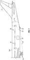
- FIG. 1 shows a schematic of an aircraft 100 having an embodiment of an energy absorbing rub strip 30 connected to the fuselage 25 near the tail 5 end of the aircraft 100.
- the rub strip 30 is positioned adjacent the passenger compartment 50 of the aircraft 100. As the rub strip 30 does not penetrate the skin of the fuselage 25, the rub strip 30 can be positioned adjacent the pressurized passenger compartment 50.
- a bulkhead 10 separates the pressurized passenger compartment from the tail 5 end of the aircraft 100.
- the landing gear 15 of the aircraft 100 is in a landing configuration and FIG. 1 shows the vector 28 from the landing gear 15 in the landing configuration to a potential initial contact point 26 on the fuselage if a contact event occurs during landing of the aircraft 100.
- the rub strip 30 is positioned along the bottom exterior of the fuselage to cover the potential initial contact point 26 during a contact event during landing and extends along the fuselage to cover the length of fuselage 25 that may also potentially contact the ground during a landing.
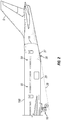
- FIG. 2 shows a schematic of an aircraft 100 having an embodiment of an energy absorbing rub strip 30 connected to the fuselage 25 near the tail 5 end of the aircraft 100.
- the rub strip 30 is positioned adjacent the passenger compartment 50 of the aircraft 100.
- a bulkhead 10 separates the pressurized passenger compartment from the tail 5 end of the aircraft 100.
- the landing gear 15 of the aircraft 100 is in a takeoff configuration and FIG. 2 shows the vector 29 from the landing gear 15 in the takeoff configuration to a potential initial contact point 27 on the fuselage if a contact event occurs during takeoff of the aircraft 100.
- the rub strip 30 is positioned along the bottom exterior of the fuselage to cover the potential initial contact point 27 during a contact event during takeoff and extends along the fuselage to cover the length of fuselage 25 that may also potentially contact the ground during a takeoff.
- the rub strip 30 has a length that extends beyond both the potential initial contact point 26 along the fuselage 25 for a contact event during landing and the potential initial contact point 27 along the fuselage 25 for a contact event during takeoff.
- FIG. 3 shows a close-up schematic of a rub strip 30 connected to the fuselage 25 of an aircraft 100 adjacent the passenger compartment 50.
- the rub strip 30 has a length 31 that extends forward of potential initial contact point 26 and rearward of potential initial contact point 27.
- the rub strip 30 may be connected to the fuselage 25 by a plurality of fasteners as would be appreciated by one of ordinary skill in the art having the benefit of this disclosure.
- the rub strip 30 includes a core material 33 having a thickness 32 that is configured to buckle or be crushed upon the application of force such as during a touch down event.
- the thickness 32 of the core material 33 may be a predetermined thickness estimated to withstand the force exerted on the rub strip 30 during a potential contact event in an effort to prevent damage to the skin and/or fuselage 25 of the aircraft 100.
- the core material 33 may be a material that buckles upon a touch down event protecting the fuselage 25 from being damaged.
- the core material 33 may be a honeycomb material such as an aluminum honeycomb.
- An aluminum honeycomb is a lightweight core material that offers excellent strength and corrosion resistance that may be comprised of a plurality of hexagonal shaped tubes, known as cells, of aluminum connected together.
- the core material 33 may be fabricated from aluminum honeycomb purchased from PLASCORE® of Zeeland, Michigan.
- the rub strip 30 includes a fairing 34 that covers the exterior of the core material 33.
- the fairing 34 may be connected to the fuselage 25 via a plurality of fasteners as would be appreciated by one of ordinary skill in the art having the benefit of this disclosure.
- the fairing 34 may be comprised of various abrasion-resistant materials.
- the fairing 34 may be titanium or a nickel-based metal.
- a fairing comprised of an abrasion-resistant material may decrease the impact force in the event of a contact event during landing and/or takeoff of an aircraft 100.
- FIG. 4 shows an embodiment of a rub strip 30 connected to a fuselage 25.
- Support members 37 may connect the rub strip 30 to structural members within the fuselage 25 of the aircraft 100.
- the rub strip 30 includes a core material 33 configured to buckle or collapse upon the application of a force such as during a ground contact during a landing or takeoff of the aircraft 100.
- the core material 33 is covered by a cover or fairing 34.
- the fairing 34 may be tapered for aerodynamic purposes.
- the core material 33 may not extend to the tapered end of the fairing 34 to minimize costs in forming the core material 33.
- the core material 33 may conform to the shape of the fairing 34.
- One embodiment of the rub strip 30 may weigh approximately 75 lbs.
- FIG. 5 shows a portion of the core material 33 buckled due to a contact event.
- the fairing 34 (not shown in FIG. 5 ) has been removed so that the extent of buckling of the core material 33 can be determined.
- the thickness 38 of the buckled material can be compared to the thickness 32 of the original core material 33 of the rub strip 30 to determine the amount of energy subjected to the rub strip 30 during the contact event.
- An inspection of the core material 33 after a contact event may be used to determine whether the structure of the aircraft 100 has been compromised due to the contact event. For example, a threshold buckled thickness can be determined based on the strength of the core material.
- the inspector can visually determine that the fuselage 25 of the aircraft 100 has not sustained any damage during the contact event rather than removing the core material 33 and inspecting the fuselage 25.
- the positioning of the rub strip 30 on the exterior of the fuselage 25 permits the rapid removal and replacement of the rub strip 30 in the event the rub strip 30 is damaged during a contact event.
- FIG 7 shows a cross-section of an embodiment of a rub strip 30.
- the rub strip 30 includes a core material 33 that is configured to buckle or crush upon a contact event with the ground. Core material 33 is covered by a fairing 34 that is connected to the fuselage 25 of an aircraft 100 via two mounting rails 35.
- the mounting rails 35 and fairing 34 may each be comprised of an abrasive-resistant material, such as titanium.
- FIG. 8 shows an embodiment of a rub strip 130 that has a dual density core material 133 covered by a fairing 34.
- the density, represented by shorter arrows 134, of the core material 133 adjacent the skin of the fuselage 25 has a lower density than the density, represented by longer arrows 135, of the core material 133 adjacent to the support members 37 connected to the fuselage 25.
- the support members 37 can withstand more force than the skin of the fuselage 25.
- the core material 133 that is adjacent to the support members 37 may have a higher density 135 than the density 134 of the core material 133 adjacent the skin.
- the use of a core material 133 having a dual density may provide a rub strip 130 that withstand a higher force from a ground impact and still potentially protect the fuselage 25 from becoming damaged.
- the dual density of the material 133 may be formed from aluminum honeycomb material comprised of two differently sized cells within the material 133. Portions of the material 133 having a first density may include a first sized cell or polygonal shaped tube of aluminum with the portions of the material 133 having a second density including a second sized cell of aluminum.
- FIG. 9 shows a method 200 of using an energy absorbing rub strip on an aircraft fuselage that includes the step 210 of positioning an abrasion-resistant fairing around a core material configured to collapse upon the application of a force to form a rub strip.
- the method 200 includes the step 220 of connecting the rub strip to the exterior of a fuselage of an aircraft.
- the method 200 optionally includes the step 230 of connecting the rub strip to the exterior of the fuselage adjacent to a passenger compartment.
- the method 200 optionally includes the step 240 of connecting the rub strip over potential initial contact points on the fuselage for ground contact events during landing and takeoff.
- the method 200 optionally includes the step 250 of determining the thickness of the core material deformed due to contact of the rub strip with the ground during a takeoff or landing of the aircraft.
- the abrasion-resistant fairing may be removed to permit the inspection of the core material to determine the amount of the core material that has buckled and/or collapsed.
- the method 200 optionally includes the step 260 of determining potential structural damage of the aircraft based on the thickness of core material deformed. For example, a threshold thickness of core material deformed may be predetermined based on the strength of the core material. If the thickness of the deformation is greater than or equal to a threshold thickness less, than it can be determined the aircraft did not sustain any structural damage. If the thickness of the deformation exceeds the threshold thickness, further investigation may be required.
- the method 200 optionally includes the step 270 of removing a deformed rub strip and placing a new rub strip on the fuselage of the aircraft.
- exemplary method 300 may include specification and design 304 of the aircraft 302 and material procurement 306.
- component and subassembly manufacturing 308 and system integration 310 of the aircraft 302 takes place.
- the aircraft 302 may go through certification and delivery 312 in order to be placed in service 314.
- routine maintenance and service 316 which may also include modification, reconfiguration, refurbishment, and so on).
- a system integrator may include without limitation any number of aircraft manufacturers and major-system subcontractors; a third party may include without limitation any number of vendors, subcontractors, and suppliers; and an operator may be an airline, leasing company, military entity, service organization, and so on.
- the aircraft 302 produced by exemplary method 300 may include an airframe 318 with a plurality of systems 320 and an interior 322.
- high-level systems 320 include one or more of a propulsion system 324, an electrical system 326, a hydraulic system 328, and an environmental system 330. Any number of other systems may be included.
- an aerospace example is shown, the principles of the disclosed embodiments may be applied to other industries, such as the automotive industry.
- Apparatus and methods embodied herein may be employed during any one or more of the stages of the aircraft manufacturing and service method 300.
- components or subassemblies corresponding to production process 308 may be fabricated or manufactured in a manner similar to components or subassemblies produced while the aircraft 302 is in service 314.
- one or more apparatus embodiments, method embodiments, or a combination thereof may be utilized during the production stages 308 and 310, for example, by substantially expediting assembly of or reducing the cost of an aircraft 302.
- one or more of apparatus embodiments, method embodiments, or a combination thereof may be utilized while the aircraft 302 is in service 314, for example and without limitation, to maintenance and service 316.
Landscapes
- Engineering & Computer Science (AREA)
- Mechanical Engineering (AREA)
- General Engineering & Computer Science (AREA)
- Aviation & Aerospace Engineering (AREA)
- Laminated Bodies (AREA)
Description
- An energy absorbing rub strip attached to the exterior of a fuselage of an aircraft that may prevent damage to the fuselage during a contact event. The rub strip may be comprised of a crushable core material covered with an abrasive-resistant fairing connected to the exterior of the fuselage adjacent to a passenger compartment. The rub strip may be positioned over a first potential contact point to potentially protect the fuselage if contact is made with the ground during takeoff of the aircraft. The rub strip may also be positioned over a second potential contact point to potentially protect the fuselage if contact is made with the ground during landing of the aircraft.
- During landing and takeoff of an aircraft, it is possible that a portion of the fuselage of the aircraft may contact the ground if the incidence angle of the aircraft is too great. Aircraft having a higher probability of a ground strike during landing and takeoff may include a tail absorber to protect the fuselage in the event of a ground strike.
FIG. 6 shows an aircraft having a tail absorber 1 protruding through thefuselage 25. A portion of the tail absorber 1 protrudes below thefuselage 25, so in the event that there is a ground strike during takeoff or landing, the tail absorber 1 contacts the ground instead of a portion of thefuselage 25. - The tail absorber 1 (shown in
FIG. 6 ) is adapted to absorb the energy from the ground strike. For example, the tail absorber 1 typically includes a telescopic mechanism within thefuselage 25 that crushes a crushable cartridge upon contact with the portion protruding below thefuselage 25 in an effort to absorb the energy from the ground strike. The cartridge may then be replaced with a new cartridge so that the system can potentially provide further protection against damage to the fuselage of the aircraft in the event of a ground strike. The typical tail absorber 1 mechanism may weigh approximately 350 lbs and provides protection against damage to the aircraft for ground strikes at a velocity near 5 feet per second. As the tail absorber 1 protrudes through thefuselage 25, the tail absorber is typically positioned behind the bulkhead isolating the fuselage from the pressurized passenger compartment. The introduction of advanced flight control laws that act as electronic tail strike protection systems has reduced the occurrences of ground strikes during landing and takeoff procedures. Further, advanced flight control law systems have reduced the force of a ground strike when it does occur. With advanced flight control systems a ground strike, will likely have a velocity of less than half of what was previously designed to protect. With the advent of advanced flight control laws, it would be beneficial to provide a fuselage protection mechanism that overcomes the potential disadvantages of the prior tail absorbing mechanisms. The present disclosure is directed to overcoming these disadvantages. -
US2012/0187717 A1 discloses an impact absorbing structure arranged to cover the underside of a helicopter. - The present invention relates to an energy absorbing rub strip comprising a dual density core material, the core material being configured to buckle under an application of a predetermined amount of force; and a fairing positioned over the core material, the fairing being configured to be attached to a fuselage of an aircraft, wherein support members connect the rub strip to structural members within the fuselage wherein the density of the core material adjacent skin of the fuselage is lower than the density of the core material adjacent the support members connected to the fuselage.
- The rub strip may further comprise at least two mounting rails attached to the fairing, wherein the fairing is connected to a fuselage of an aircraft via the mounting rails. The fairing and the at least two mounting rails may be comprised of titanium. The core material may be comprised of an aluminum honeycomb. The core material may be comprised of a dual density material. The fairing may be comprised of titanium or a nickel-based metal. The rub strip may have a length that extends beyond a potential expected landing contact point and a potential expected takeoff contact point on an aircraft fuselage.
- The present invention also relates to a method of using this energy absorbing rub strip on an aircraft fuselage, and comprises positioning the abrasion-resistant fairing around an exterior portion of the core material to form the energy absorbing rub strip, and connecting the energy absorbing rub strip to an exterior portion of a fuselage of an aircraft. The method may further comprise connecting the energy absorbing rub strip to the fuselage of the aircraft adjacent to a passenger compartment of the aircraft. The method may further comprise connecting the energy absorbing rub strip to the fuselage over a potential expected landing contact point and over a potential expected takeoff contact point. The method may include determining a thickness of core material deformed upon contact with the ground and determining if contact with the ground caused any structural damage to the fuselage based on the thickness of deformed core material. The method may further comprise replacing the abrasion-resistant fairing and the core material with a second abrasion-resistant fairing around an exterior portion of a second core material to form a second energy absorbing rub strip.
- The present invention also relates to an aircraft comprising a fuselage, a passenger compartment within an interior of the fuselage, a bulkhead separating the passenger compartment from an end of the fuselage with a tail, and the above referred to rub strip attached to an exterior of the fuselage adjacent to a portion of the passenger compartment. The rub strip may have a length that extends beyond a potential expected landing contact point on the fuselage and a potential expected takeoff contact point on the fuselage.
-
-
FIG. 1 shows a portion of an aircraft having an embodiment of a rub strip with the landing gear in a landing configuration; -
FIG. 2 shows a portion of an aircraft having an embodiment of rub strip with the landing gear in a takeoff configuration; -
FIG. 3 shows an embodiment of a rub strip attached to a portion of a fuselage; -
FIG. 4 shows an embodiment of a rub strip with connectors for connecting the rub strip to a fuselage; -
FIG. 5 shows an embodiment of a rub strip with the fairing removed and a portion buckled due to a contact event; -
FIG. 6 shows a prior art tail absorber; -
FIG. 7 shows a cross-section view of an embodiment of a rub strip; -
FIG. 8 shows an embodiment of a rub strip having a dual density core; -
FIG. 9 is a flow diagram of a method of using a rub strip on an aircraft fuselage; -
FIG.10 is an illustration of a flow diagram of an aircraft manufacturing and service methodology; and -
FIG. 11 is an illustration of a block diagram of an aircraft. - While the disclosure is susceptible to various modifications and alternative forms, specific embodiments have been shown by way of example in the drawings and will be described in detail herein.
-
FIG. 1 shows a schematic of anaircraft 100 having an embodiment of an energy absorbingrub strip 30 connected to thefuselage 25 near thetail 5 end of theaircraft 100. Therub strip 30 is positioned adjacent thepassenger compartment 50 of theaircraft 100. As therub strip 30 does not penetrate the skin of thefuselage 25, therub strip 30 can be positioned adjacent thepressurized passenger compartment 50. Abulkhead 10 separates the pressurized passenger compartment from thetail 5 end of theaircraft 100. Thelanding gear 15 of theaircraft 100 is in a landing configuration andFIG. 1 shows thevector 28 from thelanding gear 15 in the landing configuration to a potentialinitial contact point 26 on the fuselage if a contact event occurs during landing of theaircraft 100. Therub strip 30 is positioned along the bottom exterior of the fuselage to cover the potentialinitial contact point 26 during a contact event during landing and extends along the fuselage to cover the length offuselage 25 that may also potentially contact the ground during a landing. -
FIG. 2 shows a schematic of anaircraft 100 having an embodiment of an energy absorbingrub strip 30 connected to thefuselage 25 near thetail 5 end of theaircraft 100. Therub strip 30 is positioned adjacent thepassenger compartment 50 of theaircraft 100. Abulkhead 10 separates the pressurized passenger compartment from thetail 5 end of theaircraft 100. Thelanding gear 15 of theaircraft 100 is in a takeoff configuration andFIG. 2 shows thevector 29 from thelanding gear 15 in the takeoff configuration to a potentialinitial contact point 27 on the fuselage if a contact event occurs during takeoff of theaircraft 100. Therub strip 30 is positioned along the bottom exterior of the fuselage to cover the potentialinitial contact point 27 during a contact event during takeoff and extends along the fuselage to cover the length offuselage 25 that may also potentially contact the ground during a takeoff. Preferably, therub strip 30 has a length that extends beyond both the potentialinitial contact point 26 along thefuselage 25 for a contact event during landing and the potentialinitial contact point 27 along thefuselage 25 for a contact event during takeoff. -
FIG. 3 shows a close-up schematic of arub strip 30 connected to thefuselage 25 of anaircraft 100 adjacent thepassenger compartment 50. Therub strip 30 has alength 31 that extends forward of potentialinitial contact point 26 and rearward of potentialinitial contact point 27. Therub strip 30 may be connected to thefuselage 25 by a plurality of fasteners as would be appreciated by one of ordinary skill in the art having the benefit of this disclosure. Therub strip 30 includes acore material 33 having athickness 32 that is configured to buckle or be crushed upon the application of force such as during a touch down event. Thethickness 32 of thecore material 33 may be a predetermined thickness estimated to withstand the force exerted on therub strip 30 during a potential contact event in an effort to prevent damage to the skin and/orfuselage 25 of theaircraft 100. Thecore material 33 may be a material that buckles upon a touch down event protecting thefuselage 25 from being damaged. For example, thecore material 33 may be a honeycomb material such as an aluminum honeycomb. An aluminum honeycomb is a lightweight core material that offers excellent strength and corrosion resistance that may be comprised of a plurality of hexagonal shaped tubes, known as cells, of aluminum connected together. Thecore material 33 may be fabricated from aluminum honeycomb purchased from PLASCORE® of Zeeland, Michigan. Therub strip 30 includes a fairing 34 that covers the exterior of thecore material 33. The fairing 34 may be connected to thefuselage 25 via a plurality of fasteners as would be appreciated by one of ordinary skill in the art having the benefit of this disclosure. The fairing 34 may be comprised of various abrasion-resistant materials. For example, the fairing 34 may be titanium or a nickel-based metal. A fairing comprised of an abrasion-resistant material may decrease the impact force in the event of a contact event during landing and/or takeoff of anaircraft 100. -
FIG. 4 shows an embodiment of arub strip 30 connected to afuselage 25.Support members 37 may connect therub strip 30 to structural members within thefuselage 25 of theaircraft 100. Therub strip 30 includes acore material 33 configured to buckle or collapse upon the application of a force such as during a ground contact during a landing or takeoff of theaircraft 100. Thecore material 33 is covered by a cover orfairing 34. The fairing 34 may be tapered for aerodynamic purposes. Thecore material 33 may not extend to the tapered end of the fairing 34 to minimize costs in forming thecore material 33. Alternatively, thecore material 33 may conform to the shape of thefairing 34. One embodiment of therub strip 30 may weigh approximately 75 lbs. -
FIG. 5 shows a portion of thecore material 33 buckled due to a contact event. The fairing 34 (not shown inFIG. 5 ) has been removed so that the extent of buckling of thecore material 33 can be determined. Thethickness 38 of the buckled material can be compared to thethickness 32 of theoriginal core material 33 of therub strip 30 to determine the amount of energy subjected to therub strip 30 during the contact event. An inspection of thecore material 33 after a contact event may be used to determine whether the structure of theaircraft 100 has been compromised due to the contact event. For example, a threshold buckled thickness can be determined based on the strength of the core material. If thethickness 38 of the buckledcore material 33 is greater than or equal to the threshold thickness, the inspector can visually determine that thefuselage 25 of theaircraft 100 has not sustained any damage during the contact event rather than removing thecore material 33 and inspecting thefuselage 25. The positioning of therub strip 30 on the exterior of thefuselage 25 permits the rapid removal and replacement of therub strip 30 in the event therub strip 30 is damaged during a contact event. -
FIG 7 shows a cross-section of an embodiment of arub strip 30. Therub strip 30 includes acore material 33 that is configured to buckle or crush upon a contact event with the ground.Core material 33 is covered by a fairing 34 that is connected to thefuselage 25 of anaircraft 100 via two mountingrails 35. The mounting rails 35 and fairing 34 may each be comprised of an abrasive-resistant material, such as titanium. -
FIG. 8 shows an embodiment of arub strip 130 that has a dualdensity core material 133 covered by afairing 34. The density, represented byshorter arrows 134, of thecore material 133 adjacent the skin of thefuselage 25 has a lower density than the density, represented bylonger arrows 135, of thecore material 133 adjacent to thesupport members 37 connected to thefuselage 25. Thesupport members 37 can withstand more force than the skin of thefuselage 25. Thus, thecore material 133 that is adjacent to thesupport members 37 may have ahigher density 135 than thedensity 134 of thecore material 133 adjacent the skin. The use of acore material 133 having a dual density may provide arub strip 130 that withstand a higher force from a ground impact and still potentially protect thefuselage 25 from becoming damaged. The dual density of thematerial 133 may be formed from aluminum honeycomb material comprised of two differently sized cells within thematerial 133. Portions of the material 133 having a first density may include a first sized cell or polygonal shaped tube of aluminum with the portions of the material 133 having a second density including a second sized cell of aluminum. -
FIG. 9 shows amethod 200 of using an energy absorbing rub strip on an aircraft fuselage that includes thestep 210 of positioning an abrasion-resistant fairing around a core material configured to collapse upon the application of a force to form a rub strip. Themethod 200 includes thestep 220 of connecting the rub strip to the exterior of a fuselage of an aircraft. Themethod 200 optionally includes thestep 230 of connecting the rub strip to the exterior of the fuselage adjacent to a passenger compartment. Themethod 200 optionally includes thestep 240 of connecting the rub strip over potential initial contact points on the fuselage for ground contact events during landing and takeoff. Themethod 200 optionally includes thestep 250 of determining the thickness of the core material deformed due to contact of the rub strip with the ground during a takeoff or landing of the aircraft. The abrasion-resistant fairing may be removed to permit the inspection of the core material to determine the amount of the core material that has buckled and/or collapsed. Themethod 200 optionally includes thestep 260 of determining potential structural damage of the aircraft based on the thickness of core material deformed. For example, a threshold thickness of core material deformed may be predetermined based on the strength of the core material. If the thickness of the deformation is greater than or equal to a threshold thickness less, than it can be determined the aircraft did not sustain any structural damage. If the thickness of the deformation exceeds the threshold thickness, further investigation may be required. Themethod 200 optionally includes thestep 270 of removing a deformed rub strip and placing a new rub strip on the fuselage of the aircraft. - Referring to
FIGS. 10-11 , embodiments of the disclosure may be described in the context of an aircraft manufacturing andservice method 300 as shown inFIG. 10 and anaircraft 302 as shown inFIG. 11 . During pre-production,exemplary method 300 may include specification anddesign 304 of theaircraft 302 andmaterial procurement 306. During production, component andsubassembly manufacturing 308 andsystem integration 310 of theaircraft 302 takes place. Thereafter, theaircraft 302 may go through certification anddelivery 312 in order to be placed inservice 314. While inservice 314 by a customer, theaircraft 302 is scheduled for routine maintenance and service 316 (which may also include modification, reconfiguration, refurbishment, and so on). - Each of the processes of
method 300 may be performed or carried out by a system integrator, a third party, and/or an operator (e.g., a customer). For the purposes of this description, a system integrator may include without limitation any number of aircraft manufacturers and major-system subcontractors; a third party may include without limitation any number of vendors, subcontractors, and suppliers; and an operator may be an airline, leasing company, military entity, service organization, and so on. - As shown in
FIG. 11 , theaircraft 302 produced byexemplary method 300 may include anairframe 318 with a plurality ofsystems 320 and an interior 322. Examples of high-level systems 320 include one or more of apropulsion system 324, anelectrical system 326, ahydraulic system 328, and anenvironmental system 330. Any number of other systems may be included. Although an aerospace example is shown, the principles of the disclosed embodiments may be applied to other industries, such as the automotive industry. - Apparatus and methods embodied herein may be employed during any one or more of the stages of the aircraft manufacturing and
service method 300. For example, components or subassemblies corresponding toproduction process 308 may be fabricated or manufactured in a manner similar to components or subassemblies produced while theaircraft 302 is inservice 314. Also, one or more apparatus embodiments, method embodiments, or a combination thereof may be utilized during the production stages 308 and 310, for example, by substantially expediting assembly of or reducing the cost of anaircraft 302. Similarly, one or more of apparatus embodiments, method embodiments, or a combination thereof may be utilized while theaircraft 302 is inservice 314, for example and without limitation, to maintenance andservice 316.
Claims (15)
- An energy absorbing rub strip (30), the rub strip comprising:a dual density core material (33), the core material being configured to buckle under an application of a predetermined amount of force; anda fairing (34) positioned over the core material, the fairing being configured to be attached to a fuselage (25) of an aircraft,wherein support members (37) connect the rub strip (30) to structural members within the fuselage (25), wherein the density of the core material (33) adjacent skin of the fuselage (25) is lower than the density of the core material (33) adjacent the support members (37) connected to the fuselage (25).
- The rub strip (30) of claim 1, further comprising at least two mounting rails (35) attached to the fairing, wherein the fairing is connected to the fuselage (25) of an aircraft (100) via the mounting rails.
- The rub strip (30) of claim 2, wherein the fairing (34) and the at least two mounting rails (35) are comprised of titanium.
- The rub strip (30) of any preceding claim, wherein the core material (33) is comprised of aluminum honeycomb.
- The rub strip (30) of any preceding claim, wherein the core material (33) is comprised of a dual density material.
- The rub strip (30) of any preceding claim, wherein the fairing (34) is comprised of an abrasion-resistant material.
- The rub strip (30) of claim 6, wherein the fairing (34) is comprised of titanium.
- The rub strip (30) of claim 6, wherein the fairing (34) is comprised of nickel-based metal.
- The rub strip (30) of any preceding claim, wherein the rub strip has a length that extends beyond a potential expected landing contact point and a potential expected takeoff contact point on an aircraft fuselage (25).
- A method of using an energy absorbing rub strip (30) according to any of the preceding claims on an aircraft fuselage (25), the method comprising:positioning the abrasion-resistant fairing (34) around an exterior portion of the core material (33) to form the energy absorbing rub strip, andconnecting the energy absorbing rub strip to an exterior portion of a fuselage (25) of an aircraft (100).
- The method of claim 10, further comprising connecting the energy absorbing rub strip (30) to the fuselage (25) of the aircraft (100) adjacent to a passenger compartment (50) of the aircraft.
- The method of claim 11, further comprising connecting the energy absorbing rub strip (30) to the fuselage (25) over a potential expected landing contact point and over a potential expected takeoff contact point.
- The method of any of claims 10 to 12, further comprising:determining a thickness of core material (33) deformed upon contact with a ground surface; anddetermining if contact with the ground surface caused any structural damage to the fuselage (25) based on the thickness of core material deformed.
- The method of claim 13, further comprising replacing the abrasion-resistant fairing (34) and the core material (33) with a second abrasion-resistant fairing around an exterior portion of a second core material to form a second energy absorbing rub strip.
- An aircraft (100), the aircraft comprising:a fuselage (25);a passenger compartment (50) within an interior of the fuselage;a bulkhead (10) separating the passenger compartment from an end of the fuselage with a tail (5); anda rub strip (30) according to any of the preceding claims 1-9 attached to an exterior of the fuselage (25) adjacent to a portion of the passenger compartment.
Applications Claiming Priority (2)
| Application Number | Priority Date | Filing Date | Title |
|---|---|---|---|
| US14/249,576 US9637212B2 (en) | 2014-04-10 | 2014-04-10 | Aircraft body mounted energy absorbing rub strip |
| PCT/US2015/010964 WO2015156856A1 (en) | 2014-04-10 | 2015-01-12 | Aircraft body mounted energy absorbing rub strip |
Publications (2)
| Publication Number | Publication Date |
|---|---|
| EP3129220A1 EP3129220A1 (en) | 2017-02-15 |
| EP3129220B1 true EP3129220B1 (en) | 2020-09-09 |
Family
ID=52478044
Family Applications (1)
| Application Number | Title | Priority Date | Filing Date |
|---|---|---|---|
| EP15705109.5A Not-in-force EP3129220B1 (en) | 2014-04-10 | 2015-01-12 | Aircraft body mounted energy absorbing rub strip |
Country Status (3)
| Country | Link |
|---|---|
| US (1) | US9637212B2 (en) |
| EP (1) | EP3129220B1 (en) |
| WO (1) | WO2015156856A1 (en) |
Cited By (2)
| Publication number | Priority date | Publication date | Assignee | Title |
|---|---|---|---|---|
| EP4570648A1 (en) * | 2023-12-14 | 2025-06-18 | Airbus Operations (S.A.S.) | Aircraft comprising at least one removable device for absorbing energy by compression |
| US12384512B2 (en) | 2023-12-14 | 2025-08-12 | Airbus Operations (S.A.S.) | Device for absorbing energy by compression, aircraft comprising at least one such device |
Families Citing this family (6)
| Publication number | Priority date | Publication date | Assignee | Title |
|---|---|---|---|---|
| CN105438486B (en) * | 2015-12-11 | 2017-06-16 | 中国航空工业集团公司西安飞机设计研究所 | A kind of afterbody protection system |
| FR3062184B1 (en) * | 2017-01-26 | 2020-02-14 | Airbus Helicopters | PROTECTION AGAINST VIOLENT LANDINGS FOR AIRCRAFT |
| CN109850137A (en) * | 2019-03-18 | 2019-06-07 | 西安爱生技术集团公司 | Rapidly detachable rear fulcrum shock absorption mechanism for parachute drones |
| US11459085B2 (en) * | 2019-04-30 | 2022-10-04 | Textron Innovations Inc. | Energy attenuation stabilizers and methods |
| US20240336352A1 (en) * | 2021-08-03 | 2024-10-10 | ZSM Holdings, LLC | Systems and methods for aircraft tail strike prevention |
| FR3159588B1 (en) | 2024-02-23 | 2026-04-17 | Airbus Operations Sas | Compression energy absorption device comprising star-shaped absorption tubes; aircraft comprising at least one such device |
Family Cites Families (20)
| Publication number | Priority date | Publication date | Assignee | Title |
|---|---|---|---|---|
| US1694873A (en) * | 1926-09-03 | 1928-12-11 | Goodyear Zeppelin Corp | Landing bumper for airships |
| US4227593A (en) * | 1976-10-04 | 1980-10-14 | H. H. Robertson Company | Kinetic energy absorbing pad |
| US4411380A (en) | 1981-06-30 | 1983-10-25 | The United States Of America As Represented By The Administrator Of The National Aeronautics And Space Administration | Metal matrix composite structural panel construction |
| US4815678A (en) | 1987-12-04 | 1989-03-28 | The Boeing Company | Pivotally mounted high energy absorbing aircraft tail skid assembly having predetermined failure mode |
| US5069318A (en) * | 1989-12-26 | 1991-12-03 | Mcdonnell Douglas Corporation | Self-stabilized stepped crashworthy stiffeners |
| DE4313592C2 (en) | 1993-04-26 | 2000-02-17 | Daimler Chrysler Aerospace | Wide-body aircraft |
| AU5167396A (en) * | 1995-09-14 | 1997-04-01 | Sikorsky Aircraft Corporation | Energy absorbing landing gear/tail skid including means for indicating the magnitude of impact loads |
| US6098767A (en) * | 1997-12-15 | 2000-08-08 | Albert W. Unrath, Inc. | Cushion for crash attenuation system |
| US6245408B1 (en) * | 1999-05-19 | 2001-06-12 | Hexcel Corporation | Honeycomb core with controlled crush properties |
| US6523450B1 (en) * | 2000-09-20 | 2003-02-25 | Arthur Schreiber | Exterior armor for use on bottom of helicopter |
| US6938936B2 (en) | 2001-09-12 | 2005-09-06 | General Electric Company | Energy absorber with crash cans |
| JP3888630B2 (en) * | 2002-12-04 | 2007-03-07 | 川崎重工業株式会社 | Energy absorbing member and helicopter impact resistant structure using the same |
| DE102004029485B4 (en) * | 2004-06-18 | 2007-05-31 | Eads Deutschland Gmbh | Pulse-absorbing structure component |
| ES2279663B1 (en) | 2004-12-30 | 2008-08-01 | Airbus España, S.L. | AIRCRAFT WITH REAR FUSELAGE PROTECTION SHIELD. |
| US7997529B2 (en) * | 2006-01-19 | 2011-08-16 | The Boeing Company | Compliant panel for aircraft |
| WO2008016653A2 (en) | 2006-08-02 | 2008-02-07 | Meridian Automotive Systems, Inc. | Thermoplastic composite bumper system |
| US8215686B2 (en) | 2007-12-31 | 2012-07-10 | Sabic Innovative Plastics Ip B.V. | Fascia energy absorber, bumper system and process |
| JP5592672B2 (en) * | 2009-03-27 | 2014-09-17 | ホンダ・パテンツ・アンド・テクノロジーズ・ノース・アメリカ・エルエルシー | Skid rail for aircraft and method for manufacturing the same |
| FR2949431B1 (en) * | 2009-09-02 | 2011-07-29 | Eurocopter France | REUSABLE GIRAVION SABOT, AND GIRAVION PROVIDED WITH SUCH A SABOT |
| JP5129827B2 (en) | 2010-02-12 | 2013-01-30 | 三菱重工業株式会社 | Shock absorbing structure, shock absorbing structure manufacturing method, and moving body |
-
2014
- 2014-04-10 US US14/249,576 patent/US9637212B2/en not_active Expired - Fee Related
-
2015
- 2015-01-12 WO PCT/US2015/010964 patent/WO2015156856A1/en not_active Ceased
- 2015-01-12 EP EP15705109.5A patent/EP3129220B1/en not_active Not-in-force
Non-Patent Citations (1)
| Title |
|---|
| None * |
Cited By (3)
| Publication number | Priority date | Publication date | Assignee | Title |
|---|---|---|---|---|
| EP4570648A1 (en) * | 2023-12-14 | 2025-06-18 | Airbus Operations (S.A.S.) | Aircraft comprising at least one removable device for absorbing energy by compression |
| FR3156752A1 (en) * | 2023-12-14 | 2025-06-20 | Airbus Operations (S.A.S.) | Aircraft comprising at least one removable compression energy absorption device |
| US12384512B2 (en) | 2023-12-14 | 2025-08-12 | Airbus Operations (S.A.S.) | Device for absorbing energy by compression, aircraft comprising at least one such device |
Also Published As
| Publication number | Publication date |
|---|---|
| US9637212B2 (en) | 2017-05-02 |
| US20150336654A1 (en) | 2015-11-26 |
| WO2015156856A1 (en) | 2015-10-15 |
| EP3129220A1 (en) | 2017-02-15 |
Similar Documents
| Publication | Publication Date | Title |
|---|---|---|
| US9637212B2 (en) | Aircraft body mounted energy absorbing rub strip | |
| Herrmann et al. | Sandwich structures technology in commercial aviation | |
| Jun et al. | Design of aircraft structures against threat of bird strikes | |
| Fawcett et al. | Boeing composite airframe damage tolerance and service experience | |
| CN102030102B (en) | Horizontal tail front edge for bird strike-resisting airplane | |
| US20170129588A1 (en) | Truss-Reinforced Radome Crown Structure | |
| Perfetto et al. | Drop test simulation and validation of a full composite fuselage section of a regional aircraft | |
| EP2794395A1 (en) | Drag neutral vehicle window | |
| WO2014158295A2 (en) | High-wing-aircraft fuselage support structure | |
| Imran et al. | FE analysis for landing gear of test air craft | |
| Zhang et al. | Crashworthiness analysis of PRSEUS-based Blended-Wing-Body civil aircraft | |
| EP2415664A2 (en) | Wing-to-body fairing with spray-on foam and noise reduction method | |
| EP1963095A1 (en) | Protection device | |
| Tho et al. | Accurate bird strike simulation methodology for BA609 tiltrotor | |
| Mol et al. | Influence of new AA 2xxx layers on the strength and damage responses of fibre metal laminates during soft body impact | |
| Lu et al. | Effect on damage of aircraft windshield impacted by light UAV with different postures | |
| Pezzuti et al. | Structural composites for aircraft design | |
| Heimbs et al. | Bird strike analysis for impact-resistant design of aircraft wing krueger flap | |
| US11427310B2 (en) | Nacelle auxiliary landing gear | |
| Jang et al. | The study on improvement about structural integrity of main landing gear for rotorcraft | |
| Vaghela et al. | High Fidelity Airworthiness Bird and Drone Strike Analysis of On-Demand Air Mobility Service Aircraft | |
| Chandra et al. | Crashworthiness assessment in aircraft ditching incidents | |
| KR101199508B1 (en) | The bolt which is can distinguish the bending status and the method to determine the bending status | |
| Paz et al. | Impact response of aircraft structures enhanced with crushable energy absorbers: crashworthiness analysis and passenger injury assessment | |
| Arunakumara et al. | Evaluation of Crack Arrest Capability in the Stiffened Panel of a Transport Aircraft. |
Legal Events
| Date | Code | Title | Description |
|---|---|---|---|
| PUAI | Public reference made under article 153(3) epc to a published international application that has entered the european phase |
Free format text: ORIGINAL CODE: 0009012 |
|
| STAA | Information on the status of an ep patent application or granted ep patent |
Free format text: STATUS: REQUEST FOR EXAMINATION WAS MADE |
|
| 17P | Request for examination filed |
Effective date: 20160908 |
|
| AK | Designated contracting states |
Kind code of ref document: A1 Designated state(s): AL AT BE BG CH CY CZ DE DK EE ES FI FR GB GR HR HU IE IS IT LI LT LU LV MC MK MT NL NO PL PT RO RS SE SI SK SM TR |
|
| AX | Request for extension of the european patent |
Extension state: BA ME |
|
| DAX | Request for extension of the european patent (deleted) | ||
| STAA | Information on the status of an ep patent application or granted ep patent |
Free format text: STATUS: EXAMINATION IS IN PROGRESS |
|
| 17Q | First examination report despatched |
Effective date: 20170831 |
|
| GRAP | Despatch of communication of intention to grant a patent |
Free format text: ORIGINAL CODE: EPIDOSNIGR1 |
|
| STAA | Information on the status of an ep patent application or granted ep patent |
Free format text: STATUS: GRANT OF PATENT IS INTENDED |
|
| INTG | Intention to grant announced |
Effective date: 20200220 |
|
| GRAS | Grant fee paid |
Free format text: ORIGINAL CODE: EPIDOSNIGR3 |
|
| GRAJ | Information related to disapproval of communication of intention to grant by the applicant or resumption of examination proceedings by the epo deleted |
Free format text: ORIGINAL CODE: EPIDOSDIGR1 |
|
| GRAL | Information related to payment of fee for publishing/printing deleted |
Free format text: ORIGINAL CODE: EPIDOSDIGR3 |
|
| STAA | Information on the status of an ep patent application or granted ep patent |
Free format text: STATUS: EXAMINATION IS IN PROGRESS |
|
| INTC | Intention to grant announced (deleted) | ||
| GRAP | Despatch of communication of intention to grant a patent |
Free format text: ORIGINAL CODE: EPIDOSNIGR1 |
|
| STAA | Information on the status of an ep patent application or granted ep patent |
Free format text: STATUS: GRANT OF PATENT IS INTENDED |
|
| GRAA | (expected) grant |
Free format text: ORIGINAL CODE: 0009210 |
|
| STAA | Information on the status of an ep patent application or granted ep patent |
Free format text: STATUS: THE PATENT HAS BEEN GRANTED |
|
| INTG | Intention to grant announced |
Effective date: 20200804 |
|
| AK | Designated contracting states |
Kind code of ref document: B1 Designated state(s): AL AT BE BG CH CY CZ DE DK EE ES FI FR GB GR HR HU IE IS IT LI LT LU LV MC MK MT NL NO PL PT RO RS SE SI SK SM TR |
|
| REG | Reference to a national code |
Ref country code: GB Ref legal event code: FG4D |
|
| REG | Reference to a national code |
Ref country code: AT Ref legal event code: REF Ref document number: 1311061 Country of ref document: AT Kind code of ref document: T Effective date: 20200915 Ref country code: CH Ref legal event code: EP |
|
| REG | Reference to a national code |
Ref country code: IE Ref legal event code: FG4D |
|
| REG | Reference to a national code |
Ref country code: DE Ref legal event code: R096 Ref document number: 602015058723 Country of ref document: DE |
|
| REG | Reference to a national code |
Ref country code: LT Ref legal event code: MG4D |
|
| PG25 | Lapsed in a contracting state [announced via postgrant information from national office to epo] |
Ref country code: BG Free format text: LAPSE BECAUSE OF FAILURE TO SUBMIT A TRANSLATION OF THE DESCRIPTION OR TO PAY THE FEE WITHIN THE PRESCRIBED TIME-LIMIT Effective date: 20201209 Ref country code: NO Free format text: LAPSE BECAUSE OF FAILURE TO SUBMIT A TRANSLATION OF THE DESCRIPTION OR TO PAY THE FEE WITHIN THE PRESCRIBED TIME-LIMIT Effective date: 20201209 Ref country code: HR Free format text: LAPSE BECAUSE OF FAILURE TO SUBMIT A TRANSLATION OF THE DESCRIPTION OR TO PAY THE FEE WITHIN THE PRESCRIBED TIME-LIMIT Effective date: 20200909 Ref country code: SE Free format text: LAPSE BECAUSE OF FAILURE TO SUBMIT A TRANSLATION OF THE DESCRIPTION OR TO PAY THE FEE WITHIN THE PRESCRIBED TIME-LIMIT Effective date: 20200909 Ref country code: FI Free format text: LAPSE BECAUSE OF FAILURE TO SUBMIT A TRANSLATION OF THE DESCRIPTION OR TO PAY THE FEE WITHIN THE PRESCRIBED TIME-LIMIT Effective date: 20200909 Ref country code: GR Free format text: LAPSE BECAUSE OF FAILURE TO SUBMIT A TRANSLATION OF THE DESCRIPTION OR TO PAY THE FEE WITHIN THE PRESCRIBED TIME-LIMIT Effective date: 20201210 Ref country code: LT Free format text: LAPSE BECAUSE OF FAILURE TO SUBMIT A TRANSLATION OF THE DESCRIPTION OR TO PAY THE FEE WITHIN THE PRESCRIBED TIME-LIMIT Effective date: 20200909 |
|
| REG | Reference to a national code |
Ref country code: AT Ref legal event code: MK05 Ref document number: 1311061 Country of ref document: AT Kind code of ref document: T Effective date: 20200909 |
|
| REG | Reference to a national code |
Ref country code: NL Ref legal event code: MP Effective date: 20200909 |
|
| PG25 | Lapsed in a contracting state [announced via postgrant information from national office to epo] |
Ref country code: LV Free format text: LAPSE BECAUSE OF FAILURE TO SUBMIT A TRANSLATION OF THE DESCRIPTION OR TO PAY THE FEE WITHIN THE PRESCRIBED TIME-LIMIT Effective date: 20200909 Ref country code: RS Free format text: LAPSE BECAUSE OF FAILURE TO SUBMIT A TRANSLATION OF THE DESCRIPTION OR TO PAY THE FEE WITHIN THE PRESCRIBED TIME-LIMIT Effective date: 20200909 Ref country code: PL Free format text: LAPSE BECAUSE OF FAILURE TO SUBMIT A TRANSLATION OF THE DESCRIPTION OR TO PAY THE FEE WITHIN THE PRESCRIBED TIME-LIMIT Effective date: 20200909 |
|
| PG25 | Lapsed in a contracting state [announced via postgrant information from national office to epo] |
Ref country code: CZ Free format text: LAPSE BECAUSE OF FAILURE TO SUBMIT A TRANSLATION OF THE DESCRIPTION OR TO PAY THE FEE WITHIN THE PRESCRIBED TIME-LIMIT Effective date: 20200909 Ref country code: NL Free format text: LAPSE BECAUSE OF FAILURE TO SUBMIT A TRANSLATION OF THE DESCRIPTION OR TO PAY THE FEE WITHIN THE PRESCRIBED TIME-LIMIT Effective date: 20200909 Ref country code: PT Free format text: LAPSE BECAUSE OF FAILURE TO SUBMIT A TRANSLATION OF THE DESCRIPTION OR TO PAY THE FEE WITHIN THE PRESCRIBED TIME-LIMIT Effective date: 20210111 Ref country code: RO Free format text: LAPSE BECAUSE OF FAILURE TO SUBMIT A TRANSLATION OF THE DESCRIPTION OR TO PAY THE FEE WITHIN THE PRESCRIBED TIME-LIMIT Effective date: 20200909 Ref country code: SM Free format text: LAPSE BECAUSE OF FAILURE TO SUBMIT A TRANSLATION OF THE DESCRIPTION OR TO PAY THE FEE WITHIN THE PRESCRIBED TIME-LIMIT Effective date: 20200909 Ref country code: EE Free format text: LAPSE BECAUSE OF FAILURE TO SUBMIT A TRANSLATION OF THE DESCRIPTION OR TO PAY THE FEE WITHIN THE PRESCRIBED TIME-LIMIT Effective date: 20200909 |
|
| PG25 | Lapsed in a contracting state [announced via postgrant information from national office to epo] |
Ref country code: IS Free format text: LAPSE BECAUSE OF FAILURE TO SUBMIT A TRANSLATION OF THE DESCRIPTION OR TO PAY THE FEE WITHIN THE PRESCRIBED TIME-LIMIT Effective date: 20210109 Ref country code: ES Free format text: LAPSE BECAUSE OF FAILURE TO SUBMIT A TRANSLATION OF THE DESCRIPTION OR TO PAY THE FEE WITHIN THE PRESCRIBED TIME-LIMIT Effective date: 20200909 Ref country code: AT Free format text: LAPSE BECAUSE OF FAILURE TO SUBMIT A TRANSLATION OF THE DESCRIPTION OR TO PAY THE FEE WITHIN THE PRESCRIBED TIME-LIMIT Effective date: 20200909 Ref country code: AL Free format text: LAPSE BECAUSE OF FAILURE TO SUBMIT A TRANSLATION OF THE DESCRIPTION OR TO PAY THE FEE WITHIN THE PRESCRIBED TIME-LIMIT Effective date: 20200909 |
|
| REG | Reference to a national code |
Ref country code: DE Ref legal event code: R097 Ref document number: 602015058723 Country of ref document: DE |
|
| PG25 | Lapsed in a contracting state [announced via postgrant information from national office to epo] |
Ref country code: SK Free format text: LAPSE BECAUSE OF FAILURE TO SUBMIT A TRANSLATION OF THE DESCRIPTION OR TO PAY THE FEE WITHIN THE PRESCRIBED TIME-LIMIT Effective date: 20200909 |
|
| PLBE | No opposition filed within time limit |
Free format text: ORIGINAL CODE: 0009261 |
|
| STAA | Information on the status of an ep patent application or granted ep patent |
Free format text: STATUS: NO OPPOSITION FILED WITHIN TIME LIMIT |
|
| 26N | No opposition filed |
Effective date: 20210610 |
|
| PG25 | Lapsed in a contracting state [announced via postgrant information from national office to epo] |
Ref country code: DK Free format text: LAPSE BECAUSE OF FAILURE TO SUBMIT A TRANSLATION OF THE DESCRIPTION OR TO PAY THE FEE WITHIN THE PRESCRIBED TIME-LIMIT Effective date: 20200909 Ref country code: MC Free format text: LAPSE BECAUSE OF FAILURE TO SUBMIT A TRANSLATION OF THE DESCRIPTION OR TO PAY THE FEE WITHIN THE PRESCRIBED TIME-LIMIT Effective date: 20200909 Ref country code: SI Free format text: LAPSE BECAUSE OF FAILURE TO SUBMIT A TRANSLATION OF THE DESCRIPTION OR TO PAY THE FEE WITHIN THE PRESCRIBED TIME-LIMIT Effective date: 20200909 |
|
| REG | Reference to a national code |
Ref country code: CH Ref legal event code: PL |
|
| PG25 | Lapsed in a contracting state [announced via postgrant information from national office to epo] |
Ref country code: LU Free format text: LAPSE BECAUSE OF NON-PAYMENT OF DUE FEES Effective date: 20210112 |
|
| REG | Reference to a national code |
Ref country code: BE Ref legal event code: MM Effective date: 20210131 |
|
| PG25 | Lapsed in a contracting state [announced via postgrant information from national office to epo] |
Ref country code: IT Free format text: LAPSE BECAUSE OF FAILURE TO SUBMIT A TRANSLATION OF THE DESCRIPTION OR TO PAY THE FEE WITHIN THE PRESCRIBED TIME-LIMIT Effective date: 20200909 |
|
| PG25 | Lapsed in a contracting state [announced via postgrant information from national office to epo] |
Ref country code: CH Free format text: LAPSE BECAUSE OF NON-PAYMENT OF DUE FEES Effective date: 20210131 Ref country code: LI Free format text: LAPSE BECAUSE OF NON-PAYMENT OF DUE FEES Effective date: 20210131 |
|
| PG25 | Lapsed in a contracting state [announced via postgrant information from national office to epo] |
Ref country code: IE Free format text: LAPSE BECAUSE OF NON-PAYMENT OF DUE FEES Effective date: 20210112 |
|
| PG25 | Lapsed in a contracting state [announced via postgrant information from national office to epo] |
Ref country code: BE Free format text: LAPSE BECAUSE OF NON-PAYMENT OF DUE FEES Effective date: 20210131 |
|
| PG25 | Lapsed in a contracting state [announced via postgrant information from national office to epo] |
Ref country code: HU Free format text: LAPSE BECAUSE OF FAILURE TO SUBMIT A TRANSLATION OF THE DESCRIPTION OR TO PAY THE FEE WITHIN THE PRESCRIBED TIME-LIMIT; INVALID AB INITIO Effective date: 20150112 |
|
| P01 | Opt-out of the competence of the unified patent court (upc) registered |
Effective date: 20230516 |
|
| PG25 | Lapsed in a contracting state [announced via postgrant information from national office to epo] |
Ref country code: CY Free format text: LAPSE BECAUSE OF FAILURE TO SUBMIT A TRANSLATION OF THE DESCRIPTION OR TO PAY THE FEE WITHIN THE PRESCRIBED TIME-LIMIT Effective date: 20200909 |
|
| PG25 | Lapsed in a contracting state [announced via postgrant information from national office to epo] |
Ref country code: MK Free format text: LAPSE BECAUSE OF FAILURE TO SUBMIT A TRANSLATION OF THE DESCRIPTION OR TO PAY THE FEE WITHIN THE PRESCRIBED TIME-LIMIT Effective date: 20200909 |
|
| PGFP | Annual fee paid to national office [announced via postgrant information from national office to epo] |
Ref country code: DE Payment date: 20240129 Year of fee payment: 10 Ref country code: GB Payment date: 20240129 Year of fee payment: 10 |
|
| PGFP | Annual fee paid to national office [announced via postgrant information from national office to epo] |
Ref country code: FR Payment date: 20240125 Year of fee payment: 10 |
|
| PG25 | Lapsed in a contracting state [announced via postgrant information from national office to epo] |
Ref country code: TR Free format text: LAPSE BECAUSE OF FAILURE TO SUBMIT A TRANSLATION OF THE DESCRIPTION OR TO PAY THE FEE WITHIN THE PRESCRIBED TIME-LIMIT Effective date: 20200909 |
|
| PG25 | Lapsed in a contracting state [announced via postgrant information from national office to epo] |
Ref country code: MT Free format text: LAPSE BECAUSE OF FAILURE TO SUBMIT A TRANSLATION OF THE DESCRIPTION OR TO PAY THE FEE WITHIN THE PRESCRIBED TIME-LIMIT Effective date: 20200909 |
|
| REG | Reference to a national code |
Ref country code: DE Ref legal event code: R119 Ref document number: 602015058723 Country of ref document: DE |
|
| GBPC | Gb: european patent ceased through non-payment of renewal fee |
Effective date: 20250112 |
|
| PG25 | Lapsed in a contracting state [announced via postgrant information from national office to epo] |
Ref country code: DE Free format text: LAPSE BECAUSE OF NON-PAYMENT OF DUE FEES Effective date: 20250801 |
|
| PG25 | Lapsed in a contracting state [announced via postgrant information from national office to epo] |
Ref country code: GB Free format text: LAPSE BECAUSE OF NON-PAYMENT OF DUE FEES Effective date: 20250112 |
|
| PG25 | Lapsed in a contracting state [announced via postgrant information from national office to epo] |
Ref country code: FR Free format text: LAPSE BECAUSE OF NON-PAYMENT OF DUE FEES Effective date: 20250131 |