EP3128615A1 - Terminal - Google Patents
Terminal Download PDFInfo
- Publication number
- EP3128615A1 EP3128615A1 EP16181131.0A EP16181131A EP3128615A1 EP 3128615 A1 EP3128615 A1 EP 3128615A1 EP 16181131 A EP16181131 A EP 16181131A EP 3128615 A1 EP3128615 A1 EP 3128615A1
- Authority
- EP
- European Patent Office
- Prior art keywords
- pair
- portions
- positioning
- slit
- continuous
- Prior art date
- Legal status (The legal status is an assumption and is not a legal conclusion. Google has not performed a legal analysis and makes no representation as to the accuracy of the status listed.)
- Granted
Links
Images





Classifications
-
- H—ELECTRICITY
- H01—ELECTRIC ELEMENTS
- H01R—ELECTRICALLY-CONDUCTIVE CONNECTIONS; STRUCTURAL ASSOCIATIONS OF A PLURALITY OF MUTUALLY-INSULATED ELECTRICAL CONNECTING ELEMENTS; COUPLING DEVICES; CURRENT COLLECTORS
- H01R4/00—Electrically-conductive connections between two or more conductive members in direct contact, i.e. touching one another; Means for effecting or maintaining such contact; Electrically-conductive connections having two or more spaced connecting locations for conductors and using contact members penetrating insulation
- H01R4/24—Connections using contact members penetrating or cutting insulation or cable strands
- H01R4/2416—Connections using contact members penetrating or cutting insulation or cable strands the contact members having insulation-cutting edges, e.g. of tuning fork type
- H01R4/242—Connections using contact members penetrating or cutting insulation or cable strands the contact members having insulation-cutting edges, e.g. of tuning fork type the contact members being plates having a single slot
-
- H—ELECTRICITY
- H01—ELECTRIC ELEMENTS
- H01R—ELECTRICALLY-CONDUCTIVE CONNECTIONS; STRUCTURAL ASSOCIATIONS OF A PLURALITY OF MUTUALLY-INSULATED ELECTRICAL CONNECTING ELEMENTS; COUPLING DEVICES; CURRENT COLLECTORS
- H01R13/00—Details of coupling devices of the kinds covered by groups H01R12/70 or H01R24/00 - H01R33/00
- H01R13/02—Contact members
-
- H—ELECTRICITY
- H01—ELECTRIC ELEMENTS
- H01R—ELECTRICALLY-CONDUCTIVE CONNECTIONS; STRUCTURAL ASSOCIATIONS OF A PLURALITY OF MUTUALLY-INSULATED ELECTRICAL CONNECTING ELEMENTS; COUPLING DEVICES; CURRENT COLLECTORS
- H01R4/00—Electrically-conductive connections between two or more conductive members in direct contact, i.e. touching one another; Means for effecting or maintaining such contact; Electrically-conductive connections having two or more spaced connecting locations for conductors and using contact members penetrating insulation
- H01R4/24—Connections using contact members penetrating or cutting insulation or cable strands
- H01R4/2416—Connections using contact members penetrating or cutting insulation or cable strands the contact members having insulation-cutting edges, e.g. of tuning fork type
-
- H—ELECTRICITY
- H01—ELECTRIC ELEMENTS
- H01R—ELECTRICALLY-CONDUCTIVE CONNECTIONS; STRUCTURAL ASSOCIATIONS OF A PLURALITY OF MUTUALLY-INSULATED ELECTRICAL CONNECTING ELEMENTS; COUPLING DEVICES; CURRENT COLLECTORS
- H01R4/00—Electrically-conductive connections between two or more conductive members in direct contact, i.e. touching one another; Means for effecting or maintaining such contact; Electrically-conductive connections having two or more spaced connecting locations for conductors and using contact members penetrating insulation
- H01R4/24—Connections using contact members penetrating or cutting insulation or cable strands
- H01R4/2416—Connections using contact members penetrating or cutting insulation or cable strands the contact members having insulation-cutting edges, e.g. of tuning fork type
- H01R4/2445—Connections using contact members penetrating or cutting insulation or cable strands the contact members having insulation-cutting edges, e.g. of tuning fork type the contact members having additional means acting on the insulation or the wire, e.g. additional insulation penetrating means, strain relief means or wire cutting knives
- H01R4/245—Connections using contact members penetrating or cutting insulation or cable strands the contact members having insulation-cutting edges, e.g. of tuning fork type the contact members having additional means acting on the insulation or the wire, e.g. additional insulation penetrating means, strain relief means or wire cutting knives the additional means having two or more slotted flat portions
- H01R4/2454—Connections using contact members penetrating or cutting insulation or cable strands the contact members having insulation-cutting edges, e.g. of tuning fork type the contact members having additional means acting on the insulation or the wire, e.g. additional insulation penetrating means, strain relief means or wire cutting knives the additional means having two or more slotted flat portions forming a U-shape with slotted branches
-
- H—ELECTRICITY
- H02—GENERATION; CONVERSION OR DISTRIBUTION OF ELECTRIC POWER
- H02K—DYNAMO-ELECTRIC MACHINES
- H02K3/00—Details of windings
-
- H—ELECTRICITY
- H01—ELECTRIC ELEMENTS
- H01R—ELECTRICALLY-CONDUCTIVE CONNECTIONS; STRUCTURAL ASSOCIATIONS OF A PLURALITY OF MUTUALLY-INSULATED ELECTRICAL CONNECTING ELEMENTS; COUPLING DEVICES; CURRENT COLLECTORS
- H01R4/00—Electrically-conductive connections between two or more conductive members in direct contact, i.e. touching one another; Means for effecting or maintaining such contact; Electrically-conductive connections having two or more spaced connecting locations for conductors and using contact members penetrating insulation
- H01R4/24—Connections using contact members penetrating or cutting insulation or cable strands
- H01R4/2416—Connections using contact members penetrating or cutting insulation or cable strands the contact members having insulation-cutting edges, e.g. of tuning fork type
- H01R4/242—Connections using contact members penetrating or cutting insulation or cable strands the contact members having insulation-cutting edges, e.g. of tuning fork type the contact members being plates having a single slot
- H01R4/2425—Flat plates, e.g. multi-layered flat plates
Definitions
- This invention relates to a terminal.
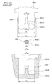
- FIG. 12 there has been known a terminal 903 to which a copper wire 902 of a coil end and a lead wire (not shown) of a generator are connected (see Japanese Laid-Open Patent Publication (Kokai) No. S63-92239 ).
- the terminal 903 is provided with a U-shaped groove 903A for connecting the copper wire 902 of the coil end and protrusions 903B for fixing the terminal.
- a groove width W1 of an innermost portion of the U-shaped groove 903A is smaller than a groove width W2 of an entrance portion of the same, and the terminal 903 is formed with stepped portions 903A1 for scraping off an insulation coating 902B of the copper wire 902.
- the groove width W1 of the innermost portion of the U-shaped groove 903A is smaller than an outer diameter V1 of a copper part 902A of the copper wire 902.
- the copper wire 902 is connected to the terminal 903 in the following manner:
- the copper wire 902 is inserted into an insertion groove 904A formed in a connection portion 904 of a bobbin part (not shown).
- a width U4 of the insertion groove 904A and an outer diameter V2 of the copper wire 902 have a relationship expressed by V2 ⁇ U4, and the copper wire 902 can be supported on a wall surface of the insertion groove 904A of the connection portion 904.
- An outer dimension W3 of the terminal 903 is substantially the same as a width U3 of the insertion groove 904C of the connection portion 904, and a width W4 of part of the terminal 903 including the protrusions 903B is larger than the width U3 of the insertion groove 904C of the connection portion 904 by approximately 0.1 to 1 mm.
- the terminal 903 when the terminal 903 is inserted into the insertion groove 904C of the connection portion 904, the copper wire 902 is pressed against a support base 904B located at the innermost of the insertion groove 904A of the connection portion 904, and the protrusions 903B of the terminal 903 byte into wall surfaces of the insertion groove 904C of the connection portion 904, whereby the terminal 903 is fixed in the connection portion 904.
- the copper wire 902 is relatively moved within the U-shaped groove 903A of the terminal 903 from the entrance toward the innermost of the U-shaped groove 903A, and hence the insulation coating 902B of the copper wire 902 is scraped off by the stepped portions 903A1 of the terminal 903, whereby the copper part 902A of the copper wire 902 is electrically and mechanically connected to the terminal 903.
- Each stepped portion 903A1 of the terminal 903 has an angle substantially equal to a right angle (see FIG. 12 ), and hence it is supposed that the insulation coating 902B of the copper wire 902 is scraped off by the stepped portions 903A1 without any problem.
- insulation coating 902B is thin, it is only required to reduce the difference between the groove width W1 and the groove width W2.
- the terminal 903 having the U-shaped groove 903A which is small in difference between the groove width W1 and the groove width W2 is formed by blanking a metal plate, it is impossible to stably form each stepped portion 903A1 of the terminal 903 into a desired shape, and hence it is difficult to make a sharp edge. This may make it difficult to positively scrape off the insulation coating 902B of the copper wire 902.
- the present invention has been made in view of these circumstances, and an object thereof is to provide a terminal that is capable of positively scraping off insulating coating of an electric wire.
- the present invention provides a terminal including a wire connection portion formed with a slit for receiving an electric wire and a cutout that communicates with the slit, characterized in that the wire connection portion comprises a pair of positioning portions that are disposed with the slit therebetween, and determine the position of the electric wire in a direction of a width of the slit, a pair of corner portions that are disposed with the slit therebetween, and scrape off insulation coating of the electric wire which is positioned by the pair of positioning portions, and a pair of supporting portions that are disposed with the slit therebetween, and support a conductive portion of the electric wire from which the insulation coating has been scraped off, in a state held therebetween, wherein the corner portion is located at an end portion of the supporting portion toward the positioning portion, wherein a spacing between the pair of supporting portions is smaller than a spacing between the pair of positioning portions, and wherein an inner surface of the cutout is continuous with a surface of the corner portion toward the positioning portion.
- an angle of the corner portion is not larger than a right angle.
- the inner surface of the cutout is formed by a flat surface which is continuous with the surface of the corner portion toward the positioning portion and a curved surface which is continuous with the flat surface.
- the inner surface of the cutout is formed by a curved surface which is continuous with the surface of the corner portion toward the positioning portion and a flat surface which is continuous with the curved surface.
- the inner surface of the cutout is a curved surface which is continuous with the surface of the corner portion toward the positioning portion.
- the surface of the corner portion toward the positioning portion and the inner surface of the cutout are smoothly continuous with each other.
- the flat surface which is continuous with the surface of the corner portion toward the positioning portion and the curved surface which is continuous with the flat surface are smoothly continuous with each other.
- the curved surface which is continuous with the surface of the corner portion toward the positioning portion and the flat surface which is continuous with the curved surface are smoothly continuous with each other.
- the wire connection portion includes a pair of wire guiding portions that are disposed with the slit therebetween, and guide the electric wire into between the pair of positioning portions.
- the pair of supporting portions include a pair of first supporting area portions that are disposed with the slit therebetween, and are adjacent to the positioning portions, respectively, a pair of second supporting area portions that are disposed with the slit therebetween, and receive the conductive portion having passed between the pair of first supporting area portions, and a pair of third supporting area portions that are disposed with the slit therebetween, and guide the conductive portion having passed between the pair of first supporting area portions into between the pair of second supporting area portions, and wherein a spacing between the pair of second supporting area portions is smaller than a spacing between the pair of first supporting area portions.
- the wire connection portion is formed by blanking a metal plate.
- a terminal 10 is comprised of a terminal base 20, a pair of wire connection portions 30, a lead wire-soldering portion 40, and a pair of press-in portions 50.
- the terminal 10 electrically connects a lead wire, not shown, and an electric wire 70 (see FIG. 5 ) of a coil end.
- the terminal base 20 has a rectangular plate shape.
- One of the pair of press-in portions 50 is continuous with one end of the terminal base 20 in a longitudinal direction DL, and the other of the pair of press-in portions 50 is continuous with the other end of the terminal base 20 in the longitudinal direction DL.
- the pair of press-in portions 50 each have a rectangular plate shape.
- the pair of press-in portions 50 are bent at right angles to the terminal base 20, respectively, and are opposed to each other in the longitudinal direction DL of the terminal base 20.
- Each press-in portion 50 has a plurality of protrusions 51. The protrusions 51 are located at opposite sides of each press-in portion 50.
- One of the pair of wire connection portions 30 is continuous with one side portion of the terminal base 20, and the other of the pair of wire connection portions 30 is continuous with the other side portion of the terminal base 20.
- the pair of wire connection portions 30 each have a rectangular plate shape.
- the pair of wire connection portions 30 are bent at right angles to the terminal base 20, respectively, and are opposed to each other in a lateral direction DS of the terminal base 20.
- Each wire connection portion 30 has a slit 31 formed in a central portion thereof, for receiving the electric wire 70.
- the slit 31 extends in a thickness direction DT of the terminal base 20.
- Surfaces of each wire connection portion 30 facing to the slit 31 except a curved surface located at the innermost of the slit 31 are flat surfaces.
- the lead wire-soldering portion 40 is continuous with one of side portions of the terminal base 20.
- the lead wire-soldering portion 40 is an L-shaped plate.
- the lead wire-soldering portion 40 is bent at right angles to the terminal base 20.
- the lead wire-soldering portion 40 is arranged side by side with one wire connection portion 30 with a space therebetween in the longitudinal direction DL of the terminal base 20.
- each wire connection portion 30 includes a pair of positioning portions 32, a pair of corner portions 33, a pair of supporting portions 34, a pair of wire guiding portions 35, etc.
- boundary lines B1 to B4 are indicated in FIG. 5 for convenience' sake to make clear the ranges of the positioning portions 32, the supporting portions 34, and the wire guiding portions 35.
- the pair of positioning portions 32 are disposed with the slit 31 therebetween.
- the pair of positioning portions 32 are part for positioning the electric wire 70 in a width direction DW of the slit 31.
- Each positioning portion 32 is an area sandwiched between the boundary line B1 and the boundary line B2.
- a spacing W10 between the pair of positioning portions 32 is approximately equal to an outer diameter V20 of an insulation coating 70B of the electric wire 70.
- the pair of corner portions 33 are disposed with the slit 31 therebetween.
- the pair of corner portions 33 are portions for scraping off the insulation coating 70B of the electric wire 70 which is positioned by the pair of positioning portions 32.
- the pair of supporting portions 34 are disposed with the slit 31 therebetween.
- the pair of supporting portions 34 are portions for holding and supporting therebetween a conductive portion 70A of the electric wire 70 from which the insulation coating 70B has been scraped off by the pair of corner portions 33.
- Each corner portion 33 is located on an end portion of an associated one of the supporting portions 34 toward the positioning portion 32.
- the pair of supporting portions 34 include a pair of first supporting area portions 34A, a pair of second supporting area portions 34B, and a pair of third supporting area portions 34C.
- the pair of first supporting area portions 34A are disposed with the slit 31 therebetween.
- the first supporting area portions 34A are adjacent to the positioning portions 32, respectively.
- Each first supporting area portion 34A is an area sandwiched between the boundary line B2 and the boundary line B3.
- a spacing W20 between the pair of first supporting area portions 34A has a dimension not larger than an outer diameter V10 of the conductive portion 70A of the electric wire 70. Further, the spacing W20 between the pair of first supporting area portions 34A is smaller than the spacing W10 between the pair of positioning portions 32.
- the pair of second supporting area portions 34B are disposed with the slit 31 therebetween.
- a spacing W30 between the pair of second supporting area portions 34B is smaller than the spacing W20 between the pair of first supporting area portions 34A.
- the pair of second supporting area portions 34B are portions for receiving the conductive portion 70A of the electric wire 70 having passed between the pair of first supporting area portions 34A, and supporting the conductive portion 70A of the electric wire 70 in a state held more strongly therebetween than the pair of first supporting area portions 34A.
- the pair of third supporting area portions 34C are disposed with the slit 31 therebetween.
- the third supporting area portions 34C are located between the first supporting area portions 34A and the second supporting area portions 34B, respectively.
- Each third supporting area portion 34C is an area sandwiched between the boundary line B3 and the boundary line B4.
- the pair of third supporting area portions 34C are part for guiding the conductive portion 70A of the electric wire 70 having passed between the pair of first supporting area portions 34A to the space between the pair of second supporting area portions 34B.
- a spacing between the pair of third supporting area portions 34C gradually becomes smaller as it shifts from the pair of first supporting area portions 34A to the pair of second supporting area portions 34B.
- the pair of wire guiding portions 35 are disposed with the slit 31 therebetween. A spacing between the pair of wire guiding portions 35 gradually becomes smaller as it shifts from the entrance toward the innermost of the slit 31.
- the pair of wire guiding portions 35 are portions for guiding the electric wire 70 into between the pair of positioning portions 32.
- each positioning portion 32 toward the supporting portion 34 is formed with a cutout 36 communicating with the slit 31.
- an inner surface 36A of the cutout 36 is smoothly continuous with a surface 33A of the corner portion 33 toward the positioning portion 32.
- the surface 33A of the corner portion 33 toward the positioning portion 32 is a flat surface.
- the inner surface 36A of the cutout 36 is formed by a flat surface 36B which is smoothly continuous with the surface 33A of the corner portion 33 toward the positioning portion 32 and a curved surface 36C which is smoothly continuous with the flat surface 36B.
- a boundary line B5 indicative of a boundary between the cutout 36 and the slit 31 is parallel to the central axis O of the slit 31.
- the terminal 10 To manufacture the terminal 10, first, by subjecting a metal plate (not shown) e.g. made of copper alloy to blanking, a plurality of terminals 10 each having a developed shape shown in FIG. 7 are simultaneously blanked (only one of the terminals 10 is shown in FIG. 7 ). At this time, the plurality of terminals 10 are connected by a carrier 60. Note that instead of blanking, the terminal 10 having a developed shape shown in FIG. 7 may be made by using a wire-cut electric discharge machining method.
- the terminal base 20, the pair of wire connection portions 30, the lead wire-soldering portion 40, and the pair of press-in portions 50 are formed by blanking. Further, since the cutouts 36 communicating with the slit 31 are formed in end portions of the positioning portions 32 toward the supporting portions 34, respectively, each corner portion 33 forms a right angle.
- the "right angle” includes not only a right angle in a strict sense, but also an angle which is slightly larger than 90 degrees.
- each terminal 10 is subjected to bending to thereby bend the portions (the wire connection portions 30, the lead wire soldering portion 40, and the press-in portions 50) of the terminal 10.
- the terminals 10 are cut off from a linking portion 60A of the carrier 60.
- lead wires are soldered to the lead wire-soldering portions 40 of the plurality of terminals 10, respectively.
- the press-in portions 50 of the plurality of terminals 10 are press-fitted into an inner side surface (surface toward the coil) of a ring-shaped cover to be accommodated in a motor, not shown.
- the plurality of terminals 10 are arranged in the cover in an annular form.
- the cover is for covering a ring-shaped portion of a base insulator of the motor, not shown.
- the cover is mounted on the ring-shaped portion of the base insulator.
- the electric wire 70 temporarily held by the ring-shaped portion of the base insulator is electrically and mechanically connected to the pair of wire connection portions 30 of each terminal 10.
- the electric wire 70 positioned at the entrance of the slit 31 is guided into between the pair of positioning portions 32 by the wire guiding portions 35 of the pair of wire connection portions 30.
- the position of the electric wire 70 in the width direction DW of the slit 31 is performed by the pair of positioning portions 32.
- the electric wire 70 inserted between the pair of positioning portions 32 passes between the pair of corner portions 33 and enters between the pair of first supporting area portions 34A.
- the spacing W20 between the pair of first supporting area portions 34A is smaller than the spacing W10 between the pair of positioning portions 32, and a difference between the spaces W20 and W10 is not smaller than the thickness of the insulation coating 70B of the electric wire 70.
- the angle of each corner portion 33 is the right angle, and the corner portions 33 are sharp. Therefore, when the electric wire 70 passes the space between the pair of corner portions 33, the insulation coating 70B of the electric wire 70 is positively scraped off, and the conductive portion 70A of the electric wire 70 is supported by the pair of first supporting area portions 34A.
- the conductive portion 70A of the electric wire 70 between the pair of first supporting area portions 34A is guided by the pair of third supporting area portions 34C into between the pair of second supporting area portions 34B. Since the spacing W30 between the pair of second supporting area portions 34B is smaller than the spacing W20 between the pair of first supporting area portions 34A, the conductive portion 70A of the electric wire 70 is supported by the pair of second supporting area portions 34B more strongly than the pair of first supporting area portions 34A. Thus, the electric wire 70 and each terminal 10 are electrically and mechanically connected to each other.
- the cutout 36 communicating with the slit 31 is formed in the end portion of each positioning portion 32 toward the supporting portion 34, even when the difference between the spacing W10 between the pair of positioning portions 32 and the spacing W20 between the pair of first supporting area portions 34A is small, it is possible to make each corner portions 33 sharp, and thereby positively scrape off the insulation coating 70B of the electric wire 70.
- each corner portion 33 toward the positioning portion 32 is smoothly continuous with the inner surface 36A of the cutout 36, and hence it is possible to suppress generation of so-called burr.
- the flat surface 36B and the curved surface 36C forming the inner surface 36A of the cutout 36 are smoothly continuous with each other, and hence it is possible to suppress generation of burr.
- each supporting portion 34 is formed by the first supporting area portion 34A, the second supporting area portion 34B, and the third supporting area portion 34C, and the spacing W20 between the pair of first supporting area portions 34A, the spacing W30 between the pair of second supporting area portions 34B, and the spacing between the pair of third supporting area portions 34C are all made different from each other, it is possible to enhance contact stability between the electric wire 70 and the terminal 10, compared with a wire connection portion (not shown) in which each supporting portion 34 is formed only by the first supporting area portion 34A, and the spacing between the pair of first supporting portions 34 is fixed.
- the wire connection portion 30 includes the pair of wire guiding portions 35, it is possible to easily insert the electric wire 70 into the slit 31.
- each wire connection portion 30 facing to the slit 31 except the curved surface located at the innermost of the slit 31 are flat surfaces, it is possible to easily manufacture a mold for blanking processing for forming the slit 31.
- the first to fourth variations differ from the embodiment shown in FIG. 1 in the shapes of the corner portion and the cutout.
- the same portions as those of the embodiment shown in FIG. 1 are denoted by the same reference numerals, and description thereof is omitted. The following description will be given only of different points from the embodiment shown in FIG. 1 .
- an angle ⁇ 1 of a corner portion 133 is smaller than 90°.
- a surface 133A of the corner portion 133 toward the positioning portion 32 is a flat surface.
- An inner surface 136A of a cutout 136 is formed by a curved surface 136C and a flat surface 136B.
- the curved surface 136C is smoothly continuous with the surface 133A of the corner portion 133 toward the positioning portion 32.
- the flat surface 136B is smoothly continuous with the curved surface 136C.
- the angle ⁇ 1 of the corner portion 133 is an angle formed by a surface 133B of the corner portion 133, which is parallel to the central axis O of the slit 31 (the surface 133B corresponds to part of the surface of the first supporting area portion 34A parallel to the central axis O of the slit 31), and the surface 133A of the corner portion 133 toward the positioning portion 32.
- the cutout 36 is formed in the end portion of the positioning portion 32 toward the supporting portion 34, in the first variation, the cutout 136 extends to the end portion of the supporting portion 34 toward the positioning portion 32.
- the angle ⁇ 1 of the corner portion 133 is smaller than 90°, it is possible to more positively scrape off the insulation coating 70B of the electric wire 70.
- an angle ⁇ 2 of a corner portion 233 is smaller than 90°.
- a surface 233A of the corner portion 233 toward the positioning portion 32 is a curved surface.
- An inner surface 236A of a cutout 236 is formed only by a curved surface 236C.
- the curved surface 236C is smoothly continuous with the surface 233A of the corner portion 233 toward the positioning portion 32.
- the angle ⁇ 2 of the corner portion 233 is an angle formed by a surface 233B of the corner portion 233, which is parallel to the central axis O of the slit 31 (the surface 233B corresponds to part of the surface of the first supporting area portion 34A parallel to the central axis O of the slit 31), and a tangential line TL2 of the surface 233A of the corner portion 233 toward the positioning portion 32.
- an angle ⁇ 3 of a corner portion 333 is larger than 90°.
- a surface 333A of the corner portion 333 toward the positioning portion 32 is a flat surface.
- An inner surface 338A of a cutout 336 is formed by a flat surface 336B and a curved surface 336C.
- the flat surface 336B is smoothly continuous with the surface 333A of the corner portion 333 toward the positioning portion 32.
- the curved surface 336C is smoothly continuous with the flat surface 336B.
- the angle ⁇ 3 of the corner portion 333 is an angle formed by a surface 333B of the corner portion 333, which is parallel to the central axis O of the slit 31 (the surface 333B corresponds to part of the surface of the first supporting area portion 34A parallel to the central axis O of the slit 31), and the surface 333A of the corner portion 333 toward the positioning portion 32.
- an angle ⁇ 4 of a corner portion 433 is larger than 90°.
- a surface 433A of the corner portion 433 toward the positioning portion 32 is a curved surface.
- An inner surface 436A of a cutout 436 is formed only by a curved surface 436C.
- the curved surface 436C is smoothly continuous with the surface 433A of the corner portion 433 toward the positioning portion 32.
- the angle ⁇ 4 of the corner portion 433 is an angle formed by a surface 433B of the corner portion 433, which is parallel to the central axis O of the slit 31 (the surface 433B corresponds to part of the surface of the first supporting area portion 34A parallel to the central axis O of the slit 31), and a tangential line TL4 of the surface 433A of the corner portion 433 toward the positioning portion 32.
- the wire connection portion 30 includes the wire guiding portions 35, the wire guiding portions 35 are not necessarily required.
- the spacing W20 between the pair of first supporting area portions 34A, the spacing W30 between the pair of second supporting area portions 34B, and the spacing between the pair of third supporting area portions 34C are all made different from each other, the spacing between the pair of supporting portions 34 may be made fixed without dividing the supporting portion 34 into three areas, or the spacing between the pair of supporting portions 34 may be gradually reduced toward the innermost of the slit 31.
- the terminal 10 is used for connection between the electric wire 70 of a coil end of the motor and the lead wire, this is not limitative, but the terminal according to the present invention may be used e.g. as a contact of a connector.
- the surfaces 33A, 133A, 233A, 333A, and 433A of the corner portions 33, 133, 233, 333, and 433, toward the positioning portion 32 are smoothly continuous with the inner surfaces 36A, 136A, 236A, 336A, and 436A of the cutouts 36, 136, 236, 336, and 436, respectively, these surfaces are not necessarily required to be smoothly continuous with each other.
- the flat surfaces 36B, 136B, and 336B, and the curved surfaces 36C, 136C, and 336C, forming the inner surfaces 36A, 136A, and 336A of the cutouts 36, 136, and 336, respectively are smoothly continuous with each other, respectively, these surfaces are not necessarily required to be smoothly continuous with each other.
- the electric wire is not limited to an electric wire having the insulation coating 70B which is an insulation coating film, such as an enamel wire, but an electric wire having the insulating coating part 70B made e.g. of resin is included.
Landscapes
- Engineering & Computer Science (AREA)
- Power Engineering (AREA)
- Connections Effected By Soldering, Adhesion, Or Permanent Deformation (AREA)
- Connections By Means Of Piercing Elements, Nuts, Or Screws (AREA)
Abstract
Description
- This invention relates to a terminal.
- Conventionally, as shown in
FIG. 12 , there has been known aterminal 903 to which acopper wire 902 of a coil end and a lead wire (not shown) of a generator are connected (seeJapanese Laid-Open Patent Publication (Kokai) No. S63-92239 - The
terminal 903 is provided with a U-shapedgroove 903A for connecting thecopper wire 902 of the coil end andprotrusions 903B for fixing the terminal. - A groove width W1 of an innermost portion of the U-shaped
groove 903A is smaller than a groove width W2 of an entrance portion of the same, and theterminal 903 is formed with stepped portions 903A1 for scraping off aninsulation coating 902B of thecopper wire 902. The groove width W1 of the innermost portion of the U-shapedgroove 903A is smaller than an outer diameter V1 of acopper part 902A of thecopper wire 902. - The
copper wire 902 is connected to theterminal 903 in the following manner: - First, the
copper wire 902 is inserted into aninsertion groove 904A formed in aconnection portion 904 of a bobbin part (not shown). A width U4 of theinsertion groove 904A and an outer diameter V2 of thecopper wire 902 have a relationship expressed by V2 ≧ U4, and thecopper wire 902 can be supported on a wall surface of theinsertion groove 904A of theconnection portion 904. - Next, the
terminal 903 is inserted into aninsertion groove 904C formed in theconnection portion 904. An outer dimension W3 of theterminal 903 is substantially the same as a width U3 of theinsertion groove 904C of theconnection portion 904, and a width W4 of part of theterminal 903 including theprotrusions 903B is larger than the width U3 of theinsertion groove 904C of theconnection portion 904 by approximately 0.1 to 1 mm. Therefore, when theterminal 903 is inserted into theinsertion groove 904C of theconnection portion 904, thecopper wire 902 is pressed against asupport base 904B located at the innermost of theinsertion groove 904A of theconnection portion 904, and theprotrusions 903B of theterminal 903 byte into wall surfaces of theinsertion groove 904C of theconnection portion 904, whereby theterminal 903 is fixed in theconnection portion 904. Thecopper wire 902 is relatively moved within the U-shapedgroove 903A of theterminal 903 from the entrance toward the innermost of the U-shapedgroove 903A, and hence theinsulation coating 902B of thecopper wire 902 is scraped off by the stepped portions 903A1 of theterminal 903, whereby thecopper part 902A of thecopper wire 902 is electrically and mechanically connected to theterminal 903. - Each stepped portion 903A1 of the
terminal 903 has an angle substantially equal to a right angle (seeFIG. 12 ), and hence it is supposed that the insulation coating 902B of thecopper wire 902 is scraped off by the stepped portions 903A1 without any problem. - If the
insulation coating 902B is thin, it is only required to reduce the difference between the groove width W1 and the groove width W2. - However, for example, assuming that the
terminal 903 having theU-shaped groove 903A which is small in difference between the groove width W1 and the groove width W2 is formed by blanking a metal plate, it is impossible to stably form each stepped portion 903A1 of theterminal 903 into a desired shape, and hence it is difficult to make a sharp edge. This may make it difficult to positively scrape off theinsulation coating 902B of thecopper wire 902. - The present invention has been made in view of these circumstances, and an object thereof is to provide a terminal that is capable of positively scraping off insulating coating of an electric wire.
- To attain the above object, the present invention provides a terminal including a wire connection portion formed with a slit for receiving an electric wire and a cutout that communicates with the slit, characterized in that the wire connection portion comprises a pair of positioning portions that are disposed with the slit therebetween, and determine the position of the electric wire in a direction of a width of the slit, a pair of corner portions that are disposed with the slit therebetween, and scrape off insulation coating of the electric wire which is positioned by the pair of positioning portions, and a pair of supporting portions that are disposed with the slit therebetween, and support a conductive portion of the electric wire from which the insulation coating has been scraped off, in a state held therebetween, wherein the corner portion is located at an end portion of the supporting portion toward the positioning portion, wherein a spacing between the pair of supporting portions is smaller than a spacing between the pair of positioning portions, and wherein an inner surface of the cutout is continuous with a surface of the corner portion toward the positioning portion.
- Preferably, an angle of the corner portion is not larger than a right angle.
- Preferably, the inner surface of the cutout is formed by a flat surface which is continuous with the surface of the corner portion toward the positioning portion and a curved surface which is continuous with the flat surface.
- Preferably, the inner surface of the cutout is formed by a curved surface which is continuous with the surface of the corner portion toward the positioning portion and a flat surface which is continuous with the curved surface.
- Preferably, the inner surface of the cutout is a curved surface which is continuous with the surface of the corner portion toward the positioning portion.
- Preferably, the surface of the corner portion toward the positioning portion and the inner surface of the cutout are smoothly continuous with each other.
- More preferably, the flat surface which is continuous with the surface of the corner portion toward the positioning portion and the curved surface which is continuous with the flat surface are smoothly continuous with each other.
- Further preferably, the curved surface which is continuous with the surface of the corner portion toward the positioning portion and the flat surface which is continuous with the curved surface are smoothly continuous with each other.
- Preferably, the wire connection portion includes a pair of wire guiding portions that are disposed with the slit therebetween, and guide the electric wire into between the pair of positioning portions.
- Preferably, the pair of supporting portions include a pair of first supporting area portions that are disposed with the slit therebetween, and are adjacent to the positioning portions, respectively, a pair of second supporting area portions that are disposed with the slit therebetween, and receive the conductive portion having passed between the pair of first supporting area portions, and a pair of third supporting area portions that are disposed with the slit therebetween, and guide the conductive portion having passed between the pair of first supporting area portions into between the pair of second supporting area portions, and wherein a spacing between the pair of second supporting area portions is smaller than a spacing between the pair of first supporting area portions.
- Preferably, the wire connection portion is formed by blanking a metal plate.
- According to the present invention, it is possible to provide a terminal that is capable of positively scraping off insulating coating of an electric wire.
- The above and other objects, features and advantages of the present invention will become more apparent from the following detailed description taken in conjunction with the accompanying drawings.
-
-
FIG. 1 is a perspective view of a terminal according to an embodiment of the present invention. -
FIG. 2 is a side view of the terminal shown inFIG. 1 . -
FIG. 3 is a front view of the terminal shown inFIG. 1 . -
FIG. 4 is a bottom view of the terminal shown inFIG. 1 . -
FIG. 5 is a front view of a wire connection portion of the terminal shown inFIG. 1 . -
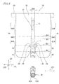
FIG. 6 is an enlarged view of part L appearing inFIG. 5 . -
FIG. 7 is a development view of the terminal shown inFIG. 1 . -
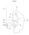
FIG. 8 is an enlarged view of a corner portion and a cutout of a first variation of the terminal shown inFIG. 1 . -
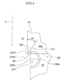
FIG. 9 is an enlarged view of a corner portion and a cutout of a second variation of the terminal shown inFIG. 1 . -
FIG. 10 is an enlarged view of a corner portion and a cutout of a third variation of the terminal shown inFIG. 1 . -
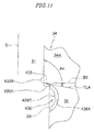
FIG. 11 is an enlarged view of a corner portion and a cutout of a fourth variation of the terminal shown inFIG. 1 . -
FIG. 12 is an enlarged vertical cross-sectional view of a conventional terminal and a connection portion. - The present invention will now be described in detail with reference to the drawings showing preferred embodiments thereof.
- As shown in
FIGS. 1 to 4 , aterminal 10 according to an embodiment of the present invention is comprised of aterminal base 20, a pair ofwire connection portions 30, a lead wire-solderingportion 40, and a pair of press-inportions 50. Theterminal 10 electrically connects a lead wire, not shown, and an electric wire 70 (seeFIG. 5 ) of a coil end. - The
terminal base 20 has a rectangular plate shape. - One of the pair of press-in
portions 50 is continuous with one end of theterminal base 20 in a longitudinal direction DL, and the other of the pair of press-inportions 50 is continuous with the other end of theterminal base 20 in the longitudinal direction DL. The pair of press-inportions 50 each have a rectangular plate shape. The pair of press-inportions 50 are bent at right angles to theterminal base 20, respectively, and are opposed to each other in the longitudinal direction DL of theterminal base 20. Each press-inportion 50 has a plurality ofprotrusions 51. Theprotrusions 51 are located at opposite sides of each press-inportion 50. - One of the pair of
wire connection portions 30 is continuous with one side portion of theterminal base 20, and the other of the pair ofwire connection portions 30 is continuous with the other side portion of theterminal base 20. The pair ofwire connection portions 30 each have a rectangular plate shape. The pair ofwire connection portions 30 are bent at right angles to theterminal base 20, respectively, and are opposed to each other in a lateral direction DS of theterminal base 20. Eachwire connection portion 30 has aslit 31 formed in a central portion thereof, for receiving theelectric wire 70. Theslit 31 extends in a thickness direction DT of theterminal base 20. Surfaces of eachwire connection portion 30 facing to theslit 31 except a curved surface located at the innermost of theslit 31 are flat surfaces. - The lead wire-soldering
portion 40 is continuous with one of side portions of theterminal base 20. The lead wire-solderingportion 40 is an L-shaped plate. The lead wire-solderingportion 40 is bent at right angles to theterminal base 20. The lead wire-solderingportion 40 is arranged side by side with onewire connection portion 30 with a space therebetween in the longitudinal direction DL of theterminal base 20. - As shown in
FIG. 5 , eachwire connection portion 30 includes a pair ofpositioning portions 32, a pair ofcorner portions 33, a pair of supportingportions 34, a pair ofwire guiding portions 35, etc. Note that boundary lines B1 to B4 are indicated inFIG. 5 for convenience' sake to make clear the ranges of thepositioning portions 32, the supportingportions 34, and thewire guiding portions 35. - The pair of
positioning portions 32 are disposed with theslit 31 therebetween. The pair ofpositioning portions 32 are part for positioning theelectric wire 70 in a width direction DW of theslit 31. Each positioningportion 32 is an area sandwiched between the boundary line B1 and the boundary line B2. A spacing W10 between the pair ofpositioning portions 32 is approximately equal to an outer diameter V20 of aninsulation coating 70B of theelectric wire 70. - The pair of
corner portions 33 are disposed with theslit 31 therebetween. The pair ofcorner portions 33 are portions for scraping off theinsulation coating 70B of theelectric wire 70 which is positioned by the pair ofpositioning portions 32. - The pair of supporting
portions 34 are disposed with theslit 31 therebetween. The pair of supportingportions 34 are portions for holding and supporting therebetween aconductive portion 70A of theelectric wire 70 from which theinsulation coating 70B has been scraped off by the pair ofcorner portions 33. Eachcorner portion 33 is located on an end portion of an associated one of the supportingportions 34 toward thepositioning portion 32. - The pair of supporting
portions 34 include a pair of first supportingarea portions 34A, a pair of second supportingarea portions 34B, and a pair of third supportingarea portions 34C. - The pair of first supporting
area portions 34A are disposed with theslit 31 therebetween. The first supportingarea portions 34A are adjacent to thepositioning portions 32, respectively. Each first supportingarea portion 34A is an area sandwiched between the boundary line B2 and the boundary line B3. A spacing W20 between the pair of first supportingarea portions 34A has a dimension not larger than an outer diameter V10 of theconductive portion 70A of theelectric wire 70. Further, the spacing W20 between the pair of first supportingarea portions 34A is smaller than the spacing W10 between the pair ofpositioning portions 32. - The pair of second supporting
area portions 34B are disposed with theslit 31 therebetween. A spacing W30 between the pair of second supportingarea portions 34B is smaller than the spacing W20 between the pair of first supportingarea portions 34A. The pair of second supportingarea portions 34B are portions for receiving theconductive portion 70A of theelectric wire 70 having passed between the pair of first supportingarea portions 34A, and supporting theconductive portion 70A of theelectric wire 70 in a state held more strongly therebetween than the pair of first supportingarea portions 34A. - The pair of third supporting
area portions 34C are disposed with theslit 31 therebetween. The third supportingarea portions 34C are located between the first supportingarea portions 34A and the second supportingarea portions 34B, respectively. Each third supportingarea portion 34C is an area sandwiched between the boundary line B3 and the boundary line B4. The pair of third supportingarea portions 34C are part for guiding theconductive portion 70A of theelectric wire 70 having passed between the pair of first supportingarea portions 34A to the space between the pair of second supportingarea portions 34B. - A spacing between the pair of third supporting
area portions 34C gradually becomes smaller as it shifts from the pair of first supportingarea portions 34A to the pair of second supportingarea portions 34B. - The pair of
wire guiding portions 35 are disposed with theslit 31 therebetween. A spacing between the pair ofwire guiding portions 35 gradually becomes smaller as it shifts from the entrance toward the innermost of theslit 31. The pair ofwire guiding portions 35 are portions for guiding theelectric wire 70 into between the pair ofpositioning portions 32. - An end portion of each positioning
portion 32 toward the supportingportion 34 is formed with acutout 36 communicating with theslit 31. As shown inFIG. 6 , aninner surface 36A of thecutout 36 is smoothly continuous with asurface 33A of thecorner portion 33 toward thepositioning portion 32. Thesurface 33A of thecorner portion 33 toward thepositioning portion 32 is a flat surface. Theinner surface 36A of thecutout 36 is formed by aflat surface 36B which is smoothly continuous with thesurface 33A of thecorner portion 33 toward thepositioning portion 32 and acurved surface 36C which is smoothly continuous with theflat surface 36B. A boundary line B5 indicative of a boundary between thecutout 36 and theslit 31 is parallel to the central axis O of theslit 31. - To manufacture the terminal 10, first, by subjecting a metal plate (not shown) e.g. made of copper alloy to blanking, a plurality of
terminals 10 each having a developed shape shown inFIG. 7 are simultaneously blanked (only one of theterminals 10 is shown inFIG. 7 ). At this time, the plurality ofterminals 10 are connected by acarrier 60. Note that instead of blanking, the terminal 10 having a developed shape shown inFIG. 7 may be made by using a wire-cut electric discharge machining method. - The
terminal base 20, the pair ofwire connection portions 30, the lead wire-solderingportion 40, and the pair of press-inportions 50 are formed by blanking. Further, since thecutouts 36 communicating with theslit 31 are formed in end portions of thepositioning portions 32 toward the supportingportions 34, respectively, eachcorner portion 33 forms a right angle. In this case, the "right angle" includes not only a right angle in a strict sense, but also an angle which is slightly larger than 90 degrees. - After blanking, each terminal 10 is subjected to bending to thereby bend the portions (the
wire connection portions 30, the leadwire soldering portion 40, and the press-in portions 50) of the terminal 10. - After bending, the
terminals 10 are cut off from a linkingportion 60A of thecarrier 60. - Thus, through the above-described process, the terminal 10 shown in
FIGS. 1 to 4 is completed. - Next, a description will be given of connection between the lead wire and the
electric wire 70 of the coil end, using theterminal 10. - First, lead wires are soldered to the lead wire-soldering
portions 40 of the plurality ofterminals 10, respectively. - Next, the press-in
portions 50 of the plurality ofterminals 10 are press-fitted into an inner side surface (surface toward the coil) of a ring-shaped cover to be accommodated in a motor, not shown. As a result, the plurality ofterminals 10 are arranged in the cover in an annular form. The cover is for covering a ring-shaped portion of a base insulator of the motor, not shown. - After that, the cover is mounted on the ring-shaped portion of the base insulator. At this time, the
electric wire 70 temporarily held by the ring-shaped portion of the base insulator is electrically and mechanically connected to the pair ofwire connection portions 30 of each terminal 10. - Hereafter, a process for connecting the
electric wire 70 and the pair ofwire connection portions 30 of each terminal 10 will be described in detail (seeFIG. 5 ). - First, the
electric wire 70 positioned at the entrance of theslit 31 is guided into between the pair ofpositioning portions 32 by thewire guiding portions 35 of the pair ofwire connection portions 30. The position of theelectric wire 70 in the width direction DW of theslit 31 is performed by the pair ofpositioning portions 32. - The
electric wire 70 inserted between the pair ofpositioning portions 32 passes between the pair ofcorner portions 33 and enters between the pair of first supportingarea portions 34A. The spacing W20 between the pair of first supportingarea portions 34A is smaller than the spacing W10 between the pair ofpositioning portions 32, and a difference between the spaces W20 and W10 is not smaller than the thickness of theinsulation coating 70B of theelectric wire 70. Further, the angle of eachcorner portion 33 is the right angle, and thecorner portions 33 are sharp. Therefore, when theelectric wire 70 passes the space between the pair ofcorner portions 33, theinsulation coating 70B of theelectric wire 70 is positively scraped off, and theconductive portion 70A of theelectric wire 70 is supported by the pair of first supportingarea portions 34A. - After that, the
conductive portion 70A of theelectric wire 70 between the pair of first supportingarea portions 34A is guided by the pair of third supportingarea portions 34C into between the pair of second supportingarea portions 34B. Since the spacing W30 between the pair of second supportingarea portions 34B is smaller than the spacing W20 between the pair of first supportingarea portions 34A, theconductive portion 70A of theelectric wire 70 is supported by the pair of second supportingarea portions 34B more strongly than the pair of first supportingarea portions 34A. Thus, theelectric wire 70 and each terminal 10 are electrically and mechanically connected to each other. - According to the present embodiment, since the
cutout 36 communicating with theslit 31 is formed in the end portion of each positioningportion 32 toward the supportingportion 34, even when the difference between the spacing W10 between the pair ofpositioning portions 32 and the spacing W20 between the pair of first supportingarea portions 34A is small, it is possible to make eachcorner portions 33 sharp, and thereby positively scrape off theinsulation coating 70B of theelectric wire 70. - Further, since the
cutout 36 communicating with theslit 31 is formed in the end portion of each positioningportion 32 toward the supportingportion 34, the operation for sharpening thecorner portions 33 is facilitated. - Further, the
surface 33A of eachcorner portion 33 toward thepositioning portion 32 is smoothly continuous with theinner surface 36A of thecutout 36, and hence it is possible to suppress generation of so-called burr. Similarly, theflat surface 36B and thecurved surface 36C forming theinner surface 36A of thecutout 36 are smoothly continuous with each other, and hence it is possible to suppress generation of burr. - Further, since each supporting
portion 34 is formed by the first supportingarea portion 34A, the second supportingarea portion 34B, and the third supportingarea portion 34C, and the spacing W20 between the pair of first supportingarea portions 34A, the spacing W30 between the pair of second supportingarea portions 34B, and the spacing between the pair of third supportingarea portions 34C are all made different from each other, it is possible to enhance contact stability between theelectric wire 70 and the terminal 10, compared with a wire connection portion (not shown) in which each supportingportion 34 is formed only by the first supportingarea portion 34A, and the spacing between the pair of first supportingportions 34 is fixed. - Further, since the
wire connection portion 30 includes the pair ofwire guiding portions 35, it is possible to easily insert theelectric wire 70 into theslit 31. - Further, since the surfaces of each
wire connection portion 30 facing to theslit 31 except the curved surface located at the innermost of theslit 31 are flat surfaces, it is possible to easily manufacture a mold for blanking processing for forming theslit 31. - Next, a description will be given of first to fourth variations of the embodiment shown in
FIG. 1 with reference toFIGS. 8 to 11 . - The first to fourth variations differ from the embodiment shown in
FIG. 1 in the shapes of the corner portion and the cutout. The same portions as those of the embodiment shown inFIG. 1 are denoted by the same reference numerals, and description thereof is omitted. The following description will be given only of different points from the embodiment shown inFIG. 1 . - Although in the embodiment shown in
FIG. 1 , the angle of thecorner portion 33 is a right angle, in the first variation shown inFIG. 8 , an angle θ1 of acorner portion 133 is smaller than 90°. Asurface 133A of thecorner portion 133 toward thepositioning portion 32 is a flat surface. - An
inner surface 136A of acutout 136 is formed by acurved surface 136C and aflat surface 136B. Thecurved surface 136C is smoothly continuous with thesurface 133A of thecorner portion 133 toward thepositioning portion 32. Theflat surface 136B is smoothly continuous with thecurved surface 136C. The angle θ1 of thecorner portion 133 is an angle formed by asurface 133B of thecorner portion 133, which is parallel to the central axis O of the slit 31 (thesurface 133B corresponds to part of the surface of the first supportingarea portion 34A parallel to the central axis O of the slit 31), and thesurface 133A of thecorner portion 133 toward thepositioning portion 32. - Although in the embodiment shown in
FIG. 1 , thecutout 36 is formed in the end portion of thepositioning portion 32 toward the supportingportion 34, in the first variation, thecutout 136 extends to the end portion of the supportingportion 34 toward thepositioning portion 32. - According to the first variation, since the angle θ1 of the
corner portion 133 is smaller than 90°, it is possible to more positively scrape off theinsulation coating 70B of theelectric wire 70. - In the second variation shown in
FIG. 9 , similarly to the first variation, an angle θ2 of acorner portion 233 is smaller than 90°. Asurface 233A of thecorner portion 233 toward thepositioning portion 32 is a curved surface. - An
inner surface 236A of acutout 236 is formed only by acurved surface 236C. Thecurved surface 236C is smoothly continuous with thesurface 233A of thecorner portion 233 toward thepositioning portion 32. The angle θ2 of thecorner portion 233 is an angle formed by asurface 233B of thecorner portion 233, which is parallel to the central axis O of the slit 31 (thesurface 233B corresponds to part of the surface of the first supportingarea portion 34A parallel to the central axis O of the slit 31), and a tangential line TL2 of thesurface 233A of thecorner portion 233 toward thepositioning portion 32. - According to the second variation, it is possible to obtain the same advantageous effects as provided by the first variation.
- In the third variation shown in
FIG. 10 , an angle θ3 of acorner portion 333 is larger than 90°. Asurface 333A of thecorner portion 333 toward thepositioning portion 32 is a flat surface. - An inner surface 338A of a
cutout 336 is formed by aflat surface 336B and acurved surface 336C. Theflat surface 336B is smoothly continuous with thesurface 333A of thecorner portion 333 toward thepositioning portion 32. Thecurved surface 336C is smoothly continuous with theflat surface 336B. The angle θ3 of thecorner portion 333 is an angle formed by asurface 333B of thecorner portion 333, which is parallel to the central axis O of the slit 31 (thesurface 333B corresponds to part of the surface of the first supportingarea portion 34A parallel to the central axis O of the slit 31), and thesurface 333A of thecorner portion 333 toward thepositioning portion 32. - According to the third variation, it is possible to obtain the same advantageous effects as provided by the embodiment shown in
FIG. 1 . - In the fourth variation shown in
FIG. 11 , an angle θ4 of acorner portion 433 is larger than 90°. Asurface 433A of thecorner portion 433 toward thepositioning portion 32 is a curved surface. - An
inner surface 436A of acutout 436 is formed only by acurved surface 436C. Thecurved surface 436C is smoothly continuous with thesurface 433A of thecorner portion 433 toward thepositioning portion 32. The angle θ4 of thecorner portion 433 is an angle formed by asurface 433B of thecorner portion 433, which is parallel to the central axis O of the slit 31 (thesurface 433B corresponds to part of the surface of the first supportingarea portion 34A parallel to the central axis O of the slit 31), and a tangential line TL4 of thesurface 433A of thecorner portion 433 toward thepositioning portion 32. - According to the fourth variation, it is possible to obtain the same advantageous effects as provided by the third variation.
- Note that although in the above-described embodiment and variations, the
wire connection portion 30 includes thewire guiding portions 35, thewire guiding portions 35 are not necessarily required. - Further, although in the above-described embodiment and variations, the spacing W20 between the pair of first supporting
area portions 34A, the spacing W30 between the pair of second supportingarea portions 34B, and the spacing between the pair of third supportingarea portions 34C are all made different from each other, the spacing between the pair of supportingportions 34 may be made fixed without dividing the supportingportion 34 into three areas, or the spacing between the pair of supportingportions 34 may be gradually reduced toward the innermost of theslit 31. - Although in the above-described embodiment and variations, the terminal 10 is used for connection between the
electric wire 70 of a coil end of the motor and the lead wire, this is not limitative, but the terminal according to the present invention may be used e.g. as a contact of a connector. - Further, although in the above-described embodiment and variations, the
surfaces corner portions positioning portion 32, are smoothly continuous with theinner surfaces cutouts flat surfaces curved surfaces inner surfaces cutouts - Note that the electric wire is not limited to an electric wire having the
insulation coating 70B which is an insulation coating film, such as an enamel wire, but an electric wire having the insulatingcoating part 70B made e.g. of resin is included.
Claims (11)
- A terminal including a wire connection portion formed with a slit for receiving an electric wire and a cutout that communicates with the slit,
characterized in that:the wire connection portion comprises:a pair of positioning portions that are disposed with the slit therebetween, and determine the position of the electric wire in a direction of a width of the slit;a pair of corner portions that are disposed with the slit therebetween, and scrape off insulation coating of the electric wire which is positioned by the pair of positioning portions; anda pair of supporting portions that are disposed with the slit therebetween, and support a conductive portion of the electric wire from which the insulation coating has been scraped off, in a state held therebetween,wherein the corner portion is located at an end portion of the supporting portion toward the positioning portion,wherein a spacing between the pair of supporting portions is smaller than a spacing between the pair of positioning portions, andwherein an inner surface of the cutout is continuous with a surface of the corner portion toward the positioning portion. - The terminal according to claim 1, wherein an angle of the corner portion is not larger than a right angle.
- The terminal according to claim 1 or 2, wherein the inner surface of the cutout is formed by a flat surface which is continuous with the surface of the corner portion toward the positioning portion and a curved surface which is continuous with the flat surface.
- The terminal according to claim 1 or 2, wherein the inner surface of the cutout is formed by a curved surface which is continuous with the surface of the corner portion toward the positioning portion and a flat surface which is continuous with the curved surface.
- The terminal according to claim 1 or 2, wherein the inner surface of the cutout is a curved surface which is continuous with the surface of the corner portion toward the positioning portion.
- The terminal according to claim 1 or 2, wherein the surface of the corner portion toward the positioning portion and the inner surface of the cutout are smoothly continuous with each other.
- The terminal according to claim 3, wherein the flat surface which is continuous with the surface of the corner portion toward the positioning portion and the curved surface which is continuous with the flat surface are smoothly continuous with each other.
- The terminal according to claim 4, wherein the curved surface which is continuous with the surface of the corner portion toward the positioning portion and the flat surface which is continuous with the curved surface are smoothly continuous with each other.
- The terminal according to one of claims 1 to 8, wherein the wire connection portion includes a pair of wire guiding portions that are disposed with the slit therebetween, and guide the electric wire into between the pair of positioning portions.
- The terminal according to one of claims 1 to 9, wherein said pair of supporting portions include:a pair of first supporting area portions that are disposed with the slit therebetween, and are adjacent to the positioning portions, respectively;a pair of second supporting area portions that are disposed with the slit therebetween, and receive the conductive portion having passed between the pair of first supporting area portions; anda pair of third supporting area portions that are disposed with the slit therebetween, and guide the conductive portion having passed between the pair of first supporting area portions into between the pair of second supporting area portions, andwherein a spacing between the pair of second supporting area portions is smaller than a spacing between the pair of first supporting area portions.
- The terminal according to one of claims 1 to 10, wherein the wire connection portion is formed by blanking a metal plate.
Applications Claiming Priority (1)
| Application Number | Priority Date | Filing Date | Title |
|---|---|---|---|
| JP2015153248A JP6634235B2 (en) | 2015-08-03 | 2015-08-03 | Terminal |
Publications (2)
| Publication Number | Publication Date |
|---|---|
| EP3128615A1 true EP3128615A1 (en) | 2017-02-08 |
| EP3128615B1 EP3128615B1 (en) | 2021-04-28 |
Family
ID=56551226
Family Applications (1)
| Application Number | Title | Priority Date | Filing Date |
|---|---|---|---|
| EP16181131.0A Active EP3128615B1 (en) | 2015-08-03 | 2016-07-26 | Terminal |
Country Status (4)
| Country | Link |
|---|---|
| US (1) | US9941602B2 (en) |
| EP (1) | EP3128615B1 (en) |
| JP (1) | JP6634235B2 (en) |
| CN (1) | CN106410463B (en) |
Families Citing this family (1)
| Publication number | Priority date | Publication date | Assignee | Title |
|---|---|---|---|---|
| JP6486419B2 (en) | 2017-07-18 | 2019-03-20 | 京セラ株式会社 | connector |
Citations (6)
| Publication number | Priority date | Publication date | Assignee | Title |
|---|---|---|---|---|
| US4333700A (en) * | 1980-05-23 | 1982-06-08 | Bell Telephone Laboratories, Incorporated | Insulation-penetrating slotted beam contact element |
| JPS6392239A (en) | 1986-10-06 | 1988-04-22 | Nippon Denso Co Ltd | Terminal connecting mechanism for generator |
| EP0320310A2 (en) * | 1987-12-11 | 1989-06-14 | Molex Incorporated | High contact pressure insulation displacement terminal for multi-strand wire |
| DE19736119A1 (en) * | 1997-08-20 | 1999-03-11 | Lumberg Karl Gmbh & Co | Insulation cutting clamp |
| EP1006614A2 (en) * | 1998-12-03 | 2000-06-07 | Sumitomo Wiring Systems, Ltd. | Pressure-contact terminal and electric connection box containing pressure-contact terminals |
| DE10065189A1 (en) * | 2000-12-23 | 2002-07-18 | Geyer Ag | Clamping part for connecting an insulated cable has blades spread by cable insertion that cut through or separate insulation during further insertion and contact core under pressure of spreading |
Family Cites Families (16)
| Publication number | Priority date | Publication date | Assignee | Title |
|---|---|---|---|---|
| US4116522A (en) * | 1976-07-09 | 1978-09-26 | Amp Incorporated | Slotted terminal |
| US4141618A (en) * | 1977-12-05 | 1979-02-27 | Amp Incorporated | Transversely slotted barrel terminal |
| US4230391A (en) * | 1978-09-01 | 1980-10-28 | Bunker Ramo Corporation | Electrical contact |
| JPS5555975U (en) * | 1978-10-09 | 1980-04-16 | ||
| US4212509A (en) * | 1978-12-11 | 1980-07-15 | Essex Group, Inc. | Electrical connector assembly |
| US4431249A (en) * | 1982-03-31 | 1984-02-14 | Amp Incorporated | Male/female cable connector |
| JPS6389672U (en) * | 1986-12-01 | 1988-06-10 | ||
| US5683266A (en) * | 1994-03-31 | 1997-11-04 | Bitron S.P.A. | Device and method for the mechnical and electrical connection of a terminal |
| US6142817A (en) * | 1997-03-07 | 2000-11-07 | Marconi Communications Inc. | Insulation displacement connector |
| US6908331B2 (en) * | 2002-09-27 | 2005-06-21 | Donald C. Brown | Insulation stripping connector for insulated wires |
| DE102004019360A1 (en) * | 2004-04-21 | 2005-11-17 | Tyco Electronics Amp Gmbh | Insulated connector contact element |
| US7556543B2 (en) * | 2007-10-29 | 2009-07-07 | Tyco Electronics Corporation | One-piece PC board magnet wire terminal |
| DE102009029298A1 (en) * | 2009-09-09 | 2011-03-10 | Robert Bosch Gmbh | Winding body for a magnetic assembly of a solenoid valve and method for winding a winding wire on a winding body |
| WO2013039657A2 (en) * | 2011-09-14 | 2013-03-21 | Interplex Industries, Inc. | Large deflection constrained insulation displacement terminal and connector |
| CN110890639B (en) * | 2013-04-18 | 2021-07-06 | 安费诺富加宜(亚洲)私人有限公司 | Insulation displacement connector and contact thereof |
| JP2015076208A (en) * | 2013-10-07 | 2015-04-20 | 矢崎総業株式会社 | Electric wire terminal joining structure, resistance welding electrode, electric wire terminal joining method |
-
2015
- 2015-08-03 JP JP2015153248A patent/JP6634235B2/en active Active
-
2016
- 2016-07-22 US US15/217,329 patent/US9941602B2/en active Active
- 2016-07-26 EP EP16181131.0A patent/EP3128615B1/en active Active
- 2016-08-01 CN CN201610621380.XA patent/CN106410463B/en active Active
Patent Citations (6)
| Publication number | Priority date | Publication date | Assignee | Title |
|---|---|---|---|---|
| US4333700A (en) * | 1980-05-23 | 1982-06-08 | Bell Telephone Laboratories, Incorporated | Insulation-penetrating slotted beam contact element |
| JPS6392239A (en) | 1986-10-06 | 1988-04-22 | Nippon Denso Co Ltd | Terminal connecting mechanism for generator |
| EP0320310A2 (en) * | 1987-12-11 | 1989-06-14 | Molex Incorporated | High contact pressure insulation displacement terminal for multi-strand wire |
| DE19736119A1 (en) * | 1997-08-20 | 1999-03-11 | Lumberg Karl Gmbh & Co | Insulation cutting clamp |
| EP1006614A2 (en) * | 1998-12-03 | 2000-06-07 | Sumitomo Wiring Systems, Ltd. | Pressure-contact terminal and electric connection box containing pressure-contact terminals |
| DE10065189A1 (en) * | 2000-12-23 | 2002-07-18 | Geyer Ag | Clamping part for connecting an insulated cable has blades spread by cable insertion that cut through or separate insulation during further insertion and contact core under pressure of spreading |
Also Published As
| Publication number | Publication date |
|---|---|
| JP6634235B2 (en) | 2020-01-22 |
| US9941602B2 (en) | 2018-04-10 |
| US20170040714A1 (en) | 2017-02-09 |
| EP3128615B1 (en) | 2021-04-28 |
| CN106410463A (en) | 2017-02-15 |
| CN106410463B (en) | 2019-11-05 |
| JP2017033786A (en) | 2017-02-09 |
Similar Documents
| Publication | Publication Date | Title |
|---|---|---|
| CN101512845B (en) | Connector | |
| US11165172B2 (en) | Terminal and wire with terminal | |
| CN103814479B (en) | Constrained Large Deflection Insulation Displacement Terminals and Connectors | |
| CN106532308B (en) | Sheet metal parts with improved connection bump geometry | |
| JP6244332B2 (en) | Connector and connector manufacturing method | |
| US20190237919A1 (en) | Method For Producing A Modularly Configurable Coaxial Plug | |
| CN107275910A (en) | The manufacture method of electric connector | |
| KR102076247B1 (en) | Electrical Contact | |
| CN112242633A (en) | Connection structure, method of forming connection structure, and cable of connection structure | |
| US7357661B2 (en) | Pressure coupling connector | |
| KR102338051B1 (en) | Coaxial Connectors and Coaxial Connectors with Coaxial Cables | |
| EP3128615B1 (en) | Terminal | |
| CN104733873A (en) | Connection device and production method therefor | |
| US11095070B2 (en) | Electrical connector | |
| CN207638110U (en) | Connection terminal and coaxial connector | |
| CN107305983B (en) | connector for wire | |
| EP4170825A1 (en) | Linearized magnet wire connector | |
| CN115966983B (en) | cutter | |
| US10862379B2 (en) | Stator assembling method for motor, stator structure for motor, and crimp terminal | |
| CN105830289A (en) | Method for crimping electrical wire to terminal | |
| GB2223888A (en) | Assembled commutator for electric motor | |
| JP6702665B2 (en) | L-type coaxial connector and manufacturing method thereof | |
| JP7233230B2 (en) | TERMINAL, ELECTRIC WIRE WITH TERMINAL AND MANUFACTURING METHOD THEREOF | |
| JP2020047453A (en) | Wire connection structure of crimp terminal and wire connection method | |
| JP2019212570A (en) | Terminal crimping device and terminal crimping method |
Legal Events
| Date | Code | Title | Description |
|---|---|---|---|
| PUAI | Public reference made under article 153(3) epc to a published international application that has entered the european phase |
Free format text: ORIGINAL CODE: 0009012 |
|
| STAA | Information on the status of an ep patent application or granted ep patent |
Free format text: STATUS: THE APPLICATION HAS BEEN PUBLISHED |
|
| AK | Designated contracting states |
Kind code of ref document: A1 Designated state(s): AL AT BE BG CH CY CZ DE DK EE ES FI FR GB GR HR HU IE IS IT LI LT LU LV MC MK MT NL NO PL PT RO RS SE SI SK SM TR |
|
| AX | Request for extension of the european patent |
Extension state: BA ME |
|
| STAA | Information on the status of an ep patent application or granted ep patent |
Free format text: STATUS: REQUEST FOR EXAMINATION WAS MADE |
|
| 17P | Request for examination filed |
Effective date: 20170713 |
|
| RBV | Designated contracting states (corrected) |
Designated state(s): AL AT BE BG CH CY CZ DE DK EE ES FI FR GB GR HR HU IE IS IT LI LT LU LV MC MK MT NL NO PL PT RO RS SE SI SK SM TR |
|
| STAA | Information on the status of an ep patent application or granted ep patent |
Free format text: STATUS: EXAMINATION IS IN PROGRESS |
|
| 17Q | First examination report despatched |
Effective date: 20171027 |
|
| REG | Reference to a national code |
Ref country code: DE Ref legal event code: R079 Ref document number: 602016056765 Country of ref document: DE Free format text: PREVIOUS MAIN CLASS: H01R0004240000 Ipc: H01R0004245400 |
|
| RIC1 | Information provided on ipc code assigned before grant |
Ipc: H01R 4/2454 20180101AFI20201216BHEP Ipc: H01R 4/2425 20180101ALN20201216BHEP |
|
| GRAP | Despatch of communication of intention to grant a patent |
Free format text: ORIGINAL CODE: EPIDOSNIGR1 |
|
| STAA | Information on the status of an ep patent application or granted ep patent |
Free format text: STATUS: GRANT OF PATENT IS INTENDED |
|
| INTG | Intention to grant announced |
Effective date: 20210122 |
|
| GRAS | Grant fee paid |
Free format text: ORIGINAL CODE: EPIDOSNIGR3 |
|
| GRAA | (expected) grant |
Free format text: ORIGINAL CODE: 0009210 |
|
| STAA | Information on the status of an ep patent application or granted ep patent |
Free format text: STATUS: THE PATENT HAS BEEN GRANTED |
|
| AK | Designated contracting states |
Kind code of ref document: B1 Designated state(s): AL AT BE BG CH CY CZ DE DK EE ES FI FR GB GR HR HU IE IS IT LI LT LU LV MC MK MT NL NO PL PT RO RS SE SI SK SM TR |
|
| REG | Reference to a national code |
Ref country code: GB Ref legal event code: FG4D |
|
| REG | Reference to a national code |
Ref country code: CH Ref legal event code: EP |
|
| REG | Reference to a national code |
Ref country code: DE Ref legal event code: R096 Ref document number: 602016056765 Country of ref document: DE |
|
| REG | Reference to a national code |
Ref country code: AT Ref legal event code: REF Ref document number: 1388173 Country of ref document: AT Kind code of ref document: T Effective date: 20210515 |
|
| REG | Reference to a national code |
Ref country code: IE Ref legal event code: FG4D |
|
| REG | Reference to a national code |
Ref country code: LT Ref legal event code: MG9D |
|
| REG | Reference to a national code |
Ref country code: AT Ref legal event code: MK05 Ref document number: 1388173 Country of ref document: AT Kind code of ref document: T Effective date: 20210428 |
|
| PG25 | Lapsed in a contracting state [announced via postgrant information from national office to epo] |
Ref country code: LT Free format text: LAPSE BECAUSE OF FAILURE TO SUBMIT A TRANSLATION OF THE DESCRIPTION OR TO PAY THE FEE WITHIN THE PRESCRIBED TIME-LIMIT Effective date: 20210428 Ref country code: NL Free format text: LAPSE BECAUSE OF FAILURE TO SUBMIT A TRANSLATION OF THE DESCRIPTION OR TO PAY THE FEE WITHIN THE PRESCRIBED TIME-LIMIT Effective date: 20210428 Ref country code: FI Free format text: LAPSE BECAUSE OF FAILURE TO SUBMIT A TRANSLATION OF THE DESCRIPTION OR TO PAY THE FEE WITHIN THE PRESCRIBED TIME-LIMIT Effective date: 20210428 Ref country code: HR Free format text: LAPSE BECAUSE OF FAILURE TO SUBMIT A TRANSLATION OF THE DESCRIPTION OR TO PAY THE FEE WITHIN THE PRESCRIBED TIME-LIMIT Effective date: 20210428 Ref country code: BG Free format text: LAPSE BECAUSE OF FAILURE TO SUBMIT A TRANSLATION OF THE DESCRIPTION OR TO PAY THE FEE WITHIN THE PRESCRIBED TIME-LIMIT Effective date: 20210728 Ref country code: AT Free format text: LAPSE BECAUSE OF FAILURE TO SUBMIT A TRANSLATION OF THE DESCRIPTION OR TO PAY THE FEE WITHIN THE PRESCRIBED TIME-LIMIT Effective date: 20210428 |
|
| PG25 | Lapsed in a contracting state [announced via postgrant information from national office to epo] |
Ref country code: GR Free format text: LAPSE BECAUSE OF FAILURE TO SUBMIT A TRANSLATION OF THE DESCRIPTION OR TO PAY THE FEE WITHIN THE PRESCRIBED TIME-LIMIT Effective date: 20210729 Ref country code: IS Free format text: LAPSE BECAUSE OF FAILURE TO SUBMIT A TRANSLATION OF THE DESCRIPTION OR TO PAY THE FEE WITHIN THE PRESCRIBED TIME-LIMIT Effective date: 20210828 Ref country code: LV Free format text: LAPSE BECAUSE OF FAILURE TO SUBMIT A TRANSLATION OF THE DESCRIPTION OR TO PAY THE FEE WITHIN THE PRESCRIBED TIME-LIMIT Effective date: 20210428 Ref country code: PT Free format text: LAPSE BECAUSE OF FAILURE TO SUBMIT A TRANSLATION OF THE DESCRIPTION OR TO PAY THE FEE WITHIN THE PRESCRIBED TIME-LIMIT Effective date: 20210830 Ref country code: PL Free format text: LAPSE BECAUSE OF FAILURE TO SUBMIT A TRANSLATION OF THE DESCRIPTION OR TO PAY THE FEE WITHIN THE PRESCRIBED TIME-LIMIT Effective date: 20210428 Ref country code: NO Free format text: LAPSE BECAUSE OF FAILURE TO SUBMIT A TRANSLATION OF THE DESCRIPTION OR TO PAY THE FEE WITHIN THE PRESCRIBED TIME-LIMIT Effective date: 20210728 Ref country code: ES Free format text: LAPSE BECAUSE OF FAILURE TO SUBMIT A TRANSLATION OF THE DESCRIPTION OR TO PAY THE FEE WITHIN THE PRESCRIBED TIME-LIMIT Effective date: 20210428 Ref country code: RS Free format text: LAPSE BECAUSE OF FAILURE TO SUBMIT A TRANSLATION OF THE DESCRIPTION OR TO PAY THE FEE WITHIN THE PRESCRIBED TIME-LIMIT Effective date: 20210428 Ref country code: SE Free format text: LAPSE BECAUSE OF FAILURE TO SUBMIT A TRANSLATION OF THE DESCRIPTION OR TO PAY THE FEE WITHIN THE PRESCRIBED TIME-LIMIT Effective date: 20210428 |
|
| REG | Reference to a national code |
Ref country code: NL Ref legal event code: MP Effective date: 20210428 |
|
| PG25 | Lapsed in a contracting state [announced via postgrant information from national office to epo] |
Ref country code: CZ Free format text: LAPSE BECAUSE OF FAILURE TO SUBMIT A TRANSLATION OF THE DESCRIPTION OR TO PAY THE FEE WITHIN THE PRESCRIBED TIME-LIMIT Effective date: 20210428 Ref country code: DK Free format text: LAPSE BECAUSE OF FAILURE TO SUBMIT A TRANSLATION OF THE DESCRIPTION OR TO PAY THE FEE WITHIN THE PRESCRIBED TIME-LIMIT Effective date: 20210428 Ref country code: EE Free format text: LAPSE BECAUSE OF FAILURE TO SUBMIT A TRANSLATION OF THE DESCRIPTION OR TO PAY THE FEE WITHIN THE PRESCRIBED TIME-LIMIT Effective date: 20210428 Ref country code: SK Free format text: LAPSE BECAUSE OF FAILURE TO SUBMIT A TRANSLATION OF THE DESCRIPTION OR TO PAY THE FEE WITHIN THE PRESCRIBED TIME-LIMIT Effective date: 20210428 Ref country code: SM Free format text: LAPSE BECAUSE OF FAILURE TO SUBMIT A TRANSLATION OF THE DESCRIPTION OR TO PAY THE FEE WITHIN THE PRESCRIBED TIME-LIMIT Effective date: 20210428 Ref country code: RO Free format text: LAPSE BECAUSE OF FAILURE TO SUBMIT A TRANSLATION OF THE DESCRIPTION OR TO PAY THE FEE WITHIN THE PRESCRIBED TIME-LIMIT Effective date: 20210428 |
|
| REG | Reference to a national code |
Ref country code: DE Ref legal event code: R097 Ref document number: 602016056765 Country of ref document: DE |
|
| REG | Reference to a national code |
Ref country code: CH Ref legal event code: PL |
|
| PLBE | No opposition filed within time limit |
Free format text: ORIGINAL CODE: 0009261 |
|
| STAA | Information on the status of an ep patent application or granted ep patent |
Free format text: STATUS: NO OPPOSITION FILED WITHIN TIME LIMIT |
|
| GBPC | Gb: european patent ceased through non-payment of renewal fee |
Effective date: 20210728 |
|
| PG25 | Lapsed in a contracting state [announced via postgrant information from national office to epo] |
Ref country code: MC Free format text: LAPSE BECAUSE OF FAILURE TO SUBMIT A TRANSLATION OF THE DESCRIPTION OR TO PAY THE FEE WITHIN THE PRESCRIBED TIME-LIMIT Effective date: 20210428 |
|
| REG | Reference to a national code |
Ref country code: BE Ref legal event code: MM Effective date: 20210731 |
|
| 26N | No opposition filed |
Effective date: 20220131 |
|
| PG25 | Lapsed in a contracting state [announced via postgrant information from national office to epo] |
Ref country code: LI Free format text: LAPSE BECAUSE OF NON-PAYMENT OF DUE FEES Effective date: 20210731 Ref country code: GB Free format text: LAPSE BECAUSE OF NON-PAYMENT OF DUE FEES Effective date: 20210728 Ref country code: CH Free format text: LAPSE BECAUSE OF NON-PAYMENT OF DUE FEES Effective date: 20210731 |
|
| PG25 | Lapsed in a contracting state [announced via postgrant information from national office to epo] |
Ref country code: IS Free format text: LAPSE BECAUSE OF FAILURE TO SUBMIT A TRANSLATION OF THE DESCRIPTION OR TO PAY THE FEE WITHIN THE PRESCRIBED TIME-LIMIT Effective date: 20210828 Ref country code: LU Free format text: LAPSE BECAUSE OF NON-PAYMENT OF DUE FEES Effective date: 20210726 Ref country code: FR Free format text: LAPSE BECAUSE OF NON-PAYMENT OF DUE FEES Effective date: 20210731 Ref country code: AL Free format text: LAPSE BECAUSE OF FAILURE TO SUBMIT A TRANSLATION OF THE DESCRIPTION OR TO PAY THE FEE WITHIN THE PRESCRIBED TIME-LIMIT Effective date: 20210428 |
|
| PG25 | Lapsed in a contracting state [announced via postgrant information from national office to epo] |
Ref country code: IT Free format text: LAPSE BECAUSE OF FAILURE TO SUBMIT A TRANSLATION OF THE DESCRIPTION OR TO PAY THE FEE WITHIN THE PRESCRIBED TIME-LIMIT Effective date: 20210428 Ref country code: IE Free format text: LAPSE BECAUSE OF NON-PAYMENT OF DUE FEES Effective date: 20210726 Ref country code: BE Free format text: LAPSE BECAUSE OF NON-PAYMENT OF DUE FEES Effective date: 20210731 |
|
| PG25 | Lapsed in a contracting state [announced via postgrant information from national office to epo] |
Ref country code: HU Free format text: LAPSE BECAUSE OF FAILURE TO SUBMIT A TRANSLATION OF THE DESCRIPTION OR TO PAY THE FEE WITHIN THE PRESCRIBED TIME-LIMIT; INVALID AB INITIO Effective date: 20160726 |
|
| PG25 | Lapsed in a contracting state [announced via postgrant information from national office to epo] |
Ref country code: CY Free format text: LAPSE BECAUSE OF FAILURE TO SUBMIT A TRANSLATION OF THE DESCRIPTION OR TO PAY THE FEE WITHIN THE PRESCRIBED TIME-LIMIT Effective date: 20210428 |
|
| PG25 | Lapsed in a contracting state [announced via postgrant information from national office to epo] |
Ref country code: MK Free format text: LAPSE BECAUSE OF FAILURE TO SUBMIT A TRANSLATION OF THE DESCRIPTION OR TO PAY THE FEE WITHIN THE PRESCRIBED TIME-LIMIT Effective date: 20210428 |
|
| PG25 | Lapsed in a contracting state [announced via postgrant information from national office to epo] |
Ref country code: MT Free format text: LAPSE BECAUSE OF FAILURE TO SUBMIT A TRANSLATION OF THE DESCRIPTION OR TO PAY THE FEE WITHIN THE PRESCRIBED TIME-LIMIT Effective date: 20210428 |
|
| PGFP | Annual fee paid to national office [announced via postgrant information from national office to epo] |
Ref country code: DE Payment date: 20250604 Year of fee payment: 10 |
|
| PG25 | Lapsed in a contracting state [announced via postgrant information from national office to epo] |
Ref country code: TR Free format text: LAPSE BECAUSE OF FAILURE TO SUBMIT A TRANSLATION OF THE DESCRIPTION OR TO PAY THE FEE WITHIN THE PRESCRIBED TIME-LIMIT Effective date: 20210428 |