EP3128441B1 - Handling data requests - Google Patents
Handling data requests Download PDFInfo
- Publication number
- EP3128441B1 EP3128441B1 EP15290199.7A EP15290199A EP3128441B1 EP 3128441 B1 EP3128441 B1 EP 3128441B1 EP 15290199 A EP15290199 A EP 15290199A EP 3128441 B1 EP3128441 B1 EP 3128441B1
- Authority
- EP
- European Patent Office
- Prior art keywords
- platform
- prepared
- control unit
- result
- prepared result
- Prior art date
- Legal status (The legal status is an assumption and is not a legal conclusion. Google has not performed a legal analysis and makes no representation as to the accuracy of the status listed.)
- Active
Links
- 230000004044 response Effects 0.000 claims description 42
- 238000000034 method Methods 0.000 claims description 24
- 238000012545 processing Methods 0.000 claims description 15
- 238000004590 computer program Methods 0.000 claims description 4
- 230000000694 effects Effects 0.000 description 50
- 230000007774 longterm Effects 0.000 description 15
- 230000003247 decreasing effect Effects 0.000 description 9
- 230000006870 function Effects 0.000 description 7
- 238000002360 preparation method Methods 0.000 description 7
- 230000008569 process Effects 0.000 description 6
- 238000013459 approach Methods 0.000 description 5
- 238000004891 communication Methods 0.000 description 5
- 230000007423 decrease Effects 0.000 description 3
- 230000007246 mechanism Effects 0.000 description 3
- 230000008859 change Effects 0.000 description 2
- 238000005516 engineering process Methods 0.000 description 2
- 238000012805 post-processing Methods 0.000 description 2
- 101001094649 Homo sapiens Popeye domain-containing protein 3 Proteins 0.000 description 1
- 101000608234 Homo sapiens Pyrin domain-containing protein 5 Proteins 0.000 description 1
- 101000578693 Homo sapiens Target of rapamycin complex subunit LST8 Proteins 0.000 description 1
- 102100027802 Target of rapamycin complex subunit LST8 Human genes 0.000 description 1
- 230000003044 adaptive effect Effects 0.000 description 1
- 230000006399 behavior Effects 0.000 description 1
- 230000008901 benefit Effects 0.000 description 1
- 230000005540 biological transmission Effects 0.000 description 1
- 230000015556 catabolic process Effects 0.000 description 1
- 238000006731 degradation reaction Methods 0.000 description 1
- 230000001419 dependent effect Effects 0.000 description 1
- 238000009499 grossing Methods 0.000 description 1
- 238000007726 management method Methods 0.000 description 1
- 238000010295 mobile communication Methods 0.000 description 1
- 238000012544 monitoring process Methods 0.000 description 1
- 230000003287 optical effect Effects 0.000 description 1
- 238000005457 optimization Methods 0.000 description 1
- 238000007781 pre-processing Methods 0.000 description 1
- 230000000644 propagated effect Effects 0.000 description 1
- 239000000344 soap Substances 0.000 description 1
- 230000003068 static effect Effects 0.000 description 1
- 238000013179 statistical model Methods 0.000 description 1
- 230000001360 synchronised effect Effects 0.000 description 1
Images


Classifications
-
- G—PHYSICS
- G06—COMPUTING; CALCULATING OR COUNTING
- G06F—ELECTRIC DIGITAL DATA PROCESSING
- G06F16/00—Information retrieval; Database structures therefor; File system structures therefor
- G06F16/20—Information retrieval; Database structures therefor; File system structures therefor of structured data, e.g. relational data
- G06F16/24—Querying
- G06F16/245—Query processing
- G06F16/2455—Query execution
- G06F16/24552—Database cache management
Definitions
- the present invention generally relates to database technology. More specifically, it is directed to a mechanism for handling incoming data requests considering the accuracy of prepared results to be returned to a data request.
- a common problem in database technology is to ensure short response times to database queries or requests which require complex, long and resource-intensive processing, e.g. due to large volumes of data.
- computing-power consuming processing has to be performed in response to so-called "open queries" which contain only little input information (e.g. only one or two parameters out of a dozen possible parameters are specified and/or the specified value ranges of the parameters are broad) and, consequently, lead to a large number of results in general.
- Possibilities to speed up data processing by increasing hardware performance are limited.
- attention is drawn to improving the mechanisms underlying the complex, long and resource-intensive processing in order to respond to such queries.
- One general approach to shorten response times is to prepare results to be returned in response to expected requests (e.g. by pre-computing or pre-collecting such results) and to maintain the corresponding query results in a pool of prepared results. Requests are then actually not processed and responses on the basis of the large original data basis, but are directed to the pool of prepared results.
- WO 01/33472 concerns an availability system used in a travel planning system.
- the system includes a cache having entries of availability information regarding airline seats.
- a cache manager manages entry information in the cache in order to keep information in the cache correct, current, complete or otherwise as useful as possible.
- the cache manager determines if a stored answer is stale and, if this is the case, sends an availability query to a source of availability information.
- Cache entries to be modified are obtained by asynchronous notifications from external systems and determined by a deterministic, predictive or statistical model.
- WO 02/25557 pertains to an information retrieval system wherein information received from information sources is cached for future use, such as for future client requests.
- Proactive queries can be generated to populate a cache and/or to update presently cached information.
- proactive queries are ordered on the basis of statistics or predictive indications such a nearness of departure time, the age of cached data, remaining seats in an aircraft, holidays or special events or equipment type.
- updates are received by external notifications from airlines such as AVS messages.
- EUI of an object is e.g. updated when the object itself is updated by the server or the object is not updated after its estimated mean refresh time
- US2009/0204753 A1 relates to refreshing a cache based on query responses provided by a searching system in response to queries.
- a cache entry is provided for each unique query if space is available in the cache.
- a temperature value is assigned to each cache entry based on a frequency of occurrence of the corresponding query.
- An age value is assigned to each cache entry based on a time of last refresh or creation of the corresponding query response. The age of the cache entries is periodically updated and the temperature of a cache entry is updated when a corresponding query occurs. If system resources are available, the query response of a cache entry is refreshed based on the temperature and age of the cache entry. Refreshing is limited if resources are unavailable.
- a method for handling data requests directed to a database environment has a least one first platform providing original results to be stored in a second platform as prepared results.
- the second platform maintains a pool of the prepared results having been prepared via the first platform in order to be returned to data requests.
- the database environment further has a control unit for processing the data requests directed to the database environment.
- Each prepared result maintained in the pool of the second platform is associated with an update indicator being a measure that the associated prepared resuit kept in the pool of the second platform is to be updated.
- the control unit receives a data request.
- the control unit determines at least one prepared result corresponding to the data request.
- the control units compares the update indicator of the determined prepared result corresponding to the data request with a threshold value, wherein the threshold value is dynamically adapted depending on the load of the first platform. If the comparison indicates a requirement to update the prepared result, the control unit retrieves an updated version of the at least one prepared result from the first platform. The control unit updates the prepared result in the pool of the second platform and the associated update indicator based on the updated version of the at least one prepared result. The control unit returns the updated version of the at least one result. On the other hand, if the comparison does not indicate a requirement to update the at least one prepared result, the control unit returns the at least one determined prepared result.
- the update indicator is defined by 1 ⁇ acc c ⁇ t , wherein acc is a probability that the associated prepared result is valid, t an age of the associated prepared result, and c a measure for computation resources of the first platform needed to prepare the updated version of the associated prepared result.
- acc is a probability that the associated prepared result is valid
- t an age of the associated prepared result
- c a measure for computation resources of the first platform needed to prepare the updated version of the associated prepared result.
- a control unit being arranged accordingly is provided.
- a computer program to be executed by a control unit and enabling the control unit with respective functionality is provided.
- the methodologies described herein relate to database systems which offer prepared results to clients requesting data from a database system.
- the technical aim of preparing results before they are requested from clients is generally to decrease response times for responding to such data requests.
- the term "prepared" is used to relate any sort of pre-processing, pre-computation and pre-collection of results in an asynchronous manner, i.e. independently from and prior to a data request from a client.
- Examples for a preparation of results are Internet crawlers collecting or copying the content of Internet web servers as well as results generated in response to earlier data requests that are maintained in a cache for fast retrieval, but also complex and time-intensive computations of search results on the basis of underlying data as it is e.g.
- database is meant to encompass any types of structured information storage system such as standard stand-alone databases like SQL server or Oracle databases as well as complex, distributed and/or proprietary storage systems, relational databases including database management systems or object-oriented database systems and the like.
- data request is used herein as a general term for any types of inquiries to a database system in order to retrieve data including any type of information retrieval requests such as transactional queries, requests for batch computations, SQL queries and other forms.
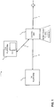
- FIG. 1 illustrates such a database environment 1 at an abstract level.
- Original data hereinafter also referred to as original results
- the first platform 3 is either an original data source itself, such as an inventory database or a database maintaining any kind of original and generally valid results, or accesses one or more original data sources in order to prepare original results. Examples of the latter kind are a search engine accessing Internet websites and a computation platform computing priced travel recommendations based on fares stored in a fare database. If the first platform 3 generates/computes/collects the original results by accessing other/further original data sources in order to prepare original results, the first platform 3 provides results which generally accurately reflect the current content of the original response data . More than one first platform 3 can be present in the database environment 1.
- the database environment 1 further includes a second platform 4 which maintains a pool 5 of results which have been prepared via the first platform 3.
- the second platform 4 is e.g. a cache which caches results having been retrieved via the first platform 3, or the second platform 4 is e.g. a server holding a repository of the content of crawled websites, or the second platform 4 is e.g. a search platform maintaining pre-computed priced travel recommendations, as described by WO 2014/026753 A1 .
- the first platform 3 providing original response data and the second platform 4 maintaining the pool 5 of prepared results differ from each other in technical terms as follows:
- the second platform 4 due to the preparation of the results, provides a cheaper (in terms of computation costs) and/or faster access to the results compared to the first platform 3.
- This relation between the first platform 3 and the second platform 4 can also be expressed the other way around, i.e. the first platform 3 generally responds more slowly and responses from the first platform 3 involve higher computation costs than responses from the second platform 4 because the first platform 3 still has to prepare the results (e.g. retrieve the requested content from the original Internet website, or compute the requested priced travel recommendations on the basis of fares kept in a fare database).
- the number of accesses to the first platform 3 should be kept within a certain limit. For example, CPU consumption or memory load of the first platform 3 must not exceed a given limit. This constraint may be translated into a limit of the number of accesses to the first platform per time unit (e.g. 10 accesses per second). For these reasons, the first platform 3 is not solicited each time in order to respond to data requests. Rather, responses are generally formed by utilizing the prepared results stored in the pool 5 of the second platform 4. In this way, the second platform 4 acts as a shield in front of the first platform 3, thereby reducing the load on the (computationally expensive) first platform 3.
- a limit of the number of accesses to the first platform per time unit e.g. 10 accesses per second.
- the prepared results stored in the pool of the second platform 4 are not necessarily perfectly synchronized with the original results provided by the first platform 3.
- the prepared results of the second platform 4 represent older versions of original result being provided by the first platform 3 and the respective version of the original result provided by the first platform 3 might have changed since the last update of the corresponding prepared result maintained in the second platform 4.
- the second platform 4 does not necessarily store prepared results corresponding to all existing original results, i.e. prepared results might be missing in the second platform 4.
- Prepared results stored in the pool 5 of the second platform 4 which correctly reflect their corresponding result provided by the first platform are hereinafter referred to as valid prepared results or as accurate prepared results, while outdated prepared results stored in the pool 5 of the second platform 4 are referred to as invalid prepared results or inaccurate prepared results.
- the technical problem arises to maximize the accuracy and validity of the prepared results stored in the pool 5 of the second platform 4 and the accuracy and validity of prepared results returned to inquiring clients, respectively, i.e. to maintain prepared results in the second platform 4 that are consistent with the original response data provided by the first platform 3 as much as possible, in order to respond to data request with a high portion of valid prepared results.
- the database environment 1 is further coupled to at least one, but generally a plurality of clients 6.
- Clients 6 such as applications on user terminals retrieve results from the database environment 1 by directing data requests to the database environment 1 via an interface 7.
- the technical characteristics of the interface 7 depend on the particular implementation of the database environment 1.
- the interface 7 encompasses wireless communication including 2G/3G/4G (including packet-oriented mobile data exchange as well as SMS) and/or WiFi communication in the case the client 6 is situated on a mobile communications device.
- the interface 7 features wired communication using standard network protocols employed in local area networks and/or wide area networks including the Internet such Ethernet, TCP/IP, SMTP with POP3 or IMAP, HTTP, webservice-related protocols such as SOAP, etc.
- a data request transmitted from a client 6 via interface 7 includes one or more retrieval criteria constraining the request.
- the data request is an Internet search request
- the data request might carry a search string, search text or search phrase as search criteria.
- a further search criterion may be the language of websites to be searched or an indication of a point of time of the first availability of the requested search string, search text or search phrase.
- the data request is a database request for a product or service offered by a service provider platform such as an Internet book store or a travel provider.
- the data request might include e.g. an upper price limit or a price range for the service or product and desired characteristics of the product/service such as book title, travel origin and destination, etc.
- Data requests issued by a client 6 are received by a further entity of the database environment 1, the control unit 2 ( FIG. 1 ).
- the control unit 2 processes incoming data requests in order to device whether response results are retrieved from the second platform 4 and/or the first platform 3.
- the control unit functions as an intermediate unit controlling the data flow within the database environment 1 and the results to be returned to the client 6.
- controlling the data flow by the control unit 2 takes into account the two following aspects:
- retrieving prepared results fulfilling the request criteria included in a data request from the pool 5 of the second platform 4 has the advantage of a faster response time (compared to generating the results by the first platform 3) and relieves the first platform 3 from potential overloads.
- serving a data request by retrieving original results provided by the first platform 3 allows to update the respective prepared results maintained in the pool 5 of the second platform 4.
- a portion of results to be returned in response a data requests can be intentionally retrieved from the first platform 3, although corresponding prepared results are available in the second platform 4.
- the technical problem is then to decide which portions of the data requests being transmitted from the clients 6 to the control unit 2 are to be responded on the basis of the pool 5 of the second platform 4 and which portions of the data requests are to be responded on the basis of the first platform 3 in order to update the prepared results maintained in the pool 5 of the second platform 4.
- the control unit 2 utilizes an update indicator which is associated with each prepared result maintained in the pool 5 of the second platform 4.
- the update indicator is a measure whether or not the associated prepared result kept in the pool 5 of the second platform 4 needs to be updated.
- the update indicator is defined by (1 - acc) ⁇ t (cf. FIG. 1 ), wherein acc is a probability that the associated prepared result is valid and t is an age of the associated prepared result.
- a given prepared result i kept in the pool 5 of the second platform 4 can be specified by the following parameters:
- the validity probability of the prepared results stored in the pool 5 of the second platform 4 can be defined as follows:
- the validity probability of the prepared results in the pool 5 of the second platform 4 from the perspective of the clients 6 (also referred to as "user accuracy") is then defined in that each validity probability value is weighted by the popularity of the respective prepared result.
- the proportion of probably accurate client accesses to the prepared results as opposed to the expected proportion of accurate prepared results is:
- the update indicator utilized by the control unit 2 to decide whether to return prepared results maintained in the pool 5 of the second platform 4 or whether to retrieve updated prepared results from the first platform 3 in order to both, return the updated results to the requesting client 6 as well as update the respective prepared results in the pool 5 of the second platform 4 thereby increasing the validity of the prepared results in the second platform 4 is formed by these parameters assigned to each of the prepared results in the second platform 4.
- the update indicator described herein is given by (1 - acc) ⁇ t, for a particular prepared result i by (1 - acc i ) ⁇ t i .
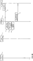
- control unit 2 employs the update indicator as follows (see FIG. 2A and FIG. 2B ).
- the control unit 2 receives a data request 30 from a client 6. Then, the control unit 2 determines at least one prepared result corresponding to the data request 30 (activity 31). Thus, the control unit 2 processes the data request 30, determines the data retrieval criteria included in the data request 30 (examples have already been given above) and identifies a number of prepared results which fulfill the data retrieval criteria. The specific manner how these prepared results fulfilling the data retrieval criteria are identified by the control unit 2 depends on the architecture of the database environment 1 (a particular example is given further below with reference to FIGS. 4 and 5 ). For example, in the case of the data request 30 being an SQL query, the control unit 2 determines the query parameters indicated the SQL query and retrieves identification information identifying prepared results (e.g. primary key values) fulfilling the query parameters of the SQL query from the second platform 4 or another module existing within the database environment 1 for that purpose.
- the control unit 2 determines the query parameters indicated the SQL query and retrieves identification information identifying prepared results (e.g. primary key values) fulfilling the query parameters of the
- This determination of prepared results fulfilling data retrieval criteria of the data request 30 does not necessarily include a retrieval of the content of the prepared results, yet. Rather, it is sufficient to identify these prepared results e.g. on unique identifiers such as their primary key values. In some embodiments, however, activity 31 already encompasses retrieval of the content of the prepared results fulfilling data retrieval criteria of the data request 30 from the second platform 4.
- control unit 2 compares the update indicators of the determined prepared results with a threshold value (activity 32 in FIG. 2A and FIG. 2B ).
- this activity 32 involves a determination of the update indicator values of each of the determined prepared result.
- the control unit 2 e.g. retrieves respective control data such as the timestamps of the last update of the determined prepared results e.g. from a control database, calculates the ages t of the determined prepared results, retrieves the validity rates being associated with the determined prepared results, calculates the validity probability acc of the determined prepared results and then computes (1 - acc) ⁇ t for each of the determined prepared results. The computed values for the update indicator of the determined results are then compared to the threshold value.
- the threshold value controls the amount of prepared results which are updated via the first platform 3 in response to receiving data requests 30 and the complimentary amount of prepared results which are not updated in response to receiving data requests 30, but returned to the client 6 from the pool 5 of the second platform 4.
- the comparison either indicates a need to update the respective prepared result if the update indicator value exceeds the threshold or the comparison indicates that the respective prepared result does not need to be updated if the update indicator value does not exceed the threshold (for reasons of simplicity, we here assume that the comparison yields the same indications for all of the determined prepared results - in practice, the comparison may also indicate that a portion of the determined prepared results should be updated and the remaining portion of the determined prepared results do not need to be updated; this situation is explained further below with reference to FIGS. 6A and 6B and is also applicable to any other examples described herein).
- the control unit 2 retrieves updated versions of the determined prepared results from the first platform 3 (e.g. by relaying the data request to the first platform 3) (message 34 in FIG. 2A ).
- the first platform 3 prepares the updated versions of the prepared results and returns these updated versions of the prepared results to the control unit 2.
- the control unit 2 receives the updated versions of the prepared results from the first platform 3 by message 35.
- the control unit 2 updates the determined prepared search result in the pool 5 of the second platform 4 (activity 36 in FIG. 2A ).
- the control unit 2 also updates the update indicator values associated with the determined prepared results (also activity 36 in FIG.
- control unit 2 returns the updated version of the determined prepared results to the client 6 by message 37.
- activities 36 and 37 may also occur in a different order, i.e. the control unit 2 first returns the prepared results to the client 6 and then updates the prepared results in the second platform and the associated update indicators.
- control unit 2 returns the determined prepared results to the client 6 by message 39, without updating the prepared results by inquiring the first platform 3.
- the present inventors have recognized that repeatedly updating such prepared results having a higher validity rate ⁇ i which are regularly outdated by a change of their corresponding underlying original response data or updating such prepared results that yield promote the user accuracy as defined above is non-optimal.
- Also focusing on updating prepared results with the best gain-cost ratio being e.g. defined as p i 1 ⁇ acc i c i is likewise non-optimal.
- the present inventors have realized that these strategies only yield short-term increases of the prepared results' accuracy, but might cause an accuracy degradation of the pool 5 in the long run.
- the update indicator as proposed herein provides a long-term accuracy increase of the prepared results stored in the second platform 4 by establishing a decision metric to either respond to a data request either with prepared results updated by the first platform 3 (which at the same time update the corresponding prepared results in the second platform 4) or to respond to a data request either with non-updated prepared results being held in the second platform 4 without inquiring the first platform 3 and updating these prepared results in the second platform 4.
- the long-term accuracy increase effect of the update indicator proposed herein will become apparent to the skilled person from the following explanations.
- 1 t i is considered as a potential long-term update frequency of the prepared result i.
- the ratio c i t i can be used as an estimation of the long-term update costs of a given prepared result i.
- a long-term accuracy optimization of the prepared result stored in the pool 5 of the second platform 4 should therefore update the prepared results with the highest 1 ⁇ acc i c i t i
- This definition of the update indicator can still be generalized when assuming that the update cost c i is equal and constant for all prepared results and the update costs constraint is e.g. only employed to limit the number of updates of prepared results per unit of time via the first platform 3.
- the factor c i can be removed from the update indicator resulting in the definition of the update indicator as introduced above, i.e.. 1 ⁇ acc i ⁇ t i
- this update indicator is possible, e.g. when additionally considering the popularity of prepared results, i.e. the user accuracy: p i 1 ⁇ acc i c i t i or p i 1 ⁇ acc i ⁇ t i
- This results in more specific version of the update indicator definitions namely 1 ⁇ e ⁇ ⁇ i t i t i or 1 ⁇ e ⁇ ⁇ i t i c i t i or p i 1 ⁇ e ⁇ ⁇ i t i or p i 1 ⁇ e ⁇ i t i c i t i
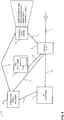
- FIG. 4 present a more specific example of a database environment 1.
- This example differs from the more general architecture shown by FIG. 1 in that it includes certain additional components, namely the control data store 10 and the predictive model manager 12.
- the control data store 10 is connected to the control unit 2 via interface 11 and to the predictive model manager via interface 15.
- the predictive model manager is connected to the first platform 3 via interface 13, to the control unit 2 via interface 14 and to the control data store via interface 15.
- control data store 10 stores data to compute the update indicator for given prepared results stored in the pool 5 of the second platform 4.
- the control data store 10 stores timestamps indicating the last update time of the prepared results in order to compute the age t i at a given point of time.
- the control data store 10 further stores additional control data utilized to determine the values of the various examples of the update indicator as described above, e.g.
- control data kept by the control data store 10 is associated with the prepared results stored maintained in the pool 5 of the second platform 4.
- the control data stored 10 also stores identification information of the prepared results in order to associate the control data with the prepared results.
- a database record of the control data store 10 is defined as follows:
- the identification of the prepared results utilized in the control data store 10 is, for example, the primary key values of the prepared results as stored in the pool 5 of the second platform 4.
- control data store 10 is an integrated part of the control unit 2. In other embodiments, the control data store 10 is an integrated part of the second platform 4. In this case, the control data maintained by the control data store 10 is e.g. stored in a database table being associated with the database table(s) of the prepared results in the pool 5. In still other embodiments, the control data store is a stand-alone component (e.g. realized by a dedicated server system).
- the predictive model manager 12 is arranged to update certain control data stored by the control data store, such as the validity rates ⁇ i , the popularity p i , and the update costs c i .
- the predictive model manager 12 receives input data from the first platform 3 and from the control unit 2. More specifically, the first platform 3 transmits information about the updated prepared results (the updates occurring in response to messages 34 ( FIG. 2A )) to the predictive model manager 12, i.e. which results have been updated at which time and whether or not the updates led to a different content of the updated results.
- the first platform 3 also transmits information regarding the computation costs to update prepared results to the model manager 12 (these information are determined by the first platform itself by monitoring the updates of the various prepared results and the update costs involved and/or from log information received from an original source of the prepared results such as webservers).
- the control unit 2 transmits information about incoming data requests 30 and the prepared results requested by the data requests 30 to the predictive model manager 12, e.g. which prepared results were returned to inquiring clients at which times.
- this input communication from the first platform 3 and/or from the control unit 2 to the predictive model manager 12 occurs asynchronously from processing and serving data requests 30 as visualized by FIGS. 2A , 2B , 5A , 5B , 6A and 6B .
- the first platform 3 transmits the information about an updated prepared result to the predictive model manager 12 synchronously with the update, e.g. immediately after the first platform 3 has returned the updated result to the control unit 2.
- the control unit 2 may transmit the information about incoming data requests 30 and respective returned results to clients 6 to the predictive model manager 12 synchronously with the processing of the data requests 30, e.g. immediately after the control unit 3 has returned the corresponding results to the inquiring client 6.
- the predictive model manager 12 processes these inputs from the first platform 3 and the control unit 2 and provides current control information resulting from the processing to the control data store 10. More specifically, the predictive model manager 12 utilizes the information about the updated prepared results received from the first platform 3, encompassing at least the information whether or not an update of a prepared result by the first platform led to a change of the content of the prepared result and a timestamp of the update, to maintain validity rates ⁇ i for each of the prepared results stored in the pool 5 of the second platform 4. The predictive model manager 12 utilizes the information about the computational costs received from the first platform 3 to maintain the parameters c i for each prepared result i stored in the pool 5 of the second platform 4.
- the predictive model manager 12 utilizes the information about the incoming data requests 30 received from the control unit 2 and correspondingly requested prepared results in order to maintain the popularity values p i for each of the prepared results stored in the pool 5 of the second platform 4.
- the resulting current values of ⁇ i , p i and/or c i are transmitted from the predictive model manager to the control data store 10 and are thus made available to the control unit 2 in order to determine the update indicator values in the course of processing incoming data requests 30 (activity 31).
- Updates of the current values of ⁇ i , p i and/or c i are sent by the predictive model manager 12 to the control data store in regular intervals and/or on demand, i.e. when values of control data have been changed.
- the predictive model manager 12 and/or the control data store 10 employ a distributed batch framework utilizing e.g. Apache Hadoop® enabling both components to execute intensive computing processes with large amounts of data (e.g. in the order of PetaBytes) on server clusters.
- a distributed batch framework utilizing e.g. Apache Hadoop® enabling both components to execute intensive computing processes with large amounts of data (e.g. in the order of PetaBytes) on server clusters.
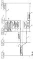
- FIGS. 5A and 5B Exemplary message sequences occurring in the exemplary architecture of FIG. 4 are shown by FIGS. 5A and 5B . Similar to FIGS. 2A and 2B , FIG. 5A shows the variant in which the update indicator values of the prepared results to be returned to the client 6 indicate a need to update the prepared results and FIG. 5B shows the variant in which the update indicator values of the prepared results to be returned to the client 6 do not indicate a need to update the prepared results.
- the process begins with a transmission of a data request 30 from the client 6 to the control unit 2.
- the control unit 2 determines identification information (e.g. primary key values) of prepared results which fulfill criteria included in the data request 30 and associated update indicator values (activity 31A).
- identification information e.g. primary key values
- the data request 30 requests the number of available seats in the flight LH123 on 1 st July 2015.
- the control unit 2 utilizes the key "LH123-1JUL15" already included in the request to retrieve the last update time of the prepared result LH123-1JUL15-42 (i.e.
- the prepared result indicates 42 free seats, wherein the number 42 of available seats is not known to the control unit 2 at that stage) and the validity rate ⁇ LH123-1JUL15 from the control data store 10.
- the control data store 10 responds with respective values of the update timestamp and validity rate ⁇ LH123-1JUL15 (activity 31B in FIG. 5A and 5B ).
- the control unit 2 calculates the update indicator of the prepared result LH123-1JUL15-42 (activity 31C in FIG. 5A and FIG. 5B ) by calculating the age t LH123-1JUL15 (last update timestamp of LH123-1JUL15-42 minus current time) and then calculating (1 - e - ⁇ i t i ) t i .
- the control unit 2 then performs the comparison of the calculated update indicator value with the threshold value (activity 32 in FIG. 5A and FIG. 5B ). If the comparison indicates a need to update the LH123-1JUL15-42 (box 33 in FIG. 5A ), the control unit 2 retrieves an updated version of the prepared result from the first platform 3 (activity 34 in FIG. 5A ).
- the first platform itself is an original inventory of available flight seats and returns the update value (e.g. LH123-1JUL15-23, i.e. 23 free seats) to the control unit 2 on the basis of its own inventory data.
- the first platform 3 retrieves the requested current available seat information from further sources and returns the updated prepared result LH123-1JUL15-23 to the control unit 2 afterwards (activity 35 in FIG. 5A ).
- the control unit 2 after having received the updated prepared result from the first platform 3, returns the updated prepared result to the client 6 (activity 37 in FIG. 5A ), updates the prepared result in the pool 5 of the second platform 4 (e.g. by replacing the previous outdated value 42 with the updated, current value 23, activity 36A) and also updates the last update timestamp of LH123-1JUL15 in the control data store 10 (activity 36B). Note that activities 36A, 36B and 37 may occur in any order.
- the comparison between the current update indicator value of LH123-1JUL15 and the threshold conducted by control unit 2 indicates that an update of LH123-1JUL15 is not necessary (box 38 in FIG. 5B ).
- the control unit 2 retrieves the value of LH123-1JUL15 (e.g. 42 available seats) from the pool 5 of the second platform 4 (activity 40A in FIG. 5B ) and returns this value as a response to data request 30 to the client 6 (activity activity 39).
- activity 31 is more complex ( FIGS. 6A and 6B ) e.g. because the key values of the prepared results in which the client 6 is interested are not included in the data request 30 and, thus, a search may be required to determine which prepared results fulfill the search criteria included in the data request 30.
- the prepared results stored by the pool 5 specify pre-computed priced travel recommendations and the data request 30 e.g. asks for the cheapest travels between Frankfurt and Boston with a departure between 1 st July 2015 and 10 th July 2015 and a stay duration between 11 and 15 days.
- the control unit 2 first identifies prepared results stored in the pool 5 of the second platform 4 which fulfill search criteria of the data request 30.
- activity 31A ( FIG. 6A ) is an inquiry of the control unit 2 to the second platform 4 in order to retrieve identification information of prepared results complying with the search criteria included in the data request 30.
- the second platform 4 e.g. returns all travel recommendations stored in the pool 5 for travels between Frankfurt and Boston with a departure between 1 st July 2015 and 10 th July 2015 and a stay duration between 11 and 15 days (activity 31B in FIG. 6A ).
- the control unit 2 determines the update indicator values for all identified prepared results in the manner described above (retrieving the respective control data from the control data store 10 by activities 31C and 31D in FIG. 6A and calculating the update indicator values by activity 31E in FIG. 6A ) and performs the comparison between update indicator value and threshold for each identified prepared result (activity 32 in FIG. 6A ). For all prepared results for which the comparison indicates a need to update the respective prepared result (box 33 in FIG. 6A ), the control unit 2 retrieves an updated version of the respective prepared result from the first platform 3 (activities 34 and 35 in FIG. 6B ).
- the control unit 2 retrieves the content of these not-to-be-updated prepared results from the second platform 4 (activities 40A and 40B in FIG. 6B ; this applies if the control unit 2 has not already retrieved the content of all the prepared results fulfilling the search criteria with activities 31A and 31B beforehand).
- the control unit 2 stores the updated prepared results in the pool 5 of the second platform 4 (activity 36A in FIG. 6B ), updates the update timestamps of the updated prepared results in the control data store 10 (activities 36B in FIG.
- the prepared results retrieved from the second platform 4 and the updated versions of the prepared results retrieved from the first platform 3 optionally post-processes the prepared results retrieved from the second platform 4 and the updated versions of the prepared results retrieved from the first platform 3 (activity 41 in FIG. 6B ), which is e.g. a determination of a subset of prepared results out of the updated prepared results and the not-updated prepared results determined before to be returned to the client 6 (in the above example, selecting the most inexpensive travel recommendation), and returns these results to the client 6 (activity 37 in FIG. 6B ).
- activity 41 in FIG. 6B is e.g. a determination of a subset of prepared results out of the updated prepared results and the not-updated prepared results determined before to be returned to the client 6 (in the above example, selecting the most inexpensive travel recommendation), and returns these results to the client 6 (activity 37 in FIG. 6B ).
- still different message flows are employed, depending on the particular characteristics of the database model(s) employed by the database environment 1 and structure and criteria included in the data requests 30.
- post-processing of prepared results (activity 41 in FIG. 6A ) is not employed, but all the prepared results retrieved from the second platform 4 and all updated versions of the prepared results retrieved from the first platform 3 are returned to the client 6.
- the prepared results retrieved from the second platform 4 are already returned to the client 6 as soon as they are available (activity 39 in FIG.
- activity 37 of FIG. 6B then only encompasses returning the updated versions of the prepared results retrieved from the first platform 3.
- the message flow shown in FIGS. 6A and 6B is also adapted in that the post-processing activity 41 is performed already at an earlier stage, for example by the control unit 2 after having received the content of the prepared results with activity 31B or by the second platform 4 before returning the prepared results (or at least their identities) with activity 31B.
- the second platform 4 is arranged to determine a limited number of the most inexpensive travel recommendations for travels between Frankfurt and Boston with a departure between 1 st July 2015 and 10 th July 2015 and a stay duration between 11 and 15 days (as opposed to returning all priced travel recommendations for travels between Frankfurt and Boston with a departure between 1 st July 2015 and 10 th July 2015 and a stay duration between 11 and 15 days stored in the pool 5).
- the second platform 4 returns only the five cheapest travel recommendations.
- the subsequent activities of the control unit 2 (activities 31C, 31D, 31E, 32-38) are then limited to only these five retrieved prepared results and are performed in the same manner as described above.
- the threshold value is dynamically adapted depending on the load of the first platform 3. In this way, by using the adaptive threshold value, the amount of prepared results which are updated via the first platform 3 and therefore the load of the first platform are controlled. If the load of the first platform 3 is too high (too many prepared results are updated via the first platform 3 in a given time unit) and the load is to be reduced, the threshold value is increased with the effect that the portion of prepared results which are updated via the first platform 3 is decreased and the portion of prepared results which are retrieved from the second platform 4 and returned to the client 6 without update is increased.
- the threshold value is decreased with the effect that the portion of prepared results which are updated via the first platform 3 is increased and the portion of prepared results which are retrieved from the second platform 4 and returned to the client 6 without update are decreased.
- dynamically adapting the threshold value is realized by maintaining a feedback control loop 20 between the first platform 3 and the control unit 2 ( FIG. 7 ).
- the feedback control loop 20 is defined by three variables, namely the control value 21, the setpoint 18 and the actuating variable 19.
- the control value 21 is the variable to be controlled (to be kept constant at a given target level) and is therefore defined by a current actual load factor of the first platform 3.
- the setpoint 18 of the feedback control loop 20 is given by a desired target load factor of the first platform 3.
- the actuating variable of the feedback control loop 20 is the threshold value which impacts the actual load factor of the first platform, i.e. controls the control value 21.
- the feedback control loop 20 is realized by the first platform 3 and the control unit 2 communicating with each other in regular intervals as follows.
- the threshold value is decreased by N/B%, resulting in a higher amount of prepared results being updated with the first platform 3 and, thus, increasing the current actual load factor 21.
- FIG. 8 is a diagrammatic representation of a computer system which provides the functionality of the control unit 2.
- the control unit 2 includes a processor 81, a main memory 82 and a network interface device 83, which communicate with each other via a bus 84.
- the control unit 2 further includes a static memory 85 and a disk-drive unit 86.
- a video display 87, an alpha-numeric input device 88 and a cursor control device 89 may form a user interface for e.g. an administrator to control the control unit 2.
- the network interface device 83 connects the control unit 2 to the first platform 3 via the interface 9 and to the second platform 4 via the interface 8.
- the network interface device 83 also connects the control unit 2 to the clients 6 via interface 7.
- a set of instructions (i.e. software) 90 embodying any one, or all, of the methods described above, resides completely, or at least partially, in or on a machine-readable medium, e.g. the main memory 82 and/or the processor 81.
- a machine-readable medium on which the software 90 resides may also be a non-volatile data carrier (e.g. a non-removable magnetic hard disk or an optical or magnetic removable disk) which is part of disk drive unit 86.
- the software 90 may further be transmitted or received as a propagated signal e.g. via the Internet or any other network through the network interface device 83.
- Basic operation of the control unit 2 including user interface and network communication is controlled by operating system 91.
- the present approach to control routing of incoming data requests by the control unit to the first platform and or to the second platform on the basis of the update indicator (1 - acc) ⁇ t being compared with the threshold value provides an improved the long-term validity of prepared results maintained in the pool of the second platform.
- This approach allows to optimally determine which prepared results to be returned in response to data requests are to be retrieved from the first platform and thereby updated in the second platform. In this way, an ineffective focus on repeatedly updating very volatile prepared result is avoided, thereby improving the accuracy/validity of the prepared results in the long run.
Landscapes
- Engineering & Computer Science (AREA)
- Databases & Information Systems (AREA)
- Theoretical Computer Science (AREA)
- Computational Linguistics (AREA)
- Data Mining & Analysis (AREA)
- Physics & Mathematics (AREA)
- General Engineering & Computer Science (AREA)
- General Physics & Mathematics (AREA)
- Information Retrieval, Db Structures And Fs Structures Therefor (AREA)
Description
- The present invention generally relates to database technology. More specifically, it is directed to a mechanism for handling incoming data requests considering the accuracy of prepared results to be returned to a data request.
- A common problem in database technology is to ensure short response times to database queries or requests which require complex, long and resource-intensive processing, e.g. due to large volumes of data. For example, such computing-power consuming processing has to be performed in response to so-called "open queries" which contain only little input information (e.g. only one or two parameters out of a dozen possible parameters are specified and/or the specified value ranges of the parameters are broad) and, consequently, lead to a large number of results in general. Possibilities to speed up data processing by increasing hardware performance are limited. Thus, attention is drawn to improving the mechanisms underlying the complex, long and resource-intensive processing in order to respond to such queries.
- One general approach to shorten response times is to prepare results to be returned in response to expected requests (e.g. by pre-computing or pre-collecting such results) and to maintain the corresponding query results in a pool of prepared results. Requests are then actually not processed and responses on the basis of the large original data basis, but are directed to the pool of prepared results.
- Another issue, however, which comes along with such result preparing approaches, is to keep the prepared results up-to-date in order to ensure that prepared results returned in response to data requests correctly reflect the outcome of a complex, long and resource-intensive processing. In case the underlying original data basis changes, the prepared results get outdated and answering requests on the basis of the pool of prepared results would deliver incorrect prepared results. Thus, update strategies are employed to keep the pool of prepared results up-to-date.
- Various relatively simple update strategies are known in the prior art like, for example, re-computing the entire domain of prepared results frequently, establishing and maintaining re-computation schedules manually and re-computing prepared results when they are getting too old.
- Somewhat more sophisticated update strategies have been developed, as e.g. described by
WO 01/33472 WO 02/25557 -
WO 01/33472 - Similarly,
WO 02/25557 - Moreover,
WO 99/22315 -
US2009/0204753 A1 relates to refreshing a cache based on query responses provided by a searching system in response to queries. A cache entry is provided for each unique query if space is available in the cache. A temperature value is assigned to each cache entry based on a frequency of occurrence of the corresponding query. An age value is assigned to each cache entry based on a time of last refresh or creation of the corresponding query response. The age of the cache entries is periodically updated and the temperature of a cache entry is updated when a corresponding query occurs. If system resources are available, the query response of a cache entry is refreshed based on the temperature and age of the cache entry. Refreshing is limited if resources are unavailable. - The article "Synchronizing a database to Improve Freshness" by J. Cho et al. studies possibilities to refresh a local copy of an autonomous data source to maintain the copy up-to-date. Inter alia, the Poisson process is described as an approach to model the probabilistic evolution of an element.
- The present invention is defined by the independent claims.
- According to one aspect, a method for handling data requests directed to a database environment is provided. The database environment has a least one first platform providing original results to be stored in a second platform as prepared results. The second platform maintains a pool of the prepared results having been prepared via the first platform in order to be returned to data requests. The database environment further has a control unit for processing the data requests directed to the database environment. Each prepared result maintained in the pool of the second platform is associated with an update indicator being a measure that the associated prepared resuit kept in the pool of the second platform is to be updated. The control unit receives a data request. The control unit determines at least one prepared result corresponding to the data request. The control units compares the update indicator of the determined prepared result corresponding to the data request with a threshold value, wherein the threshold value is dynamically adapted depending on the load of the first platform. If the comparison indicates a requirement to update the prepared result, the control unit retrieves an updated version of the at least one prepared result from the first platform. The control unit updates the prepared result in the pool of the second platform and the associated update indicator based on the updated version of the at least one prepared result. The control unit returns the updated version of the at least one result. On the other hand, if the comparison does not indicate a requirement to update the at least one prepared result, the control unit returns the at least one determined prepared result. The update indicator is defined by

- According to a second aspect, a control unit being arranged accordingly is provided.
- According to a third aspect, a computer program to be executed by a control unit and enabling the control unit with respective functionality is provided.
- Further aspects are defined by the dependent claims.
- The subsequent description of embodiments is based on the accompanying set of figures in which similar reference numerals refer to similar elements and messages and in which:
-
FIG. 1 shows a high-level schematic overview of the system architecture as described herein; -
FIGS. 2A and2B depict a high-level message flow for processing data requests by utilizing update indicators; -
FIG. 3 represents an effect of decreasing validity probability of prepared results; -
FIG. 4 presents an exemplary system architecture of the database environment; -
FIGS. 5A and5B depict a more specific message flow example for processing data requests by utilizing update indicators; -
FIG. 6A and6B depict another message flow example for processing data requests by utilizing update indicators; -
FIG. 7 visualizes a feedback loop between the first platform and the control unit in order to dynamically adapt the threshold value; -
FIG. 8 shows an example for an inner structure of a control unit. - Before turning to the description of the embodiments on the basis of
FIG. 4 to 8 , a few more general aspects are elaborated first with reference toFIG. 1 to 3 . - As already outlined at the outset, the methodologies described herein relate to database systems which offer prepared results to clients requesting data from a database system. The technical aim of preparing results before they are requested from clients is generally to decrease response times for responding to such data requests. Hereinafter, the term "prepared" is used to relate any sort of pre-processing, pre-computation and pre-collection of results in an asynchronous manner, i.e. independently from and prior to a data request from a client. Examples for a preparation of results are Internet crawlers collecting or copying the content of Internet web servers as well as results generated in response to earlier data requests that are maintained in a cache for fast retrieval, but also complex and time-intensive computations of search results on the basis of underlying data as it is e.g. described for priced travel recommendations by
PCT/EP2013/002390 EP 2541473 A1 . The term "database" is meant to encompass any types of structured information storage system such as standard stand-alone databases like SQL server or Oracle databases as well as complex, distributed and/or proprietary storage systems, relational databases including database management systems or object-oriented database systems and the like. The term "data request" is used herein as a general term for any types of inquiries to a database system in order to retrieve data including any type of information retrieval requests such as transactional queries, requests for batch computations, SQL queries and other forms. -
FIG. 1 illustrates such adatabase environment 1 at an abstract level. Original data, hereinafter also referred to as original results, are provided by afirst platform 3. In general, thefirst platform 3 is either an original data source itself, such as an inventory database or a database maintaining any kind of original and generally valid results, or accesses one or more original data sources in order to prepare original results. Examples of the latter kind are a search engine accessing Internet websites and a computation platform computing priced travel recommendations based on fares stored in a fare database. If thefirst platform 3 generates/computes/collects the original results by accessing other/further original data sources in order to prepare original results, thefirst platform 3 provides results which generally accurately reflect the current content of the original response data . More than onefirst platform 3 can be present in thedatabase environment 1. - The
database environment 1 further includes asecond platform 4 which maintains apool 5 of results which have been prepared via thefirst platform 3. Thesecond platform 4 is e.g. a cache which caches results having been retrieved via thefirst platform 3, or thesecond platform 4 is e.g. a server holding a repository of the content of crawled websites, or thesecond platform 4 is e.g. a search platform maintaining pre-computed priced travel recommendations, as described byWO 2014/026753 A1 . - In general, the
first platform 3 providing original response data and thesecond platform 4 maintaining thepool 5 of prepared results differ from each other in technical terms as follows: Thesecond platform 4, due to the preparation of the results, provides a cheaper (in terms of computation costs) and/or faster access to the results compared to thefirst platform 3. This relation between thefirst platform 3 and thesecond platform 4 can also be expressed the other way around, i.e. thefirst platform 3 generally responds more slowly and responses from thefirst platform 3 involve higher computation costs than responses from thesecond platform 4 because thefirst platform 3 still has to prepare the results (e.g. retrieve the requested content from the original Internet website, or compute the requested priced travel recommendations on the basis of fares kept in a fare database). As the computation resources of thefirst platform 3 are limited, the number of accesses to thefirst platform 3 should be kept within a certain limit. For example, CPU consumption or memory load of thefirst platform 3 must not exceed a given limit. This constraint may be translated into a limit of the number of accesses to the first platform per time unit (e.g. 10 accesses per second). For these reasons, thefirst platform 3 is not solicited each time in order to respond to data requests. Rather, responses are generally formed by utilizing the prepared results stored in thepool 5 of thesecond platform 4. In this way, thesecond platform 4 acts as a shield in front of thefirst platform 3, thereby reducing the load on the (computationally expensive)first platform 3. - On the other hand, however, the prepared results stored in the pool of the
second platform 4 are not necessarily perfectly synchronized with the original results provided by thefirst platform 3. In general, the prepared results of thesecond platform 4 represent older versions of original result being provided by thefirst platform 3 and the respective version of the original result provided by thefirst platform 3 might have changed since the last update of the corresponding prepared result maintained in thesecond platform 4. Furthermore, thesecond platform 4 does not necessarily store prepared results corresponding to all existing original results, i.e. prepared results might be missing in thesecond platform 4. Prepared results stored in thepool 5 of thesecond platform 4 which correctly reflect their corresponding result provided by the first platform are hereinafter referred to as valid prepared results or as accurate prepared results, while outdated prepared results stored in thepool 5 of thesecond platform 4 are referred to as invalid prepared results or inaccurate prepared results. - Thus, the technical problem arises to maximize the accuracy and validity of the prepared results stored in the
pool 5 of thesecond platform 4 and the accuracy and validity of prepared results returned to inquiring clients, respectively, i.e. to maintain prepared results in thesecond platform 4 that are consistent with the original response data provided by thefirst platform 3 as much as possible, in order to respond to data request with a high portion of valid prepared results. - The
database environment 1 is further coupled to at least one, but generally a plurality ofclients 6.Clients 6 such as applications on user terminals retrieve results from thedatabase environment 1 by directing data requests to thedatabase environment 1 via aninterface 7. The technical characteristics of theinterface 7 depend on the particular implementation of thedatabase environment 1. For example, theinterface 7 encompasses wireless communication including 2G/3G/4G (including packet-oriented mobile data exchange as well as SMS) and/or WiFi communication in the case theclient 6 is situated on a mobile communications device. Alternatively or in addition, theinterface 7 features wired communication using standard network protocols employed in local area networks and/or wide area networks including the Internet such Ethernet, TCP/IP, SMTP with POP3 or IMAP, HTTP, webservice-related protocols such as SOAP, etc. - A data request transmitted from a
client 6 viainterface 7 includes one or more retrieval criteria constraining the request. For example, if the data request is an Internet search request, the data request might carry a search string, search text or search phrase as search criteria. A further search criterion may be the language of websites to be searched or an indication of a point of time of the first availability of the requested search string, search text or search phrase. According to another example, the data request is a database request for a product or service offered by a service provider platform such as an Internet book store or a travel provider. In that case, the data request might include e.g. an upper price limit or a price range for the service or product and desired characteristics of the product/service such as book title, travel origin and destination, etc. - Data requests issued by a
client 6 are received by a further entity of thedatabase environment 1, the control unit 2 (FIG. 1 ). In general, thecontrol unit 2 processes incoming data requests in order to device whether response results are retrieved from thesecond platform 4 and/or thefirst platform 3. To this end, the control unit functions as an intermediate unit controlling the data flow within thedatabase environment 1 and the results to be returned to theclient 6. - Basically, controlling the data flow by the
control unit 2 takes into account the two following aspects: On the one hand, as already explained above, retrieving prepared results fulfilling the request criteria included in a data request from thepool 5 of thesecond platform 4 has the advantage of a faster response time (compared to generating the results by the first platform 3) and relieves thefirst platform 3 from potential overloads. On the other hand, however, serving a data request by retrieving original results provided by thefirst platform 3 allows to update the respective prepared results maintained in thepool 5 of thesecond platform 4. Thus, a portion of results to be returned in response a data requests can be intentionally retrieved from thefirst platform 3, although corresponding prepared results are available in thesecond platform 4. These results are thus newly prepared by thefirst platform 3 and returned to the requestingclient 6 and stored in thepool 5 of thesecond platform 4 thereby updating the corresponding prepared results. - The technical problem is then to decide which portions of the data requests being transmitted from the
clients 6 to thecontrol unit 2 are to be responded on the basis of thepool 5 of thesecond platform 4 and which portions of the data requests are to be responded on the basis of thefirst platform 3 in order to update the prepared results maintained in thepool 5 of thesecond platform 4. - To this end, the
control unit 2 utilizes an update indicator which is associated with each prepared result maintained in thepool 5 of thesecond platform 4. In general, the update indicator is a measure whether or not the associated prepared result kept in thepool 5 of thesecond platform 4 needs to be updated. The update indicator is defined by (1 - acc) · t (cf.FIG. 1 ), wherein acc is a probability that the associated prepared result is valid and t is an age of the associated prepared result. Before turning to the message sequences involved in the processing of and responding to a data request, the nature of the update indicator is elaborated in more detail first. - A given prepared result i kept in the
pool 5 of thesecond platform 4 can be specified by the following parameters: - The age ti of the prepared result i denotes the time since the first preparation or the last update (whichever occurred last) of the prepared result i via the
first platform 3. The age ti can be calculated dynamically at a given point of time by computing the time interval since the last preparation of the prepared result i (current time minus time of last preparation/update). To this end, the timestamp of the most recent preparation of the prepared result is stored in order to compute the age ti of the prepared result i when necessary. - The probability acci that the prepared result i is valid. This probability can be predicted by a probabilistic model modeling the validity behavior of prepared results. An example of such a model is based on a validity rate of a prepared result i which is described next.
- The validity rate λi of the prepared result i is an indicator of how frequently the result i prepared by the
first platform 3 changes and thus how fast the prepared result i stored in thepool 5 of thesecond platform 4 becomes invalid due to changes of the result i provided by the first platform 3 (e.g. due to changes of the data kept by thefirst platform 3 or by changes in data kept by other data sources on the basis of which thefirst platform 3 computes the result i). This validity rate λi of a given prepared result i is, for example, statistically derived from the occurrence and the outcomes of past preparations and updates and comparisons of the updated prepared result i with its previous state or values in order to determine whether the prepared result i with age ti was still valid (its state or value is not changed by the update) or whether the prepared result i with age ti was invalid (its state or value is changed by the update). For example, it has been determined that a particular prepared result i has a validity rate λi of 10% per hour meaning that the probability of i being valid decreases by 10% every hour. At the time of an update of the prepared result i, i is generally 100% valid. After one hour, i is valid with a probability of 90%. After two hours the validity of i is 81% (=90% decreased by another 10%). After three hours, i's probable validity is at 72.9%, and so on. - As mentioned above, the validity rate λi can be employed to provide an estimate of the probability for a prepared result to stay valid after a given time P(unchanged after t) = e-λ
i t which, in some embodiments, is considered to be the probability of a prepared result being valid or, in other words, not being outdated acci = e-λi ti . Two exemplary functions of this probable accuracy decreasing over time are depicted byFIG. 3 .Function 16 represents a prepared result which potentially remains more accurate (or, more correctly, stays at a higher probability of being valid over time) than another prepared result associated withfunction 17. For example, the prepared result represented byfunction 16 has 70% probability of being still valid at 35 hours after its last re-computation, while the other prepared result characterized byfunction 17 is only valid up to about 50% at 35 hours after its latest re-computation.Functions - The popularity pi of the prepared result i is an average access frequency to this prepared result by the
clients 7 viainterface 7. Some embodiments aim at achieving a better accuracy for these prepared results which are more often requested by theclients 6 than other prepared results. - The update cost ci relates to computation resources (such as the amount of CPU time, but also encompassing e.g. network resources required e.g. to collect original response data from other sources as mentioned above) of the first source to update the prepared result i. In some embodiments, indications of ci for different prepared results are available (e.g. from previous updates). In this case, the update cost parameter can be used to favor updating prepared results requiring less computation resources than other prepared results in order to update more prepared results. Otherwise, an assumption can be made that all prepared results have the same update costs. In any case, in some embodiments, the update cost parameter is used to limit the number of updates per time unit to the amount of computing resources available at the
first platform 3, i.e. ∑i updated ci ≤ Resources for each unit of time. - With these parameters, the validity probability of the prepared results stored in the
pool 5 of thesecond platform 4 can be defined as follows:
The validity probability of all prepared results kept in thepool 5 of thesecond platform 4 can be considered as the mean validity, also referred to as "global accuracy", which is defined by
pool 5 of thesecond platform 4. - Now introducing the above-mentioned exemplary probabilistic model based on the validity rate λi, the global accuracy is given by:

- The validity probability of the prepared results in the
pool 5 of thesecond platform 4 from the perspective of the clients 6 (also referred to as "user accuracy") is then defined in that each validity probability value is weighted by the popularity of the respective prepared result. Thus, the proportion of probably accurate client accesses to the prepared results as opposed to the expected proportion of accurate prepared results is:
- The update indicator utilized by the
control unit 2 to decide whether to return prepared results maintained in thepool 5 of thesecond platform 4 or whether to retrieve updated prepared results from thefirst platform 3 in order to both, return the updated results to the requestingclient 6 as well as update the respective prepared results in thepool 5 of thesecond platform 4 thereby increasing the validity of the prepared results in thesecond platform 4 is formed by these parameters assigned to each of the prepared results in thesecond platform 4. In the most basic form, the update indicator described herein is given by (1 - acc) · t, for a particular prepared result i by (1 - acci) · ti. Refined definitions based on this basic form are utilized, such as

- Irrespective which of the aforementioned definitions of the update indicator is utilized, the
control unit 2 employs the update indicator as follows (seeFIG. 2A andFIG. 2B ). - The
control unit 2 receives adata request 30 from aclient 6. Then, thecontrol unit 2 determines at least one prepared result corresponding to the data request 30 (activity 31). Thus, thecontrol unit 2 processes thedata request 30, determines the data retrieval criteria included in the data request 30 (examples have already been given above) and identifies a number of prepared results which fulfill the data retrieval criteria. The specific manner how these prepared results fulfilling the data retrieval criteria are identified by thecontrol unit 2 depends on the architecture of the database environment 1 (a particular example is given further below with reference toFIGS. 4 and5 ). For example, in the case of thedata request 30 being an SQL query, thecontrol unit 2 determines the query parameters indicated the SQL query and retrieves identification information identifying prepared results (e.g. primary key values) fulfilling the query parameters of the SQL query from thesecond platform 4 or another module existing within thedatabase environment 1 for that purpose. - This determination of prepared results fulfilling data retrieval criteria of the
data request 30 does not necessarily include a retrieval of the content of the prepared results, yet. Rather, it is sufficient to identify these prepared results e.g. on unique identifiers such as their primary key values. In some embodiments, however,activity 31 already encompasses retrieval of the content of the prepared results fulfilling data retrieval criteria of the data request 30 from thesecond platform 4. - Further on, the
control unit 2 compares the update indicators of the determined prepared results with a threshold value (activity 32 inFIG. 2A andFIG. 2B ). At a more detailed level, thisactivity 32 involves a determination of the update indicator values of each of the determined prepared result. To this end, thecontrol unit 2 e.g. retrieves respective control data such as the timestamps of the last update of the determined prepared results e.g. from a control database, calculates the ages t of the determined prepared results, retrieves the validity rates being associated with the determined prepared results, calculates the validity probability acc of the determined prepared results and then computes (1 - acc) · t for each of the determined prepared results. The computed values for the update indicator of the determined results are then compared to the threshold value. - The threshold value controls the amount of prepared results which are updated via the
first platform 3 in response to receivingdata requests 30 and the complimentary amount of prepared results which are not updated in response to receivingdata requests 30, but returned to theclient 6 from thepool 5 of thesecond platform 4. - The comparison either indicates a need to update the respective prepared result if the update indicator value exceeds the threshold or the comparison indicates that the respective prepared result does not need to be updated if the update indicator value does not exceed the threshold (for reasons of simplicity, we here assume that the comparison yields the same indications for all of the determined prepared results - in practice, the comparison may also indicate that a portion of the determined prepared results should be updated and the remaining portion of the determined prepared results do not need to be updated; this situation is explained further below with reference to
FIGS. 6A and6B and is also applicable to any other examples described herein). - In the case the comparison indicates a requirement to update the prepared results (
box 33 inFIG. 2A ), thecontrol unit 2 retrieves updated versions of the determined prepared results from the first platform 3 (e.g. by relaying the data request to the first platform 3) (message 34 inFIG. 2A ). Thefirst platform 3 prepares the updated versions of the prepared results and returns these updated versions of the prepared results to thecontrol unit 2. Thecontrol unit 2 receives the updated versions of the prepared results from thefirst platform 3 bymessage 35. Thecontrol unit 2 then updates the determined prepared search result in thepool 5 of the second platform 4 (activity 36 inFIG. 2A ). In addition, thecontrol unit 2 also updates the update indicator values associated with the determined prepared results (alsoactivity 36 inFIG. 2A ) such as storing the new timestamp of this update of the determined prepared results. Finally, thecontrol unit 2 returns the updated version of the determined prepared results to theclient 6 bymessage 37. Note thatactivities control unit 2 first returns the prepared results to theclient 6 and then updates the prepared results in the second platform and the associated update indicators. - On the other hand, in the case the
comparison 32 does not indicate a requirement to update the determined prepared results (box 38 inFIG. 2B ), thecontrol unit 2 returns the determined prepared results to theclient 6 bymessage 39, without updating the prepared results by inquiring thefirst platform 3. - The above basic definition of the update indicator as being given by (1 - acc) · t encompasses the technical effect of providing an improved validity of the prepared results in the long run, as will be explained next.
- The present inventors have recognized that repeatedly updating such prepared results having a higher validity rate λi which are regularly outdated by a change of their corresponding underlying original response data or updating such prepared results that yield promote the user accuracy as defined above is non-optimal. Such a strategy is, for example, described by
WO 99/22315 
pool 5 in the long run. - On the other hand, the update indicator as proposed herein provides a long-term accuracy increase of the prepared results stored in the
second platform 4 by establishing a decision metric to either respond to a data request either with prepared results updated by the first platform 3 (which at the same time update the corresponding prepared results in the second platform 4) or to respond to a data request either with non-updated prepared results being held in thesecond platform 4 without inquiring thefirst platform 3 and updating these prepared results in thesecond platform 4. The long-term accuracy increase effect of the update indicator proposed herein will become apparent to the skilled person from the following explanations. - As explained above, previously known update strategies focus on updating prepared results which are likely to be invalid, i.e. employ an update indicator of (1 - acci), or refined versions of this such as

first platform 3. Thus, if e.g. the prepared result i is updated twice as often as another prepared result over a longer period of time, the accumulated amount of ci over this longer period of time is twice as high as the accumulated costs for updating the other prepared result during the same period of time. Therefore, the long-term update costs of a prepared result i can be defined by considering the long-term update frequency fi of the prepared result i (e.g. fi = 20 updates of i within 120 hours = 1/6 or fi = 6 updates of i within 120 hours = 1/20)
- Considering these long-term update costs leads to the insight that prepared results should be updated in a way providing the highest accuracy gain at the lowest long-term update costs, i.e. with the highest

data request 30, it is decided to update a given prepared result i which has not been refreshed for a time period of ti, the long-term update frequency of this prepared result i is assumed to be


pool 5 of thesecond platform 4 should therefore update the prepared results with the highest
- This definition of the update indicator can still be generalized when assuming that the update cost ci is equal and constant for all prepared results and the update costs constraint is e.g. only employed to limit the number of updates of prepared results per unit of time via the
first platform 3. In this case, the factor ci can be removed from the update indicator resulting in the definition of the update indicator as introduced above, i.e..
- As also briefly indicated above, further refinements of this update indicator are possible, e.g. when additionally considering the popularity of prepared results, i.e. the user accuracy:


- Furthermore, acci may be replaced by the specifically employed probabilistic model modeling the validity of prepared results decreasing over time, such as acci = e-λ
i ti as deduced further above. This results in more specific version of the update indicator definitions, namely


-
FIG. 4 present a more specific example of adatabase environment 1. This example differs from the more general architecture shown byFIG. 1 in that it includes certain additional components, namely thecontrol data store 10 and thepredictive model manager 12. Thecontrol data store 10 is connected to thecontrol unit 2 viainterface 11 and to the predictive model manager viainterface 15. The predictive model manager is connected to thefirst platform 3 viainterface 13, to thecontrol unit 2 viainterface 14 and to the control data store viainterface 15. - In some embodiments, the
control data store 10 stores data to compute the update indicator for given prepared results stored in thepool 5 of thesecond platform 4. In particular, thecontrol data store 10 stores timestamps indicating the last update time of the prepared results in order to compute the age ti at a given point of time. Optionally, thecontrol data store 10 stores data to model the probability for prepared results maintained in thepool 5 of thesecond platform 4 to be accurate, for example the validity rates λi of the prepared results in order to compute acci = e-λi ti at a given point of time. Optionally, thecontrol data store 10 further stores additional control data utilized to determine the values of the various examples of the update indicator as described above, e.g. the request rate (popularity) pi of the prepared results stored in thepool 5 of thesecond platform 4 and/or the computation costs ci to update prepared results. The control data kept by thecontrol data store 10 is associated with the prepared results stored maintained in thepool 5 of thesecond platform 4. Thus, the control data stored 10 also stores identification information of the prepared results in order to associate the control data with the prepared results. For example, a database record of thecontrol data store 10 is defined as follows: - The identification of the prepared results utilized in the
control data store 10 is, for example, the primary key values of the prepared results as stored in thepool 5 of thesecond platform 4. - In some embodiments, the
control data store 10 is an integrated part of thecontrol unit 2. In other embodiments, thecontrol data store 10 is an integrated part of thesecond platform 4. In this case, the control data maintained by thecontrol data store 10 is e.g. stored in a database table being associated with the database table(s) of the prepared results in thepool 5. In still other embodiments, the control data store is a stand-alone component (e.g. realized by a dedicated server system). - The
predictive model manager 12 is arranged to update certain control data stored by the control data store, such as the validity rates λi, the popularity pi, and the update costs ci. In order to determine current values for these parameters, thepredictive model manager 12 receives input data from thefirst platform 3 and from thecontrol unit 2. More specifically, thefirst platform 3 transmits information about the updated prepared results (the updates occurring in response to messages 34 (FIG. 2A )) to thepredictive model manager 12, i.e. which results have been updated at which time and whether or not the updates led to a different content of the updated results. Thefirst platform 3 also transmits information regarding the computation costs to update prepared results to the model manager 12 (these information are determined by the first platform itself by monitoring the updates of the various prepared results and the update costs involved and/or from log information received from an original source of the prepared results such as webservers). Thecontrol unit 2 transmits information about incoming data requests 30 and the prepared results requested by the data requests 30 to thepredictive model manager 12, e.g. which prepared results were returned to inquiring clients at which times. In some embodiments, this input communication from thefirst platform 3 and/or from thecontrol unit 2 to thepredictive model manager 12 occurs asynchronously from processing and servingdata requests 30 as visualized byFIGS. 2A ,2B ,5A ,5B ,6A and6B . In other embodiments, thefirst platform 3 transmits the information about an updated prepared result to thepredictive model manager 12 synchronously with the update, e.g. immediately after thefirst platform 3 has returned the updated result to thecontrol unit 2. In such embodiments, also thecontrol unit 2 may transmit the information about incoming data requests 30 and respective returned results toclients 6 to thepredictive model manager 12 synchronously with the processing of the data requests 30, e.g. immediately after thecontrol unit 3 has returned the corresponding results to the inquiringclient 6. - The
predictive model manager 12 processes these inputs from thefirst platform 3 and thecontrol unit 2 and provides current control information resulting from the processing to thecontrol data store 10. More specifically, thepredictive model manager 12 utilizes the information about the updated prepared results received from thefirst platform 3, encompassing at least the information whether or not an update of a prepared result by the first platform led to a change of the content of the prepared result and a timestamp of the update, to maintain validity rates λi for each of the prepared results stored in thepool 5 of thesecond platform 4. Thepredictive model manager 12 utilizes the information about the computational costs received from thefirst platform 3 to maintain the parameters ci for each prepared result i stored in thepool 5 of thesecond platform 4. Thepredictive model manager 12 utilizes the information about the incoming data requests 30 received from thecontrol unit 2 and correspondingly requested prepared results in order to maintain the popularity values pi for each of the prepared results stored in thepool 5 of thesecond platform 4. The resulting current values of λi, pi and/or ci are transmitted from the predictive model manager to thecontrol data store 10 and are thus made available to thecontrol unit 2 in order to determine the update indicator values in the course of processing incoming data requests 30 (activity 31). Updates of the current values of λi, pi and/or ci are sent by thepredictive model manager 12 to the control data store in regular intervals and/or on demand, i.e. when values of control data have been changed. - In some embodiments, the
predictive model manager 12 and/or thecontrol data store 10 employ a distributed batch framework utilizing e.g. Apache Hadoop® enabling both components to execute intensive computing processes with large amounts of data (e.g. in the order of PetaBytes) on server clusters. - Exemplary message sequences occurring in the exemplary architecture of
FIG. 4 are shown byFIGS. 5A and5B . Similar toFIGS. 2A and2B ,FIG. 5A shows the variant in which the update indicator values of the prepared results to be returned to theclient 6 indicate a need to update the prepared results andFIG. 5B shows the variant in which the update indicator values of the prepared results to be returned to theclient 6 do not indicate a need to update the prepared results. - In both variants, the process begins with a transmission of a
data request 30 from theclient 6 to thecontrol unit 2. In response to receiving thedata request 30, thecontrol unit 2 determines identification information (e.g. primary key values) of prepared results which fulfill criteria included in thedata request 30 and associated update indicator values (activity 31A). As a simple example, the data request 30 requests the number of available seats in the flight LH123 on 1st July 2015. In response to receiving thisdata request 30, thecontrol unit 2 utilizes the key "LH123-1JUL15" already included in the request to retrieve the last update time of the prepared result LH123-1JUL15-42 (i.e. the prepared result indicates 42 free seats, wherein the number 42 of available seats is not known to thecontrol unit 2 at that stage) and the validity rate λLH123-1JUL15 from thecontrol data store 10. Thecontrol data store 10 responds with respective values of the update timestamp and validity rate λLH123-1JUL15 (activity 31B inFIG. 5A and5B ). Thecontrol unit 2 then calculates the update indicator of the prepared result LH123-1JUL15-42 (activity 31C inFIG. 5A andFIG. 5B ) by calculating the age tLH123-1JUL15 (last update timestamp of LH123-1JUL15-42 minus current time) and then calculating (1 - e-λi ti ) ti. - The
control unit 2 then performs the comparison of the calculated update indicator value with the threshold value (activity 32 inFIG. 5A andFIG. 5B ). If the comparison indicates a need to update the LH123-1JUL15-42 (box 33 inFIG. 5A ), thecontrol unit 2 retrieves an updated version of the prepared result from the first platform 3 (activity 34 inFIG. 5A ). In an embodiment, the first platform itself is an original inventory of available flight seats and returns the update value (e.g. LH123-1JUL15-23, i.e. 23 free seats) to thecontrol unit 2 on the basis of its own inventory data. In another embodiment, thefirst platform 3 retrieves the requested current available seat information from further sources and returns the updated prepared result LH123-1JUL15-23 to thecontrol unit 2 afterwards (activity 35 inFIG. 5A ). Thecontrol unit 2, after having received the updated prepared result from thefirst platform 3, returns the updated prepared result to the client 6 (activity 37 inFIG. 5A ), updates the prepared result in thepool 5 of the second platform 4 (e.g. by replacing the previous outdated value 42 with the updated, current value 23,activity 36A) and also updates the last update timestamp of LH123-1JUL15 in the control data store 10 (activity 36B). Note thatactivities - Alternatively, the comparison between the current update indicator value of LH123-1JUL15 and the threshold conducted by control unit 2 (activity 32) indicates that an update of LH123-1JUL15 is not necessary (
box 38 inFIG. 5B ). In this case, thecontrol unit 2 retrieves the value of LH123-1JUL15 (e.g. 42 available seats) from thepool 5 of the second platform 4 (activity 40A inFIG. 5B ) and returns this value as a response todata request 30 to the client 6 (activity activity 39). - In other embodiments, depending on the content and definition of the prepared results and criteria included in the
data request 30,activity 31 is more complex (FIGS. 6A and6B ) e.g. because the key values of the prepared results in which theclient 6 is interested are not included in thedata request 30 and, thus, a search may be required to determine which prepared results fulfill the search criteria included in thedata request 30. For example, the prepared results stored by thepool 5 specify pre-computed priced travel recommendations and thedata request 30 e.g. asks for the cheapest travels between Frankfurt and Boston with a departure between 1st July 2015 and 10th July 2015 and a stay duration between 11 and 15 days. In scenarios of this type, in some embodiments, thecontrol unit 2 first identifies prepared results stored in thepool 5 of thesecond platform 4 which fulfill search criteria of thedata request 30. Thus, in these embodiments,activity 31A (FIG. 6A ) is an inquiry of thecontrol unit 2 to thesecond platform 4 in order to retrieve identification information of prepared results complying with the search criteria included in thedata request 30. Referring to the latest example, thesecond platform 4 e.g. returns all travel recommendations stored in thepool 5 for travels between Frankfurt and Boston with a departure between 1st July 2015 and 10th July 2015 and a stay duration between 11 and 15 days (activity 31B inFIG. 6A ). - The
control unit 2 then determines the update indicator values for all identified prepared results in the manner described above (retrieving the respective control data from thecontrol data store 10 byactivities FIG. 6A and calculating the update indicator values byactivity 31E inFIG. 6A ) and performs the comparison between update indicator value and threshold for each identified prepared result (activity 32 inFIG. 6A ). For all prepared results for which the comparison indicates a need to update the respective prepared result (box 33 inFIG. 6A ), thecontrol unit 2 retrieves an updated version of the respective prepared result from the first platform 3 (activities FIG. 6B ). Optionally, as regards the remaining prepared results for which the comparison between update indicator and threshold value does not indicate a need to update, thecontrol unit 2 retrieves the content of these not-to-be-updated prepared results from the second platform 4 (activities FIG. 6B ; this applies if thecontrol unit 2 has not already retrieved the content of all the prepared results fulfilling the search criteria withactivities control unit 2 stores the updated prepared results in thepool 5 of the second platform 4 (activity 36A inFIG. 6B ), updates the update timestamps of the updated prepared results in the control data store 10 (activities 36B in FIG. B), optionally post-processes the prepared results retrieved from thesecond platform 4 and the updated versions of the prepared results retrieved from the first platform 3 (activity 41 inFIG. 6B ), which is e.g. a determination of a subset of prepared results out of the updated prepared results and the not-updated prepared results determined before to be returned to the client 6 (in the above example, selecting the most inexpensive travel recommendation), and returns these results to the client 6 (activity 37 inFIG. 6B ). - In some embodiments, still different message flows are employed, depending on the particular characteristics of the database model(s) employed by the
database environment 1 and structure and criteria included in the data requests 30. For example, in some embodiments, post-processing of prepared results (activity 41 inFIG. 6A ) is not employed, but all the prepared results retrieved from thesecond platform 4 and all updated versions of the prepared results retrieved from thefirst platform 3 are returned to theclient 6. In such embodiments, the prepared results retrieved from thesecond platform 4 are already returned to theclient 6 as soon as they are available (activity 39 inFIG. 6B ) which is generally earlier than retrieval of the updated versions of the prepared results from thefirst platform 3 concludes (because updating prepared results by the first platform generally requires substantially more time than retrieving prepared results from thesecond platform 4, as explained in detail above). Hence, in this situation,activity 37 ofFIG. 6B then only encompasses returning the updated versions of the prepared results retrieved from thefirst platform 3. - In some embodiments, the message flow shown in
FIGS. 6A and6B is also adapted in that thepost-processing activity 41 is performed already at an earlier stage, for example by thecontrol unit 2 after having received the content of the prepared results withactivity 31B or by thesecond platform 4 before returning the prepared results (or at least their identities) withactivity 31B. Again referring to the above example of returning the cheapest travel recommendation for travels between Frankfurt and Boston with a departure between 1st July 2015 and 10th July 2015 and a stay duration between 11 and 15 days, in some embodiments, thesecond platform 4 is arranged to determine a limited number of the most inexpensive travel recommendations for travels between Frankfurt and Boston with a departure between 1st July 2015 and 10th July 2015 and a stay duration between 11 and 15 days (as opposed to returning all priced travel recommendations for travels between Frankfurt and Boston with a departure between 1st July 2015 and 10th July 2015 and a stay duration between 11 and 15 days stored in the pool 5). For example, withactivity 31B inFIG. 6B , thesecond platform 4 returns only the five cheapest travel recommendations. The subsequent activities of the control unit 2 (activities - The threshold value is dynamically adapted depending on the load of the
first platform 3. In this way, by using the adaptive threshold value, the amount of prepared results which are updated via thefirst platform 3 and therefore the load of the first platform are controlled. If the load of thefirst platform 3 is too high (too many prepared results are updated via thefirst platform 3 in a given time unit) and the load is to be reduced, the threshold value is increased with the effect that the portion of prepared results which are updated via thefirst platform 3 is decreased and the portion of prepared results which are retrieved from thesecond platform 4 and returned to theclient 6 without update is increased. If, on the other hand, thefirst platform 3 has free resources which can be utilized to update more prepared results in a given time unit than currently updated, the threshold value is decreased with the effect that the portion of prepared results which are updated via thefirst platform 3 is increased and the portion of prepared results which are retrieved from thesecond platform 4 and returned to theclient 6 without update are decreased. - In some embodiments, dynamically adapting the threshold value is realized by maintaining a
feedback control loop 20 between thefirst platform 3 and the control unit 2 (FIG. 7 ). Thefeedback control loop 20 is defined by three variables, namely thecontrol value 21, thesetpoint 18 and theactuating variable 19. Thecontrol value 21 is the variable to be controlled (to be kept constant at a given target level) and is therefore defined by a current actual load factor of thefirst platform 3. Thesetpoint 18 of thefeedback control loop 20 is given by a desired target load factor of thefirst platform 3. The actuating variable of thefeedback control loop 20 is the threshold value which impacts the actual load factor of the first platform, i.e. controls thecontrol value 21. - In some embodiments, the
feedback control loop 20 is realized by thefirst platform 3 and thecontrol unit 2 communicating with each other in regular intervals as follows. The first platform regularly compares the currentactual load factor 21 with the desiredtarget load factor 18. If the currentactual load factor 21 is N% higher than the desired target load factor 18 (e.g. 10%), the threshold value is increased by a ratio N/B% (e.g. 10% divided by 2 = 5%) wherein B is a smoothing avoiding overreactions of the dynamic threshold value adaption and enabling a smooth convergence between thecurrent load 21 and thetarget load 18. As a result of the decreased threshold value, the currentactual load factor 21 will decrease. If, on the other hand, the currentactual load factor 21 is below the desiredtarget load factor 18 by N%, the threshold value is decreased by N/B%, resulting in a higher amount of prepared results being updated with thefirst platform 3 and, thus, increasing the currentactual load factor 21. - Finally,
FIG. 8 is a diagrammatic representation of a computer system which provides the functionality of thecontrol unit 2. Within thecontrol unit 2, a set of instructions, to cause the computer system to perform any of the methods discussed herein, are executed. Thecontrol unit 2 includes aprocessor 81, a main memory 82 and anetwork interface device 83, which communicate with each other via abus 84. Optionally, thecontrol unit 2 further includes a static memory 85 and a disk-drive unit 86. Avideo display 87, an alpha-numeric input device 88 and acursor control device 89 may form a user interface for e.g. an administrator to control thecontrol unit 2. - The
network interface device 83 connects thecontrol unit 2 to thefirst platform 3 via theinterface 9 and to thesecond platform 4 via theinterface 8. Thenetwork interface device 83 also connects thecontrol unit 2 to theclients 6 viainterface 7. A set of instructions (i.e. software) 90 embodying any one, or all, of the methods described above, resides completely, or at least partially, in or on a machine-readable medium, e.g. the main memory 82 and/or theprocessor 81. A machine-readable medium on which thesoftware 90 resides may also be a non-volatile data carrier (e.g. a non-removable magnetic hard disk or an optical or magnetic removable disk) which is part of disk drive unit 86. Thesoftware 90 may further be transmitted or received as a propagated signal e.g. via the Internet or any other network through thenetwork interface device 83. Basic operation of thecontrol unit 2 including user interface and network communication is controlled by operatingsystem 91. - The present approach to control routing of incoming data requests by the control unit to the first platform and or to the second platform on the basis of the update indicator (1 - acc) · t being compared with the threshold value provides an improved the long-term validity of prepared results maintained in the pool of the second platform. This approach allows to optimally determine which prepared results to be returned in response to data requests are to be retrieved from the first platform and thereby updated in the second platform. In this way, an ineffective focus on repeatedly updating very volatile prepared result is avoided, thereby improving the accuracy/validity of the prepared results in the long run.
- Although certain products and methods constructed in accordance with the teachings of the invention have been described herein, the scope of coverage of this patent is not limited thereto. On the contrary, this patent covers all embodiments of the teachings of the invention fairly falling within the scope of the appended claims either literally or under the doctrine of equivalents.
Claims (11)
- A method for handling data requests directed to a database environment, the database environment comprising at least one first platform providing original results to be stored in a second platform as prepared results, the second platform maintaining a pool of the prepared results in order to be returned to data requests, and a control unit for processing the data requests directed to the database environment, wherein each prepared result maintained in the pool of the second platform is associated with an update indicator being a measure that the associated prepared result kept in the pool of the second platform is to be updated, the method comprising:- receiving, by the control unit, a data request;- determining, by the control unit, at least one prepared result corresponding to the data request;- comparing, by the control unit, the update indicator of the determined prepared result corresponding to the data request with a threshold value, wherein the threshold value is dynamically adapted depending on the load of the first platform;- in response to the control unit determining that the comparison indicates a requirement to update the prepared result,→ retrieving, by the control unit from the first platform, an updated version of the at least one prepared result;→ updating, by the control unit, the prepared result in the pool of the second platform and the associated update indicator based on the updated version of the at least one prepared result; and→ returning, by the control unit, the updated version of the at least one result,- in response to the control unit determining that the comparison does not indicate a requirement to update the at least one prepared result,→ the control unit returning the at least one determined prepared result; wherein the update indicator is defined by

- The method of claim 1, wherein the update indicator is defined by

- The method of any of claims 1 to 2, further comprising→ querying, by the control unit, a control data store on the basis of key information identifying the at least one prepared result;→ receiving, by the control unit from the control data store, control data specifying the update indicator associated with the at least one prepared result.
- The method of claim 3, wherein determining the at least one prepared result comprises→ querying, by the control unit, the second platform for the at least one determined prepared result fulfilling criteria specified by the data request;→ receiving, by the control unit, the at least one prepared result from the pool of prepared results of the second platform.
- The method of any of claims 1 to 2, wherein determining the at least one prepared result corresponding to the data request comprises:→ relaying, by the control unit, the data request to the second platform; and→ receiving, by the control unit from the second platform, the at least one prepared
result fulfilling criteria specified by the data request;
wherein the method further comprises:→ retrieving, by the control unit, the update indicator associated with the received prepared result. - The method of any of claims 1 to 5, wherein the at least one prepared result corresponding to the data request comprises at least two prepared results, a first prepared result and a second prepared result, the method further comprising:→ determining, by the control unit, that the comparison indicates a requirement to update the first prepared result, but does not indicate a requirement to update the second prepared result,→ the control unit retrieving an updated version of the first prepared result from the first platform and updating the first prepared result in the pool of the second platform and the associated update indicator based on the retrieved updated version of the first prepared result; and→ returning the updated version of the first prepared result and the second prepared result.
- The method of any of claims 1 to 6, wherein dynamically adapting the threshold value comprises maintaining a feedback control loop between the first platform and the control unit, wherein a control value of the feedback control loop is defined by a load factor of the first platform, a setpoint of the feedback control loop is given by a target load factor of the first platform, and an actuating variable of the feedback control loop is given by the threshold value.
- A control unit for handling data requests directed to a database environment, the control unit being coupled to a first platform providing original results to be stored in a second platform as prepared results, the second platform maintaining a pool of the prepared results in order to be returned to data requests, wherein each prepared result maintained by the second platform is associated with an update indicator being a measure that the associated prepared result kept in the second platform is to be updated, the control unit being arranged to:→ receive a data request;→ determine at least one prepared result corresponding to the data request;→ compare the update indicator of the determined prepared result corresponding to the data request with a threshold value, wherein the threshold value is dynamically adapted depending on the load of the first platform;→ in response to determining that the comparison indicates a requirement to update the prepared result;→ retrieve an updated version of the at least one prepared result based on the original response data from the first platform;→ update the prepared result in the pool of the second platform and the associated update indicator based on the updated version of the at least one prepared result; and→ return the updated version of the at least one result;- in response to determining that the comparison does not indicate a requirement to update the at least one prepared result,→ return the determined at least one prepared result;wherein the update indicator is defined by

- The control unit of claim 8 being arranged to perform the method of any of claims 2 to 7.
- A computer program for execution by a control unit for handling data requests directed to a database environment, the control unit being coupled to a first platform providing original results to be stored in a second platform as prepared results, the second platform maintaining a pool of the prepared results in order to be returned to data requests, wherein each prepared result maintained by the second platform is associated with an update indicator being a measure that the associated prepared result kept in the second platform is to be updated, the computer program being configured to - when executed by the control unit - to cause the control unit to:- receive a data request;- determine at least one prepared result corresponding to the data request;- compare the update indicator of the determined prepared result corresponding to the data request with a threshold value, wherein the threshold value is dynamically adapted depending on the load of the first platform;- in response to determining that the comparison indicates a requirement to update the prepared result;→ retrieve an updated version of the at least one prepared result based on the original response data from the first platform;→ update the prepared result in the pool of the second platform and the associated update indicator based on the updated version of the at least one prepared result; and→ return the updated version of the at least one result;- in response to determining that the comparison does not indicate a requirement to update the at least one prepared result,→ return the determined at least one prepared result;wherein the update indicator is defined by

- The computer program of claim 10 being configured to - when executed by the control unit - to cause the control unit to perform the method of any of claims 2 to 9.
Priority Applications (3)
| Application Number | Priority Date | Filing Date | Title |
|---|---|---|---|
| ES15290199T ES2702654T3 (en) | 2015-08-03 | 2015-08-03 | Processing of data requests |
| EP15290199.7A EP3128441B1 (en) | 2015-08-03 | 2015-08-03 | Handling data requests |
| EP18175669.3A EP3392788A1 (en) | 2015-08-03 | 2015-08-03 | Handling data requests |
Applications Claiming Priority (1)
| Application Number | Priority Date | Filing Date | Title |
|---|---|---|---|
| EP15290199.7A EP3128441B1 (en) | 2015-08-03 | 2015-08-03 | Handling data requests |
Related Child Applications (2)
| Application Number | Title | Priority Date | Filing Date |
|---|---|---|---|
| EP18175669.3A Division EP3392788A1 (en) | 2015-08-03 | 2015-08-03 | Handling data requests |
| EP18175669.3A Division-Into EP3392788A1 (en) | 2015-08-03 | 2015-08-03 | Handling data requests |
Publications (2)
| Publication Number | Publication Date |
|---|---|
| EP3128441A1 EP3128441A1 (en) | 2017-02-08 |
| EP3128441B1 true EP3128441B1 (en) | 2018-10-10 |
Family
ID=53887044
Family Applications (2)
| Application Number | Title | Priority Date | Filing Date |
|---|---|---|---|
| EP18175669.3A Pending EP3392788A1 (en) | 2015-08-03 | 2015-08-03 | Handling data requests |
| EP15290199.7A Active EP3128441B1 (en) | 2015-08-03 | 2015-08-03 | Handling data requests |
Family Applications Before (1)
| Application Number | Title | Priority Date | Filing Date |
|---|---|---|---|
| EP18175669.3A Pending EP3392788A1 (en) | 2015-08-03 | 2015-08-03 | Handling data requests |
Country Status (2)
| Country | Link |
|---|---|
| EP (2) | EP3392788A1 (en) |
| ES (1) | ES2702654T3 (en) |
Cited By (3)
| Publication number | Priority date | Publication date | Assignee | Title |
|---|---|---|---|---|
| US11341137B1 (en) | 2020-12-04 | 2022-05-24 | Amadeus S.A.S. | Processing search requests |
| EP4009188A1 (en) | 2020-12-04 | 2022-06-08 | Amadeus S.A.S. | Processing search requests |
| WO2022117787A1 (en) | 2020-12-04 | 2022-06-09 | Amadeus S.A.S. | Processing search requests |
Families Citing this family (7)
| Publication number | Priority date | Publication date | Assignee | Title |
|---|---|---|---|---|
| CA3038018C (en) * | 2018-04-03 | 2024-02-27 | Amadeus S.A.S. | Performing cache update adaptation |
| US11636112B2 (en) | 2018-04-03 | 2023-04-25 | Amadeus S.A.S. | Updating cache data |
| US10901993B2 (en) | 2018-04-03 | 2021-01-26 | Amadeus S.A.S. | Performing cache update adaptation |
| CA3038199A1 (en) * | 2018-04-03 | 2019-10-03 | Amadeus S.A.S. | Updating cache data |
| FR3079635B1 (en) * | 2018-04-03 | 2021-11-19 | Amadeus Sas | CACHE DATA UPDATE |
| FR3079636B1 (en) * | 2018-04-03 | 2020-08-07 | Amadeus Sas | CARRY OUT AN UPDATE CACHE MEMORY ADAPTATION |
| FR3099598B1 (en) | 2019-07-31 | 2021-08-27 | Amadeus | DISTRIBUTED AUTOMATIC LEARNING FOR THE VALIDITY OF ANTI-STORED DATA |
Family Cites Families (7)
| Publication number | Priority date | Publication date | Assignee | Title |
|---|---|---|---|---|
| US6128701A (en) | 1997-10-28 | 2000-10-03 | Cache Flow, Inc. | Adaptive and predictive cache refresh policy |
| EP1234268A2 (en) | 1999-11-01 | 2002-08-28 | ITA Software, Inc. | Method and apparatus for providing availability of airline seats |
| US7668740B1 (en) | 2000-09-22 | 2010-02-23 | Ita Software, Inc. | Method, system, and computer program product for interfacing with information sources |
| US20090204753A1 (en) | 2008-02-08 | 2009-08-13 | Yahoo! Inc. | System for refreshing cache results |
| JP4815459B2 (en) * | 2008-03-06 | 2011-11-16 | 株式会社日立製作所 | Load balancing control server, load balancing control method, and computer program |
| EP2541473A1 (en) | 2011-06-27 | 2013-01-02 | Amadeus S.A.S. | Method and system for a pre-shopping reservation system with increased search efficiency |
| IN2014DN10461A (en) | 2012-08-14 | 2015-08-21 | Amadeus Sas |
-
2015
- 2015-08-03 ES ES15290199T patent/ES2702654T3/en active Active
- 2015-08-03 EP EP18175669.3A patent/EP3392788A1/en active Pending
- 2015-08-03 EP EP15290199.7A patent/EP3128441B1/en active Active
Non-Patent Citations (1)
| Title |
|---|
| None * |
Cited By (3)
| Publication number | Priority date | Publication date | Assignee | Title |
|---|---|---|---|---|
| US11341137B1 (en) | 2020-12-04 | 2022-05-24 | Amadeus S.A.S. | Processing search requests |
| EP4009188A1 (en) | 2020-12-04 | 2022-06-08 | Amadeus S.A.S. | Processing search requests |
| WO2022117787A1 (en) | 2020-12-04 | 2022-06-09 | Amadeus S.A.S. | Processing search requests |
Also Published As
| Publication number | Publication date |
|---|---|
| EP3392788A1 (en) | 2018-10-24 |
| ES2702654T3 (en) | 2019-03-04 |
| EP3128441A1 (en) | 2017-02-08 |
Similar Documents
| Publication | Publication Date | Title |
|---|---|---|
| EP3128441B1 (en) | Handling data requests | |
| KR101972199B1 (en) | Updating cached database query results | |
| EP2913764B1 (en) | Re-computing pre-computed search results | |
| KR101916837B1 (en) | Database system using batch-oriented computation | |
| TWI466057B (en) | Feed apparatus, information providing method, information providing program product, and recording medium | |
| US20170213257A1 (en) | Resource estimation for queries in large-scale distributed database system | |
| US20160171008A1 (en) | Updating cached database query results | |
| US20060149713A1 (en) | System, method, and computer program product for improving accuracy of cache-based searches | |
| EP2908255B1 (en) | Increasing search result validity | |
| US11379539B2 (en) | Efficient freshness crawl scheduling | |
| CN112734064A (en) | Data processing method, device and storage medium | |
| US11593381B2 (en) | Re-computing pre-computed query results | |
| US9582536B2 (en) | Long-term validity of pre-computed request results | |
| US20150286944A1 (en) | System and method for load distribution in a network | |
| US10489413B2 (en) | Handling data requests | |
| WO2015124275A1 (en) | Long-term validity of pre-computed request results | |
| EP3550446B1 (en) | Updating cache data | |
| EP2698729B1 (en) | Updating cached database query results | |
| KR101593890B1 (en) | System and method for load distribution in a network | |
| EP3743823B1 (en) | Re-computing pre-computed query results | |
| WO2015120968A1 (en) | Increasing search result validity | |
| CN116739468A (en) | Restocking system, method and device |
Legal Events
| Date | Code | Title | Description |
|---|---|---|---|
| PUAI | Public reference made under article 153(3) epc to a published international application that has entered the european phase |
Free format text: ORIGINAL CODE: 0009012 |
|
| STAA | Information on the status of an ep patent application or granted ep patent |
Free format text: STATUS: THE APPLICATION HAS BEEN PUBLISHED |
|
| AK | Designated contracting states |
Kind code of ref document: A1 Designated state(s): AL AT BE BG CH CY CZ DE DK EE ES FI FR GB GR HR HU IE IS IT LI LT LU LV MC MK MT NL NO PL PT RO RS SE SI SK SM TR |
|
| AX | Request for extension of the european patent |
Extension state: BA ME |
|
| STAA | Information on the status of an ep patent application or granted ep patent |
Free format text: STATUS: REQUEST FOR EXAMINATION WAS MADE |
|
| 17P | Request for examination filed |
Effective date: 20170718 |
|
| RBV | Designated contracting states (corrected) |
Designated state(s): AL AT BE BG CH CY CZ DE DK EE ES FI FR GB GR HR HU IE IS IT LI LT LU LV MC MK MT NL NO PL PT RO RS SE SI SK SM TR |
|
| GRAP | Despatch of communication of intention to grant a patent |
Free format text: ORIGINAL CODE: EPIDOSNIGR1 |
|
| STAA | Information on the status of an ep patent application or granted ep patent |
Free format text: STATUS: GRANT OF PATENT IS INTENDED |
|
| INTG | Intention to grant announced |
Effective date: 20180202 |
|
| GRAJ | Information related to disapproval of communication of intention to grant by the applicant or resumption of examination proceedings by the epo deleted |
Free format text: ORIGINAL CODE: EPIDOSDIGR1 |
|
| STAA | Information on the status of an ep patent application or granted ep patent |
Free format text: STATUS: REQUEST FOR EXAMINATION WAS MADE |
|
| GRAS | Grant fee paid |
Free format text: ORIGINAL CODE: EPIDOSNIGR3 |
|
| STAA | Information on the status of an ep patent application or granted ep patent |
Free format text: STATUS: GRANT OF PATENT IS INTENDED |
|
| GRAP | Despatch of communication of intention to grant a patent |
Free format text: ORIGINAL CODE: EPIDOSNIGR1 |
|
| INTC | Intention to grant announced (deleted) | ||
| INTG | Intention to grant announced |
Effective date: 20180705 |
|
| GRAA | (expected) grant |
Free format text: ORIGINAL CODE: 0009210 |
|
| STAA | Information on the status of an ep patent application or granted ep patent |
Free format text: STATUS: THE PATENT HAS BEEN GRANTED |
|
| AK | Designated contracting states |
Kind code of ref document: B1 Designated state(s): AL AT BE BG CH CY CZ DE DK EE ES FI FR GB GR HR HU IE IS IT LI LT LU LV MC MK MT NL NO PL PT RO RS SE SI SK SM TR |
|
| REG | Reference to a national code |
Ref country code: GB Ref legal event code: FG4D |
|
| REG | Reference to a national code |
Ref country code: CH Ref legal event code: EP Ref country code: AT Ref legal event code: REF Ref document number: 1052076 Country of ref document: AT Kind code of ref document: T Effective date: 20181015 |
|
| REG | Reference to a national code |
Ref country code: IE Ref legal event code: FG4D |
|
| REG | Reference to a national code |
Ref country code: DE Ref legal event code: R096 Ref document number: 602015017796 Country of ref document: DE |
|
| REG | Reference to a national code |
Ref country code: DE Ref legal event code: R079 Ref document number: 602015017796 Country of ref document: DE Free format text: PREVIOUS MAIN CLASS: G06F0017300000 Ipc: G06F0016000000 |
|
| REG | Reference to a national code |
Ref country code: NL Ref legal event code: MP Effective date: 20181010 |
|
| REG | Reference to a national code |
Ref country code: LT Ref legal event code: MG4D |
|
| REG | Reference to a national code |
Ref country code: ES Ref legal event code: FG2A Ref document number: 2702654 Country of ref document: ES Kind code of ref document: T3 Effective date: 20190304 |
|
| REG | Reference to a national code |
Ref country code: AT Ref legal event code: MK05 Ref document number: 1052076 Country of ref document: AT Kind code of ref document: T Effective date: 20181010 |
|
| PG25 | Lapsed in a contracting state [announced via postgrant information from national office to epo] |
Ref country code: NL Free format text: LAPSE BECAUSE OF FAILURE TO SUBMIT A TRANSLATION OF THE DESCRIPTION OR TO PAY THE FEE WITHIN THE PRESCRIBED TIME-LIMIT Effective date: 20181010 |
|
| PG25 | Lapsed in a contracting state [announced via postgrant information from national office to epo] |
Ref country code: HR Free format text: LAPSE BECAUSE OF FAILURE TO SUBMIT A TRANSLATION OF THE DESCRIPTION OR TO PAY THE FEE WITHIN THE PRESCRIBED TIME-LIMIT Effective date: 20181010 Ref country code: AT Free format text: LAPSE BECAUSE OF FAILURE TO SUBMIT A TRANSLATION OF THE DESCRIPTION OR TO PAY THE FEE WITHIN THE PRESCRIBED TIME-LIMIT Effective date: 20181010 Ref country code: NO Free format text: LAPSE BECAUSE OF FAILURE TO SUBMIT A TRANSLATION OF THE DESCRIPTION OR TO PAY THE FEE WITHIN THE PRESCRIBED TIME-LIMIT Effective date: 20190110 Ref country code: LV Free format text: LAPSE BECAUSE OF FAILURE TO SUBMIT A TRANSLATION OF THE DESCRIPTION OR TO PAY THE FEE WITHIN THE PRESCRIBED TIME-LIMIT Effective date: 20181010 Ref country code: FI Free format text: LAPSE BECAUSE OF FAILURE TO SUBMIT A TRANSLATION OF THE DESCRIPTION OR TO PAY THE FEE WITHIN THE PRESCRIBED TIME-LIMIT Effective date: 20181010 Ref country code: IS Free format text: LAPSE BECAUSE OF FAILURE TO SUBMIT A TRANSLATION OF THE DESCRIPTION OR TO PAY THE FEE WITHIN THE PRESCRIBED TIME-LIMIT Effective date: 20190210 Ref country code: PL Free format text: LAPSE BECAUSE OF FAILURE TO SUBMIT A TRANSLATION OF THE DESCRIPTION OR TO PAY THE FEE WITHIN THE PRESCRIBED TIME-LIMIT Effective date: 20181010 Ref country code: LT Free format text: LAPSE BECAUSE OF FAILURE TO SUBMIT A TRANSLATION OF THE DESCRIPTION OR TO PAY THE FEE WITHIN THE PRESCRIBED TIME-LIMIT Effective date: 20181010 Ref country code: BG Free format text: LAPSE BECAUSE OF FAILURE TO SUBMIT A TRANSLATION OF THE DESCRIPTION OR TO PAY THE FEE WITHIN THE PRESCRIBED TIME-LIMIT Effective date: 20190110 |
|
| PG25 | Lapsed in a contracting state [announced via postgrant information from national office to epo] |
Ref country code: GR Free format text: LAPSE BECAUSE OF FAILURE TO SUBMIT A TRANSLATION OF THE DESCRIPTION OR TO PAY THE FEE WITHIN THE PRESCRIBED TIME-LIMIT Effective date: 20190111 Ref country code: AL Free format text: LAPSE BECAUSE OF FAILURE TO SUBMIT A TRANSLATION OF THE DESCRIPTION OR TO PAY THE FEE WITHIN THE PRESCRIBED TIME-LIMIT Effective date: 20181010 Ref country code: PT Free format text: LAPSE BECAUSE OF FAILURE TO SUBMIT A TRANSLATION OF THE DESCRIPTION OR TO PAY THE FEE WITHIN THE PRESCRIBED TIME-LIMIT Effective date: 20190210 Ref country code: SE Free format text: LAPSE BECAUSE OF FAILURE TO SUBMIT A TRANSLATION OF THE DESCRIPTION OR TO PAY THE FEE WITHIN THE PRESCRIBED TIME-LIMIT Effective date: 20181010 Ref country code: RS Free format text: LAPSE BECAUSE OF FAILURE TO SUBMIT A TRANSLATION OF THE DESCRIPTION OR TO PAY THE FEE WITHIN THE PRESCRIBED TIME-LIMIT Effective date: 20181010 |
|
| REG | Reference to a national code |
Ref country code: DE Ref legal event code: R097 Ref document number: 602015017796 Country of ref document: DE |
|
| PG25 | Lapsed in a contracting state [announced via postgrant information from national office to epo] |
Ref country code: CZ Free format text: LAPSE BECAUSE OF FAILURE TO SUBMIT A TRANSLATION OF THE DESCRIPTION OR TO PAY THE FEE WITHIN THE PRESCRIBED TIME-LIMIT Effective date: 20181010 Ref country code: IT Free format text: LAPSE BECAUSE OF FAILURE TO SUBMIT A TRANSLATION OF THE DESCRIPTION OR TO PAY THE FEE WITHIN THE PRESCRIBED TIME-LIMIT Effective date: 20181010 Ref country code: DK Free format text: LAPSE BECAUSE OF FAILURE TO SUBMIT A TRANSLATION OF THE DESCRIPTION OR TO PAY THE FEE WITHIN THE PRESCRIBED TIME-LIMIT Effective date: 20181010 |
|
| PLBE | No opposition filed within time limit |
Free format text: ORIGINAL CODE: 0009261 |
|
| STAA | Information on the status of an ep patent application or granted ep patent |
Free format text: STATUS: NO OPPOSITION FILED WITHIN TIME LIMIT |
|
| PG25 | Lapsed in a contracting state [announced via postgrant information from national office to epo] |
Ref country code: RO Free format text: LAPSE BECAUSE OF FAILURE TO SUBMIT A TRANSLATION OF THE DESCRIPTION OR TO PAY THE FEE WITHIN THE PRESCRIBED TIME-LIMIT Effective date: 20181010 Ref country code: SM Free format text: LAPSE BECAUSE OF FAILURE TO SUBMIT A TRANSLATION OF THE DESCRIPTION OR TO PAY THE FEE WITHIN THE PRESCRIBED TIME-LIMIT Effective date: 20181010 Ref country code: EE Free format text: LAPSE BECAUSE OF FAILURE TO SUBMIT A TRANSLATION OF THE DESCRIPTION OR TO PAY THE FEE WITHIN THE PRESCRIBED TIME-LIMIT Effective date: 20181010 Ref country code: SK Free format text: LAPSE BECAUSE OF FAILURE TO SUBMIT A TRANSLATION OF THE DESCRIPTION OR TO PAY THE FEE WITHIN THE PRESCRIBED TIME-LIMIT Effective date: 20181010 |
|
| 26N | No opposition filed |
Effective date: 20190711 |
|
| PG25 | Lapsed in a contracting state [announced via postgrant information from national office to epo] |
Ref country code: SI Free format text: LAPSE BECAUSE OF FAILURE TO SUBMIT A TRANSLATION OF THE DESCRIPTION OR TO PAY THE FEE WITHIN THE PRESCRIBED TIME-LIMIT Effective date: 20181010 |
|
| PG25 | Lapsed in a contracting state [announced via postgrant information from national office to epo] |
Ref country code: TR Free format text: LAPSE BECAUSE OF FAILURE TO SUBMIT A TRANSLATION OF THE DESCRIPTION OR TO PAY THE FEE WITHIN THE PRESCRIBED TIME-LIMIT Effective date: 20181010 |
|
| PG25 | Lapsed in a contracting state [announced via postgrant information from national office to epo] |
Ref country code: CH Free format text: LAPSE BECAUSE OF NON-PAYMENT OF DUE FEES Effective date: 20190831 Ref country code: MC Free format text: LAPSE BECAUSE OF FAILURE TO SUBMIT A TRANSLATION OF THE DESCRIPTION OR TO PAY THE FEE WITHIN THE PRESCRIBED TIME-LIMIT Effective date: 20181010 Ref country code: LI Free format text: LAPSE BECAUSE OF NON-PAYMENT OF DUE FEES Effective date: 20190831 Ref country code: LU Free format text: LAPSE BECAUSE OF NON-PAYMENT OF DUE FEES Effective date: 20190803 |
|
| REG | Reference to a national code |
Ref country code: BE Ref legal event code: MM Effective date: 20190831 |
|
| PG25 | Lapsed in a contracting state [announced via postgrant information from national office to epo] |
Ref country code: IE Free format text: LAPSE BECAUSE OF NON-PAYMENT OF DUE FEES Effective date: 20190803 |
|
| PG25 | Lapsed in a contracting state [announced via postgrant information from national office to epo] |
Ref country code: BE Free format text: LAPSE BECAUSE OF NON-PAYMENT OF DUE FEES Effective date: 20190831 |
|
| PG25 | Lapsed in a contracting state [announced via postgrant information from national office to epo] |
Ref country code: CY Free format text: LAPSE BECAUSE OF FAILURE TO SUBMIT A TRANSLATION OF THE DESCRIPTION OR TO PAY THE FEE WITHIN THE PRESCRIBED TIME-LIMIT Effective date: 20181010 |
|
| PG25 | Lapsed in a contracting state [announced via postgrant information from national office to epo] |
Ref country code: MT Free format text: LAPSE BECAUSE OF FAILURE TO SUBMIT A TRANSLATION OF THE DESCRIPTION OR TO PAY THE FEE WITHIN THE PRESCRIBED TIME-LIMIT Effective date: 20181010 Ref country code: HU Free format text: LAPSE BECAUSE OF FAILURE TO SUBMIT A TRANSLATION OF THE DESCRIPTION OR TO PAY THE FEE WITHIN THE PRESCRIBED TIME-LIMIT; INVALID AB INITIO Effective date: 20150803 |
|
| PG25 | Lapsed in a contracting state [announced via postgrant information from national office to epo] |
Ref country code: MK Free format text: LAPSE BECAUSE OF FAILURE TO SUBMIT A TRANSLATION OF THE DESCRIPTION OR TO PAY THE FEE WITHIN THE PRESCRIBED TIME-LIMIT Effective date: 20181010 |
|
| P01 | Opt-out of the competence of the unified patent court (upc) registered |
Effective date: 20230524 |
|
| PGFP | Annual fee paid to national office [announced via postgrant information from national office to epo] |
Ref country code: GB Payment date: 20230822 Year of fee payment: 9 |
|
| PGFP | Annual fee paid to national office [announced via postgrant information from national office to epo] |
Ref country code: FR Payment date: 20230825 Year of fee payment: 9 Ref country code: DE Payment date: 20230821 Year of fee payment: 9 |
|
| PGFP | Annual fee paid to national office [announced via postgrant information from national office to epo] |
Ref country code: ES Payment date: 20231027 Year of fee payment: 9 |