EP3128387A1 - Control device for confluence flow rate of working device for construction machinery and control method therefor - Google Patents
Control device for confluence flow rate of working device for construction machinery and control method therefor Download PDFInfo
- Publication number
- EP3128387A1 EP3128387A1 EP14888190.7A EP14888190A EP3128387A1 EP 3128387 A1 EP3128387 A1 EP 3128387A1 EP 14888190 A EP14888190 A EP 14888190A EP 3128387 A1 EP3128387 A1 EP 3128387A1
- Authority
- EP
- European Patent Office
- Prior art keywords
- hydraulic
- working device
- control valve
- pilot pressure
- proportional
- Prior art date
- Legal status (The legal status is an assumption and is not a legal conclusion. Google has not performed a legal analysis and makes no representation as to the accuracy of the status listed.)
- Withdrawn
Links
Images



Classifications
-
- E—FIXED CONSTRUCTIONS
- E02—HYDRAULIC ENGINEERING; FOUNDATIONS; SOIL SHIFTING
- E02F—DREDGING; SOIL-SHIFTING
- E02F9/00—Component parts of dredgers or soil-shifting machines, not restricted to one of the kinds covered by groups E02F3/00 - E02F7/00
- E02F9/20—Drives; Control devices
- E02F9/22—Hydraulic or pneumatic drives
- E02F9/2221—Control of flow rate; Load sensing arrangements
- E02F9/2225—Control of flow rate; Load sensing arrangements using pressure-compensating valves
- E02F9/2228—Control of flow rate; Load sensing arrangements using pressure-compensating valves including an electronic controller
-
- F—MECHANICAL ENGINEERING; LIGHTING; HEATING; WEAPONS; BLASTING
- F15—FLUID-PRESSURE ACTUATORS; HYDRAULICS OR PNEUMATICS IN GENERAL
- F15B—SYSTEMS ACTING BY MEANS OF FLUIDS IN GENERAL; FLUID-PRESSURE ACTUATORS, e.g. SERVOMOTORS; DETAILS OF FLUID-PRESSURE SYSTEMS, NOT OTHERWISE PROVIDED FOR
- F15B11/00—Servomotor systems without provision for follow-up action; Circuits therefor
- F15B11/16—Servomotor systems without provision for follow-up action; Circuits therefor with two or more servomotors
- F15B11/17—Servomotor systems without provision for follow-up action; Circuits therefor with two or more servomotors using two or more pumps
-
- E—FIXED CONSTRUCTIONS
- E02—HYDRAULIC ENGINEERING; FOUNDATIONS; SOIL SHIFTING
- E02F—DREDGING; SOIL-SHIFTING
- E02F9/00—Component parts of dredgers or soil-shifting machines, not restricted to one of the kinds covered by groups E02F3/00 - E02F7/00
- E02F9/20—Drives; Control devices
- E02F9/2004—Control mechanisms, e.g. control levers
-
- E—FIXED CONSTRUCTIONS
- E02—HYDRAULIC ENGINEERING; FOUNDATIONS; SOIL SHIFTING
- E02F—DREDGING; SOIL-SHIFTING
- E02F9/00—Component parts of dredgers or soil-shifting machines, not restricted to one of the kinds covered by groups E02F3/00 - E02F7/00
- E02F9/20—Drives; Control devices
- E02F9/22—Hydraulic or pneumatic drives
- E02F9/2264—Arrangements or adaptations of elements for hydraulic drives
- E02F9/2267—Valves or distributors
-
- E—FIXED CONSTRUCTIONS
- E02—HYDRAULIC ENGINEERING; FOUNDATIONS; SOIL SHIFTING
- E02F—DREDGING; SOIL-SHIFTING
- E02F9/00—Component parts of dredgers or soil-shifting machines, not restricted to one of the kinds covered by groups E02F3/00 - E02F7/00
- E02F9/20—Drives; Control devices
- E02F9/22—Hydraulic or pneumatic drives
- E02F9/2278—Hydraulic circuits
- E02F9/2285—Pilot-operated systems
-
- E—FIXED CONSTRUCTIONS
- E02—HYDRAULIC ENGINEERING; FOUNDATIONS; SOIL SHIFTING
- E02F—DREDGING; SOIL-SHIFTING
- E02F9/00—Component parts of dredgers or soil-shifting machines, not restricted to one of the kinds covered by groups E02F3/00 - E02F7/00
- E02F9/20—Drives; Control devices
- E02F9/22—Hydraulic or pneumatic drives
- E02F9/2278—Hydraulic circuits
- E02F9/2292—Systems with two or more pumps
-
- E—FIXED CONSTRUCTIONS
- E02—HYDRAULIC ENGINEERING; FOUNDATIONS; SOIL SHIFTING
- E02F—DREDGING; SOIL-SHIFTING
- E02F9/00—Component parts of dredgers or soil-shifting machines, not restricted to one of the kinds covered by groups E02F3/00 - E02F7/00
- E02F9/20—Drives; Control devices
- E02F9/22—Hydraulic or pneumatic drives
- E02F9/2278—Hydraulic circuits
- E02F9/2296—Systems with a variable displacement pump
-
- F—MECHANICAL ENGINEERING; LIGHTING; HEATING; WEAPONS; BLASTING
- F15—FLUID-PRESSURE ACTUATORS; HYDRAULICS OR PNEUMATICS IN GENERAL
- F15B—SYSTEMS ACTING BY MEANS OF FLUIDS IN GENERAL; FLUID-PRESSURE ACTUATORS, e.g. SERVOMOTORS; DETAILS OF FLUID-PRESSURE SYSTEMS, NOT OTHERWISE PROVIDED FOR
- F15B13/00—Details of servomotor systems ; Valves for servomotor systems
- F15B13/02—Fluid distribution or supply devices characterised by their adaptation to the control of servomotors
- F15B13/06—Fluid distribution or supply devices characterised by their adaptation to the control of servomotors for use with two or more servomotors
-
- F—MECHANICAL ENGINEERING; LIGHTING; HEATING; WEAPONS; BLASTING
- F15—FLUID-PRESSURE ACTUATORS; HYDRAULICS OR PNEUMATICS IN GENERAL
- F15B—SYSTEMS ACTING BY MEANS OF FLUIDS IN GENERAL; FLUID-PRESSURE ACTUATORS, e.g. SERVOMOTORS; DETAILS OF FLUID-PRESSURE SYSTEMS, NOT OTHERWISE PROVIDED FOR
- F15B2211/00—Circuits for servomotor systems
- F15B2211/20—Fluid pressure source, e.g. accumulator or variable axial piston pump
- F15B2211/205—Systems with pumps
- F15B2211/2053—Type of pump
- F15B2211/20546—Type of pump variable capacity
-
- F—MECHANICAL ENGINEERING; LIGHTING; HEATING; WEAPONS; BLASTING
- F15—FLUID-PRESSURE ACTUATORS; HYDRAULICS OR PNEUMATICS IN GENERAL
- F15B—SYSTEMS ACTING BY MEANS OF FLUIDS IN GENERAL; FLUID-PRESSURE ACTUATORS, e.g. SERVOMOTORS; DETAILS OF FLUID-PRESSURE SYSTEMS, NOT OTHERWISE PROVIDED FOR
- F15B2211/00—Circuits for servomotor systems
- F15B2211/20—Fluid pressure source, e.g. accumulator or variable axial piston pump
- F15B2211/205—Systems with pumps
- F15B2211/20576—Systems with pumps with multiple pumps
-
- F—MECHANICAL ENGINEERING; LIGHTING; HEATING; WEAPONS; BLASTING
- F15—FLUID-PRESSURE ACTUATORS; HYDRAULICS OR PNEUMATICS IN GENERAL
- F15B—SYSTEMS ACTING BY MEANS OF FLUIDS IN GENERAL; FLUID-PRESSURE ACTUATORS, e.g. SERVOMOTORS; DETAILS OF FLUID-PRESSURE SYSTEMS, NOT OTHERWISE PROVIDED FOR
- F15B2211/00—Circuits for servomotor systems
- F15B2211/20—Fluid pressure source, e.g. accumulator or variable axial piston pump
- F15B2211/255—Flow control functions
-
- F—MECHANICAL ENGINEERING; LIGHTING; HEATING; WEAPONS; BLASTING
- F15—FLUID-PRESSURE ACTUATORS; HYDRAULICS OR PNEUMATICS IN GENERAL
- F15B—SYSTEMS ACTING BY MEANS OF FLUIDS IN GENERAL; FLUID-PRESSURE ACTUATORS, e.g. SERVOMOTORS; DETAILS OF FLUID-PRESSURE SYSTEMS, NOT OTHERWISE PROVIDED FOR
- F15B2211/00—Circuits for servomotor systems
- F15B2211/20—Fluid pressure source, e.g. accumulator or variable axial piston pump
- F15B2211/27—Directional control by means of the pressure source
-
- F—MECHANICAL ENGINEERING; LIGHTING; HEATING; WEAPONS; BLASTING
- F15—FLUID-PRESSURE ACTUATORS; HYDRAULICS OR PNEUMATICS IN GENERAL
- F15B—SYSTEMS ACTING BY MEANS OF FLUIDS IN GENERAL; FLUID-PRESSURE ACTUATORS, e.g. SERVOMOTORS; DETAILS OF FLUID-PRESSURE SYSTEMS, NOT OTHERWISE PROVIDED FOR
- F15B2211/00—Circuits for servomotor systems
- F15B2211/30—Directional control
- F15B2211/305—Directional control characterised by the type of valves
- F15B2211/3056—Assemblies of multiple valves
- F15B2211/3059—Assemblies of multiple valves having multiple valves for multiple output members
- F15B2211/30595—Assemblies of multiple valves having multiple valves for multiple output members with additional valves between the groups of valves for multiple output members
-
- F—MECHANICAL ENGINEERING; LIGHTING; HEATING; WEAPONS; BLASTING
- F15—FLUID-PRESSURE ACTUATORS; HYDRAULICS OR PNEUMATICS IN GENERAL
- F15B—SYSTEMS ACTING BY MEANS OF FLUIDS IN GENERAL; FLUID-PRESSURE ACTUATORS, e.g. SERVOMOTORS; DETAILS OF FLUID-PRESSURE SYSTEMS, NOT OTHERWISE PROVIDED FOR
- F15B2211/00—Circuits for servomotor systems
- F15B2211/70—Output members, e.g. hydraulic motors or cylinders or control therefor
- F15B2211/71—Multiple output members, e.g. multiple hydraulic motors or cylinders
- F15B2211/7142—Multiple output members, e.g. multiple hydraulic motors or cylinders the output members being arranged in multiple groups
Definitions
- the present disclosure relates to a confluent flow control device for a working device of a construction machine and a method of controlling the same. More particularly, the present disclosure relates to a confluent flow control device for a working device of a construction machine, the device being able to precisely manipulate working devices when allowing flows of fluid supplied to the working devices to join or controlling the working devices to perform complex operations, and a method of controlling the same.
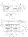
- FIG. 1 is a hydraulic circuit diagram of a working device control device for a construction machine of the prior art.
- first and second variable displacement hydraulic pumps 2 and 3 are connected to an engine 1 or the like.
- First and second hydraulic control levers 4 and 5 output control signals corresponding to the degree of manipulation.
- a first working device (not shown) is actuated by hydraulic fluid supplied through a supply passage 6 by the first hydraulic pump 2.
- a second working device (not shown) is actuated by hydraulic fluid supplied through a supply passage 8 by the second hydraulic pump 3.
- a first working device control valve 7 is disposed on the supply passage 6 between the first hydraulic pump 2 and the first working device.
- the first working device control valve 7 controls the direction and flow rate of hydraulic fluid supplied to the first working device.
- a second working device control valve 9 is disposed on the supply passage 8 between the second hydraulic pump 3 and the second working device.
- the second working device control valve 9 controls the direction and flow rate of hydraulic fluid supplied to the second working device.
- a confluence valve 10 is disposed on the supply passage 8, upstream of the second working device control valve 9.
- the confluence valve 10 is switched by pilot pressure applied by the first hydraulic control lever 4 so that the first and second working devices perform complex operations, the confluence valve 10 allows a portion of hydraulic fluid discharged from the second hydraulic pump 3 to flow through a confluence passage 14 to join hydraulic fluid discharged from the first hydraulic pump 2.
- a confluence shut-off valve 12 is disposed on a pilot line 11 through which pilot pressure is applied.
- the confluence shut-off valve 12 is switched by pilot pressure applied by the second hydraulic control lever 5, the confluence shut-off valve 12 shuts off the supply of pilot pressure to the confluence valve 10.
- MCV main control valve
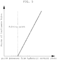
- the spool of the confluence valve 10 is not switched when pilot pressure from the first hydraulic control lever 4 is lower than the joining point and is switched when the pilot pressure becomes equal to or greater than the joining point.
- hydraulic fluid discharged from the second hydraulic pump 3 flows through the supply passage 8, an inner passage 10a of the switched confluence valve 10, and the confluence passage 14, and then in the passage 14a, joins hydraulic fluid that has been supplied by the first hydraulic pump 2 through the first working device control valve 7.
- the second working device control valve 9 When the spool of the second working device control valve 9 is switched by pilot pressure applied by the second hydraulic control lever 5 to operate the second working device, the second working device control valve 9 is supplied with an insufficient amount of hydraulic fluid from the second hydraulic pump 3, since a portion of hydraulic fluid discharged from the second hydraulic pump 3 has been supplied for the first working device in response to the switching of the confluence valve 10.
- pilot pressure is not formed in the pilot line 11 to a level desired by an operator, for various reasons, such as internal leakage or communication with a hydraulic fluid tank.
- a pilot line through which pilot pressure is applied by the first hydraulic control lever 4 to the first working device control valve 7, communicates with the pilot line 11. This causes pressure loss due to internal leakage or the like. Consequently, the operator cannot control the first working device as accurately as he or she may desire.
- the confluence shut-off valve 12 is configured such that the spool thereof can be mechanically controlled. Once the confluence shut-off valve 12 is assembled by setting the open area of the spool, it is difficult to adjust the open area. In addition, in construction machines, it is difficult to realize an approach of variably controlling the spool of the confluence valve 10 using pilot pressure by manipulating the first and second hydraulic control levers 4 and 5, which is problematic.
- control period of the right portion of the spool (to be used in joining for the first working device when the spool is switched) is different from the control period of the left portion of the spool (to be used in control over the other working device).
- valve springs on the right and left of the spool are required to have different specifications.
- FIG. 2 is a hydraulic circuit diagram of another working device control device for a construction machine of the prior art.
- first and second variable displacement hydraulic pumps 2 and 3 are connected to an engine 1 or the like.
- First and second hydraulic control levers 4 and 5 output control signals corresponding to the degree of manipulation.
- a first working device (not shown) is actuated by hydraulic fluid supplied through a supply passage 6 by the first hydraulic pump 2.
- a second working device (not shown) is actuated by hydraulic fluid supplied through a supply passage 8 by the second hydraulic pump 3.
- a first working device control valve 7 is disposed on the supply passage 6 between the first hydraulic pump 2 and the first working device.
- the first working device control valve 7 controls the direction and flow rate of hydraulic fluid supplied to the first working device.
- a second working device control valve 9 is disposed on the supply passage 8 between the second hydraulic pump 3 and the second working device.
- the second working device control valve 9 controls the direction and flow rate of hydraulic fluid supplied to the second working device.
- a confluence valve 10 is disposed on the supply passage 8, upstream of the second working device control valve 9.
- the confluence valve 10 is switched by pilot pressure applied by the first hydraulic control lever 4 so that the first and second working devices perform complex operations, the confluence valve 10 allows a portion of hydraulic fluid discharged from the second hydraulic pump 3 to flow through a confluence passage 14 to join hydraulic fluid discharged from the first hydraulic pump 2.
- a first pressure sensor 15 detects the level of pilot pressure applied to the second working device control valve 9 from the second hydraulic control lever 5.
- a first proportional control valve 16 is disposed on a pilot line 11 through which pilot pressure is applied to the confluence valve 10 by the first hydraulic control lever 4.
- the first proportional control valve 16 converts pilot pressure, formed in response to the first hydraulic control lever 4 being manipulated, to have a secondary pressure, proportional to an electrical signal applied to the first proportional control valve 16 and applies the secondary pressure to the confluence valve 10.
- a controller 17 has a detection signal input thereto by the first pressure sensor 15.
- the controller 17 applies an electrical signal to the first proportional control valve 16 so that a control signal, calculated to be inversely proportional to the input detection signal, can be applied to the confluence valve 10.
- the spool of the first working device control valve 7 is switched to the right, as depicted in the drawing, by pilot pressure applied thereto.
- pilot pressure formed in response to the first hydraulic control lever 4 being manipulated is converted to a secondary pilot pressure in response to an electrical signal applied to the first proportional control valve 16 by the controller 17.
- the level of secondary pressure is applied to the confluence valve 10 through the pilot line 11.
- pilot pressure applied to the second working device control valve 9 is detected by the first pressure sensor 15 and a detection signal is input to the controller 17.
- the controller 17 applies an electrical signal to the first proportional control valve 16 such that the electrical signal is inversely proportional to the level of pilot pressure applied to the second working device control valve 9.
- a secondary pilot pressure formed by the first proportional control valve 16 reduces pilot pressure which is otherwise applied to the confluence valve 10 by the first hydraulic control lever 4.
- the open area of the spool of the confluence valve 10 can be variably controlled depending on the level of pilot pressure applied by the second hydraulic control lever 5 to the second working device control valve 9.
- a pilot line through which pilot pressure is applied by the first hydraulic control lever 4 to the first working device control valve 7, communicates with the pilot line 11, through which pilot pressure is applied to the confluence valve 10 by the first hydraulic control lever 4.
- pilot pressure formed by manipulating the first hydraulic control lever 4 is used as pilot pressure supplied to the first proportional control valve 16
- a secondary pilot pressure formed by the first proportional control valve 16 cannot be arbitrarily changed.
- right and left valve springs of the spool of the confluence valve 10 are required to have different specifications.
- the present disclosure has been made in consideration of the above problems occurring in the related art, and the present disclosure provides a confluent flow control device for a working device of a construction machine, the device being able to precisely manipulate working devices when enabling the working devices to perform complex operations or allowing flows of fluid supplied to the working devices to join, thereby improving operability and convenience.
- a confluent flow control device for a working device of a construction machine, the device allowing pilot pressure to be supplied to a proportional control valve from a pilot pump to control pilot pressure supplied to a confluence valve, whereby the proportional control valve can output a secondary pilot pressure, different from a control signal output from a control lever.
- a confluent flow control device for a working device of a construction machine may include:
- the confluent flow control device may further include:
- a confluent flow control device for a working device of a construction machine may include:
- a method of controlling a confluent flow control device for a working device of a construction machine is provided.
- the device may include: first and second variable displacement hydraulic pumps; a pilot pump; first and second hydraulic control levers outputting control signals corresponding to degrees of manipulation; first and second working devices being actuated by hydraulic fluid supplied by the first and second hydraulic pumps; first and second working device control valves controlling operations of the first and second working devices when switched by pilot pressure applied thereto in response to the first and second hydraulic control levers being manipulated; a confluence valve, wherein the confluence valve, when switched by pilot pressure applied by the pilot pump, allows a portion of hydraulic fluid discharged from the second hydraulic pump to flow through a confluence passage to join hydraulic fluid discharged from the first hydraulic pump, whereby the first and second working devices perform complex operations; a first proportional control valve converting pilot pressure supplied to the confluence valve by the pilot pump to a secondary pressure corresponding to an electrical signal applied to the first proportional control valve; and a controller applying the electrical signal to the first proportional control valve, the electrical signal corresponding to pilot pressure formed in response to the first and second hydraulic control levers being
- the controlling method may include:
- the controlling method in a case of switching the second working device control valve by manipulating the second hydraulic control lever after a portion of hydraulic fluid discharged from the second hydraulic pump is allowed to join hydraulic fluid discharged from the first hydraulic pump through switching of the confluence valve in response to the first hydraulic control lever being manipulated, when a difference between levels of pilot pressure applied to the first and second working device control valves in response to the first and second hydraulic control levers being manipulated is greater than a specific level, joining of hydraulic fluid may be stopped by shutting off supply of pilot pressure to the confluence valve by applying an electrical signal to the first proportional control valve.
- a confluent flow control device for a working device of a construction machine.
- the device may include: first and second variable displacement hydraulic pumps; a pilot pump; first and second electrical control levers outputting control signals corresponding to degrees of manipulation; first and second working devices being actuated by hydraulic fluid supplied by the first and second hydraulic pumps; first and second working device control valves controlling operations of the first and second working devices when switched by electrical signals applied in response to the first and second electrical control levers being manipulated; a confluence valve, wherein the confluence valve, when switched by pilot pressure supplied by the pilot pump, allows a portion of hydraulic fluid discharged from the second hydraulic pump to flow through a confluence passage to join hydraulic fluid discharged from the first hydraulic pump, whereby the first and second working devices perform complex operations; a first proportional control valve converting pressure of hydraulic fluid supplied to the confluence valve by the pilot pump to a secondary pilot pressure corresponding to an applied electrical signal; a second proportional control valve converting pressure of hydraulic fluid supplied to the first working device control valve by the pilot pump to a secondary pilot pressure corresponding to an applied electrical signal; a third proportional
- the controlling method may include:
- the controlling method in a case of switching the second working device control valve by manipulating the second electrical control lever after a portion of hydraulic fluid discharged from the second hydraulic pump is allowed to join hydraulic fluid discharged from the first hydraulic pump through switching of the confluence valve in response to the first electrical control lever being manipulated, when a difference between levels of electrical signals applied to the second and third proportional control valves in response to the first and second electrical control levers being manipulated is greater than a specific level, the joining of hydraulic fluid may be stopped by shutting off supply of pilot pressure to the confluence valve by applying an electrical signal to the first proportional control valve.
- pilot pressure supplied to the proportional control valve to control pilot pressure supplied to the confluence valve is supplied by the pilot pump, the spools for the working devices can be switched without interruption, and the proportional control valve can output a secondary pilot pressure different from a control signal output from the control lever. Consequently, it is possible to precisely manipulate the working devices when allowing flows of fluid supplied to the working devices to join or enabling the working devices to perform complex operations.
- FIG. 3 is a hydraulic circuit diagram illustrating a first embodiment of a confluent flow control device for a working device of a construction machine according to the present disclosure
- FIG. 4 is a hydraulic circuit diagram illustrating a second embodiment of a confluent flow control device for a working device of a construction machine according to the present disclosure
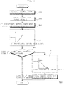
- FIG. 6 is a flowchart illustrating a method of controlling a confluent flow control device for a working device of a construction machine according to the first embodiment of the present disclosure
- FIG. 7 is a flowchart illustrating a confluence shutting-off method of the confluence valve in the method of controlling a confluent flow control device for a working device of a construction machine according to the first embodiment of the present disclosure
- FIG. 8 is a flowchart illustrating a method of controlling a confluent flow control device for a working device of a construction machine according to the present disclosure.
- the first embodiment of the confluent flow control device for a working device of a construction machine includes:
- FIG. 6 the first exemplary embodiment of the method of controlling a confluent flow control device for a working device of a construction machine is illustrated.
- the confluent flow control device includes: first and second variable displacement hydraulic pumps 2 and 3; a pilot pump 20; first and second hydraulic control levers 4 and 5 outputting control signals corresponding to the degree of manipulation; first and second working devices (not shown) being actuated by hydraulic fluid supplied by the first and second hydraulic pumps 2 and 3; first and second working device control valves 7 and 9 controlling the operations of the first and second working devices when switched by pilot pressure applied thereto in response to the first and second hydraulic control levers 4 and 5 being manipulated; a confluence valve 10, wherein the confluence valve 10, when switched by pilot pressure applied by the pilot pump 20, allows a portion of hydraulic fluid discharged from the second hydraulic pump 3 to flow through a confluence passage 14 to join hydraulic fluid discharged from the first hydraulic pump 2, whereby the first and second working devices perform complex operations; a first proportional control valve 16 converting pilot pressure supplied to the confluence valve 10 by the pilot pump 20 to a secondary pressure corresponding to an electrical signal applied thereto; and a controller 17 applying the electrical signal to the first
- the spool of the first working device control valve 7 is switched to the right, as depicted in the drawing, by pilot pressure applied thereto.
- hydraulic fluid discharged from the first hydraulic pump 2 is transferred to the passage 14a through the supply passage 6 and the first working device control valve 7.
- pilot pressure applied to the first working device control valve 7 is measured by the first pressure sensor 21 (S10, S100), and the measured pilot pressure is input to the controller 17.
- the pressure of hydraulic fluid supplied to the first proportional control valve 16 by the pilot pump 20 is converted to a secondary pilot pressure corresponding to an electrical signal applied by the controller 17 to the first proportional control valve 16.
- the converted secondary pilot pressure is applied to the confluence valve 10 to switch the spool thereof to the left, as depicted in the drawing.
- pilot pressure equal to, amplified from, or reduced from pilot pressure formed in response to the first hydraulic control lever 4 being manipulated may be used as a secondary pilot pressure applied to the confluence valve 10 by the first proportional control valve 16.
- the spool of the confluence valve 10 is switched to the left, as depicted in the drawing to correspond to pilot pressure applied by the first proportional control valve 16.
- hydraulic fluid discharged from the second hydraulic pump 3 is supplied to a first working device hydraulic cylinder (not shown) through the supply passage 8, the confluence valve 10, the supply passage 14, and the passage 14a.
- a level of pilot pressure applied to the second working device control valve 9 is measured by the second pressure sensor 15, and then the measured level of pilot pressure is input to the controller 17 (S200).
- the controller 17 compares the level of pilot pressure measured by the second pressure sensor 15 with a predetermined specific level (S40, S300).
- an electrical signal is applied to the first proportional control valve 16 to apply a level of pilot pressure to the confluence valve 10, the level of pilot pressure being obtained by multiplying a level of secondary pilot pressure output from the first proportional control valve 16 to be proportional to the degree of manipulation of the first hydraulic control lever 4 by a level of secondary pilot pressure output from the first proportional control valve 16 to be inversely proportional to the degree of manipulation of the second hydraulic control lever 5 (S50, S400).
- a joining percentage becomes zero "0" as represented by a graph "b" in FIG. 6 , whereby a secondary pilot pressure is not applied to the confluence valve 10 by the first proportional control valve 16.
- This causes the spool of the confluence valve 10 to return to the neutral position, thereby canceling a joining function. Consequently, hydraulic fluid discharged from the second hydraulic pump 3 can be supplied to a second working device hydraulic cylinder (not shown) through the supply passage 8, the confluence valve 10 in the neutral position, and the second working device control valve 9.
- the second embodiment of the confluent flow control device for a working device of a construction machine includes:
- FIG. 8 the second exemplary embodiment of the method of controlling a confluent flow control device for a working device of a construction machine is illustrated.
- the confluent flow control device includes: first and second variable displacement hydraulic pumps 2 and 3; a pilot pump 20; first and second electrical control levers 22 and 23 outputting control signals corresponding to the degree of manipulation; first and second working devices (not shown) being actuated by hydraulic fluid supplied by the first and second hydraulic pumps 2 and 3; first and second working device control valves 7 and 9 controlling the operations of the first and second working devices when switched by electrical signals in response to the first and second electrical control levers 22 and 23 being manipulated; a confluence valve 10, wherein the confluence valve 10, when switched by pilot pressure supplied by the pilot pump 20, allowing a portion of hydraulic fluid discharged from the second hydraulic pump 3 to flow through a confluence passage 14 to join hydraulic fluid discharged from the first hydraulic pump 2, whereby the first and second working devices perform complex operations; a first proportional control valve 16 converting the pressure of hydraulic fluid supplied to the confluence valve 10 by the pilot pump 20 to a secondary pilot pressure corresponding to an applied electrical signal; a second proportional control valve 19 converting the pressure
- the other components are the same as those of the confluent flow control device for a working device illustrated in FIG. 3 . Descriptions of the same components will be omitted, and the same reference numerals or signs will be used to designate the same or like components.
- an electrical signal corresponding to the degree of manipulation of the first electrical control lever 22 is input to the controller 17.
- the second proportional control valve 19 converts the pressure of hydraulic fluid supplied by the pilot pump 20 to a secondary pilot pressure, based on an electrical signal applied by the controller 17 corresponding to the degree of manipulation of the first electrical control lever 22, and applies the converted secondary pilot pressure to the first working device control valve 7.
- the controller 17 applies an electrical signal corresponding to the degree of manipulation of the first electrical control lever 22 to the first proportional control valve 16. Subsequently, the first proportional control valve 16 converts the pressure of hydraulic fluid supplied by the pilot pump 20 to a secondary pilot pressure corresponding to the electrical signal, and the converted secondary pilot pressure is applied to the confluence valve 10 to switch the spool to the left, as depicted in the drawing.
- hydraulic fluid discharged from the second hydraulic pump 3 is transferred to the passage 14a through the supply passage 8, confluence valve 10, and the confluence passage to join hydraulic fluid supplied to the passage 14a by the first hydraulic pump 2, and then a confluent flow of hydraulic fluid is supplied to a hydraulic cylinder for the first working device.
- an electrical signal corresponding to the degree of manipulation of the second electrical control lever 23 is input to the controller 17.
- the third proportional control valve 18 converts the pressure of hydraulic fluid supplied by the pilot pump 20 to secondary pilot pressure, based on an electrical signal applied by the controller 17 corresponding to the degree of manipulation of the second electrical control lever 23, and applies the converted secondary pilot pressure to the second working device control valve 9.
- an electrical signal is applied to the first proportional control valve 16 to apply a level of pilot pressure to the confluence valve 10, the level of pilot pressure being obtained by multiplying a level of secondary pilot pressure output from the first proportional control valve 16 to be proportional to the degree of manipulation of the first electrical control lever 22 by a level of secondary pilot pressure output from the first proportional control valve 16 to be inversely proportional to the degree of manipulation of the second electrical control lever 23.
- the operability of accurately and reliably manipulating the confluence valve is obtained, thereby providing convenience to an operator.
- pilot pressure supplied to the proportional control valve to control pilot pressure supplied to the confluence valve is supplied by the pilot pump, the spools for the working devices can be switched without interruption, and it is possible that the proportional control valve outputs secondary pilot pressure different from a control signal output from the control lever.
Landscapes
- Engineering & Computer Science (AREA)
- General Engineering & Computer Science (AREA)
- Mining & Mineral Resources (AREA)
- Civil Engineering (AREA)
- Structural Engineering (AREA)
- Physics & Mathematics (AREA)
- Fluid Mechanics (AREA)
- Mechanical Engineering (AREA)
- Fluid-Pressure Circuits (AREA)
- Operation Control Of Excavators (AREA)
Abstract
Description
- The present disclosure relates to a confluent flow control device for a working device of a construction machine and a method of controlling the same. More particularly, the present disclosure relates to a confluent flow control device for a working device of a construction machine, the device being able to precisely manipulate working devices when allowing flows of fluid supplied to the working devices to join or controlling the working devices to perform complex operations, and a method of controlling the same.
-
FIG. 1 is a hydraulic circuit diagram of a working device control device for a construction machine of the prior art. - As illustrated in
FIG. 1 , first and second variable displacement hydraulic pumps (hereinafter referred to as first and second hydraulic pumps) 2 and 3 are connected to anengine 1 or the like. - First and second hydraulic control levers 4 and 5 output control signals corresponding to the degree of manipulation.
- A first working device (not shown) is actuated by hydraulic fluid supplied through a
supply passage 6 by the firsthydraulic pump 2. - A second working device (not shown) is actuated by hydraulic fluid supplied through a
supply passage 8 by the secondhydraulic pump 3. - A first working
device control valve 7 is disposed on thesupply passage 6 between the firsthydraulic pump 2 and the first working device. When the first workingdevice control valve 7 is switched by pilot pressure applied by the firsthydraulic control lever 4, the first workingdevice control valve 7 controls the direction and flow rate of hydraulic fluid supplied to the first working device. - A second working
device control valve 9 is disposed on thesupply passage 8 between the secondhydraulic pump 3 and the second working device. When the second workingdevice control valve 9 is switched by pilot pressure applied by the secondhydraulic control lever 5, the second workingdevice control valve 9 controls the direction and flow rate of hydraulic fluid supplied to the second working device. - A
confluence valve 10 is disposed on thesupply passage 8, upstream of the second workingdevice control valve 9. When theconfluence valve 10 is switched by pilot pressure applied by the firsthydraulic control lever 4 so that the first and second working devices perform complex operations, theconfluence valve 10 allows a portion of hydraulic fluid discharged from the secondhydraulic pump 3 to flow through aconfluence passage 14 to join hydraulic fluid discharged from the firsthydraulic pump 2. - A confluence shut-off
valve 12 is disposed on apilot line 11 through which pilot pressure is applied. When the confluence shut-offvalve 12 is switched by pilot pressure applied by the secondhydraulic control lever 5, the confluence shut-offvalve 12 shuts off the supply of pilot pressure to theconfluence valve 10. -
Reference numeral 13 in the drawings, while not referred to, is a main control valve (MCV). - When the first
hydraulic control lever 4 is manipulated to operate the first working device, a spool is switched to the right, as depicted in the drawing, by pilot pressure applied to the first workingdevice control valve 7. Subsequently, hydraulic fluid supplied by the firsthydraulic pump 2 is supplied to a hydraulic cylinder for the first working device through thesupply passage 6, the switched first workingdevice control valve 7, and apassage 14a. - When the flow rate of hydraulic fluid required by the first working device is greater than the maximum flow rate of hydraulic fluid supplied by the first
hydraulic pump 2, a portion of hydraulic fluid discharged from the secondhydraulic pump 3 is allowed to join hydraulic fluid discharged from the firsthydraulic pump 2. That is, in response to the firsthydraulic control lever 4 being manipulated, pilot pressure is applied to the first workingdevice control valve 7. At the same time, in response to the firsthydraulic control lever 4 being manipulated, pilot pressure is applied to theconfluence valve 10 through thepilot line 11 and then through the confluence shut-offvalve 12. Here, the spool of theconfluence valve 10 is switched to the left, as depicted in the drawing. - As illustrated in
FIG. 5 , the spool of theconfluence valve 10 is not switched when pilot pressure from the firsthydraulic control lever 4 is lower than the joining point and is switched when the pilot pressure becomes equal to or greater than the joining point. Thus, hydraulic fluid discharged from the secondhydraulic pump 3 flows through thesupply passage 8, aninner passage 10a of the switchedconfluence valve 10, and theconfluence passage 14, and then in thepassage 14a, joins hydraulic fluid that has been supplied by the firsthydraulic pump 2 through the first workingdevice control valve 7. - When the spool of the second working
device control valve 9 is switched by pilot pressure applied by the secondhydraulic control lever 5 to operate the second working device, the second workingdevice control valve 9 is supplied with an insufficient amount of hydraulic fluid from the secondhydraulic pump 3, since a portion of hydraulic fluid discharged from the secondhydraulic pump 3 has been supplied for the first working device in response to the switching of theconfluence valve 10. - When the second
hydraulic control lever 5 is manipulated to prevent this problem, pilot pressure is applied to the second workingdevice control valve 9 and the confluence shut-offvalve 12. Here, the spool of the confluence shut-offvalve 12 is switched downwardly, as depicted in the drawing. - Thus, it is possible to ensure that hydraulic fluid is supplied to the second working device by the second
hydraulic pump 3 by shutting off pilot pressure applied to theconfluence valve 10 by the firsthydraulic control lever 4 to be proportional to pilot pressure applied by the secondhydraulic control lever 5. - Here, according to the characteristics of the spool of the confluence shut-off
valve 12, in a transition period before the spool is switched to a full open state, pilot pressure is not formed in thepilot line 11 to a level desired by an operator, for various reasons, such as internal leakage or communication with a hydraulic fluid tank. - In addition, a pilot line, through which pilot pressure is applied by the first
hydraulic control lever 4 to the first workingdevice control valve 7, communicates with thepilot line 11. This causes pressure loss due to internal leakage or the like. Consequently, the operator cannot control the first working device as accurately as he or she may desire. - In addition, the confluence shut-off
valve 12 is configured such that the spool thereof can be mechanically controlled. Once the confluence shut-offvalve 12 is assembled by setting the open area of the spool, it is difficult to adjust the open area. In addition, in construction machines, it is difficult to realize an approach of variably controlling the spool of theconfluence valve 10 using pilot pressure by manipulating the first and second hydraulic control levers 4 and 5, which is problematic. - In addition, in the
confluence valve 10, the control period of the right portion of the spool (to be used in joining for the first working device when the spool is switched) is different from the control period of the left portion of the spool (to be used in control over the other working device). Thus, valve springs on the right and left of the spool are required to have different specifications. -
FIG. 2 is a hydraulic circuit diagram of another working device control device for a construction machine of the prior art. - As illustrated in
FIG. 2 , first and second variable displacement hydraulic pumps (hereinafter referred to as first and second hydraulic pumps) 2 and 3 are connected to anengine 1 or the like. - First and second hydraulic control levers 4 and 5 output control signals corresponding to the degree of manipulation.
- A first working device (not shown) is actuated by hydraulic fluid supplied through a
supply passage 6 by the firsthydraulic pump 2. - A second working device (not shown) is actuated by hydraulic fluid supplied through a
supply passage 8 by the secondhydraulic pump 3. - A first working
device control valve 7 is disposed on thesupply passage 6 between the firsthydraulic pump 2 and the first working device. When the first workingdevice control valve 7 is switched by pilot pressure applied by the firsthydraulic control lever 4, the first workingdevice control valve 7 controls the direction and flow rate of hydraulic fluid supplied to the first working device. - A second working
device control valve 9 is disposed on thesupply passage 8 between the secondhydraulic pump 3 and the second working device. When the second workingdevice control valve 9 is switched by pilot pressure applied by the secondhydraulic control lever 5, the second workingdevice control valve 9 controls the direction and flow rate of hydraulic fluid supplied to the second working device. - A
confluence valve 10 is disposed on thesupply passage 8, upstream of the second workingdevice control valve 9. When theconfluence valve 10 is switched by pilot pressure applied by the firsthydraulic control lever 4 so that the first and second working devices perform complex operations, theconfluence valve 10 allows a portion of hydraulic fluid discharged from the secondhydraulic pump 3 to flow through aconfluence passage 14 to join hydraulic fluid discharged from the firsthydraulic pump 2. - A
first pressure sensor 15 detects the level of pilot pressure applied to the second workingdevice control valve 9 from the secondhydraulic control lever 5. - A first
proportional control valve 16 is disposed on apilot line 11 through which pilot pressure is applied to theconfluence valve 10 by the firsthydraulic control lever 4. The firstproportional control valve 16 converts pilot pressure, formed in response to the firsthydraulic control lever 4 being manipulated, to have a secondary pressure, proportional to an electrical signal applied to the firstproportional control valve 16 and applies the secondary pressure to theconfluence valve 10. - A
controller 17 has a detection signal input thereto by thefirst pressure sensor 15. Thecontroller 17 applies an electrical signal to the firstproportional control valve 16 so that a control signal, calculated to be inversely proportional to the input detection signal, can be applied to theconfluence valve 10. - Thus, when the first
hydraulic control lever 4 is manipulated to operate the first working device, the spool of the first workingdevice control valve 7 is switched to the right, as depicted in the drawing, by pilot pressure applied thereto. At the same time, pilot pressure formed in response to the firsthydraulic control lever 4 being manipulated is converted to a secondary pilot pressure in response to an electrical signal applied to the firstproportional control valve 16 by thecontroller 17. The level of secondary pressure is applied to theconfluence valve 10 through thepilot line 11. - Here, when the spool of the second working
device control valve 9 is switched in response to the secondhydraulic control lever 5 being manipulated to operate the second working device, pilot pressure applied to the second workingdevice control valve 9 is detected by thefirst pressure sensor 15 and a detection signal is input to thecontroller 17. - At this time, the
controller 17 applies an electrical signal to the firstproportional control valve 16 such that the electrical signal is inversely proportional to the level of pilot pressure applied to the second workingdevice control valve 9. Thus, a secondary pilot pressure formed by the firstproportional control valve 16 reduces pilot pressure which is otherwise applied to theconfluence valve 10 by the firsthydraulic control lever 4. - Consequently, the open area of the spool of the
confluence valve 10 can be variably controlled depending on the level of pilot pressure applied by the secondhydraulic control lever 5 to the second workingdevice control valve 9. - In addition, a pilot line, through which pilot pressure is applied by the first
hydraulic control lever 4 to the first workingdevice control valve 7, communicates with thepilot line 11, through which pilot pressure is applied to theconfluence valve 10 by the firsthydraulic control lever 4. This causes pressure loss due to internal leakage or the like. Consequently, the operator cannot control the first working device as accurately as he or she desires. - In addition, in the case of switching the spool of the first working
device control valve 7 by manipulating the firsthydraulic control lever 4, a portion of pilot pressure for switching the first workingdevice control valve 7 influences the spool of theconfluence valve 10 through thepilot line 11. In such a case, it is impossible to precisely manipulate the first and second working devices, which is problematic. - Furthermore, since pilot pressure formed by manipulating the first
hydraulic control lever 4 is used as pilot pressure supplied to the firstproportional control valve 16, a secondary pilot pressure formed by the firstproportional control valve 16 cannot be arbitrarily changed. Thus, right and left valve springs of the spool of theconfluence valve 10 are required to have different specifications. - Accordingly, the present disclosure has been made in consideration of the above problems occurring in the related art, and the present disclosure provides a confluent flow control device for a working device of a construction machine, the device being able to precisely manipulate working devices when enabling the working devices to perform complex operations or allowing flows of fluid supplied to the working devices to join, thereby improving operability and convenience.
- Also provided is a confluent flow control device for a working device of a construction machine, the device allowing pilot pressure to be supplied to a proportional control valve from a pilot pump to control pilot pressure supplied to a confluence valve, whereby the proportional control valve can output a secondary pilot pressure, different from a control signal output from a control lever.
- According to an aspect of the present disclosure, a confluent flow control device for a working device of a construction machine may include:
- a first variable displacement hydraulic pump, a second variable displacement hydraulic pump, and a pilot pump;
- a first hydraulic control lever and a second hydraulic control lever outputting control signals corresponding to degrees of manipulation;
- a first working device being actuated by hydraulic fluid supplied by the first hydraulic pump;
- a second working device being actuated by hydraulic fluid supplied by the second hydraulic pump;
- a first working device control valve disposed on a supply passage between the first hydraulic pump and the first working device to control a direction and flow rate of hydraulic fluid supplied to the first working device when switched by pilot pressure applied thereto in response to the first hydraulic control lever being manipulated;
- a second working device control valve disposed on a supply passage between the second hydraulic pump and the second working device to control a direction and flow rate of hydraulic fluid supplied to the second working device when switched by pilot pressure applied thereto in response to the second hydraulic control lever being manipulated;
- a confluence valve disposed on the supply passage between the second hydraulic pump and the second working device, upstream of the second working device control valve, wherein the confluence valve, when switched by pilot pressure supplied by the pilot pump, allows a portion of hydraulic fluid discharged from the second hydraulic pump to flow through a confluence passage to join hydraulic fluid discharged from the first hydraulic pump, whereby the first and second working devices perform complex operations;
- a first proportional control valve disposed on a pilot line between the pilot pump and the confluence valve to convert pilot pressure supplied to the confluence valve by the pilot pump to secondary pressure corresponding to an electrical signal applied to first proportional control valve and applying the converted secondary pressure to the confluence valve; and
- a controller calculating the electrical signal from pilot pressure applied to the first working device control valve and the second working device control valve to be proportional to degrees of manipulation of the first hydraulic control lever and the second hydraulic control lever and applying the calculated electrical signals to the first proportional control valve.
- The confluent flow control device may further include:
- a first pressure sensor detecting a level of pilot pressure applied to the first working device control valve to be proportional to the degree of manipulation of the first hydraulic control lever and inputting the detected level of pilot pressure to the controller; and
- a second pressure sensor detecting a level of pilot pressure applied to the second working device control valve to be proportional to the degree of manipulation of the second hydraulic control lever and inputting the detected level of pilot pressure to the controller.
- According to another aspect of the present disclosure, a confluent flow control device for a working device of a construction machine may include:
- a first variable displacement hydraulic pump, a second variable displacement hydraulic pump, and a pilot pump;
- a first electrical control lever and a second electrical control lever outputting control signals corresponding to degrees of manipulation;
- a first working device being actuated by hydraulic fluid supplied by the first hydraulic pump;
- a second working device being actuated by hydraulic fluid supplied by the second hydraulic pump;
- a first working device control valve disposed on a supply passage between the first hydraulic pump and the first working device to control a direction and flow rate of hydraulic fluid supplied to the first working device when switched by pilot pressure applied by the pilot pump, with the pilot pressure corresponding to a degree of manipulation of the first electrical control lever;
- a second working device control valve disposed on a supply passage between the second hydraulic pump and the second working device to control a direction and flow rate of hydraulic fluid supplied to the second working device when switched by pilot pressure applied by the pilot pump, with the pilot pressure corresponding to a degree of manipulation of the second electrical control lever;
- a confluence valve disposed on the supply passage between the second hydraulic pump and the second working device, upstream of the second working device control valve, wherein the confluence valve, when switched by pilot pressure supplied by the pilot pump, allows a portion of hydraulic fluid discharged from the second hydraulic pump to flow through a confluence passage to join hydraulic fluid discharged from the first hydraulic pump, whereby the first and second working devices perform complex operations;
- a first proportional control valve disposed on a pilot line between the pilot pump and the confluence valve to convert pressure of hydraulic fluid supplied by the pilot pump to a secondary pilot pressure corresponding to an electrical signal applied to the first proportional control valve and apply the converted secondary pilot pressure to the confluence valve;
- a second proportional control valve disposed on a pilot line between the pilot pump and the first working device control valve to convert pressure of hydraulic fluid supplied by the pilot pump to a secondary pilot pressure corresponding to an electrical signal applied to the second proportional control valve corresponding to the degree of manipulation of the first electrical control lever, and apply the converted secondary pilot pressure to the first working device control valve;
- a third proportional control valve disposed on a pilot line between the pilot pump and the second working device control valve to convert pressure of hydraulic fluid supplied by the pilot pump to a secondary pilot pressure corresponding to an electrical signal applied to the third proportional control valve corresponding to the degree of manipulation of the second electrical control lever, and apply the converted secondary pilot pressure to the second working device control valve; and
- a controller calculating the electrical signal from the electrical signals applied to the second proportional control valve and the third proportional control valve to be proportional to the degrees of manipulation of the first electrical control lever and the second electrical control lever and applying the calculated electrical signals to the first proportional control valve.
- According to another aspect of the present disclosure, provided is a method of controlling a confluent flow control device for a working device of a construction machine.
- In the controlling method, the device may include: first and second variable displacement hydraulic pumps; a pilot pump; first and second hydraulic control levers outputting control signals corresponding to degrees of manipulation; first and second working devices being actuated by hydraulic fluid supplied by the first and second hydraulic pumps; first and second working device control valves controlling operations of the first and second working devices when switched by pilot pressure applied thereto in response to the first and second hydraulic control levers being manipulated; a confluence valve, wherein the confluence valve, when switched by pilot pressure applied by the pilot pump, allows a portion of hydraulic fluid discharged from the second hydraulic pump to flow through a confluence passage to join hydraulic fluid discharged from the first hydraulic pump, whereby the first and second working devices perform complex operations; a first proportional control valve converting pilot pressure supplied to the confluence valve by the pilot pump to a secondary pressure corresponding to an electrical signal applied to the first proportional control valve; and a controller applying the electrical signal to the first proportional control valve, the electrical signal corresponding to pilot pressure formed in response to the first and second hydraulic control levers being manipulated.
- The controlling method may include:
- detecting a level of pilot pressure formed in response to the first hydraulic control lever being manipulated and detecting a level of pilot pressure formed in response to the second hydraulic control lever being manipulated;
- converting pilot pressure supplied to the first proportional control valve by the pilot pump to a secondary pilot pressure based on an electrical signal applied to the first proportional control valve to be proportional to a degree of manipulation of the first hydraulic control lever and applying the secondary pilot pressure to the confluence valve;
- comparing the level of pilot pressure detected in response to the second hydraulic control lever being manipulated with a predetermined specific level; and
- when the level of pilot pressure detected in response to the second hydraulic control lever being manipulated is greater than the specific level, applying an electrical signal to the first proportional control valve to apply a level of pilot pressure to the confluence valve, the level of pilot pressure being obtained by multiplying a level of secondary pilot pressure output from the first proportional control valve to be proportional to the degree of manipulation of the first hydraulic control lever by a level of secondary pilot pressure output from the first proportional control valve to be inversely proportional to a degree of manipulation of the second hydraulic control lever.
- In the controlling method, in a case of switching the second working device control valve by manipulating the second hydraulic control lever after a portion of hydraulic fluid discharged from the second hydraulic pump is allowed to join hydraulic fluid discharged from the first hydraulic pump through switching of the confluence valve in response to the first hydraulic control lever being manipulated, when a difference between levels of pilot pressure applied to the first and second working device control valves in response to the first and second hydraulic control levers being manipulated is greater than a specific level, joining of hydraulic fluid may be stopped by shutting off supply of pilot pressure to the confluence valve by applying an electrical signal to the first proportional control valve.
- According to another aspect of the present disclosure, provided is method of controlling a confluent flow control device for a working device of a construction machine.
- In the controlling method, the device may include: first and second variable displacement hydraulic pumps; a pilot pump; first and second electrical control levers outputting control signals corresponding to degrees of manipulation; first and second working devices being actuated by hydraulic fluid supplied by the first and second hydraulic pumps; first and second working device control valves controlling operations of the first and second working devices when switched by electrical signals applied in response to the first and second electrical control levers being manipulated; a confluence valve, wherein the confluence valve, when switched by pilot pressure supplied by the pilot pump, allows a portion of hydraulic fluid discharged from the second hydraulic pump to flow through a confluence passage to join hydraulic fluid discharged from the first hydraulic pump, whereby the first and second working devices perform complex operations; a first proportional control valve converting pressure of hydraulic fluid supplied to the confluence valve by the pilot pump to a secondary pilot pressure corresponding to an applied electrical signal; a second proportional control valve converting pressure of hydraulic fluid supplied to the first working device control valve by the pilot pump to a secondary pilot pressure corresponding to an applied electrical signal; a third proportional control valve converting the pressure of hydraulic fluid supplied to the second working device control valve by the pilot pump to a secondary pilot pressure corresponding to an applied electrical signal; and a controller calculating the electrical signal from the electrical signals applied to the second and third proportional control valves to be proportional to degrees of manipulation of the first and second electrical control levers and applying the calculated electrical signal to the first proportional control valve.
- The controlling method may include:
- detecting an electrical signal generated in response to the first electrical control lever being manipulated;
- calculating an electrical signal to be proportional to the degree of manipulation of the first electrical control lever and applying the calculated electrical signal to the second proportional control valve;
- detecting an electrical signal generated in response to the second electrical control lever being manipulated;
- calculating an electrical signal to be proportional to the degree of manipulation of the second electrical control lever and applying the calculated electrical signal to the third proportional control valve;
- converting pilot pressure supplied to the first proportional control valve by the pilot pump to a secondary pilot pressure based on an electrical signal applied to the first proportional control valve to be proportional to the degree of manipulation of the first electrical control lever and applying the converted secondary pilot pressure to the confluence valve;
- comparing a level of an electrical signal detected in response to the second electrical control lever being manipulated with a predetermined specific level; and
- when the level of the electrical signal detected in response to the second electrical control lever being manipulated is greater than the specific level, applying an electrical signal to the first proportional control valve to apply a level of pilot pressure to the confluence valve, the level of pilot pressure being obtained by multiplying a level of secondary pilot pressure output from the first proportional control valve to be proportional to the degree of manipulation of the first electrical control lever by a level of secondary pilot pressure output from the first proportional control valve to be inversely proportional to the degree of manipulation of the second electrical control lever.
- In the controlling method, in a case of switching the second working device control valve by manipulating the second electrical control lever after a portion of hydraulic fluid discharged from the second hydraulic pump is allowed to join hydraulic fluid discharged from the first hydraulic pump through switching of the confluence valve in response to the first electrical control lever being manipulated, when a difference between levels of electrical signals applied to the second and third proportional control valves in response to the first and second electrical control levers being manipulated is greater than a specific level, the joining of hydraulic fluid may be stopped by shutting off supply of pilot pressure to the confluence valve by applying an electrical signal to the first proportional control valve.
- According to the present disclosure as set forth above, when flows of fluid supplied to working devices to enable the working devices to perform complex operations join, the operability of accurately and reliably manipulating the confluence valve is obtained, thereby providing convenience to an operator.
- In addition, since pilot pressure supplied to the proportional control valve to control pilot pressure supplied to the confluence valve is supplied by the pilot pump, the spools for the working devices can be switched without interruption, and the proportional control valve can output a secondary pilot pressure different from a control signal output from the control lever. Consequently, it is possible to precisely manipulate the working devices when allowing flows of fluid supplied to the working devices to join or enabling the working devices to perform complex operations.
-
-
FIG. 1 is a hydraulic circuit diagram illustrating a working device control device for a construction machine of the prior art; -
FIG. 2 is a hydraulic circuit diagram illustrating another working device control device for a construction machine of the prior art; -
FIG. 3 is a hydraulic circuit diagram illustrating a first embodiment of a confluent flow control device for a working device of a construction machine according to the present disclosure; -
FIG. 4 is a hydraulic circuit diagram illustrating a second embodiment of a confluent flow control device for a working device of a construction machine according to the present disclosure; -
FIG. 5 is a graph illustrating the characteristics of a valve spring of a working device confluence spool illustrated inFIG. 1 ; -
FIG. 6 is a flowchart illustrating a method of controlling a confluent flow control device for a working device of a construction machine according to the first embodiment of the present disclosure; -
FIG. 7 is a flowchart illustrating a confluence shutting-off method of the confluence valve in the method of controlling a confluent flow control device for a working device of a construction machine according to the first embodiment of the present disclosure; and -
FIG. 8 is a flowchart illustrating the method of controlling a confluent flow control device for a working device of a construction machine according to the second embodiment of the present disclosure. -
- 1: engine
- 2: first hydraulic pump
- 3: second hydraulic pump
- 4: first hydraulic control lever
- 5: second hydraulic control lever
- 6, 8: supply passage
- 7: first working device control valve
- 9: second working device control valve
- 10: confluence valve
- Hereinafter, a confluent flow control device for a working device of a construction machine and a method of controlling the same according to exemplary embodiments of the present disclosure will be described in detail with reference to the accompanying drawings.
-
FIG. 3 is a hydraulic circuit diagram illustrating a first embodiment of a confluent flow control device for a working device of a construction machine according to the present disclosure,FIG. 4 is a hydraulic circuit diagram illustrating a second embodiment of a confluent flow control device for a working device of a construction machine according to the present disclosure,FIG. 6 is a flowchart illustrating a method of controlling a confluent flow control device for a working device of a construction machine according to the first embodiment of the present disclosure,FIG. 7 is a flowchart illustrating a confluence shutting-off method of the confluence valve in the method of controlling a confluent flow control device for a working device of a construction machine according to the first embodiment of the present disclosure, andFIG. 8 is a flowchart illustrating a method of controlling a confluent flow control device for a working device of a construction machine according to the present disclosure. - Referring to
FIG. 3 , the first embodiment of the confluent flow control device for a working device of a construction machine according to the present disclosure includes: - a first variable displacement
hydraulic pump 2, a second variable displacementhydraulic pump 3, and apilot pump 20; - a first
hydraulic control lever 4 and a secondhydraulic control lever 5 outputting control signals corresponding to the degree of manipulation; - a first working device (not shown) being actuated by hydraulic fluid supplied by the first
hydraulic pump 2; - a second working device (not shown) being actuated by hydraulic fluid supplied by the second hydraulic pump;
- a first working
device control valve 7 disposed on asupply passage 6 between the firsthydraulic pump 2 and the first working device to control the direction and flow rate of hydraulic fluid supplied to the first working device when switched by pilot pressure applied thereto in response to the firsthydraulic control lever 4 being manipulated; - a second working
device control valve 9 disposed on asupply passage 8 between the secondhydraulic pump 3 and the second working device to control the direction and flow rate of hydraulic fluid supplied to the second working device when switched by pilot pressure applied thereto in response to the secondhydraulic control lever 5 being manipulated; - a
confluence valve 10 disposed on thesupply passage 8, upstream of the second workingdevice control valve 9, wherein theconfluence valve 10, when switched by pilot pressure supplied by thepilot pump 20, allows a portion of hydraulic fluid discharged from the secondhydraulic pump 3 to flow through aconfluence passage 14 to join hydraulic fluid discharged from the firsthydraulic pump 2, whereby the first and second working devices perform complex operations; - a first
proportional control valve 16 disposed on apilot line 11 between thepilot pump 20 and theconfluence valve 10 to convert pilot pressure supplied to theconfluence valve 10 by thepilot pump 20 to a secondary pressure corresponding to an electrical signal applied thereto and applying the secondary pressure to theconfluence valve 10; - a
controller 17 calculating the electrical signal from pilot pressures applied to the first workingdevice control valve 7 and the second workingdevice control valve 9 to be proportional to the degree of manipulation of the firsthydraulic control lever 4 and the secondhydraulic control lever 5 and applying the electrical signal to the firstproportional control valve 16; - a
first pressure sensor 21 detecting a level of pilot pressure applied to the first workingdevice control valve 7 to be proportional to the degree of manipulation of the firsthydraulic control lever 4 and inputting the detected level of pilot pressure to thecontroller 17; and - a
second pressure sensor 15 detecting a level of pilot pressure applied to the second workingdevice control valve 9 to be proportional to the degree of manipulation of the secondhydraulic control lever 5 and inputting the detected level of pilot pressure to thecontroller 17. - Referring to
FIG. 6 , the first exemplary embodiment of the method of controlling a confluent flow control device for a working device of a construction machine is illustrated. - In the controlling method, the confluent flow control device includes: first and second variable displacement hydraulic pumps 2 and 3; a pilot pump 20; first and second hydraulic control levers 4 and 5 outputting control signals corresponding to the degree of manipulation; first and second working devices (not shown) being actuated by hydraulic fluid supplied by the first and second hydraulic pumps 2 and 3; first and second working device control valves 7 and 9 controlling the operations of the first and second working devices when switched by pilot pressure applied thereto in response to the first and second hydraulic control levers 4 and 5 being manipulated; a confluence valve 10, wherein the confluence valve 10, when switched by pilot pressure applied by the pilot pump 20, allows a portion of hydraulic fluid discharged from the second hydraulic pump 3 to flow through a confluence passage 14 to join hydraulic fluid discharged from the first hydraulic pump 2, whereby the first and second working devices perform complex operations; a first proportional control valve 16 converting pilot pressure supplied to the confluence valve 10 by the pilot pump 20 to a secondary pressure corresponding to an electrical signal applied thereto; and a controller 17 applying the electrical signal to the first proportional control valve 16, the electrical signal corresponding to pilot pressures formed in response to the first and second hydraulic control levers 4 and 5 being manipulated. The controlling method includes:
- Step S10 of detecting a level of pilot pressure formed in response to the first
hydraulic control lever 4 being manipulated and step S20 of detecting a level of pilot pressure formed in response to the secondhydraulic control lever 5 being manipulated; - Step S30 of forming pilot pressure supplied to the first
proportional control valve 16 by thepilot pump 20 to a secondary pilot pressure based on an electrical signal applied to the firstproportional control valve 16 to be proportional to the degree of manipulation of the firsthydraulic control lever 4 and applying the formed secondary pilot pressure to theconfluence valve 10; - Step S40 of comparing the level of pilot pressure detected in response to the second
hydraulic control lever 5 being manipulated with a predetermined specific level; and - Step S50 of applying, when the level of pilot pressure detected in response to the second
hydraulic control lever 5 being manipulated is greater than the specific level, an electrical signal to the firstproportional control valve 16 to apply a level of pilot pressure to theconfluence valve 10, the level of pilot pressure being obtained by multiplying a level of secondary pilot pressure output from the firstproportional control valve 16 to be proportional to the degree of manipulation of the firsthydraulic control lever 4 by a level of secondary pilot pressure output from the firstproportional control valve 16 to be inversely proportional to the degree of manipulation of the secondhydraulic control lever 5. - In the case in which the second working
device control valve 9 is switched by manipulating the secondhydraulic control lever 5 after a portion of hydraulic fluid discharged from the secondhydraulic pump 3 is allowed to join hydraulic fluid discharged from the firsthydraulic pump 2 through switching of theconfluence valve 10 in response to the firsthydraulic control lever 4 being manipulated, when a difference between the levels of pilot pressure applied to the first and second workingdevice control valves hydraulic control levers confluence valve 10 by applying an electrical signal to the firstproportional control valve 16. - According to the above described configuration, when the first
hydraulic control lever 4 is manipulated to operate the first working device, the spool of the first workingdevice control valve 7 is switched to the right, as depicted in the drawing, by pilot pressure applied thereto. In response to the switching of the first workingdevice control valve 7, hydraulic fluid discharged from the firsthydraulic pump 2 is transferred to thepassage 14a through thesupply passage 6 and the first workingdevice control valve 7. - Here, when the degree of manipulation of the first
hydraulic control lever 4 is increased, pilot pressure applied to the first workingdevice control valve 7 is measured by the first pressure sensor 21 (S10, S100), and the measured pilot pressure is input to thecontroller 17. - Thus, the pressure of hydraulic fluid supplied to the first
proportional control valve 16 by thepilot pump 20 is converted to a secondary pilot pressure corresponding to an electrical signal applied by thecontroller 17 to the firstproportional control valve 16. The converted secondary pilot pressure is applied to theconfluence valve 10 to switch the spool thereof to the left, as depicted in the drawing. - Here, since the pressure of hydraulic fluid supplied to the first
proportional control valve 16 by thepilot pump 20 is used as a first pressure, pilot pressure equal to, amplified from, or reduced from pilot pressure formed in response to the firsthydraulic control lever 4 being manipulated may be used as a secondary pilot pressure applied to theconfluence valve 10 by the firstproportional control valve 16. - Subsequently, the spool of the
confluence valve 10 is switched to the left, as depicted in the drawing to correspond to pilot pressure applied by the firstproportional control valve 16. Thus, hydraulic fluid discharged from the secondhydraulic pump 3 is supplied to a first working device hydraulic cylinder (not shown) through thesupply passage 8, theconfluence valve 10, thesupply passage 14, and thepassage 14a. - Here, when the second
hydraulic control lever 5 is manipulated to operate the second working device, a level of pilot pressure applied to the second workingdevice control valve 9 is measured by thesecond pressure sensor 15, and then the measured level of pilot pressure is input to the controller 17 (S200). - The
controller 17 compares the level of pilot pressure measured by thesecond pressure sensor 15 with a predetermined specific level (S40, S300). - When the level of pilot pressure input in response to the second
hydraulic control lever 5 being manipulated is greater than the specific level, an electrical signal is applied to the firstproportional control valve 16 to apply a level of pilot pressure to theconfluence valve 10, the level of pilot pressure being obtained by multiplying a level of secondary pilot pressure output from the firstproportional control valve 16 to be proportional to the degree of manipulation of the firsthydraulic control lever 4 by a level of secondary pilot pressure output from the firstproportional control valve 16 to be inversely proportional to the degree of manipulation of the second hydraulic control lever 5 (S50, S400). - Thus, when the degree of manipulation of the second
hydraulic control lever 5 is increased to the maximum stroke, a joining percentage becomes zero "0" as represented by a graph "b" inFIG. 6 , whereby a secondary pilot pressure is not applied to theconfluence valve 10 by the firstproportional control valve 16. This causes the spool of theconfluence valve 10 to return to the neutral position, thereby canceling a joining function. Consequently, hydraulic fluid discharged from the secondhydraulic pump 3 can be supplied to a second working device hydraulic cylinder (not shown) through thesupply passage 8, theconfluence valve 10 in the neutral position, and the second workingdevice control valve 9. - Referring to
FIG. 4 , the second embodiment of the confluent flow control device for a working device of a construction machine according to the present disclosure includes: - a first variable displacement
hydraulic pump 2, a second variable displacementhydraulic pump 3, and apilot pump 20; - a first
electrical control lever 22 and a secondelectrical control lever 23 outputting control signals corresponding to the degree of manipulation; - a first working device (not shown) being actuated by hydraulic fluid supplied by the first
hydraulic pump 2; - a second working device (not shown) being actuated by hydraulic fluid supplied by the second hydraulic pump;
- a first working
device control valve 7 disposed on asupply passage 6 between the firsthydraulic pump 2 and the first working device to control the direction and flow rate of hydraulic fluid supplied to the first working device when switched by pilot pressure applied by thepilot pump 20, with the level of pilot pressure corresponding to the degree of manipulation of the firstelectrical control lever 22; - a second working
device control valve 9 disposed on asupply passage 8 between the secondhydraulic pump 3 and the second working device to control the direction and flow rate of hydraulic fluid supplied to the second working device when switched by pilot pressure applied by thepilot pump 20, with the level of pilot pressure corresponding to the degree of manipulation of the secondelectrical control lever 23; - a
confluence valve 10 disposed on thesupply passage 8, upstream of the second workingdevice control valve 9, wherein theconfluence valve 10, when switched by pilot pressure supplied by thepilot pump 20, allows a portion of hydraulic fluid discharged from the secondhydraulic pump 3 to flow through aconfluence passage 14 to join hydraulic fluid discharged from the firsthydraulic pump 2, whereby the first and second working devices perform complex operations; - a first
proportional control valve 16 disposed on apilot line 11 between thepilot pump 20 and theconfluence valve 10 to convert the pressure of hydraulic fluid supplied by thepilot pump 20 to a secondary pilot pressure corresponding to an electrical signal applied thereto and apply the converted secondary pilot pressure to theconfluence valve 10; - a second
proportional control valve 19 disposed on apilot line 24 between thepilot pump 20 and the first workingdevice control valve 7 to convert the pressure of hydraulic fluid supplied by thepilot pump 20, the pressure of hydraulic fluid corresponding to the degree of manipulation of the firstelectrical control lever 22, to a secondary pilot pressure corresponding to an electrical signal applied thereto and apply the converted secondary pilot pressure to the first workingdevice control valve 7; - a third
proportional control valve 18 disposed on apilot line 25 between thepilot pump 20 and the second workingdevice control valve 9 to convert the pressure of hydraulic fluid supplied by thepilot pump 20, the pressure of hydraulic fluid corresponding to the degree of manipulation of the secondelectrical control lever 23, to a secondary pilot pressure corresponding to an electrical signal applied thereto and apply the converted secondary pilot pressure to the first workingdevice control valve 7; and - a
controller 17 calculating the electrical signal to be proportional to the degree of manipulation of the firstelectrical control lever 22 and the secondelectrical control lever 23 and applying the calculated electrical signals to the firstproportional control valve 16. - Referring to
FIG. 8 , the second exemplary embodiment of the method of controlling a confluent flow control device for a working device of a construction machine is illustrated. - In the controlling method, the confluent flow control device includes: first and second variable displacement hydraulic pumps 2 and 3; a pilot pump 20; first and second electrical control levers 22 and 23 outputting control signals corresponding to the degree of manipulation; first and second working devices (not shown) being actuated by hydraulic fluid supplied by the first and second hydraulic pumps 2 and 3; first and second working device control valves 7 and 9 controlling the operations of the first and second working devices when switched by electrical signals in response to the first and second electrical control levers 22 and 23 being manipulated; a confluence valve 10, wherein the confluence valve 10, when switched by pilot pressure supplied by the pilot pump 20, allowing a portion of hydraulic fluid discharged from the second hydraulic pump 3 to flow through a confluence passage 14 to join hydraulic fluid discharged from the first hydraulic pump 2, whereby the first and second working devices perform complex operations; a first proportional control valve 16 converting the pressure of hydraulic fluid supplied to the confluence valve 10 by the pilot pump 20 to a secondary pilot pressure corresponding to an applied electrical signal; a second proportional control valve 19 converting the pressure of hydraulic fluid supplied to the first working device control valve 7 by the pilot pump 20 to a secondary pilot pressure corresponding to an applied electrical signal; a third proportional control valve 18 converting the pressure of hydraulic fluid supplied to the second working device control valve 9 by the pilot pump 20 to a secondary pilot pressure corresponding to an applied electrical signal; and a controller 17 calculating the electrical signal to be proportional to the degree of manipulation of the first and second electrical control levers 22 and 23 and applying the calculated electrical signal to the first proportional control valve 16. The controlling method includes:
- Step S1000 of detecting an electrical signal generated in response to the first
electrical control lever 22 being manipulated; - Step S2000 of calculating an electrical signal to be proportional to the degree of manipulation of the first
electrical control lever 22 and applying the calculated electrical signal to the secondproportional control valve 19. - Step S3000 of detecting an electrical signal generated in response to the second
electrical control lever 23 being manipulated; - Step S4000 of calculating an electrical signal to be proportional to the degree of manipulation of the second
electrical control lever 23 and applying the calculated electrical signal to the thirdproportional control valve 18; - Step S5000 of converting the pressure of hydraulic fluid supplied to the first
proportional control valve 16 by thepilot pump 20 to a secondary pilot pressure based on an electrical signal applied to the firstproportional control valve 16 to be proportional to the degree of manipulation of the firstelectrical control lever 22 and applying the converted secondary pilot pressure to theconfluence valve 10; - Step S6000 of comparing a level of an electrical signal detected in response to the second
electrical control lever 23 being manipulated with a predetermined specific level; and - Step S7000 of, when the level of the electrical signal detected in response to the second
electrical control lever 23 being manipulated is greater than the specific level, applying an electrical signal to the firstproportional control valve 16 to apply a level of pilot pressure to theconfluence valve 10, the level of pilot pressure being obtained by multiplying a level of secondary pilot pressure output from the firstproportional control valve 16 to be proportional to the degree of manipulation of the firstelectrical control lever 22 by a level of secondary pilot pressure output from the firstproportional control valve 16 to be inversely proportional to the degree of manipulation of the secondelectrical control lever 23. - In the case of switching the second working
device control valve 9 by manipulating the secondelectrical control lever 23 after a portion of hydraulic fluid discharged from the secondhydraulic pump 3 is allowed to join hydraulic fluid discharged from the firsthydraulic pump 2 through switching of theconfluence valve 10 in response to the firstelectrical control lever 22 being manipulated, when a difference between the levels of electrical signals applied to the second and thirdproportional control valves confluence valve 10 by applying an electrical signal to the firstproportional control valve 16. - Here, except for the first and the electrical control levers 22 and 23, the second
proportional control valve 19 disposed on thepilot line 24 between thepilot pump 20 and the first workingdevice control valve 7, and the thirdproportional control valve 18 disposed on thepilot line 25 between thepilot pump 20 and the second workingdevice control valve 9, the other components are the same as those of the confluent flow control device for a working device illustrated inFIG. 3 . Descriptions of the same components will be omitted, and the same reference numerals or signs will be used to designate the same or like components. - According to the configuration as described above, when the first
electrical control lever 22 is manipulated to operate the first working device, an electrical signal corresponding to the degree of manipulation of the firstelectrical control lever 22 is input to thecontroller 17. The secondproportional control valve 19 converts the pressure of hydraulic fluid supplied by thepilot pump 20 to a secondary pilot pressure, based on an electrical signal applied by thecontroller 17 corresponding to the degree of manipulation of the firstelectrical control lever 22, and applies the converted secondary pilot pressure to the first workingdevice control valve 7. - That is, as the spool of the first working
device control valve 7 is switched to the right, as depicted in the drawing, hydraulic fluid discharged from the firsthydraulic pump 2 is transferred to thepassage 14a through thesupply passage 6 and the first workingdevice control valve 7. - When the degree of manipulation of the first
electrical control lever 22 is increased, thecontroller 17 applies an electrical signal corresponding to the degree of manipulation of the firstelectrical control lever 22 to the firstproportional control valve 16. Subsequently, the firstproportional control valve 16 converts the pressure of hydraulic fluid supplied by thepilot pump 20 to a secondary pilot pressure corresponding to the electrical signal, and the converted secondary pilot pressure is applied to theconfluence valve 10 to switch the spool to the left, as depicted in the drawing. - Consequently, hydraulic fluid discharged from the second
hydraulic pump 3 is transferred to thepassage 14a through thesupply passage 8,confluence valve 10, and the confluence passage to join hydraulic fluid supplied to thepassage 14a by the firsthydraulic pump 2, and then a confluent flow of hydraulic fluid is supplied to a hydraulic cylinder for the first working device. - In addition, when the second
electrical control lever 23 is manipulated to operate the second working device, an electrical signal corresponding to the degree of manipulation of the secondelectrical control lever 23 is input to thecontroller 17. The thirdproportional control valve 18 converts the pressure of hydraulic fluid supplied by thepilot pump 20 to secondary pilot pressure, based on an electrical signal applied by thecontroller 17 corresponding to the degree of manipulation of the secondelectrical control lever 23, and applies the converted secondary pilot pressure to the second workingdevice control valve 9. - When the level of the electrical signal input to the controller in response to the second
electrical control lever 23 being manipulated is greater than a predetermined specific level, an electrical signal is applied to the firstproportional control valve 16 to apply a level of pilot pressure to theconfluence valve 10, the level of pilot pressure being obtained by multiplying a level of secondary pilot pressure output from the firstproportional control valve 16 to be proportional to the degree of manipulation of the firstelectrical control lever 22 by a level of secondary pilot pressure output from the firstproportional control valve 16 to be inversely proportional to the degree of manipulation of the secondelectrical control lever 23. - Thus, when the degree of manipulation of the second
electrical control lever 23 is increased to the maximum stroke, secondary pilot pressure is not applied to theconfluence valve 10 by the firstproportional control valve 16. This causes the spool of theconfluence valve 10 to return to the neutral position, thereby canceling a hydraulic fluid joining function. Consequently, hydraulic fluid discharged from the secondhydraulic pump 3 can be supplied to a hydraulic cylinder (not shown) of the second working device through thesupply passage 8, theconfluence valve 10 in the neutral position, and the second workingdevice control valve 9. - Although the exemplary embodiments of the present disclosure have been described for illustrative purposes, a person having ordinary skill in the art will appreciate that various modifications and alterations are possible, without departing from the scope and spirit of the present invention as disclosed in the accompanying claims.
- According to the present disclosure as set forth above, when flows of fluid supplied to working devices to enable the working devices to perform complex operations join, the operability of accurately and reliably manipulating the confluence valve is obtained, thereby providing convenience to an operator. In addition, since pilot pressure supplied to the proportional control valve to control pilot pressure supplied to the confluence valve is supplied by the pilot pump, the spools for the working devices can be switched without interruption, and it is possible that the proportional control valve outputs secondary pilot pressure different from a control signal output from the control lever.
Claims (7)
- A confluent flow control device for a working device of a construction machine, the device comprising:a first variable displacement hydraulic pump, a second variable displacement hydraulic pump, and a pilot pump;a first hydraulic control lever and a second hydraulic control lever outputting control signals corresponding to degrees of manipulation;a first working device being actuated by hydraulic fluid supplied by the first hydraulic pump;a second working device being actuated by hydraulic fluid supplied by the second hydraulic pump;a first working device control valve disposed on a supply passage between the first hydraulic pump and the first working device to control a direction and flow rate of hydraulic fluid supplied to the first working device when switched by pilot pressure applied thereto in response to the first hydraulic control lever being manipulated;a second working device control valve disposed on a supply passage between the second hydraulic pump and the second working device to control a direction and flow rate of hydraulic fluid supplied to the second working device when switched by pilot pressure applied thereto in response to the second hydraulic control lever being manipulated;a confluence valve disposed on the supply passage between the second hydraulic pump and the second working device, upstream of the second working device control valve, wherein the confluence valve, when switched by pilot pressure supplied by the pilot pump, allows a portion of hydraulic fluid discharged from the second hydraulic pump to flow through a confluence passage to join hydraulic fluid discharged from the first hydraulic pump, whereby the first and second working devices perform complex operations;a first proportional control valve disposed on a pilot line between the pilot pump and the confluence valve to convert pilot pressure supplied to the confluence valve by the pilot pump to a secondary pressure corresponding to an electrical signal applied to first proportional control valve and applying the converted secondary pressure to the confluence valve; anda controller calculating the electrical signal from pilot pressure applied to the first working device control valve and the second working device control valve to be proportional to degrees of manipulation of the first hydraulic control lever and the second hydraulic control lever and applying the calculated electrical signals to the first proportional control valve.
- The confluent flow control device of claim 1, further comprising:a first pressure sensor detecting a level of pilot pressure applied to the first working device control valve to be proportional to the degree of manipulation of the first hydraulic control lever and inputting the detected level of pilot pressure to the controller; anda second pressure sensor detecting a level of pilot pressure applied to the second working device control valve to be proportional to the degree of manipulation of the second hydraulic control lever and inputting the detected level of pilot pressure to the controller.
- A confluent flow control device for a working device of a construction machine, the device comprising:a first variable displacement hydraulic pump, a second variable displacement hydraulic pump, and a pilot pump;a first electrical control lever and a second electrical control lever outputting control signals corresponding to degrees of manipulation;a first working device being actuated by hydraulic fluid supplied by the first hydraulic pump;a second working device being actuated by hydraulic fluid supplied by the second hydraulic pump;a first working device control valve disposed on a supply passage between the first hydraulic pump and the first working device to control a direction and flow rate of hydraulic fluid supplied to the first working device when switched by pilot pressure applied by the pilot pump, with the pilot pressure corresponding to a degree of manipulation of the first electrical control lever;a second working device control valve disposed on a supply passage between the second hydraulic pump and the second working device to control a direction and flow rate of hydraulic fluid supplied to the second working device when switched by pilot pressure applied by the pilot pump, with the pilot pressure corresponding to a degree of manipulation of the second electrical control lever;a confluence valve disposed on the supply passage between the second hydraulic pump and the second working device, upstream of the second working device control valve, wherein the confluence valve, when switched by pilot pressure supplied by the pilot pump, allows a portion of hydraulic fluid discharged from the second hydraulic pump to flow through a confluence passage to join hydraulic fluid discharged from the first hydraulic pump, whereby the first and second working devices perform complex operations;a first proportional control valve disposed on a pilot line between the pilot pump and the confluence valve to convert pressure of hydraulic fluid supplied by the pilot pump to secondary pilot pressure corresponding to an electrical signal applied to the first proportional control valve and apply the converted secondary pilot pressure to the confluence valve;a second proportional control valve disposed on a pilot line between the pilot pump and the first working device control valve to convert pressure of hydraulic fluid supplied by the pilot pump to secondary pilot pressure corresponding to an electrical signal applied to the second proportional control valve corresponding to the degree of manipulation of the first electrical control lever, and apply the converted secondary pilot pressure to the first working device control valve;a third proportional control valve disposed on a pilot line between the pilot pump and the second working device control valve to convert pressure of hydraulic fluid supplied by the pilot pump to secondary pilot pressure corresponding to an electrical signal applied to the third proportional control valve corresponding to the degree of manipulation of the second electrical control lever, and apply the converted secondary pilot pressure to the second working device control valve; anda controller calculating the electrical signal from the electrical signals applied to the second proportional control valve and the third proportional control valve to be proportional to the degrees of manipulation of the first electrical control lever and the second electrical control lever and applying the calculated electrical signal to the first proportional control valve.
- A method of controlling a confluent flow control device for a working device of a construction machine, the device comprising: first and second variable displacement hydraulic pumps; a pilot pump; first and second hydraulic control levers outputting control signals corresponding to degrees of manipulation; first and second working devices being actuated by hydraulic fluid supplied by the first and second hydraulic pumps; first and second working device control valves controlling operations of the first and second working devices when switched by pilot pressure applied thereto in response to the first and second hydraulic control levers being manipulated; a confluence valve, wherein the confluence valve, when switched by pilot pressure applied by the pilot pump, allows a portion of hydraulic fluid discharged from the second hydraulic pump to flow through a confluence passage to join hydraulic fluid discharged from the first hydraulic pump, whereby the first and second working devices perform complex operations; a first proportional control valve converting pilot pressure supplied to the confluence valve by the pilot pump to a secondary pressure corresponding to an electrical signal applied to the first proportional control valve; and a controller applying the electrical signal to the first proportional control valve, the electrical signal corresponding to pilot pressure formed in response to the first and second hydraulic control levers being manipulated, the method comprising:detecting a level of pilot pressure formed in response to the first hydraulic control lever being manipulated and detecting a level of pilot pressure formed in response to the second hydraulic control lever being manipulated;converting pilot pressure supplied to the first proportional control valve by the pilot pump to a secondary pilot pressure based on an electrical signal applied to the first proportional control valve to be proportional to a degree of manipulation of the first hydraulic control lever and applying the secondary pilot pressure to the confluence valve;comparing the level of pilot pressure detected in response to the second hydraulic control lever being manipulated with a predetermined specific level; andwhen the level of pilot pressure detected in response to the second hydraulic control lever being manipulated is greater than the specific level, applying an electrical signal to the first proportional control valve to apply a level of pilot pressure to the confluence valve, the level of pilot pressure being obtained by multiplying a level of secondary pilot pressure output from the first proportional control valve to be proportional to the degree of manipulation of the first hydraulic control lever by a level of secondary pilot pressure output from the first proportional control valve to be inversely proportional to a degree of manipulation of the second hydraulic control lever.
- A method of controlling a confluent flow control device for a working device of a construction machine, the device comprising: first and second variable displacement hydraulic pumps; a pilot pump; first and second electrical control levers outputting control signals corresponding to degrees of manipulation; first and second working devices being actuated by hydraulic fluid supplied by the first and second hydraulic pumps; first and second working device control valves controlling operations of the first and second working devices when switched by electrical signals applied in response to the first and second electrical control levers being manipulated; a confluence valve, wherein the confluence valve, when switched by pilot pressure supplied by the pilot pump, allows a portion of hydraulic fluid discharged from the second hydraulic pump to flow through a confluence passage to join hydraulic fluid discharged from the first hydraulic pump, whereby the first and second working devices perform complex operations; a first proportional control valve converting pressure of hydraulic fluid supplied to the confluence valve by the pilot pump to a secondary pilot pressure corresponding to an applied electrical signal; a second proportional control valve converting pressure of hydraulic fluid supplied to the first working device control valve by the pilot pump to a secondary pilot pressure corresponding to an applied electrical signal; a third proportional control valve converting the pressure of hydraulic fluid supplied to the second working device control valve by the pilot pump to a secondary pilot pressure corresponding to an applied electrical signal; and a controller calculating the electrical signal from the electrical signals applied to the second and third proportional control valves to be proportional to degrees of manipulation of the first and second electrical control levers and applying the calculated electrical signal to the first proportional control valve, the method comprising:detecting an electrical signal generated in response to the first electrical control lever being manipulated;calculating an electrical signal to be proportional to the degree of manipulation of the first electrical control lever and applying the calculated electrical signal to the second proportional control valve;detecting an electrical signal generated in response to the second electrical control lever being manipulated;calculating an electrical signal to be proportional to the degree of manipulation of the second electrical control lever and applying the calculated electrical signal to the third proportional control valve;converting pilot pressure supplied to the first proportional control valve by the pilot pump to a secondary pilot pressure based on an electrical signal applied to the first proportional control valve to be proportional to the degree of manipulation of the first electrical control lever and applying the converted secondary pilot pressure to the confluence valve;comparing a level of an electrical signal detected in response to the second electrical control lever being manipulated with a predetermined specific level; andwhen the level of the electrical signal detected in response to the second electrical control lever being manipulated is greater than the specific level, applying an electrical signal to the first proportional control valve to apply a level of pilot pressure to the confluence valve, the level of pilot pressure being obtained by multiplying a level of secondary pilot pressure output from the first proportional control valve to be proportional to the degree of manipulation of the first electrical control lever by a level of secondary pilot pressure output from the first proportional control valve to be inversely proportional to the degree of manipulation of the second electrical control lever.
- The method of claim 4, wherein, in a case of switching the second working device control valve by manipulating the second hydraulic control lever after a portion of hydraulic fluid discharged from the second hydraulic pump is allowed to join hydraulic fluid discharged from the first hydraulic pump through switching of the confluence valve in response to the first hydraulic control lever being manipulated, when a difference between levels of pilot pressure applied to the first and second working device control valves in response to the first and second hydraulic control levers being manipulated is greater than a specific level, joining of hydraulic fluid is stopped by shutting off supply of pilot pressure to the confluence valve by applying an electrical signal to the first proportional control valve.
- The method of claim 5, wherein, in a case of switching the second working device control valve by manipulating the second electrical control lever after a portion of hydraulic fluid discharged from the second hydraulic pump is allowed to join hydraulic fluid discharged from the first hydraulic pump through switching of the confluence valve in response to the first electrical control lever being manipulated, when a difference between levels of electrical signals applied to the second and third proportional control valves in response to the first and second electrical control levers being manipulated is greater than a specific level, the joining of hydraulic fluid is stopped by shutting off supply of pilot pressure to the confluence valve by applying an electrical signal to the first proportional control valve.
Applications Claiming Priority (1)
| Application Number | Priority Date | Filing Date | Title |
|---|---|---|---|
| PCT/KR2014/002737 WO2015152434A1 (en) | 2014-03-31 | 2014-03-31 | Control device for confluence flow rate of working device for construction machinery and control method therefor |
Publications (2)
| Publication Number | Publication Date |
|---|---|
| EP3128387A1 true EP3128387A1 (en) | 2017-02-08 |
| EP3128387A4 EP3128387A4 (en) | 2017-12-06 |
Family
ID=54240735
Family Applications (1)
| Application Number | Title | Priority Date | Filing Date |
|---|---|---|---|
| EP14888190.7A Withdrawn EP3128387A4 (en) | 2014-03-31 | 2014-03-31 | Control device for confluence flow rate of working device for construction machinery and control method therefor |
Country Status (4)
| Country | Link |
|---|---|
| US (1) | US10119249B2 (en) |
| EP (1) | EP3128387A4 (en) |
| CN (1) | CN106164803B (en) |
| WO (1) | WO2015152434A1 (en) |
Cited By (1)
| Publication number | Priority date | Publication date | Assignee | Title |
|---|---|---|---|---|
| CN111989441A (en) * | 2018-05-15 | 2020-11-24 | 川崎重工业株式会社 | Hydraulic excavator drive system |
Families Citing this family (4)
| Publication number | Priority date | Publication date | Assignee | Title |
|---|---|---|---|---|
| WO2019093538A1 (en) * | 2017-11-08 | 2019-05-16 | Volvo Construction Equipment Ab | Hydraulic circuit |
| EP3724409B1 (en) * | 2017-12-14 | 2025-03-26 | Volvo Construction Equipment AB | Hydraulic machine |
| CN112281975A (en) * | 2020-10-20 | 2021-01-29 | 徐州徐工挖掘机械有限公司 | Double-pump confluence control method for excavator |
| CN117707231B (en) * | 2023-12-29 | 2024-10-11 | 爱克斯维智能科技(苏州)有限公司 | Self-adaptive flow control method and device for working conditions of excavating work and excavator |
Family Cites Families (10)
| Publication number | Priority date | Publication date | Assignee | Title |
|---|---|---|---|---|
| JPH04194405A (en) * | 1990-11-27 | 1992-07-14 | Komatsu Ltd | Separation/confluence selecting device for plural pump in load sensing system |
| KR101155717B1 (en) * | 2004-12-22 | 2012-06-12 | 두산인프라코어 주식회사 | Apparatus for controlling the boom-swing combined motion of an excavator |
| WO2006123704A1 (en) * | 2005-05-18 | 2006-11-23 | Komatsu Ltd. | Hydraulic controller of construction machinery |
| JP2007032787A (en) * | 2005-07-29 | 2007-02-08 | Shin Caterpillar Mitsubishi Ltd | Fluid pressure controller and fluid pressure control method |
| US7559197B2 (en) * | 2005-08-31 | 2009-07-14 | Caterpillar Inc. | Combiner valve control system and method |
| KR101299784B1 (en) * | 2008-12-04 | 2013-08-23 | 현대중공업 주식회사 | Skid steer loader flow summation device |
| JP5342293B2 (en) * | 2009-03-26 | 2013-11-13 | 住友建機株式会社 | Hydraulic circuit for construction machinery |
| KR101088752B1 (en) * | 2009-05-22 | 2011-12-01 | 볼보 컨스트럭션 이큅먼트 에이비 | Hydraulic system with improved operability |
| KR101186568B1 (en) * | 2009-12-28 | 2012-10-08 | 볼보 컨스트럭션 이큅먼트 에이비 | hydraulic system having creation function for working mode |
| KR20150036000A (en) * | 2012-07-16 | 2015-04-07 | 볼보 컨스트럭션 이큅먼트 에이비 | Method for controlling hydraulic system for construction machine |
-
2014
- 2014-03-31 EP EP14888190.7A patent/EP3128387A4/en not_active Withdrawn
- 2014-03-31 US US15/301,063 patent/US10119249B2/en active Active
- 2014-03-31 WO PCT/KR2014/002737 patent/WO2015152434A1/en not_active Ceased
- 2014-03-31 CN CN201480077787.XA patent/CN106164803B/en active Active
Cited By (3)
| Publication number | Priority date | Publication date | Assignee | Title |
|---|---|---|---|---|
| CN111989441A (en) * | 2018-05-15 | 2020-11-24 | 川崎重工业株式会社 | Hydraulic excavator drive system |
| US11220805B2 (en) | 2018-05-15 | 2022-01-11 | Kawasaki Jukogyo Kabushiki Kaisha | Hydraulic excavator drive system |
| CN111989441B (en) * | 2018-05-15 | 2022-06-17 | 川崎重工业株式会社 | Hydraulic shovel drive system |
Also Published As
| Publication number | Publication date |
|---|---|
| US20170030053A1 (en) | 2017-02-02 |
| EP3128387A4 (en) | 2017-12-06 |
| WO2015152434A1 (en) | 2015-10-08 |
| CN106164803B (en) | 2019-04-05 |
| CN106164803A (en) | 2016-11-23 |
| US10119249B2 (en) | 2018-11-06 |
Similar Documents
| Publication | Publication Date | Title |
|---|---|---|
| EP3015718B1 (en) | Hydraulic circuit for construction machinery having floating function and method for controlling floating function | |
| US10119249B2 (en) | Control device for confluence flow rate of working device for construction machinery and control method therefor | |
| EP2733362A1 (en) | Hydraulic actuator damping control system for construction machinery | |
| US7878770B2 (en) | Hydraulic circuit of construction machine | |
| US10428491B2 (en) | Flow rate control apparatus of construction equipment and control method therefor | |
| US20180017087A1 (en) | Hydraulic actuator control circuit | |
| JP2017110672A5 (en) | ||
| US10577777B2 (en) | Control system for construction machinery | |
| US9366271B2 (en) | Slewing type construction machine | |
| JP2017190858A (en) | Calibration device and method of electronic control type control valve | |
| KR101763284B1 (en) | Hydraulic circuit for construction machine | |
| CN105874216B (en) | Fluid presses system | |
| CN103052755B (en) | Devices for controlling construction equipment | |
| US20130213031A1 (en) | Hydraulic system for a construction machine | |
| JP2015187484A (en) | Hydraulic circuit for construction machine | |
| CN107917114B (en) | Method for detecting non-commanded spool positioning and preventing fluid flow to a hydraulic actuator | |
| CA2891709C (en) | Apparatus and method for controlling preferential function of a construction machine | |
| US9835179B2 (en) | Hydraulic valve arrangement | |
| US20150059329A1 (en) | Hydraulic system for construction equipment | |
| JP4900671B2 (en) | Electronic control valve calibration device | |
| US20170037600A1 (en) | Drive control device for construction equipment and control method therefor | |
| KR20150036000A (en) | Method for controlling hydraulic system for construction machine | |
| EP3243965B1 (en) | Controlling an electric proportional valve |
Legal Events
| Date | Code | Title | Description |
|---|---|---|---|
| STAA | Information on the status of an ep patent application or granted ep patent |
Free format text: STATUS: THE INTERNATIONAL PUBLICATION HAS BEEN MADE |
|
| PUAI | Public reference made under article 153(3) epc to a published international application that has entered the european phase |
Free format text: ORIGINAL CODE: 0009012 |
|
| STAA | Information on the status of an ep patent application or granted ep patent |
Free format text: STATUS: REQUEST FOR EXAMINATION WAS MADE |
|
| 17P | Request for examination filed |
Effective date: 20160930 |
|
| AK | Designated contracting states |
Kind code of ref document: A1 Designated state(s): AL AT BE BG CH CY CZ DE DK EE ES FI FR GB GR HR HU IE IS IT LI LT LU LV MC MK MT NL NO PL PT RO RS SE SI SK SM TR |
|
| AX | Request for extension of the european patent |
Extension state: BA ME |
|
| DAX | Request for extension of the european patent (deleted) | ||
| A4 | Supplementary search report drawn up and despatched |
Effective date: 20171108 |
|
| RIC1 | Information provided on ipc code assigned before grant |
Ipc: F15B 11/17 20060101AFI20171102BHEP |
|
| STAA | Information on the status of an ep patent application or granted ep patent |
Free format text: STATUS: EXAMINATION IS IN PROGRESS |
|
| 17Q | First examination report despatched |
Effective date: 20210526 |
|
| STAA | Information on the status of an ep patent application or granted ep patent |
Free format text: STATUS: THE APPLICATION IS DEEMED TO BE WITHDRAWN |
|
| 18D | Application deemed to be withdrawn |
Effective date: 20250103 |