EP3128302A1 - Spectrometer and integrating sphere - Google Patents
Spectrometer and integrating sphere Download PDFInfo
- Publication number
- EP3128302A1 EP3128302A1 EP14888029.7A EP14888029A EP3128302A1 EP 3128302 A1 EP3128302 A1 EP 3128302A1 EP 14888029 A EP14888029 A EP 14888029A EP 3128302 A1 EP3128302 A1 EP 3128302A1
- Authority
- EP
- European Patent Office
- Prior art keywords
- detector
- light
- integrating sphere
- attachment section
- detectors
- Prior art date
- Legal status (The legal status is an assumption and is not a legal conclusion. Google has not performed a legal analysis and makes no representation as to the accuracy of the status listed.)
- Granted
Links
Images


Classifications
-
- G—PHYSICS
- G01—MEASURING; TESTING
- G01J—MEASUREMENT OF INTENSITY, VELOCITY, SPECTRAL CONTENT, POLARISATION, PHASE OR PULSE CHARACTERISTICS OF INFRARED, VISIBLE OR ULTRAVIOLET LIGHT; COLORIMETRY; RADIATION PYROMETRY
- G01J3/00—Spectrometry; Spectrophotometry; Monochromators; Measuring colours
- G01J3/02—Details
- G01J3/0205—Optical elements not provided otherwise, e.g. optical manifolds, diffusers, windows
- G01J3/0254—Spectrometers, other than colorimeters, making use of an integrating sphere
-
- G—PHYSICS
- G01—MEASURING; TESTING
- G01J—MEASUREMENT OF INTENSITY, VELOCITY, SPECTRAL CONTENT, POLARISATION, PHASE OR PULSE CHARACTERISTICS OF INFRARED, VISIBLE OR ULTRAVIOLET LIGHT; COLORIMETRY; RADIATION PYROMETRY
- G01J3/00—Spectrometry; Spectrophotometry; Monochromators; Measuring colours
- G01J3/02—Details
- G01J3/0205—Optical elements not provided otherwise, e.g. optical manifolds, diffusers, windows
- G01J3/0248—Optical elements not provided otherwise, e.g. optical manifolds, diffusers, windows using a sighting port, e.g. camera or human eye
-
- G—PHYSICS
- G01—MEASURING; TESTING
- G01J—MEASUREMENT OF INTENSITY, VELOCITY, SPECTRAL CONTENT, POLARISATION, PHASE OR PULSE CHARACTERISTICS OF INFRARED, VISIBLE OR ULTRAVIOLET LIGHT; COLORIMETRY; RADIATION PYROMETRY
- G01J3/00—Spectrometry; Spectrophotometry; Monochromators; Measuring colours
- G01J3/02—Details
- G01J3/0278—Control or determination of height or angle information for sensors or receivers
-
- G—PHYSICS
- G01—MEASURING; TESTING
- G01J—MEASUREMENT OF INTENSITY, VELOCITY, SPECTRAL CONTENT, POLARISATION, PHASE OR PULSE CHARACTERISTICS OF INFRARED, VISIBLE OR ULTRAVIOLET LIGHT; COLORIMETRY; RADIATION PYROMETRY
- G01J3/00—Spectrometry; Spectrophotometry; Monochromators; Measuring colours
- G01J3/28—Investigating the spectrum
- G01J3/42—Absorption spectrometry; Double beam spectrometry; Flicker spectrometry; Reflection spectrometry
Definitions
- the present invention relates to an integrating sphere used in a spectrometer or similar device, as well as a spectrometer using such an integrating sphere. More specifically, it relates to an integrating sphere that can be suitably used in the case of performing a spectrometric measurement using a plurality of detectors, as well as a spectrometer provided with such an integrating sphere.
- an integrating sphere is used to maximally introduce the light from the sample into a detector.
- An integrating sphere has a light entrance window and light detection window. The light from the sample is introduced through the light entrance window into the integrating sphere. This sphere internally has a reflection surface with a high level of reflectance. The light which has entered the integrating sphere is reflected by the inner surface of the integrating sphere, to eventually pass through the light detection window and fall onto the detector (a portion of the light directly reaches the detector).
- a light introduction window is additionally formed in the integrating sphere, allowing light from an external source to be introduced through this light introduction window into the sphere and cast onto the sample.
- two or more types of detectors having different wavelength-sensitivity characteristics are normally used.
- two types of detectors have been used for such purposes, i.e. a PMT detector, which has a high level of sensitivity to ultraviolet-visible light, and a PbS detector, which has a high level of sensitivity to near infrared radiation.
- Figs. 1 and 2 show an integrating sphere 1 with a light introduction window, which allows for the use of two types of detectors and has the following elements arranged: a light introduction window 2, light entrance window 3, two light detection windows 10 and 11, as well as two detectors 10a and 11a. As shown in Fig. 1 , a light entrance window 3 is formed in the integrating sphere 1.
- the light detection windows 10 and 11 are placed at the points of intersection of the Z axis and the integrating sphere 1 (these points are hereinafter called the "polar points"), with the detectors 10a and 11a placed on the outside of the light detection windows.
- the light introduction window 2 is placed at a position on the X-Y plane opposite from the light entrance window 3 with respect to the center of the integrating sphere 1, being slightly displaced from the point of intersection of the X axis and the integrating sphere 1. This displacement is made in order that the directly reflected (mirror-reflected) ray of the light which is reflected by the surface of the sample 4 and enters the integrating sphere 1 through the light entrance window 3 will not exit (escape) through the light introduction window 2 to the outside.
- the light which has been generated from the light source and has entered the integrating sphere 1 through the light introduction window 2 is cast onto the sample surface through the light entrance window 3. After undergoing absorption at specific wavelengths to the sample, the light is reflected through the light entrance window 3 into the integrating sphere 1. After being reflected on the inner surface of the integrating sphere 1, the light falls onto the detectors through the light detection windows (a portion of the light directly reaches those detectors). The intensity of the reflected light changes with the reflection angle, with its intensity distribution expressed as a cosine distribution which is symmetrical with respect to the X-Y plane.
- the detection surfaces of the detectors 10a and 11 a receive light from the detection fields which have equal intensity distributions of the diffuse reflected light. Therefore, when the measurement of the diffuse reflected light is performed with the wavelength of the incident light gradually changed, no discrepancy in the detection result (“measurement discrepancy”) occurs when the detectors 10a and 11a are switched taking into account their wavelength-sensitivity characteristics.
- Patent Literature 1 JP 2006-23284 A
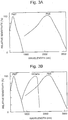
- Fig. 3A shows the wavelength-sensitivity characteristics of a PMT detector and PbS detector.
- both PMT and PbS detectors have low levels of sensitivity to the light within a wavelength range around 900 nm in which the two detectors are switched.
- Patent Literature 1 the idea of using three types of detectors including an InGaAs detector which has a high level of sensitivity to the light in the aforementioned wavelength range has been proposed (Patent Literature 1).
- Patent Literature 1 With this system, a wide range of wavelengths of light from 150 nm to 3000 nm can be detected with high levels of sensitivity, as shown in Fig. 3B .
- Fig. 4 shows one example, in which the third detector 12a is placed at a light detection window 13 formed at a position displaced from the polar points toward the side where the sample 4 is located.
- the intensity distribution of the diffuse reflected light within the detection field of the detector 12a is not equal to the intensity distribution within the detection fields of the two other detectors 10a and 11 a.
- the light incident on the detection surface of the third detector 12a originates from a detection field where the light has a different intensity distribution from the light incident on the two other detectors 10a and 11 a. Therefore, a measurement discrepancy occurs when the detector used for the measurement is switched from the first detector 10a, or second detector 11 a, to the third one 12a.
- the problem to be solved by the present invention is to provide an integrating sphere and spectrometer which is configured to reduce the measurement discrepancy which occurs when light emitted from a sample is detected with a plurality of detectors via the integrating sphere.
- the integrating sphere for a spectrometer according to the present invention developed for solving the previously described problem includes:
- Each of the windows may be either a simple through hole or an opening covered with a plate made of a material that allows the passage of light within a range of wavelengths that need to be detected.
- the detector attached to the first detector attachment section and the one attached to the second detector attachment section have the same detection fields. Accordingly, the two detectors attached to the integrating sphere according to the present invention receive light from the detection fields which have equal intensity distributions, so that the measurement discrepancy which occurs when the two detectors are switched is reduced.
- the first detector attachment section and/or the second detector attachment section may preferably be provided with a position adjuster for adjusting the position of the detectors so as to make the detection fields of the detectors attached to the first detector attachment section and the second detector attachment section coincide with each other.
- the position adjuster may be a mechanism for providing a larger attachment distance from the outer surface of the integrating sphere for the detector having a larger detection angle among the detectors attached to the first and second attachment sections, or a mechanism for providing a smaller attachment distance from the outer surface of the integrating sphere for the detector having a smaller detection angle.
- the present invention also provides a spectrometer including any of the previously described modes of the integrating sphere with a detector attached to each detector attachment section.
- a spectrometer including any of the previously described modes of the integrating sphere with a detector attached to each detector attachment section.
- a PMT detector, InGaAs detector and PbS detector can be used as the detectors.
- the detector attached to the first detector attachment section and the one attached to the second detector attachment section have the same detection fields. Accordingly, the two detectors attached to the integrating sphere according to the present invention receive light from the detection fields which have equal intensity distributions, so that the measurement discrepancy which occurs when the two detectors are switched is reduced.
- Fig. 5 shows the configuration of the main components of one embodiment of the spectrometer including an integrating sphere according to the present invention.
- the present embodiment is a spectrometer in which light generated from a light source outside the integrating sphere is introduced through a light introduction window 2 into the sphere to irradiate a sample 4 with the light and detect diffuse light reflected by the sample 4.
- the X, Y and Z axes are defined in a similar manner to the previously described example, with the points of intersection of the Z axis and the integrating sphere referred to as the "polar points".
- the integrating sphere is provided with a light introduction window 2, light entrance window 3, as well as three light detection windows 10, 11 and 13.
- First, second and third detector attachment sections 10b, 13b and 11b are provided at the three light detection windows.
- the light detection windows 10 and 11 are located at the polar points, while the light detection window 13 is formed at a position displaced from the polar points toward the side closer to the sample 4.
- the first, second and third detectors 10a, 13 a and 11a are attached to the first, second and third detector attachment sections 10b, 13b and 11b, respectively.
- the spectrometer of the present embodiment is characterized in that the detector attachment sections allow the direction of the detector attached to each attachment section to be freely changed. In the spectrometer of the present embodiment, this feature is utilized so as to make the detection field of the detector 10a attached to the first detector attachment section coincide with that of the detector 13a attached to the second detector attachment section 13b. In the present embodiment, only the detector 13a at the second detector attachment section 13b is attached in a different direction from the conventional case ( Fig. 4 ). It is also possible to change the attachment direction of the detectors at both the first and second detector attachment sections 10b and 13b so as to make the detection fields of the two detectors 10a and 13a attached to the two attachment sections coincide with each other. As already explained with reference to Fig. 2 , the detection field of the detector 11a attached to the third detector attachment section 11 b is equal to the detection field of the first detector 10a.
- the detection fields of the detector 10a and 13a in the present embodiment are made to coincide with each other, so that these detectors receive light from detection fields having equal intensity distributions. Therefore, the measurement discrepancy becomes smaller than in the case of a conventional spectrometer in which the intensity of the light from a sample is measured with a detector located at a position different from the polar points.
- the number of detectors may be arbitrarily changed, because the position of the detector attachment sections in the integrating sphere according to the present invention is not limited to the polar points.
- the measurement discrepancy which occurs when the detectors are switched in the spectrometer of the present embodiment has been investigated and compared with the measurement discrepancy which occurs in a conventional spectrometer.
- three types of detectors PMT detector, InGaAs detector and PbS detector
- the detector-switching operation was performed at wavelengths of 830 nm and 1650 nm.
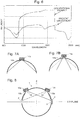
- the result shown in Fig. 6 demonstrates that the measurement discrepancy can be dramatically reduced by using the spectrometer of the present embodiment.
- Figs. 7A and 7B show one example of the detector attachment section 14b having the position adjuster. Specifically, Fig. 7A shows the detection angle of the detector 14a attached in the same manner as in the previous embodiment, while Fig. 7B shows the detection angle of the detector 14a attached at a farther position from the outer surface of the integrating sphere. As can be seen in Figs.
- the effective detection angle can be changed by moving the detector 10a closer to or farther from the outer surface of the integrating sphere using the position adjuster.
- the detection fields of a plurality of types of detectors can be made to coincide with each other even those detectors have different detection angles.
- the attachment sections are configured so that the direction of the detector attached to each attachment section is freely changeable (moveable). If the types of detectors to be used are previously specified, the detector attachment sections may be configured so that the detectors attached to those sections will be fixed in such directions where their detection fields coincide with each other.
- At least one detector attachment section is provided at one of the polar points.
- the previously described embodiment is a spectrometer in which light generated from a light source outside the integrating sphere is introduced through a light introduction window to irradiate a sample with the light and detect diffuse light reflected by the sample.
- the integrating sphere according to the present invention can be used in various forms of spectrometers, such as a spectrometer in which light generated from a light source outside the integrating sphere is cast onto a sample and the light transmitted through the sample is introduced into the integrating sphere and thereby detected, as well as a spectrometer in which the light source is located within the integrating sphere.
- an integrating sphere with no light introduction window 2 is appropriately used.
Landscapes
- Physics & Mathematics (AREA)
- Spectroscopy & Molecular Physics (AREA)
- General Physics & Mathematics (AREA)
- Investigating Or Analysing Materials By Optical Means (AREA)
- Photometry And Measurement Of Optical Pulse Characteristics (AREA)
Abstract
Description
- The present invention relates to an integrating sphere used in a spectrometer or similar device, as well as a spectrometer using such an integrating sphere. More specifically, it relates to an integrating sphere that can be suitably used in the case of performing a spectrometric measurement using a plurality of detectors, as well as a spectrometer provided with such an integrating sphere.
- In the case where a measurement of light reflected by or transmitted through a sample is performed with a spectrometer, if the light is diffuse light, an integrating sphere is used to maximally introduce the light from the sample into a detector. An integrating sphere has a light entrance window and light detection window. The light from the sample is introduced through the light entrance window into the integrating sphere. This sphere internally has a reflection surface with a high level of reflectance. The light which has entered the integrating sphere is reflected by the inner surface of the integrating sphere, to eventually pass through the light detection window and fall onto the detector (a portion of the light directly reaches the detector). In the case where the irradiation of a sample with light is performed via the integrating sphere, a light introduction window is additionally formed in the integrating sphere, allowing light from an external source to be introduced through this light introduction window into the sphere and cast onto the sample.
- In the case of performing a spectrometric measurement over a wide range of wavelengths, two or more types of detectors having different wavelength-sensitivity characteristics are normally used. Conventionally, two types of detectors have been used for such purposes, i.e. a PMT detector, which has a high level of sensitivity to ultraviolet-visible light, and a PbS detector, which has a high level of sensitivity to near infrared radiation.
-
Figs. 1 and 2 show anintegrating sphere 1 with a light introduction window, which allows for the use of two types of detectors and has the following elements arranged: alight introduction window 2,light entrance window 3, twolight detection windows detectors Fig. 1 , alight entrance window 3 is formed in the integratingsphere 1. With the straight line connecting the center of theintegrating sphere 1 and thelight entrance window 3 defined as the X axis, and one arbitrary straight line which passes through the center of theintegrating sphere 1 perpendicularly to the X axis defined as the Z axis, thelight detection windows detectors integrating sphere 1 perpendicularly to both of the X and Z axes defined as the Y axis, thelight introduction window 2 is placed at a position on the X-Y plane opposite from thelight entrance window 3 with respect to the center of theintegrating sphere 1, being slightly displaced from the point of intersection of the X axis and the integratingsphere 1. This displacement is made in order that the directly reflected (mirror-reflected) ray of the light which is reflected by the surface of thesample 4 and enters theintegrating sphere 1 through thelight entrance window 3 will not exit (escape) through thelight introduction window 2 to the outside. - The light which has been generated from the light source and has entered the integrating
sphere 1 through thelight introduction window 2 is cast onto the sample surface through thelight entrance window 3. After undergoing absorption at specific wavelengths to the sample, the light is reflected through thelight entrance window 3 into theintegrating sphere 1. After being reflected on the inner surface of theintegrating sphere 1, the light falls onto the detectors through the light detection windows (a portion of the light directly reaches those detectors). The intensity of the reflected light changes with the reflection angle, with its intensity distribution expressed as a cosine distribution which is symmetrical with respect to the X-Y plane. Since the two types ofdetectors detectors detectors - Patent Literature 1:
JP 2006-23284 A -
Fig. 3A shows the wavelength-sensitivity characteristics of a PMT detector and PbS detector. As can be seen in the figure, both PMT and PbS detectors have low levels of sensitivity to the light within a wavelength range around 900 nm in which the two detectors are switched. To overcome this problem, the idea of using three types of detectors including an InGaAs detector which has a high level of sensitivity to the light in the aforementioned wavelength range has been proposed (Patent Literature 1). With this system, a wide range of wavelengths of light from 150 nm to 3000 nm can be detected with high levels of sensitivity, as shown inFig. 3B . - In the case of using three types of
detectors detectors remaining detector 12a must be arranged at a position different from the polar points.Fig. 4 shows one example, in which thethird detector 12a is placed at alight detection window 13 formed at a position displaced from the polar points toward the side where thesample 4 is located. In this case, the intensity distribution of the diffuse reflected light within the detection field of thedetector 12a is not equal to the intensity distribution within the detection fields of the twoother detectors third detector 12a originates from a detection field where the light has a different intensity distribution from the light incident on the twoother detectors first detector 10a, orsecond detector 11 a, to thethird one 12a. - The problem to be solved by the present invention is to provide an integrating sphere and spectrometer which is configured to reduce the measurement discrepancy which occurs when light emitted from a sample is detected with a plurality of detectors via the integrating sphere.
- The integrating sphere for a spectrometer according to the present invention developed for solving the previously described problem includes:
- a) an integrating spherical body with a light entrance window for allowing an entry of light emitted from a sample, a first light detection window, and a second light detection window;
- b) a first detector attachment section located on the outside of the first light detection window; and
- c) a second detector attachment section located on the outside of the second light detection window in such a manner that the detection field of a detector to be attached to the second detector attachment section coincides with the detection field of a detector to be attached to the first detector attachment section.
- Each of the windows may be either a simple through hole or an opening covered with a plate made of a material that allows the passage of light within a range of wavelengths that need to be detected.
- In the integrating sphere according to the present invention, the detector attached to the first detector attachment section and the one attached to the second detector attachment section have the same detection fields. Accordingly, the two detectors attached to the integrating sphere according to the present invention receive light from the detection fields which have equal intensity distributions, so that the measurement discrepancy which occurs when the two detectors are switched is reduced.
- In the integrating sphere according to the present invention, the first detector attachment section and/or the second detector attachment section may preferably be provided with a position adjuster for adjusting the position of the detectors so as to make the detection fields of the detectors attached to the first detector attachment section and the second detector attachment section coincide with each other.
- The position adjuster may be a mechanism for providing a larger attachment distance from the outer surface of the integrating sphere for the detector having a larger detection angle among the detectors attached to the first and second attachment sections, or a mechanism for providing a smaller attachment distance from the outer surface of the integrating sphere for the detector having a smaller detection angle. With this configuration, even in the case of using two types of detectors having different viewing angles, their detection fields can be made to coincide with each other to reduce the measurement discrepancy.
- The present invention also provides a spectrometer including any of the previously described modes of the integrating sphere with a detector attached to each detector attachment section. For example, a PMT detector, InGaAs detector and PbS detector can be used as the detectors.
- In the integrating sphere according to the present invention, the detector attached to the first detector attachment section and the one attached to the second detector attachment section have the same detection fields. Accordingly, the two detectors attached to the integrating sphere according to the present invention receive light from the detection fields which have equal intensity distributions, so that the measurement discrepancy which occurs when the two detectors are switched is reduced.
-
-
Fig. 1 is a configuration diagram showing the main components of a spectrometer including a conventional integrating sphere. -
Fig. 2 is a diagram illustrating the arrangement of the detectors in a spectrometer including a conventional integrating sphere. -
Fig. 3A and 3B are diagrams showing the wavelength-sensitivity characteristics of a PMT detector, PbS detector and InGaAs detector. -
Fig. 4 is a diagram illustrating the detection fields of the detectors in a spectrometer including a conventional integrating sphere. -
Fig. 5 a configuration diagram showing the main components of a spectrometer including an integrating sphere according to the present invention. -
Fig. 6 is a diagram showing a comparison of the measurement discrepancy between the case where the spectrometer of the present embodiment is used and the case where a conventional spectrometer is used. -
Figs. 7A and 7B are diagrams illustrating one embodiment of the detector attachment section having a position adjuster. -
Fig. 8 is a diagram illustrating a variation of the integrating sphere according to the present invention. - An embodiment of the spectrometer including an integrating sphere according to the present invention is hereinafter described with reference to
Figs. 5-8 . -
Fig. 5 shows the configuration of the main components of one embodiment of the spectrometer including an integrating sphere according to the present invention. The present embodiment is a spectrometer in which light generated from a light source outside the integrating sphere is introduced through alight introduction window 2 into the sphere to irradiate asample 4 with the light and detect diffuse light reflected by thesample 4. In the present embodiment, the X, Y and Z axes are defined in a similar manner to the previously described example, with the points of intersection of the Z axis and the integrating sphere referred to as the "polar points". - In the spectrometer of the present embodiment, the integrating sphere is provided with a
light introduction window 2,light entrance window 3, as well as threelight detection windows detector attachment sections light detection windows light detection window 13 is formed at a position displaced from the polar points toward the side closer to thesample 4. The first, second andthird detectors detector attachment sections - The spectrometer of the present embodiment is characterized in that the detector attachment sections allow the direction of the detector attached to each attachment section to be freely changed. In the spectrometer of the present embodiment, this feature is utilized so as to make the detection field of the
detector 10a attached to the first detector attachment section coincide with that of thedetector 13a attached to the seconddetector attachment section 13b. In the present embodiment, only thedetector 13a at the seconddetector attachment section 13b is attached in a different direction from the conventional case (Fig. 4 ). It is also possible to change the attachment direction of the detectors at both the first and seconddetector attachment sections detectors Fig. 2 , the detection field of thedetector 11a attached to the third detector attachment section 11 b is equal to the detection field of thefirst detector 10a. - As just described, the detection fields of the
detector - The measurement discrepancy which occurs when the detectors are switched in the spectrometer of the present embodiment has been investigated and compared with the measurement discrepancy which occurs in a conventional spectrometer. In any of these spectrometers, three types of detectors (PMT detector, InGaAs detector and PbS detector) were used and the detector-switching operation was performed at wavelengths of 830 nm and 1650 nm. The result shown in
Fig. 6 demonstrates that the measurement discrepancy can be dramatically reduced by using the spectrometer of the present embodiment. - In the previous embodiment, detectors with the same viewing angles are used. It is also possible to use a plurality of detectors having different detection angles. In this case, a detector attachment section having a position adjuster for adjusting the position of the detector is used in order to make the detection fields of the detectors coincide with each other.
Figs. 7A and 7B show one example of thedetector attachment section 14b having the position adjuster. Specifically,Fig. 7A shows the detection angle of thedetector 14a attached in the same manner as in the previous embodiment, whileFig. 7B shows the detection angle of thedetector 14a attached at a farther position from the outer surface of the integrating sphere. As can be seen inFigs. 7A and 7B , the effective detection angle can be changed by moving thedetector 10a closer to or farther from the outer surface of the integrating sphere using the position adjuster. With this mechanism, the detection fields of a plurality of types of detectors can be made to coincide with each other even those detectors have different detection angles. - The previous embodiments are mere examples and can be appropriately changed within the spirit of the present invention.
- The previously described embodiment is concerned with the case where the attachment sections are configured so that the direction of the detector attached to each attachment section is freely changeable (moveable). If the types of detectors to be used are previously specified, the detector attachment sections may be configured so that the detectors attached to those sections will be fixed in such directions where their detection fields coincide with each other.
- In the previously described embodiment, at least one detector attachment section is provided at one of the polar points. However, it is not always necessary to provide the detector attachment sections at the polar points. For example, it is possible to provide detector attachment sections as indicated by
numerals Fig. 8 , with thedetectors - The previously described embodiment is a spectrometer in which light generated from a light source outside the integrating sphere is introduced through a light introduction window to irradiate a sample with the light and detect diffuse light reflected by the sample. However, the integrating sphere according to the present invention can be used in various forms of spectrometers, such as a spectrometer in which light generated from a light source outside the integrating sphere is cast onto a sample and the light transmitted through the sample is introduced into the integrating sphere and thereby detected, as well as a spectrometer in which the light source is located within the integrating sphere. Depending on the configuration of the spectrometer, an integrating sphere with no
light introduction window 2 is appropriately used. -
- 1
- Integrating Sphere
- 2
- Light Introduction Window
- 3
- Light Entrance Window
- 4
- Sample
- 10, 11, 12, 13, 14, 15
- Light Detection Window
- 10a, 11a, 12a, 13a, 14a, 15a
- Detector
- 10b, 11b, 12b, 13b, 14b, 15b
- Detector Attachment Section
Claims (3)
- An integrating sphere for a spectrometer, comprising:a) an integrating spherical body with a light entrance window for allowing an entry of light emitted from a sample, a first light detection window, and a second light detection window;b) a first detector attachment section located on an outside of the first light detection window; andc) a second detector attachment section located on an outside of the second light detection window in such a manner that a detection field of a detector to be attached to the second detector attachment section coincides with a detection field of a detector to be attached to the first detector attachment section.
- The integrating sphere for a spectrometer according to claim 1, wherein the first detector attachment section and/or the second detector attachment section is provided with a position adjuster for adjusting a position of the detectors so as to make the detection fields of the detectors attached to the first detector attachment section and the second detector attachment section coincide with each other.
- A spectrometer, comprising the integrating sphere according to claim 1 or 2.
Applications Claiming Priority (1)
| Application Number | Priority Date | Filing Date | Title |
|---|---|---|---|
| PCT/JP2014/059660 WO2015151233A1 (en) | 2014-04-01 | 2014-04-01 | Spectrometer and integrating sphere |
Publications (3)
| Publication Number | Publication Date |
|---|---|
| EP3128302A1 true EP3128302A1 (en) | 2017-02-08 |
| EP3128302A4 EP3128302A4 (en) | 2017-04-26 |
| EP3128302B1 EP3128302B1 (en) | 2023-08-02 |
Family
ID=54239600
Family Applications (1)
| Application Number | Title | Priority Date | Filing Date |
|---|---|---|---|
| EP14888029.7A Active EP3128302B1 (en) | 2014-04-01 | 2014-04-01 | Spectrometer and integrating sphere |
Country Status (5)
| Country | Link |
|---|---|
| US (1) | US10094711B2 (en) |
| EP (1) | EP3128302B1 (en) |
| JP (1) | JP6330900B2 (en) |
| CN (1) | CN106164632B (en) |
| WO (1) | WO2015151233A1 (en) |
Families Citing this family (2)
| Publication number | Priority date | Publication date | Assignee | Title |
|---|---|---|---|---|
| JP6227067B1 (en) | 2016-07-25 | 2017-11-08 | 浜松ホトニクス株式会社 | Optical measuring device |
| US10302529B2 (en) * | 2017-03-17 | 2019-05-28 | Fluke Corporation | Optical connector polarity and loss measurement using an integrating sphere-equipped optical measurement device |
Family Cites Families (14)
| Publication number | Priority date | Publication date | Assignee | Title |
|---|---|---|---|---|
| US4932779A (en) * | 1989-01-05 | 1990-06-12 | Byk Gardner, Inc. | Color measuring instrument with integrating sphere |
| US5369481A (en) | 1992-05-08 | 1994-11-29 | X-Rite, Incorporated | Portable spectrophotometer |
| JP3464824B2 (en) * | 1994-03-07 | 2003-11-10 | 株式会社リコー | Optical measuring device |
| US6424413B1 (en) * | 1998-06-12 | 2002-07-23 | Gretagmacbeth Llc | Multi-channel integrating sphere |
| US6675030B2 (en) * | 2000-08-21 | 2004-01-06 | Euro-Celtique, S.A. | Near infrared blood glucose monitoring system |
| JP2002062189A (en) * | 2000-08-24 | 2002-02-28 | Shimadzu Corp | Spectrometer detector, integrating sphere measuring device and spectrophotometer using the same |
| JP3318912B1 (en) * | 2001-08-28 | 2002-08-26 | スガ試験機株式会社 | Tristimulus direct reading colorimeter |
| JP4622673B2 (en) * | 2004-06-11 | 2011-02-02 | 株式会社島津製作所 | UV Visible Near Infrared Spectrophotometer Detector |
| JP2009175026A (en) * | 2008-01-25 | 2009-08-06 | Shimadzu Corp | UV Visible Near Infrared Spectrophotometer Detector |
| CN201311325Y (en) * | 2008-11-19 | 2009-09-16 | 中国计量科学研究院 | Integrating sphere and optical measuring system using same |
| JP2010261847A (en) | 2009-05-08 | 2010-11-18 | Konica Minolta Holdings Inc | System for evaluating electronic display medium |
| JP2012027353A (en) | 2010-07-27 | 2012-02-09 | Alps Electric Co Ltd | Optical communication apparatus and assembling method thereof |
| JP5479543B2 (en) * | 2012-07-19 | 2014-04-23 | 大塚電子株式会社 | Optical property measuring device |
| JP6185864B2 (en) * | 2013-06-07 | 2017-08-23 | 本田技研工業株式会社 | Integrating sphere |
-
2014
- 2014-04-01 JP JP2016511251A patent/JP6330900B2/en active Active
- 2014-04-01 EP EP14888029.7A patent/EP3128302B1/en active Active
- 2014-04-01 WO PCT/JP2014/059660 patent/WO2015151233A1/en not_active Ceased
- 2014-04-01 CN CN201480077731.4A patent/CN106164632B/en active Active
- 2014-04-01 US US15/300,329 patent/US10094711B2/en active Active
Also Published As
| Publication number | Publication date |
|---|---|
| EP3128302A4 (en) | 2017-04-26 |
| CN106164632B (en) | 2019-06-21 |
| WO2015151233A1 (en) | 2015-10-08 |
| US10094711B2 (en) | 2018-10-09 |
| JPWO2015151233A1 (en) | 2017-04-13 |
| EP3128302B1 (en) | 2023-08-02 |
| JP6330900B2 (en) | 2018-05-30 |
| CN106164632A (en) | 2016-11-23 |
| US20170146398A1 (en) | 2017-05-25 |
Similar Documents
| Publication | Publication Date | Title |
|---|---|---|
| KR101988697B1 (en) | Portable spectrometer | |
| US8259294B2 (en) | Method and device for measuring optical characteristic variables of transparent, scattering measurement objects | |
| ES2203658T3 (en) | PROCEDURE AND DEVICE FOR MEASUREMENTS OF AND REMISSION AND SPECTRAL TRANSMISSION. | |
| US20140332687A1 (en) | Optical system, terahertz emission microscope, and method of manufacturing a device | |
| US10088363B2 (en) | Biometric sensor and biometric analysis system including the same | |
| JP2012255781A (en) | Device for referenced measurement of reflected light and method for calibrating the device | |
| US10180352B2 (en) | Measuring light source, and measuring system for detecting a reflection spectrum | |
| EP3470818A1 (en) | Microparticle measuring device and microparticle analysis method | |
| WO2009119542A1 (en) | Standard light source device | |
| EP3128302A1 (en) | Spectrometer and integrating sphere | |
| US9429472B2 (en) | Illumination device and reflection characteristic measuring device | |
| DE102007061213A1 (en) | Arrangement for determining the reflectance of a sample | |
| KR102504516B1 (en) | Device for laser absorption spectroscopy analysis | |
| US20160341659A1 (en) | Spectrometer and gas analyzer | |
| CN211927089U (en) | Time division multiplexing double-beam photometric device | |
| DE102014214721A1 (en) | Arrangement for spatially and wavelength-resolved detection of light radiation emitted by at least one OLED or LED | |
| US11054365B2 (en) | Microscopic analysis device | |
| JP2005172568A (en) | Optical apparatus and measuring apparatus having the same | |
| EP4411344A1 (en) | Optical measuring device | |
| CN111504463A (en) | A Time Division Multiplexing Dual Beam Photometric Device | |
| CN106197665B (en) | Spectrum test device and its test method |
Legal Events
| Date | Code | Title | Description |
|---|---|---|---|
| STAA | Information on the status of an ep patent application or granted ep patent |
Free format text: STATUS: THE INTERNATIONAL PUBLICATION HAS BEEN MADE |
|
| PUAI | Public reference made under article 153(3) epc to a published international application that has entered the european phase |
Free format text: ORIGINAL CODE: 0009012 |
|
| STAA | Information on the status of an ep patent application or granted ep patent |
Free format text: STATUS: REQUEST FOR EXAMINATION WAS MADE |
|
| 17P | Request for examination filed |
Effective date: 20161102 |
|
| AK | Designated contracting states |
Kind code of ref document: A1 Designated state(s): AL AT BE BG CH CY CZ DE DK EE ES FI FR GB GR HR HU IE IS IT LI LT LU LV MC MK MT NL NO PL PT RO RS SE SI SK SM TR |
|
| AX | Request for extension of the european patent |
Extension state: BA ME |
|
| A4 | Supplementary search report drawn up and despatched |
Effective date: 20170327 |
|
| RIC1 | Information provided on ipc code assigned before grant |
Ipc: G01J 3/02 20060101AFI20170321BHEP Ipc: G01J 1/02 20060101ALI20170321BHEP |
|
| DAX | Request for extension of the european patent (deleted) | ||
| STAA | Information on the status of an ep patent application or granted ep patent |
Free format text: STATUS: EXAMINATION IS IN PROGRESS |
|
| 17Q | First examination report despatched |
Effective date: 20200708 |
|
| GRAP | Despatch of communication of intention to grant a patent |
Free format text: ORIGINAL CODE: EPIDOSNIGR1 |
|
| STAA | Information on the status of an ep patent application or granted ep patent |
Free format text: STATUS: GRANT OF PATENT IS INTENDED |
|
| INTG | Intention to grant announced |
Effective date: 20230228 |
|
| RAP3 | Party data changed (applicant data changed or rights of an application transferred) |
Owner name: SHIMADZU CORPORATION |
|
| GRAS | Grant fee paid |
Free format text: ORIGINAL CODE: EPIDOSNIGR3 |
|
| GRAA | (expected) grant |
Free format text: ORIGINAL CODE: 0009210 |
|
| STAA | Information on the status of an ep patent application or granted ep patent |
Free format text: STATUS: THE PATENT HAS BEEN GRANTED |
|
| AK | Designated contracting states |
Kind code of ref document: B1 Designated state(s): AL AT BE BG CH CY CZ DE DK EE ES FI FR GB GR HR HU IE IS IT LI LT LU LV MC MK MT NL NO PL PT RO RS SE SI SK SM TR |
|
| REG | Reference to a national code |
Ref country code: GB Ref legal event code: FG4D |
|
| REG | Reference to a national code |
Ref country code: CH Ref legal event code: EP |
|
| REG | Reference to a national code |
Ref country code: DE Ref legal event code: R096 Ref document number: 602014087867 Country of ref document: DE |
|
| REG | Reference to a national code |
Ref country code: IE Ref legal event code: FG4D |
|
| REG | Reference to a national code |
Ref country code: LT Ref legal event code: MG9D |
|
| REG | Reference to a national code |
Ref country code: NL Ref legal event code: MP Effective date: 20230802 |
|
| REG | Reference to a national code |
Ref country code: AT Ref legal event code: MK05 Ref document number: 1595287 Country of ref document: AT Kind code of ref document: T Effective date: 20230802 |
|
| PG25 | Lapsed in a contracting state [announced via postgrant information from national office to epo] |
Ref country code: GR Free format text: LAPSE BECAUSE OF FAILURE TO SUBMIT A TRANSLATION OF THE DESCRIPTION OR TO PAY THE FEE WITHIN THE PRESCRIBED TIME-LIMIT Effective date: 20231103 |
|
| PG25 | Lapsed in a contracting state [announced via postgrant information from national office to epo] |
Ref country code: IS Free format text: LAPSE BECAUSE OF FAILURE TO SUBMIT A TRANSLATION OF THE DESCRIPTION OR TO PAY THE FEE WITHIN THE PRESCRIBED TIME-LIMIT Effective date: 20231202 |
|
| PG25 | Lapsed in a contracting state [announced via postgrant information from national office to epo] |
Ref country code: SE Free format text: LAPSE BECAUSE OF FAILURE TO SUBMIT A TRANSLATION OF THE DESCRIPTION OR TO PAY THE FEE WITHIN THE PRESCRIBED TIME-LIMIT Effective date: 20230802 Ref country code: RS Free format text: LAPSE BECAUSE OF FAILURE TO SUBMIT A TRANSLATION OF THE DESCRIPTION OR TO PAY THE FEE WITHIN THE PRESCRIBED TIME-LIMIT Effective date: 20230802 Ref country code: PT Free format text: LAPSE BECAUSE OF FAILURE TO SUBMIT A TRANSLATION OF THE DESCRIPTION OR TO PAY THE FEE WITHIN THE PRESCRIBED TIME-LIMIT Effective date: 20231204 Ref country code: NO Free format text: LAPSE BECAUSE OF FAILURE TO SUBMIT A TRANSLATION OF THE DESCRIPTION OR TO PAY THE FEE WITHIN THE PRESCRIBED TIME-LIMIT Effective date: 20231102 Ref country code: NL Free format text: LAPSE BECAUSE OF FAILURE TO SUBMIT A TRANSLATION OF THE DESCRIPTION OR TO PAY THE FEE WITHIN THE PRESCRIBED TIME-LIMIT Effective date: 20230802 Ref country code: LV Free format text: LAPSE BECAUSE OF FAILURE TO SUBMIT A TRANSLATION OF THE DESCRIPTION OR TO PAY THE FEE WITHIN THE PRESCRIBED TIME-LIMIT Effective date: 20230802 Ref country code: LT Free format text: LAPSE BECAUSE OF FAILURE TO SUBMIT A TRANSLATION OF THE DESCRIPTION OR TO PAY THE FEE WITHIN THE PRESCRIBED TIME-LIMIT Effective date: 20230802 Ref country code: IS Free format text: LAPSE BECAUSE OF FAILURE TO SUBMIT A TRANSLATION OF THE DESCRIPTION OR TO PAY THE FEE WITHIN THE PRESCRIBED TIME-LIMIT Effective date: 20231202 Ref country code: HR Free format text: LAPSE BECAUSE OF FAILURE TO SUBMIT A TRANSLATION OF THE DESCRIPTION OR TO PAY THE FEE WITHIN THE PRESCRIBED TIME-LIMIT Effective date: 20230802 Ref country code: GR Free format text: LAPSE BECAUSE OF FAILURE TO SUBMIT A TRANSLATION OF THE DESCRIPTION OR TO PAY THE FEE WITHIN THE PRESCRIBED TIME-LIMIT Effective date: 20231103 Ref country code: FI Free format text: LAPSE BECAUSE OF FAILURE TO SUBMIT A TRANSLATION OF THE DESCRIPTION OR TO PAY THE FEE WITHIN THE PRESCRIBED TIME-LIMIT Effective date: 20230802 Ref country code: AT Free format text: LAPSE BECAUSE OF FAILURE TO SUBMIT A TRANSLATION OF THE DESCRIPTION OR TO PAY THE FEE WITHIN THE PRESCRIBED TIME-LIMIT Effective date: 20230802 |
|
| PG25 | Lapsed in a contracting state [announced via postgrant information from national office to epo] |
Ref country code: PL Free format text: LAPSE BECAUSE OF FAILURE TO SUBMIT A TRANSLATION OF THE DESCRIPTION OR TO PAY THE FEE WITHIN THE PRESCRIBED TIME-LIMIT Effective date: 20230802 |
|
| PG25 | Lapsed in a contracting state [announced via postgrant information from national office to epo] |
Ref country code: ES Free format text: LAPSE BECAUSE OF FAILURE TO SUBMIT A TRANSLATION OF THE DESCRIPTION OR TO PAY THE FEE WITHIN THE PRESCRIBED TIME-LIMIT Effective date: 20230802 |
|
| PG25 | Lapsed in a contracting state [announced via postgrant information from national office to epo] |
Ref country code: SM Free format text: LAPSE BECAUSE OF FAILURE TO SUBMIT A TRANSLATION OF THE DESCRIPTION OR TO PAY THE FEE WITHIN THE PRESCRIBED TIME-LIMIT Effective date: 20230802 Ref country code: RO Free format text: LAPSE BECAUSE OF FAILURE TO SUBMIT A TRANSLATION OF THE DESCRIPTION OR TO PAY THE FEE WITHIN THE PRESCRIBED TIME-LIMIT Effective date: 20230802 Ref country code: ES Free format text: LAPSE BECAUSE OF FAILURE TO SUBMIT A TRANSLATION OF THE DESCRIPTION OR TO PAY THE FEE WITHIN THE PRESCRIBED TIME-LIMIT Effective date: 20230802 Ref country code: EE Free format text: LAPSE BECAUSE OF FAILURE TO SUBMIT A TRANSLATION OF THE DESCRIPTION OR TO PAY THE FEE WITHIN THE PRESCRIBED TIME-LIMIT Effective date: 20230802 Ref country code: DK Free format text: LAPSE BECAUSE OF FAILURE TO SUBMIT A TRANSLATION OF THE DESCRIPTION OR TO PAY THE FEE WITHIN THE PRESCRIBED TIME-LIMIT Effective date: 20230802 Ref country code: CZ Free format text: LAPSE BECAUSE OF FAILURE TO SUBMIT A TRANSLATION OF THE DESCRIPTION OR TO PAY THE FEE WITHIN THE PRESCRIBED TIME-LIMIT Effective date: 20230802 Ref country code: SK Free format text: LAPSE BECAUSE OF FAILURE TO SUBMIT A TRANSLATION OF THE DESCRIPTION OR TO PAY THE FEE WITHIN THE PRESCRIBED TIME-LIMIT Effective date: 20230802 |
|
| REG | Reference to a national code |
Ref country code: DE Ref legal event code: R097 Ref document number: 602014087867 Country of ref document: DE |
|
| PG25 | Lapsed in a contracting state [announced via postgrant information from national office to epo] |
Ref country code: IT Free format text: LAPSE BECAUSE OF FAILURE TO SUBMIT A TRANSLATION OF THE DESCRIPTION OR TO PAY THE FEE WITHIN THE PRESCRIBED TIME-LIMIT Effective date: 20230802 |
|
| PLBE | No opposition filed within time limit |
Free format text: ORIGINAL CODE: 0009261 |
|
| STAA | Information on the status of an ep patent application or granted ep patent |
Free format text: STATUS: NO OPPOSITION FILED WITHIN TIME LIMIT |
|
| 26N | No opposition filed |
Effective date: 20240503 |
|
| PG25 | Lapsed in a contracting state [announced via postgrant information from national office to epo] |
Ref country code: SI Free format text: LAPSE BECAUSE OF FAILURE TO SUBMIT A TRANSLATION OF THE DESCRIPTION OR TO PAY THE FEE WITHIN THE PRESCRIBED TIME-LIMIT Effective date: 20230802 |
|
| PG25 | Lapsed in a contracting state [announced via postgrant information from national office to epo] |
Ref country code: BG Free format text: LAPSE BECAUSE OF FAILURE TO SUBMIT A TRANSLATION OF THE DESCRIPTION OR TO PAY THE FEE WITHIN THE PRESCRIBED TIME-LIMIT Effective date: 20230802 |
|
| PG25 | Lapsed in a contracting state [announced via postgrant information from national office to epo] |
Ref country code: MC Free format text: LAPSE BECAUSE OF FAILURE TO SUBMIT A TRANSLATION OF THE DESCRIPTION OR TO PAY THE FEE WITHIN THE PRESCRIBED TIME-LIMIT Effective date: 20230802 |
|
| PG25 | Lapsed in a contracting state [announced via postgrant information from national office to epo] |
Ref country code: MC Free format text: LAPSE BECAUSE OF FAILURE TO SUBMIT A TRANSLATION OF THE DESCRIPTION OR TO PAY THE FEE WITHIN THE PRESCRIBED TIME-LIMIT Effective date: 20230802 Ref country code: BG Free format text: LAPSE BECAUSE OF FAILURE TO SUBMIT A TRANSLATION OF THE DESCRIPTION OR TO PAY THE FEE WITHIN THE PRESCRIBED TIME-LIMIT Effective date: 20230802 |
|
| REG | Reference to a national code |
Ref country code: CH Ref legal event code: PL |
|
| PG25 | Lapsed in a contracting state [announced via postgrant information from national office to epo] |
Ref country code: LU Free format text: LAPSE BECAUSE OF NON-PAYMENT OF DUE FEES Effective date: 20240401 |
|
| GBPC | Gb: european patent ceased through non-payment of renewal fee |
Effective date: 20240401 |
|
| REG | Reference to a national code |
Ref country code: BE Ref legal event code: MM Effective date: 20240430 |
|
| PG25 | Lapsed in a contracting state [announced via postgrant information from national office to epo] |
Ref country code: LU Free format text: LAPSE BECAUSE OF NON-PAYMENT OF DUE FEES Effective date: 20240401 |
|
| PG25 | Lapsed in a contracting state [announced via postgrant information from national office to epo] |
Ref country code: BE Free format text: LAPSE BECAUSE OF NON-PAYMENT OF DUE FEES Effective date: 20240430 |
|
| PG25 | Lapsed in a contracting state [announced via postgrant information from national office to epo] |
Ref country code: GB Free format text: LAPSE BECAUSE OF NON-PAYMENT OF DUE FEES Effective date: 20240401 |
|
| PG25 | Lapsed in a contracting state [announced via postgrant information from national office to epo] |
Ref country code: FR Free format text: LAPSE BECAUSE OF NON-PAYMENT OF DUE FEES Effective date: 20240430 |
|
| PG25 | Lapsed in a contracting state [announced via postgrant information from national office to epo] |
Ref country code: GB Free format text: LAPSE BECAUSE OF NON-PAYMENT OF DUE FEES Effective date: 20240401 Ref country code: FR Free format text: LAPSE BECAUSE OF NON-PAYMENT OF DUE FEES Effective date: 20240430 Ref country code: BE Free format text: LAPSE BECAUSE OF NON-PAYMENT OF DUE FEES Effective date: 20240430 Ref country code: CH Free format text: LAPSE BECAUSE OF NON-PAYMENT OF DUE FEES Effective date: 20240430 |
|
| PG25 | Lapsed in a contracting state [announced via postgrant information from national office to epo] |
Ref country code: IE Free format text: LAPSE BECAUSE OF NON-PAYMENT OF DUE FEES Effective date: 20240401 |
|
| PGFP | Annual fee paid to national office [announced via postgrant information from national office to epo] |
Ref country code: DE Payment date: 20250305 Year of fee payment: 12 |
|
| PG25 | Lapsed in a contracting state [announced via postgrant information from national office to epo] |
Ref country code: CY Free format text: LAPSE BECAUSE OF FAILURE TO SUBMIT A TRANSLATION OF THE DESCRIPTION OR TO PAY THE FEE WITHIN THE PRESCRIBED TIME-LIMIT; INVALID AB INITIO Effective date: 20140401 |
|
| PG25 | Lapsed in a contracting state [announced via postgrant information from national office to epo] |
Ref country code: HU Free format text: LAPSE BECAUSE OF FAILURE TO SUBMIT A TRANSLATION OF THE DESCRIPTION OR TO PAY THE FEE WITHIN THE PRESCRIBED TIME-LIMIT; INVALID AB INITIO Effective date: 20140401 |
|
| PG25 | Lapsed in a contracting state [announced via postgrant information from national office to epo] |
Ref country code: TR Free format text: LAPSE BECAUSE OF FAILURE TO SUBMIT A TRANSLATION OF THE DESCRIPTION OR TO PAY THE FEE WITHIN THE PRESCRIBED TIME-LIMIT Effective date: 20230802 |