EP3128212B1 - Instrument for measuring the flowrate of a fluid - Google Patents
Instrument for measuring the flowrate of a fluid Download PDFInfo
- Publication number
- EP3128212B1 EP3128212B1 EP16182119.4A EP16182119A EP3128212B1 EP 3128212 B1 EP3128212 B1 EP 3128212B1 EP 16182119 A EP16182119 A EP 16182119A EP 3128212 B1 EP3128212 B1 EP 3128212B1
- Authority
- EP
- European Patent Office
- Prior art keywords
- upstream
- downstream
- chamber
- fluid
- instrument according
- Prior art date
- Legal status (The legal status is an assumption and is not a legal conclusion. Google has not performed a legal analysis and makes no representation as to the accuracy of the status listed.)
- Active
Links
- 239000012530 fluid Substances 0.000 title claims description 30
- 238000011144 upstream manufacturing Methods 0.000 claims description 37
- 238000001514 detection method Methods 0.000 claims description 5
- 238000007599 discharging Methods 0.000 claims description 2
- 238000005259 measurement Methods 0.000 description 23
- 238000009434 installation Methods 0.000 description 3
- 238000009825 accumulation Methods 0.000 description 2
- 229910000831 Steel Inorganic materials 0.000 description 1
- 230000005540 biological transmission Effects 0.000 description 1
- 238000009530 blood pressure measurement Methods 0.000 description 1
- 230000006835 compression Effects 0.000 description 1
- 238000007906 compression Methods 0.000 description 1
- 238000001816 cooling Methods 0.000 description 1
- 230000001419 dependent effect Effects 0.000 description 1
- 238000006073 displacement reaction Methods 0.000 description 1
- 238000005516 engineering process Methods 0.000 description 1
- 238000010438 heat treatment Methods 0.000 description 1
- 239000012535 impurity Substances 0.000 description 1
- 239000000463 material Substances 0.000 description 1
- 239000010959 steel Substances 0.000 description 1
Images

Classifications
-
- G—PHYSICS
- G01—MEASURING; TESTING
- G01F—MEASURING VOLUME, VOLUME FLOW, MASS FLOW OR LIQUID LEVEL; METERING BY VOLUME
- G01F15/00—Details of, or accessories for, apparatus of groups G01F1/00 - G01F13/00 insofar as such details or appliances are not adapted to particular types of such apparatus
- G01F15/005—Valves
-
- F—MECHANICAL ENGINEERING; LIGHTING; HEATING; WEAPONS; BLASTING
- F16—ENGINEERING ELEMENTS AND UNITS; GENERAL MEASURES FOR PRODUCING AND MAINTAINING EFFECTIVE FUNCTIONING OF MACHINES OR INSTALLATIONS; THERMAL INSULATION IN GENERAL
- F16K—VALVES; TAPS; COCKS; ACTUATING-FLOATS; DEVICES FOR VENTING OR AERATING
- F16K15/00—Check valves
- F16K15/02—Check valves with guided rigid valve members
- F16K15/06—Check valves with guided rigid valve members with guided stems
- F16K15/063—Check valves with guided rigid valve members with guided stems the valve being loaded by a spring
-
- F—MECHANICAL ENGINEERING; LIGHTING; HEATING; WEAPONS; BLASTING
- F16—ENGINEERING ELEMENTS AND UNITS; GENERAL MEASURES FOR PRODUCING AND MAINTAINING EFFECTIVE FUNCTIONING OF MACHINES OR INSTALLATIONS; THERMAL INSULATION IN GENERAL
- F16K—VALVES; TAPS; COCKS; ACTUATING-FLOATS; DEVICES FOR VENTING OR AERATING
- F16K27/00—Construction of housing; Use of materials therefor
- F16K27/02—Construction of housing; Use of materials therefor of lift valves
- F16K27/0209—Check valves or pivoted valves
-
- G—PHYSICS
- G01—MEASURING; TESTING
- G01F—MEASURING VOLUME, VOLUME FLOW, MASS FLOW OR LIQUID LEVEL; METERING BY VOLUME
- G01F1/00—Measuring the volume flow or mass flow of fluid or fluent solid material wherein the fluid passes through a meter in a continuous flow
- G01F1/05—Measuring the volume flow or mass flow of fluid or fluent solid material wherein the fluid passes through a meter in a continuous flow by using mechanical effects
- G01F1/34—Measuring the volume flow or mass flow of fluid or fluent solid material wherein the fluid passes through a meter in a continuous flow by using mechanical effects by measuring pressure or differential pressure
- G01F1/36—Measuring the volume flow or mass flow of fluid or fluent solid material wherein the fluid passes through a meter in a continuous flow by using mechanical effects by measuring pressure or differential pressure the pressure or differential pressure being created by the use of flow constriction
- G01F1/40—Details of construction of the flow constriction devices
- G01F1/44—Venturi tubes
Definitions
- the present invention relates to an instrument for measuring the flowrate of a fluid flowing inside a pipe.
- EP O 593 164 A1 discloses a flow meter having a conduit with a constriction in which a contoured plug is situated, the plug being axially displaceable, under a pressure difference across the constriction, against the biasing action of resilient means; the resilient means act between the plug and an abutment to thereby vary the flow cross-section of the constriction.
- the flow-rate measurement is effected by measurement means responsive to the force applied by the resilient means on the abutment, for providing a signal representing the flow rate through the conduit.
- a differential pressure transducer for detecting a difference in pressure which occurs between the inside of a first chamber upstream of the constriction, and the inside of a conduit downstream of the constriction is provided.
- US 2002/101355 A1 discloses a flow sensor device that has a check valve comprising a moving plate for moving in response to fluid flow through the sensor and a biasing means for biasing the plate towards the sensor inlet; in order to measure the flow rate inside the device, a sensor means is provided for sensing the movement of the moving plate and creating a signal related to its location.
- the moving plate is composed of a magnetizable material and the sensor means comprises a steel sensor disposed adjacent to a path traveled by the moving plate for sensing the location of the moving plate.
- EP 1 835 209 An example of a prior art device that uses a pressure measurement to measure flow rate through a pipe is known from EP 1 835 209 , on which the preamble of claim 1 is based and which describes a tri-functional valve able to measure a differential pressure value ⁇ p by means of a measuring instrument connected to a Venturi tube arranged between a check valve and a shut-off valve.
- the instrument for measuring the differential pressure is connected, using well-established technology, upstream, to the first portion of the Venturi tube which has a larger cross-section and, downstream, to the central portion of the Venturi tube which has a narrow cross-section.
- the measuring instrument detects the value of ⁇ p corresponding to the variation in pressure which occurs in the movement of the fluid as it passes from the larger cross-section to a smaller cross-section of the Venturi tube.
- the instrument therefore measures only the value of ⁇ p generated by the Venturi tube alone which is proportional to the square flowrate Q 2 .
- Such a configuration wherein ⁇ p value measured across the Venturi is used for indirect measurement of the flowrate, results in limited rangeability (turndown ratio) values corresponding to typical values of the Venturi tube which are close to 5:1 for the ratio ⁇ ⁇ p max ⁇ ⁇ pmin between a maximum value ⁇ pmax and a minimum value ⁇ pmin which the instrument is able to measure.
- the instrument for measurement of the flowrate may be: direct, for example by means of electronic display or by means of the indicator of a flowmeter; indirect, for example by means of an auxiliary reading instrument, such as the electronic instruments designed to read the values recorded by balancing valves; or reading performed by turbine instruments, which generate an electromagnet pulse with each revolution of the turbine driven by the fluid.
- the calibrated scale for displaying the measurement is passed through by the fluid which tends to introduce impurities inside it, resulting, within a short period of time, in dirt accumulation that makes it more or less impossible to read the flowrate measurement, with consequent errors in regulation by the user.
- the technical problem which is posed, therefore, is that of providing an instrument for measuring the flowrate of a fluid flowing inside a pipe which is able to cover very wide measurement ranges embracing low to high flowrate values.
- the instrument should have small dimensions, be easy and inexpensive to produce and assemble and be able to be easily installed at any user location using normal standardized connection means.
- the instrument for measuring the flowrate of a fluid substantially comprises:
- the movement of the closing member in the longitudinal direction X-X is preferably guided by a projection 42 which is integral with the front downstream surface of the body 41 of the valve 40 and inside which the shank 43b slides.
- a spring 44 is coaxially arranged between the guiding projection 42 and the head 43a of the closing member and is calibrated to provide a suitable resistance to sliding of the closing member and therefore to opening of the upstream aperture 21a.
- the set of portions forming the chamber 30 simulates substantially a Venturi tube, the upstream aperture of which is connected to the downstream opening 41b of the check valve and the downstream aperture of which forms the outlet for fluid F out from the measuring instrument.
- the detection device 50 is connected by means of an upstream pipe 51 to the upstream chamber 20 and by means of a downstream pipe to the said central cylindrical portion 33 of the second chamber 30 and comprises a dial 53, of the analog type in the example shown, for indicating the pressure difference value ⁇ p detected.
- the instrument is able to detect the variation in pressure across the assembly composed of the check valve and the Venturi tube.
- the displacement of the closing member 43 varies depending on the flowrate of the fluid flowing inside the valve.
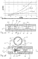
- the graph in Fig. 2 As can be seen from the graph in Fig.
- the locus of the points for the pressure difference values is a curve ⁇ p always resulting from a combination of the curve ⁇ pb, which expresses the head loss occurring across the upstream check valve 40, and the curve ⁇ pa, which instead expresses the variation in pressure referable to the downstream portion 30 which simulates the Venturi tube; what is significant is that, despite the fact that the resultant curve ⁇ p represents a combination of the two values, at low flowrates the contribution to the measurement made by the Venturi tube is negligible, while at high flowrates the contribution provided by the fluid flowing through the check valve becomes negligible.
- a second embodiment of the measuring instrument according to the invention is envisaged, said embodiment being in this case realized by means of a check valve 140 and a tubular portion 130 simulating the Venturi tube, said valve and tubular portion being independent of each other and, during use, coaxially connected together as shown in Fig. 4b for example by means of a male/female thread connection 150.
- the check valve comprises a substantially cylindrical body 41 which has an upstream opening 41a, a downstream opening 41b and a suitable outer diameter d 40 .
- the cylindrical body 41 has, formed inside it, an upstream chamber 20 and also contains a closing member 43 which is displaceable in both senses of the longitudinal direction X-X and comprises a head 43a, designed to interfere with and close/open the upstream opening 41a of the valve, and a shank 43b integral with the head 43a.
- a closing member 43 which is displaceable in both senses of the longitudinal direction X-X and comprises a head 43a, designed to interfere with and close/open the upstream opening 41a of the valve, and a shank 43b integral with the head 43a.
- the movement of the closing member in the longitudinal direction X-X is preferably guided by a baffle 142 integral with the side surface of the body 41, as shown in Fig. 4a , or by means of a projection 42 - similar to that described for Fig. 1 - inside which the shank 43b slides, as shown in Fig. 4b .
- a spring 44 calibrated to provide a suitable resistance to sliding of the closing member and therefore opening of the upstream aperture 41a, is coaxially arranged between the guide baffle 142 and the head 43a of the closing member.
- the tubular portion 130 has at least a succession of portions 32,33,34 which are entirely similar to those of the first embodiment and which are therefore mentioned here and not further described.
- the instrument is in this case also completed by a display dial 53 connected by means of the respective upstream pipe 51 and downstream pipe 52 to the upstream chamber 20 of the check valve 40 and to the central portion 33 of the tubular element 130.
- measurement display dials which are for example digital instead of analog
Description
- The present invention relates to an instrument for measuring the flowrate of a fluid flowing inside a pipe.
- It is known in the sector of hydro-thermo sanitary installations for both heating and cooling applications that continuous attempts are being made to improve said installations in terms of their efficiency and comfort for the user.
- It is also known that possibilities of obtaining such an improvement are dependent on the possibility of carrying out measurements of the values of parameters indicative of the real operation of the installation, the most important measurement parameters including: the temperature, pressure and flowrate of the fluid.
- As regards in particular the flowrate measurement instruments of various types are known and these, although fulfilling their function, nevertheless have drawbacks which limit their possible applications since they are costly, have large dimensions and offer a poor level of precision. This in turn gives rise to head losses and in particular a low value for the maximum to minimum flowrate ratio which can be measured by the instrument (otherwise known as "rangeability" or "turndown ratio").
- This means that in practice the known measurement instruments are necessarily specialized for a specific measurement range determined by the respective full scale value.
- Consequently an instrument which is suitable for measuring high flowrates is not suitable for measuring low flowrates and vice versa; this results in a consequent need for an increase in the types of instruments which can be used, the storage facilities, the specific choices made during the design stage and therefore the final cost of the measurement devices.
-
EP O 593 164 A1 - In order to allow meter calibration to be checked in service without disturbing any internal components of the meter, a differential pressure transducer for detecting a difference in pressure which occurs between the inside of a first chamber upstream of the constriction, and the inside of a conduit downstream of the constriction is provided.
-
US 2002/101355 A1 discloses a flow sensor device that has a check valve comprising a moving plate for moving in response to fluid flow through the sensor and a biasing means for biasing the plate towards the sensor inlet; in order to measure the flow rate inside the device, a sensor means is provided for sensing the movement of the moving plate and creating a signal related to its location. The moving plate is composed of a magnetizable material and the sensor means comprises a steel sensor disposed adjacent to a path traveled by the moving plate for sensing the location of the moving plate. - An example of a prior art device that uses a pressure measurement to measure flow rate through a pipe is known from
EP 1 835 209 , on which the preamble of claim 1 is based and which describes a tri-functional valve able to measure a differential pressure value Δp by means of a measuring instrument connected to a Venturi tube arranged between a check valve and a shut-off valve. - In
EP 1 835 209 the instrument for measuring the differential pressure is connected, using well-established technology, upstream, to the first portion of the Venturi tube which has a larger cross-section and, downstream, to the central portion of the Venturi tube which has a narrow cross-section. In this way the measuring instrument detects the value of Δp corresponding to the variation in pressure which occurs in the movement of the fluid as it passes from the larger cross-section to a smaller cross-section of the Venturi tube. The instrument therefore measures only the value of Δp generated by the Venturi tube alone which is proportional to the square flowrate Q2 . Such a configuration, wherein Δp value measured across the Venturi is used for indirect measurement of the flowrate, results in limited rangeability (turndown ratio) values corresponding to typical values of the Venturi tube which are close to 5:1 for the ratio
- This limited rangeability is decidedly inadequate, for example, in the case of typical hydro-thermo sanitary applications for which an adequate value of the ratio is 25:1.
- Moreover increasing the rangeability of the measurement chain described above would result in a significant increase in the cost of the entire instrument.
- It is also necessary to take into account the type and quality of the reading made by the instrument for measurement of the flowrate which may be: direct, for example by means of electronic display or by means of the indicator of a flowmeter; indirect, for example by means of an auxiliary reading instrument, such as the electronic instruments designed to read the values recorded by balancing valves; or reading performed by turbine instruments, which generate an electromagnet pulse with each revolution of the turbine driven by the fluid.
- As regards particular devices for measuring the flowrate of a flow, such as flowmeters, there is the further problem arising from the fact that the display scales are typically small and difficult to read.
- In addition to the above, there is also the drawback that the calibrated scale for displaying the measurement is passed through by the fluid which tends to introduce impurities inside it, resulting, within a short period of time, in dirt accumulation that makes it more or less impossible to read the flowrate measurement, with consequent errors in regulation by the user.
- The technical problem which is posed, therefore, is that of providing an instrument for measuring the flowrate of a fluid flowing inside a pipe which is able to cover very wide measurement ranges embracing low to high flowrate values.
- In connection with this problem it is also desirable that such an instrument should not give rise to excessive head losses in the flow so as not to reduce its efficiency and should not be subject to soiling which over time reduces the legibility of the measurement display scale.
- Moreover the instrument should have small dimensions, be easy and inexpensive to produce and assemble and be able to be easily installed at any user location using normal standardized connection means.
- These results are obtained according to the present invention by an instrument for measuring the flowrate of a fluid according to the features of Claim 1.
- Further details may be obtained from the following description of non-limiting examples of embodiment of the subject matter of the present invention, provided with reference to the accompanying drawings, in which:
-
Figure 1 : shows a cross-section, along a diametral vertical plane, of the measuring instrument according to the invention during measurement of a low flowrate; -
Figure 2 : shows a cross-section, similar to that ofFig. 1 , with the instrument during measurement of high flowrates; -
Figure 3 : shows a graph of the measurements obtained with the instrument according to the invention; and -
Figures 4a, 4b : show a second example of embodiment of the measuring instrument according to the invention. - As shown in
Fig. 1 and assuming solely for the sake of easier description and without a limiting meaning a longitudinal direction X-X, corresponding to the lengthwise extension of the instrument and the direction of flow, and an upstream part corresponding to the part for entry into the same of the fluid Fin and a downstream part opposite to the preceding part and corresponding to the part for outflow of the fluid Fout, the instrument for measuring the flowrate of a fluid according to the invention substantially comprises: - A
tubular element 10 with a given overall length L divided along the longitudinal direction X-X into two portions with a respective length L0 and L1 arranged in series relative to each other and comprising from upstream to downstream:- •) a first
cylindrical chamber 20 with a given inner diameter d20 extending between an upstream opening 21a and adownstream opening 21b; - •) a
check valve 40 comprising a substantiallycylindrical body 41 with an outer diameter d40 such that it may be coaxially inserted inside thechamber 20; thecylindrical body 41 has anupstream opening 41a, communicating with thefirst chamber 20, and adownstream opening 41b; the valve houses internally aclosing member 43 displaceable in both senses of the longitudinal direction X-X and comprising ahead 43a, designed to interfere so as to close/open theupstream opening 41a of the valve, and ashank 43b integral with thehead 43a.
- •) a first
- The movement of the closing member in the longitudinal direction X-X is preferably guided by a
projection 42 which is integral with the front downstream surface of thebody 41 of thevalve 40 and inside which theshank 43b slides. - A
spring 44 is coaxially arranged between the guidingprojection 42 and thehead 43a of the closing member and is calibrated to provide a suitable resistance to sliding of the closing member and therefore to opening of theupstream aperture 21a. - A
second chamber 30 which, from upstream to downstream, comprises at least:- a second portion having a
frustoconical form 32 with its greater base situated upstream, - a third, central,
cylindrical portion 33 with a cross-section substantially corresponding to that of the smaller base of thesecond portion 32; - a
fourth portion 34 with a frustoconical cross-section having its larger base situated downstream.
- a second portion having a
- The following is also preferably provided:
- a first
cylindrical portion 31 with a given cross-section, and/or - a
fifth portion 35 with a cylindrical cross-section for discharging the fluid Fout. - The set of portions forming the
chamber 30 simulates substantially a Venturi tube, the upstream aperture of which is connected to thedownstream opening 41b of the check valve and the downstream aperture of which forms the outlet for fluid Fout from the measuring instrument. - A device for detecting a difference in pressure Δp which occurs between the firstupstream chamber 20, communicating with thecheck valve 40 upstream opening and the centralcylindrical portion 33 of thesecond chamber 30. - The
detection device 50 is connected by means of anupstream pipe 51 to theupstream chamber 20 and by means of a downstream pipe to the said centralcylindrical portion 33 of thesecond chamber 30 and comprises adial 53, of the analog type in the example shown, for indicating the pressure difference value Δp detected. - With this arrangement of the connections for the
upstream pipe 51 anddownstream pipe 52, the instrument is able to detect the variation in pressure across the assembly composed of the check valve and the Venturi tube. - With this configuration the operating principle of the flowrate measuring instrument according to the invention is as follows:
- the
tubular portion 10 is inserted inside the piping section (not shown) for which the flowrate of the fluid flowing inside it must be determined; - the fluid flow Fin is opened by means of an upstream or downstream device - not shown and not forming part of the invention - so that it enters into the
first chamber 20 and then into thecheck valve 40 with a pressure P1 which produces a thrust on theclosing member 43 which overcomes the force of thespring 44 and opens the check valve; - once the check valve is open the fluid flows there through and, flowing out from the
downstream opening 41b, enters into thesecond portion 30 of the instrument where it undergoes compression/expansion determined by the dimensions of theportions cylindrical portion 33 connected to thedownstream pipe 52 of thedetection device 50 is determined. - The
detection device 50 detects the pressure difference Δp=P2-P1 across the assembly formed by the check valve plus Venturi tube, providing an indication of its value on thedial 53. - With the indication of the value Δp it is possible in a conventional manner well-established in the technical reference sector to refer to the graph (
Fig. 3 ) showing Flowrate Q versus Pressure Difference Δp, associated with the measuring instrument, and thereby obtain with precision the flowrate of the fluid flowing inside the piping. - The displacement of the
closing member 43 varies depending on the flowrate of the fluid flowing inside the valve. - As shown in
Fig. 2 , any increase in the flowrate of the fluid Fin produces a greater thrust on theclosing member 43 which, overcoming the resistance of thespring 44, moves downstream, opening more thecheck valve 40 so as to allow the greater fluid flow Fin to pass through; at the same time an increase of the value of Δp=P2-P1 occurs and the measurement thereof is shown on theanalog dial 53. As can be seen from the graph inFig. 3 , the locus of the points for the pressure difference values is a curve Δp always resulting from a combination of the curve Δpb, which expresses the head loss occurring across theupstream check valve 40, and the curve Δpa, which instead expresses the variation in pressure referable to thedownstream portion 30 which simulates the Venturi tube; what is significant is that, despite the fact that the resultant curve Δp represents a combination of the two values, at low flowrates the contribution to the measurement made by the Venturi tube is negligible, while at high flowrates the contribution provided by the fluid flowing through the check valve becomes negligible. - As shown in
Figs. 4a,4b (in which parts corresponding to the previous embodiment maintain the same reference number) a second embodiment of the measuring instrument according to the invention is envisaged, said embodiment being in this case realized by means of acheck valve 140 and atubular portion 130 simulating the Venturi tube, said valve and tubular portion being independent of each other and, during use, coaxially connected together as shown inFig. 4b for example by means of a male/female thread connection 150. - In detail the check valve comprises a substantially
cylindrical body 41 which has anupstream opening 41a, adownstream opening 41b and a suitable outer diameter d40. - The
cylindrical body 41 has, formed inside it, anupstream chamber 20 and also contains aclosing member 43 which is displaceable in both senses of the longitudinal direction X-X and comprises ahead 43a, designed to interfere with and close/open theupstream opening 41a of the valve, and ashank 43b integral with thehead 43a. - The movement of the closing member in the longitudinal direction X-X is preferably guided by a
baffle 142 integral with the side surface of thebody 41, as shown inFig. 4a , or by means of a projection 42 - similar to that described forFig. 1 - inside which theshank 43b slides, as shown inFig. 4b . - A
spring 44, calibrated to provide a suitable resistance to sliding of the closing member and therefore opening of theupstream aperture 41a, is coaxially arranged between theguide baffle 142 and thehead 43a of the closing member. - The
tubular portion 130 has at least a succession ofportions display dial 53 connected by means of the respectiveupstream pipe 51 anddownstream pipe 52 to theupstream chamber 20 of thecheck valve 40 and to thecentral portion 33 of thetubular element 130. - As a result a same measuring instrument constructed in a simple, low-cost and reliable manner is able to measure with suitable precision the flowrate of a fluid inside piping even where there exist considerable differences between low flowrates and high flowrates, thereby solving the technical problem of the prior art which requires different instruments with different full scale values in order to measure flowrates which differ greatly from each other.
- Moreover, display of the measurement remains always clear and precise over time, since the dial of the detection device is not passed through by the fluid, avoiding the accumulation of dirt on the said dial.
- Although described in the context of a number of embodiments and a number of preferred examples of embodiment of the invention it is understood that equivalent variants may be introduced into the constructional design of the measuring instrument which may be calibrated so that the graduated scale of the dial indicates directly - and therefore more easily for the user - the value of the flowrate measured.
- In addition the following may be differently envisaged: measurement display dials, which are for example digital instead of analog; dimensions for the lengths L,L1,L2, and diameters d20,d40 of the
chamber 20 and thevalve 40, respectively, and for the lengths and cross-sections of the different portions of thechamber 30 simulating a Venturi tube, and/or the introduction of differential transducers for the remote transmission of the signal representing the measurement of the flowrate. - It is understood therefore that these variants may be implemented without departing from the scope of protection of the present patent as defined by the claims which follow.
Claims (9)
- Instrument for measuring the flowrate of a fluid (Fin, Fout) flowing inside a pipe from upstream to downstream along a longitudinal flow direction (X-X), comprising:- a check valve (40;140) and a tubular element (30;130) simulating, in use, a Venturi tube, said valve and element being coaxially connected together, respectively, from upstream to downstream in the longitudinal direction (X-X) of flow of the fluid;- a device (50) arranged for detecting a difference in pressure (Δp) which occurs between the inside of a first chamber (20) and the inside of a central cylindrical portion (33) of the tubular element (30;130), characterized in that said first chamber (20) is a chamber upstream of the check valve (40;140) and communicating therewith.
- Instrument according to Claim 1, characterized in that said check valve (40;140) comprises a substantially cylindrical body (41;141) of suitable outer diameter provided with an upstream opening (41a), communicating with said first upstream chamber (20;120), and a downstream opening (41b), a closing member (43) being inserted inside the valve and being displaceable in both senses of the longitudinal direction (X-X) under the thrusting action of the fluid or the thrusting action of a spring (44) in the opposite direction.
- Instrument according to Claim 1 or 2, characterized in that said tubular element (30;130) comprises at least:• a second portion having a frustoconical form (32) with its greater base situated upstream and smaller base situated downstream,• a third, central, cylindrical portion (33) with a cross-section substantially corresponding to that of the smaller base of the second frustoconical portion (31),• a fourth portion (34) with a frustoconical cross-section having its larger base situated downstream, said portions being arranged in series along the longitudinal direction (X-X).
- Instrument according to Claim 3, characterized in that said tubular element (30;130) comprises:- a first cylindrical portion (310) with a given cross-section, arranged upstream of the said second frustoconical portion (32).
- Instrument according to Claim 3 or 4, characterized in that said tubular element (30;130) comprises a fifth portion (35) with a cylindrical cross-section, arranged downstream of the said fourth frustoconical portion (34), for discharging the fluid (Fout).
- Instrument according to any one of the preceding claims, characterized in that said detection device (50) is connected by means of an upstream pipe (51) to the upstream chamber (20) and by means of a downstream pipe (52) to the said central cylindrical portion (33) of the tubular element (30;130).
- Instrument according to any one of the preceding claims, characterized in that said measuring device comprises a dial (53) showing the value of the difference in pressure (Δp) detected.
- Instrument according to any one of Claims 1 to 7, characterized in that it comprises:- a tubular element (10) extending in a longitudinal direction (X-X) of flow of the fluid from upstream to downstream, having a given overall length (L) and being divided up along the longitudinal direction (X-X) into two portions (20,30) of respective length (L0,L1) arranged relative to each other in series from upstream to downstream in the direction of flow of the fluid and respectively comprising:• a first chamber (20) of given internal diameter (d20) extending in the longitudinal direction (X-X) between an upstream opening (21a) and a downstream opening (21b); the check valve (40) being coaxially inserted in the first chamber (20);• a second chamber (30) which from upstream to downstream comprises at least three portions (32,33,34) of varying cross-section which together are designed to simulate a Venturi tube.
- Instrument according to the preceding claim, characterized in that said check valve (40) comprises a substantially cylindrical body (41) with an outer diameter (d40) such that it may be coaxially inserted inside the chamber (20).
Applications Claiming Priority (1)
| Application Number | Priority Date | Filing Date | Title |
|---|---|---|---|
| ITUB2015A002823A ITUB20152823A1 (en) | 2015-08-04 | 2015-08-04 | MEASUREMENT INSTRUMENT OF THE FLOW OF A FLUID |
Publications (2)
| Publication Number | Publication Date |
|---|---|
| EP3128212A1 EP3128212A1 (en) | 2017-02-08 |
| EP3128212B1 true EP3128212B1 (en) | 2019-11-06 |
Family
ID=54884135
Family Applications (1)
| Application Number | Title | Priority Date | Filing Date |
|---|---|---|---|
| EP16182119.4A Active EP3128212B1 (en) | 2015-08-04 | 2016-08-01 | Instrument for measuring the flowrate of a fluid |
Country Status (2)
| Country | Link |
|---|---|
| EP (1) | EP3128212B1 (en) |
| IT (1) | ITUB20152823A1 (en) |
Families Citing this family (3)
| Publication number | Priority date | Publication date | Assignee | Title |
|---|---|---|---|---|
| CN108931272B (en) * | 2017-05-27 | 2021-12-31 | 深圳市美好创亿医疗科技股份有限公司 | Porous differential pressure flow sensor and pulmonary function instrument |
| CN111982213B (en) * | 2020-08-20 | 2022-02-11 | 中国核动力研究设计院 | Flow measurement method and system for nuclear reactor simulation fuel assembly |
| CN114704947B (en) * | 2022-03-31 | 2023-06-16 | 同舟蓝海(北京)控股有限公司 | Air quantity regulating valve capable of accurately measuring air quantity |
Family Cites Families (5)
| Publication number | Priority date | Publication date | Assignee | Title |
|---|---|---|---|---|
| US3438392A (en) * | 1967-05-19 | 1969-04-15 | Bastian Blessing Co | Multi-purpose liquid transfer valve |
| DE69329748D1 (en) * | 1992-10-15 | 2001-01-18 | Spirax Sarco Ltd | Throttle flow meter |
| US6741179B2 (en) * | 1998-06-17 | 2004-05-25 | Richard Young | Apparatus for flow detection, measurement and control and system for use of same |
| JP4824949B2 (en) * | 2005-06-03 | 2011-11-30 | サーパス工業株式会社 | Orifice member, differential pressure flow meter using the same, and flow rate adjusting device |
| US7445025B2 (en) * | 2006-03-13 | 2008-11-04 | Itt Manufacturing Enterprises, Inc | Combination valve |
-
2015
- 2015-08-04 IT ITUB2015A002823A patent/ITUB20152823A1/en unknown
-
2016
- 2016-08-01 EP EP16182119.4A patent/EP3128212B1/en active Active
Non-Patent Citations (1)
| Title |
|---|
| None * |
Also Published As
| Publication number | Publication date |
|---|---|
| ITUB20152823A1 (en) | 2017-02-04 |
| EP3128212A1 (en) | 2017-02-08 |
Similar Documents
| Publication | Publication Date | Title |
|---|---|---|
| EP3276311B1 (en) | Balancing valve for adjusting the distribution of fluids in multiple pipes | |
| JP3554347B2 (en) | Flowmeter | |
| CN102016519B (en) | Method for generating a diagnostic from a deviation of a flow meter parameter | |
| EP3128212B1 (en) | Instrument for measuring the flowrate of a fluid | |
| US8683875B2 (en) | Beta ratio changer for flow measurement devices | |
| US5333496A (en) | In-line parallel proportionally partitioned by-pass metering device and method | |
| US20070157738A1 (en) | Flow meter with fluid lens | |
| US9068867B2 (en) | Angled port differential pressure flow meter | |
| US4254664A (en) | Flow meters | |
| US6923074B2 (en) | Ball valve with flow-rate gauge incorporated directly in the ball | |
| JP6706748B2 (en) | Method for manufacturing critical nozzle type gas flowmeter and method for adjusting test gas flowmeter | |
| US3287971A (en) | Flowmeter | |
| WO2010002432A1 (en) | Insertable ultrasonic meter and method | |
| CN104165664B (en) | Pitot bar integrated mass flow meter | |
| US20100043567A1 (en) | Measuring arrangement for flow measurement in a channel | |
| CN105784292A (en) | Piston air leakage amount measurement system based on balanced flow meter | |
| JPH09101186A (en) | Pitot-tube type mass flowmeter | |
| JP3607041B2 (en) | Flow control valve device | |
| KR0171633B1 (en) | Flow meter having a contoured plug and resilient means | |
| KR102629898B1 (en) | Vortex generation and detection apparatus for vortex type flow meter | |
| US11815377B2 (en) | Vortex flowmeter providing extended flow rate measurement | |
| CN209992027U (en) | Plug-in pitot tube flowmeter | |
| RU2293291C2 (en) | Device for measuring flow of free-flowing substances | |
| US20240019285A1 (en) | Vortex flowmeter providing extended flow rate measurement | |
| CN208458805U (en) | Flow measurement device and valve for liquid |
Legal Events
| Date | Code | Title | Description |
|---|---|---|---|
| PUAI | Public reference made under article 153(3) epc to a published international application that has entered the european phase |
Free format text: ORIGINAL CODE: 0009012 |
|
| STAA | Information on the status of an ep patent application or granted ep patent |
Free format text: STATUS: THE APPLICATION HAS BEEN PUBLISHED |
|
| AK | Designated contracting states |
Kind code of ref document: A1 Designated state(s): AL AT BE BG CH CY CZ DE DK EE ES FI FR GB GR HR HU IE IS IT LI LT LU LV MC MK MT NL NO PL PT RO RS SE SI SK SM TR |
|
| AX | Request for extension of the european patent |
Extension state: BA ME |
|
| STAA | Information on the status of an ep patent application or granted ep patent |
Free format text: STATUS: REQUEST FOR EXAMINATION WAS MADE |
|
| 17P | Request for examination filed |
Effective date: 20170731 |
|
| RBV | Designated contracting states (corrected) |
Designated state(s): AL AT BE BG CH CY CZ DE DK EE ES FI FR GB GR HR HU IE IS IT LI LT LU LV MC MK MT NL NO PL PT RO RS SE SI SK SM TR |
|
| GRAP | Despatch of communication of intention to grant a patent |
Free format text: ORIGINAL CODE: EPIDOSNIGR1 |
|
| STAA | Information on the status of an ep patent application or granted ep patent |
Free format text: STATUS: GRANT OF PATENT IS INTENDED |
|
| INTG | Intention to grant announced |
Effective date: 20190531 |
|
| GRAS | Grant fee paid |
Free format text: ORIGINAL CODE: EPIDOSNIGR3 |
|
| GRAA | (expected) grant |
Free format text: ORIGINAL CODE: 0009210 |
|
| STAA | Information on the status of an ep patent application or granted ep patent |
Free format text: STATUS: THE PATENT HAS BEEN GRANTED |
|
| AK | Designated contracting states |
Kind code of ref document: B1 Designated state(s): AL AT BE BG CH CY CZ DE DK EE ES FI FR GB GR HR HU IE IS IT LI LT LU LV MC MK MT NL NO PL PT RO RS SE SI SK SM TR |
|
| REG | Reference to a national code |
Ref country code: GB Ref legal event code: FG4D |
|
| REG | Reference to a national code |
Ref country code: CH Ref legal event code: EP Ref country code: AT Ref legal event code: REF Ref document number: 1199169 Country of ref document: AT Kind code of ref document: T Effective date: 20191115 |
|
| REG | Reference to a national code |
Ref country code: IE Ref legal event code: FG4D |
|
| REG | Reference to a national code |
Ref country code: DE Ref legal event code: R096 Ref document number: 602016023635 Country of ref document: DE |
|
| REG | Reference to a national code |
Ref country code: NL Ref legal event code: MP Effective date: 20191106 |
|
| REG | Reference to a national code |
Ref country code: LT Ref legal event code: MG4D |
|
| PG25 | Lapsed in a contracting state [announced via postgrant information from national office to epo] |
Ref country code: NO Free format text: LAPSE BECAUSE OF FAILURE TO SUBMIT A TRANSLATION OF THE DESCRIPTION OR TO PAY THE FEE WITHIN THE PRESCRIBED TIME-LIMIT Effective date: 20200206 Ref country code: GR Free format text: LAPSE BECAUSE OF FAILURE TO SUBMIT A TRANSLATION OF THE DESCRIPTION OR TO PAY THE FEE WITHIN THE PRESCRIBED TIME-LIMIT Effective date: 20200207 Ref country code: PL Free format text: LAPSE BECAUSE OF FAILURE TO SUBMIT A TRANSLATION OF THE DESCRIPTION OR TO PAY THE FEE WITHIN THE PRESCRIBED TIME-LIMIT Effective date: 20191106 Ref country code: LV Free format text: LAPSE BECAUSE OF FAILURE TO SUBMIT A TRANSLATION OF THE DESCRIPTION OR TO PAY THE FEE WITHIN THE PRESCRIBED TIME-LIMIT Effective date: 20191106 Ref country code: SE Free format text: LAPSE BECAUSE OF FAILURE TO SUBMIT A TRANSLATION OF THE DESCRIPTION OR TO PAY THE FEE WITHIN THE PRESCRIBED TIME-LIMIT Effective date: 20191106 Ref country code: FI Free format text: LAPSE BECAUSE OF FAILURE TO SUBMIT A TRANSLATION OF THE DESCRIPTION OR TO PAY THE FEE WITHIN THE PRESCRIBED TIME-LIMIT Effective date: 20191106 Ref country code: BG Free format text: LAPSE BECAUSE OF FAILURE TO SUBMIT A TRANSLATION OF THE DESCRIPTION OR TO PAY THE FEE WITHIN THE PRESCRIBED TIME-LIMIT Effective date: 20200206 Ref country code: PT Free format text: LAPSE BECAUSE OF FAILURE TO SUBMIT A TRANSLATION OF THE DESCRIPTION OR TO PAY THE FEE WITHIN THE PRESCRIBED TIME-LIMIT Effective date: 20200306 Ref country code: NL Free format text: LAPSE BECAUSE OF FAILURE TO SUBMIT A TRANSLATION OF THE DESCRIPTION OR TO PAY THE FEE WITHIN THE PRESCRIBED TIME-LIMIT Effective date: 20191106 Ref country code: LT Free format text: LAPSE BECAUSE OF FAILURE TO SUBMIT A TRANSLATION OF THE DESCRIPTION OR TO PAY THE FEE WITHIN THE PRESCRIBED TIME-LIMIT Effective date: 20191106 |
|
| PG25 | Lapsed in a contracting state [announced via postgrant information from national office to epo] |
Ref country code: IS Free format text: LAPSE BECAUSE OF FAILURE TO SUBMIT A TRANSLATION OF THE DESCRIPTION OR TO PAY THE FEE WITHIN THE PRESCRIBED TIME-LIMIT Effective date: 20200306 Ref country code: HR Free format text: LAPSE BECAUSE OF FAILURE TO SUBMIT A TRANSLATION OF THE DESCRIPTION OR TO PAY THE FEE WITHIN THE PRESCRIBED TIME-LIMIT Effective date: 20191106 Ref country code: RS Free format text: LAPSE BECAUSE OF FAILURE TO SUBMIT A TRANSLATION OF THE DESCRIPTION OR TO PAY THE FEE WITHIN THE PRESCRIBED TIME-LIMIT Effective date: 20191106 |
|
| PG25 | Lapsed in a contracting state [announced via postgrant information from national office to epo] |
Ref country code: AL Free format text: LAPSE BECAUSE OF FAILURE TO SUBMIT A TRANSLATION OF THE DESCRIPTION OR TO PAY THE FEE WITHIN THE PRESCRIBED TIME-LIMIT Effective date: 20191106 |
|
| PG25 | Lapsed in a contracting state [announced via postgrant information from national office to epo] |
Ref country code: ES Free format text: LAPSE BECAUSE OF FAILURE TO SUBMIT A TRANSLATION OF THE DESCRIPTION OR TO PAY THE FEE WITHIN THE PRESCRIBED TIME-LIMIT Effective date: 20191106 Ref country code: CZ Free format text: LAPSE BECAUSE OF FAILURE TO SUBMIT A TRANSLATION OF THE DESCRIPTION OR TO PAY THE FEE WITHIN THE PRESCRIBED TIME-LIMIT Effective date: 20191106 Ref country code: RO Free format text: LAPSE BECAUSE OF FAILURE TO SUBMIT A TRANSLATION OF THE DESCRIPTION OR TO PAY THE FEE WITHIN THE PRESCRIBED TIME-LIMIT Effective date: 20191106 Ref country code: EE Free format text: LAPSE BECAUSE OF FAILURE TO SUBMIT A TRANSLATION OF THE DESCRIPTION OR TO PAY THE FEE WITHIN THE PRESCRIBED TIME-LIMIT Effective date: 20191106 Ref country code: DK Free format text: LAPSE BECAUSE OF FAILURE TO SUBMIT A TRANSLATION OF THE DESCRIPTION OR TO PAY THE FEE WITHIN THE PRESCRIBED TIME-LIMIT Effective date: 20191106 |
|
| REG | Reference to a national code |
Ref country code: DE Ref legal event code: R097 Ref document number: 602016023635 Country of ref document: DE |
|
| REG | Reference to a national code |
Ref country code: AT Ref legal event code: MK05 Ref document number: 1199169 Country of ref document: AT Kind code of ref document: T Effective date: 20191106 |
|
| PG25 | Lapsed in a contracting state [announced via postgrant information from national office to epo] |
Ref country code: SM Free format text: LAPSE BECAUSE OF FAILURE TO SUBMIT A TRANSLATION OF THE DESCRIPTION OR TO PAY THE FEE WITHIN THE PRESCRIBED TIME-LIMIT Effective date: 20191106 Ref country code: SK Free format text: LAPSE BECAUSE OF FAILURE TO SUBMIT A TRANSLATION OF THE DESCRIPTION OR TO PAY THE FEE WITHIN THE PRESCRIBED TIME-LIMIT Effective date: 20191106 |
|
| PLBE | No opposition filed within time limit |
Free format text: ORIGINAL CODE: 0009261 |
|
| STAA | Information on the status of an ep patent application or granted ep patent |
Free format text: STATUS: NO OPPOSITION FILED WITHIN TIME LIMIT |
|
| 26N | No opposition filed |
Effective date: 20200807 |
|
| PG25 | Lapsed in a contracting state [announced via postgrant information from national office to epo] |
Ref country code: AT Free format text: LAPSE BECAUSE OF FAILURE TO SUBMIT A TRANSLATION OF THE DESCRIPTION OR TO PAY THE FEE WITHIN THE PRESCRIBED TIME-LIMIT Effective date: 20191106 Ref country code: SI Free format text: LAPSE BECAUSE OF FAILURE TO SUBMIT A TRANSLATION OF THE DESCRIPTION OR TO PAY THE FEE WITHIN THE PRESCRIBED TIME-LIMIT Effective date: 20191106 |
|
| PG25 | Lapsed in a contracting state [announced via postgrant information from national office to epo] |
Ref country code: MC Free format text: LAPSE BECAUSE OF FAILURE TO SUBMIT A TRANSLATION OF THE DESCRIPTION OR TO PAY THE FEE WITHIN THE PRESCRIBED TIME-LIMIT Effective date: 20191106 |
|
| REG | Reference to a national code |
Ref country code: CH Ref legal event code: PL |
|
| PG25 | Lapsed in a contracting state [announced via postgrant information from national office to epo] |
Ref country code: LI Free format text: LAPSE BECAUSE OF NON-PAYMENT OF DUE FEES Effective date: 20200831 Ref country code: LU Free format text: LAPSE BECAUSE OF NON-PAYMENT OF DUE FEES Effective date: 20200801 Ref country code: CH Free format text: LAPSE BECAUSE OF NON-PAYMENT OF DUE FEES Effective date: 20200831 |
|
| REG | Reference to a national code |
Ref country code: BE Ref legal event code: MM Effective date: 20200831 |
|
| PG25 | Lapsed in a contracting state [announced via postgrant information from national office to epo] |
Ref country code: BE Free format text: LAPSE BECAUSE OF NON-PAYMENT OF DUE FEES Effective date: 20200831 Ref country code: IE Free format text: LAPSE BECAUSE OF NON-PAYMENT OF DUE FEES Effective date: 20200801 |
|
| PG25 | Lapsed in a contracting state [announced via postgrant information from national office to epo] |
Ref country code: TR Free format text: LAPSE BECAUSE OF FAILURE TO SUBMIT A TRANSLATION OF THE DESCRIPTION OR TO PAY THE FEE WITHIN THE PRESCRIBED TIME-LIMIT Effective date: 20191106 Ref country code: MT Free format text: LAPSE BECAUSE OF FAILURE TO SUBMIT A TRANSLATION OF THE DESCRIPTION OR TO PAY THE FEE WITHIN THE PRESCRIBED TIME-LIMIT Effective date: 20191106 Ref country code: CY Free format text: LAPSE BECAUSE OF FAILURE TO SUBMIT A TRANSLATION OF THE DESCRIPTION OR TO PAY THE FEE WITHIN THE PRESCRIBED TIME-LIMIT Effective date: 20191106 |
|
| PG25 | Lapsed in a contracting state [announced via postgrant information from national office to epo] |
Ref country code: MK Free format text: LAPSE BECAUSE OF FAILURE TO SUBMIT A TRANSLATION OF THE DESCRIPTION OR TO PAY THE FEE WITHIN THE PRESCRIBED TIME-LIMIT Effective date: 20191106 |
|
| P01 | Opt-out of the competence of the unified patent court (upc) registered |
Effective date: 20230502 |
|
| PGFP | Annual fee paid to national office [announced via postgrant information from national office to epo] |
Ref country code: IT Payment date: 20230822 Year of fee payment: 8 Ref country code: GB Payment date: 20230828 Year of fee payment: 8 |
|
| PGFP | Annual fee paid to national office [announced via postgrant information from national office to epo] |
Ref country code: FR Payment date: 20230825 Year of fee payment: 8 Ref country code: DE Payment date: 20230829 Year of fee payment: 8 |