EP3128210A1 - Sealing device and sealing structure - Google Patents
Sealing device and sealing structure Download PDFInfo
- Publication number
- EP3128210A1 EP3128210A1 EP16177451.8A EP16177451A EP3128210A1 EP 3128210 A1 EP3128210 A1 EP 3128210A1 EP 16177451 A EP16177451 A EP 16177451A EP 3128210 A1 EP3128210 A1 EP 3128210A1
- Authority
- EP
- European Patent Office
- Prior art keywords
- outer peripheral
- peripheral ring
- peripheral surface
- pressure side
- inner peripheral
- Prior art date
- Legal status (The legal status is an assumption and is not a legal conclusion. Google has not performed a legal analysis and makes no representation as to the accuracy of the status listed.)
- Granted
Links
Images


Classifications
-
- F—MECHANICAL ENGINEERING; LIGHTING; HEATING; WEAPONS; BLASTING
- F01—MACHINES OR ENGINES IN GENERAL; ENGINE PLANTS IN GENERAL; STEAM ENGINES
- F01D—NON-POSITIVE DISPLACEMENT MACHINES OR ENGINES, e.g. STEAM TURBINES
- F01D11/00—Preventing or minimising internal leakage of working-fluid, e.g. between stages
- F01D11/003—Preventing or minimising internal leakage of working-fluid, e.g. between stages by packing rings; Mechanical seals
-
- F—MECHANICAL ENGINEERING; LIGHTING; HEATING; WEAPONS; BLASTING
- F16—ENGINEERING ELEMENTS AND UNITS; GENERAL MEASURES FOR PRODUCING AND MAINTAINING EFFECTIVE FUNCTIONING OF MACHINES OR INSTALLATIONS; THERMAL INSULATION IN GENERAL
- F16J—PISTONS; CYLINDERS; SEALINGS
- F16J15/00—Sealings
- F16J15/16—Sealings between relatively-moving surfaces
- F16J15/164—Sealings between relatively-moving surfaces the sealing action depending on movements; pressure difference, temperature or presence of leaking fluid
-
- F—MECHANICAL ENGINEERING; LIGHTING; HEATING; WEAPONS; BLASTING
- F16—ENGINEERING ELEMENTS AND UNITS; GENERAL MEASURES FOR PRODUCING AND MAINTAINING EFFECTIVE FUNCTIONING OF MACHINES OR INSTALLATIONS; THERMAL INSULATION IN GENERAL
- F16J—PISTONS; CYLINDERS; SEALINGS
- F16J15/00—Sealings
- F16J15/16—Sealings between relatively-moving surfaces
- F16J15/18—Sealings between relatively-moving surfaces with stuffing-boxes for elastic or plastic packings
- F16J15/181—Sealings between relatively-moving surfaces with stuffing-boxes for elastic or plastic packings for plastic packings
-
- F—MECHANICAL ENGINEERING; LIGHTING; HEATING; WEAPONS; BLASTING
- F16—ENGINEERING ELEMENTS AND UNITS; GENERAL MEASURES FOR PRODUCING AND MAINTAINING EFFECTIVE FUNCTIONING OF MACHINES OR INSTALLATIONS; THERMAL INSULATION IN GENERAL
- F16J—PISTONS; CYLINDERS; SEALINGS
- F16J15/00—Sealings
- F16J15/16—Sealings between relatively-moving surfaces
- F16J15/18—Sealings between relatively-moving surfaces with stuffing-boxes for elastic or plastic packings
- F16J15/24—Sealings between relatively-moving surfaces with stuffing-boxes for elastic or plastic packings with radially or tangentially compressed packing
-
- F—MECHANICAL ENGINEERING; LIGHTING; HEATING; WEAPONS; BLASTING
- F16—ENGINEERING ELEMENTS AND UNITS; GENERAL MEASURES FOR PRODUCING AND MAINTAINING EFFECTIVE FUNCTIONING OF MACHINES OR INSTALLATIONS; THERMAL INSULATION IN GENERAL
- F16J—PISTONS; CYLINDERS; SEALINGS
- F16J15/00—Sealings
- F16J15/16—Sealings between relatively-moving surfaces
- F16J15/32—Sealings between relatively-moving surfaces with elastic sealings, e.g. O-rings
- F16J15/3204—Sealings between relatively-moving surfaces with elastic sealings, e.g. O-rings with at least one lip
- F16J15/3208—Sealings between relatively-moving surfaces with elastic sealings, e.g. O-rings with at least one lip provided with tension elements, e.g. elastic rings
-
- F—MECHANICAL ENGINEERING; LIGHTING; HEATING; WEAPONS; BLASTING
- F16—ENGINEERING ELEMENTS AND UNITS; GENERAL MEASURES FOR PRODUCING AND MAINTAINING EFFECTIVE FUNCTIONING OF MACHINES OR INSTALLATIONS; THERMAL INSULATION IN GENERAL
- F16J—PISTONS; CYLINDERS; SEALINGS
- F16J15/00—Sealings
- F16J15/16—Sealings between relatively-moving surfaces
- F16J15/32—Sealings between relatively-moving surfaces with elastic sealings, e.g. O-rings
- F16J15/3244—Sealings between relatively-moving surfaces with elastic sealings, e.g. O-rings with hydrodynamic pumping action
-
- F—MECHANICAL ENGINEERING; LIGHTING; HEATING; WEAPONS; BLASTING
- F16—ENGINEERING ELEMENTS AND UNITS; GENERAL MEASURES FOR PRODUCING AND MAINTAINING EFFECTIVE FUNCTIONING OF MACHINES OR INSTALLATIONS; THERMAL INSULATION IN GENERAL
- F16J—PISTONS; CYLINDERS; SEALINGS
- F16J15/00—Sealings
- F16J15/44—Free-space packings
- F16J15/441—Free-space packings with floating ring
- F16J15/442—Free-space packings with floating ring segmented
-
- F—MECHANICAL ENGINEERING; LIGHTING; HEATING; WEAPONS; BLASTING
- F16—ENGINEERING ELEMENTS AND UNITS; GENERAL MEASURES FOR PRODUCING AND MAINTAINING EFFECTIVE FUNCTIONING OF MACHINES OR INSTALLATIONS; THERMAL INSULATION IN GENERAL
- F16J—PISTONS; CYLINDERS; SEALINGS
- F16J15/00—Sealings
- F16J15/46—Sealings with packing ring expanded or pressed into place by fluid pressure, e.g. inflatable packings
- F16J15/48—Sealings with packing ring expanded or pressed into place by fluid pressure, e.g. inflatable packings influenced by the pressure within the member to be sealed
-
- F—MECHANICAL ENGINEERING; LIGHTING; HEATING; WEAPONS; BLASTING
- F16—ENGINEERING ELEMENTS AND UNITS; GENERAL MEASURES FOR PRODUCING AND MAINTAINING EFFECTIVE FUNCTIONING OF MACHINES OR INSTALLATIONS; THERMAL INSULATION IN GENERAL
- F16J—PISTONS; CYLINDERS; SEALINGS
- F16J9/00—Piston-rings, e.g. non-metallic piston-rings, seats therefor; Ring sealings of similar construction
- F16J9/12—Details
- F16J9/20—Rings with special cross-section; Oil-scraping rings
Definitions
- the present invention relates to a sealing device and a sealing structure which serve to seal an annular gap between a shaft and a shaft hole in a housing.
- a seal ring which serves to seal an annular gap between a shaft and a housing which rotate relative to each other.
- a seal ring according to a conventional example will be explained while referring to Fig. 138 and Fig. 139.
- Fig. 138 is a schematic cross sectional view showing a state in which oil pressure is not held in the seal ring according to the conventional example.
- Fig. 139 is a schematic cross sectional view showing a state in which oil pressure is held in the seal ring according to the conventional example.
- a seal ring 6000 according to the conventional example is fitted in an annular groove 4100 formed in an outer periphery of a shaft 4000. And, the seal ring 6000 seals an annular gap between a shaft hole in a housing 5000 and the shaft 4000 by making sliding contact with an inner peripheral surface of the shaft hole in the housing 5000 through which the shaft 4000 is inserted, and with a side wall surface of the annular groove 4100, respectively.
- the seal ring 6000 used for the above-mentioned usage is required to make sliding torque sufficiently low. For that reason, the peripheral length of an outer peripheral surface of the seal ring 6000 is made shorter than the peripheral length of the inner peripheral surface of the shaft hole in the housing 5000. In this manner, the seal ring 6000 is constructed such that it does not have a tightening margin with respect to the inner peripheral surface of the shaft hole. Then, in a state where an engine of an automotive vehicle is started to operate and the oil pressure is high, the seal ring 6000 is expanded in its diameter due to the oil pressure, so that it makes intimate contact with the inner peripheral surface of the shaft hole and the side wall surface of the annular groove 4100. As a result of this, a function to hold the oil pressure is exhibited to a sufficient extent (refer to Fig. 139).
- the seal ring 6000 in a state where the oil pressure is not applied due to stoppage of the engine, the seal ring 6000 is in a state apart or separated from the inner peripheral surface of the shaft hole or side wall surfaces of the annular groove 4100 (refer to Fig. 138). For that reason, in the state where the oil pressure is not applied, the seal ring 6000 does not exhibit a sealing function. Accordingly, in a construction in which transmission control is carried out by means of oil pressure fed by a hydraulic pump, as in the case of an AT or a CVT, the oil having been sealed by the seal ring 6000 will return to an oil pan in an unloaded condition in which the hydraulic pump is stopped (for example, at the time of idling stop).
- An object of the present invention is to provide a sealing device and a sealing structure which are capable of exhibiting a sealing function even in a state where fluid pressure is low or in a state where there is no fluid pressure, while suppressing sliding torque to a low level.
- the present invention adopts the following means.
- a sealing device of the present invention which is fitted into an annular groove formed in an outer periphery of a shaft so as to seal an annular gap between said shaft and a housing which rotate relative to each other, thereby to hold a fluid pressure in a region to be sealed which is constructed such that the fluid pressure therein changes, is characterized by comprising:
- the "high pressure side” means a side at which pressure is higher than at the other side at the time when a differential pressure has occurred on opposite sides of the sealing device
- the “low pressure side” means a side at which pressure is lower than at the other side at the time when a differential pressure has occurred on opposite sides of the sealing device.
- the outer peripheral ring is pushed toward the outer peripheral surface side thereof by means of the inner peripheral ring. For that reason, even in a state where the fluid pressure does not act (a differential pressure has not occurred), or in a state where the fluid pressure does not substantially act (a differential pressure has not substantially occurred), the outer peripheral ring will be in a state of being in contact with the inner peripheral surface of the shaft hole in the housing, so that a sealing function thereof can be exhibited. Accordingly, the fluid pressure can be made to be held from immediately after the fluid pressure in the region to be sealed begins to increase.
- the concave portion is formed on the outer peripheral surface of the outer peripheral ring, so that fluid can be introduced into this concave portion from the high pressure side.
- sealing devices according to the present embodiment and practical examples are used for the use or purpose of sealing an annular gap between a shaft and a housing which rotate relative to each other in order to hold oil pressure in speed-change gears or transmissions for automotive vehicles, such as AT, CVT, etc.
- the sealing device 1000 according to the present embodiment is mounted or fitted in an annular groove 4100 formed in an outer periphery of a shaft 4000. Then, the sealing device 1000 serves to seal an annular gap between the shaft 4000 and a housing 5000 (an inner peripheral surface of a shaft hole in the housing 5000 through which the shaft 4000 is inserted) which rotate relative to each other. As a result of this, the sealing device 1000 holds fluid pressure in a region to be sealed which is constructed in such a manner that the fluid pressure (oil or hydraulic pressure in this embodiment) can change.
- the sealing device 1000 bears the role of holding the fluid pressure in the region to be sealed at the right side in these figures.
- the fluid pressure in the region to be sealed is low and the engine is in an unloaded state, whereas when the engine is started, the fluid pressure in the region to be sealed will become high.
- the sealing device 1000 is composed of an outer peripheral ring 2000 made of resin, and an inner peripheral ring 3000 made of a rubber-like elastic body.
- a material for the outer peripheral ring 2000 there can be mentioned polyether ether ketone (PEEK), polyphenylene sulfide (PPS), and polytetrafluoroethylene (PTFE).
- PEEK polyether ether ketone
- PPS polyphenylene sulfide
- PTFE polytetrafluoroethylene
- acrylic rubber ACM
- FKM fluororubber
- HNBR hydrogenated nitrile rubber
- the outer peripheral ring 2000 is constructed such that in a state where the outer peripheral ring 2000 and the inner peripheral ring 3000 are combined or assembled together, a peripheral length of an outer peripheral surface of the outer peripheral ring 2000 becomes longer than a peripheral length of an inner peripheral surface of the shaft hole in the housing 5000.
- the peripheral length of the outer peripheral surface thereof is made shorter than the peripheral length of the inner peripheral surface of the shaft hole in the housing 5000.
- the outer peripheral ring 2000 as a single member is constructed such that it does not have a tightening margin with respect to the inner peripheral surface of the shaft hole.
- the outer peripheral surface of the outer peripheral ring 2000 will not be in contact with the inner peripheral surface of the shaft hole in the housing 5000.
- the outer peripheral ring 2000 according to the embodiment of the present invention will be explained in further detail while referring to Fig. 1 through Fig. 4 .
- An abutment joint portion 2100 is formed on the outer peripheral ring 2000 at one place in a circumferential direction thereof.
- the outer peripheral ring 2000 is formed on its outer peripheral surface with a concave portion 2220 for introducing fluid.
- the outer peripheral ring 2000 according to this embodiment is constructed such that the abutment joint portion 2100 and the concave portion 2220 as mentioned above are formed on an annular member of which the cross section is rectangular.
- the abutment joint portion 2100 adopts a so-called special step cut which is formed by being cut in a stepwise shape even when seen from any of an outer peripheral surface side and opposite side wall surface sides thereof.
- a first fitting convex portion 2111 and a first fitting concave portion 2121 are formed at one outer peripheral side of a cut portion, and a second fitting concave portion 2122 into which the first fitting convex portion 2111 fits, and a second fitting convex portion 2112 which fits into the first fitting concave portion 2121, are formed at the other outer peripheral side.
- a special step cut has a characteristic of maintaining stable sealing performance even if the peripheral length of the outer peripheral ring 2000 is changed due to thermal expansion and contraction. Such a special step cut is a well-known technique, so a detailed explanation thereof is omitted.
- a case of the special step cut has been shown as an example of the abutment joint portion 2100.
- the abutment joint portion 2100 there can be adopted a straight cut, a bias cut, another step cut, and so on, including but not limited to this.
- the step cut is of a stepwise cut structure even if seen from any of an outer peripheral surface side and an inner peripheral surface side.
- the outer peripheral ring 2000 may also be endless, without forming the abutment joint portion 2100.
- the concave portion 2220 is formed substantially over the entire periphery except for the vicinity of the abutment joint portion 2100.
- this concave portion 2220 is formed in such a manner that it extends from one end (i.e., a high pressure side (H) as referred to later) of the outer peripheral ring 2000 to a location not reaching the other end thereof (i.e., a low pressure side (L) as referred to later). More specifically, this concave portion 2220 is formed so as to extend to the vicinity of the other end of the outer peripheral ring 2000.
- a bottom surface of the concave portion 2220 is composed of a surface which is concentric with an inner peripheral surface of the outer peripheral ring 2000.
- a portion of the outer peripheral surface side of the outer peripheral ring 2000 in which the concave portion 2220 is not formed at the other side is referred to as a low pressure side convex portion 2210.
- the shallower the depth of the concave portion 2220 the higher becomes the rigidity of the portion of the outer peripheral ring 2000 in which the low pressure side convex portion 2210 is formed.
- the low pressure side convex portion 2210 is worn out due to the relative sliding movement thereof, so the depth of the concave portion 2220 becomes shallower as the time elapses. For that reason, when the depth of the concave portion 2220 becomes too much shallow, it will become impossible to introduce fluid therein.
- an initial depth of the concave portion 2220 by taking into consideration both the above-mentioned rigidity and the maintenance of introduction of fluid even if the wear progresses with the lapse of time.
- the depth of the concave portion 2220 it is preferable to set the depth of the concave portion 2220 to be equal to or more than about 0.1 mm and equal to or less than about 0.3 mm.
- the width (width in an axial direction) of the concave portion 2220 the wider the width of the concave portion 2220, the narrower becomes the width of the low pressure side convex portion 2210.
- the narrower becomes this width the more the torque can be reduced, but if the width is made too much narrow, sealing efficiency and durability will become low. Accordingly, it is desirable to narrow the width concerned as much as possible according to service conditions, etc., to such an extent that sealing efficiency and durability can be maintained.
- the width of the low pressure side convex portion 2210 is equal to or more than about 0.3 mm and equal to or less than about 0.7 mm.
- Fig. 5 shows an unloaded (or low load) state in which the engine is stopped, and there does not exist a differential pressure (or there exists substantially no differential pressure) between right-hand side region of the sealing device 1000 and left-hand side region of the sealing device 1000.
- Fig. 6 shows a state in which the engine is operated, and the fluid pressure in the right-hand side region of the sealing device 1000 has become higher in comparison with that in the left-hand side region of the sealing device 1000.
- the inner peripheral ring 3000 made of a rubber-like elastic body is in intimate contact with the inner peripheral surface of the outer peripheral ring 2000 and a groove bottom surface of the annular groove 4100, respectively. Then, the inner peripheral ring 3000 exhibits a function of pushing the outer peripheral ring 2000 toward its outer peripheral surface side due to the elastic repulsion thereof.
- those portions of the outer peripheral surface of the outer peripheral ring 2000 which exclude the concave portion 2220 i.e., the low pressure side convex portion 2210 and a portion of the outer peripheral ring 2000 in the vicinity of the abutment joint portion 2100 in which the concave portion 2220 is not formed
- the outer peripheral ring 2000 is pushed to the low pressure side (L) by means of the fluid pressure from the high pressure side (H), so that it becomes a state of being in intimate contact with the side wall surface of the annular groove 4100 at the low pressure side (L), as shown in Fig. 6 .
- the outer peripheral ring 2000 maintains the state of being in contact (sliding) with the inner peripheral surface of the shaft hole in the housing 5000.
- the inner peripheral ring 3000 too, it also becomes a state where it is in intimate contact with the side wall surface of the annular groove 4100 at the low pressure side (L).
- the outer peripheral ring 2000 is pushed toward the outer peripheral surface side thereof by mean of the inner peripheral ring 3000. For that reason, even in a state where the fluid pressure does not act (a differential pressure has not occurred), or in a state where the fluid pressure does not substantially act (a differential pressure has not substantially occurred), the outer peripheral ring 2000 becomes the state of being in contact with the inner peripheral surface of the shaft hole in the housing 5000.
- an annular continuous sealing surface is formed by the outer peripheral surface of the low pressure side convex portion 2210 and that portion of the outer peripheral surface of the outer peripheral ring 2000 in which the concave portion 2220 is not formed in the vicinity of the abutment joint portion 2100.
- the fluid pressure can be made to be held from immediately after the fluid pressure in the region to be sealed begins to increase.
- oil pressure can be made to be held immediately after oil pressure at the side of the region to be sealed begins to increase due to starting of the engine by an accelerator being depressed from an engine stopped state.
- the concave portion 2220 is formed on the outer peripheral surface of the outer peripheral ring 2000, so that fluid can be introduced into this concave portion 2220 from the high pressure side (H). For that reason, even if the fluid pressure becomes higher, the fluid pressure acts toward the inner peripheral surface side of the outer peripheral ring 2000 in a region in which the concave portion 2220 is formed.
- the bottom surface of the concave portion 2220 is composed of a surface which is concentric with the inner peripheral surface of the outer peripheral ring 2000. For that reason, in the region in which the concave portion 2220 is formed, a direction in which the fluid pressure acts from the inner peripheral surface side and a direction in which the fluid pressure acts from the outer peripheral surface side become opposite to each other.
- an outside diameter of the outer peripheral ring 2000 is larger than an inside diameter thereof, and hence, an area in which the fluid pressure acts becomes wider in the outer peripheral surface side than in the inner peripheral side.
- an arrow in Fig. 6 shows how the fluid pressure acts with respect to the outer peripheral ring 2000.
- the inner peripheral ring 3000 is in intimate contact with the inner peripheral surface of the outer peripheral ring 2000 and the groove bottom surface of the annular groove 4100, respectively, so that it exhibits a sealing function in these intimate contact portions thereof. For that reason, by the sealing function of the inner peripheral ring 3000, it is possible to suppress the action of the fluid pressure with respect to that portion of the inner peripheral surface of the outer peripheral ring 2000 which corresponds to a sliding portion between the low pressure side convex portion 2210 in the outer peripheral ring 2000 and the shaft hole inner peripheral surface. In other words, as shown in Fig.
- the concave portion 2220 is formed so as to extend from an end of the high pressure side (H) to the vicinity of an end of the low pressure side (L) and over the entire periphery of the outer peripheral ring 2000 except for the vicinity of the abutment joint portion 2100.
- the concave portion 2220 is formed over a wide range of the outer peripheral surface of the outer peripheral ring 2000, it is possible to make the sliding area between the outer peripheral ring 2000 and the inner peripheral surface of the shaft hole in the housing 5000 as narrow as possible. As a result, the sliding torque can be reduced very much.
- the sliding area between the outer peripheral ring 2000 and the inner peripheral surface of the shaft hole in the housing 5000 is sufficiently narrower than the area of intimate contact between the outer peripheral ring 2000 and the side wall surface of the annular groove 4100 at the low pressure side (L). With this, it is possible to suppress the outer peripheral ring 2000 from sliding with respect to the side wall surface of the annular groove 4100 at the low pressure side (L). Accordingly, the outer peripheral ring 2000 according to this embodiment slides at the outer peripheral surface side.
- the sealing device 1000 according to this embodiment in a suitable manner even under a high-speed high-pressure environmental condition.
- a sealing device and a sealing structure according to a first reference example of the present invention will be explained while referring to Fig. 7 through Fig. 9 .
- a construction is shown in which an O ring is adopted as the inner peripheral ring in the above-mentioned embodiment.
- the other construction and operation of this example are the same as those in the above-mentioned embodiment, and hence, the same parts as those of the above-mentioned embodiment are denoted by the same reference numerals and characters, and the explanation thereof is omitted as the case may be.
- a sealing device 1000 according to this reference example is composed of an outer peripheral ring 2000 made of resin, and an inner peripheral ring 3100 made of a rubber-like elastic body.
- the inner peripheral ring 3100 according to this reference example is a so-called O ring having a circular cross sectional shape.
- a peripheral length of an outer peripheral surface of the outer peripheral ring 2000 becomes longer than a peripheral length of an inner peripheral surface of a shaft hole in a housing 5000, as explained in the above-mentioned embodiment.
- the peripheral length of the outer peripheral surface thereof is made shorter than the peripheral length of the inner peripheral surface of the shaft hole in the housing 5000, as explained in the above-mentioned embodiment.
- the outer peripheral ring 2000 is the same as explained in the above-mentioned embodiment, and so, the detailed explanation thereof is omitted.
- a mechanism at the time of use of the sealing device 1000 is the same as explained in the above-mentioned embodiment.
- Fig. 8 shows an unloaded state in which an engine is stopped, and there does not exist a differential pressure (or there exists substantially no differential pressure) between right-hand side region of the sealing device 1000 and left-hand side region of the sealing device 1000.
- Fig. 9 shows a state in which the engine is operated, and fluid pressure in the right-hand side region of the sealing device 1000 has become higher in comparison with that in the left-hand side region of the sealing device 1000.
- the advantage of the sealing device 1000 and the sealing structure provided with this sealing device according to this reference example are the same as explained in the above-mentioned embodiment.
- a sealing device which is fitted into an annular groove formed in an outer periphery of a shaft so as to seal an annular gap between said shaft and a housing which rotate relative to each other, thereby to hold a fluid pressure in a region to be sealed which is constructed such that the fluid pressure therein changes, is characterized by comprising:
- a sealing device 1000 according to this second reference example is composed of an outer peripheral ring 2000 made of resin, and an inner peripheral ring 3100 made of a rubber-like elastic body.
- the inner peripheral ring 3100 according to this second reference example is a so-called O ring having a circular cross sectional shape.
- the inner peripheral ring 3100 is not limited to the O ring, but as such there can be adopted other seal ring such as a rectangular or polygonal ring, etc.
- a peripheral length of an outer peripheral surface of the outer peripheral ring 2000 becomes longer than a peripheral length of an inner peripheral surface of a shaft hole in a housing 5000, as explained in the above-mentioned embodiment.
- the peripheral length of the outer peripheral surface thereof is made shorter than the peripheral length of the inner peripheral surface of the shaft hole in the housing 5000, as explained in the above-mentioned embodiment.
- the outer peripheral ring 2000 according to this second reference example of the present invention will be explained in further detail while referring in particular to Fig. 10 and Fig. 11 .
- An abutment joint portion 2100 is formed on the outer peripheral ring 2000 at one place in a circumferential direction thereof.
- the outer peripheral ring 2000 is formed on its outer peripheral surface with a concave portion 2220 for introducing fluid.
- the outer peripheral ring 2000 is also formed on its inner peripheral surface with a mounting groove 2321 for mounting the inner peripheral ring 3100 thereon.
- the outer peripheral ring 2000 is constructed such that the abutment joint portion 2100, the concave portion 2220 and the mounting groove 2321 as mentioned above are formed on an annular member of which the cross section is rectangular.
- this is only an explanation of the shape thereof, but does not necessarily mean that an annular member of a rectangular cross section is used as a material, and processing to form the abutment joint portion 2100, the concave portion 2220 and the mounting groove 2321 is applied to this material.
- the abutment joint portion 2100, the concave portion 2220 and the mounting groove 2321 can also be obtained by means of cutting work.
- the concave portion 2220 and the mounting groove 2321 may be obtained by means of cutting work. In this manner, the method of production thereof is not limited in particular.
- a special step cut is used for the abutment joint portion 2100, similar to the above-mentioned embodiment.
- the abutment joint portion 2100 there can be adopted a straight cut, a bias cut, another step cut, and so on, including but not limited to this.
- the outer peripheral ring 2000 may also be endless, without forming the abutment joint portion 2100.
- the concave portion 2220 is formed over the entire periphery of the outer peripheral ring 2000 except for the vicinity of the abutment joint portion 2100. Because the concave portion 2220 is formed as explained in the above-mentioned embodiment, the detailed explanation thereof is omitted.
- the mounting groove 2321 is formed over the entire periphery of the outer peripheral ring 2000 except for the abutment joint portion 2100.
- the mounting groove 2321 becomes an annular groove.
- a cross sectional shape thereof cut by a plane including an axis is a substantially arc shape so as to conform to the shape of the inner peripheral ring 3100.
- the inner peripheral ring 3100 is not an O ring, that is the inner peripheral ring 3100 does not have a circular cross sectional shape, it is also necessary to conform the cross sectional shape of the mounting groove 2321 to the cross sectional shape of the inner peripheral ring.
- Fig. 12 shows an unloaded state in which an engine is stopped, and there does not exist a differential pressure (or there exists substantially no differential pressure) between right-hand side region of the sealing device 1000 and left-hand side region of the sealing device 1000.
- Fig. 13 shows a state in which the engine is operated, and fluid pressure in the right-hand side region of the sealing device 1000 has become higher in comparison with that in the left-hand side region of the sealing device 1000.
- the inner peripheral ring 3100 made of a rubber-like elastic body is mounted or fitted in the mounting groove 2321 formed on the inner peripheral surface of the outer peripheral ring 2000. According to this, the inner peripheral ring 3100 is in intimate contact with the groove bottom surface of the mounting groove 2321 in the outer peripheral ring 2000 and the groove bottom surface of the annular groove 4100, respectively. Then, the inner peripheral ring 3100 exhibits a function of pushing the outer peripheral ring 2000 toward its outer peripheral surface side due to the elastic repulsion thereof.
- those portions of the outer peripheral surface of the outer peripheral ring 2000 which exclude the concave portion 2220 i.e., the low pressure side convex portion 2210 and a portion of the outer peripheral ring 2000 in the vicinity of the abutment joint portion 2100 in which the concave portion 2220 is not formed
- the outer peripheral ring 2000 is pushed to the low pressure side (L) by means of the fluid pressure from the high pressure side (H), so that it becomes a state of being in intimate contact with the side wall surface of the annular groove 4100 at the low pressure side (L), as shown in Fig. 13 .
- the outer peripheral ring 2000 maintains the state of being in contact (sliding) with the inner peripheral surface of the shaft hole in the housing 5000.
- the inner peripheral ring 3100 it is fitted in the mounting groove 2321 in the outer peripheral ring 2000, so the position and posture of the inner peripheral ring 3100 with respect to the outer peripheral ring 2000 are maintained in a stable state.
- the sealing device 1000 and the sealing structure provided with this sealing device according to this second reference example the following advantages are achieved in comparison with the sealing device explained in the above-mentioned embodiment. That is, the inner peripheral ring 3100 is mounted or fitted in the mounting groove 2321 formed in the inner peripheral surface of the outer peripheral ring 2000, so that the position and posture of the inner peripheral ring 3100 with respect to the outer peripheral ring 2000 are stabilized. Accordingly, the outer peripheral ring 2000 can be pushed toward the outer peripheral surface side thereof in a stable manner. In addition, even if fluid pressure acts on the outer peripheral ring 2000 (i.e., fluid pressure varies), it is possible to suppress the inner peripheral ring 3100 from being twisted.
- fluid pressure acts on the outer peripheral ring 2000 (i.e., fluid pressure varies)
- a sealing device which is fitted into an annular groove formed in an outer periphery of a shaft so as to seal an annular gap between said shaft and a housing which rotate relative to each other, thereby to hold a fluid pressure in a region to be sealed which is constructed such that the fluid pressure therein changes, is characterized by comprising:
- the sealing device according to this third reference example, the following advantages are achieved in comparison with the sealing device explained in the above-mentioned embodiment. That is, in this reference example, the inner peripheral ring is mounted or fitted in the second concave portion formed on the inner peripheral surface of the outer peripheral ring, so that the range of movement thereof in the axial direction is limited. For that reason, the position and posture of the inner peripheral ring with respect to the outer peripheral ring are stabilized. Accordingly, the outer peripheral ring can be pushed toward the outer peripheral surface side thereof in a stable manner. In addition, even if fluid pressure acts on the outer peripheral ring, it is possible to suppress the inner peripheral ring from being twisted.
- a sealing device 1000 according to this third reference example is composed of an outer peripheral ring 2000 made of resin, and an inner peripheral ring 3100 made of a rubber-like elastic body.
- the inner peripheral ring 3100 according to this third reference example is a so-called O ring having a circular cross sectional shape.
- the inner peripheral ring 3100 is not limited to the O ring, but as such there can be adopted other seal ring such as a rectangular or polygonal ring, etc.
- a peripheral length of an outer peripheral surface of the outer peripheral ring 2000 becomes longer than a peripheral length of an inner peripheral surface of a shaft hole in a housing 5000, as explained in the above-mentioned embodiment.
- the peripheral length of the outer peripheral surface thereof is made shorter than the peripheral length of the inner peripheral surface of the shaft hole in the housing 5000, as explained in the above-mentioned embodiment.
- the outer peripheral ring 2000 according to this third reference example of the present invention will be explained in further detail while referring in particular to Fig. 14 through Fig. 16 .
- An abutment joint portion 2100 is formed on the outer peripheral ring 2000 at one place in a circumferential direction thereof.
- the outer peripheral ring 2000 is formed on its outer peripheral surface with a first concave portion 2220 for introducing fluid.
- the outer peripheral ring 2000 is formed on its inner peripheral surface with a second concave portion 2322 in which the inner peripheral ring 3100 is fitted.
- the outer peripheral ring 2000 is constructed such that the abutment joint portion 2100, the first concave portion 2220 and the second concave portion 2322 as mentioned above are formed on an annular member of which the cross section is rectangular.
- this is only an explanation of the shape thereof, but does not necessarily mean that an annular member of a rectangular cross section is used as a material, and processing to form the abutment joint portion 2100, the first concave portion 2220 and the second concave portion 2322 is applied to this material.
- the abutment joint portion 2100, the first concave portion 2220 and the second concave portion 2322 can also be obtained by means of cutting work.
- the first concave portion 2220 and the second concave portion 2322 may be obtained by means of cutting work. In this manner, the method of production thereof is not limited in particular.
- a special step cut is employed for the abutment joint portion 2100, similar to the above-mentioned embodiment.
- the abutment joint portion 2100 there can be adopted a straight cut, a bias cut, another step cut, and so on, including but not limited to this.
- the outer peripheral ring 2000 may also be endless, without forming the abutment joint portion 2100.
- the first concave portion 2220 is formed over the entire periphery of the outer peripheral ring 2000 except for the vicinity of the abutment joint portion 2100.
- the first concave portion 2220 it is the same as explained in the above-mentioned embodiment (i.e., the same construction as the concave portion 2220 in the above-mentioned embodiment), so the detailed explanation thereof is omitted.
- the second concave portion 2322 is formed over the entire periphery of the outer peripheral ring 2000 except for the abutment joint portion 2100.
- the second concave portion 2322 becomes an annular concave portion.
- This second concave portion 2322 is formed in such a manner that it extends from one end (i.e., a low pressure side (L)) of the outer peripheral ring 2000 to a location not reaching the other end thereof (i.e., a high pressure side (H)).
- a low pressure side (L) low pressure side
- H high pressure side
- an annular convex portion (substantially annular convex portion) 2311 which remains in the vicinity of the other end thereof without the second concave portion 2322 being formed, functions as a stopper which serves to restrict the axial movement of the inner peripheral ring 3100.
- Fig. 17 shows an unloaded state in which an engine is stopped, and there does not exist a differential pressure (or there exists substantially no differential pressure) between right-hand side region of the sealing device 1000 and left-hand side region of the sealing device 1000.
- Fig. 18 shows a state in which the engine is operated, and fluid pressure in the right-hand side region of the sealing device 1000 has become higher in comparison with that in the left-hand side region of the sealing device 1000.
- the inner peripheral ring 3100 made of a rubber-like elastic body is mounted or fitted in the second concave portion 2322 formed on the inner peripheral surface of the outer peripheral ring 2000.
- the inner peripheral ring 3100 is in intimate contact with the inner peripheral surface of the outer peripheral ring 2000 (i.e., the inner peripheral surface of that portion in which the second concave portion 2322 is formed) and the the groove bottom surface of the annular groove 4100, respectively.
- the inner peripheral ring 3100 exhibits a function of pushing the outer peripheral ring 2000 toward its outer peripheral surface side due to the elastic repulsion thereof.
- those portions of the outer peripheral surface of the outer peripheral ring 2000 which exclude the first concave portion 2220 i.e., the low pressure side convex portion 2210 and a portion of the outer peripheral ring 2000 in the vicinity of the abutment joint portion 2100 in which the first concave portion 2220 is not formed
- the outer peripheral ring 2000 is pushed by means of the fluid pressure from the high pressure side (H), so that it becomes a state of being in intimate contact with the side wall surface of the annular groove 4100 at the low pressure side (L), as shown in Fig. 18 .
- H high pressure side
- L low pressure side
- the inner peripheral ring 3100 it is fitted in the second concave portion 2322 in the outer peripheral ring 2000, so that a movement thereof in the axial direction is limited.
- the movement of the inner peripheral ring 3100 toward the high pressure side (H) is limited by the convex portion 2311 formed at the inner peripheral surface side of the outer peripheral ring 2000.
- the position and posture of the inner peripheral ring 3100 with respect to the outer peripheral ring 2000 are kept in a stable state.
- the sealing device 1000 and the sealing structure provided with this sealing device according to this third reference example the following advantages are achieved in comparison with the sealing device explained in the above-mentioned embodiment. That is, the inner peripheral ring 3100 is mounted or fitted in the second concave portion 2322 formed on the inner peripheral surface of the outer peripheral ring 2000, so that the range of movement thereof in the axial direction is limited. As a result, the position and posture of the inner peripheral ring 3100 with respect to the outer peripheral ring 2000 are stabilized. Accordingly, the outer peripheral ring 2000 can be pushed toward the outer peripheral surface side thereof in a stable manner. In addition, even if fluid pressure acts on the outer peripheral ring 2000 (i.e., fluid pressure varies), it is possible to suppress the inner peripheral ring 3100 from being twisted.
- fluid pressure acts on the outer peripheral ring 2000 (i.e., fluid pressure varies)
- a sealing device which is fitted into an annular groove formed in an outer periphery of a shaft so as to seal an annular gap between said shaft and a housing which rotate relative to each other, thereby to hold a fluid pressure in a region to be sealed which is constructed such that the fluid pressure therein changes, is characterized by comprising:
- the concave portions are formed in plurality in a spaced-apart relation with respect to one another in a circumferential direction. For that reason, the portions between adjacent concave portions will be in a state of contact with the inner peripheral surface of the shaft hole in the housing, and can suppress the reduction in rigidity of the outer peripheral ring. Accordingly, it is possible to suppress the outer peripheral ring from being inclined in the annular groove, thereby making it possible to stabilize the mounting state of the outer peripheral ring.
- a sealing device 1000 according to this practical example is composed of an outer peripheral ring 2000 made of resin, and an inner peripheral ring 3100 made of a rubber-like elastic body.
- the inner peripheral ring 3100 according to this practical example is a so-called O ring having a circular cross sectional shape.
- the inner peripheral ring 3100 is not limited to the O ring, but as such there can be adopted other seal ring such as a rectangular or polygonal ring, etc.
- a peripheral length of an outer peripheral surface of the outer peripheral ring 2000 becomes longer than a peripheral length of an inner peripheral surface of a shaft hole in a housing 5000, as explained in the above-mentioned embodiment.
- the peripheral length of the outer peripheral surface thereof is made shorter than the peripheral length of the inner peripheral surface of the shaft hole in the housing 5000, as explained in the above-mentioned embodiment.
- the outer peripheral ring 2000 according to this practical example of the present invention will be explained in further detail while referring in particular to Fig. 19 through Fig. 22 .
- An abutment joint portion 2100 is formed on the outer peripheral ring 2000 at one place in a circumferential direction thereof.
- the outer peripheral ring 2000 is formed on its outer peripheral surface with a plurality of concave portions 2220 which are respectively spaced from one another in a circumferential direction.
- the outer peripheral ring 2000 is constructed such that the abutment joint portion 2100 and the plurality of concave portions 2220 as mentioned above are formed on an annular member of which the cross section is rectangular.
- this is only an explanation of the shape thereof, but does not necessarily mean that an annular member of a rectangular cross section is used as a material, and processing to form the abutment joint portion 2100 and the plurality of concave portions 2220 is applied to this material.
- the abutment joint portion 2100 and the plurality of concave portions 2220 can also be obtained by means of cutting work.
- the plurality of concave portions 2220 may be obtained by means of cutting work. In this manner, the method of production thereof is not limited in particular.
- a special step cut is employed for the abutment joint portion 2100, similar to the above-mentioned embodiment.
- the abutment joint portion 2100 there can be adopted a straight cut, a bias cut, another step cut, and so on, including but not limited to this.
- the outer peripheral ring 2000 may also be endless, without forming the abutment joint portion 2100.
- the concave portions 2220 are formed in plurality in a spaced-apart relation with respect to one another in a circumferential direction.
- the plurality of concave portions 2220 are arranged so as to be at equal intervals, except for the vicinity of the abutment joint portion 2100.
- the concave portions 2220 are constructed in such a manner that they each have a relatively long length in the circumferential direction, and the length in the circumferential direction of each portion between the adjacent concave portions 2220 except for the vicinity of the abutment joint portion 2100 becomes shorter in comparison with the length in the circumferential direction of each of the adjacent concave portions 2220.
- the portions between the adjacent concave portions 2220 are each called a rib 2211.
- the concave portions 2220 are formed over substantially the entire region in the circumferential direction.
- the concave portions 2220 are formed over the entire region of the outer peripheral ring 2000 in the circumferential direction.
- it is constructed such that the opposite side surfaces of each rib 2211 in this practical example are vertical from the bottom surfaces of the adjacent concave portions 2220.
- the concave portions 2220 are formed in such a manner that they each extend from one end of the outer peripheral ring 2000 to a location not reaching the other end thereof, similar to the case of the above-mentioned embodiment. More specifically, the concave portions 2220 are formed so as to extend to the vicinity of the other end of the outer peripheral ring 2000.
- the bottom surfaces of the concave portions 2220 are composed of surfaces which are concentric with the inner peripheral surface of the outer peripheral ring 2000. The shallower the depth of the concave portions 2220, the higher becomes the rigidity of those portions of the outer peripheral ring 2000 in which the ribs 2211 and low pressure side convex portions 2210 are formed.
- these ribs 2211 and low pressure side convex portions 2210 are worn out due to the relative sliding movement thereof, so the depth of the concave portions 2220 becomes shallower as the time elapses. For that reason, when the depth of the concave portions 2220 becomes too much shallow, it will become impossible to introduce fluid therein. Accordingly, it is desirable to set an initial depth of the concave portions 2220 by taking into consideration both the above-mentioned rigidity and the maintenance of introduction of fluid even if the wear progresses with the lapse of time. For example, in cases where the thickness of the outer peripheral ring 2000 is 1.7 mm, it is preferable to set the depth of the concave portions 2220 to be equal to or more than about 0.1 mm and equal to or less than about 0.3 mm.
- the width (width in the axial direction) of the concave portions 2220 the wider the width of the concave portions 2220, the narrower becomes the width of the low pressure side convex portions 2210.
- the narrower this width becomes the more the torque can be reduced, but if the width is made too much narrow, sealing efficiency and durability will become low. Accordingly, it is desirable to narrow the width concerned as much as possible according to service conditions, etc., to such an extent that sealing efficiency and durability can be maintained.
- the width of the low pressure side convex portions 2210 is equal to or more than about 0.3 mm and equal to or less than about 0.7 mm. Also, it is preferable to set the width in the circumferential direction of the ribs 2211 to be equal to or more than 0.3 mm and equal to or less than 0.7 mm.
- Fig. 23 and Fig. 24 each show an unloaded state in which an engine is stopped, and there does not exist a differential pressure (or there exists substantially no differential pressure) between right-hand side region of the sealing device 1000 and left-hand side region of the sealing device 1000.
- Fig. 23 is a schematic cross sectional view (i.e., a cross sectional view including an axis of a shaft 4000) of a portion in which a concave portion 2220 is formed in the outer peripheral ring 2000, and Fig.
- FIG. 24 is a schematic cross sectional view (i.e., a cross sectional view including the axis of the shaft 4000) of a portion in which a rib 2211 is formed in the outer peripheral ring 2000.
- the outer peripheral ring 2000 in Fig. 23 corresponds to an AA cross section in Fig. 21
- the outer peripheral ring 2000 in Fig. 24 corresponds to a BB cross section in Fig. 21 .
- Fig. 25 shows a state in which the engine is operated, and fluid pressure in the right-hand side region of the sealing device 1000 has become higher in comparison with that in the left-hand side region of the sealing device 1000.
- Fig. 25 shows a state in which the engine is operated, and fluid pressure in the right-hand side region of the sealing device 1000 has become higher in comparison with that in the left-hand side region of the sealing device 1000.
- Fig. 25 shows a state in which the engine is operated, and fluid pressure in the right-hand side region of the sealing device 1000 has become higher in comparison with that
- FIG. 25 is a schematic cross sectional view (i.e., a cross sectional view including the axis of the shaft 4000) of a portion in which a concave portion 2220 is formed in the outer peripheral ring 2000.
- the outer peripheral ring 2000 in Fig. 25 corresponds to the AA cross section in Fig. 21 .
- the inner peripheral ring 3100 made of a rubber-like elastic body is in intimate contact with the inner peripheral surface of the outer peripheral ring 2000 and a groove bottom surface of the annular groove 4100, respectively. Then, the inner peripheral ring 3100 exhibits a function of pushing the outer peripheral ring 2000 toward its outer peripheral surface side due to the elastic repulsion thereof.
- those portions of the outer peripheral surface of the outer peripheral ring 2000 which exclude the concave portions 2220 i.e., the low pressure side convex portions 2210, the ribs 2211 and a portion of the outer peripheral ring 2000 in the vicinity of the abutment joint portion 2100 in which a concave portion 2220 is not formed maintain a state in which they are in contact with the inner peripheral surface of the shaft hole in the housing 5000.
- the outer peripheral ring 2000 is pushed by means of the fluid pressure from the high pressure side (H), so that it becomes a state of being in intimate contact with the side wall surface of the annular groove 4100 at the low pressure side (L), as shown in Fig. 25 .
- the outer peripheral ring 2000 maintains the state of being in contact (sliding) with the inner peripheral surface of the shaft hole in the housing 5000.
- the inner peripheral ring 3100 too, it also becomes a state of being in intimate contact with the side wall surface of the annular groove 4100 at the low pressure side (L).
- the concave portions 2220 are formed in plurality in a spaced-apart relation in a circumferential direction with respect to one another, and hence, the portions (ribs 2211) between adjacent concave portions 2220 will be in a state of contact with the inner peripheral surface of the shaft hole in the housing 5000.
- the reduction in rigidity of the outer peripheral ring 2000 can be suppressed in comparison with the case where the ribs 2211 are not formed.
- the plurality of ribs 2211 are formed, but these ribs 2211 are constructed in such a manner that the length thereof in the circumferential direction becomes short. For that reason, in this practical example, too, the concave portions 2220 are formed over a large area of the outer peripheral surface of the outer peripheral ring 2000. Accordingly, in this practical example, too, it is possible to reduce sliding torque to a sufficient extent, similar to the case of the above-mentioned embodiment.
- a bottom surface of a concave portion 2220a and an outer peripheral surface of each rib 2211 a in an outer peripheral ring 2000 are connected with each other through an inwardly concaved curved surface (a curved inclined surface) 2211a1.
- a bottom surface of a concave portion 2220b and an outer peripheral surface of each rib 2211 b in an outer peripheral ring 2000 are connected with each other through a curved surface (a curved inclined surface) 2211b1 which is bulged outwardly at an outer peripheral surface side thereof, and is concaved inwardly at an inner peripheral surface side thereof.
- a bottom surface of a concave portion 2220c and an outer peripheral surface of each rib 2211c in an outer peripheral ring 2000 are connected with each other through a planar inclined surface 2211c1.
- each of the outer peripheral rings 2000 according to the various kinds of modifications it is constructed such that a bottom surface of each concave portion and an outer peripheral surface of each rib are connected with each other through an inclined surface. Accordingly, the strength of each rib can be enhanced as compared with the case of the first practical example, keeping the sliding area thereof with respect to an inner peripheral surface of a shaft hole in a housing to the same extent as in the above-mentioned first practical example. As a result, the reduction in rigidity of each of the outer peripheral rings can be suppressed to a further extent.
- the outer peripheral rings 2000 can be independently used without the inner peripheral rings 3100, respectively. In this case, a low torque effect can be enhanced.
- a sealing device which is fitted into an annular groove formed in an outer periphery of a shaft so as to seal an annular gap between said shaft and a housing which rotate relative to each other, thereby to hold a fluid pressure in a region to be sealed which is constructed such that the fluid pressure therein changes, is characterized by comprising:
- the convex portion formed on an outer peripheral surface of the outer peripheral ring is formed so as to extend toward a circumferential direction while changing its position to a high pressure side and a low pressure side in an alternate manner. Accordingly, it is possible to suppress the outer peripheral ring from being inclined in the annular groove, thereby making it possible to stabilize the mounting state of the outer peripheral ring.
- the convex portion formed so as to extend toward a circumferential direction while changing its position to a high pressure side and a low pressure side in an alternate manner is formed on the outer peripheral surface of the outer peripheral ring.
- the concave portion opened to the high pressure side exists in plurality on the outer peripheral surface side of the outer peripheral ring. Then, fluid is introduced into these plurality of concave portions from the high pressure side. Accordingly, these plurality of concave portions exhibit the same function as the concave portion 2220 in the above-mentioned embodiment.
- a sealing device 1000 according to this practical example is composed of an outer peripheral ring 2000 made of resin, and an inner peripheral ring 3100 made of a rubber-like elastic body.
- the inner peripheral ring 3100 according to this practical example is a so-called O ring having a circular cross sectional shape.
- the inner peripheral ring 3100 is not limited to the O ring, but as such there can be adopted other seal ring such as a rectangular or polygonal ring, etc.
- a peripheral length of an outer peripheral surface of the outer peripheral ring 2000 becomes longer than a peripheral length of an inner peripheral surface of a shaft hole in a housing 5000, as explained in the above-mentioned embodiment.
- the peripheral length of the outer peripheral surface thereof is made shorter than the peripheral length of the inner peripheral surface of the shaft hole in the housing 5000, as explained in the above-mentioned embodiment.
- the outer peripheral ring 2000 according to this second practical example of the present invention will be explained in further detail while referring in particular to Fig. 29 through Fig. 31 .
- An abutment joint portion 2100 is formed on the outer peripheral ring 2000 at one place in a circumferential direction thereof.
- the outer peripheral ring 2000 is formed on its outer peripheral surface with a convex portion 2212 which protrudes to an outer peripheral surface side, with its surface being in sliding contact with the inner peripheral surface of the shaft hole in the housing 5000.
- This convex portion 2212 is formed in such a manner that it extends toward a circumferential direction while changing its position to a high pressure side (H) and a low pressure side (L) in an alternate manner so as to reach positions on opposite side surfaces in a width direction. More specifically, the convex portion 2220 is constructed so as to take a wave shape meandering toward the circumferential direction. Moreover, this convex portion 2212 is formed over the entire periphery of the outer peripheral ring 2000 except for the vicinity of the abutment joint portion 2100. Here, note that in cases where a construction unprovided with the abutment joint portion 2100 is adopted, as will be described later, this convex portion 2212 is formed over the entire periphery of the outer peripheral ring 2000.
- the outer peripheral ring 2000 is formed at the high pressure side (H) in its outer peripheral surface with a plurality of third concave portions 2221 which are respectively spaced from one another in the circumferential direction. Also, the outer peripheral ring 2000 is formed at the low pressure side (L) in its outer peripheral surface with a plurality of fourth concave portions 2222 which are respectively spaced from one another in the circumferential direction.
- the third concave portions 2221 are each constructed to extend from an end of the high pressure side (H) to a position which does not reach an end of the low pressure side (L), so that they exhibit a function of introducing fluid thereinto from the high pressure side (H).
- the fourth concave portions 2222 are each constructed so as to extend from the end of the low pressure side (L) to a position which does not reach the end of the high pressure side (H).
- the bottom surfaces of the third concave portions 2221 and the bottom surfaces of the fourth concave portions 2222 are each composed of a surface which is concentric with the inner peripheral surface of the outer peripheral ring 2000.
- the outer peripheral ring 2000 is constructed such that the abutment joint portion 2100, the convex portion 2212, the plurality of third concave portions 2221 and the plurality of fourth concave portions 2222 as mentioned above are formed on an annular member of which the cross section is rectangular.
- this is only an explanation of the shape thereof, but does not necessarily mean that an annular member of a rectangular cross section is used as a material, and processing to form the abutment joint portion 2100, the convex portion 2212, the plurality of third concave portions 2221 and the plurality of fourth concave portions 2222 is applied to this material.
- the abutment joint portion 2100, the convex portion 2212, the plurality of third concave portions 2221 and the plurality of fourth concave portions 2222 can also be obtained by means of cutting work.
- the convex portion 2212, the plurality of third concave portions 2221 and the plurality of fourth concave portions 2222 may be obtained by means of cutting work. In this manner, the method of production thereof is not limited in particular.
- a special step cut is employed for the abutment joint portion 2100, similar to the above-mentioned embodiment.
- the abutment joint portion 2100 there can be adopted a straight cut, a bias cut, another step cut, and so on, including but not limited to this.
- the outer peripheral ring 2000 may also be endless, without forming the abutment joint portion 2100.
- the outer peripheral surface of the outer peripheral ring 2000 in the vicinity of the abutment joint portion 2100 becomes the same surface as an outer peripheral surface of the convex portion 2212.
- those portions of the outer peripheral ring 2000 which slides with respect to the inner peripheral surface of the shaft hole become the outer peripheral surface of the convex portion 2212 and an outer peripheral surface of a portion of the outer peripheral ring 2000 in which the third concave portions 2221 and the fourth concave portions 2222 are not formed in the vicinity of the abutment joint portion 2100.
- the convex portion 2212 is of an elongated construction, and is constructed such that in the outer peripheral surface of the outer peripheral ring 2000, an area occupied by the convex portion 2212 is sufficiently narrower as compared with an area occupied by the plurality of third concave portions 2221 and the plurality of fourth concave portions 2222.
- the plurality of third concave portions 2221 and the plurality of fourth concave portions 2222 are formed over substantially the entire region in the circumferential direction of the outer peripheral ring 2000.
- the third concave portions 2221 and the fourth concave portions 2222 are formed over the entire region of the outer peripheral ring 2000 in the circumferential direction. Moreover, it is also constructed such that the opposite side surfaces of the convex portion 2212 in this practical example are vertical with respect to the bottom surfaces of the third concave portions 2221 and the bottom surfaces of the fourth concave portions 2222.
- the convex portion 2212 i.e., equal to the depth of the third concave portions 2221 and the fourth concave portions 2222
- the convex portion 2212 is worn out due to the relative sliding movement thereof, so the depth of the third concave portions 2221 and the fourth concave portions 2222 becomes shallower as the time elapses. For that reason, when the depth of the third concave portions 2221 becomes too much shallow, it will become impossible to introduce fluid therein.
- an initial height of the convex portion 2212 by taking into consideration both the above-mentioned rigidity and the maintenance of introduction of fluid even if the wear progresses with the lapse of time.
- the height of the convex portion 2212 it is preferable to set the height of the convex portion 2212 to be equal to or more than about 0.1 mm and equal to or less than about 0.3 mm.
- the narrower the width of the convex portion 2212 the more the torque can be reduced, but if the width is made too much narrow, sealing efficiency and durability will become low. Accordingly, it is desirable to narrow the width of the convex portion 2212 as much as possible according to service conditions, etc., to such an extent that sealing efficiency and durability can be maintained.
- the width of the convex portion 2212 it is preferable to set the width of the convex portion 2212 to be equal to or more than about 0.3 mm and equal to or less than about 0.7 mm.
- Fig. 32 through Fig. 34 each show an unloaded state in which an engine is stopped, and there does not exist a differential pressure (or there exists substantially no differential pressure) between right-hand side region of the sealing device 1000 and left-hand side region of the sealing device 1000.
- the outer peripheral ring 2000 in Fig. 32 corresponds to an AA cross section in Fig. 30
- the outer peripheral ring 2000 in Fig. 33 corresponds to a BB cross section in Fig. 30
- the outer peripheral ring 2000 in Fig. 34 corresponds to a CC cross section in Fig. 30 .
- FIG. 35 shows a state in which the engine is operated, and fluid pressure in the right-hand side region of the sealing device 1000 has become higher in comparison with that in the left-hand side region of the sealing device 1000.
- the outer peripheral ring 2000 in Fig. 35 corresponds to the AA cross section in Fig. 30 .
- the inner peripheral ring 3100 made of a rubber-like elastic body is in intimate contact with the inner peripheral surface of the outer peripheral ring 2000 and a groove bottom surface of the annular groove 4100, respectively. Then, the inner peripheral ring 3100 exhibits a function of pushing the outer peripheral ring 2000 toward its outer peripheral surface side due to the elastic repulsion thereof.
- those portions of the outer peripheral surface of the outer peripheral ring 2000 which exclude the third concave portions 2221 and the fourth concave portions 2222 i.e., the convex portion 2212 and a portion of the outer peripheral ring 2000 in the vicinity of the abutment joint portion 2100 in which the third concave portions 2221 and the fourth concave portions 2222 are not formed
- the outer peripheral ring 2000 is pushed by means of the fluid pressure from the high pressure side (H), so that it becomes a state of being in intimate contact with the side wall surface of the annular groove 4100 at the low pressure side (L), as shown in Fig. 35 .
- the outer peripheral ring 2000 maintains the state of being in contact (sliding) with the inner peripheral surface of the shaft hole in the housing 5000.
- the inner peripheral ring 3100 too, it also becomes a state of being in intimate contact with the side wall surface of the annular groove 4100 at the low pressure side (L).
- the sealing device 1000 and the sealing structure provided with this sealing device according to this practical example, the following advantages are achieved in comparison with the sealing device explained in the above-mentioned embodiment. That is, the convex portion 2212 formed on the outer peripheral surface of the outer peripheral ring 2000 is formed so as to extend toward the circumferential direction while changing its position to the high pressure side (H) and the low pressure side (L) in an alternate manner. For that reason, the position in which the outer peripheral surface of the outer peripheral ring 2000 slides with respect to the shaft hole in the housing 5000 is not biased toward the high pressure side (H) or the low pressure side (L).
- the convex portion 2212 is formed in such a manner that it extends toward a circumferential direction while changing its position to a high pressure side (H) and a low pressure side (L) in an alternate manner so as to reach positions on opposite side surfaces in the width direction. Accordingly, the position in which the outer peripheral surface of the outer peripheral ring 2000 slides with respect to the shaft hole in the housing 5000 can be suppressed from being biased toward the high pressure side (H) or the low pressure side (L) in an effective manner.
- the plurality of third concave portions 2221 are formed on the outer peripheral surface of the outer peripheral ring 2000, so that fluid can be introduced into these plurality of third concave portions 2221 from the high pressure side (H). For that reason, even if the fluid pressure becomes higher, the fluid pressure acts toward the inner peripheral surface side of the outer peripheral ring 2000 in a region in which the third concave portions 2221 are formed.
- the bottom surfaces of the third concave portions 2221 are each composed of a surface which is concentric with the inner peripheral surface of the outer peripheral ring 2000, as a consequence of which in the region in which the third concave portions 2221 are formed, a direction in which the fluid pressure acts from the inner peripheral surface side and a direction in which the fluid pressure acts from the outer peripheral surface side become opposite to each other.
- an arrow in Fig. 35 shows how the fluid pressure acts with respect to the outer peripheral ring 2000. According to this, in the sealing device 1000 according to this practical example, it is possible to suppress an increase in pressure toward the outer peripheral surface side by means of the outer peripheral ring 2000 accompanying an increase in the fluid pressure, thus making it possible to suppress sliding torque to a low level.
- the sliding area between the outer peripheral ring 2000 and the inner peripheral surface of the shaft hole in the housing 5000 is sufficiently narrower than the area of intimate contact between the outer peripheral ring 2000 and the side wall surface of the annular groove 4100 at the low pressure side (L).
- the outer peripheral ring 2000 With this, it is possible to suppress the outer peripheral ring 2000 from sliding with respect to the side wall surface of the annular groove 4100 at the low pressure side (L). Accordingly, the outer peripheral ring 2000 according to this practical example slides at the outer peripheral surface side. For that reason, in comparison with the case of a seal ring which slides with respect to the side wall surface of the annular groove, it becomes easy for a lubricating film (here an oil film) of the fluid being sealed to be formed, so that the sliding torque can be reduced to a further extent.
- a lubricating film here an oil film
- the outer peripheral ring 2000 according to this practical example has a symmetrical structure with respect to a central plane in the width direction (axial direction). Accordingly, it is not necessary to care about the direction of mounting of the outer peripheral ring 2000 at the time when it is mounted or fitted, so this outer peripheral ring 2000 is excellent in mountability.
- the outer peripheral ring 2000 can be applied under an environment where the high pressure side (H) and the low pressure side (L) are interchanged with each other. In other words, in Fig. 32 through Fig.
- the sealing device 1000 according to this practical example can also be used in a suitable manner under an environment where fluid pressure at the right-hand side becomes higher in comparison with that at the left-hand side, or fluid pressure at the left-hand side becomes higher in comparison with that at the right-hand side.
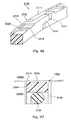
- a convex portion 2212a formed on an outer peripheral surface of an outer peripheral ring 2000 according to a first modification shown in Fig. 36 is formed in such a manner that it extends toward a circumferential direction while changing its position to a high pressure side (H) and a low pressure side (L) in an alternate manner so as to reach positions on opposite side surfaces in a width direction, as in the case of the above-mentioned second practical example.
- the convex portion 2212a is constructed so as to take a rectangular wave shape extending toward a circumferential direction.
- the third concave portions 2221a are each constructed to extend from an end of the high pressure side (H) to a position which does not reach an end of the low pressure side (L) so as to exhibit a function of introducing fluid thereinto from the high pressure side (H) is also the same as in the case of the above-mentioned second practical example.
- the fourth concave portions 2222a are each constructed so as to extend from the end of the low pressure side (L) to a position which does not reach the end of the high pressure side (H) is also the same as in the case of the above-mentioned second practical example.
- bottom surfaces of the third concave portions 2221a and the bottom surfaces of the fourth concave portions 2222a are each composed of a surface which is concentric with the inner peripheral surface of the outer peripheral ring 2000 is also the same as in the case of the above-mentioned second practical example.
- a convex portion 2212b formed on an outer peripheral surface of an outer peripheral ring 2000 according to a second modification shown in Fig. 37 is formed in such a manner that it extends toward a circumferential direction while changing its position to a high pressure side (H) and a low pressure side (L) in an alternate manner so as to reach positions on opposite side surfaces in a width direction, as in the case of the above-mentioned second practical example.
- the convex portion 2212b is constructed so as to take a triangular wave shape extending toward a circumferential direction.
- the following feature is the same as that in the case of the above-mentioned second practical example; that is, due to the formation of such a convex portion 2212b, there are formed on the outer peripheral surface of the outer peripheral ring 2000 a plurality of third concave portions 2221 b which are respectively spaced from one another in the circumferential direction, and a plurality of fourth concave portions 2222b which are respectively spaced from one another in the circumferential direction.
- the third concave portions 2221b are each constructed to extend from an end of the high pressure side (H) to a position which does not reach an end of the low pressure side (L) so as to exhibit a function of introducing fluid thereinto from the high pressure side (H) is also the same as in the case of the above-mentioned second practical example.
- the fourth concave portions 2222b are constructed so as to extend from the end of the low pressure side (L) to a position which does not reach the end of the high pressure side (H) is also the same as in the case of the above-mentioned second practical example.
- bottom surfaces of the third concave portions 2221 b and the bottom surfaces of the fourth concave portions 2222b are each composed of a surface which is concentric with the inner peripheral surface of the outer peripheral ring 2000 is also the same as in the case of the above-mentioned second practical example.
- the outer peripheral rings 2000 can be independently used without the inner peripheral rings 3100, respectively. In this case, a low torque effect can be enhanced.
- a sealing device which is fitted into an annular groove formed in an outer periphery of a shaft so as to seal an annular gap between said shaft and a housing which rotate relative to each other, thereby to hold a fluid pressure in a region to be sealed which is constructed such that the fluid pressure therein changes, is characterized by comprising:
- the convex portions each formed between adjacent concave portions are formed so as to extend from the low pressure side toward the high pressure side as they go in the sliding direction of the outer peripheral ring with respect to the housing. For that reason, the fluid introduced into the concave portions in accordance with the relative rotation between the housing and the outer peripheral ring actively flows from the high pressure side to the low pressure side as well as toward the sliding direction of the housing with respect to the outer peripheral ring.
- the reduction in rigidity of the outer peripheral ring can be suppressed.
- these plurality of convex portions are in a state of contact with the inner peripheral surface of the shaft hole in the housing, so that the outer peripheral ring can be suppressed from being inclined in the annular groove, thereby making it possible to stabilize the mounting state of the outer peripheral ring.
- a sealing device 1000 according to this practical example is composed of an outer peripheral ring 2000 made of resin, and an inner peripheral ring 3100 made of a rubber-like elastic body.
- the inner peripheral ring 3100 according to this practical example is a so-called O ring having a circular cross sectional shape.
- the inner peripheral ring 3100 is not limited to the O ring, but as such there can be adopted other seal ring such as a rectangular or polygonal ring, etc.
- a peripheral length of an outer peripheral surface of the outer peripheral ring 2000 becomes longer than a peripheral length of an inner peripheral surface of a shaft hole in a housing 5000, as explained in the above-mentioned embodiment.
- the peripheral length of the outer peripheral surface thereof is made shorter than the peripheral length of the inner peripheral surface of the shaft hole in the housing 5000, as explained in the above-mentioned embodiment.
- the outer peripheral ring 2000 according to this third practical example of the present invention will be explained in further detail while referring in particular to Fig. 38 through Fig. 40 and Fig. 42 .
- An abutment joint portion 2100 is formed on the outer peripheral ring 2000 at one place in a circumferential direction thereof.
- the outer peripheral ring 2000 is formed on its outer peripheral surface with a plurality of concave portions 2220 which are respectively spaced from one another in the circumferential direction.
- the outer peripheral ring 2000 is constructed such that the abutment joint portion 2100 and the plurality of concave portions 2220 as mentioned above are formed on an annular member of which the cross section is rectangular.
- this is only an explanation of the shape thereof, but does not necessarily mean that an annular member of a rectangular cross section is used as a material, and processing to form the abutment joint portion 2100 and the plurality of concave portions 2220 is applied to this material.
- the abutment joint portion 2100 and the plurality of concave portions 2220 can also be obtained by means of cutting work.
- the plurality of concave portions 2220 may be obtained by means of cutting work. In this manner, the method of production thereof is not limited in particular.
- a special step cut is employed for the abutment joint portion 2100, similar to the above-mentioned embodiment.
- the abutment joint portion 2100 there can be adopted a straight cut, a bias cut, another step cut, and so on, including but not limited to this.
- the outer peripheral ring 2000 may also be endless, without forming the abutment joint portion 2100.
- the concave portions 2220 are formed in plurality in a spaced-apart relation with respect to one another in the circumferential direction.
- the plurality of concave portions 2220 are arranged so as to be at equal intervals, except for the vicinity of the abutment joint portion 2100.
- convex portions 2213 are each formed between adjacent concave portions 2220, respectively, by the formation of the plurality of concave portions 2220.
- the convex portions 2213 are formed so as to extend from a low pressure side (L) toward a high pressure side (H) as they go in the sliding direction of the outer peripheral ring 2000 with respect to the housing 5000.
- the concave portions 2220 are each constructed to extend from an end of the high pressure side (H) to a position which does not reach an end of the low pressure side (L). More specifically, the concave portions 2220 are formed so as to extend to the vicinity of the other end of the outer peripheral ring 2000 at the low pressure side (L).
- the bottom surfaces of the concave portions 2220 are composed of surfaces which are concentric with the inner peripheral surface of the outer peripheral ring 2000.
- the width (width in the axial direction) of the concave portions 2220 the wider the width of the concave portions 2220, the narrower becomes the width of the low pressure side convex portions 2210.
- the narrower this width becomes the more the torque can be reduced, but if the width is made too much narrow, sealing efficiency and durability will become low. Accordingly, it is desirable to narrow the width concerned as much as possible according to service conditions, etc., to such an extent that sealing efficiency and durability can be maintained.
- Fig. 41 shows an unloaded state in which an engine is stopped, and there does not exist a differential pressure (or there exists substantially no differential pressure) between right-hand side region of the sealing device 1000 and left-hand side region of the sealing device 1000.
- Fig. 41 is a schematic cross sectional view (i.e., a cross sectional view including an axis of a shaft 4000) of a portion in which a concave portion 2220 is formed in the outer peripheral ring 2000, wherein the sealing device 1000 in Fig. 41 corresponds to one in an AA cross section in Fig. 38 .
- Fig. 41 shows an unloaded state in which an engine is stopped, and there does not exist a differential pressure (or there exists substantially no differential pressure) between right-hand side region of the sealing device 1000 and left-hand side region of the sealing device 1000.
- Fig. 41 is a schematic cross sectional view (i.e., a cross sectional view including an axis of a shaft 4000) of a portion in which a conca
- FIG. 42 is a partially broken perspective view in the outer peripheral ring 2000, showing the relation between the sliding direction of the outer peripheral ring 2000 with respect to the housing 5000 and the flow of fluid.
- Fig. 43 shows a state in which the engine is operated, and fluid pressure in the right-hand side region of the sealing device 1000 has become higher in comparison with that in the left-hand side region of the sealing device 1000.
- Fig. 43 is a schematic cross sectional view (i.e., a cross sectional view including an axis of a shaft 4000) of a portion in which a concave portion 2220 is formed in the outer peripheral ring 2000, wherein the sealing device 1000 in Fig. 43 corresponds to one in an AA cross section in Fig. 38 .
- the inner peripheral ring 3100 made of a rubber-like elastic body is in intimate contact with the inner peripheral surface of the outer peripheral ring 2000 and a groove bottom surface of the annular groove 4100, respectively. Then, the inner peripheral ring 3100 exhibits a function of pushing the outer peripheral ring 2000 toward its outer peripheral surface side due to the elastic repulsion thereof.
- those portions of the outer peripheral surface of the outer peripheral ring 2000 which exclude the concave portions 2220 i.e., the low pressure side convex portions 2210, the convex portions 2213 and that portion of the outer peripheral ring 2000 in the vicinity of the abutment joint portion 2100 in which a concave portion 2220 is not formed
- the outer peripheral ring 2000 is pushed by means of the fluid pressure from the high pressure side (H), so that it becomes a state of being in intimate contact with the side wall surface of the annular groove 4100 at the low pressure side (L), as shown in Fig. 43 .
- the outer peripheral ring 2000 maintains the state of being in contact (sliding) with the inner peripheral surface of the shaft hole in the housing 5000.
- the inner peripheral ring 3100 too, it also becomes a state of being in intimate contact with the side wall surface of the annular groove 4100 at the low pressure side (L).
- the plurality of convex portions 2213 formed on the outer peripheral surface of the outer peripheral ring 2000 are formed so as to extend from the low pressure side (L) toward the high pressure side (H) as they go in the sliding direction (in the direction of an arrow R in Fig. 42 ) of the outer peripheral ring 2000 with respect to the housing 5000.
- the fluid introduced in the concave portions 2220 actively flows from the high pressure side (H) to the low pressure side (L) as well as toward the sliding direction of the housing 5000 with respect to the outer peripheral ring 2000 (i.e., flows in the direction of an arrow X in Fig. 42 ).
- the reduction in rigidity of the outer peripheral ring 2000 can be suppressed in comparison with the case where the convex portions 2213 are not formed.
- these plurality of convex portions 2213 are in a state of contact with the inner peripheral surface of the shaft hole in the housing 5000, so that the outer peripheral ring 2000 can be suppressed from being inclined in the annular groove 4100, thereby making it possible to stabilize the mounting state of the outer peripheral ring 2000.
- the convex portions 2213 are formed in such a manner that they each extend from the end of the high pressure side (H) to the end of the low pressure side (L) in the outer peripheral ring 2000, it is possible to suppress the tilt or inclination of the outer peripheral ring 2000 in an effective manner.
- the outer peripheral ring 2000 may incline in a counter clockwise direction in these figures.
- the concave portions 2220 are formed over a large area of the outer peripheral surface of the outer peripheral ring 2000. Accordingly, in this practical example, too, it is possible to reduce sliding torque to a sufficient extent, similar to the case of the above-mentioned embodiment.
- the outer peripheral ring 2000 can be independently used without the inner peripheral ring 3100. In this case, a low torque effect can be enhanced.
- a sealing device which is fitted into an annular groove formed in an outer periphery of a shaft so as to seal an annular gap between said shaft and a housing which rotate relative to each other, thereby to hold a fluid pressure in a region to be sealed which is constructed such that the fluid pressure therein changes, is characterized by comprising:
- the convex portions each formed between adjacent concave portions are formed so as to extend from the high pressure side toward the low pressure side as they go in the sliding direction of the outer peripheral ring with respect to the housing.
- the fluid introduced into the concave portions in accordance with the relative rotation between the housing and the outer peripheral ring actively flows from the low pressure side to the high pressure side as well as toward the sliding direction of the housing with respect to the outer peripheral ring.
- the fluid introduced in the concave portions acts in such a manner as to be caused to return to the high pressure side in accordance with relative rotation between the housing and the outer peripheral ring, so it is possible to suppress the leakage of fluid.
- the reduction in rigidity of the outer peripheral ring can be suppressed.
- these plurality of convex portions are in a state of contact with the inner peripheral surface of the shaft hole in the housing, so that the outer peripheral ring can be suppressed from being inclined in the annular groove, thereby making it possible to stabilize the mounting state of the outer peripheral ring.
- a sealing device 1000 according to this practical example is composed of an outer peripheral ring 2000 made of resin, and an inner peripheral ring 3100 made of a rubber-like elastic body.
- the inner peripheral ring 3100 according to this practical example is a so-called O ring having a circular cross sectional shape.
- the inner peripheral ring 3100 is not limited to the O ring, but as such there can be adopted other seal ring such as a rectangular or polygonal ring, etc.
- a peripheral length of an outer peripheral surface of the outer peripheral ring 2000 becomes longer than a peripheral length of an inner peripheral surface of a shaft hole in a housing 5000, as explained in the above-mentioned embodiment.
- the peripheral length of the outer peripheral surface thereof is made shorter than the peripheral length of the inner peripheral surface of the shaft hole in the housing 5000, as explained in the above-mentioned embodiment.
- the outer peripheral ring 2000 according to this fourth practical example of the present invention will be explained in further detail while referring in particular to Fig. 44 through Fig. 46 and Fig. 48 .
- An abutment joint portion 2100 is formed on the outer peripheral ring 2000 at one place in a circumferential direction thereof.
- the outer peripheral ring 2000 is formed on its outer peripheral surface with a plurality of concave portions 2220 which are respectively spaced from one another in a circumferential direction.
- the outer peripheral ring 2000 is constructed such that the abutment joint portion 2100 and the plurality of concave portions 2220 as mentioned above are formed on an annular member of which the cross section is rectangular.
- this is only an explanation of the shape thereof, but does not necessarily mean that an annular member of a rectangular cross section is used as a material, and processing to form the abutment joint portion 2100 and the plurality of concave portions 2220 is applied to this material.
- the abutment joint portion 2100 and the plurality of concave portions 2220 can also be obtained by means of cutting work.
- the plurality of concave portions 2220 may be obtained by means of cutting work. In this manner, the method of production thereof is not limited in particular.
- a special step cut is employed for the abutment joint portion 2100, similar to the above-mentioned embodiment.
- the abutment joint portion 2100 there can be adopted a straight cut, a bias cut, another step cut, and so on, including but not limited to this.
- the outer peripheral ring 2000 may also be endless, without forming the abutment joint portion 2100.
- the concave portions 2220 are formed in plurality in a spaced-apart relation with respect to one another in the circumferential direction.
- the plurality of concave portions 2220 are arranged so as to be at equal intervals, except for the vicinity of the abutment joint portion 2100.
- convex portions 2214 are each formed between adjacent concave portions 2220, respectively, by the formation of the plurality of concave portions 2220.
- the convex portions 2214 are formed so as to extend from a high pressure side (H) toward a low pressure side (L) as they go in the sliding direction of the outer peripheral ring 2000 with respect to the housing 5000.
- the concave portions 2220 are each constructed to extend from an end of the high pressure side (H) to a position which does not reach an end of the low pressure side (L). More specifically, the concave portions 2220 are each formed so as to extend to the vicinity of the other end of the outer peripheral ring 2000 at the low pressure side (L).
- the bottom surfaces of the concave portions 2220 are composed of surfaces which are concentric with the inner peripheral surface of the outer peripheral ring 2000.
- an outer peripheral surface of a portion in which the concave portions 2220 are not formed in the vicinity of the abutment joint portion 2100, and outer peripheral surfaces of the convex portions 2214 and low pressure side convex portions 2210 are composed of the same surface. That is, these peripheral surfaces are concentric with the inner peripheral surface of the outer peripheral ring 2000. Then, a continuous annular surface is formed by the outer peripheral surface of that portion in which the concave portions 2220 are not formed in the vicinity of the abutment joint portion 2100 and the outer peripheral surfaces of the low pressure side convex portions 2210. This continuous annular surface functions as a sealing surface at the outer peripheral surface side in the outer peripheral ring 2000.
- an initial depth of the concave portions 2220 by taking into consideration both the above-mentioned rigidity and the maintenance of introduction of fluid even if the wear progresses with the lapse of time.
- the depth of the concave portions 2220 it is preferable to set the depth of the concave portions 2220 to be equal to or more than about 0.1 mm and equal to or less than about 0.3 mm.
- the width (width in the axial direction) of the concave portions 2220 the wider the width of the concave portions 2220, the narrower becomes the width of the low pressure side convex portions 2210.
- the narrower this width becomes the more the torque can be reduced, but if the width is made too much narrow, sealing efficiency and durability will become low. Accordingly, it is desirable to narrow the width concerned as much as possible according to service conditions, etc., to such an extent that sealing efficiency and durability can be maintained.
- each of the convex portions 2210 is set to be equal to or more than about 0.3 mm and equal to or less than about 0.7 mm.
- the width in the circumferential direction of the convex portions 2214 is equal to or more than 0.3 mm and equal to or less than 0.7 mm.
- Fig. 47 shows an unloaded state in which an engine is stopped, and there does not exist a differential pressure (or there exists substantially no differential pressure) between right-hand side region of the sealing device 1000 and left-hand side region of the sealing device 1000.
- Fig. 47 is a schematic cross sectional view (i.e., a cross sectional view including an axis of a shaft 4000) of a portion in which a concave portion 2220 is formed in the outer peripheral ring 2000, wherein the sealing device 1000 in Fig. 47 corresponds to one in an AA cross section in Fig. 44 .
- Fig. 47 shows an unloaded state in which an engine is stopped, and there does not exist a differential pressure (or there exists substantially no differential pressure) between right-hand side region of the sealing device 1000 and left-hand side region of the sealing device 1000.
- Fig. 47 is a schematic cross sectional view (i.e., a cross sectional view including an axis of a shaft 4000) of a portion in which a conca
- FIG. 48 is a partially broken perspective view in the outer peripheral ring 2000, showing the relation between the sliding direction of the outer peripheral ring 2000 with respect to the housing 5000 and the flow of fluid.
- Fig. 49 shows a state in which the engine is operated, and fluid pressure in the right-hand side region of the sealing device 1000 has become higher in comparison with that in the left-hand side region of the sealing device 1000.
- Fig. 49 is a schematic cross sectional view (i.e., a cross sectional view including an axis of a shaft 4000) of a portion in which a concave portion 2220 is formed in the outer peripheral ring 2000, wherein the sealing device 1000 in Fig. 49 corresponds to one in an AA cross section in Fig. 44 .
- the inner peripheral ring 3100 made of a rubber-like elastic body is in intimate contact with the inner peripheral surface of the outer peripheral ring 2000 and a groove bottom surface of the annular groove 4100, respectively. Then, the inner peripheral ring 3100 exhibits a function of pushing the outer peripheral ring 2000 toward its outer peripheral surface side due to the elastic repulsion thereof.
- those portions of the outer peripheral surface of the outer peripheral ring 2000 which exclude the concave portions 2220 i.e., the low pressure side convex portions 2210, the convex portions 2214 and that portion of the outer peripheral ring 2000 in the vicinity of the abutment joint portion 2100 in which a concave portion 2220 is not formed
- the outer peripheral ring 2000 is pushed by means of the fluid pressure from the high pressure side (H), so that it becomes a state of being in intimate contact with the side wall surface of the annular groove 4100 at the low pressure side (L), as shown in Fig. 49 .
- the outer peripheral ring 2000 maintains the state of being in contact (sliding) with the inner peripheral surface of the shaft hole in the housing 5000.
- the inner peripheral ring 3100 too, it also becomes a state of being in intimate contact with the side wall surface of the annular groove 4100 at the low pressure side (L).
- the plurality of convex portions 2214 formed on the outer peripheral surface of the outer peripheral ring 2000 are formed so as to extend from the high pressure side (H) toward the low pressure side (L) as they go in the sliding direction (in the direction of an arrow R in Fig. 48 ) of the outer peripheral ring 2000 with respect to the housing 5000.
- the fluid introduced in the concave portions 2220 actively flows from the low pressure side (L) to the high pressure side (H) as well as toward the sliding direction of the housing 5000 with respect to the outer peripheral ring 2000 (i.e., flows in the direction of an arrow X in Fig. 48 ).
- the sealing device 1000 and the sealing structure provided with this sealing device according to this practical example, the following advantages are achieved in comparison with the sealing device explained in the above-mentioned embodiment. That is, by means of the convex portions 2214 formed on the outer peripheral ring 2000, the fluid introduced in the concave portions 2220 actively flows toward the direction of the arrow X in Fig. 48 in accordance with relative rotation between the housing 5000 and the outer peripheral ring 2000. Thus, the fluid introduced in the concave portions 2220 acts in such a manner as to be caused to return to the high pressure side (H) in accordance with relative rotation between the housing 5000 and the outer peripheral ring 2000. Accordingly, the leakage of the fluid can be suppressed.
- H high pressure side
- the reduction in rigidity of the outer peripheral ring 2000 can be suppressed in comparison with the case where the convex portions 2214 are not formed.
- these plurality of convex portions 2214 are in a state of contact with the inner peripheral surface of the shaft hole in the housing 5000, so that the outer peripheral ring 2000 can be suppressed from being inclined in the annular groove 4100, thereby making it possible to stabilize the mounting state of the outer peripheral ring 2000.
- the convex portions 2214 are formed in such a manner that they each extend from the end of the high pressure side (H) to the end of the low pressure side (L) in the outer peripheral ring 2000, it is possible to suppress the tilt or inclination of the outer peripheral ring 2000 in an effective manner.
- the outer peripheral ring 2000 may incline in a counter clockwise direction in these figures.
- the concave portions 2220 are formed over a large area of the outer peripheral surface of the outer peripheral ring 2000. Accordingly, in this practical example, too, it is possible to reduce sliding torque to a sufficient extent, similar to the case of the above-mentioned embodiment.
- the outer peripheral ring 2000 can be independently used without the inner peripheral ring 3100. In this case, a low torque effect can be enhanced.
- Fig. 73 for example, on the abutment joint portion 2170, too.
Abstract
an outer peripheral ring made of resin that is in intimate contact with a side wall surface of said annular groove at a low pressure side thereof, and slides with respect to an inner peripheral surface of a shaft hole in said housing through which said shaft is inserted; and
an inner peripheral ring made of a rubber-like elastic body that is in intimate contact with an inner peripheral surface of said outer peripheral ring and a groove bottom surface of said annular groove, respectively, thereby to push said outer peripheral ring toward an outer peripheral surface side thereof;
wherein said outer peripheral ring is formed on its outer peripheral surface with a plurality of concave portions which are spaced from one another in a circumferential direction and which each extend from an end of a high pressure side to a position which does not arrive at an end of a low pressure side, so as to introduce fluid thereinto from the high pressure side; and
wherein convex portions each formed between adjacent concave portions are formed so as to extend from the high pressure side toward the low pressure side as they go in the sliding direction of said outer peripheral ring with respect to said housing.
Description
- The present invention relates to a sealing device and a sealing structure which serve to seal an annular gap between a shaft and a shaft hole in a housing.
- In an automatic transmission (AT) and a continuously variable transmission (CVT) for automotive vehicle, in order to hold oil pressure, there is arranged a seal ring which serves to seal an annular gap between a shaft and a housing which rotate relative to each other. A seal ring according to a conventional example will be explained while referring to Fig. 138 and Fig. 139. Fig. 138 is a schematic cross sectional view showing a state in which oil pressure is not held in the seal ring according to the conventional example. Fig. 139 is a schematic cross sectional view showing a state in which oil pressure is held in the seal ring according to the conventional example. A seal ring 6000 according to the conventional example is fitted in an
annular groove 4100 formed in an outer periphery of ashaft 4000. And, the seal ring 6000 seals an annular gap between a shaft hole in ahousing 5000 and theshaft 4000 by making sliding contact with an inner peripheral surface of the shaft hole in thehousing 5000 through which theshaft 4000 is inserted, and with a side wall surface of theannular groove 4100, respectively. - The seal ring 6000 used for the above-mentioned usage is required to make sliding torque sufficiently low. For that reason, the peripheral length of an outer peripheral surface of the seal ring 6000 is made shorter than the peripheral length of the inner peripheral surface of the shaft hole in the
housing 5000. In this manner, the seal ring 6000 is constructed such that it does not have a tightening margin with respect to the inner peripheral surface of the shaft hole. Then, in a state where an engine of an automotive vehicle is started to operate and the oil pressure is high, the seal ring 6000 is expanded in its diameter due to the oil pressure, so that it makes intimate contact with the inner peripheral surface of the shaft hole and the side wall surface of theannular groove 4100. As a result of this, a function to hold the oil pressure is exhibited to a sufficient extent (refer to Fig. 139). - In contrast to this, in a state where the oil pressure is not applied due to stoppage of the engine, the seal ring 6000 is in a state apart or separated from the inner peripheral surface of the shaft hole or side wall surfaces of the annular groove 4100 (refer to Fig. 138). For that reason, in the state where the oil pressure is not applied, the seal ring 6000 does not exhibit a sealing function. Accordingly, in a construction in which transmission control is carried out by means of oil pressure fed by a hydraulic pump, as in the case of an AT or a CVT, the oil having been sealed by the seal ring 6000 will return to an oil pan in an unloaded condition in which the hydraulic pump is stopped (for example, at the time of idling stop). As a result of this, the oil in the vicinity of the seal ring 6000 will be lost. Thus, when the engine is started (restarted) from this state, there will be no oil in the vicinity of the seal ring 6000, and engine operation will be started in a state where there is no lubrication. For that reason, there is a problem that responsiveness and operability are bad.
-
- [First Patent Document]
Japanese patent No. 4665046 - [Second Patent Document]
Japanese patent application laid-open No. 2011-144847 - [Third Patent Document]
Japanese patent application laid-open No. 2010-265937 - An object of the present invention is to provide a sealing device and a sealing structure which are capable of exhibiting a sealing function even in a state where fluid pressure is low or in a state where there is no fluid pressure, while suppressing sliding torque to a low level.
- In order to solve the above-mentioned problem, the present invention adopts the following means.
- That is, a sealing device of the present invention, which is fitted into an annular groove formed in an outer periphery of a shaft so as to seal an annular gap between said shaft and a housing which rotate relative to each other, thereby to hold a fluid pressure in a region to be sealed which is constructed such that the fluid pressure therein changes, is characterized by comprising:
- an outer peripheral ring made of resin that is in intimate contact with a side wall surface of said annular groove at a low pressure side thereof, and slides with respect to an inner peripheral surface of a shaft hole in said housing through which said shaft is inserted; and
- an inner peripheral ring made of a rubber-like elastic body that is in intimate contact with an inner peripheral surface of said outer peripheral ring and a groove bottom surface of said annular groove, respectively, thereby to push said outer peripheral ring toward an outer peripheral surface side thereof;
- wherein said outer peripheral ring has a concave portion formed on its outer peripheral surface to extend from an end of a high pressure side to a position which does not arrive at an end of a low pressure side, so as to introduce fluid thereinto from the high pressure side.
- Here, note that in the present invention, the "high pressure side" means a side at which pressure is higher than at the other side at the time when a differential pressure has occurred on opposite sides of the sealing device, and the "low pressure side" means a side at which pressure is lower than at the other side at the time when a differential pressure has occurred on opposite sides of the sealing device.
- According to the sealing device of the present invention, the outer peripheral ring is pushed toward the outer peripheral surface side thereof by means of the inner peripheral ring. For that reason, even in a state where the fluid pressure does not act (a differential pressure has not occurred), or in a state where the fluid pressure does not substantially act (a differential pressure has not substantially occurred), the outer peripheral ring will be in a state of being in contact with the inner peripheral surface of the shaft hole in the housing, so that a sealing function thereof can be exhibited. Accordingly, the fluid pressure can be made to be held from immediately after the fluid pressure in the region to be sealed begins to increase. In addition, the concave portion is formed on the outer peripheral surface of the outer peripheral ring, so that fluid can be introduced into this concave portion from the high pressure side. For that reason, even if the fluid pressure becomes higher, the fluid pressure acts toward the inner peripheral surface side of the outer peripheral ring in a region in which the concave portion is formed. Accordingly, an increase in pressure toward the outer peripheral surface by means of the outer peripheral ring accompanying the increase in the fluid pressure can be suppressed, thus making it possible to suppress sliding torque to a low level.
- As described above, according to the present invention, it is possible to exhibit a sealing function even in a state where fluid pressure is low or in a state where there is no fluid pressure, while suppressing sliding torque to a low level.
-
- [
Fig. 1] Fig. 1 is a partially broken cross sectional view of a sealing device according to an embodiment of the present invention. - [
Fig. 2] Fig. 2 is a view of an outer peripheral ring seen from an outer peripheral surface side thereof according to the embodiment of the present invention. - [
Fig. 3] Fig. 3 is a side view of the outer peripheral ring according to the embodiment of the present invention. - [
Fig. 4] Fig. 4 is a partially broken perspective view of the outer peripheral ring according to the embodiment of the present invention. - [
Fig. 5] Fig. 5 is a schematic cross sectional view showing an unloaded state in the sealing device according to the embodiment of the present invention. - [
Fig. 6] Fig. 6 is a schematic cross sectional view showing a high pressure state in the sealing device according to the embodiment of the present invention. - [
Fig. 7] Fig. 7 is a partially broken cross sectional view of a sealing device according to a first reference example of the present invention. - [
Fig. 8] Fig. 8 is a schematic cross sectional view showing an unloaded state in the sealing device according to the first reference example of the present invention. - [
Fig. 9] Fig. 9 is a schematic cross sectional view showing a high pressure state in the sealing device according to the first reference example of the present invention. - [
Fig. 10] Fig. 10 is a partially broken cross sectional view of a sealing device according to a second reference example of the present invention. - [
Fig. 11] Fig. 11 is a partially broken perspective view of an outer peripheral ring according to the second reference example of the present invention. - [
Fig. 12] Fig. 12 is a schematic cross sectional view showing an unloaded state in the sealing device according to the second reference example of the present invention. - [
Fig. 13] Fig. 13 is a schematic cross sectional view showing a high pressure state in the sealing device according to the second reference example of the present invention. - [
Fig. 14] Fig. 14 is a partially broken cross sectional view of a sealing device according to a third reference example of the present invention. - [
Fig. 15] Fig. 15 is a side view of an outer peripheral ring (a side view seen from a low pressure side) according to the third reference example of the present invention. - [
Fig. 16] Fig. 16 is a partially broken perspective view of an outer peripheral ring according to the third reference example of the present invention. - [
Fig. 17] Fig. 17 is a schematic cross sectional view showing an unloaded state in the sealing device according to the third reference example of the present invention. - [
Fig. 18] Fig. 18 is a schematic cross sectional view showing a high pressure state in the sealing device according to the third reference example of the present invention. - [
Fig. 19] Fig. 19 is a partially broken cross sectional view of a sealing device according to a first practical example of the present invention. - [
Fig. 20] Fig. 20 is a view of an outer peripheral ring seen from an outer peripheral surface side thereof according to the first practical example of the present invention. - [
Fig. 21] Fig. 21 is a side view of the outer peripheral ring according to the first practical example of the present invention. - [
Fig. 22] Fig. 22 is a partially broken perspective view of the outer peripheral ring according to the first practical example of the present invention. - [
Fig. 23] Fig. 23 is a schematic cross sectional view showing an unloaded state in the sealing device according to the first practical example of the present invention. - [
Fig. 24] Fig. 24 is a schematic cross sectional view showing an unloaded state in the sealing device according to the first practical example of the present invention. - [
Fig. 25] Fig. 25 is a schematic cross sectional view showing a high pressure state in the sealing device according to the first practical example of the present invention. - [
Fig. 26] Fig. 26 is a part of an external view of an outer peripheral ring according to a first modification of the first practical example of the present invention. - [
Fig. 27] Fig. 27 is a part of an external view of an outer peripheral ring according to a second modification of the first practical example of the present invention. - [
Fig. 28] Fig. 28 is a part of an external view of an outer peripheral ring according to a third modification of the first practical example of the present invention. - [
Fig. 29] Fig. 29 is a partially broken cross sectional view of a sealing device according to a second practical example of the present invention. - [
Fig. 30] Fig. 30 is a part of a view of an outer peripheral ring seen from an outer peripheral surface side thereof according to the second practical example of the present invention. - [
Fig. 31] Fig. 31 is a side view of the outer peripheral ring according to the second practical example of the present invention. - [
Fig. 32] Fig. 32 is a schematic cross sectional view showing an unloaded state in the sealing device according to the second practical example of the present invention. - [
Fig. 33] Fig. 33 is a schematic cross sectional view showing an unloaded state in the sealing device according to the second practical example of the present invention. - [
Fig. 34] Fig. 34 is a schematic cross sectional view showing an unloaded state in the sealing device according to the second practical example of the present invention. - [
Fig. 35] Fig. 35 is a schematic cross sectional view showing a high pressure state in the sealing device according to the second practical example of the present invention. - [
Fig. 36] Fig. 36 is a part of a view of an outer peripheral ring seen from an outer peripheral surface side thereof according to a first modification of the second practical example of the present invention. - [
Fig. 37] Fig. 37 is a part of a view of an outer peripheral ring seen from an outer peripheral surface side thereof according to a second modification of the second practical example of the present invention. - [
Fig. 38] Fig. 38 is a partially broken cross sectional view of a sealing device according to a third practical example of the present invention. - [
Fig. 39] Fig. 39 is a side view of an outer peripheral ring according to the third practical example of the present invention. - [
Fig. 40] Fig. 40 is a partially broken perspective view of the outer peripheral ring according to the third practical example of the present invention. - [
Fig. 41] Fig. 41 is a schematic cross sectional view showing an unloaded state in the sealing device according to the third practical example of the present invention. - [
Fig. 42] Fig. 42 is a partially broken perspective view of the outer peripheral ring according to the third practical example of the present invention. - [
Fig. 43] Fig. 43 is a schematic cross sectional view showing a high pressure state in the sealing device according to the third practical example of the present invention. - [
Fig. 44] Fig. 44 is a partially broken cross sectional view of a sealing device according to a fourth practical example of the present invention. - [
Fig. 45] Fig. 45 is a side view of an outer peripheral ring according to the fourth practical example of the present invention. - [
Fig. 46] Fig. 46 is a partially broken perspective view of the outer peripheral ring according to the fourth practical example of the present invention. - [
Fig. 47] Fig. 47 is a schematic cross sectional view showing an unloaded state in the sealing device according to the fourth practical example of the present invention. - [
Fig. 48] Fig. 48 is a partially broken perspective view of the outer peripheral ring according to the fourth practical example of the present invention. - [
Fig. 49] Fig. 49 is a schematic cross sectional view showing a high pressure state in the sealing device according to the fourth practical example of the present invention. - Hereinafter, modes for carrying out the present invention will be described in detail by way of example based on a preferred embodiment and practical examples thereof with reference to the accompanying drawings. However, the dimensions, materials, shapes, relative arrangements and so on of component parts described in the embodiment and practical examples are not intended to limit the scope of the present invention to these alone in particular as long as there are no specific statements. Here, note that sealing devices according to the present embodiment and practical examples are used for the use or purpose of sealing an annular gap between a shaft and a housing which rotate relative to each other in order to hold oil pressure in speed-change gears or transmissions for automotive vehicles, such as AT, CVT, etc. In addition, in the following description, a "high pressure side" means a side at which pressure is higher than at the other side at the time when a differential pressure has occurred on opposite sides of a sealing device, and a "low pressure side" means a side at which pressure is lower than at the other side at the time when a differential pressure has occurred on the opposite sides of the sealing device.
- Hereinafter, a sealing device and a sealing structure according to an embodiment of the present invention will be explained while referring to
Fig. 1 through Fig. 6 . - The construction of the sealing device and the sealing structure according to the embodiment of the present invention will be explained, while referring in particular to
Fig. 1 ,Fig. 5 andFig. 6 . Thesealing device 1000 according to the present embodiment is mounted or fitted in anannular groove 4100 formed in an outer periphery of ashaft 4000. Then, thesealing device 1000 serves to seal an annular gap between theshaft 4000 and a housing 5000 (an inner peripheral surface of a shaft hole in thehousing 5000 through which theshaft 4000 is inserted) which rotate relative to each other. As a result of this, thesealing device 1000 holds fluid pressure in a region to be sealed which is constructed in such a manner that the fluid pressure (oil or hydraulic pressure in this embodiment) can change. Here, in this embodiment, it is constructed such that fluid pressure in a region at the right side inFig. 5 andFig. 6 can change, and thesealing device 1000 bears the role of holding the fluid pressure in the region to be sealed at the right side in these figures. Here, note that in a state where an engine of an automotive vehicle has been stopped, the fluid pressure in the region to be sealed is low and the engine is in an unloaded state, whereas when the engine is started, the fluid pressure in the region to be sealed will become high. - Then, the
sealing device 1000 according to this embodiment is composed of an outerperipheral ring 2000 made of resin, and an innerperipheral ring 3000 made of a rubber-like elastic body. As preferable examples of a material for the outerperipheral ring 2000, there can be mentioned polyether ether ketone (PEEK), polyphenylene sulfide (PPS), and polytetrafluoroethylene (PTFE). In addition, as preferable examples of a material for the innerperipheral ring 3000, there can be mentioned acrylic rubber (ACM), fluororubber (FKM), and hydrogenated nitrile rubber (HNBR). InFig. 1 ,Fig. 5 andFig. 6 , the innerperipheral ring 3000 is shown in a simplified manner. - In addition, it is constructed such that in a state where the outer
peripheral ring 2000 and the innerperipheral ring 3000 are combined or assembled together, a peripheral length of an outer peripheral surface of the outerperipheral ring 2000 becomes longer than a peripheral length of an inner peripheral surface of the shaft hole in thehousing 5000. Here, note that, for the outerperipheral ring 2000 as a single or separate member, the peripheral length of the outer peripheral surface thereof is made shorter than the peripheral length of the inner peripheral surface of the shaft hole in thehousing 5000. In other words, the outerperipheral ring 2000 as a single member is constructed such that it does not have a tightening margin with respect to the inner peripheral surface of the shaft hole. Accordingly, if the outerperipheral ring 2000 is made in a state where the innerperipheral ring 3000 is not mounted or fitted therein and an external force does not act thereon, the outer peripheral surface of the outerperipheral ring 2000 will not be in contact with the inner peripheral surface of the shaft hole in thehousing 5000. - In particular, the outer
peripheral ring 2000 according to the embodiment of the present invention will be explained in further detail while referring toFig. 1 through Fig. 4 . An abutmentjoint portion 2100 is formed on the outerperipheral ring 2000 at one place in a circumferential direction thereof. In addition, the outerperipheral ring 2000 is formed on its outer peripheral surface with aconcave portion 2220 for introducing fluid. Here, note that the outerperipheral ring 2000 according to this embodiment is constructed such that the abutmentjoint portion 2100 and theconcave portion 2220 as mentioned above are formed on an annular member of which the cross section is rectangular. However, this is only an explanation of the shape thereof, but does not necessarily mean that an annular member of a rectangular cross section is used as a material, and processing to form the abutmentjoint portion 2100 and theconcave portion 2220 is applied to this material. Of course, after an annular member of a rectangular cross section has been molded or formed, the abutmentjoint portion 2100 and theconcave portion 2220 can also be obtained by means of cutting work. However, for example, after molding or forming a member which has the abutmentjoint portion 2100 in advance, theconcave portion 2220 may be obtained by means of cutting work. In this manner, the method of production thereof is not limited in particular. - The abutment
joint portion 2100 adopts a so-called special step cut which is formed by being cut in a stepwise shape even when seen from any of an outer peripheral surface side and opposite side wall surface sides thereof. As a result of this, in the outerperipheral ring 2000, a first fittingconvex portion 2111 and a first fittingconcave portion 2121 are formed at one outer peripheral side of a cut portion, and a second fittingconcave portion 2122 into which the first fittingconvex portion 2111 fits, and a second fittingconvex portion 2112 which fits into the first fittingconcave portion 2121, are formed at the other outer peripheral side. A special step cut has a characteristic of maintaining stable sealing performance even if the peripheral length of the outerperipheral ring 2000 is changed due to thermal expansion and contraction. Such a special step cut is a well-known technique, so a detailed explanation thereof is omitted. - Here, a case of the special step cut has been shown as an example of the abutment
joint portion 2100. However, for the abutmentjoint portion 2100, there can be adopted a straight cut, a bias cut, another step cut, and so on, including but not limited to this. Here, note that the step cut is of a stepwise cut structure even if seen from any of an outer peripheral surface side and an inner peripheral surface side. In addition, in cases where a material (e.g., PTFE, etc.) of low elasticity is adopted as a material of the outerperipheral ring 2000, the outerperipheral ring 2000 may also be endless, without forming the abutmentjoint portion 2100. - The
concave portion 2220 is formed substantially over the entire periphery except for the vicinity of the abutmentjoint portion 2100. In addition, thisconcave portion 2220 is formed in such a manner that it extends from one end (i.e., a high pressure side (H) as referred to later) of the outerperipheral ring 2000 to a location not reaching the other end thereof (i.e., a low pressure side (L) as referred to later). More specifically, thisconcave portion 2220 is formed so as to extend to the vicinity of the other end of the outerperipheral ring 2000. Here, note that a bottom surface of theconcave portion 2220 is composed of a surface which is concentric with an inner peripheral surface of the outerperipheral ring 2000. Hereinafter, a portion of the outer peripheral surface side of the outerperipheral ring 2000 in which theconcave portion 2220 is not formed at the other side (the low pressure side (L)) is referred to as a low pressure sideconvex portion 2210. Here, note that the shallower the depth of theconcave portion 2220, the higher becomes the rigidity of the portion of the outerperipheral ring 2000 in which the low pressure sideconvex portion 2210 is formed. On the other hand, the low pressure sideconvex portion 2210 is worn out due to the relative sliding movement thereof, so the depth of theconcave portion 2220 becomes shallower as the time elapses. For that reason, when the depth of theconcave portion 2220 becomes too much shallow, it will become impossible to introduce fluid therein. Accordingly, it is desirable to set an initial depth of theconcave portion 2220 by taking into consideration both the above-mentioned rigidity and the maintenance of introduction of fluid even if the wear progresses with the lapse of time. For example, in cases where the thickness of the outerperipheral ring 2000 is 1.7 mm, it is preferable to set the depth of theconcave portion 2220 to be equal to or more than about 0.1 mm and equal to or less than about 0.3 mm. - In addition, with respect to the width (width in an axial direction) of the
concave portion 2220, the wider the width of theconcave portion 2220, the narrower becomes the width of the low pressure sideconvex portion 2210. The narrower becomes this width, the more the torque can be reduced, but if the width is made too much narrow, sealing efficiency and durability will become low. Accordingly, it is desirable to narrow the width concerned as much as possible according to service conditions, etc., to such an extent that sealing efficiency and durability can be maintained. Here, note that for example, in cases where the entire length of the width (width in the axial direction) of the outerperipheral ring 2000 is 1.9 mm, it is preferable to set the width of the low pressure sideconvex portion 2210 to be equal to or more than about 0.3 mm and equal to or less than about 0.7 mm. - A mechanism at the time of using the
sealing device 1000 according to this embodiment of the present invention will be explained, while referring in particular toFig. 5 andFig. 6 .Fig. 5 shows an unloaded (or low load) state in which the engine is stopped, and there does not exist a differential pressure (or there exists substantially no differential pressure) between right-hand side region of thesealing device 1000 and left-hand side region of thesealing device 1000.Fig. 6 shows a state in which the engine is operated, and the fluid pressure in the right-hand side region of thesealing device 1000 has become higher in comparison with that in the left-hand side region of thesealing device 1000. - In a state where the
sealing device 1000 is fitted in theannular groove 4100, the innerperipheral ring 3000 made of a rubber-like elastic body is in intimate contact with the inner peripheral surface of the outerperipheral ring 2000 and a groove bottom surface of theannular groove 4100, respectively. Then, the innerperipheral ring 3000 exhibits a function of pushing the outerperipheral ring 2000 toward its outer peripheral surface side due to the elastic repulsion thereof. - Accordingly, even if the engine is in an unloaded state, those portions of the outer peripheral surface of the outer
peripheral ring 2000 which exclude the concave portion 2220 (i.e., the low pressure sideconvex portion 2210 and a portion of the outerperipheral ring 2000 in the vicinity of the abutmentjoint portion 2100 in which theconcave portion 2220 is not formed) maintain a state in which they are in contact with the inner peripheral surface of the shaft hole in thehousing 5000. - Then, in a state in which the engine is started to generate a differential pressure, the outer
peripheral ring 2000 is pushed to the low pressure side (L) by means of the fluid pressure from the high pressure side (H), so that it becomes a state of being in intimate contact with the side wall surface of theannular groove 4100 at the low pressure side (L), as shown inFig. 6 . Here, note that it is needless to say that the outerperipheral ring 2000 maintains the state of being in contact (sliding) with the inner peripheral surface of the shaft hole in thehousing 5000. In addition, with respect to the innerperipheral ring 3000, too, it also becomes a state where it is in intimate contact with the side wall surface of theannular groove 4100 at the low pressure side (L). - According to the
sealing device 1000 and sealing structure provided therewith according to this embodiment of the present invention, the outerperipheral ring 2000 is pushed toward the outer peripheral surface side thereof by mean of the innerperipheral ring 3000. For that reason, even in a state where the fluid pressure does not act (a differential pressure has not occurred), or in a state where the fluid pressure does not substantially act (a differential pressure has not substantially occurred), the outerperipheral ring 2000 becomes the state of being in contact with the inner peripheral surface of the shaft hole in thehousing 5000. Here, note that an annular continuous sealing surface is formed by the outer peripheral surface of the low pressure sideconvex portion 2210 and that portion of the outer peripheral surface of the outerperipheral ring 2000 in which theconcave portion 2220 is not formed in the vicinity of the abutmentjoint portion 2100. - Accordingly, the fluid pressure can be made to be held from immediately after the fluid pressure in the region to be sealed begins to increase. In other words, in an engine having an idling stop function, oil pressure can be made to be held immediately after oil pressure at the side of the region to be sealed begins to increase due to starting of the engine by an accelerator being depressed from an engine stopped state.
- Here, in general, in the case of a seal ring made of resin, the function of suppressing the leakage of fluid is not exhibited so much. However, in this embodiment, the outer
peripheral ring 2000 is pushed toward the outer peripheral surface side thereof by mean of the inner peripheral ring. For that reason, the function of suppressing the leakage of fluid is exhibited to some extent. As a result of this, even after the action of a pump, etc., is stopped due to stoppage of the engine, it becomes possible to maintain the state where a differential pressure has occurred for a while. For that reason, in the engine having an idling stop function, in cases where the stopped state of the engine is not so long, it is possible to maintain the state where a differential pressure has occurred. Accordingly, at the time of carrying out the restarting of the engine, it is possible to hold the fluid pressure in a suitable manner from immediately after that. - In addition, the
concave portion 2220 is formed on the outer peripheral surface of the outerperipheral ring 2000, so that fluid can be introduced into thisconcave portion 2220 from the high pressure side (H). For that reason, even if the fluid pressure becomes higher, the fluid pressure acts toward the inner peripheral surface side of the outerperipheral ring 2000 in a region in which theconcave portion 2220 is formed. Here, in this embodiment, the bottom surface of theconcave portion 2220 is composed of a surface which is concentric with the inner peripheral surface of the outerperipheral ring 2000. For that reason, in the region in which theconcave portion 2220 is formed, a direction in which the fluid pressure acts from the inner peripheral surface side and a direction in which the fluid pressure acts from the outer peripheral surface side become opposite to each other. Furthermore, it is needless to say that in a region in which the outerperipheral ring 2000 receives pressure from both of the inner peripheral surface side and the outer peripheral surface side, an outside diameter of the outerperipheral ring 2000 is larger than an inside diameter thereof, and hence, an area in which the fluid pressure acts becomes wider in the outer peripheral surface side than in the inner peripheral side. Here, note that an arrow inFig. 6 shows how the fluid pressure acts with respect to the outerperipheral ring 2000. In this manner, in thesealing device 1000 according to this embodiment, it is possible to suppress an increase in pressure toward the outer peripheral surface by means of the outerperipheral ring 2000 accompanying an increase in the fluid pressure, thus making it possible to suppress sliding torque to a low level. - Moreover, in this embodiment, the inner
peripheral ring 3000 is in intimate contact with the inner peripheral surface of the outerperipheral ring 2000 and the groove bottom surface of theannular groove 4100, respectively, so that it exhibits a sealing function in these intimate contact portions thereof. For that reason, by the sealing function of the innerperipheral ring 3000, it is possible to suppress the action of the fluid pressure with respect to that portion of the inner peripheral surface of the outerperipheral ring 2000 which corresponds to a sliding portion between the low pressure sideconvex portion 2210 in the outerperipheral ring 2000 and the shaft hole inner peripheral surface. In other words, as shown inFig. 6 , in the region of the low pressure side (L) from the intimate contact portion of the innerperipheral ring 3000, it is possible to suppress the action of the fluid pressure with respect to the inner peripheral surface of the outerperipheral ring 2000. Accordingly, even if the fluid pressure at the high pressure side (H) increases, it is possible to suppress an increase in the pressure to the outer peripheral surface side by the outerperipheral ring 2000 in an effective manner. - Further, in this embodiment, the
concave portion 2220 is formed so as to extend from an end of the high pressure side (H) to the vicinity of an end of the low pressure side (L) and over the entire periphery of the outerperipheral ring 2000 except for the vicinity of the abutmentjoint portion 2100. Thus, in this embodiment, due to the fact that theconcave portion 2220 is formed over a wide range of the outer peripheral surface of the outerperipheral ring 2000, it is possible to make the sliding area between the outerperipheral ring 2000 and the inner peripheral surface of the shaft hole in thehousing 5000 as narrow as possible. As a result, the sliding torque can be reduced very much. Here, note that the sliding area between the outerperipheral ring 2000 and the inner peripheral surface of the shaft hole in thehousing 5000 is sufficiently narrower than the area of intimate contact between the outerperipheral ring 2000 and the side wall surface of theannular groove 4100 at the low pressure side (L). With this, it is possible to suppress the outerperipheral ring 2000 from sliding with respect to the side wall surface of theannular groove 4100 at the low pressure side (L). Accordingly, the outerperipheral ring 2000 according to this embodiment slides at the outer peripheral surface side. For that reason, in comparison with the case of a seal ring which slides with respect to the side wall surface of the annular groove, it becomes easy for a lubricating film (here an oil film) of the fluid being sealed to be formed, so that the sliding torque can be reduced to a further extent. - In this manner, the generation of heat due to sliding can be suppressed by being able to achieve the reduction of the sliding torque. Accordingly, it becomes possible to use the
sealing device 1000 according to this embodiment in a suitable manner even under a high-speed high-pressure environmental condition. - Hereinafter, some more specific examples will be described. Here, note that in the following individual reference examples and individual practical examples, the use of sealing devices, and materials for their outer peripheral rings and inner peripheral rings are as described in the above-mentioned embodiment. Accordingly, in the following individual reference examples and individual practical examples, the explanation of these will be omitted as the case may be.
- Hereinafter, a sealing device and a sealing structure according to a first reference example of the present invention will be explained while referring to
Fig. 7 through Fig. 9 . In this reference example, a construction is shown in which an O ring is adopted as the inner peripheral ring in the above-mentioned embodiment. The other construction and operation of this example are the same as those in the above-mentioned embodiment, and hence, the same parts as those of the above-mentioned embodiment are denoted by the same reference numerals and characters, and the explanation thereof is omitted as the case may be. - A
sealing device 1000 according to this reference example is composed of an outerperipheral ring 2000 made of resin, and an innerperipheral ring 3100 made of a rubber-like elastic body. The innerperipheral ring 3100 according to this reference example is a so-called O ring having a circular cross sectional shape. - It is constructed such that in a state where the outer
peripheral ring 2000 and the innerperipheral ring 3100 are combined or assembled together, a peripheral length of an outer peripheral surface of the outerperipheral ring 2000 becomes longer than a peripheral length of an inner peripheral surface of a shaft hole in ahousing 5000, as explained in the above-mentioned embodiment. Here, note that for the outerperipheral ring 2000 as a single or separate member, the peripheral length of the outer peripheral surface thereof is made shorter than the peripheral length of the inner peripheral surface of the shaft hole in thehousing 5000, as explained in the above-mentioned embodiment. - The outer
peripheral ring 2000 is the same as explained in the above-mentioned embodiment, and so, the detailed explanation thereof is omitted. In addition, a mechanism at the time of use of thesealing device 1000, too, is the same as explained in the above-mentioned embodiment. Here, note thatFig. 8 shows an unloaded state in which an engine is stopped, and there does not exist a differential pressure (or there exists substantially no differential pressure) between right-hand side region of thesealing device 1000 and left-hand side region of thesealing device 1000.Fig. 9 shows a state in which the engine is operated, and fluid pressure in the right-hand side region of thesealing device 1000 has become higher in comparison with that in the left-hand side region of thesealing device 1000. The advantage of thesealing device 1000 and the sealing structure provided with this sealing device according to this reference example are the same as explained in the above-mentioned embodiment. - A sealing device according to a second reference example of the present invention, which is fitted into an annular groove formed in an outer periphery of a shaft so as to seal an annular gap between said shaft and a housing which rotate relative to each other, thereby to hold a fluid pressure in a region to be sealed which is constructed such that the fluid pressure therein changes, is characterized by comprising:
- an outer peripheral ring made of resin that is in intimate contact with a side wall surface of said annular groove at a low pressure side thereof, and slides with respect to an inner peripheral surface of a shaft hole in said housing through which said shaft is inserted; and
- an inner peripheral ring made of a rubber-like elastic body that is fitted in a mounting groove formed in an inner peripheral surface of said outer peripheral ring, and is in intimate contact with a groove bottom surface of said mounting groove and a groove bottom surface of said annular groove, respectively, thereby to push said outer peripheral ring toward an outer peripheral surface side thereof;
- wherein said outer peripheral ring is formed on its outer peripheral surface with a concave portion which extends from an end of a high pressure side to a position which does not arrive at an end of a low pressure side, so as to introduce fluid thereinto from the high pressure side.
- According to the sealing device according to this second reference example, the following advantages are achieved in comparison with the sealing device explained in the above-mentioned embodiment. That is, in this reference example, the inner peripheral ring is fitted into the mounting groove formed in the inner peripheral surface of the outer peripheral ring, so that the position and posture of the inner peripheral ring with respect to the outer peripheral ring are stabilized. Accordingly, the outer peripheral ring can be pushed toward the outer peripheral surface side in a stable manner. In addition, even if fluid pressure acts on the inner and outer peripheral rings, it is possible to suppress the inner peripheral ring from being twisted.
- Hereinafter, a sealing device and a sealing structure according to the second reference example of the present invention will be explained more specifically, while referring to
Fig. 10 through Fig. 13 . Here, note that the basic construction of this example is the same as that of the above-mentioned embodiment and the above-mentioned first reference example, so the same parts are denoted by the same reference numerals and characters, and the explanation thereof is omitted. - A
sealing device 1000 according to this second reference example is composed of an outerperipheral ring 2000 made of resin, and an innerperipheral ring 3100 made of a rubber-like elastic body. The innerperipheral ring 3100 according to this second reference example is a so-called O ring having a circular cross sectional shape. However, the innerperipheral ring 3100 is not limited to the O ring, but as such there can be adopted other seal ring such as a rectangular or polygonal ring, etc. - It is constructed such that in a state where the outer
peripheral ring 2000 and the innerperipheral ring 3100 are combined or assembled together, a peripheral length of an outer peripheral surface of the outerperipheral ring 2000 becomes longer than a peripheral length of an inner peripheral surface of a shaft hole in ahousing 5000, as explained in the above-mentioned embodiment. Here, note that for the outerperipheral ring 2000 as a single or separate member, the peripheral length of the outer peripheral surface thereof is made shorter than the peripheral length of the inner peripheral surface of the shaft hole in thehousing 5000, as explained in the above-mentioned embodiment. - The outer
peripheral ring 2000 according to this second reference example of the present invention will be explained in further detail while referring in particular toFig. 10 and Fig. 11 . An abutmentjoint portion 2100 is formed on the outerperipheral ring 2000 at one place in a circumferential direction thereof. In addition, the outerperipheral ring 2000 is formed on its outer peripheral surface with aconcave portion 2220 for introducing fluid. Further, the outerperipheral ring 2000 is also formed on its inner peripheral surface with a mountinggroove 2321 for mounting the innerperipheral ring 3100 thereon. - Here, note that the outer
peripheral ring 2000 according to this second reference example is constructed such that the abutmentjoint portion 2100, theconcave portion 2220 and the mountinggroove 2321 as mentioned above are formed on an annular member of which the cross section is rectangular. However, this is only an explanation of the shape thereof, but does not necessarily mean that an annular member of a rectangular cross section is used as a material, and processing to form the abutmentjoint portion 2100, theconcave portion 2220 and the mountinggroove 2321 is applied to this material. Of course, after an annular member of a rectangular cross section has been molded or formed, the abutmentjoint portion 2100, theconcave portion 2220 and the mountinggroove 2321 can also be obtained by means of cutting work. However, for example, after molding or forming a member which has the abutmentjoint portion 2100 in advance, theconcave portion 2220 and the mountinggroove 2321 may be obtained by means of cutting work. In this manner, the method of production thereof is not limited in particular. - A special step cut is used for the abutment
joint portion 2100, similar to the above-mentioned embodiment. However, for the abutmentjoint portion 2100, there can be adopted a straight cut, a bias cut, another step cut, and so on, including but not limited to this. In addition, in cases where a material (e.g., PTFE, etc.) of low elasticity is adopted as a material of the outerperipheral ring 2000, the outerperipheral ring 2000 may also be endless, without forming the abutmentjoint portion 2100. - In this second reference example, too, the
concave portion 2220 is formed over the entire periphery of the outerperipheral ring 2000 except for the vicinity of the abutmentjoint portion 2100. Because theconcave portion 2220 is formed as explained in the above-mentioned embodiment, the detailed explanation thereof is omitted. - The mounting
groove 2321 is formed over the entire periphery of the outerperipheral ring 2000 except for the abutmentjoint portion 2100. Here, note that in a state where a gap of a cut portion in the abutmentjoint portion 2100 is lost, the mountinggroove 2321 becomes an annular groove. In addition, with respect to the mountinggroove 2321, a cross sectional shape thereof cut by a plane including an axis (a central axis of a shaft 4000) is a substantially arc shape so as to conform to the shape of the innerperipheral ring 3100. Here, note that in cases where the innerperipheral ring 3100 is not an O ring, that is the innerperipheral ring 3100 does not have a circular cross sectional shape, it is also necessary to conform the cross sectional shape of the mountinggroove 2321 to the cross sectional shape of the inner peripheral ring. - A mechanism at the time of using the
sealing device 1000 according to this second reference example will be explained, while referring in particular toFig. 12 and Fig. 13. Fig. 12 shows an unloaded state in which an engine is stopped, and there does not exist a differential pressure (or there exists substantially no differential pressure) between right-hand side region of thesealing device 1000 and left-hand side region of thesealing device 1000.Fig. 13 shows a state in which the engine is operated, and fluid pressure in the right-hand side region of thesealing device 1000 has become higher in comparison with that in the left-hand side region of thesealing device 1000. - In a state where the
sealing device 1000 is fitted in theannular groove 4100, the innerperipheral ring 3100 made of a rubber-like elastic body is mounted or fitted in the mountinggroove 2321 formed on the inner peripheral surface of the outerperipheral ring 2000. According to this, the innerperipheral ring 3100 is in intimate contact with the groove bottom surface of the mountinggroove 2321 in the outerperipheral ring 2000 and the groove bottom surface of theannular groove 4100, respectively. Then, the innerperipheral ring 3100 exhibits a function of pushing the outerperipheral ring 2000 toward its outer peripheral surface side due to the elastic repulsion thereof. - Accordingly, even if the engine is in an unloaded state, those portions of the outer peripheral surface of the outer
peripheral ring 2000 which exclude the concave portion 2220 (i.e., the low pressure sideconvex portion 2210 and a portion of the outerperipheral ring 2000 in the vicinity of the abutmentjoint portion 2100 in which theconcave portion 2220 is not formed) maintain a state in which they are in contact with the inner peripheral surface of the shaft hole in thehousing 5000. - Then, in a state in which the engine is started to generate a differential pressure, the outer
peripheral ring 2000 is pushed to the low pressure side (L) by means of the fluid pressure from the high pressure side (H), so that it becomes a state of being in intimate contact with the side wall surface of theannular groove 4100 at the low pressure side (L), as shown inFig. 13 . Here, note that it is needless to say that the outerperipheral ring 2000 maintains the state of being in contact (sliding) with the inner peripheral surface of the shaft hole in thehousing 5000. And, with respect to the innerperipheral ring 3100, it is fitted in the mountinggroove 2321 in the outerperipheral ring 2000, so the position and posture of the innerperipheral ring 3100 with respect to the outerperipheral ring 2000 are maintained in a stable state. - According to the
sealing device 1000 and the sealing structure provided with this sealing device according to this second reference example, the following advantages are achieved in comparison with the sealing device explained in the above-mentioned embodiment. That is, the innerperipheral ring 3100 is mounted or fitted in the mountinggroove 2321 formed in the inner peripheral surface of the outerperipheral ring 2000, so that the position and posture of the innerperipheral ring 3100 with respect to the outerperipheral ring 2000 are stabilized. Accordingly, the outerperipheral ring 2000 can be pushed toward the outer peripheral surface side thereof in a stable manner. In addition, even if fluid pressure acts on the outer peripheral ring 2000 (i.e., fluid pressure varies), it is possible to suppress the innerperipheral ring 3100 from being twisted. - A sealing device according to a third reference example of the present invention, which is fitted into an annular groove formed in an outer periphery of a shaft so as to seal an annular gap between said shaft and a housing which rotate relative to each other, thereby to hold a fluid pressure in a region to be sealed which is constructed such that the fluid pressure therein changes, is characterized by comprising:
- an outer peripheral ring made of resin that makes intimate contact with a side wall surface at a low pressure side in said in an annular groove and carries out sliding movement with respect to an inner peripheral surface of a shaft hole in said housing through which said shaft is inserted; and
- an inner peripheral ring made of a rubber-like elastic body that makes intimate contact with the inner peripheral surface of said of the outer peripheral ring and a groove bottom surface of said annular groove, respectively, thereby to push said outer peripheral ring toward an outer peripheral surface side;
- wherein said outer peripheral ring is formed on its outer peripheral surface with a first concave portion which extends from an end of a high pressure side to a position which does not arrive at an end of a low pressure side, so as to introduce fluid thereinto from the high pressure side; and
- wherein said outer peripheral ring is formed on its inner peripheral surface with a second concave portion in which said inner peripheral ring is fitted and which extends from an end of a low pressure side to a position which does not arrive at an end of a high pressure side, so as to limit a range of movement in an axial direction of said inner peripheral ring.
- According to the sealing device according to this third reference example, the following advantages are achieved in comparison with the sealing device explained in the above-mentioned embodiment. That is, in this reference example, the inner peripheral ring is mounted or fitted in the second concave portion formed on the inner peripheral surface of the outer peripheral ring, so that the range of movement thereof in the axial direction is limited. For that reason, the position and posture of the inner peripheral ring with respect to the outer peripheral ring are stabilized. Accordingly, the outer peripheral ring can be pushed toward the outer peripheral surface side thereof in a stable manner. In addition, even if fluid pressure acts on the outer peripheral ring, it is possible to suppress the inner peripheral ring from being twisted.
- Hereinafter, a sealing device and a sealing structure according to the third reference example of the present invention will be explained more specifically while referring to
Fig. 14 through Fig. 18 . Here, note that the basic construction of this example is the same as that of the above-mentioned embodiment and individual reference examples, and hence, the same component parts are denoted by the same reference numerals and characters, and the explanation thereof is omitted as the case may be. - A
sealing device 1000 according to this third reference example is composed of an outerperipheral ring 2000 made of resin, and an innerperipheral ring 3100 made of a rubber-like elastic body. The innerperipheral ring 3100 according to this third reference example is a so-called O ring having a circular cross sectional shape. However, the innerperipheral ring 3100 is not limited to the O ring, but as such there can be adopted other seal ring such as a rectangular or polygonal ring, etc. - It is constructed such that in a state where the outer
peripheral ring 2000 and the innerperipheral ring 3100 are combined or assembled together, a peripheral length of an outer peripheral surface of the outerperipheral ring 2000 becomes longer than a peripheral length of an inner peripheral surface of a shaft hole in ahousing 5000, as explained in the above-mentioned embodiment. Here, note that for the outerperipheral ring 2000 as a single or separate member, the peripheral length of the outer peripheral surface thereof is made shorter than the peripheral length of the inner peripheral surface of the shaft hole in thehousing 5000, as explained in the above-mentioned embodiment. - The outer
peripheral ring 2000 according to this third reference example of the present invention will be explained in further detail while referring in particular toFig. 14 through Fig. 16 . An abutmentjoint portion 2100 is formed on the outerperipheral ring 2000 at one place in a circumferential direction thereof. In addition, the outerperipheral ring 2000 is formed on its outer peripheral surface with a firstconcave portion 2220 for introducing fluid. Further, the outerperipheral ring 2000 is formed on its inner peripheral surface with a secondconcave portion 2322 in which the innerperipheral ring 3100 is fitted. - Here, note that the outer
peripheral ring 2000 according to this third reference example is constructed such that the abutmentjoint portion 2100, the firstconcave portion 2220 and the secondconcave portion 2322 as mentioned above are formed on an annular member of which the cross section is rectangular. However, this is only an explanation of the shape thereof, but does not necessarily mean that an annular member of a rectangular cross section is used as a material, and processing to form the abutmentjoint portion 2100, the firstconcave portion 2220 and the secondconcave portion 2322 is applied to this material. Of course, after an annular member of a rectangular cross section has been molded or formed, the abutmentjoint portion 2100, the firstconcave portion 2220 and the secondconcave portion 2322 can also be obtained by means of cutting work. However, for example, after molding or forming a member which has the abutmentjoint portion 2100 in advance, the firstconcave portion 2220 and the secondconcave portion 2322 may be obtained by means of cutting work. In this manner, the method of production thereof is not limited in particular. - A special step cut is employed for the abutment
joint portion 2100, similar to the above-mentioned embodiment. However, for the abutmentjoint portion 2100, there can be adopted a straight cut, a bias cut, another step cut, and so on, including but not limited to this. In addition, in cases where a material (e.g., PTFE, etc.) of low elasticity is adopted as a material of the outerperipheral ring 2000, the outerperipheral ring 2000 may also be endless, without forming the abutmentjoint portion 2100. - In this third reference example, too, the first
concave portion 2220 is formed over the entire periphery of the outerperipheral ring 2000 except for the vicinity of the abutmentjoint portion 2100. With respect to the firstconcave portion 2220, it is the same as explained in the above-mentioned embodiment (i.e., the same construction as theconcave portion 2220 in the above-mentioned embodiment), so the detailed explanation thereof is omitted. - Also, the second
concave portion 2322 is formed over the entire periphery of the outerperipheral ring 2000 except for the abutmentjoint portion 2100. Here, note that in a state where a gap of a cut portion in the abutmentjoint portion 2100 is lost, the secondconcave portion 2322 becomes an annular concave portion. However, in cases where to form a concave portion in the vicinity of the abutmentjoint portion 2100 is difficult, it is not necessary to form the concave portion in the vicinity of the abutmentjoint portion 2100. This secondconcave portion 2322 is formed in such a manner that it extends from one end (i.e., a low pressure side (L)) of the outerperipheral ring 2000 to a location not reaching the other end thereof (i.e., a high pressure side (H)). Here, in the inner peripheral surface side of the outerperipheral ring 2000, an annular convex portion (substantially annular convex portion) 2311, which remains in the vicinity of the other end thereof without the secondconcave portion 2322 being formed, functions as a stopper which serves to restrict the axial movement of the innerperipheral ring 3100. - A mechanism at the time of using the
sealing device 1000 according to this third reference example will be explained, while referring in particular toFig. 17 and Fig. 18. Fig. 17 shows an unloaded state in which an engine is stopped, and there does not exist a differential pressure (or there exists substantially no differential pressure) between right-hand side region of thesealing device 1000 and left-hand side region of thesealing device 1000.Fig. 18 shows a state in which the engine is operated, and fluid pressure in the right-hand side region of thesealing device 1000 has become higher in comparison with that in the left-hand side region of thesealing device 1000. - In a state where the
sealing device 1000 is fitted in theannular groove 4100, the innerperipheral ring 3100 made of a rubber-like elastic body is mounted or fitted in the secondconcave portion 2322 formed on the inner peripheral surface of the outerperipheral ring 2000. According to this, the innerperipheral ring 3100 is in intimate contact with the inner peripheral surface of the outer peripheral ring 2000 (i.e., the inner peripheral surface of that portion in which the secondconcave portion 2322 is formed) and the the groove bottom surface of theannular groove 4100, respectively. Then, the innerperipheral ring 3100 exhibits a function of pushing the outerperipheral ring 2000 toward its outer peripheral surface side due to the elastic repulsion thereof. - Accordingly, even if the engine is in an unloaded state, those portions of the outer peripheral surface of the outer
peripheral ring 2000 which exclude the first concave portion 2220 (i.e., the low pressure sideconvex portion 2210 and a portion of the outerperipheral ring 2000 in the vicinity of the abutmentjoint portion 2100 in which the firstconcave portion 2220 is not formed) maintain a state in which they are in contact with the inner peripheral surface of the shaft hole in thehousing 5000. - Then, in a state in which the engine is started to generate a differential pressure, the outer
peripheral ring 2000 is pushed by means of the fluid pressure from the high pressure side (H), so that it becomes a state of being in intimate contact with the side wall surface of theannular groove 4100 at the low pressure side (L), as shown inFig. 18 . Here, note that it is needless to say that the outerperipheral ring 2000 maintains the state of being in contact (sliding) with the inner peripheral surface of the shaft hole in thehousing 5000. - In addition, with respect to the inner
peripheral ring 3100, it is fitted in the secondconcave portion 2322 in the outerperipheral ring 2000, so that a movement thereof in the axial direction is limited. In other words, the movement of the innerperipheral ring 3100 toward the high pressure side (H) is limited by theconvex portion 2311 formed at the inner peripheral surface side of the outerperipheral ring 2000. As a result, the position and posture of the innerperipheral ring 3100 with respect to the outerperipheral ring 2000 are kept in a stable state. - According to the
sealing device 1000 and the sealing structure provided with this sealing device according to this third reference example, the following advantages are achieved in comparison with the sealing device explained in the above-mentioned embodiment. That is, the innerperipheral ring 3100 is mounted or fitted in the secondconcave portion 2322 formed on the inner peripheral surface of the outerperipheral ring 2000, so that the range of movement thereof in the axial direction is limited. As a result, the position and posture of the innerperipheral ring 3100 with respect to the outerperipheral ring 2000 are stabilized. Accordingly, the outerperipheral ring 2000 can be pushed toward the outer peripheral surface side thereof in a stable manner. In addition, even if fluid pressure acts on the outer peripheral ring 2000 (i.e., fluid pressure varies), it is possible to suppress the innerperipheral ring 3100 from being twisted. - A sealing device according to a first practical example of the present invention, which is fitted into an annular groove formed in an outer periphery of a shaft so as to seal an annular gap between said shaft and a housing which rotate relative to each other, thereby to hold a fluid pressure in a region to be sealed which is constructed such that the fluid pressure therein changes, is characterized by comprising:
- an outer peripheral ring made of resin that makes intimate contact with a side wall surface at a low pressure side in said in an annular groove and carries out sliding movement with respect to an inner peripheral surface of a shaft hole in said housing through which said shaft is inserted; and
- an inner peripheral ring made of a rubber-like elastic body that makes intimate contact with the inner peripheral surface of said of the outer peripheral ring and a groove bottom surface of said annular groove, respectively, thereby to push said outer peripheral ring toward an outer peripheral surface side;
- wherein said outer peripheral ring is formed on its outer peripheral surface with a plurality of concave portions which are spaced with respect to one another in a circumferential direction and which each extend from an end of a high pressure side to a position which does not arrive at an end of a low pressure side, so as to introduce fluid thereinto from the high pressure side.
- According to the sealing device according to this practical example, the following advantages are achieved in comparison with the sealing device explained in the above-mentioned embodiment. That is, in this practical example, the concave portions are formed in plurality in a spaced-apart relation with respect to one another in a circumferential direction. For that reason, the portions between adjacent concave portions will be in a state of contact with the inner peripheral surface of the shaft hole in the housing, and can suppress the reduction in rigidity of the outer peripheral ring. Accordingly, it is possible to suppress the outer peripheral ring from being inclined in the annular groove, thereby making it possible to stabilize the mounting state of the outer peripheral ring.
- Hereinafter, a sealing device and a sealing structure according to the first practical example of the present invention will be explained more specifically while referring to
Fig. 19 through Fig. 28 . Here, note that the basic construction of this example is the same as that of the above-mentioned embodiment and individual reference examples, and hence, the same component parts are denoted by the same reference numerals and characters, and the explanation thereof is omitted as the case may be. - A
sealing device 1000 according to this practical example is composed of an outerperipheral ring 2000 made of resin, and an innerperipheral ring 3100 made of a rubber-like elastic body. The innerperipheral ring 3100 according to this practical example is a so-called O ring having a circular cross sectional shape. However, the innerperipheral ring 3100 is not limited to the O ring, but as such there can be adopted other seal ring such as a rectangular or polygonal ring, etc. - It is constructed such that in a state where the outer
peripheral ring 2000 and the innerperipheral ring 3100 are combined or assembled together, a peripheral length of an outer peripheral surface of the outerperipheral ring 2000 becomes longer than a peripheral length of an inner peripheral surface of a shaft hole in ahousing 5000, as explained in the above-mentioned embodiment. Here, note that for the outerperipheral ring 2000 as a single or separate member, the peripheral length of the outer peripheral surface thereof is made shorter than the peripheral length of the inner peripheral surface of the shaft hole in thehousing 5000, as explained in the above-mentioned embodiment. - The outer
peripheral ring 2000 according to this practical example of the present invention will be explained in further detail while referring in particular toFig. 19 through Fig. 22 . An abutmentjoint portion 2100 is formed on the outerperipheral ring 2000 at one place in a circumferential direction thereof. In addition, the outerperipheral ring 2000 is formed on its outer peripheral surface with a plurality ofconcave portions 2220 which are respectively spaced from one another in a circumferential direction. - Here, note that the outer
peripheral ring 2000 according to this practical example is constructed such that the abutmentjoint portion 2100 and the plurality ofconcave portions 2220 as mentioned above are formed on an annular member of which the cross section is rectangular. However, this is only an explanation of the shape thereof, but does not necessarily mean that an annular member of a rectangular cross section is used as a material, and processing to form the abutmentjoint portion 2100 and the plurality ofconcave portions 2220 is applied to this material. Of course, after an annular member of a rectangular cross section has been molded or formed, the abutmentjoint portion 2100 and the plurality ofconcave portions 2220 can also be obtained by means of cutting work. However, for example, after molding or forming a member which has the abutmentjoint portion 2100 in advance, the plurality ofconcave portions 2220 may be obtained by means of cutting work. In this manner, the method of production thereof is not limited in particular. - A special step cut is employed for the abutment
joint portion 2100, similar to the above-mentioned embodiment. However, for the abutmentjoint portion 2100, there can be adopted a straight cut, a bias cut, another step cut, and so on, including but not limited to this. In addition, in cases where a material (e.g., PTFE, etc.) of low elasticity is adopted as a material of the outerperipheral ring 2000, the outerperipheral ring 2000 may also be endless, without forming the abutmentjoint portion 2100. - That is, in this practical example, the
concave portions 2220 are formed in plurality in a spaced-apart relation with respect to one another in a circumferential direction. Here, note that in this practical example, the plurality ofconcave portions 2220 are arranged so as to be at equal intervals, except for the vicinity of the abutmentjoint portion 2100. In addition, theconcave portions 2220 are constructed in such a manner that they each have a relatively long length in the circumferential direction, and the length in the circumferential direction of each portion between the adjacentconcave portions 2220 except for the vicinity of the abutmentjoint portion 2100 becomes shorter in comparison with the length in the circumferential direction of each of the adjacentconcave portions 2220. Hereinafter, the portions between the adjacentconcave portions 2220 are each called arib 2211. With such a construction, theconcave portions 2220 are formed over substantially the entire region in the circumferential direction. In other words, except for those portions in which the abutmentjoint portion 2100 and the plurality ofribs 2211 each having a short length in the circumferential direction are formed, theconcave portions 2220 are formed over the entire region of the outerperipheral ring 2000 in the circumferential direction. In addition, it is constructed such that the opposite side surfaces of eachrib 2211 in this practical example are vertical from the bottom surfaces of the adjacentconcave portions 2220. - In addition, the
concave portions 2220 are formed in such a manner that they each extend from one end of the outerperipheral ring 2000 to a location not reaching the other end thereof, similar to the case of the above-mentioned embodiment. More specifically, theconcave portions 2220 are formed so as to extend to the vicinity of the other end of the outerperipheral ring 2000. Here, note that in this practical example, too, the bottom surfaces of theconcave portions 2220 are composed of surfaces which are concentric with the inner peripheral surface of the outerperipheral ring 2000. The shallower the depth of theconcave portions 2220, the higher becomes the rigidity of those portions of the outerperipheral ring 2000 in which theribs 2211 and low pressure sideconvex portions 2210 are formed. On the other hand, theseribs 2211 and low pressure sideconvex portions 2210 are worn out due to the relative sliding movement thereof, so the depth of theconcave portions 2220 becomes shallower as the time elapses. For that reason, when the depth of theconcave portions 2220 becomes too much shallow, it will become impossible to introduce fluid therein. Accordingly, it is desirable to set an initial depth of theconcave portions 2220 by taking into consideration both the above-mentioned rigidity and the maintenance of introduction of fluid even if the wear progresses with the lapse of time. For example, in cases where the thickness of the outerperipheral ring 2000 is 1.7 mm, it is preferable to set the depth of theconcave portions 2220 to be equal to or more than about 0.1 mm and equal to or less than about 0.3 mm. - Moreover, with respect to the width (width in the axial direction) of the
concave portions 2220, the wider the width of theconcave portions 2220, the narrower becomes the width of the low pressure sideconvex portions 2210. The narrower this width becomes, the more the torque can be reduced, but if the width is made too much narrow, sealing efficiency and durability will become low. Accordingly, it is desirable to narrow the width concerned as much as possible according to service conditions, etc., to such an extent that sealing efficiency and durability can be maintained. Here, note that for example, in cases where the entire length of the width (width in the axial direction) of the outerperipheral ring 2000 is 1.9 mm, it is preferable to set the width of the low pressure sideconvex portions 2210 to be equal to or more than about 0.3 mm and equal to or less than about 0.7 mm. Also, it is preferable to set the width in the circumferential direction of theribs 2211 to be equal to or more than 0.3 mm and equal to or less than 0.7 mm. - A mechanism at the time of using the
sealing device 1000 according to this practical example will be explained, while referring in particular toFig. 23 through Fig. 25 .Fig. 23 andFig. 24 each show an unloaded state in which an engine is stopped, and there does not exist a differential pressure (or there exists substantially no differential pressure) between right-hand side region of thesealing device 1000 and left-hand side region of thesealing device 1000. Here, note thatFig. 23 is a schematic cross sectional view (i.e., a cross sectional view including an axis of a shaft 4000) of a portion in which aconcave portion 2220 is formed in the outerperipheral ring 2000, andFig. 24 is a schematic cross sectional view (i.e., a cross sectional view including the axis of the shaft 4000) of a portion in which arib 2211 is formed in the outerperipheral ring 2000. The outerperipheral ring 2000 inFig. 23 corresponds to an AA cross section inFig. 21 , and the outerperipheral ring 2000 inFig. 24 corresponds to a BB cross section inFig. 21 .Fig. 25 shows a state in which the engine is operated, and fluid pressure in the right-hand side region of thesealing device 1000 has become higher in comparison with that in the left-hand side region of thesealing device 1000. Here, note thatFig. 25 is a schematic cross sectional view (i.e., a cross sectional view including the axis of the shaft 4000) of a portion in which aconcave portion 2220 is formed in the outerperipheral ring 2000. The outerperipheral ring 2000 inFig. 25 corresponds to the AA cross section inFig. 21 . - In a state where the
sealing device 1000 is fitted in anannular groove 4100, the innerperipheral ring 3100 made of a rubber-like elastic body is in intimate contact with the inner peripheral surface of the outerperipheral ring 2000 and a groove bottom surface of theannular groove 4100, respectively. Then, the innerperipheral ring 3100 exhibits a function of pushing the outerperipheral ring 2000 toward its outer peripheral surface side due to the elastic repulsion thereof. - Accordingly, even if the engine is in an unloaded state, those portions of the outer peripheral surface of the outer
peripheral ring 2000 which exclude the concave portions 2220 (i.e., the low pressure sideconvex portions 2210, theribs 2211 and a portion of the outerperipheral ring 2000 in the vicinity of the abutmentjoint portion 2100 in which aconcave portion 2220 is not formed) maintain a state in which they are in contact with the inner peripheral surface of the shaft hole in thehousing 5000. - Then, in a state in which the engine is started to generate a differential pressure, the outer
peripheral ring 2000 is pushed by means of the fluid pressure from the high pressure side (H), so that it becomes a state of being in intimate contact with the side wall surface of theannular groove 4100 at the low pressure side (L), as shown inFig. 25 . Here, note that it is needless to say that the outerperipheral ring 2000 maintains the state of being in contact (sliding) with the inner peripheral surface of the shaft hole in thehousing 5000. In addition, with respect to the innerperipheral ring 3100, too, it also becomes a state of being in intimate contact with the side wall surface of theannular groove 4100 at the low pressure side (L). - According to the
sealing device 1000 and the sealing structure provided with this sealing device according to this practical example, the following advantages are achieved in comparison with the sealing device and the sealing structure explained in the above-mentioned embodiment. That is, theconcave portions 2220 are formed in plurality in a spaced-apart relation in a circumferential direction with respect to one another, and hence, the portions (ribs 2211) between adjacentconcave portions 2220 will be in a state of contact with the inner peripheral surface of the shaft hole in thehousing 5000. In addition, because of the provision of the plurality ofribs 2211, the reduction in rigidity of the outerperipheral ring 2000 can be suppressed in comparison with the case where theribs 2211 are not formed. Accordingly, it is possible to suppress the outerperipheral ring 2000 from being inclined in theannular groove 4100, thereby making it possible to stabilize the mounting state of the outerperipheral ring 2000. Here, note that in cases where a construction is adopted in which the plurality ofribs 2211 are not formed, there will be a fear that inFig. 23 andFig. 25 , the outerperipheral ring 2000 may incline in a counter clockwise direction in these figures. - In addition, in the outer
peripheral ring 2000 according to this practical example, the plurality ofribs 2211 are formed, but theseribs 2211 are constructed in such a manner that the length thereof in the circumferential direction becomes short. For that reason, in this practical example, too, theconcave portions 2220 are formed over a large area of the outer peripheral surface of the outerperipheral ring 2000. Accordingly, in this practical example, too, it is possible to reduce sliding torque to a sufficient extent, similar to the case of the above-mentioned embodiment. - Sealing devices according to modifications of the first practical example of the present invention will be explained while referring to
Fig. 26 through Fig. 28 . In the first practical example, there has been shown the case where the opposite side surfaces of each rib are constructed to be vertical from the bottom surfaces of adjacent concave portions. In contrast to this, in each of the following modifications, there is shown a construction in which a bottom surface of each concave portion and an outer peripheral surface of each rib in an outer peripheral ring are connected with each other through an inclined surface. The other construction in these modifications is the same as that in the above-mentioned first practical example, so the explanation thereof is omitted. - In these modifications, only the shapes of the concave portions and the ribs of the outer peripheral ring are different from those in the first practical example. That is, in these modifications, a bottom surface of each concave portion and an outer peripheral surface of each rib are connected with each other through an inclined surface. Hereinafter, this will be described in more detail with reference to
Fig. 26 through Fig. 28 . Here, note thatFig. 26 through Fig. 28 show examples in which the shapes of inclined surfaces are respectively different from one another. In addition, in these individual figures, (a) is a part of a perspective view of the outer peripheral ring, and (b) is a part of a side elevational view of the outer peripheral ring. Moreover, in the individual figures, for the sake of convenience, although an outer peripheral portion, an inner peripheral portion, and a bottom surface of a concave portion are drawn linearly, they are circular arc in practice. - In a first modification shown in
Fig. 26 , a bottom surface of aconcave portion 2220a and an outer peripheral surface of eachrib 2211 a in an outerperipheral ring 2000 are connected with each other through an inwardly concaved curved surface (a curved inclined surface) 2211a1. - In a second modification shown in
Fig. 27 , a bottom surface of aconcave portion 2220b and an outer peripheral surface of eachrib 2211 b in an outerperipheral ring 2000 are connected with each other through a curved surface (a curved inclined surface) 2211b1 which is bulged outwardly at an outer peripheral surface side thereof, and is concaved inwardly at an inner peripheral surface side thereof. - In a third modification shown in
Fig. 28 , a bottom surface of aconcave portion 2220c and an outer peripheral surface of eachrib 2211c in an outerperipheral ring 2000 are connected with each other through a planar inclined surface 2211c1. - In the sealing devices (the outer peripheral rings 2000) according to the various kinds of modifications constructed as described above, too, the same effects as in the above-mentioned first practical example can be obtained. In addition, in the case of each of the outer
peripheral rings 2000 according to the various kinds of modifications, it is constructed such that a bottom surface of each concave portion and an outer peripheral surface of each rib are connected with each other through an inclined surface. Accordingly, the strength of each rib can be enhanced as compared with the case of the first practical example, keeping the sliding area thereof with respect to an inner peripheral surface of a shaft hole in a housing to the same extent as in the above-mentioned first practical example. As a result, the reduction in rigidity of each of the outer peripheral rings can be suppressed to a further extent. - Here, note that in the first practical example and the various kinds of modifications of the first practical example, in cases where a sealing function does not need to be exhibited in a state where fluid pressure is low or in a state where there is no fluid pressure, the outer
peripheral rings 2000 can be independently used without the innerperipheral rings 3100, respectively. In this case, a low torque effect can be enhanced. - A sealing device according to a second practical example of the present invention, which is fitted into an annular groove formed in an outer periphery of a shaft so as to seal an annular gap between said shaft and a housing which rotate relative to each other, thereby to hold a fluid pressure in a region to be sealed which is constructed such that the fluid pressure therein changes, is characterized by comprising:
- an outer peripheral ring made of resin that is in intimate contact with a side wall surface of said annular groove at a low pressure side thereof, and slides with respect to an inner peripheral surface of a shaft hole in said housing through which said shaft is inserted; and
- an inner peripheral ring made of a rubber-like elastic body that is in intimate contact with an inner peripheral surface of said outer peripheral ring and a groove bottom surface of said annular groove, respectively, thereby to push said outer peripheral ring toward an outer peripheral surface side thereof;
- wherein a portion in said outer peripheral ring which slides with respect to the inner peripheral surface of said shaft hole is constructed by a convex portion which is formed so as to extend toward a circumferential direction while changing its position to a high pressure side and a low pressure side in an alternate manner.
- According to the sealing device according to this practical example, the following advantages are achieved in comparison with the sealing device explained in the above-mentioned embodiment. That is, in this practical example, the convex portion formed on an outer peripheral surface of the outer peripheral ring is formed so as to extend toward a circumferential direction while changing its position to a high pressure side and a low pressure side in an alternate manner. Accordingly, it is possible to suppress the outer peripheral ring from being inclined in the annular groove, thereby making it possible to stabilize the mounting state of the outer peripheral ring. Here, note that in this practical example, the convex portion formed so as to extend toward a circumferential direction while changing its position to a high pressure side and a low pressure side in an alternate manner is formed on the outer peripheral surface of the outer peripheral ring. For that reason, in a state where the sealing device is fitted, the concave portion opened to the high pressure side exists in plurality on the outer peripheral surface side of the outer peripheral ring. Then, fluid is introduced into these plurality of concave portions from the high pressure side. Accordingly, these plurality of concave portions exhibit the same function as the
concave portion 2220 in the above-mentioned embodiment. - Hereinafter, a sealing device and a sealing structure according to the second practical example of the present invention will be explained more specifically while referring to
Fig. 29 through Fig. 37 . Here, note that the basic construction of this example is the same as that of the above-mentioned embodiment, individual reference examples and first practical example, and hence, the same parts are denoted by the same reference numerals and characters, and the explanation thereof is omitted as the case may be. - A
sealing device 1000 according to this practical example is composed of an outerperipheral ring 2000 made of resin, and an innerperipheral ring 3100 made of a rubber-like elastic body. The innerperipheral ring 3100 according to this practical example is a so-called O ring having a circular cross sectional shape. However, the innerperipheral ring 3100 is not limited to the O ring, but as such there can be adopted other seal ring such as a rectangular or polygonal ring, etc. - It is constructed such that in a state where the outer
peripheral ring 2000 and the innerperipheral ring 3100 are combined or assembled together, a peripheral length of an outer peripheral surface of the outerperipheral ring 2000 becomes longer than a peripheral length of an inner peripheral surface of a shaft hole in ahousing 5000, as explained in the above-mentioned embodiment. Here, note that for the outerperipheral ring 2000 as a single or separate member, the peripheral length of the outer peripheral surface thereof is made shorter than the peripheral length of the inner peripheral surface of the shaft hole in thehousing 5000, as explained in the above-mentioned embodiment. - The outer
peripheral ring 2000 according to this second practical example of the present invention will be explained in further detail while referring in particular toFig. 29 through Fig. 31 . An abutmentjoint portion 2100 is formed on the outerperipheral ring 2000 at one place in a circumferential direction thereof. In addition, the outerperipheral ring 2000 is formed on its outer peripheral surface with aconvex portion 2212 which protrudes to an outer peripheral surface side, with its surface being in sliding contact with the inner peripheral surface of the shaft hole in thehousing 5000. Thisconvex portion 2212 is formed in such a manner that it extends toward a circumferential direction while changing its position to a high pressure side (H) and a low pressure side (L) in an alternate manner so as to reach positions on opposite side surfaces in a width direction. More specifically, theconvex portion 2220 is constructed so as to take a wave shape meandering toward the circumferential direction. Moreover, thisconvex portion 2212 is formed over the entire periphery of the outerperipheral ring 2000 except for the vicinity of the abutmentjoint portion 2100. Here, note that in cases where a construction unprovided with the abutmentjoint portion 2100 is adopted, as will be described later, thisconvex portion 2212 is formed over the entire periphery of the outerperipheral ring 2000. - Then, due to the formation of such a
convex portion 2212, the outerperipheral ring 2000 is formed at the high pressure side (H) in its outer peripheral surface with a plurality of thirdconcave portions 2221 which are respectively spaced from one another in the circumferential direction. Also, the outerperipheral ring 2000 is formed at the low pressure side (L) in its outer peripheral surface with a plurality of fourthconcave portions 2222 which are respectively spaced from one another in the circumferential direction. The thirdconcave portions 2221 are each constructed to extend from an end of the high pressure side (H) to a position which does not reach an end of the low pressure side (L), so that they exhibit a function of introducing fluid thereinto from the high pressure side (H). Also, the fourthconcave portions 2222 are each constructed so as to extend from the end of the low pressure side (L) to a position which does not reach the end of the high pressure side (H). Here, the bottom surfaces of the thirdconcave portions 2221 and the bottom surfaces of the fourthconcave portions 2222 are each composed of a surface which is concentric with the inner peripheral surface of the outerperipheral ring 2000. - Here, note that the outer
peripheral ring 2000 according to this practical example is constructed such that the abutmentjoint portion 2100, theconvex portion 2212, the plurality of thirdconcave portions 2221 and the plurality of fourthconcave portions 2222 as mentioned above are formed on an annular member of which the cross section is rectangular. However, this is only an explanation of the shape thereof, but does not necessarily mean that an annular member of a rectangular cross section is used as a material, and processing to form the abutmentjoint portion 2100, theconvex portion 2212, the plurality of thirdconcave portions 2221 and the plurality of fourthconcave portions 2222 is applied to this material. Of course, after an annular member of a rectangular cross section has been molded or formed, the abutmentjoint portion 2100, theconvex portion 2212, the plurality of thirdconcave portions 2221 and the plurality of fourthconcave portions 2222 can also be obtained by means of cutting work. However, for example, after molding or forming a member which has the abutmentjoint portion 2100 in advance, theconvex portion 2212, the plurality of thirdconcave portions 2221 and the plurality of fourthconcave portions 2222 may be obtained by means of cutting work. In this manner, the method of production thereof is not limited in particular. - A special step cut is employed for the abutment
joint portion 2100, similar to the above-mentioned embodiment. However, for the abutmentjoint portion 2100, there can be adopted a straight cut, a bias cut, another step cut, and so on, including but not limited to this. In addition, in cases where a material (e.g., PTFE, etc.) of low elasticity is adopted as a material of the outerperipheral ring 2000, the outerperipheral ring 2000 may also be endless, without forming the abutmentjoint portion 2100. Here, note that in cases where the construction provided with the abutmentjoint portion 2100 is adopted, it is desirable not to form the thirdconcave portions 2221 and the fourthconcave portions 2222 in the vicinity of the abutment joint portion 2100 (refer toFig. 31 ). In this case, the outer peripheral surface of the outerperipheral ring 2000 in the vicinity of the abutmentjoint portion 2100 becomes the same surface as an outer peripheral surface of theconvex portion 2212. Accordingly, in this case, those portions of the outerperipheral ring 2000 which slides with respect to the inner peripheral surface of the shaft hole become the outer peripheral surface of theconvex portion 2212 and an outer peripheral surface of a portion of the outerperipheral ring 2000 in which the thirdconcave portions 2221 and the fourthconcave portions 2222 are not formed in the vicinity of the abutmentjoint portion 2100. - The
convex portion 2212 according to this the practical example is of an elongated construction, and is constructed such that in the outer peripheral surface of the outerperipheral ring 2000, an area occupied by theconvex portion 2212 is sufficiently narrower as compared with an area occupied by the plurality of thirdconcave portions 2221 and the plurality of fourthconcave portions 2222. In addition, the plurality of thirdconcave portions 2221 and the plurality of fourthconcave portions 2222 are formed over substantially the entire region in the circumferential direction of the outerperipheral ring 2000. In other words, except for the vicinity in which the abutmentjoint portion 2100 is formed and for that portion in which the elongatedconvex portion 2212 is formed, the thirdconcave portions 2221 and the fourthconcave portions 2222 are formed over the entire region of the outerperipheral ring 2000 in the circumferential direction. Moreover, it is also constructed such that the opposite side surfaces of theconvex portion 2212 in this practical example are vertical with respect to the bottom surfaces of the thirdconcave portions 2221 and the bottom surfaces of the fourthconcave portions 2222. - In addition, the lower the height of the convex portion 2212 (i.e., equal to the depth of the third
concave portions 2221 and the fourth concave portions 2222), the higher becomes the rigidity of the portion of the outerperipheral ring 2000 in which theconvex portion 2212 is formed. On the other hand, theconvex portion 2212 is worn out due to the relative sliding movement thereof, so the depth of the thirdconcave portions 2221 and the fourthconcave portions 2222 becomes shallower as the time elapses. For that reason, when the depth of the thirdconcave portions 2221 becomes too much shallow, it will become impossible to introduce fluid therein. Accordingly, it is desirable to set an initial height of theconvex portion 2212 by taking into consideration both the above-mentioned rigidity and the maintenance of introduction of fluid even if the wear progresses with the lapse of time. For example, in cases where the thickness of the outerperipheral ring 2000 is 1.7 mm, it is preferable to set the height of theconvex portion 2212 to be equal to or more than about 0.1 mm and equal to or less than about 0.3 mm. - Moreover, the narrower the width of the
convex portion 2212, the more the torque can be reduced, but if the width is made too much narrow, sealing efficiency and durability will become low. Accordingly, it is desirable to narrow the width of theconvex portion 2212 as much as possible according to service conditions, etc., to such an extent that sealing efficiency and durability can be maintained. Here, note that for example, in cases where the entire length of the width (width in the axial direction) of the outerperipheral ring 2000 is 1.9 mm, it is preferable to set the width of theconvex portion 2212 to be equal to or more than about 0.3 mm and equal to or less than about 0.7 mm. - A mechanism at the time of using the
sealing device 1000 according to this practical example will be explained, while referring in particular toFig. 32 through Fig. 35 .Fig. 32 through Fig. 34 each show an unloaded state in which an engine is stopped, and there does not exist a differential pressure (or there exists substantially no differential pressure) between right-hand side region of thesealing device 1000 and left-hand side region of thesealing device 1000. Here, note that the outerperipheral ring 2000 inFig. 32 corresponds to an AA cross section inFig. 30 , and the outerperipheral ring 2000 inFig. 33 corresponds to a BB cross section inFig. 30 , and the outerperipheral ring 2000 inFig. 34 corresponds to a CC cross section inFig. 30 .Fig. 35 shows a state in which the engine is operated, and fluid pressure in the right-hand side region of thesealing device 1000 has become higher in comparison with that in the left-hand side region of thesealing device 1000. Here, note that the outerperipheral ring 2000 inFig. 35 corresponds to the AA cross section inFig. 30 . - In a state where the
sealing device 1000 is fitted in anannular groove 4100, the innerperipheral ring 3100 made of a rubber-like elastic body is in intimate contact with the inner peripheral surface of the outerperipheral ring 2000 and a groove bottom surface of theannular groove 4100, respectively. Then, the innerperipheral ring 3100 exhibits a function of pushing the outerperipheral ring 2000 toward its outer peripheral surface side due to the elastic repulsion thereof. - Accordingly, even if the engine is in an unloaded state, those portions of the outer peripheral surface of the outer
peripheral ring 2000 which exclude the thirdconcave portions 2221 and the fourth concave portions 2222 (i.e., theconvex portion 2212 and a portion of the outerperipheral ring 2000 in the vicinity of the abutmentjoint portion 2100 in which the thirdconcave portions 2221 and the fourthconcave portions 2222 are not formed) maintain a state in which they are in contact with the inner peripheral surface of the shaft hole in thehousing 5000. - Then, in a state in which the engine is started to generate a differential pressure, the outer
peripheral ring 2000 is pushed by means of the fluid pressure from the high pressure side (H), so that it becomes a state of being in intimate contact with the side wall surface of theannular groove 4100 at the low pressure side (L), as shown inFig. 35 . Here, note that it is needless to say that the outerperipheral ring 2000 maintains the state of being in contact (sliding) with the inner peripheral surface of the shaft hole in thehousing 5000. In addition, with respect to the innerperipheral ring 3100, too, it also becomes a state of being in intimate contact with the side wall surface of theannular groove 4100 at the low pressure side (L). - According to the
sealing device 1000 and the sealing structure provided with this sealing device according to this practical example, the following advantages are achieved in comparison with the sealing device explained in the above-mentioned embodiment. That is, theconvex portion 2212 formed on the outer peripheral surface of the outerperipheral ring 2000 is formed so as to extend toward the circumferential direction while changing its position to the high pressure side (H) and the low pressure side (L) in an alternate manner. For that reason, the position in which the outer peripheral surface of the outerperipheral ring 2000 slides with respect to the shaft hole in thehousing 5000 is not biased toward the high pressure side (H) or the low pressure side (L). Accordingly, it is possible to suppress the outerperipheral ring 2000 from being inclined in theannular groove 4100, thereby making it possible to stabilize the mounting state of the outerperipheral ring 2000. Here, note that in this practical example, theconvex portion 2212 is formed in such a manner that it extends toward a circumferential direction while changing its position to a high pressure side (H) and a low pressure side (L) in an alternate manner so as to reach positions on opposite side surfaces in the width direction. Accordingly, the position in which the outer peripheral surface of the outerperipheral ring 2000 slides with respect to the shaft hole in thehousing 5000 can be suppressed from being biased toward the high pressure side (H) or the low pressure side (L) in an effective manner. - In addition, the plurality of third
concave portions 2221 are formed on the outer peripheral surface of the outerperipheral ring 2000, so that fluid can be introduced into these plurality of thirdconcave portions 2221 from the high pressure side (H). For that reason, even if the fluid pressure becomes higher, the fluid pressure acts toward the inner peripheral surface side of the outerperipheral ring 2000 in a region in which the thirdconcave portions 2221 are formed. Here, in this practical example, the bottom surfaces of the thirdconcave portions 2221 are each composed of a surface which is concentric with the inner peripheral surface of the outerperipheral ring 2000, as a consequence of which in the region in which the thirdconcave portions 2221 are formed, a direction in which the fluid pressure acts from the inner peripheral surface side and a direction in which the fluid pressure acts from the outer peripheral surface side become opposite to each other. Here, note that an arrow inFig. 35 shows how the fluid pressure acts with respect to the outerperipheral ring 2000. According to this, in thesealing device 1000 according to this practical example, it is possible to suppress an increase in pressure toward the outer peripheral surface side by means of the outerperipheral ring 2000 accompanying an increase in the fluid pressure, thus making it possible to suppress sliding torque to a low level. - Moreover, as shown in
Fig. 35 , in the region of the low pressure side (L) from the intimate contact portion of the innerperipheral ring 3100 with respect to the outerperipheral ring 2000, it is possible to suppress the action of the fluid pressure with respect to the inner peripheral surface of the outerperipheral ring 2000. Accordingly, even if the fluid pressure at the high pressure side (H) increases, it is possible to suppress an increase in the pressure to the outer peripheral surface side by the outerperipheral ring 2000. - Further, in this practical example, due to the fact that the third
concave portions 2221 and the fourthconcave portions 2222 are formed over a wide range of the outer peripheral surface of the outerperipheral ring 2000, it is possible to make the sliding area between the outerperipheral ring 2000 and the inner peripheral surface of the shaft hole in thehousing 5000 as narrow as possible. Accordingly, the sliding torque can be reduced very much. Here, note that the sliding area between the outerperipheral ring 2000 and the inner peripheral surface of the shaft hole in thehousing 5000 is sufficiently narrower than the area of intimate contact between the outerperipheral ring 2000 and the side wall surface of theannular groove 4100 at the low pressure side (L). With this, it is possible to suppress the outerperipheral ring 2000 from sliding with respect to the side wall surface of theannular groove 4100 at the low pressure side (L). Accordingly, the outerperipheral ring 2000 according to this practical example slides at the outer peripheral surface side. For that reason, in comparison with the case of a seal ring which slides with respect to the side wall surface of the annular groove, it becomes easy for a lubricating film (here an oil film) of the fluid being sealed to be formed, so that the sliding torque can be reduced to a further extent. - In this manner, the generation of heat due to sliding can be suppressed by being able to achieve the reduction of the sliding torque. Accordingly, it becomes possible to use the
sealing device 1000 according to this practical example in a suitable manner even under a high-speed high-pressure environmental condition. - Further, the outer
peripheral ring 2000 according to this practical example has a symmetrical structure with respect to a central plane in the width direction (axial direction). Accordingly, it is not necessary to care about the direction of mounting of the outerperipheral ring 2000 at the time when it is mounted or fitted, so this outerperipheral ring 2000 is excellent in mountability. In addition, the outerperipheral ring 2000 can be applied under an environment where the high pressure side (H) and the low pressure side (L) are interchanged with each other. In other words, inFig. 32 through Fig. 34 , thesealing device 1000 according to this practical example can also be used in a suitable manner under an environment where fluid pressure at the right-hand side becomes higher in comparison with that at the left-hand side, or fluid pressure at the left-hand side becomes higher in comparison with that at the right-hand side. - Sealing devices according to modifications of the second practical example of the present invention will be explained while referring to
Fig. 36 and Fig. 37 . In the modifications explained below, there are shown cases where the shapes of the convex portion, the third concave portions, and the fourth concave portions formed on the outer peripheral surface of the outer peripheral ring are different from those of the second practical example. The other construction in these modifications is the same as that in the above-mentioned second practical example, so the explanation thereof is omitted. - A
convex portion 2212a formed on an outer peripheral surface of an outerperipheral ring 2000 according to a first modification shown inFig. 36 is formed in such a manner that it extends toward a circumferential direction while changing its position to a high pressure side (H) and a low pressure side (L) in an alternate manner so as to reach positions on opposite side surfaces in a width direction, as in the case of the above-mentioned second practical example. However, in the case of the first modification, theconvex portion 2212a is constructed so as to take a rectangular wave shape extending toward a circumferential direction. - The following feature is the same as that in the case of the above-mentioned second practical example; that is, due to the formation of such a
convex portion 2212a, there are formed on the outer peripheral surface of the outer peripheral ring 2000 a plurality of thirdconcave portions 2221a which are respectively spaced from one another in the circumferential direction, and a plurality of fourthconcave portions 2222a which are respectively spaced from one another in the circumferential direction. In addition, a feature that the thirdconcave portions 2221a are each constructed to extend from an end of the high pressure side (H) to a position which does not reach an end of the low pressure side (L) so as to exhibit a function of introducing fluid thereinto from the high pressure side (H) is also the same as in the case of the above-mentioned second practical example. Moreover, a feature that the fourthconcave portions 2222a are each constructed so as to extend from the end of the low pressure side (L) to a position which does not reach the end of the high pressure side (H) is also the same as in the case of the above-mentioned second practical example. Further, a feature that the bottom surfaces of the thirdconcave portions 2221a and the bottom surfaces of the fourthconcave portions 2222a are each composed of a surface which is concentric with the inner peripheral surface of the outerperipheral ring 2000 is also the same as in the case of the above-mentioned second practical example. - It goes without saying that even in this first modification, too, the same operational effects as in the case of the above-mentioned second practical example are obtained.
- In addition, a
convex portion 2212b formed on an outer peripheral surface of an outerperipheral ring 2000 according to a second modification shown inFig. 37 is formed in such a manner that it extends toward a circumferential direction while changing its position to a high pressure side (H) and a low pressure side (L) in an alternate manner so as to reach positions on opposite side surfaces in a width direction, as in the case of the above-mentioned second practical example. However, in the case of the second modification, theconvex portion 2212b is constructed so as to take a triangular wave shape extending toward a circumferential direction. - The following feature is the same as that in the case of the above-mentioned second practical example; that is, due to the formation of such a
convex portion 2212b, there are formed on the outer peripheral surface of the outer peripheral ring 2000 a plurality of thirdconcave portions 2221 b which are respectively spaced from one another in the circumferential direction, and a plurality of fourthconcave portions 2222b which are respectively spaced from one another in the circumferential direction. In addition, a feature that the thirdconcave portions 2221b are each constructed to extend from an end of the high pressure side (H) to a position which does not reach an end of the low pressure side (L) so as to exhibit a function of introducing fluid thereinto from the high pressure side (H) is also the same as in the case of the above-mentioned second practical example. Moreover, a feature that the fourthconcave portions 2222b are constructed so as to extend from the end of the low pressure side (L) to a position which does not reach the end of the high pressure side (H) is also the same as in the case of the above-mentioned second practical example. Further, a feature that the bottom surfaces of the thirdconcave portions 2221 b and the bottom surfaces of the fourthconcave portions 2222b are each composed of a surface which is concentric with the inner peripheral surface of the outerperipheral ring 2000 is also the same as in the case of the above-mentioned second practical example. - It goes without saying that even in this second modification, too, the same operational effects as in the case of the above-mentioned second practical example are obtained.
- Here, note that in the second practical example and the various kinds of modifications of the second practical example, in cases where a sealing function does not need to be exhibited in a state where fluid pressure is low or in a state where there is no fluid pressure, the outer
peripheral rings 2000 can be independently used without the innerperipheral rings 3100, respectively. In this case, a low torque effect can be enhanced. - A sealing device according to a third practical example of the present invention, which is fitted into an annular groove formed in an outer periphery of a shaft so as to seal an annular gap between said shaft and a housing which rotate relative to each other, thereby to hold a fluid pressure in a region to be sealed which is constructed such that the fluid pressure therein changes, is characterized by comprising:
- an outer peripheral ring made of resin that is in intimate contact with a side wall surface of said annular groove at a low pressure side thereof, and slides with respect to an inner peripheral surface of a shaft hole in said housing through which said shaft is inserted; and
- an inner peripheral ring made of a rubber-like elastic body that is in intimate contact with an inner peripheral surface of said outer peripheral ring and a groove bottom surface of said annular groove, respectively, thereby to push said outer peripheral ring toward an outer peripheral surface side thereof;
- wherein said outer peripheral ring is formed on its outer peripheral surface with a plurality of concave portions which are spaced with respect to one another in a circumferential direction and which each extend from an end of a high pressure side to a position which does not arrive at an end of a low pressure side, so as to introduce fluid thereinto from the high pressure side; and
- wherein convex portions each formed between adjacent concave portions are formed so as to extend from the low pressure side toward the high pressure side as they go in the sliding direction of said outer peripheral ring with respect to said housing.
- In addition, a sealing structure according to the third practical example of the present invention, which is provided with:
- a shaft and a housing that rotate relative to each other; and
- a sealing device that is fitted into an annular groove formed in an outer periphery of said shaft so as to seal an annular gap between said shaft and said housing, thereby to hold a fluid pressure in a region to be sealed which is constructed such that the fluid pressure therein changes;
- is characterized in that said sealing device comprises:
- an outer peripheral ring made of resin that is in intimate contact with a side wall surface of said annular groove at a low pressure side thereof, and slides with respect to an inner peripheral surface of a shaft hole in said housing through which said shaft is inserted; and
- an inner peripheral ring made of a rubber-like elastic body that is in intimate contact with an inner peripheral surface of said outer peripheral ring and a groove bottom surface of said annular groove, respectively, thereby to push said outer peripheral ring toward an outer peripheral surface side thereof;
- wherein said outer peripheral ring is formed on its outer peripheral surface with a plurality of concave portions which are spaced with respect to one another in a circumferential direction and which each extend from an end of a high pressure side to a position which does not arrive at an end of a low pressure side, so as to introduce fluid thereinto from the high pressure side; and
- wherein convex portions each formed between adjacent concave portions are formed so as to extend from the low pressure side toward the high pressure side as they go in the sliding direction of said outer peripheral ring with respect to said housing.
- According to the sealing device according to this practical example, the following advantages are achieved in comparison with the sealing device explained in the above-mentioned embodiment. That is, in this practical example, the convex portions each formed between adjacent concave portions are formed so as to extend from the low pressure side toward the high pressure side as they go in the sliding direction of the outer peripheral ring with respect to the housing. For that reason, the fluid introduced into the concave portions in accordance with the relative rotation between the housing and the outer peripheral ring actively flows from the high pressure side to the low pressure side as well as toward the sliding direction of the housing with respect to the outer peripheral ring. As a result of this, the flow of fluid concentrates on the vicinity of wedge-shaped tip ends formed by low pressure side portions on the outer peripheral surface of the outer peripheral ring in which the concave portions are not formed and the convex portions. Then, dynamic pressure is generated due to this concentration of the flow of fluid, so the outer peripheral ring is pushed toward the inner peripheral surface side. Accordingly, due to this dynamic pressure, too, an increase in pressure toward the outer peripheral surface by means of the outer peripheral ring can be suppressed, thus making it possible to suppress sliding torque to a low level.
- Further, because of the provision of the plurality of convex portions, the reduction in rigidity of the outer peripheral ring can be suppressed. In addition, these plurality of convex portions are in a state of contact with the inner peripheral surface of the shaft hole in the housing, so that the outer peripheral ring can be suppressed from being inclined in the annular groove, thereby making it possible to stabilize the mounting state of the outer peripheral ring.
- Hereinafter, a sealing device and a sealing structure according to the third practical example of the present invention will be explained more specifically while referring to
Fig. 38 through Fig. 43 . Here, note that the basic construction of this example is the same as that of the above-mentioned embodiment, individual reference examples and individual practical examples, and hence, the same component parts are denoted by the same reference numerals and characters, and the explanation thereof is omitted as the case may be. - A
sealing device 1000 according to this practical example is composed of an outerperipheral ring 2000 made of resin, and an innerperipheral ring 3100 made of a rubber-like elastic body. The innerperipheral ring 3100 according to this practical example is a so-called O ring having a circular cross sectional shape. However, the innerperipheral ring 3100 is not limited to the O ring, but as such there can be adopted other seal ring such as a rectangular or polygonal ring, etc. - It is constructed such that in a state where the outer
peripheral ring 2000 and the innerperipheral ring 3100 are combined or assembled together, a peripheral length of an outer peripheral surface of the outerperipheral ring 2000 becomes longer than a peripheral length of an inner peripheral surface of a shaft hole in ahousing 5000, as explained in the above-mentioned embodiment. Here, note that for the outerperipheral ring 2000 as a single or separate member, the peripheral length of the outer peripheral surface thereof is made shorter than the peripheral length of the inner peripheral surface of the shaft hole in thehousing 5000, as explained in the above-mentioned embodiment. - The outer
peripheral ring 2000 according to this third practical example of the present invention will be explained in further detail while referring in particular toFig. 38 through Fig. 40 andFig. 42 . An abutmentjoint portion 2100 is formed on the outerperipheral ring 2000 at one place in a circumferential direction thereof. In addition, the outerperipheral ring 2000 is formed on its outer peripheral surface with a plurality ofconcave portions 2220 which are respectively spaced from one another in the circumferential direction. - Here, note that the outer
peripheral ring 2000 according to this practical example is constructed such that the abutmentjoint portion 2100 and the plurality ofconcave portions 2220 as mentioned above are formed on an annular member of which the cross section is rectangular. However, this is only an explanation of the shape thereof, but does not necessarily mean that an annular member of a rectangular cross section is used as a material, and processing to form the abutmentjoint portion 2100 and the plurality ofconcave portions 2220 is applied to this material. Of course, after an annular member of a rectangular cross section has been molded or formed, the abutmentjoint portion 2100 and the plurality ofconcave portions 2220 can also be obtained by means of cutting work. However, for example, after molding or forming a member which has the abutmentjoint portion 2100 in advance, the plurality ofconcave portions 2220 may be obtained by means of cutting work. In this manner, the method of production thereof is not limited in particular. - A special step cut is employed for the abutment
joint portion 2100, similar to the above-mentioned embodiment. However, for the abutmentjoint portion 2100, there can be adopted a straight cut, a bias cut, another step cut, and so on, including but not limited to this. In addition, in cases where a material (e.g., PTFE, etc.) of low elasticity is adopted as a material of the outerperipheral ring 2000, the outerperipheral ring 2000 may also be endless, without forming the abutmentjoint portion 2100. - In this practical example, the
concave portions 2220 are formed in plurality in a spaced-apart relation with respect to one another in the circumferential direction. Here, note that in this practical example, the plurality ofconcave portions 2220 are arranged so as to be at equal intervals, except for the vicinity of the abutmentjoint portion 2100. - In addition,
convex portions 2213 are each formed between adjacentconcave portions 2220, respectively, by the formation of the plurality ofconcave portions 2220. Theconvex portions 2213 are formed so as to extend from a low pressure side (L) toward a high pressure side (H) as they go in the sliding direction of the outerperipheral ring 2000 with respect to thehousing 5000. - Moreover, the
concave portions 2220 are each constructed to extend from an end of the high pressure side (H) to a position which does not reach an end of the low pressure side (L). More specifically, theconcave portions 2220 are formed so as to extend to the vicinity of the other end of the outerperipheral ring 2000 at the low pressure side (L). Here, note that in this practical example, too, the bottom surfaces of theconcave portions 2220 are composed of surfaces which are concentric with the inner peripheral surface of the outerperipheral ring 2000. - Here, note that in the outer peripheral surface side of the outer
peripheral ring 2000, an outer peripheral surface of a portion in which theconcave portions 2220 are not formed in the vicinity of the abutmentjoint portion 2100, and outer peripheral surfaces of theconvex portions 2213 and low pressure sideconvex portions 2210 are composed of the same surface. That is, these peripheral surfaces are concentric with the inner peripheral surface of the outerperipheral ring 2000. Then, a continuous annular surface is formed by the outer peripheral surface of that portion in which theconcave portions 2220 are not formed in the vicinity of the abutmentjoint portion 2100 and the outer peripheral surfaces of the low pressure sideconvex portions 2210. This continuous annular surface functions as a sealing surface at the outer peripheral surface side in the outerperipheral ring 2000. - The shallower the depth of the
concave portions 2220, the higher becomes the rigidity of those portions of the outerperipheral ring 2000 in which theconvex portions 2213 and the low pressure sideconvex portions 2210 are formed. On the other hand, theseconvex portions 2213 and the low pressure sideconvex portions 2210 are worn out due to the relative sliding movement thereof, so the depth of theconcave portions 2220 becomes shallower as the time elapses. For that reason, when the depth of theconcave portions 2220 becomes too much shallow, it will become impossible to introduce fluid therein. Accordingly, it is desirable to set an initial depth of theconcave portions 2220 by taking into consideration both the above-mentioned rigidity and the maintenance of introduction of fluid even if the wear progresses with the lapse of time. For example, in cases where the thickness of the outerperipheral ring 2000 is 1.7 mm, it is preferable to set the depth of theconcave portions 2220 to be equal to or more than about 0.1 mm and equal to or less than about 0.3 mm. - In addition, with respect to the width (width in the axial direction) of the
concave portions 2220, the wider the width of theconcave portions 2220, the narrower becomes the width of the low pressure sideconvex portions 2210. The narrower this width becomes, the more the torque can be reduced, but if the width is made too much narrow, sealing efficiency and durability will become low. Accordingly, it is desirable to narrow the width concerned as much as possible according to service conditions, etc., to such an extent that sealing efficiency and durability can be maintained. Here, note that for example, in cases where the entire length of the width (width in the axial direction) of the outerperipheral ring 2000 is 1.9 mm, it is preferable to set the width of each of the low pressure sideconvex portions 2210 to be equal to or more than about 0.3 mm and equal to or less than about 0.7 mm. Also, it is preferable to set the width in the circumferential direction of theconvex portions 2213 to be equal to or more than 0.3 mm and equal to or less than 0.7 mm. - A mechanism at the time of using the
sealing device 1000 according to this practical example will be explained, while referring in particular toFig. 41 through Fig. 43 .Fig. 41 shows an unloaded state in which an engine is stopped, and there does not exist a differential pressure (or there exists substantially no differential pressure) between right-hand side region of thesealing device 1000 and left-hand side region of thesealing device 1000. Here, note thatFig. 41 is a schematic cross sectional view (i.e., a cross sectional view including an axis of a shaft 4000) of a portion in which aconcave portion 2220 is formed in the outerperipheral ring 2000, wherein thesealing device 1000 inFig. 41 corresponds to one in an AA cross section inFig. 38 .Fig. 42 is a partially broken perspective view in the outerperipheral ring 2000, showing the relation between the sliding direction of the outerperipheral ring 2000 with respect to thehousing 5000 and the flow of fluid.Fig. 43 shows a state in which the engine is operated, and fluid pressure in the right-hand side region of thesealing device 1000 has become higher in comparison with that in the left-hand side region of thesealing device 1000. Here, note thatFig. 43 is a schematic cross sectional view (i.e., a cross sectional view including an axis of a shaft 4000) of a portion in which aconcave portion 2220 is formed in the outerperipheral ring 2000, wherein thesealing device 1000 inFig. 43 corresponds to one in an AA cross section inFig. 38 . - In a state where the
sealing device 1000 is fitted in anannular groove 4100, the innerperipheral ring 3100 made of a rubber-like elastic body is in intimate contact with the inner peripheral surface of the outerperipheral ring 2000 and a groove bottom surface of theannular groove 4100, respectively. Then, the innerperipheral ring 3100 exhibits a function of pushing the outerperipheral ring 2000 toward its outer peripheral surface side due to the elastic repulsion thereof. - Accordingly, even if the engine is in an unloaded state, those portions of the outer peripheral surface of the outer
peripheral ring 2000 which exclude the concave portions 2220 (i.e., the low pressure sideconvex portions 2210, theconvex portions 2213 and that portion of the outerperipheral ring 2000 in the vicinity of the abutmentjoint portion 2100 in which aconcave portion 2220 is not formed) maintain a state in which they are in contact with the inner peripheral surface of the shaft hole in thehousing 5000. - Then, in a state in which the engine is started to generate a differential pressure, the outer
peripheral ring 2000 is pushed by means of the fluid pressure from the high pressure side (H), so that it becomes a state of being in intimate contact with the side wall surface of theannular groove 4100 at the low pressure side (L), as shown inFig. 43 . Here, note that it is needless to say that the outerperipheral ring 2000 maintains the state of being in contact (sliding) with the inner peripheral surface of the shaft hole in thehousing 5000. In addition, with respect to the innerperipheral ring 3100, too, it also becomes a state of being in intimate contact with the side wall surface of theannular groove 4100 at the low pressure side (L). - Moreover, the plurality of
convex portions 2213 formed on the outer peripheral surface of the outerperipheral ring 2000 according to this practical example are formed so as to extend from the low pressure side (L) toward the high pressure side (H) as they go in the sliding direction (in the direction of an arrow R inFig. 42 ) of the outerperipheral ring 2000 with respect to thehousing 5000. For that reason, in accordance with relative rotation between thehousing 5000 and the outerperipheral ring 2000, the fluid introduced in theconcave portions 2220 actively flows from the high pressure side (H) to the low pressure side (L) as well as toward the sliding direction of thehousing 5000 with respect to the outer peripheral ring 2000 (i.e., flows in the direction of an arrow X inFig. 42 ). - According to the
sealing device 1000 and the sealing structure provided with this sealing device according to this practical example, the following advantages are achieved in comparison with the sealing device explained in the above-mentioned embodiment. That is, by means of theconvex portions 2213 formed on the outerperipheral ring 2000, the fluid introduced in theconcave portions 2220 actively flows toward the direction of the arrow X inFig. 42 in accordance with relative rotation between thehousing 5000 and the outerperipheral ring 2000. As a result of this, the flow of fluid concentrates on the vicinity of wedge-shaped tip ends formed by the low pressure sideconvex portions 2210 and theconvex portions 2213, among theconcave portions 2220. Then, dynamic pressure is generated due to this concentration of the flow of fluid, so the outerperipheral ring 2000 is pushed toward the inner peripheral surface side. Accordingly, due to this dynamic pressure, too, an increase in pressure toward the outer peripheral surface by means of the outerperipheral ring 2000 can be suppressed, thus making it possible to suppress sliding torque to a low level. - Further, in this practical example, because of the provision of the plurality of
convex portions 2213, the reduction in rigidity of the outerperipheral ring 2000 can be suppressed in comparison with the case where theconvex portions 2213 are not formed. In addition, these plurality ofconvex portions 2213 are in a state of contact with the inner peripheral surface of the shaft hole in thehousing 5000, so that the outerperipheral ring 2000 can be suppressed from being inclined in theannular groove 4100, thereby making it possible to stabilize the mounting state of the outerperipheral ring 2000. Here, because theconvex portions 2213 are formed in such a manner that they each extend from the end of the high pressure side (H) to the end of the low pressure side (L) in the outerperipheral ring 2000, it is possible to suppress the tilt or inclination of the outerperipheral ring 2000 in an effective manner. Here, note that in cases where a construction is adopted in which the plurality ofconvex portions 2213 are not formed, there will be a fear that inFig. 41 andFig. 43 , the outerperipheral ring 2000 may incline in a counter clockwise direction in these figures. - In addition, in this practical example, too, the
concave portions 2220 are formed over a large area of the outer peripheral surface of the outerperipheral ring 2000. Accordingly, in this practical example, too, it is possible to reduce sliding torque to a sufficient extent, similar to the case of the above-mentioned embodiment. - Here, note that in the third practical example, in cases where a sealing function does not need to be exhibited in a state where fluid pressure is low or in a state where there is no fluid pressure, the outer
peripheral ring 2000 can be independently used without the innerperipheral ring 3100. In this case, a low torque effect can be enhanced. - A sealing device according to a fourth practical example of the present invention, which is fitted into an annular groove formed in an outer periphery of a shaft so as to seal an annular gap between said shaft and a housing which rotate relative to each other, thereby to hold a fluid pressure in a region to be sealed which is constructed such that the fluid pressure therein changes, is characterized by comprising:
- an outer peripheral ring made of resin that is in intimate contact with a side wall surface of said annular groove at a low pressure side thereof, and slides with respect to an inner peripheral surface of a shaft hole in said housing through which said shaft is inserted; and
- an inner peripheral ring made of a rubber-like elastic body that is in intimate contact with an inner peripheral surface of said outer peripheral ring and a groove bottom surface of said annular groove, respectively, thereby to push said outer peripheral ring toward an outer peripheral surface side thereof;
- wherein said outer peripheral ring is formed on its outer peripheral surface with a plurality of concave portions which are spaced with respect to one another in a circumferential direction and which each extend from an end of a high pressure side to a position which does not arrive at an end of a low pressure side, so as to introduce fluid thereinto from the high pressure side; and
- wherein convex portions each formed between adjacent concave portions are formed so as to extend from the high pressure side toward the low pressure side as they go in the sliding direction of said outer peripheral ring with respect to said housing.
- In addition, a sealing structure according to the fourth practical example of the present invention, which is provided with:
- a shaft and a housing that rotate relative to each other; and
- a sealing device that is fitted into an annular groove formed in an outer periphery of said shaft so as to seal an annular gap between said shaft and said housing, thereby to hold a fluid pressure in a region to be sealed which is constructed such that the fluid pressure therein changes;
- is characterized in that said sealing device comprises:
- an outer peripheral ring made of resin that is in intimate contact with a side wall surface of said annular groove at a low pressure side thereof, and slides with respect to an inner peripheral surface of a shaft hole in said housing through which said shaft is inserted; and
- an inner peripheral ring made of a rubber-like elastic body that is in intimate contact with an inner peripheral surface of said outer peripheral ring and a groove bottom surface of said annular groove, respectively, thereby to push said outer peripheral ring toward an outer peripheral surface side thereof;
- wherein said outer peripheral ring is formed on its outer peripheral surface with a plurality of concave portions which are spaced with respect to one another in a circumferential direction and which each extend from an end of a high pressure side to a position which does not arrive at an end of a low pressure side, so as to introduce fluid thereinto from the high pressure side; and
- wherein convex portions each formed between adjacent concave portions are formed so as to extend from the high pressure side toward the low pressure side as they go in the sliding direction of said outer peripheral ring with respect to said housing.
- According to the sealing device according to this practical example, the following advantages are achieved in comparison with the sealing device explained in the above-mentioned embodiment. That is, in this practical example, the convex portions each formed between adjacent concave portions are formed so as to extend from the high pressure side toward the low pressure side as they go in the sliding direction of the outer peripheral ring with respect to the housing. For that reason, the fluid introduced into the concave portions in accordance with the relative rotation between the housing and the outer peripheral ring actively flows from the low pressure side to the high pressure side as well as toward the sliding direction of the housing with respect to the outer peripheral ring. Thus, the fluid introduced in the concave portions acts in such a manner as to be caused to return to the high pressure side in accordance with relative rotation between the housing and the outer peripheral ring, so it is possible to suppress the leakage of fluid.
- Further, because of the provision of the plurality of convex portions, the reduction in rigidity of the outer peripheral ring can be suppressed. In addition, these plurality of convex portions are in a state of contact with the inner peripheral surface of the shaft hole in the housing, so that the outer peripheral ring can be suppressed from being inclined in the annular groove, thereby making it possible to stabilize the mounting state of the outer peripheral ring.
- Hereinafter, a sealing device and a sealing structure according to the fourth practical example of the present invention will be explained more specifically while referring to
Fig. 44 through Fig. 49 . Here, note that the basic construction of this example is the same as that of the above-mentioned embodiment, individual reference examples and individual practical examples, and hence, the same component parts are denoted by the same reference numerals and characters, and the explanation thereof is omitted as the case may be. - A
sealing device 1000 according to this practical example is composed of an outerperipheral ring 2000 made of resin, and an innerperipheral ring 3100 made of a rubber-like elastic body. The innerperipheral ring 3100 according to this practical example is a so-called O ring having a circular cross sectional shape. However, the innerperipheral ring 3100 is not limited to the O ring, but as such there can be adopted other seal ring such as a rectangular or polygonal ring, etc. - It is constructed such that in a state where the outer
peripheral ring 2000 and the innerperipheral ring 3100 are combined or assembled together, a peripheral length of an outer peripheral surface of the outerperipheral ring 2000 becomes longer than a peripheral length of an inner peripheral surface of a shaft hole in ahousing 5000, as explained in the above-mentioned embodiment. Here, note that for the outerperipheral ring 2000 as a single or separate member, the peripheral length of the outer peripheral surface thereof is made shorter than the peripheral length of the inner peripheral surface of the shaft hole in thehousing 5000, as explained in the above-mentioned embodiment. - The outer
peripheral ring 2000 according to this fourth practical example of the present invention will be explained in further detail while referring in particular toFig. 44 through Fig. 46 andFig. 48 . An abutmentjoint portion 2100 is formed on the outerperipheral ring 2000 at one place in a circumferential direction thereof. In addition, the outerperipheral ring 2000 is formed on its outer peripheral surface with a plurality ofconcave portions 2220 which are respectively spaced from one another in a circumferential direction. - Here, note that the outer
peripheral ring 2000 according to this practical example is constructed such that the abutmentjoint portion 2100 and the plurality ofconcave portions 2220 as mentioned above are formed on an annular member of which the cross section is rectangular. However, this is only an explanation of the shape thereof, but does not necessarily mean that an annular member of a rectangular cross section is used as a material, and processing to form the abutmentjoint portion 2100 and the plurality ofconcave portions 2220 is applied to this material. Of course, after an annular member of a rectangular cross section has been molded or formed, the abutmentjoint portion 2100 and the plurality ofconcave portions 2220 can also be obtained by means of cutting work. However, for example, after molding or forming a member which has the abutmentjoint portion 2100 in advance, the plurality ofconcave portions 2220 may be obtained by means of cutting work. In this manner, the method of production thereof is not limited in particular. - A special step cut is employed for the abutment
joint portion 2100, similar to the above-mentioned embodiment. However, for the abutmentjoint portion 2100, there can be adopted a straight cut, a bias cut, another step cut, and so on, including but not limited to this. In addition, in cases where a material (e.g., PTFE, etc.) of low elasticity is adopted as a material of the outerperipheral ring 2000, the outerperipheral ring 2000 may also be endless, without forming the abutmentjoint portion 2100. - In this practical example, the
concave portions 2220 are formed in plurality in a spaced-apart relation with respect to one another in the circumferential direction. Here, note that in this practical example, the plurality ofconcave portions 2220 are arranged so as to be at equal intervals, except for the vicinity of the abutmentjoint portion 2100. - In addition,
convex portions 2214 are each formed between adjacentconcave portions 2220, respectively, by the formation of the plurality ofconcave portions 2220. Theconvex portions 2214 are formed so as to extend from a high pressure side (H) toward a low pressure side (L) as they go in the sliding direction of the outerperipheral ring 2000 with respect to thehousing 5000. - Moreover, the
concave portions 2220 are each constructed to extend from an end of the high pressure side (H) to a position which does not reach an end of the low pressure side (L). More specifically, theconcave portions 2220 are each formed so as to extend to the vicinity of the other end of the outerperipheral ring 2000 at the low pressure side (L). Here, note that in this practical example, too, the bottom surfaces of theconcave portions 2220 are composed of surfaces which are concentric with the inner peripheral surface of the outerperipheral ring 2000. - Here, note that in the outer peripheral surface side of the outer
peripheral ring 2000, an outer peripheral surface of a portion in which theconcave portions 2220 are not formed in the vicinity of the abutmentjoint portion 2100, and outer peripheral surfaces of theconvex portions 2214 and low pressure sideconvex portions 2210 are composed of the same surface. That is, these peripheral surfaces are concentric with the inner peripheral surface of the outerperipheral ring 2000. Then, a continuous annular surface is formed by the outer peripheral surface of that portion in which theconcave portions 2220 are not formed in the vicinity of the abutmentjoint portion 2100 and the outer peripheral surfaces of the low pressure sideconvex portions 2210. This continuous annular surface functions as a sealing surface at the outer peripheral surface side in the outerperipheral ring 2000. - The shallower the depth of the
concave portions 2220, the higher becomes the rigidity of those portions of the outerperipheral ring 2000 in which theconvex portions 2214 and the low pressure sideconvex portions 2210 are formed. On the other hand, theseconvex portions 2214 and the low pressure sideconvex portions 2210 are worn out due to the relative sliding movement thereof, so the depth of theconcave portions 2220 becomes shallower as the time elapses. For that reason, when the depth of theconcave portions 2220 becomes too much shallow, it will become impossible to introduce fluid therein. Accordingly, it is desirable to set an initial depth of theconcave portions 2220 by taking into consideration both the above-mentioned rigidity and the maintenance of introduction of fluid even if the wear progresses with the lapse of time. For example, in cases where the thickness of the outerperipheral ring 2000 is 1.7 mm, it is preferable to set the depth of theconcave portions 2220 to be equal to or more than about 0.1 mm and equal to or less than about 0.3 mm. - In addition, with respect to the width (width in the axial direction) of the
concave portions 2220, the wider the width of theconcave portions 2220, the narrower becomes the width of the low pressure sideconvex portions 2210. The narrower this width becomes, the more the torque can be reduced, but if the width is made too much narrow, sealing efficiency and durability will become low. Accordingly, it is desirable to narrow the width concerned as much as possible according to service conditions, etc., to such an extent that sealing efficiency and durability can be maintained. Here, note that for example, in cases where the entire length of the width (width in the axial direction) of the outerperipheral ring 2000 is 1.9 mm, it is preferable to set the width of each of theconvex portions 2210 to be equal to or more than about 0.3 mm and equal to or less than about 0.7 mm. Also, it is preferable to set the width in the circumferential direction of theconvex portions 2214 to be equal to or more than 0.3 mm and equal to or less than 0.7 mm. - A mechanism at the time of using the
sealing device 1000 according to this practical example will be explained, while referring in particular toFig. 47 through Fig. 49 .Fig. 47 shows an unloaded state in which an engine is stopped, and there does not exist a differential pressure (or there exists substantially no differential pressure) between right-hand side region of thesealing device 1000 and left-hand side region of thesealing device 1000. Here, note thatFig. 47 is a schematic cross sectional view (i.e., a cross sectional view including an axis of a shaft 4000) of a portion in which aconcave portion 2220 is formed in the outerperipheral ring 2000, wherein thesealing device 1000 inFig. 47 corresponds to one in an AA cross section inFig. 44 .Fig. 48 is a partially broken perspective view in the outerperipheral ring 2000, showing the relation between the sliding direction of the outerperipheral ring 2000 with respect to thehousing 5000 and the flow of fluid.Fig. 49 shows a state in which the engine is operated, and fluid pressure in the right-hand side region of thesealing device 1000 has become higher in comparison with that in the left-hand side region of thesealing device 1000. Here, note thatFig. 49 is a schematic cross sectional view (i.e., a cross sectional view including an axis of a shaft 4000) of a portion in which aconcave portion 2220 is formed in the outerperipheral ring 2000, wherein thesealing device 1000 inFig. 49 corresponds to one in an AA cross section inFig. 44 . - In a state where the
sealing device 1000 is fitted in anannular groove 4100, the innerperipheral ring 3100 made of a rubber-like elastic body is in intimate contact with the inner peripheral surface of the outerperipheral ring 2000 and a groove bottom surface of theannular groove 4100, respectively. Then, the innerperipheral ring 3100 exhibits a function of pushing the outerperipheral ring 2000 toward its outer peripheral surface side due to the elastic repulsion thereof. - Accordingly, even if the engine is in an unloaded state, those portions of the outer peripheral surface of the outer
peripheral ring 2000 which exclude the concave portions 2220 (i.e., the low pressure sideconvex portions 2210, theconvex portions 2214 and that portion of the outerperipheral ring 2000 in the vicinity of the abutmentjoint portion 2100 in which aconcave portion 2220 is not formed) maintain a state in which they are in contact with the inner peripheral surface of the shaft hole in thehousing 5000. - Then, in a state in which the engine is started to generate a differential pressure, the outer
peripheral ring 2000 is pushed by means of the fluid pressure from the high pressure side (H), so that it becomes a state of being in intimate contact with the side wall surface of theannular groove 4100 at the low pressure side (L), as shown inFig. 49 . Here, note that it is needless to say that the outerperipheral ring 2000 maintains the state of being in contact (sliding) with the inner peripheral surface of the shaft hole in thehousing 5000. In addition, with respect to the innerperipheral ring 3100, too, it also becomes a state of being in intimate contact with the side wall surface of theannular groove 4100 at the low pressure side (L). - Moreover, the plurality of
convex portions 2214 formed on the outer peripheral surface of the outerperipheral ring 2000 according to this practical example are formed so as to extend from the high pressure side (H) toward the low pressure side (L) as they go in the sliding direction (in the direction of an arrow R inFig. 48 ) of the outerperipheral ring 2000 with respect to thehousing 5000. For that reason, in accordance with relative rotation between thehousing 5000 and the outerperipheral ring 2000, the fluid introduced in theconcave portions 2220 actively flows from the low pressure side (L) to the high pressure side (H) as well as toward the sliding direction of thehousing 5000 with respect to the outer peripheral ring 2000 (i.e., flows in the direction of an arrow X inFig. 48 ). - According to the
sealing device 1000 and the sealing structure provided with this sealing device according to this practical example, the following advantages are achieved in comparison with the sealing device explained in the above-mentioned embodiment. That is, by means of theconvex portions 2214 formed on the outerperipheral ring 2000, the fluid introduced in theconcave portions 2220 actively flows toward the direction of the arrow X inFig. 48 in accordance with relative rotation between thehousing 5000 and the outerperipheral ring 2000. Thus, the fluid introduced in theconcave portions 2220 acts in such a manner as to be caused to return to the high pressure side (H) in accordance with relative rotation between thehousing 5000 and the outerperipheral ring 2000. Accordingly, the leakage of the fluid can be suppressed. - Further, in this practical example, because of the provision of the plurality of
convex portions 2214, the reduction in rigidity of the outerperipheral ring 2000 can be suppressed in comparison with the case where theconvex portions 2214 are not formed. In addition, these plurality ofconvex portions 2214 are in a state of contact with the inner peripheral surface of the shaft hole in thehousing 5000, so that the outerperipheral ring 2000 can be suppressed from being inclined in theannular groove 4100, thereby making it possible to stabilize the mounting state of the outerperipheral ring 2000. Here, because theconvex portions 2214 are formed in such a manner that they each extend from the end of the high pressure side (H) to the end of the low pressure side (L) in the outerperipheral ring 2000, it is possible to suppress the tilt or inclination of the outerperipheral ring 2000 in an effective manner. Here, note that in cases where a construction is adopted in which the plurality ofconvex portions 2214 are not formed, there will be a fear that inFig. 47 andFig. 49 , the outerperipheral ring 2000 may incline in a counter clockwise direction in these figures. - In addition, in this practical example, too, the
concave portions 2220 are formed over a large area of the outer peripheral surface of the outerperipheral ring 2000. Accordingly, in this practical example, too, it is possible to reduce sliding torque to a sufficient extent, similar to the case of the above-mentioned embodiment. - Here, note that in the practical example, in cases where a sealing function does not need to be exhibited in a state where fluid pressure is low or in a state where there is no fluid pressure, the outer
peripheral ring 2000 can be independently used without the innerperipheral ring 3100. In this case, a low torque effect can be enhanced.
Fig. 73, for example, on the abutment joint portion 2170, too. - It is preferable to further apply the construction of the abutment joint portion having the fitting direction detection concave portion 2112d explained in the thirtieth reference example and in the modification thereof described with reference to Fig. 92 through Fig. 102 to the above-mentioned construction which is the combination of the first practical example and the thirty-first reference example.
-
- 1000 sealing device
- 2000 outer peripheral ring
- 2100 abutment joint portion
- 2111 first engagement convex portion
- 2111a side wall surface
- 2111b inner peripheral surface
- 2111c tip end face
- 2112 second engagement convex portion
- 2112a side wall surface
- 2112b inner peripheral surface
- 2112c tip end face
- 2112d fitting direction detection concave portion
- 2121 first engagement concave portion
- 2121 a side wall surface
- 2121b outer peripheral surface
- 2121c end face
- 2122 second engagement concave portion
- 2122a side wall surface
- 2122b outer peripheral surface
- 2122c end face
- 2131 end face
- 2132 end face
- 2132a low pressure side end face
- 2132b high pressure side end face
- 2150 abutment joint portion
- 2151 engagement convex portion
- 2151 a side wall surface
- 2151b inner peripheral surface
- 2151c end face
- 2152 engagement concave portion
- 2152a side wall surface
- 2152b outer peripheral surface
- 2152c end face
- 2155 engagement convex portion
- 2155a inclined surface
- 2155c end face
- 2156 engagement concave portion
- 2156a inclined surface
- 2156c end face
- 2170 abutment joint portion
- 2171a first engagement convex portion
- 2171 b second engagement convex portion
- 2172a first engagement concave portion
- 2172b second engagement concave portion
- 2210 low pressure side convex portion
- 2211, 2211 a, 2211 b, 2211 c rib
- 2211c1 inclined surface
- 2212, 2212a, 2212b, 2213 and 2214 convex portion
- 2215 outer peripheral convex portion
- 2220, 2220a, 2220b, 2220c, 2223 concave portion
- 2221, 2221a, 2221b third concave portion
- 2222, 2222a, 2222b fourth concave portion
- 2311 convex portion
- 2312, 2313 inner peripheral convex portion
- 2314 convex portion
- 2315 convex portion
- 2316 inner peripheral convex portion
- 2321 mounting groove
- 2322 second concave portion
- 2323 inclined surface
- 2324 first groove
- 2400 protrusion portion
- 2420 second groove
- 2420a groove
- 2510,2511 convex portion
- 2520 concave portion
- 2571 a engagement convex portion
- 3000, 3100, 3110, 3120, 3130, 3140, 3150, 3160, 3170, 3180, 3190, 3200, 3210 inner peripheral ring
- 3111, 3112, 3113, 3121, 3122, 3123, 3124, 3131, 3132, 3133, 3141, 3142 seal portion
- 3151, 3152, 3153, 3161 annular groove
- 3181,3191,3201,3211 groove
- 3500, 3510 position limiting ring
- 4000 shaft
- 4100, 4110, 4120, 4130, 4140, 4150, 4160, 4170, 4180 annular groove
- 4121 annular concave portion
- 4122 annular convex portion
- 4131 convex portion
- 4141, 4151, 4161, 4171, 4180, 4181 concave portion
- 5000 housing
- 5110 large diameter portion
- 5120 small diameter portion
- 5130 stepped surface
Claims (2)
- A sealing device which is fitted into an annular groove formed in an outer periphery of a shaft so as to seal an annular gap between said shaft and a housing which rotate relative to each other, thereby to hold a fluid pressure in a region to be sealed which is constructed such that the fluid pressure therein changes, characterized by comprising:an outer peripheral ring made of resin that is in intimate contact with a side wall surface of said annular groove at a low pressure side thereof, and slides with respect to an inner peripheral surface of a shaft hole in said housing through which said shaft is inserted; andan inner peripheral ring made of a rubber-like elastic body that is in intimate contact with an inner peripheral surface of said outer peripheral ring and a groove bottom surface of said annular groove, respectively, thereby to push said outer peripheral ring toward an outer peripheral surface side thereof;wherein said outer peripheral ring is formed on its outer peripheral surface with a plurality of concave portions which are spaced from one another in a circumferential direction and which each extend from an end of a high pressure side to a position which does not arrive at an end of a low pressure side, so as to introduce fluid thereinto from the high pressure side; andwherein convex portions each formed between adjacent concave portions are formed so as to extend from the high pressure side toward the low pressure side as they go in the sliding direction of said outer peripheral ring with respect to said housing.
- A sealing structure which is provided with:a shaft and a housing that rotate relative to each other; anda sealing device that is fitted into an annular groove formed in an outer periphery of said shaft so as to seal an annular gap between said shaft and said housing, thereby to hold a fluid pressure in a region to be sealed which is constructed such that the fluid pressure therein changes;characterized in thatsaid sealing device comprises:an outer peripheral ring made of resin that is in intimate contact with a side wall surface of said annular groove at a low pressure side thereof, and slides with respect to an inner peripheral surface of a shaft hole in said housing through which said shaft is inserted; andan inner peripheral ring made of a rubber-like elastic body that is in intimate contact with an inner peripheral surface of said outer peripheral ring and a groove bottom surface of said annular groove, respectively, thereby to push said outer peripheral ring toward an outer peripheral surface side thereof;said outer peripheral ring is formed on its outer peripheral surface with a plurality of concave portions which are spaced from one another in a circumferential direction and which extend from an end of a high pressure side to a position which does not arrive at an end of a low pressure side, so as to introduce fluid thereinto from the high pressure side; andconvex portions each formed between adjacent concave portions are formed so as to extend from the high pressure side toward the low pressure side as they go in the sliding direction of said outer peripheral ring with respect to said housing.
Applications Claiming Priority (19)
| Application Number | Priority Date | Filing Date | Title |
|---|---|---|---|
| JP2012054614 | 2012-03-12 | ||
| JP2012057617 | 2012-03-14 | ||
| JP2012084544 | 2012-04-03 | ||
| JP2012125009 | 2012-05-31 | ||
| JP2012130693 | 2012-06-08 | ||
| JP2012149282 | 2012-07-03 | ||
| JP2012175150 | 2012-08-07 | ||
| JP2012175151 | 2012-08-07 | ||
| JP2012177232 | 2012-08-09 | ||
| JP2012201403 | 2012-09-13 | ||
| JP2012201402 | 2012-09-13 | ||
| JP2012202870 | 2012-09-14 | ||
| JP2012225731 | 2012-10-11 | ||
| JP2012256323 | 2012-11-22 | ||
| JP2012259078 | 2012-11-27 | ||
| JP2012259065 | 2012-11-27 | ||
| JP2012259069 | 2012-11-27 | ||
| PCT/JP2013/056653 WO2013137198A1 (en) | 2012-03-12 | 2013-03-11 | Sealing device and sealing structure |
| EP13761697.5A EP2827029B1 (en) | 2012-03-12 | 2013-03-11 | Sealing device and sealing structure |
Related Parent Applications (2)
| Application Number | Title | Priority Date | Filing Date |
|---|---|---|---|
| EP13761697.5A Division EP2827029B1 (en) | 2012-03-12 | 2013-03-11 | Sealing device and sealing structure |
| EP13761697.5A Division-Into EP2827029B1 (en) | 2012-03-12 | 2013-03-11 | Sealing device and sealing structure |
Publications (2)
| Publication Number | Publication Date |
|---|---|
| EP3128210A1 true EP3128210A1 (en) | 2017-02-08 |
| EP3128210B1 EP3128210B1 (en) | 2019-01-09 |
Family
ID=49161104
Family Applications (5)
| Application Number | Title | Priority Date | Filing Date |
|---|---|---|---|
| EP13761629.8A Active EP2827028B1 (en) | 2012-03-12 | 2013-03-11 | Sealing device |
| EP16177451.8A Active EP3128210B1 (en) | 2012-03-12 | 2013-03-11 | Sealing device and sealing structure |
| EP16177450.0A Active EP3121491B1 (en) | 2012-03-12 | 2013-03-11 | Sealing device and sealing structure |
| EP13761404.6A Active EP2827027B1 (en) | 2012-03-12 | 2013-03-11 | Sealing device and sealing structure |
| EP13761697.5A Active EP2827029B1 (en) | 2012-03-12 | 2013-03-11 | Sealing device and sealing structure |
Family Applications Before (1)
| Application Number | Title | Priority Date | Filing Date |
|---|---|---|---|
| EP13761629.8A Active EP2827028B1 (en) | 2012-03-12 | 2013-03-11 | Sealing device |
Family Applications After (3)
| Application Number | Title | Priority Date | Filing Date |
|---|---|---|---|
| EP16177450.0A Active EP3121491B1 (en) | 2012-03-12 | 2013-03-11 | Sealing device and sealing structure |
| EP13761404.6A Active EP2827027B1 (en) | 2012-03-12 | 2013-03-11 | Sealing device and sealing structure |
| EP13761697.5A Active EP2827029B1 (en) | 2012-03-12 | 2013-03-11 | Sealing device and sealing structure |
Country Status (6)
| Country | Link |
|---|---|
| US (3) | US9157530B2 (en) |
| EP (5) | EP2827028B1 (en) |
| JP (3) | JP5418736B1 (en) |
| KR (3) | KR101563099B1 (en) |
| CN (3) | CN104114916B (en) |
| WO (3) | WO2013137199A1 (en) |
Families Citing this family (28)
| Publication number | Priority date | Publication date | Assignee | Title |
|---|---|---|---|---|
| EP2827028B1 (en) * | 2012-03-12 | 2017-10-04 | Nok Corporation | Sealing device |
| CN107076305B (en) * | 2014-12-12 | 2019-05-03 | Nok株式会社 | Sealing device |
| EP3246603B1 (en) | 2015-01-14 | 2020-09-16 | Nok Corporation | Seal ring and sealing structure |
| USD876594S1 (en) * | 2015-01-16 | 2020-02-25 | Nok Corporation | Seal for shafts |
| US10190689B2 (en) | 2015-03-16 | 2019-01-29 | Nok Corporation | Seal ring |
| US9726292B2 (en) | 2015-05-01 | 2017-08-08 | Saint-Gobain Performance Plastics L+S GMBH | Seal rings |
| WO2017094779A1 (en) * | 2015-12-03 | 2017-06-08 | Nok株式会社 | Shaft and seal structure |
| JP2017133562A (en) * | 2016-01-26 | 2017-08-03 | ジヤトコ株式会社 | Seal structure |
| KR102143814B1 (en) * | 2016-03-21 | 2020-08-13 | 생-고뱅 퍼포먼스 플라스틱스 엘+에스 게엠베하 | Non-symmetric seal ring |
| US10247272B2 (en) | 2016-08-05 | 2019-04-02 | Beijingwest Industries Co., Ltd. | Hydraulic damper having self-adjusting wear band |
| DE102016117607A1 (en) * | 2016-09-19 | 2018-03-22 | Knorr-Bremse Systeme für Nutzfahrzeuge GmbH | Pressure control valve for an air conditioning system of a commercial vehicle |
| JP1581114S (en) * | 2016-10-21 | 2017-07-10 | ||
| USD875899S1 (en) * | 2016-10-21 | 2020-02-18 | Nok Corporation | Seal |
| US20180298771A1 (en) * | 2017-04-12 | 2018-10-18 | Borgwarner Inc. | Polymeric actuation pivot shaft seal |
| JP1604073S (en) * | 2017-06-27 | 2018-05-21 | ||
| US11333250B2 (en) | 2017-06-27 | 2022-05-17 | Nok Corporation | Seal ring |
| AT520231B1 (en) * | 2017-07-21 | 2019-07-15 | Avl List Gmbh | Sealing ring arrangement for a transmission |
| JP6934387B2 (en) * | 2017-10-04 | 2021-09-15 | Nok株式会社 | Sealing device |
| WO2019097845A1 (en) * | 2017-11-15 | 2019-05-23 | Nok株式会社 | Seal ring |
| DE112019000742T5 (en) | 2018-02-08 | 2020-10-15 | Nok Corporation | SEAL RING |
| USD890310S1 (en) | 2018-02-08 | 2020-07-14 | Nok Corporation | Seal |
| JP7281253B2 (en) * | 2018-05-31 | 2023-05-25 | 株式会社小松製作所 | swivel joint |
| EP3835631B1 (en) * | 2018-08-09 | 2023-06-28 | NOK Corporation | Seal ring |
| CN108953568A (en) * | 2018-08-15 | 2018-12-07 | 重庆望江工业有限公司 | A kind of sealing mechanism of marine gearbox shifting system |
| CN111946865A (en) * | 2019-05-14 | 2020-11-17 | 浙江三花制冷集团有限公司 | Rotary reversing valve |
| US11542819B2 (en) * | 2021-02-17 | 2023-01-03 | Pratt & Whitney Canada Corp. | Split ring seal for gas turbine engine rotor |
| US11913339B2 (en) | 2021-09-29 | 2024-02-27 | Doosan Enerbility Co., Ltd. | Sealing assembly and turbomachine including same |
| WO2023076043A1 (en) * | 2021-10-26 | 2023-05-04 | Sumitomo (Shi) Cryogenics Of America, Inc. | Gas energized seal for gifford-mcmahon expander |
Citations (4)
| Publication number | Priority date | Publication date | Assignee | Title |
|---|---|---|---|---|
| US20100133757A1 (en) * | 2007-04-09 | 2010-06-03 | Nok Corporation | Sealing device |
| JP2010265937A (en) | 2009-05-12 | 2010-11-25 | Nok Corp | Seal ring |
| JP4665046B1 (en) | 2009-10-07 | 2011-04-06 | Nok株式会社 | Sealing device |
| JP2011144847A (en) | 2010-01-13 | 2011-07-28 | Riken Corp | Seal ring and sealing device |
Family Cites Families (36)
| Publication number | Priority date | Publication date | Assignee | Title |
|---|---|---|---|---|
| GB1438619A (en) | 1973-05-17 | 1976-06-09 | Busatis Werke Kg | Sealing ring structure |
| DE3225906C2 (en) * | 1982-07-10 | 1984-04-26 | Busak + Luyken GmbH & Co, 7000 Stuttgart | Seal for hydraulic pistons or piston rods |
| SE442433B (en) * | 1985-02-05 | 1985-12-23 | Sigurd Kaller | TETNINGSPACKNING |
| JPH089410Y2 (en) * | 1987-10-23 | 1996-03-21 | 株式会社クボタ | Oil tank air cleaner for engine |
| JPH0188062U (en) * | 1987-12-02 | 1989-06-09 | ||
| JPH0225746U (en) * | 1988-08-05 | 1990-02-20 | ||
| JP2817963B2 (en) | 1989-08-30 | 1998-10-30 | 日本発条株式会社 | Die spring device |
| JPH0388062A (en) | 1989-08-31 | 1991-04-12 | Toshiba Corp | Device for preparing document |
| JPH0388062U (en) * | 1989-12-26 | 1991-09-09 | ||
| JP2853286B2 (en) | 1990-07-06 | 1999-02-03 | 松下電器産業株式会社 | Film carrier tape processing equipment |
| JPH087174Y2 (en) * | 1990-10-23 | 1996-03-04 | カヤバ工業株式会社 | Sealing device |
| JP2701228B2 (en) * | 1995-05-22 | 1998-01-21 | ブサック+シャンバン ゲー・エム・ベー・ハー ウント コー | Sealing device |
| JPH09133215A (en) | 1995-11-06 | 1997-05-20 | Nok Corp | Sealing device |
| JP3800355B2 (en) * | 1996-02-09 | 2006-07-26 | 株式会社リケン | Sealing device |
| US5921166A (en) * | 1996-04-27 | 1999-07-13 | Tokico, Ltd. | Cylinder apparatus |
| JP3111046B2 (en) * | 1997-09-24 | 2000-11-20 | インターナショナル・ビジネス・マシーンズ・コーポレ−ション | Frequency characteristic deriving method and device, notch filter setting method and device, notch filter adjusting method, control device, and disk storage device |
| JP2000081146A (en) | 1998-09-07 | 2000-03-21 | Nok Corp | Sealing device |
| US6454272B1 (en) * | 1999-06-08 | 2002-09-24 | W. S. Shamban Europa A/S | Sealing arrangement and a sealing member therefor |
| US6481454B2 (en) * | 2000-08-16 | 2002-11-19 | Gilmore Valve Co., Ltd. | Regulator with segmented body |
| US6547250B1 (en) * | 2000-08-21 | 2003-04-15 | Westport Research Inc. | Seal assembly with two sealing mechanisms for providing static and dynamic sealing |
| DE10043051B4 (en) * | 2000-09-01 | 2004-12-09 | Zf Sachs Ag | Guiding a piston rod for a piston-cylinder unit |
| DE10216323B4 (en) * | 2001-05-08 | 2005-03-10 | Thyssen Krupp Bilstein Gmbh | Device for guiding and sealing |
| JP2004332920A (en) * | 2003-04-17 | 2004-11-25 | Nok Corp | Sealing structure and end-face seal |
| US7461708B2 (en) * | 2004-08-16 | 2008-12-09 | Smith International, Inc. | Elastomeric seal assembly having auxiliary annular seal components |
| JP5066787B2 (en) | 2005-05-26 | 2012-11-07 | Nok株式会社 | Sealing structure |
| JP4887718B2 (en) * | 2005-10-11 | 2012-02-29 | Nok株式会社 | Sealing device |
| JP2007198478A (en) * | 2006-01-25 | 2007-08-09 | Nok Corp | Sealing device |
| JP5101827B2 (en) * | 2006-03-10 | 2012-12-19 | Ntn株式会社 | Seal ring |
| JP2007247672A (en) | 2006-03-13 | 2007-09-27 | Nok Corp | Sealing device |
| JP2010084802A (en) | 2008-09-29 | 2010-04-15 | Nippon Trelleborg Sealing Solutions Kk | Rotary seal |
| JP2010101426A (en) | 2008-10-23 | 2010-05-06 | Nok Corp | Sealing device |
| JPWO2010084853A1 (en) * | 2009-01-20 | 2012-07-19 | Nok株式会社 | Seal ring |
| JP2010175014A (en) * | 2009-01-30 | 2010-08-12 | Nok Corp | Seal ring |
| WO2010116932A1 (en) * | 2009-04-07 | 2010-10-14 | Nok株式会社 | Sealing device |
| DE102010021600A1 (en) * | 2010-05-26 | 2011-12-01 | Dana Seals A/S | Fluid arrangement, has dynamic sealing surfaces designed in form of wave and formed along entire circular sealing circumference, where amplitude of sealing surfaces is varied in relation to width of sealing surfaces |
| EP2827028B1 (en) * | 2012-03-12 | 2017-10-04 | Nok Corporation | Sealing device |
-
2013
- 2013-03-11 EP EP13761629.8A patent/EP2827028B1/en active Active
- 2013-03-11 KR KR1020147021379A patent/KR101563099B1/en active IP Right Grant
- 2013-03-11 KR KR1020147021382A patent/KR101563101B1/en active IP Right Grant
- 2013-03-11 CN CN201380010035.7A patent/CN104114916B/en active Active
- 2013-03-11 EP EP16177451.8A patent/EP3128210B1/en active Active
- 2013-03-11 JP JP2013529467A patent/JP5418736B1/en active Active
- 2013-03-11 US US14/384,501 patent/US9157530B2/en active Active
- 2013-03-11 CN CN201380010012.6A patent/CN104114915B/en active Active
- 2013-03-11 JP JP2013529466A patent/JP5418735B1/en active Active
- 2013-03-11 EP EP16177450.0A patent/EP3121491B1/en active Active
- 2013-03-11 US US14/384,483 patent/US9309973B2/en active Active
- 2013-03-11 EP EP13761404.6A patent/EP2827027B1/en active Active
- 2013-03-11 CN CN201380010049.9A patent/CN104126087B/en active Active
- 2013-03-11 KR KR1020147021381A patent/KR101563100B1/en active IP Right Grant
- 2013-03-11 EP EP13761697.5A patent/EP2827029B1/en active Active
- 2013-03-11 WO PCT/JP2013/056658 patent/WO2013137199A1/en active Application Filing
- 2013-03-11 JP JP2013529468A patent/JP5382272B1/en active Active
- 2013-03-11 US US14/384,504 patent/US9388705B2/en active Active
- 2013-03-11 WO PCT/JP2013/056649 patent/WO2013137195A1/en active Application Filing
- 2013-03-11 WO PCT/JP2013/056653 patent/WO2013137198A1/en active Application Filing
Patent Citations (4)
| Publication number | Priority date | Publication date | Assignee | Title |
|---|---|---|---|---|
| US20100133757A1 (en) * | 2007-04-09 | 2010-06-03 | Nok Corporation | Sealing device |
| JP2010265937A (en) | 2009-05-12 | 2010-11-25 | Nok Corp | Seal ring |
| JP4665046B1 (en) | 2009-10-07 | 2011-04-06 | Nok株式会社 | Sealing device |
| JP2011144847A (en) | 2010-01-13 | 2011-07-28 | Riken Corp | Seal ring and sealing device |
Also Published As
Similar Documents
| Publication | Publication Date | Title |
|---|---|---|
| EP3121491B1 (en) | Sealing device and sealing structure | |
| US10359114B2 (en) | Sealing device | |
| US10865883B2 (en) | Sealing ring | |
| US8413995B2 (en) | Oil seal | |
| US9512924B2 (en) | Sealing structure | |
| US11333250B2 (en) | Seal ring | |
| JP5545420B1 (en) | Seal ring | |
| WO2014045838A1 (en) | Sealing device | |
| US11614169B2 (en) | Seal ring | |
| JP2017133571A (en) | Sealing device | |
| JP2014109347A (en) | Sealing structure | |
| KR20180118773A (en) | Seal Ring | |
| JP2017150590A (en) | Sealing device |
Legal Events
| Date | Code | Title | Description |
|---|---|---|---|
| PUAI | Public reference made under article 153(3) epc to a published international application that has entered the european phase |
Free format text: ORIGINAL CODE: 0009012 |
|
| STAA | Information on the status of an ep patent application or granted ep patent |
Free format text: STATUS: THE APPLICATION HAS BEEN PUBLISHED |
|
| AC | Divisional application: reference to earlier application |
Ref document number: 2827029 Country of ref document: EP Kind code of ref document: P |
|
| AK | Designated contracting states |
Kind code of ref document: A1 Designated state(s): AL AT BE BG CH CY CZ DE DK EE ES FI FR GB GR HR HU IE IS IT LI LT LU LV MC MK MT NL NO PL PT RO RS SE SI SK SM TR |
|
| STAA | Information on the status of an ep patent application or granted ep patent |
Free format text: STATUS: REQUEST FOR EXAMINATION WAS MADE |
|
| 17P | Request for examination filed |
Effective date: 20170711 |
|
| RBV | Designated contracting states (corrected) |
Designated state(s): AL AT BE BG CH CY CZ DE DK EE ES FI FR GB GR HR HU IE IS IT LI LT LU LV MC MK MT NL NO PL PT RO RS SE SI SK SM TR |
|
| GRAP | Despatch of communication of intention to grant a patent |
Free format text: ORIGINAL CODE: EPIDOSNIGR1 |
|
| STAA | Information on the status of an ep patent application or granted ep patent |
Free format text: STATUS: GRANT OF PATENT IS INTENDED |
|
| INTG | Intention to grant announced |
Effective date: 20180621 |
|
| GRAS | Grant fee paid |
Free format text: ORIGINAL CODE: EPIDOSNIGR3 |
|
| GRAJ | Information related to disapproval of communication of intention to grant by the applicant or resumption of examination proceedings by the epo deleted |
Free format text: ORIGINAL CODE: EPIDOSDIGR1 |
|
| GRAL | Information related to payment of fee for publishing/printing deleted |
Free format text: ORIGINAL CODE: EPIDOSDIGR3 |
|
| STAA | Information on the status of an ep patent application or granted ep patent |
Free format text: STATUS: REQUEST FOR EXAMINATION WAS MADE |
|
| GRAR | Information related to intention to grant a patent recorded |
Free format text: ORIGINAL CODE: EPIDOSNIGR71 |
|
| STAA | Information on the status of an ep patent application or granted ep patent |
Free format text: STATUS: GRANT OF PATENT IS INTENDED |
|
| GRAA | (expected) grant |
Free format text: ORIGINAL CODE: 0009210 |
|
| STAA | Information on the status of an ep patent application or granted ep patent |
Free format text: STATUS: THE PATENT HAS BEEN GRANTED |
|
| INTC | Intention to grant announced (deleted) | ||
| AC | Divisional application: reference to earlier application |
Ref document number: 2827029 Country of ref document: EP Kind code of ref document: P |
|
| AK | Designated contracting states |
Kind code of ref document: B1 Designated state(s): AL AT BE BG CH CY CZ DE DK EE ES FI FR GB GR HR HU IE IS IT LI LT LU LV MC MK MT NL NO PL PT RO RS SE SI SK SM TR |
|
| INTG | Intention to grant announced |
Effective date: 20181204 |
|
| REG | Reference to a national code |
Ref country code: GB Ref legal event code: FG4D |
|
| REG | Reference to a national code |
Ref country code: CH Ref legal event code: EP Ref country code: AT Ref legal event code: REF Ref document number: 1087714 Country of ref document: AT Kind code of ref document: T Effective date: 20190115 |
|
| REG | Reference to a national code |
Ref country code: IE Ref legal event code: FG4D |
|
| REG | Reference to a national code |
Ref country code: DE Ref legal event code: R096 Ref document number: 602013049772 Country of ref document: DE |
|
| REG | Reference to a national code |
Ref country code: NL Ref legal event code: MP Effective date: 20190109 |
|
| REG | Reference to a national code |
Ref country code: LT Ref legal event code: MG4D |
|
| PG25 | Lapsed in a contracting state [announced via postgrant information from national office to epo] |
Ref country code: NL Free format text: LAPSE BECAUSE OF FAILURE TO SUBMIT A TRANSLATION OF THE DESCRIPTION OR TO PAY THE FEE WITHIN THE PRESCRIBED TIME-LIMIT Effective date: 20190109 |
|
| REG | Reference to a national code |
Ref country code: AT Ref legal event code: MK05 Ref document number: 1087714 Country of ref document: AT Kind code of ref document: T Effective date: 20190109 |
|
| PG25 | Lapsed in a contracting state [announced via postgrant information from national office to epo] |
Ref country code: LT Free format text: LAPSE BECAUSE OF FAILURE TO SUBMIT A TRANSLATION OF THE DESCRIPTION OR TO PAY THE FEE WITHIN THE PRESCRIBED TIME-LIMIT Effective date: 20190109 Ref country code: PL Free format text: LAPSE BECAUSE OF FAILURE TO SUBMIT A TRANSLATION OF THE DESCRIPTION OR TO PAY THE FEE WITHIN THE PRESCRIBED TIME-LIMIT Effective date: 20190109 Ref country code: FI Free format text: LAPSE BECAUSE OF FAILURE TO SUBMIT A TRANSLATION OF THE DESCRIPTION OR TO PAY THE FEE WITHIN THE PRESCRIBED TIME-LIMIT Effective date: 20190109 Ref country code: ES Free format text: LAPSE BECAUSE OF FAILURE TO SUBMIT A TRANSLATION OF THE DESCRIPTION OR TO PAY THE FEE WITHIN THE PRESCRIBED TIME-LIMIT Effective date: 20190109 Ref country code: SE Free format text: LAPSE BECAUSE OF FAILURE TO SUBMIT A TRANSLATION OF THE DESCRIPTION OR TO PAY THE FEE WITHIN THE PRESCRIBED TIME-LIMIT Effective date: 20190109 Ref country code: NO Free format text: LAPSE BECAUSE OF FAILURE TO SUBMIT A TRANSLATION OF THE DESCRIPTION OR TO PAY THE FEE WITHIN THE PRESCRIBED TIME-LIMIT Effective date: 20190409 Ref country code: PT Free format text: LAPSE BECAUSE OF FAILURE TO SUBMIT A TRANSLATION OF THE DESCRIPTION OR TO PAY THE FEE WITHIN THE PRESCRIBED TIME-LIMIT Effective date: 20190509 |
|
| PG25 | Lapsed in a contracting state [announced via postgrant information from national office to epo] |
Ref country code: GR Free format text: LAPSE BECAUSE OF FAILURE TO SUBMIT A TRANSLATION OF THE DESCRIPTION OR TO PAY THE FEE WITHIN THE PRESCRIBED TIME-LIMIT Effective date: 20190410 Ref country code: IS Free format text: LAPSE BECAUSE OF FAILURE TO SUBMIT A TRANSLATION OF THE DESCRIPTION OR TO PAY THE FEE WITHIN THE PRESCRIBED TIME-LIMIT Effective date: 20190509 Ref country code: HR Free format text: LAPSE BECAUSE OF FAILURE TO SUBMIT A TRANSLATION OF THE DESCRIPTION OR TO PAY THE FEE WITHIN THE PRESCRIBED TIME-LIMIT Effective date: 20190109 Ref country code: LV Free format text: LAPSE BECAUSE OF FAILURE TO SUBMIT A TRANSLATION OF THE DESCRIPTION OR TO PAY THE FEE WITHIN THE PRESCRIBED TIME-LIMIT Effective date: 20190109 Ref country code: BG Free format text: LAPSE BECAUSE OF FAILURE TO SUBMIT A TRANSLATION OF THE DESCRIPTION OR TO PAY THE FEE WITHIN THE PRESCRIBED TIME-LIMIT Effective date: 20190409 Ref country code: RS Free format text: LAPSE BECAUSE OF FAILURE TO SUBMIT A TRANSLATION OF THE DESCRIPTION OR TO PAY THE FEE WITHIN THE PRESCRIBED TIME-LIMIT Effective date: 20190109 |
|
| REG | Reference to a national code |
Ref country code: DE Ref legal event code: R097 Ref document number: 602013049772 Country of ref document: DE |
|
| PG25 | Lapsed in a contracting state [announced via postgrant information from national office to epo] |
Ref country code: AL Free format text: LAPSE BECAUSE OF FAILURE TO SUBMIT A TRANSLATION OF THE DESCRIPTION OR TO PAY THE FEE WITHIN THE PRESCRIBED TIME-LIMIT Effective date: 20190109 Ref country code: MC Free format text: LAPSE BECAUSE OF FAILURE TO SUBMIT A TRANSLATION OF THE DESCRIPTION OR TO PAY THE FEE WITHIN THE PRESCRIBED TIME-LIMIT Effective date: 20190109 Ref country code: CZ Free format text: LAPSE BECAUSE OF FAILURE TO SUBMIT A TRANSLATION OF THE DESCRIPTION OR TO PAY THE FEE WITHIN THE PRESCRIBED TIME-LIMIT Effective date: 20190109 Ref country code: RO Free format text: LAPSE BECAUSE OF FAILURE TO SUBMIT A TRANSLATION OF THE DESCRIPTION OR TO PAY THE FEE WITHIN THE PRESCRIBED TIME-LIMIT Effective date: 20190109 Ref country code: SK Free format text: LAPSE BECAUSE OF FAILURE TO SUBMIT A TRANSLATION OF THE DESCRIPTION OR TO PAY THE FEE WITHIN THE PRESCRIBED TIME-LIMIT Effective date: 20190109 Ref country code: EE Free format text: LAPSE BECAUSE OF FAILURE TO SUBMIT A TRANSLATION OF THE DESCRIPTION OR TO PAY THE FEE WITHIN THE PRESCRIBED TIME-LIMIT Effective date: 20190109 Ref country code: AT Free format text: LAPSE BECAUSE OF FAILURE TO SUBMIT A TRANSLATION OF THE DESCRIPTION OR TO PAY THE FEE WITHIN THE PRESCRIBED TIME-LIMIT Effective date: 20190109 Ref country code: IT Free format text: LAPSE BECAUSE OF FAILURE TO SUBMIT A TRANSLATION OF THE DESCRIPTION OR TO PAY THE FEE WITHIN THE PRESCRIBED TIME-LIMIT Effective date: 20190109 Ref country code: DK Free format text: LAPSE BECAUSE OF FAILURE TO SUBMIT A TRANSLATION OF THE DESCRIPTION OR TO PAY THE FEE WITHIN THE PRESCRIBED TIME-LIMIT Effective date: 20190109 |
|
| REG | Reference to a national code |
Ref country code: CH Ref legal event code: PL |
|
| PLBE | No opposition filed within time limit |
Free format text: ORIGINAL CODE: 0009261 |
|
| STAA | Information on the status of an ep patent application or granted ep patent |
Free format text: STATUS: NO OPPOSITION FILED WITHIN TIME LIMIT |
|
| PG25 | Lapsed in a contracting state [announced via postgrant information from national office to epo] |
Ref country code: LU Free format text: LAPSE BECAUSE OF NON-PAYMENT OF DUE FEES Effective date: 20190311 |
|
| REG | Reference to a national code |
Ref country code: BE Ref legal event code: MM Effective date: 20190331 |
|
| 26N | No opposition filed |
Effective date: 20191010 |
|
| PG25 | Lapsed in a contracting state [announced via postgrant information from national office to epo] |
Ref country code: LI Free format text: LAPSE BECAUSE OF NON-PAYMENT OF DUE FEES Effective date: 20190331 Ref country code: IE Free format text: LAPSE BECAUSE OF NON-PAYMENT OF DUE FEES Effective date: 20190311 Ref country code: CH Free format text: LAPSE BECAUSE OF NON-PAYMENT OF DUE FEES Effective date: 20190331 |
|
| PG25 | Lapsed in a contracting state [announced via postgrant information from national office to epo] |
Ref country code: SI Free format text: LAPSE BECAUSE OF FAILURE TO SUBMIT A TRANSLATION OF THE DESCRIPTION OR TO PAY THE FEE WITHIN THE PRESCRIBED TIME-LIMIT Effective date: 20190109 Ref country code: BE Free format text: LAPSE BECAUSE OF NON-PAYMENT OF DUE FEES Effective date: 20190331 |
|
| PG25 | Lapsed in a contracting state [announced via postgrant information from national office to epo] |
Ref country code: TR Free format text: LAPSE BECAUSE OF FAILURE TO SUBMIT A TRANSLATION OF THE DESCRIPTION OR TO PAY THE FEE WITHIN THE PRESCRIBED TIME-LIMIT Effective date: 20190109 |
|
| PG25 | Lapsed in a contracting state [announced via postgrant information from national office to epo] |
Ref country code: MT Free format text: LAPSE BECAUSE OF NON-PAYMENT OF DUE FEES Effective date: 20190311 |
|
| PG25 | Lapsed in a contracting state [announced via postgrant information from national office to epo] |
Ref country code: CY Free format text: LAPSE BECAUSE OF FAILURE TO SUBMIT A TRANSLATION OF THE DESCRIPTION OR TO PAY THE FEE WITHIN THE PRESCRIBED TIME-LIMIT Effective date: 20190109 |
|
| PG25 | Lapsed in a contracting state [announced via postgrant information from national office to epo] |
Ref country code: SM Free format text: LAPSE BECAUSE OF FAILURE TO SUBMIT A TRANSLATION OF THE DESCRIPTION OR TO PAY THE FEE WITHIN THE PRESCRIBED TIME-LIMIT Effective date: 20190109 |
|
| PG25 | Lapsed in a contracting state [announced via postgrant information from national office to epo] |
Ref country code: HU Free format text: LAPSE BECAUSE OF FAILURE TO SUBMIT A TRANSLATION OF THE DESCRIPTION OR TO PAY THE FEE WITHIN THE PRESCRIBED TIME-LIMIT; INVALID AB INITIO Effective date: 20130311 |
|
| PG25 | Lapsed in a contracting state [announced via postgrant information from national office to epo] |
Ref country code: MK Free format text: LAPSE BECAUSE OF FAILURE TO SUBMIT A TRANSLATION OF THE DESCRIPTION OR TO PAY THE FEE WITHIN THE PRESCRIBED TIME-LIMIT Effective date: 20190109 |
|
| PGFP | Annual fee paid to national office [announced via postgrant information from national office to epo] |
Ref country code: FR Payment date: 20230208 Year of fee payment: 11 |
|
| PGFP | Annual fee paid to national office [announced via postgrant information from national office to epo] |
Ref country code: GB Payment date: 20230202 Year of fee payment: 11 Ref country code: DE Payment date: 20230131 Year of fee payment: 11 |