EP3128175A1 - Compressor - Google Patents
Compressor Download PDFInfo
- Publication number
- EP3128175A1 EP3128175A1 EP15792238.6A EP15792238A EP3128175A1 EP 3128175 A1 EP3128175 A1 EP 3128175A1 EP 15792238 A EP15792238 A EP 15792238A EP 3128175 A1 EP3128175 A1 EP 3128175A1
- Authority
- EP
- European Patent Office
- Prior art keywords
- cylinder
- piston
- sliding
- hardness
- compressor
- Prior art date
- Legal status (The legal status is an assumption and is not a legal conclusion. Google has not performed a legal analysis and makes no representation as to the accuracy of the status listed.)
- Granted
Links
Images





Classifications
-
- F—MECHANICAL ENGINEERING; LIGHTING; HEATING; WEAPONS; BLASTING
- F04—POSITIVE - DISPLACEMENT MACHINES FOR LIQUIDS; PUMPS FOR LIQUIDS OR ELASTIC FLUIDS
- F04C—ROTARY-PISTON, OR OSCILLATING-PISTON, POSITIVE-DISPLACEMENT MACHINES FOR LIQUIDS; ROTARY-PISTON, OR OSCILLATING-PISTON, POSITIVE-DISPLACEMENT PUMPS
- F04C18/00—Rotary-piston pumps specially adapted for elastic fluids
- F04C18/30—Rotary-piston pumps specially adapted for elastic fluids having the characteristics covered by two or more of groups F04C18/02, F04C18/08, F04C18/22, F04C18/24, F04C18/48, or having the characteristics covered by one of these groups together with some other type of movement between co-operating members
- F04C18/34—Rotary-piston pumps specially adapted for elastic fluids having the characteristics covered by two or more of groups F04C18/02, F04C18/08, F04C18/22, F04C18/24, F04C18/48, or having the characteristics covered by one of these groups together with some other type of movement between co-operating members having the movement defined in group F04C18/08 or F04C18/22 and relative reciprocation between the co-operating members
- F04C18/356—Rotary-piston pumps specially adapted for elastic fluids having the characteristics covered by two or more of groups F04C18/02, F04C18/08, F04C18/22, F04C18/24, F04C18/48, or having the characteristics covered by one of these groups together with some other type of movement between co-operating members having the movement defined in group F04C18/08 or F04C18/22 and relative reciprocation between the co-operating members with vanes reciprocating with respect to the outer member
- F04C18/3562—Rotary-piston pumps specially adapted for elastic fluids having the characteristics covered by two or more of groups F04C18/02, F04C18/08, F04C18/22, F04C18/24, F04C18/48, or having the characteristics covered by one of these groups together with some other type of movement between co-operating members having the movement defined in group F04C18/08 or F04C18/22 and relative reciprocation between the co-operating members with vanes reciprocating with respect to the outer member the inner and outer member being in contact along one line or continuous surfaces substantially parallel to the axis of rotation
- F04C18/3564—Rotary-piston pumps specially adapted for elastic fluids having the characteristics covered by two or more of groups F04C18/02, F04C18/08, F04C18/22, F04C18/24, F04C18/48, or having the characteristics covered by one of these groups together with some other type of movement between co-operating members having the movement defined in group F04C18/08 or F04C18/22 and relative reciprocation between the co-operating members with vanes reciprocating with respect to the outer member the inner and outer member being in contact along one line or continuous surfaces substantially parallel to the axis of rotation the surfaces of the inner and outer member, forming the working space, being surfaces of revolution
-
- C—CHEMISTRY; METALLURGY
- C22—METALLURGY; FERROUS OR NON-FERROUS ALLOYS; TREATMENT OF ALLOYS OR NON-FERROUS METALS
- C22C—ALLOYS
- C22C21/00—Alloys based on aluminium
- C22C21/02—Alloys based on aluminium with silicon as the next major constituent
-
- F—MECHANICAL ENGINEERING; LIGHTING; HEATING; WEAPONS; BLASTING
- F04—POSITIVE - DISPLACEMENT MACHINES FOR LIQUIDS; PUMPS FOR LIQUIDS OR ELASTIC FLUIDS
- F04C—ROTARY-PISTON, OR OSCILLATING-PISTON, POSITIVE-DISPLACEMENT MACHINES FOR LIQUIDS; ROTARY-PISTON, OR OSCILLATING-PISTON, POSITIVE-DISPLACEMENT PUMPS
- F04C18/00—Rotary-piston pumps specially adapted for elastic fluids
- F04C18/30—Rotary-piston pumps specially adapted for elastic fluids having the characteristics covered by two or more of groups F04C18/02, F04C18/08, F04C18/22, F04C18/24, F04C18/48, or having the characteristics covered by one of these groups together with some other type of movement between co-operating members
- F04C18/32—Rotary-piston pumps specially adapted for elastic fluids having the characteristics covered by two or more of groups F04C18/02, F04C18/08, F04C18/22, F04C18/24, F04C18/48, or having the characteristics covered by one of these groups together with some other type of movement between co-operating members having both the movement defined in group F04C18/02 and relative reciprocation between the co-operating members
- F04C18/322—Rotary-piston pumps specially adapted for elastic fluids having the characteristics covered by two or more of groups F04C18/02, F04C18/08, F04C18/22, F04C18/24, F04C18/48, or having the characteristics covered by one of these groups together with some other type of movement between co-operating members having both the movement defined in group F04C18/02 and relative reciprocation between the co-operating members with vanes hinged to the outer member and reciprocating with respect to the outer member
-
- F—MECHANICAL ENGINEERING; LIGHTING; HEATING; WEAPONS; BLASTING
- F04—POSITIVE - DISPLACEMENT MACHINES FOR LIQUIDS; PUMPS FOR LIQUIDS OR ELASTIC FLUIDS
- F04C—ROTARY-PISTON, OR OSCILLATING-PISTON, POSITIVE-DISPLACEMENT MACHINES FOR LIQUIDS; ROTARY-PISTON, OR OSCILLATING-PISTON, POSITIVE-DISPLACEMENT PUMPS
- F04C23/00—Combinations of two or more pumps, each being of rotary-piston or oscillating-piston type, specially adapted for elastic fluids; Pumping installations specially adapted for elastic fluids; Multi-stage pumps specially adapted for elastic fluids
- F04C23/008—Hermetic pumps
-
- F—MECHANICAL ENGINEERING; LIGHTING; HEATING; WEAPONS; BLASTING
- F04—POSITIVE - DISPLACEMENT MACHINES FOR LIQUIDS; PUMPS FOR LIQUIDS OR ELASTIC FLUIDS
- F04C—ROTARY-PISTON, OR OSCILLATING-PISTON, POSITIVE-DISPLACEMENT MACHINES FOR LIQUIDS; ROTARY-PISTON, OR OSCILLATING-PISTON, POSITIVE-DISPLACEMENT PUMPS
- F04C2210/00—Fluid
- F04C2210/26—Refrigerants with particular properties, e.g. HFC-134a
- F04C2210/268—R32
-
- F—MECHANICAL ENGINEERING; LIGHTING; HEATING; WEAPONS; BLASTING
- F04—POSITIVE - DISPLACEMENT MACHINES FOR LIQUIDS; PUMPS FOR LIQUIDS OR ELASTIC FLUIDS
- F04C—ROTARY-PISTON, OR OSCILLATING-PISTON, POSITIVE-DISPLACEMENT MACHINES FOR LIQUIDS; ROTARY-PISTON, OR OSCILLATING-PISTON, POSITIVE-DISPLACEMENT PUMPS
- F04C2230/00—Manufacture
- F04C2230/40—Heat treatment
- F04C2230/41—Hardening; Annealing
-
- F—MECHANICAL ENGINEERING; LIGHTING; HEATING; WEAPONS; BLASTING
- F04—POSITIVE - DISPLACEMENT MACHINES FOR LIQUIDS; PUMPS FOR LIQUIDS OR ELASTIC FLUIDS
- F04C—ROTARY-PISTON, OR OSCILLATING-PISTON, POSITIVE-DISPLACEMENT MACHINES FOR LIQUIDS; ROTARY-PISTON, OR OSCILLATING-PISTON, POSITIVE-DISPLACEMENT PUMPS
- F04C2230/00—Manufacture
- F04C2230/90—Improving properties of machine parts
- F04C2230/91—Coating
-
- F—MECHANICAL ENGINEERING; LIGHTING; HEATING; WEAPONS; BLASTING
- F04—POSITIVE - DISPLACEMENT MACHINES FOR LIQUIDS; PUMPS FOR LIQUIDS OR ELASTIC FLUIDS
- F04C—ROTARY-PISTON, OR OSCILLATING-PISTON, POSITIVE-DISPLACEMENT MACHINES FOR LIQUIDS; ROTARY-PISTON, OR OSCILLATING-PISTON, POSITIVE-DISPLACEMENT PUMPS
- F04C2230/00—Manufacture
- F04C2230/90—Improving properties of machine parts
- F04C2230/92—Surface treatment
-
- F—MECHANICAL ENGINEERING; LIGHTING; HEATING; WEAPONS; BLASTING
- F04—POSITIVE - DISPLACEMENT MACHINES FOR LIQUIDS; PUMPS FOR LIQUIDS OR ELASTIC FLUIDS
- F04C—ROTARY-PISTON, OR OSCILLATING-PISTON, POSITIVE-DISPLACEMENT MACHINES FOR LIQUIDS; ROTARY-PISTON, OR OSCILLATING-PISTON, POSITIVE-DISPLACEMENT PUMPS
- F04C2240/00—Components
- F04C2240/20—Rotors
-
- F—MECHANICAL ENGINEERING; LIGHTING; HEATING; WEAPONS; BLASTING
- F04—POSITIVE - DISPLACEMENT MACHINES FOR LIQUIDS; PUMPS FOR LIQUIDS OR ELASTIC FLUIDS
- F04C—ROTARY-PISTON, OR OSCILLATING-PISTON, POSITIVE-DISPLACEMENT MACHINES FOR LIQUIDS; ROTARY-PISTON, OR OSCILLATING-PISTON, POSITIVE-DISPLACEMENT PUMPS
- F04C2240/00—Components
- F04C2240/30—Casings or housings
-
- F—MECHANICAL ENGINEERING; LIGHTING; HEATING; WEAPONS; BLASTING
- F05—INDEXING SCHEMES RELATING TO ENGINES OR PUMPS IN VARIOUS SUBCLASSES OF CLASSES F01-F04
- F05C—INDEXING SCHEME RELATING TO MATERIALS, MATERIAL PROPERTIES OR MATERIAL CHARACTERISTICS FOR MACHINES, ENGINES OR PUMPS OTHER THAN NON-POSITIVE-DISPLACEMENT MACHINES OR ENGINES
- F05C2201/00—Metals
- F05C2201/02—Light metals
- F05C2201/021—Aluminium
Definitions
- the present invention relates to a compressor.
- a compressor including a piston having a blade is disclosed as an example of a rotary compressor in Patent Literature 1 ( Japanese Laid-open Patent Publication No. 2004-293558 ).
- the blade which is formed integrally with the piston, sectionalizes the cylinder chamber into two compression chambers.
- the blade is sandwiched between a pair of bushings provided in a bushing hole of the cylinder, each bushing having a substantially semicircular cross section. The blade moves back and forth between the pair of bushings, whereby the bushings oscillate within the bushing hole while sliding against the cylinder and the blade.
- An object of the present invention is to provide a compressor that can be reduced in weight and increased in reliability.
- a compressor comprises a cylinder, a piston, and a sliding member.
- the cylinder includes a cylinder chamber.
- the piston is configured to move relative to the cylinder in the cylinder chamber.
- the sliding member is configured to slide against the cylinder and the piston in the cylinder chamber.
- the cylinder and the piston are formed from an Al-Si alloy containing a Si content exceeding 12.6 wt%, which is a eutectic point.
- the sliding member which is formed from steel, has a surface layer including a sliding surface that slides against the cylinder and the piston. The surface layer is reformed so as to have greater hardness than hardness of proeutectic Si contained in the Al-Si alloy.
- the surface layer also has hardness of at least Hv 1000 in the sliding surface.
- the hardness of the surface of the sliding member that slides against the cylinder and the piston is greater than the hardness of the proeutectic Si contained in the Al-Si alloy, which is the material of the cylinder and the piston, and the sliding surface has hardness of at least Hv 1000. Therefore, wear on the sliding member caused by the proeutectic Si is restrained. Because the Si content of the Al-Si alloy is high, wear on the cylinder and the piston is restrained. Moreover, an aluminum-based material such as an Al-Si alloy is lighter in weight than an iron-based material. Consequently, the compressor according to the first aspect of the present invention can be reduced in weight and increased in reliability.
- a compressor according to a second aspect of the present invention is the compressor according to the first aspect, wherein the surface layer is reformed by a nitriding process.
- a compressor according to a third aspect of the present invention is the compressor according to either the first or second aspect, wherein the reforming is a coating of a DLC thin film.
- the unit maximum load is maximum load exerted per unit length of 1 mm on a linear maximum-load part.
- the linear maximum-load part is a linear portion in the sliding surface where load received from the cylinder or the piston is greatest.
- the average sliding speed is the average value of the sliding speeds of the linear maximum-load part and either the cylinder or the piston.
- a compressor according to a fourth aspect of the present invention is the compressor according to the third aspect, wherein the surface layer has hardness of at least Hv 1200 in the sliding surface.
- a compressor according to a fifth aspect of the present invention is the compressor according to any of the first through fourth aspects, wherein the cylinder and the piston are formed from same material.
- the amount of wear on the cylinder and the amount of wear on the piston are of the same degree, and the service life of the cylinder is therefore of the same degree as the service life of the piston. Consequently, it is possible to restrain the decrease in the service life of the compressor according to the fifth aspect of the present invention.
- a compressor according to a sixth aspect of the present invention is the compressor according to any of the first through fifth aspects, wherein the piston has a roller and a blade secured to an outer peripheral surface of the roller.
- the outer peripheral surface of the roller is formed in a non-circular shape.
- a compressor according to a seventh aspect of the present invention is the compressor according to any of the first through sixth aspects, wherein the sliding member is formed from tool steel.
- a compressor according to an eighth aspect of the present invention is the compressor according to any of the first through seventh aspects, wherein the compressor is configured to use R32 as a refrigerant.
- the compressor according to the present invention can be reduced in weight and increased in reliability.
- a rotary compressor is one in which a piston is made to rotate eccentrically within a cylinder and the volume of the space inside the cylinder is varied, whereby a refrigerant circulating through a refrigerant circuit of an air-conditioning apparatus, etc., is compressed.
- FIG. 1 is a longitudinal cross-sectional view of a rotary compressor 101 according to the present embodiment.
- the rotary compressor 101 comprises mainly a casing 10, a compression mechanism 15, a drive motor 16, a crankshaft 17, an intake tube 19, and a discharge tube 20.
- the rotary compressor 101 is a single-cylinder compressor. Examples of the refrigerant that can be used in the rotary compressor 101 include R410A, R22, R32, or carbon dioxide. The constituent elements of the rotary compressor 101 are described next.
- the casing 10 has a substantially cylindrical body casing part 11, a bowl-shaped upper wall part 12 hermetically welded to an upper end part of the body casing part 11, and a bowl-shaped bottom wall part 13 hermetically welded to a lower end part of the body casing part 11.
- the casing 10 is formed from a rigid member that is not readily deformed or damaged when there are changes in pressure and/or temperature inside and outside the casing 10.
- the casing 10 is installed so that the axial direction of the substantially cylindrical shape of the body casing part 11 extends along the vertical direction.
- a bottom part of the casing 10 is provided with an oil storage part 10a in which lubricating oil is stored.
- the lubricating oil is refrigerator oil used in order to lubricate sliding parts inside the rotary compressor 101.
- the casing 10 accommodates mainly the compression mechanism 15, the drive motor 16, which is arranged above the compression mechanism 15, and the crankshaft 17, which is arranged so as to extend in the vertical direction.
- the compression mechanism 15 is linked with the drive motor 16 by the crankshaft 17.
- the intake tube 19 and the discharge tube 20 are hermetically welded to wall parts of the casing 10.
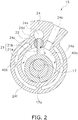
- FIG. 2 is a cross-sectional view of the compression mechanism 15 along line II-II in FIG. 1 .
- the compression mechanism 15 is configured mainly from a front head 23, a cylinder 24, a rear head 25, a piston 21, and bushings 22.
- the front head 23, the cylinder 24, and the rear head 25 are fastened integrally by bolts.
- the space above the compression mechanism 15 is a high-pressure space S1 into which refrigerant compressed by the compression mechanism 15 is discharged.
- the compression mechanism 15 is immersed in the lubricating oil, which is stored in the oil storage part 10a.
- the lubricating oil in the oil storage part 10a is supplied to the sliding parts of the compression mechanism 15 by differential pressure, etc.
- the constituent elements of the compression mechanism 15 are described next.
- the cylinder 24 includes mainly a cylinder hole 24a, an intake hole 24b, a discharge channel 24c, a bushing accommodation hole 24d, a blade accommodation hole 24e, and heat insulation holes 24f.
- the cylinder 24 is linked with the front head 23 and the rear head 25.
- An end surface on an upper side of the cylinder 24 is in contact with a lower surface of the front head 23.
- An end surface on a lower side of the cylinder 24 is in contact with an upper surface of the rear head 25.
- the cylinder 24 is formed from an Al-Si alloy.
- the Al-Si alloy which is the material of the cylinder 24, has a Si content exceeding 12.6 wt%, which is a eutectic point.
- the cylinder hole 24a is a hole that assumes the form of a column, and passes vertically through the cylinder 24 from the end surface on the upper side of the cylinder 24 toward the end surface on the lower side.
- the cylinder hole 24a is a space enclosed by an inner peripheral surface of the cylinder 24.
- the intake hole 24b is a hole that passes through along a radial direction of the cylinder 24, from an outer peripheral surface of the cylinder 24 toward the inner peripheral surface of the cylinder 24.
- the discharge channel 24c is a space formed without passing vertically through the cylinder 24, due to part of the inner peripheral surface of the cylinder 24 being cut away.
- the bushing accommodation hole 24d is a hole that passes vertically through the cylinder 24, and that is arranged between the intake hole 24b and the discharge channel 24c as viewed along the vertical direction.
- the blade accommodation hole 24e is a hole that passes vertically through the cylinder 24 and communicates with the bushing accommodation hole 24d.
- the heat insulation hole 24f is a hole that passes vertically through the cylinder 24 between the outer peripheral surface of the cylinder 24 and the inner peripheral surface of the cylinder 24.
- the cylinder 24 has a plurality of heat insulation holes 24f.
- the cylinder hole 24a accommodates an eccentric shaft part 17a of the crankshaft 17 and a roller 21 a of the piston 21.
- the bushing accommodation hole 24d accommodates a blade 21 b of the piston 21 and the bushings 22. With the blade 21 b of the piston 21 accommodated in the blade accommodation hole 24e, the discharge channel 24c is formed in the side near the front head 23.
- the piston 21 is inserted into the cylinder hole 24a of the cylinder 24.
- the piston 21 has the substantially cylindrical roller 21 a and the blade 21 b, which protrudes outward in the radial direction of the roller 21 a.
- the piston 21 is a member in which the roller 21 a and the blade 21 b are integrated.
- An end surface on an upper side of the piston 21 is in contact with the lower surface of the front head 23.
- An end surface on a lower side of the piston 21 is in contact with the upper surface of the rear head 25.
- the piston 21 is formed from an Al-Si alloy.
- the Al-Si alloy, which is the material of the piston 21, has a Si content exceeding 12.6 wt%, which is a eutectic point.
- the material of the piston 21 is the same as the material of the cylinder 24.
- the roller 21 a is inserted into the cylinder hole 24a of the cylinder 24 while being fitted into the eccentric shaft part 17a of the crankshaft 17.
- the axial rotation of the crankshaft 17 causes the roller 21 a to perform an orbiting motion about the rotational axis of the crankshaft 17.
- the roller 21 a orbits clockwise.
- the blade 21 b is accommodated in the bushing accommodation hole 24d and the blade accommodation hole 24e of the cylinder 24.
- the blade 21 b oscillates while sliding against the bushings 22.
- the blade 21 b moves back and forth along the longitudinal direction thereof.
- the compression mechanism 15 includes a compression chamber, which is a space enclosed by the cylinder 24, the piston 21, the front head 23, and the rear head 25.
- the compression chamber is sectionalized by the piston 21 into an intake chamber 40a communicating with the intake hole 24b, and a discharge chamber 40b communicating with the discharge channel 24c.
- the intake chamber 40a and the discharge chamber 40b are shown as areas enclosed by the inner peripheral surface of the cylinder 24 and the outer peripheral surface of the piston 21.
- the volumes of the intake chamber 40a and the discharge chamber 40b vary according to the position of the piston 21.
- the bushings 22 are a pair of members assuming a substantially half-column form.
- the bushings 22 are accommodated in the bushing accommodation hole 24d of the cylinder 24 as sandwiching the blade 21 b of the piston 21.
- the bushings 22 are formed from tool steel.
- FIG. 3 is an enlargement of the vicinity of the bushings 22 of FIG. 2 .
- the bushings 22 have sliding surfaces 22a that slide against the cylinder 24 and the piston 21.
- the bushings 22 have surface layers including the sliding surfaces 22a.
- the surface layers of the bushings 22 are reformed by a nitriding process.
- the nitriding process is performed by gas nitriding, ion nitriding, etc.
- the thickness of each surface layer is, e.g., 10 to 20 ⁇ m.
- the hardness of the surface layers of the bushings 22 in the sliding surfaces 22a is at least Hv 1000.
- the hardness of the surface layers of the bushings 22 is greater than the hardness of the proeutectic Si contained in the Al-Si alloy, which is the material of the cylinder 24 and the piston 21.
- the front head 23 is a member that covers the end surface on the upper side of the cylinder 24.
- the front head 23 is fastened to the casing 10 by bolts, etc.
- the front head 23 has an upper bearing part 23a for supporting the crankshaft 17.
- the front head 23 has a discharge port 23b.
- the discharge port 23b communicates with the discharge channel 24c and a high-pressure space S1.
- the discharge port 23b is a flow channel for sending refrigerant compressed by the compression mechanism 15 from the discharge chamber 40b to the high-pressure space S1.
- a discharge valve 23c which closes off an opening in an upper side of the discharge port 23b, is attached to the upper surface of the front head 23.
- the discharge valve 23c is a valve for preventing reverse flow of the refrigerant from the high-pressure space S1 to the discharge chamber 40b.
- the discharge valve 23c is lifted upward by the pressure of the refrigerant inside the discharge port 23b.
- the discharge port 23b thereby communicates with the high-pressure space S1.
- the rear head 25 is a member that covers the end surface on the lower side of the cylinder 24.
- the rear head 25 has a lower bearing part 25a for supporting the crankshaft 17.
- the cylinder hole 24a of the cylinder 24 is closed off by the front head 23 and the rear head 25.
- the drive motor 16 is a brushless DC motor accommodated inside the casing 10 and installed above the compression mechanism 15.
- the drive motor 16 is configured mainly from a stator 51 secured to an inner wall surface of the casing 10, and a rotor 52 that is rotatably accommodated in an inner side of the stator 51 with an air gap provided therebetween.
- the stator 51 has a stator core 61 and a pair of insulators 62 attached to both vertical-direction end surfaces of the stator core 61.
- the stator core 61 has a cylindrical part and a plurality of teeth (not shown) protruding radially inward from an inner peripheral surface of the cylindrical part.
- a conductive wire is wound around the teeth of the stator core 61 and the pair of insulators 62.
- a coil 72a is thereby formed on each tooth of the stator core 61.
- a plurality of notched core cut parts are provided in an outer side surface of the stator 51, from an upper end surface of the stator 51 to a lower end surface at predetermined intervals in the circumferential direction.
- the core cut parts form a motor cooling passage extending in the vertical direction between the body casing part 11 and the stator 51.
- the rotor 52 is configured from a plurality of vertically stacked metal plates.
- the rotor 52 is linked to the crankshaft 17, which passes vertically through the rotational center of the rotor.
- the rotor 52 is connected with the compression mechanism 15 via the crankshaft 17.
- the rotor 52 has a rotor core 52a configured from a plurality of vertically stacked metal plates, and a plurality of magnets 52b embedded in the rotor core 52a.
- the magnets 52b are arranged at equal intervals along the circumferential direction of the rotor core 52a.
- the crankshaft 17 is accommodated inside the casing 10 and is arranged so that the axial direction thereof extends along the vertical direction.
- the crankshaft 17 is linked to the rotor 52 of the drive motor 16 and the piston 21 of the compression mechanism 15.
- the crankshaft 17 has an eccentric shaft part 17a.
- the eccentric shaft part 17a is linked with the roller 21 a of the piston 21, which is inserted into the cylinder hole 24a of the cylinder 24.
- An end part on an upper side of the crankshaft 17 is linked with the rotor 52 of the drive motor 16.
- the crankshaft 17 is supported by the upper bearing part 23a of the front head 23 and the lower bearing part 25a of the rear head 25.
- the intake tube 19 is a tube passing through the body casing part 11 of the casing 10. An end part of the intake tube 19 that is inside the casing 10 is fitted into the intake hole 24b of the cylinder 24. An end part of the intake tube 19 that is outside the casing 10 is connected to a refrigerant circuit.
- the intake tube 19 is a tube for supplying refrigerant from the refrigerant circuit to the compression mechanism 15.
- the discharge tube 20 is a tube passing through the upper wall part 12 of the casing 10. An end part of the discharge tube 20 that is inside the casing 10 is positioned in a space above the drive motor 16. An end part of the discharge tube 20 that is outside the casing 10 is connected to the refrigerant circuit.
- the discharge tube 20 is a tube for supplying refrigerant compressed by the compression mechanism 15 to the refrigerant circuit.
- the intake chamber 40a communicating with the intake hole 24b gradually increases in volume.
- low-pressure refrigerant flows into the intake chamber 40a from outside the casing 10 through the intake tube 19.
- the intake chamber 40a becomes the discharge chamber 40b communicating with the discharge channel 24c
- the discharge chamber 40b gradually decreases in volume
- the discharge chamber again becomes the intake chamber 40a.
- the low-pressure refrigerant drawn into the intake chamber 40a from the intake tube 19 through the intake hole 24b is thereby compressed in the discharge chamber 40b.
- the high-pressure refrigerant compressed in the discharge chamber 40b is discharged through the discharge channel 24c and the discharge port 23b to the high-pressure space S1.
- the refrigerant discharged to the high-pressure space S1 passes through the motor cooling passage of the drive motor 16 and flows upward, after which the refrigerant is discharged out of the casing 10 from the discharge tube 20.
- the hardness of the sliding surfaces 22a of the bushings 22 that slide against the cylinder 24 and the piston 21 is greater than the hardness of the proeutectic Si contained in the Al-Si alloy, which is the material of the cylinder 24 and the piston 21. Wear on the sliding surfaces 22a of the bushings 22, which is caused by the proeutectic Si contained in the cylinder 24 and the piston 21, is thereby restrained. Moreover, the Si content of the Al-Si alloy, which is the material of the cylinder 24 and the piston 21, is greater than 12.6 wt%, which is a eutectic point.
- the Al-Si alloy has a high Si content
- wear on the cylinder 24 and the piston 21 is restrained. Due to the amount of wear on the cylinder 24, the piston 21, and the bushings 22 being restrained, the decrease in the reliability of the rotary compressor 101 is restrained.
- An aluminum-based material such as an Al-Si alloy is also lighter in weight than an iron-based material. Therefore, the weight of the cylinder 24 and the piston 21 can be reduced, and the entire rotary compressor 101 can be reduced in weight. Consequently, the rotary compressor 101 can be reduced in weight and increased in reliability.
- the cylinder 24 and the piston 21 are formed from same material.
- the amount of wear on the cylinder 24 is thereby made the same as the amount of wear on the piston 21, and the service life of the cylinder 24 is therefore made the same as the life of the piston 21. Consequently, the decrease in the service life of the entire rotary compressor 101 is restrained.
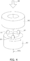
- FIG. 4 is a schematic drawing of a wear evaluation test method.
- Two types of test pieces which are blades 91 and a disc 92, are used in this test.
- the blades 91 correspond to the bushings 22, and the disc 92 corresponds to the cylinder 24 and the piston 21.
- FIG. 5 is an external view of a blade 91.
- Each blade 91 has a rounded upper surface.
- the blades 91 are secured in three locations on an upper surface of a cylindrical ring 93.
- the three blades 91 are arranged at equal intervals along the circumferential direction of the ring 93.
- the disc 92 is of cylindrical shape.
- the disc 92 is arranged above the ring 93. A lower surface of the disc 92 faces the rounded upper surfaces of the blades 91.
- the ring 93 was rotated at a constant speed of 2.0 m/s.
- a load 94 directed toward the ring 93 was applied to the disc 92 along the direction of a rotational axis 93a of the ring 93.
- the disc 92 was thereby pushed against the three blades 91 secured to the upper surface of the ring 93, and the blades 91 and the disc 92 were made to slide against each other.
- the load applied to the disc 92 at this time was 600 N.
- the load applied to the disc 92 was held for one hour.
- This test was performed in an atmosphere in which a refrigerant R410A and an ether oil FVC68D as a refrigerator oil were mixed at a ratio of 20:30.
- 17Si/A1 is an Al-Si alloy having a Si content of 17%; e.g., alloy A390 made by Showa Denko K. K.
- 11Si/Al is an Al-Si alloy having a Si content of 11%; e.g., alloy AHS2 made by Showa Denko K. K.
- FC250 is gray cast iron.
- SCM435" is chrome molybdenum steel having a carbon amount of 0.33% to 0.38%.
- SKH51 is a molybdenum-based high-speed tool steel, which is a type of tool steel.
- SKH51+DLC is a member in which a coating of diamond-like carbon (DLC) has been formed on the surface of an SKH51 member.
- SKH51+nitriding is a member in which the surface of an SKH51 member has been subjected to a nitriding process.
- FIG. 6 is a drawing for illustrating a dimension H of a linear maximum-load part P in a bushing 22 of the present evaluation test.
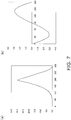
- FIG. 7 shows (a) fluctuation in the load exerted on the linear maximum-load part P during one rotation in a final product a, and (b) fluctuation in the sliding speed of a blade 21 b during one rotation.
- the linear maximum-load part P in FIG. 6 is shown in FIGS. 2 , 8 , and 9 as well.
- Example 2 an evaluation test was performed, which was for evaluating the effect that the material of the bushings 22 of the rotary compressor 101 and the load received by the bushings 22 had on the amount of wear on the bushings 22.
- Element test 400 N
- Element test 600 N
- load N/mm
- 40 Rotational speed (rps) - - 100 130 100 130 Av. sliding speed (m/s) 2.0 2.0 1.8 2.3 1.8 2.3
- the Element test (600 N) column shows the results of performing the test under the same conditions as Example 1.
- the Element test (400 N) column shows the results of performing the test under the same conditions as the Element test (600 N) except that the load applied to the disc 92 was changed from 600 N to 400 N.
- Unit maximum load maximum load units : N / dimension H of linear maximum ⁇ load part P units : mm
- the linear maximum-load part is a linear portion in the sliding surface of a bushing 22, or a blade 91 which is equivalent to the bushing 22, where the load is greatest; in other words, a linear portion in the sliding surface where the greatest load is received.
- the unit maximum load equivalent to 400 N in the element test is 33, and the unit maximum load equivalent to 600 N is 50.
- the load exerted on the linear maximum-load part P fluctuates in accordance with the rotational angle as shown in FIG. 7(a) .
- the unit maximum load is 30.
- the average sliding speed (units: m/s) is the average value of the sliding speeds of the linear maximum-load part and the cylinder 24 or the piston 21, and is the average value of the sliding speeds of the bushings 22 and the blade 21 b in the final product (the rotary compressor 101 including the compression mechanism 15 such as is shown in FIG. 2 ).
- the average sliding speed is 2.0 because the ring 93 is rotated at a constant speed of 2.0 m/s.
- the sliding speeds of the blades fluctuate in accordance with the rotational angle as shown in FIG. 7(b) .
- the average sliding speed is 1.8.
- the amount of wear on the blades 91 was successfully suppressed even though a nitriding process was performed on the steel to bring the hardness of the surface of the steel to at least Hv 1000, and even though the steel was coated with DLC to bring the hardness of the surface of the steel to at least Hv 1000.
- the amount of wear on the blades 91 was not successfully suppressed even though the steel was coated with DLC to bring the hardness of the surface of the steel to at least Hv 1000, but the amount of wear on the blades 91 was successfully suppressed by performing a nitriding process on the steel to bring the hardness of the surface of the steel to at least Hv 1000.
- design indicator (DV) unit maximum load (units: N/mm) ⁇ average sliding speed (units: m/s), even when steel coated on the surface with a DLC cover film is used as the material of the bushings 22.
- the surface layers of the bushings 22 including the sliding surfaces 22a are reformed by a nitriding process so that the hardness of the sliding surfaces 22a is at least Hv 1000.
- the surface layers of the bushings 22 may be reformed by a nitriding process so that the hardness of the sliding surfaces 22a is even higher.
- the surface layers of the bushings 22 may be reformed by a nitriding process so that the hardness of the sliding surfaces 22a is at least Hv 1200.
- the bushings 22 are formed from tool steel, but may be formed from another material of which the hardness of the surface is at least Hv 1000.
- the bushings 22 may be formed from alumina (Al 2 O 3 ), zirconia (ZrO 2 ), silicon carbide (SiC), silicon nitride (Si 3 N 4 ), boron nitride (BN), or other ceramics.
- the compression mechanism 15 is a single-cylinder compression mechanism, but may be a dual-cylinder compression mechanism.
- the compression mechanism 15 has bushings 22 that slide against the piston 21 and the cylinder 24.
- the blade 21 b of the piston 21 moves back and forth while being sandwiched on both side surfaces by the bushings 22, and the bushings 22 oscillate while sliding against the cylinder 24 and the blade 21 b of the piston 21.
- the rotary compressor 101 may have a compression mechanism 115 including a roller 121 and a vane 122 as shown in FIG. 8.
- FIG. 8 is a cross-sectional view, similar to FIG. 2 , of the compression mechanism 115.
- the compression mechanism 115 is configured mainly from the roller 121, the vane 122, a spring 123, and a cylinder 124.
- the vane 122 and the spring 123 are accommodated in a vane accommodation hole 124d.
- the rotation of the roller 121 causes the vane 122 to move back and forth in the vane accommodation hole 124d, and the spring 123 to push the vane 122 against the roller 121.
- An intake chamber 40a and a discharge chamber 40b are thereby formed in the compression mechanism 115.
- the vane 122 slides against the roller 121 and the cylinder 124.
- the vane 122 is equivalent to the bushings 22 of the present embodiment, and is formed from tool steel.
- the surface layer of the vane 122 is reformed so that the hardness of the surface of the vane 122 is at least Hv 1000.
- the surface layer of the vane 122 is either reformed by a nitriding process or coated with a DLC thin film.
- a linear maximum-load part for calculating the unit maximum load (units: N/mm) is a linear portion in the sliding surface of the vane 122 where the load is greatest, and the average sliding speed (units: m/s) is the average value of the sliding speeds of the vane 122 and the cylinder 124.
- the roller 121 and the cylinder 124 are respectively equivalent to the piston 21 and the cylinder 24 of the present embodiment, and are formed from an Al-Si alloy. This Al-Si alloy has a Si content exceeding 12.6 wt%, which is a eutectic point.
- the outer peripheral surface shape of the roller 21 a of the piston 21 is formed into a perfect circle.
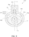
- an outer peripheral surface shape of a roller 221 a may be formed in a non-circular shape, as shown in FIG. 9 .
- an inner peripheral surface shape of a cylinder 224 is also formed in a non-circular shape.
- the outer peripheral surface shape of the roller 221 a when a blade 221 b of a piston 221 is positioned so as to extend along a line L that passes through a center O of the crankshaft 17 and is orthogonal to the crankshaft 17, the outer peripheral surface shape of the roller 221 a may be symmetrical with respect to the line L (see FIG.
- the outer peripheral surface shape of the roller 221 a may be asymmetrical with respect to the line L.
- the load received by the bushings 22 when the bushings 22 slide against the cylinder 224 and the blade 221 b of the piston 221 can be reduced more than when the outer peripheral surface shape of the roller 21 a is formed into a perfect circle.
- the compressor according to the present invention can be reduced in weight and increased in reliability.
- Patent Literature 1 Japanese Laid-open Patent Publication No. 2004-293558
Landscapes
- Engineering & Computer Science (AREA)
- Mechanical Engineering (AREA)
- General Engineering & Computer Science (AREA)
- Chemical & Material Sciences (AREA)
- Materials Engineering (AREA)
- Metallurgy (AREA)
- Organic Chemistry (AREA)
- Applications Or Details Of Rotary Compressors (AREA)
- Compressor (AREA)
- Compressors, Vaccum Pumps And Other Relevant Systems (AREA)
Abstract
Description
- The present invention relates to a compressor.
- In the past, there have been used rotary compressors in which a cylinder including a cylinder chamber and a piston accommodated in the cylinder chamber move relative to each other, thereby compressing a refrigerant. In a rotary compressor, the cylinder chamber is sectionalized into two compression chambers, and the refrigerant is compressed by the cyclic increasing and decreasing of the volumes of the compression chambers.
- A compressor including a piston having a blade is disclosed as an example of a rotary compressor in Patent Literature 1 (
Japanese Laid-open Patent Publication No. 2004-293558 - In this compressor, because the cylinder and the piston move relative to each other with the bushings therebetween, the portion where the cylinder and bushings slide against each other and the portion where the piston and bushings slide against each other must exhibit exceptional sliding and wear-resistance properties. In the past, iron-based materials have mainly been used as the materials of the cylinders and pistons constituting the sliding portions, but the use of aluminum-based materials has recently been investigated. The cylinder and the piston must be precisely machined in order to make the gap between the bushings as small as possible. With an iron-based material, cutting and a polishing process are needed in order to perform high-precision machining. With an aluminum-based material, cutting alone is sufficient for high-precision machining, and machining costs can be decreased. Furthermore, the weight of the cylinder and the piston can be reduced by changing from an iron-based material to an aluminum-based material.
- However, when a cylinder and piston made of an aluminum-based material and bushings made of an iron-based material slide against each other, a problem is presented in that slidability and wear resistance are far inferior to when members made of an iron-based material slide against each other. When an Al-Si alloy is used as an aluminum-based material for use as the material of the cylinder and the piston, there is a risk that when an alloy having a low Si content and a eutectic Si composition is used, the cylinder and the piston will experience higher wear, and there is a risk that when an alloy having a high Si content is used, the amount of wear on the bushings will increase by proeutectic Si in the alloy. When the cylinder, piston, and bushings constituting the sliding portions experience greater wear, there is a risk that the reliability of the compressor will decrease.
- An object of the present invention is to provide a compressor that can be reduced in weight and increased in reliability.
- A compressor according to a first aspect of the present invention comprises a cylinder, a piston, and a sliding member. The cylinder includes a cylinder chamber. The piston is configured to move relative to the cylinder in the cylinder chamber. The sliding member is configured to slide against the cylinder and the piston in the cylinder chamber. The cylinder and the piston are formed from an Al-Si alloy containing a Si content exceeding 12.6 wt%, which is a eutectic point. The sliding member, which is formed from steel, has a surface layer including a sliding surface that slides against the cylinder and the piston. The surface layer is reformed so as to have greater hardness than hardness of proeutectic Si contained in the Al-Si alloy. The surface layer also has hardness of at least Hv 1000 in the sliding surface.
- In this compressor, the hardness of the surface of the sliding member that slides against the cylinder and the piston is greater than the hardness of the proeutectic Si contained in the Al-Si alloy, which is the material of the cylinder and the piston, and the sliding surface has hardness of at least Hv 1000. Therefore, wear on the sliding member caused by the proeutectic Si is restrained. Because the Si content of the Al-Si alloy is high, wear on the cylinder and the piston is restrained. Moreover, an aluminum-based material such as an Al-Si alloy is lighter in weight than an iron-based material. Consequently, the compressor according to the first aspect of the present invention can be reduced in weight and increased in reliability.
- A compressor according to a second aspect of the present invention is the compressor according to the first aspect, wherein the surface layer is reformed by a nitriding process.
- A compressor according to a third aspect of the present invention is the compressor according to either the first or second aspect, wherein the reforming is a coating of a DLC thin film. The compressor is configured such that a design indicator (DV), calculated according to the formula: design indicator (DV) = unit maximum load (units: N/mm) × average sliding speed (units: m/s), is less than 67. The unit maximum load is maximum load exerted per unit length of 1 mm on a linear maximum-load part. The linear maximum-load part is a linear portion in the sliding surface where load received from the cylinder or the piston is greatest. The average sliding speed is the average value of the sliding speeds of the linear maximum-load part and either the cylinder or the piston.
- A compressor according to a fourth aspect of the present invention is the compressor according to the third aspect, wherein the surface layer has hardness of at least Hv 1200 in the sliding surface.
- A compressor according to a fifth aspect of the present invention is the compressor according to any of the first through fourth aspects, wherein the cylinder and the piston are formed from same material.
- In this compressor, the amount of wear on the cylinder and the amount of wear on the piston are of the same degree, and the service life of the cylinder is therefore of the same degree as the service life of the piston. Consequently, it is possible to restrain the decrease in the service life of the compressor according to the fifth aspect of the present invention.
- A compressor according to a sixth aspect of the present invention is the compressor according to any of the first through fifth aspects, wherein the piston has a roller and a blade secured to an outer peripheral surface of the roller. The outer peripheral surface of the roller is formed in a non-circular shape.
- A compressor according to a seventh aspect of the present invention is the compressor according to any of the first through sixth aspects, wherein the sliding member is formed from tool steel.
- A compressor according to an eighth aspect of the present invention is the compressor according to any of the first through seventh aspects, wherein the compressor is configured to use R32 as a refrigerant.
- The compressor according to the present invention can be reduced in weight and increased in reliability.
-
-
FIG. 1 is a longitudinal cross-sectional view of a rotary compressor according to an embodiment; -
FIG. 2 is a cross-sectional view of a compression mechanism along line II-II ofFIG. 1 ; -
FIG. 3 is an enlargement of the vicinity of the bushings ofFIG. 2 . -
FIG. 4 is a schematic drawing of a wear evaluation test method; -
FIG. 5 is an external view of a blade; -
FIG. 6 is a drawing for illustrating a linear maximum-load part of a bushing; -
FIG. 7 is a drawing for illustrating fluctuation of a load exerted on the linear maximum-load part during one rotation, and fluctuation of the sliding speed of a blade during one rotation, in a final product; -
FIG. 8 is a cross-sectional view of a compression mechanism in Modification D; and -
FIG. 9 is a cross-sectional view of a compression mechanism in Modification E. - A rotary compressor according to an embodiment of the present invention will be described while referring to the drawings. A rotary compressor is one in which a piston is made to rotate eccentrically within a cylinder and the volume of the space inside the cylinder is varied, whereby a refrigerant circulating through a refrigerant circuit of an air-conditioning apparatus, etc., is compressed.
-
FIG. 1 is a longitudinal cross-sectional view of arotary compressor 101 according to the present embodiment. Therotary compressor 101 comprises mainly acasing 10, acompression mechanism 15, adrive motor 16, acrankshaft 17, anintake tube 19, and adischarge tube 20. Therotary compressor 101 is a single-cylinder compressor. Examples of the refrigerant that can be used in therotary compressor 101 include R410A, R22, R32, or carbon dioxide. The constituent elements of therotary compressor 101 are described next. - The
casing 10 has a substantially cylindricalbody casing part 11, a bowl-shapedupper wall part 12 hermetically welded to an upper end part of thebody casing part 11, and a bowl-shapedbottom wall part 13 hermetically welded to a lower end part of thebody casing part 11. Thecasing 10 is formed from a rigid member that is not readily deformed or damaged when there are changes in pressure and/or temperature inside and outside thecasing 10. Thecasing 10 is installed so that the axial direction of the substantially cylindrical shape of thebody casing part 11 extends along the vertical direction. A bottom part of thecasing 10 is provided with anoil storage part 10a in which lubricating oil is stored. The lubricating oil is refrigerator oil used in order to lubricate sliding parts inside therotary compressor 101. - The
casing 10 accommodates mainly thecompression mechanism 15, thedrive motor 16, which is arranged above thecompression mechanism 15, and thecrankshaft 17, which is arranged so as to extend in the vertical direction. Thecompression mechanism 15 is linked with thedrive motor 16 by thecrankshaft 17. Theintake tube 19 and thedischarge tube 20 are hermetically welded to wall parts of thecasing 10. -
FIG. 2 is a cross-sectional view of thecompression mechanism 15 along line II-II inFIG. 1 . Thecompression mechanism 15 is configured mainly from afront head 23, acylinder 24, arear head 25, apiston 21, and bushings 22. Thefront head 23, thecylinder 24, and therear head 25 are fastened integrally by bolts. The space above thecompression mechanism 15 is a high-pressure space S1 into which refrigerant compressed by thecompression mechanism 15 is discharged. - The
compression mechanism 15 is immersed in the lubricating oil, which is stored in theoil storage part 10a. The lubricating oil in theoil storage part 10a is supplied to the sliding parts of thecompression mechanism 15 by differential pressure, etc. The constituent elements of thecompression mechanism 15 are described next. - The
cylinder 24 includes mainly acylinder hole 24a, anintake hole 24b, adischarge channel 24c, abushing accommodation hole 24d, ablade accommodation hole 24e, andheat insulation holes 24f. Thecylinder 24 is linked with thefront head 23 and therear head 25. An end surface on an upper side of thecylinder 24 is in contact with a lower surface of thefront head 23. An end surface on a lower side of thecylinder 24 is in contact with an upper surface of therear head 25. Thecylinder 24 is formed from an Al-Si alloy. The Al-Si alloy, which is the material of thecylinder 24, has a Si content exceeding 12.6 wt%, which is a eutectic point. - The
cylinder hole 24a is a hole that assumes the form of a column, and passes vertically through thecylinder 24 from the end surface on the upper side of thecylinder 24 toward the end surface on the lower side. Thecylinder hole 24a is a space enclosed by an inner peripheral surface of thecylinder 24. Theintake hole 24b is a hole that passes through along a radial direction of thecylinder 24, from an outer peripheral surface of thecylinder 24 toward the inner peripheral surface of thecylinder 24. Thedischarge channel 24c is a space formed without passing vertically through thecylinder 24, due to part of the inner peripheral surface of thecylinder 24 being cut away. Thebushing accommodation hole 24d is a hole that passes vertically through thecylinder 24, and that is arranged between theintake hole 24b and thedischarge channel 24c as viewed along the vertical direction. Theblade accommodation hole 24e is a hole that passes vertically through thecylinder 24 and communicates with thebushing accommodation hole 24d. Theheat insulation hole 24f is a hole that passes vertically through thecylinder 24 between the outer peripheral surface of thecylinder 24 and the inner peripheral surface of thecylinder 24. Thecylinder 24 has a plurality ofheat insulation holes 24f. - The
cylinder hole 24a accommodates aneccentric shaft part 17a of thecrankshaft 17 and aroller 21 a of thepiston 21. Thebushing accommodation hole 24d accommodates ablade 21 b of thepiston 21 and thebushings 22. With theblade 21 b of thepiston 21 accommodated in theblade accommodation hole 24e, thedischarge channel 24c is formed in the side near thefront head 23. - The
piston 21 is inserted into thecylinder hole 24a of thecylinder 24. Thepiston 21 has the substantiallycylindrical roller 21 a and theblade 21 b, which protrudes outward in the radial direction of theroller 21 a. Thepiston 21 is a member in which theroller 21 a and theblade 21 b are integrated. An end surface on an upper side of thepiston 21 is in contact with the lower surface of thefront head 23. An end surface on a lower side of thepiston 21 is in contact with the upper surface of therear head 25. Thepiston 21 is formed from an Al-Si alloy. The Al-Si alloy, which is the material of thepiston 21, has a Si content exceeding 12.6 wt%, which is a eutectic point. The material of thepiston 21 is the same as the material of thecylinder 24. - The
roller 21 a is inserted into thecylinder hole 24a of thecylinder 24 while being fitted into theeccentric shaft part 17a of thecrankshaft 17. The axial rotation of thecrankshaft 17 causes theroller 21 a to perform an orbiting motion about the rotational axis of thecrankshaft 17. When thecompression mechanism 15 is viewed from above, theroller 21 a orbits clockwise. - The
blade 21 b is accommodated in thebushing accommodation hole 24d and theblade accommodation hole 24e of thecylinder 24. Theblade 21 b oscillates while sliding against thebushings 22. Theblade 21 b moves back and forth along the longitudinal direction thereof. - The
compression mechanism 15 includes a compression chamber, which is a space enclosed by thecylinder 24, thepiston 21, thefront head 23, and therear head 25. The compression chamber is sectionalized by thepiston 21 into anintake chamber 40a communicating with theintake hole 24b, and adischarge chamber 40b communicating with thedischarge channel 24c. InFIG. 2 , theintake chamber 40a and thedischarge chamber 40b are shown as areas enclosed by the inner peripheral surface of thecylinder 24 and the outer peripheral surface of thepiston 21. The volumes of theintake chamber 40a and thedischarge chamber 40b vary according to the position of thepiston 21. - The
bushings 22 are a pair of members assuming a substantially half-column form. Thebushings 22 are accommodated in thebushing accommodation hole 24d of thecylinder 24 as sandwiching theblade 21 b of thepiston 21. Thebushings 22 are formed from tool steel. -
FIG. 3 is an enlargement of the vicinity of thebushings 22 ofFIG. 2 . Thebushings 22 have slidingsurfaces 22a that slide against thecylinder 24 and thepiston 21. Thebushings 22 have surface layers including the slidingsurfaces 22a. The surface layers of thebushings 22 are reformed by a nitriding process. The nitriding process is performed by gas nitriding, ion nitriding, etc. The thickness of each surface layer is, e.g., 10 to 20 µm. The hardness of the surface layers of thebushings 22 in the slidingsurfaces 22a is at least Hv 1000. The hardness of the surface layers of thebushings 22 is greater than the hardness of the proeutectic Si contained in the Al-Si alloy, which is the material of thecylinder 24 and thepiston 21. - The
front head 23 is a member that covers the end surface on the upper side of thecylinder 24. Thefront head 23 is fastened to thecasing 10 by bolts, etc. Thefront head 23 has anupper bearing part 23a for supporting thecrankshaft 17. Thefront head 23 has adischarge port 23b. Thedischarge port 23b communicates with thedischarge channel 24c and a high-pressure space S1. Thedischarge port 23b is a flow channel for sending refrigerant compressed by thecompression mechanism 15 from thedischarge chamber 40b to the high-pressure space S1. Adischarge valve 23c, which closes off an opening in an upper side of thedischarge port 23b, is attached to the upper surface of thefront head 23. Thedischarge valve 23c is a valve for preventing reverse flow of the refrigerant from the high-pressure space S1 to thedischarge chamber 40b. Thedischarge valve 23c is lifted upward by the pressure of the refrigerant inside thedischarge port 23b. Thedischarge port 23b thereby communicates with the high-pressure space S1. - The
rear head 25 is a member that covers the end surface on the lower side of thecylinder 24. Therear head 25 has alower bearing part 25a for supporting thecrankshaft 17. Thecylinder hole 24a of thecylinder 24 is closed off by thefront head 23 and therear head 25. - The
drive motor 16 is a brushless DC motor accommodated inside thecasing 10 and installed above thecompression mechanism 15. Thedrive motor 16 is configured mainly from astator 51 secured to an inner wall surface of thecasing 10, and arotor 52 that is rotatably accommodated in an inner side of thestator 51 with an air gap provided therebetween. - The
stator 51 has astator core 61 and a pair ofinsulators 62 attached to both vertical-direction end surfaces of thestator core 61. Thestator core 61 has a cylindrical part and a plurality of teeth (not shown) protruding radially inward from an inner peripheral surface of the cylindrical part. A conductive wire is wound around the teeth of thestator core 61 and the pair ofinsulators 62. Acoil 72a is thereby formed on each tooth of thestator core 61. - A plurality of notched core cut parts (not shown) are provided in an outer side surface of the
stator 51, from an upper end surface of thestator 51 to a lower end surface at predetermined intervals in the circumferential direction. The core cut parts form a motor cooling passage extending in the vertical direction between thebody casing part 11 and thestator 51. - The
rotor 52 is configured from a plurality of vertically stacked metal plates. Therotor 52 is linked to thecrankshaft 17, which passes vertically through the rotational center of the rotor. Therotor 52 is connected with thecompression mechanism 15 via thecrankshaft 17. - The
rotor 52 has arotor core 52a configured from a plurality of vertically stacked metal plates, and a plurality ofmagnets 52b embedded in therotor core 52a. Themagnets 52b are arranged at equal intervals along the circumferential direction of therotor core 52a. - The
crankshaft 17 is accommodated inside thecasing 10 and is arranged so that the axial direction thereof extends along the vertical direction. Thecrankshaft 17 is linked to therotor 52 of thedrive motor 16 and thepiston 21 of thecompression mechanism 15. Thecrankshaft 17 has aneccentric shaft part 17a. Theeccentric shaft part 17a is linked with theroller 21 a of thepiston 21, which is inserted into thecylinder hole 24a of thecylinder 24. An end part on an upper side of thecrankshaft 17 is linked with therotor 52 of thedrive motor 16. Thecrankshaft 17 is supported by theupper bearing part 23a of thefront head 23 and thelower bearing part 25a of therear head 25. - The
intake tube 19 is a tube passing through thebody casing part 11 of thecasing 10. An end part of theintake tube 19 that is inside thecasing 10 is fitted into theintake hole 24b of thecylinder 24. An end part of theintake tube 19 that is outside thecasing 10 is connected to a refrigerant circuit. Theintake tube 19 is a tube for supplying refrigerant from the refrigerant circuit to thecompression mechanism 15. - The
discharge tube 20 is a tube passing through theupper wall part 12 of thecasing 10. An end part of thedischarge tube 20 that is inside thecasing 10 is positioned in a space above thedrive motor 16. An end part of thedischarge tube 20 that is outside thecasing 10 is connected to the refrigerant circuit. Thedischarge tube 20 is a tube for supplying refrigerant compressed by thecompression mechanism 15 to the refrigerant circuit. - The operation of the
rotary compressor 101 shall be described. When thedrive motor 16 starts up, theeccentric shaft part 17a of thecrankshaft 17 rotates eccentrically about the rotational axis of thecrankshaft 17. Theroller 21 a of thepiston 21 linked to theeccentric shaft part 17a thereby orbits in thecylinder hole 24a. Theroller 21 a orbits while the outer peripheral surface of thepiston 21 comes into contact with the inner peripheral surface of thecylinder 24. Due to the orbiting of theroller 21 a, theblade 21 b of thepiston 21 moves back and forth while both side surfaces of the blade are sandwiched between the bushings 22. Thebushings 22 oscillate within thebushing accommodation hole 24d while sliding against thecylinder 24 and theblade 21 b of thepiston 21. - As the
roller 21 a orbits, theintake chamber 40a communicating with theintake hole 24b gradually increases in volume. At this time, low-pressure refrigerant flows into theintake chamber 40a from outside thecasing 10 through theintake tube 19. Along with the orbiting of theroller 21 a, theintake chamber 40a becomes thedischarge chamber 40b communicating with thedischarge channel 24c, thedischarge chamber 40b gradually decreases in volume, and the discharge chamber again becomes theintake chamber 40a. The low-pressure refrigerant drawn into theintake chamber 40a from theintake tube 19 through theintake hole 24b is thereby compressed in thedischarge chamber 40b. The high-pressure refrigerant compressed in thedischarge chamber 40b is discharged through thedischarge channel 24c and thedischarge port 23b to the high-pressure space S1. The refrigerant discharged to the high-pressure space S1 passes through the motor cooling passage of thedrive motor 16 and flows upward, after which the refrigerant is discharged out of thecasing 10 from thedischarge tube 20. - In the
rotary compressor 101 according to the present embodiment, the hardness of the slidingsurfaces 22a of thebushings 22 that slide against thecylinder 24 and thepiston 21 is greater than the hardness of the proeutectic Si contained in the Al-Si alloy, which is the material of thecylinder 24 and thepiston 21. Wear on the slidingsurfaces 22a of thebushings 22, which is caused by the proeutectic Si contained in thecylinder 24 and thepiston 21, is thereby restrained. Moreover, the Si content of the Al-Si alloy, which is the material of thecylinder 24 and thepiston 21, is greater than 12.6 wt%, which is a eutectic point. Thus, because the Al-Si alloy has a high Si content, wear on thecylinder 24 and thepiston 21 is restrained. Due to the amount of wear on thecylinder 24, thepiston 21, and thebushings 22 being restrained, the decrease in the reliability of therotary compressor 101 is restrained. An aluminum-based material such as an Al-Si alloy is also lighter in weight than an iron-based material. Therefore, the weight of thecylinder 24 and thepiston 21 can be reduced, and the entirerotary compressor 101 can be reduced in weight. Consequently, therotary compressor 101 can be reduced in weight and increased in reliability. - In the
rotary compressor 101, thecylinder 24 and thepiston 21 are formed from same material. The amount of wear on thecylinder 24 is thereby made the same as the amount of wear on thepiston 21, and the service life of thecylinder 24 is therefore made the same as the life of thepiston 21. Consequently, the decrease in the service life of the entirerotary compressor 101 is restrained. - The following is a description of a wear evaluation test performed in order to evaluate the amount of wear of the
cylinder 24, thepiston 21, and thebushings 22 of therotary compressor 101. -
FIG. 4 is a schematic drawing of a wear evaluation test method. Two types of test pieces, which areblades 91 and adisc 92, are used in this test. Theblades 91 correspond to thebushings 22, and thedisc 92 corresponds to thecylinder 24 and thepiston 21.FIG. 5 is an external view of ablade 91. Eachblade 91 has a rounded upper surface. Theblades 91 are secured in three locations on an upper surface of acylindrical ring 93. The threeblades 91 are arranged at equal intervals along the circumferential direction of thering 93. Thedisc 92 is of cylindrical shape. Thedisc 92 is arranged above thering 93. A lower surface of thedisc 92 faces the rounded upper surfaces of theblades 91. - In this test, first, the
ring 93 was rotated at a constant speed of 2.0 m/s. Next, aload 94 directed toward thering 93 was applied to thedisc 92 along the direction of arotational axis 93a of thering 93. Thedisc 92 was thereby pushed against the threeblades 91 secured to the upper surface of thering 93, and theblades 91 and thedisc 92 were made to slide against each other. The load applied to thedisc 92 at this time was 600 N. The load applied to thedisc 92 was held for one hour. This test was performed in an atmosphere in which a refrigerant R410A and an ether oil FVC68D as a refrigerator oil were mixed at a ratio of 20:30. The frictional coefficient in the sliding surfaces of theblades 91 and thedisc 92 was measured at this time. After the test had ended, the amount of wear on theblades 91 and thedisc 92 was measured. Table 1 below shows the measurement results of the wear evaluation test.[TABLE 1] Sample Material (hardness) Frictional Coefficient Amount of wear (mm3) Disc Blades Disc Blades A 17Si/Al (HRB88) SCM435 (Hv500) 0.043 0.24 0.0018 B 17Si/Al (HRB88) SKH51+DLC (Hv1500) 0.029 0 0.0033 C 11Si/Al (HRB86) SCM435 (Hv500) >0.07 galling D 11Si/Al (HRB86) SKH51+DLC (Hv1500) >0.07 galling E 11Si/Al (HRB86) SKH51+nitriding (Hv1100) 0.06 0.57 0.0056 F 17Si/Al (HRB88) SKH51+nitriding (Hv1050) 0.048 0.24 0.00042 G 17Si/Al (HRB88) SKH51+nitriding (Hv1200) 0.048 0.24 0.00037 H FC250 (HB200) SCM435 (Hv500) 0.065 0.26 0.00065 - In Table 1 above, "17Si/A1" is an Al-Si alloy having a Si content of 17%; e.g., alloy A390 made by Showa Denko K. K. "11Si/Al" is an Al-Si alloy having a Si content of 11%; e.g., alloy AHS2 made by Showa Denko K. K. "FC250" is gray cast iron. "SCM435" is chrome molybdenum steel having a carbon amount of 0.33% to 0.38%. "SKH51" is a molybdenum-based high-speed tool steel, which is a type of tool steel. "SKH51+DLC" is a member in which a coating of diamond-like carbon (DLC) has been formed on the surface of an SKH51 member. "SKH51+nitriding" is a member in which the surface of an SKH51 member has been subjected to a nitriding process.
- Comparing sample A and sample H, a combination of steel and an aluminum alloy (17Si/Al) with a Si content higher than the eutectic point (sample A) had greater amount of wear on the
blades 91 than a combination of cast iron and steel (sample H). - Comparing sample A and sample B, coating the steel with the DLC caused the frictional coefficient to decrease, but also increased the amount of wear on the
blades 91. This was presumably due to the surfaces of theblades 91 being worn by the proeutectic Si; i.e., hard particles contained in the aluminum alloy constituting the material of thedisc 92. - Comparing sample A and sample C, the frictional coefficient increased and galling occurred as a result of using an aluminum alloy (11 Si/Al) having a Si content lower than the eutectic point in order to reduce the amount of wear on the surfaces of the
blades 91 due to the proeutectic Si. Comparing sample B and sample D, the same tendency was confirmed. - Comparing sample A and samples F and G, performing a nitriding process on the steel and bringing the hardness of the surface of the steel to at least Hv 1000 caused the amount of wear on the
blades 91 to decrease, with little change to the frictional coefficient and the amount of wear on thedisc 92. Comparing sample F and sample G indicates that the amount of wear on theblades 91 decreased in correspondence with an increase in the hardness of the surface of the steel. - Comparing sample E and samples F and G, the frictional coefficient increased and the amount of wear on the
disc 92 and theblades 91 also increased when an aluminum alloy (11Si/Al) having a Si content lower than the eutectic point was used, even in cases in which a nitriding process had been performed on the steel. - The above results confirmed that the frictional coefficient and the amount of wear on the
disc 92 and theblades 91 can be suppressed by using an aluminum alloy (17Si/Al) having a Si content higher than the eutectic point as the material of thedisc 92 and using steel whose surface has been subjected to a nitriding process as the material of theblades 91. It was also confirmed that the amount of wear on theblades 91 decreases in correspondence with an increase in the hardness of the surface of the steel constituting the material of theblades 91. -
FIG. 6 is a drawing for illustrating a dimension H of a linear maximum-load part P in abushing 22 of the present evaluation test.FIG. 7 shows (a) fluctuation in the load exerted on the linear maximum-load part P during one rotation in a final product a, and (b) fluctuation in the sliding speed of ablade 21 b during one rotation. The linear maximum-load part P inFIG. 6 is shown inFIGS. 2 ,8 , and9 as well. - In Example 2, an evaluation test was performed, which was for evaluating the effect that the material of the
bushings 22 of therotary compressor 101 and the load received by thebushings 22 had on the amount of wear on thebushings 22.[TABLE 2] Element test (400 N) Element test (600 N) Fin.Pro.a Fin.Pro.b Fin.Pro.c Fin.Pro.d Unit max. load (N/mm) 33 50 30 30 40 40 Rotational speed (rps) - - 100 130 100 130 Av. sliding speed (m/s) 2.0 2.0 1.8 2.3 1.8 2.3 Unit max. load × av. sliding speed 67 100 54 69 72 92 DLC coating ○ × ○ × × × Nitriding process ○ ○ ○ ○ ○ ○ - In Table 2, the Element test (600 N) column shows the results of performing the test under the same conditions as Example 1. In Table 2, the Element test (400 N) column shows the results of performing the test under the same conditions as the Element test (600 N) except that the load applied to the
disc 92 was changed from 600 N to 400 N. - In Table 2, the unit maximum load (units: N/mm) is represented by the following formula.

- The linear maximum-load part is a linear portion in the sliding surface of a
bushing 22, or ablade 91 which is equivalent to thebushing 22, where the load is greatest; in other words, a linear portion in the sliding surface where the greatest load is received. The unit maximum load equivalent to 400 N in the element test, is 33, and the unit maximum load equivalent to 600 N is 50. In the final products, the load exerted on the linear maximum-load part P fluctuates in accordance with the rotational angle as shown inFIG. 7(a) . For example, in the final product a, the unit maximum load is 30. - In Table 2, the average sliding speed (units: m/s) is the average value of the sliding speeds of the linear maximum-load part and the
cylinder 24 or thepiston 21, and is the average value of the sliding speeds of thebushings 22 and theblade 21 b in the final product (therotary compressor 101 including thecompression mechanism 15 such as is shown inFIG. 2 ). In the element test, the average sliding speed is 2.0 because thering 93 is rotated at a constant speed of 2.0 m/s. In the final products, the sliding speeds of the blades fluctuate in accordance with the rotational angle as shown inFIG. 7(b) . For example, in the final product a, the average sliding speed is 1.8. - In the element test (400 N), the amount of wear on the
blades 91 was successfully suppressed even though a nitriding process was performed on the steel to bring the hardness of the surface of the steel to at least Hv 1000, and even though the steel was coated with DLC to bring the hardness of the surface of the steel to at least Hv 1000. - In the element test (600 N), the amount of wear on the
blades 91 was not successfully suppressed even though the steel was coated with DLC to bring the hardness of the surface of the steel to at least Hv 1000, but the amount of wear on theblades 91 was successfully suppressed by performing a nitriding process on the steel to bring the hardness of the surface of the steel to at least Hv 1000. - Comparing the final product a with the element test (400 N) and the element test (600 N), with the final product a, in which both the unit maximum load and the average sliding speed were less than in the element test (400 N) and the element test (600 N), the amount of wear on the
bushings 22 was successfully suppressed even though a nitriding process was performed on the steel to bring the hardness of the surface of the steel to at least Hv 1000, and even though the steel was coated with DLC to bring the hardness of the surface of the steel to at least Hv 1000. - Comparing the final product b with the element test (400 N) and the element test (600 N), with the final product b, in which the unit maximum load was less and the average sliding speed was greater than in the element test (400 N) and the element test (600 N), the amount of wear on the
bushings 22 was not successfully suppressed even though the steel was coated with DLC to bring the hardness of the surface of the steel to at least Hv 1000, but the amount of wear on thebushings 22 was successfully suppressed by performing a nitriding process on the steel to bring the hardness of the surface of the steel to at least Hv 1000. - Comparing the final product c with the element test (400 N) and the element test (600 N), with the final product c, in which the average sliding speed was less than in the element test (400 N) and the element test (600 N) and the unit maximum load was greater than in the element test (400 N) and less than in the element test (600 N), the amount of wear on the
bushings 22 was not successfully suppressed even though the steel was coated with DLC to bring the hardness of the surface of the steel to at least Hv 1000, but the amount of wear on thebushings 22 was successfully suppressed by performing a nitriding process on the steel to bring the hardness of the surface of the steel to at least Hv 1000. - Comparing the final product d with the element test (400 N) and the element test (600 N), with the final product d, in which the average sliding speed was greater than in the element test (400 N) and the element test (600 N) and the unit maximum load was greater than in the element test (400 N) and less than in the element test (600 N), the amount of wear on the
bushings 22 was not successfully suppressed even though the steel was coated with DLC to bring the hardness of the surface of the steel to at least Hv 1000, but the amount of wear on thebushings 22 was successfully suppressed by performing a nitriding process on the steel to bring the hardness of the surface of the steel to at least Hv 1000. - It was confirmed from the above results that the amount of wear on the
bushings 22 could be suppressed if an aluminum alloy (17Si/Al) having a Si content higher than the eutectic point is used as the material of thecylinder 24 and thepiston 21 of therotary compressor 101 and a design indicator (DV) is less than 67 as calculated by the formula: design indicator (DV) = unit maximum load (units: N/mm) × average sliding speed (units: m/s), even when steel coated on the surface with a DLC cover film is used as the material of thebushings 22. - The specific configuration of the present embodiment can be altered within a range that does not deviate from the scope of the present invention. Modifications that can be applied to the present embodiment are described below.
- In the present embodiment, the surface layers of the
bushings 22 including the slidingsurfaces 22a are reformed by a nitriding process so that the hardness of the slidingsurfaces 22a is at least Hv 1000. However, the surface layers of thebushings 22 may be reformed by a nitriding process so that the hardness of the slidingsurfaces 22a is even higher. For example, the surface layers of thebushings 22 may be reformed by a nitriding process so that the hardness of the slidingsurfaces 22a is at least Hv 1200. - In the present embodiment, the
bushings 22 are formed from tool steel, but may be formed from another material of which the hardness of the surface is at least Hv 1000. For example, thebushings 22 may be formed from alumina (Al2O3), zirconia (ZrO2), silicon carbide (SiC), silicon nitride (Si3N4), boron nitride (BN), or other ceramics. - In the present embodiment, the
compression mechanism 15 is a single-cylinder compression mechanism, but may be a dual-cylinder compression mechanism. - In the present embodiment, the
compression mechanism 15 hasbushings 22 that slide against thepiston 21 and thecylinder 24. In thiscompression mechanism 15, theblade 21 b of thepiston 21 moves back and forth while being sandwiched on both side surfaces by thebushings 22, and thebushings 22 oscillate while sliding against thecylinder 24 and theblade 21 b of thepiston 21. - However, the
rotary compressor 101 may have acompression mechanism 115 including aroller 121 and avane 122 as shown inFIG. 8. FIG. 8 is a cross-sectional view, similar toFIG. 2 , of thecompression mechanism 115. InFIG. 8 , the same constituent elements as those inFIG. 2 are indicated by the same reference symbols. Thecompression mechanism 115 is configured mainly from theroller 121, thevane 122, aspring 123, and acylinder 124. Thevane 122 and thespring 123 are accommodated in avane accommodation hole 124d. The rotation of theroller 121 causes thevane 122 to move back and forth in thevane accommodation hole 124d, and thespring 123 to push thevane 122 against theroller 121. Anintake chamber 40a and adischarge chamber 40b are thereby formed in thecompression mechanism 115. - In the present modification, the
vane 122 slides against theroller 121 and thecylinder 124. Thevane 122 is equivalent to thebushings 22 of the present embodiment, and is formed from tool steel. The surface layer of thevane 122 is reformed so that the hardness of the surface of thevane 122 is at least Hv 1000. Specifically, the surface layer of thevane 122 is either reformed by a nitriding process or coated with a DLC thin film. When the surface layer of thevane 122 is coated with a DLC thin film, the design indicator (DV) must be less than 67 as calculated by the formula: design indicator (DV) = unit maximum load (units: N/mm) × average sliding speed (units: m/s). In therotary compressor 101 including thecompression mechanism 115 such as that shown inFIG. 8 , a linear maximum-load part for calculating the unit maximum load (units: N/mm) is a linear portion in the sliding surface of thevane 122 where the load is greatest, and the average sliding speed (units: m/s) is the average value of the sliding speeds of thevane 122 and thecylinder 124. Theroller 121 and thecylinder 124 are respectively equivalent to thepiston 21 and thecylinder 24 of the present embodiment, and are formed from an Al-Si alloy. This Al-Si alloy has a Si content exceeding 12.6 wt%, which is a eutectic point. - In the
compression mechanism 15 of the present embodiment, the outer peripheral surface shape of theroller 21 a of thepiston 21 is formed into a perfect circle. - However, in a
compression mechanism 215 of therotary compressor 101, an outer peripheral surface shape of aroller 221 a may be formed in a non-circular shape, as shown inFIG. 9 . In this case, an inner peripheral surface shape of acylinder 224 is also formed in a non-circular shape. Concerning the shape of theroller 221 a, when ablade 221 b of apiston 221 is positioned so as to extend along a line L that passes through a center O of thecrankshaft 17 and is orthogonal to thecrankshaft 17, the outer peripheral surface shape of theroller 221 a may be symmetrical with respect to the line L (seeFIG. 9 ), or the outer peripheral surface shape of theroller 221 a may be asymmetrical with respect to the line L. Thus, due to the outer peripheral surface shape of theroller 221 a being formed in a non-circular shape, the load received by thebushings 22 when thebushings 22 slide against thecylinder 224 and theblade 221 b of thepiston 221 can be reduced more than when the outer peripheral surface shape of theroller 21 a is formed into a perfect circle. - The compressor according to the present invention can be reduced in weight and increased in reliability.
-
- 21
- Piston
- 22
- Bushing (sliding member)
- 22a
- Sliding surface
- 24
- Cylinder
- 24a
- Cylinder hole (cylinder chamber)
- 101
- Rotary compressor (compressor)
- Patent Literature 1:
Japanese Laid-open Patent Publication No. 2004-293558
Claims (8)
- A compressor (101) comprising:a cylinder (24, 124) including a cylinder chamber (24a);a piston (21, 121) configured to move relative to the cylinder in the cylinder chamber; anda sliding member (22, 122) configured to slide against the cylinder and the piston in the cylinder chamber;the cylinder and the piston being formed from an Al-Si alloy containing a Si content exceeding 12.6 wt%, which is a eutectic point;the sliding member being formed from steel and having a surface layer including a sliding surface (22a) that slides against the cylinder and the piston; andthe surface layer being reformed so as to have greater hardness than hardness of proeutectic Si contained in the Al-Si alloy, and having hardness of at least Hv 1000 in the sliding surface.
- The compressor according to claim 1, whereinthe surface layer is reformed by a nitriding process.
- The compressor according to claim 1, whereinthe compressor is configured such that a design indicator (DV), calculated from:a unit maximum load (units: N/mm), which is maximum load exerted per unit length of 1 mm on a linear maximum-load part, which is a linear portion in the sliding surface where load received from the cylinder or the piston is greatest, andan average sliding speed (units: m/s), which is the average value of the sliding speeds of the linear maximum-load part and either the cylinder or the piston,the design indicator being calculated according to the formula:design indicator (DV) = unit maximum load × average sliding speed, is less than 67; andthe reforming involves applying a DLC thin-film coating.
- The compressor according to any of claims 1 to 3, whereinthe surface layer has hardness of at least Hv 1200 in the sliding surface.
- The compressor according to any of claims 1 to 4, whereinthe cylinder and the piston are formed from same material.
- The compressor according to any of claims 1 to 5, whereinthe piston has a roller and a blade secured to an outer peripheral surface of the roller; andan outer peripheral surface shape of the roller is formed in a non-circular shape.
- The compressor according to any of claims 1 to 6, whereinthe sliding member is formed from tool steel.
- The compressor according to any of claims 1 to 7, wherein
the compressor is configured to use R32 is as a refrigerant.
Applications Claiming Priority (2)
| Application Number | Priority Date | Filing Date | Title |
|---|---|---|---|
| JP2014098447 | 2014-05-12 | ||
| PCT/JP2015/063596 WO2015174400A1 (en) | 2014-05-12 | 2015-05-12 | Compressor |
Publications (3)
| Publication Number | Publication Date |
|---|---|
| EP3128175A1 true EP3128175A1 (en) | 2017-02-08 |
| EP3128175A4 EP3128175A4 (en) | 2017-03-08 |
| EP3128175B1 EP3128175B1 (en) | 2018-12-12 |
Family
ID=54479938
Family Applications (1)
| Application Number | Title | Priority Date | Filing Date |
|---|---|---|---|
| EP15792238.6A Active EP3128175B1 (en) | 2014-05-12 | 2015-05-12 | Compressor |
Country Status (7)
| Country | Link |
|---|---|
| US (1) | US10294941B2 (en) |
| EP (1) | EP3128175B1 (en) |
| JP (1) | JP6028832B2 (en) |
| CN (1) | CN106415013B (en) |
| ES (1) | ES2715112T3 (en) |
| TR (1) | TR201903313T4 (en) |
| WO (1) | WO2015174400A1 (en) |
Families Citing this family (7)
| Publication number | Priority date | Publication date | Assignee | Title |
|---|---|---|---|---|
| WO2017138175A1 (en) * | 2016-02-12 | 2017-08-17 | 東芝キヤリア株式会社 | Rotary compressor and refrigeration cycle device |
| JP6428739B2 (en) * | 2016-09-30 | 2018-11-28 | 株式会社富士通ゼネラル | Compressor |
| WO2020089666A1 (en) * | 2018-11-02 | 2020-05-07 | 日産自動車株式会社 | Thermal spray coating for sliding member, and sliding device provided with thermal spray coating for sliding member |
| US11585289B2 (en) * | 2018-11-02 | 2023-02-21 | Nissan Motor Co., Ltd. | Thermally sprayed coating for sliding member and sliding device provided with said thermally sprayed coating for sliding member |
| JP7431105B2 (en) * | 2020-05-28 | 2024-02-14 | 株式会社日立産機システム | compressor |
| CN112160906B (en) * | 2020-09-14 | 2022-08-16 | 珠海格力节能环保制冷技术研究中心有限公司 | Friction pair structure, design method and compressor |
| CN115681156A (en) * | 2021-07-23 | 2023-02-03 | 上海海立电器有限公司 | Cylinder and compressor |
Family Cites Families (18)
| Publication number | Priority date | Publication date | Assignee | Title |
|---|---|---|---|---|
| JPS5548584B2 (en) * | 1974-01-31 | 1980-12-06 | ||
| JPS63307250A (en) * | 1987-06-05 | 1988-12-14 | Mitsubishi Metal Corp | Vane material for rotary compressor |
| US5106436A (en) * | 1991-09-30 | 1992-04-21 | General Motors Corporation | Wear resistant eutectic aluminum-silicon alloy |
| JPH05312168A (en) * | 1992-05-08 | 1993-11-22 | Matsushita Refrig Co Ltd | Compressor |
| JPH07293468A (en) * | 1994-04-28 | 1995-11-07 | Toshiba Corp | Hermetic compressor |
| US5591023A (en) * | 1995-10-10 | 1997-01-07 | Hitachi Metals, Ltd. | Rotary type compressor |
| JPH09176770A (en) * | 1995-12-27 | 1997-07-08 | Daikin Ind Ltd | Alternative refrigerant compatible compressor components |
| TW408212B (en) * | 1996-10-11 | 2000-10-11 | Sanyo Electric Co | Method for treating metal surface, rotary shaft and vane for refrigerant compressor treated by the method, and refrigerant compressor using the same |
| JPH11257225A (en) * | 1998-03-13 | 1999-09-21 | Mitsubishi Electric Corp | Coated sliding material, method for producing the same, and refrigerator / air conditioner using the sliding material |
| JP2001271741A (en) * | 2000-03-24 | 2001-10-05 | Taiho Kogyo Co Ltd | Swash plate compressor shoe and swash plate compressor |
| JP4232705B2 (en) | 2004-07-20 | 2009-03-04 | ダイキン工業株式会社 | Swing compressor |
| JP2006057674A (en) * | 2004-08-18 | 2006-03-02 | Riken Corp | Sliding member and piston ring |
| JP4898162B2 (en) * | 2005-07-25 | 2012-03-14 | 東芝キヤリア株式会社 | Hermetic compressor and refrigeration cycle apparatus |
| JP4743067B2 (en) * | 2006-09-29 | 2011-08-10 | 株式会社デンソー | Scroll compressor |
| US7878777B2 (en) | 2006-08-25 | 2011-02-01 | Denso Corporation | Scroll compressor having grooved thrust bearing |
| JP5294719B2 (en) * | 2008-06-17 | 2013-09-18 | 三菱電機株式会社 | Rotary compressor |
| JP2012149553A (en) * | 2011-01-18 | 2012-08-09 | Daikin Industries Ltd | Rotary compressor |
| JP6127722B2 (en) * | 2012-05-28 | 2017-05-17 | ダイキン工業株式会社 | Rotary compressor |
-
2015
- 2015-05-07 JP JP2015094666A patent/JP6028832B2/en active Active
- 2015-05-12 ES ES15792238T patent/ES2715112T3/en active Active
- 2015-05-12 US US15/309,931 patent/US10294941B2/en active Active
- 2015-05-12 WO PCT/JP2015/063596 patent/WO2015174400A1/en not_active Ceased
- 2015-05-12 CN CN201580024534.0A patent/CN106415013B/en active Active
- 2015-05-12 TR TR2019/03313T patent/TR201903313T4/en unknown
- 2015-05-12 EP EP15792238.6A patent/EP3128175B1/en active Active
Also Published As
| Publication number | Publication date |
|---|---|
| JP6028832B2 (en) | 2016-11-24 |
| JP2015232322A (en) | 2015-12-24 |
| TR201903313T4 (en) | 2019-04-22 |
| CN106415013B (en) | 2018-12-21 |
| ES2715112T3 (en) | 2019-05-31 |
| US10294941B2 (en) | 2019-05-21 |
| EP3128175A4 (en) | 2017-03-08 |
| EP3128175B1 (en) | 2018-12-12 |
| CN106415013A (en) | 2017-02-15 |
| WO2015174400A1 (en) | 2015-11-19 |
| US20170218954A1 (en) | 2017-08-03 |
Similar Documents
| Publication | Publication Date | Title |
|---|---|---|
| EP3128175B1 (en) | Compressor | |
| US8186982B2 (en) | Adjustable rotary pump with reduced wear | |
| JP4661801B2 (en) | Scroll compressor and method for manufacturing the same | |
| US20100061871A1 (en) | Compressor slider, slider preform, scroll part, and compressor | |
| US8075289B2 (en) | Scroll-type fluid machine including thrust receiving device | |
| JP5642297B2 (en) | Vane type compressor | |
| EP1876356A1 (en) | Scroll fluid machine | |
| JP2014163332A (en) | Scroll compressor | |
| JP2001065458A (en) | Compressor | |
| EP2541065A1 (en) | Scroll compressor | |
| EP2775155A1 (en) | Radial roller bearing, rotary machine using radial roller bearing, and method for designing radial roller bearing | |
| EP2390463B1 (en) | Bearings of the shaft of a hermetic compressor | |
| JP4069839B2 (en) | Sliding device, manufacturing method thereof, and refrigerant compressor | |
| WO2015025416A1 (en) | Rotary machine and refrigeration cycle device | |
| KR0185253B1 (en) | Rotary compressor and blade tip structure | |
| JPH02136586A (en) | Vane type compressor | |
| US20210389030A1 (en) | Refrigerant compressor and freezer including same | |
| JP2003314477A (en) | Rotary pump | |
| US20050207926A1 (en) | Scroll compressor | |
| JPH05113181A (en) | Scroll fluid compressor | |
| JPH01178788A (en) | Refrigerant compressor | |
| JP2007205271A (en) | Rotary fluid machine | |
| JPS6123887A (en) | Rotary compressor | |
| JPH0476294A (en) | Fluid compressor | |
| JPH01113589A (en) | Vane-type compressor |
Legal Events
| Date | Code | Title | Description |
|---|---|---|---|
| STAA | Information on the status of an ep patent application or granted ep patent |
Free format text: STATUS: THE INTERNATIONAL PUBLICATION HAS BEEN MADE |
|
| PUAI | Public reference made under article 153(3) epc to a published international application that has entered the european phase |
Free format text: ORIGINAL CODE: 0009012 |
|
| STAA | Information on the status of an ep patent application or granted ep patent |
Free format text: STATUS: REQUEST FOR EXAMINATION WAS MADE |
|
| 17P | Request for examination filed |
Effective date: 20161103 |
|
| AK | Designated contracting states |
Kind code of ref document: A1 Designated state(s): AL AT BE BG CH CY CZ DE DK EE ES FI FR GB GR HR HU IE IS IT LI LT LU LV MC MK MT NL NO PL PT RO RS SE SI SK SM TR |
|
| AX | Request for extension of the european patent |
Extension state: BA ME |
|
| A4 | Supplementary search report drawn up and despatched |
Effective date: 20170208 |
|
| RIC1 | Information provided on ipc code assigned before grant |
Ipc: C23C 14/06 20060101ALI20170202BHEP Ipc: C23C 28/04 20060101ALI20170202BHEP Ipc: F04C 18/00 20060101ALI20170202BHEP Ipc: C22C 21/02 20060101ALI20170202BHEP Ipc: F04C 18/32 20060101ALI20170202BHEP Ipc: F04C 29/00 20060101AFI20170202BHEP |
|
| DAV | Request for validation of the european patent (deleted) | ||
| DAX | Request for extension of the european patent (deleted) | ||
| STAA | Information on the status of an ep patent application or granted ep patent |
Free format text: STATUS: EXAMINATION IS IN PROGRESS |
|
| 17Q | First examination report despatched |
Effective date: 20171116 |
|
| REG | Reference to a national code |
Ref country code: DE Ref legal event code: R079 Ref document number: 602015021578 Country of ref document: DE Free format text: PREVIOUS MAIN CLASS: F04C0029000000 Ipc: F04C0023000000 |
|
| GRAP | Despatch of communication of intention to grant a patent |
Free format text: ORIGINAL CODE: EPIDOSNIGR1 |
|
| STAA | Information on the status of an ep patent application or granted ep patent |
Free format text: STATUS: GRANT OF PATENT IS INTENDED |
|
| RIC1 | Information provided on ipc code assigned before grant |
Ipc: C23C 14/06 20060101ALI20180524BHEP Ipc: F04C 18/32 20060101ALI20180524BHEP Ipc: C23C 28/04 20060101ALI20180524BHEP Ipc: F04C 18/356 20060101ALI20180524BHEP Ipc: C22C 21/02 20060101ALI20180524BHEP Ipc: F04C 23/00 20060101AFI20180524BHEP Ipc: F04C 29/00 20060101ALI20180524BHEP Ipc: F04C 18/00 20060101ALI20180524BHEP |
|
| INTG | Intention to grant announced |
Effective date: 20180607 |
|
| RIN1 | Information on inventor provided before grant (corrected) |
Inventor name: FURUSHO, KAZUHIRO Inventor name: OHKAWA, TAKEYOSHI Inventor name: NISHIMURA, KOUSUKE |
|
| GRAS | Grant fee paid |
Free format text: ORIGINAL CODE: EPIDOSNIGR3 |
|
| GRAJ | Information related to disapproval of communication of intention to grant by the applicant or resumption of examination proceedings by the epo deleted |
Free format text: ORIGINAL CODE: EPIDOSDIGR1 |
|
| GRAL | Information related to payment of fee for publishing/printing deleted |
Free format text: ORIGINAL CODE: EPIDOSDIGR3 |
|
| STAA | Information on the status of an ep patent application or granted ep patent |
Free format text: STATUS: EXAMINATION IS IN PROGRESS |
|
| GRAR | Information related to intention to grant a patent recorded |
Free format text: ORIGINAL CODE: EPIDOSNIGR71 |
|
| STAA | Information on the status of an ep patent application or granted ep patent |
Free format text: STATUS: GRANT OF PATENT IS INTENDED |
|
| INTC | Intention to grant announced (deleted) | ||
| GRAA | (expected) grant |
Free format text: ORIGINAL CODE: 0009210 |
|
| STAA | Information on the status of an ep patent application or granted ep patent |
Free format text: STATUS: THE PATENT HAS BEEN GRANTED |
|
| INTG | Intention to grant announced |
Effective date: 20181025 |
|
| AK | Designated contracting states |
Kind code of ref document: B1 Designated state(s): AL AT BE BG CH CY CZ DE DK EE ES FI FR GB GR HR HU IE IS IT LI LT LU LV MC MK MT NL NO PL PT RO RS SE SI SK SM TR |
|
| REG | Reference to a national code |
Ref country code: GB Ref legal event code: FG4D |
|
| REG | Reference to a national code |
Ref country code: CH Ref legal event code: EP |
|
| REG | Reference to a national code |
Ref country code: AT Ref legal event code: REF Ref document number: 1076381 Country of ref document: AT Kind code of ref document: T Effective date: 20181215 |
|
| REG | Reference to a national code |
Ref country code: DE Ref legal event code: R096 Ref document number: 602015021578 Country of ref document: DE |
|
| REG | Reference to a national code |
Ref country code: IE Ref legal event code: FG4D |
|
| REG | Reference to a national code |
Ref country code: NL Ref legal event code: MP Effective date: 20181212 |
|
| REG | Reference to a national code |
Ref country code: LT Ref legal event code: MG4D |
|
| PG25 | Lapsed in a contracting state [announced via postgrant information from national office to epo] |
Ref country code: LT Free format text: LAPSE BECAUSE OF FAILURE TO SUBMIT A TRANSLATION OF THE DESCRIPTION OR TO PAY THE FEE WITHIN THE PRESCRIBED TIME-LIMIT Effective date: 20181212 Ref country code: NO Free format text: LAPSE BECAUSE OF FAILURE TO SUBMIT A TRANSLATION OF THE DESCRIPTION OR TO PAY THE FEE WITHIN THE PRESCRIBED TIME-LIMIT Effective date: 20190312 Ref country code: HR Free format text: LAPSE BECAUSE OF FAILURE TO SUBMIT A TRANSLATION OF THE DESCRIPTION OR TO PAY THE FEE WITHIN THE PRESCRIBED TIME-LIMIT Effective date: 20181212 Ref country code: BG Free format text: LAPSE BECAUSE OF FAILURE TO SUBMIT A TRANSLATION OF THE DESCRIPTION OR TO PAY THE FEE WITHIN THE PRESCRIBED TIME-LIMIT Effective date: 20190312 Ref country code: FI Free format text: LAPSE BECAUSE OF FAILURE TO SUBMIT A TRANSLATION OF THE DESCRIPTION OR TO PAY THE FEE WITHIN THE PRESCRIBED TIME-LIMIT Effective date: 20181212 Ref country code: LV Free format text: LAPSE BECAUSE OF FAILURE TO SUBMIT A TRANSLATION OF THE DESCRIPTION OR TO PAY THE FEE WITHIN THE PRESCRIBED TIME-LIMIT Effective date: 20181212 |
|
| REG | Reference to a national code |
Ref country code: AT Ref legal event code: MK05 Ref document number: 1076381 Country of ref document: AT Kind code of ref document: T Effective date: 20181212 |
|
| PG25 | Lapsed in a contracting state [announced via postgrant information from national office to epo] |
Ref country code: RS Free format text: LAPSE BECAUSE OF FAILURE TO SUBMIT A TRANSLATION OF THE DESCRIPTION OR TO PAY THE FEE WITHIN THE PRESCRIBED TIME-LIMIT Effective date: 20181212 Ref country code: GR Free format text: LAPSE BECAUSE OF FAILURE TO SUBMIT A TRANSLATION OF THE DESCRIPTION OR TO PAY THE FEE WITHIN THE PRESCRIBED TIME-LIMIT Effective date: 20190313 Ref country code: SE Free format text: LAPSE BECAUSE OF FAILURE TO SUBMIT A TRANSLATION OF THE DESCRIPTION OR TO PAY THE FEE WITHIN THE PRESCRIBED TIME-LIMIT Effective date: 20181212 Ref country code: AL Free format text: LAPSE BECAUSE OF FAILURE TO SUBMIT A TRANSLATION OF THE DESCRIPTION OR TO PAY THE FEE WITHIN THE PRESCRIBED TIME-LIMIT Effective date: 20181212 |
|
| PG25 | Lapsed in a contracting state [announced via postgrant information from national office to epo] |
Ref country code: NL Free format text: LAPSE BECAUSE OF FAILURE TO SUBMIT A TRANSLATION OF THE DESCRIPTION OR TO PAY THE FEE WITHIN THE PRESCRIBED TIME-LIMIT Effective date: 20181212 |
|
| PG25 | Lapsed in a contracting state [announced via postgrant information from national office to epo] |
Ref country code: PL Free format text: LAPSE BECAUSE OF FAILURE TO SUBMIT A TRANSLATION OF THE DESCRIPTION OR TO PAY THE FEE WITHIN THE PRESCRIBED TIME-LIMIT Effective date: 20181212 Ref country code: PT Free format text: LAPSE BECAUSE OF FAILURE TO SUBMIT A TRANSLATION OF THE DESCRIPTION OR TO PAY THE FEE WITHIN THE PRESCRIBED TIME-LIMIT Effective date: 20190412 Ref country code: CZ Free format text: LAPSE BECAUSE OF FAILURE TO SUBMIT A TRANSLATION OF THE DESCRIPTION OR TO PAY THE FEE WITHIN THE PRESCRIBED TIME-LIMIT Effective date: 20181212 |
|
| PG25 | Lapsed in a contracting state [announced via postgrant information from national office to epo] |
Ref country code: SK Free format text: LAPSE BECAUSE OF FAILURE TO SUBMIT A TRANSLATION OF THE DESCRIPTION OR TO PAY THE FEE WITHIN THE PRESCRIBED TIME-LIMIT Effective date: 20181212 Ref country code: EE Free format text: LAPSE BECAUSE OF FAILURE TO SUBMIT A TRANSLATION OF THE DESCRIPTION OR TO PAY THE FEE WITHIN THE PRESCRIBED TIME-LIMIT Effective date: 20181212 Ref country code: SM Free format text: LAPSE BECAUSE OF FAILURE TO SUBMIT A TRANSLATION OF THE DESCRIPTION OR TO PAY THE FEE WITHIN THE PRESCRIBED TIME-LIMIT Effective date: 20181212 Ref country code: RO Free format text: LAPSE BECAUSE OF FAILURE TO SUBMIT A TRANSLATION OF THE DESCRIPTION OR TO PAY THE FEE WITHIN THE PRESCRIBED TIME-LIMIT Effective date: 20181212 Ref country code: IS Free format text: LAPSE BECAUSE OF FAILURE TO SUBMIT A TRANSLATION OF THE DESCRIPTION OR TO PAY THE FEE WITHIN THE PRESCRIBED TIME-LIMIT Effective date: 20190412 |
|
| REG | Reference to a national code |
Ref country code: DE Ref legal event code: R097 Ref document number: 602015021578 Country of ref document: DE |
|
| PLBE | No opposition filed within time limit |
Free format text: ORIGINAL CODE: 0009261 |
|
| STAA | Information on the status of an ep patent application or granted ep patent |
Free format text: STATUS: NO OPPOSITION FILED WITHIN TIME LIMIT |
|
| PG25 | Lapsed in a contracting state [announced via postgrant information from national office to epo] |
Ref country code: AT Free format text: LAPSE BECAUSE OF FAILURE TO SUBMIT A TRANSLATION OF THE DESCRIPTION OR TO PAY THE FEE WITHIN THE PRESCRIBED TIME-LIMIT Effective date: 20181212 Ref country code: SI Free format text: LAPSE BECAUSE OF FAILURE TO SUBMIT A TRANSLATION OF THE DESCRIPTION OR TO PAY THE FEE WITHIN THE PRESCRIBED TIME-LIMIT Effective date: 20181212 Ref country code: DK Free format text: LAPSE BECAUSE OF FAILURE TO SUBMIT A TRANSLATION OF THE DESCRIPTION OR TO PAY THE FEE WITHIN THE PRESCRIBED TIME-LIMIT Effective date: 20181212 |
|
| 26N | No opposition filed |
Effective date: 20190913 |
|
| REG | Reference to a national code |
Ref country code: CH Ref legal event code: PL |
|
| GBPC | Gb: european patent ceased through non-payment of renewal fee |
Effective date: 20190512 |
|
| PG25 | Lapsed in a contracting state [announced via postgrant information from national office to epo] |
Ref country code: MC Free format text: LAPSE BECAUSE OF FAILURE TO SUBMIT A TRANSLATION OF THE DESCRIPTION OR TO PAY THE FEE WITHIN THE PRESCRIBED TIME-LIMIT Effective date: 20181212 Ref country code: CH Free format text: LAPSE BECAUSE OF NON-PAYMENT OF DUE FEES Effective date: 20190531 Ref country code: LI Free format text: LAPSE BECAUSE OF NON-PAYMENT OF DUE FEES Effective date: 20190531 |
|
| REG | Reference to a national code |
Ref country code: BE Ref legal event code: MM Effective date: 20190531 |
|
| PG25 | Lapsed in a contracting state [announced via postgrant information from national office to epo] |
Ref country code: LU Free format text: LAPSE BECAUSE OF NON-PAYMENT OF DUE FEES Effective date: 20190512 |
|
| PG25 | Lapsed in a contracting state [announced via postgrant information from national office to epo] |
Ref country code: GB Free format text: LAPSE BECAUSE OF NON-PAYMENT OF DUE FEES Effective date: 20190512 Ref country code: IE Free format text: LAPSE BECAUSE OF NON-PAYMENT OF DUE FEES Effective date: 20190512 |
|
| PG25 | Lapsed in a contracting state [announced via postgrant information from national office to epo] |
Ref country code: BE Free format text: LAPSE BECAUSE OF NON-PAYMENT OF DUE FEES Effective date: 20190531 |
|
| PG25 | Lapsed in a contracting state [announced via postgrant information from national office to epo] |
Ref country code: CY Free format text: LAPSE BECAUSE OF FAILURE TO SUBMIT A TRANSLATION OF THE DESCRIPTION OR TO PAY THE FEE WITHIN THE PRESCRIBED TIME-LIMIT Effective date: 20181212 |
|
| PG25 | Lapsed in a contracting state [announced via postgrant information from national office to epo] |
Ref country code: HU Free format text: LAPSE BECAUSE OF FAILURE TO SUBMIT A TRANSLATION OF THE DESCRIPTION OR TO PAY THE FEE WITHIN THE PRESCRIBED TIME-LIMIT; INVALID AB INITIO Effective date: 20150512 Ref country code: MT Free format text: LAPSE BECAUSE OF FAILURE TO SUBMIT A TRANSLATION OF THE DESCRIPTION OR TO PAY THE FEE WITHIN THE PRESCRIBED TIME-LIMIT Effective date: 20181212 |
|
| PG25 | Lapsed in a contracting state [announced via postgrant information from national office to epo] |
Ref country code: MK Free format text: LAPSE BECAUSE OF FAILURE TO SUBMIT A TRANSLATION OF THE DESCRIPTION OR TO PAY THE FEE WITHIN THE PRESCRIBED TIME-LIMIT Effective date: 20181212 |
|
| REG | Reference to a national code |
Ref country code: FR Ref legal event code: PLFP Year of fee payment: 9 |
|
| P01 | Opt-out of the competence of the unified patent court (upc) registered |
Effective date: 20230525 |
|
| PGFP | Annual fee paid to national office [announced via postgrant information from national office to epo] |
Ref country code: DE Payment date: 20250402 Year of fee payment: 11 |
|
| PGFP | Annual fee paid to national office [announced via postgrant information from national office to epo] |
Ref country code: ES Payment date: 20250602 Year of fee payment: 11 |
|
| PGFP | Annual fee paid to national office [announced via postgrant information from national office to epo] |
Ref country code: IT Payment date: 20250422 Year of fee payment: 11 |
|
| PGFP | Annual fee paid to national office [announced via postgrant information from national office to epo] |
Ref country code: FR Payment date: 20250401 Year of fee payment: 11 |
|
| PGFP | Annual fee paid to national office [announced via postgrant information from national office to epo] |
Ref country code: TR Payment date: 20250502 Year of fee payment: 11 |