EP3128163A1 - Porte de blocage central en plastique - Google Patents
Porte de blocage central en plastique Download PDFInfo
- Publication number
- EP3128163A1 EP3128163A1 EP16168343.8A EP16168343A EP3128163A1 EP 3128163 A1 EP3128163 A1 EP 3128163A1 EP 16168343 A EP16168343 A EP 16168343A EP 3128163 A1 EP3128163 A1 EP 3128163A1
- Authority
- EP
- European Patent Office
- Prior art keywords
- blocker door
- structural frame
- coupled
- front sheet
- blocker
- Prior art date
- Legal status (The legal status is an assumption and is not a legal conclusion. Google has not performed a legal analysis and makes no representation as to the accuracy of the status listed.)
- Withdrawn
Links
- 239000004033 plastic Substances 0.000 title claims abstract description 5
- 239000000463 material Substances 0.000 claims abstract description 8
- 229910052782 aluminium Inorganic materials 0.000 claims description 6
- XAGFODPZIPBFFR-UHFFFAOYSA-N aluminium Chemical compound [Al] XAGFODPZIPBFFR-UHFFFAOYSA-N 0.000 claims description 6
- 238000001746 injection moulding Methods 0.000 claims description 5
- 229910052751 metal Inorganic materials 0.000 claims description 5
- 239000002184 metal Substances 0.000 claims description 5
- 229920001169 thermoplastic Polymers 0.000 claims description 3
- 229920001187 thermosetting polymer Polymers 0.000 claims description 3
- 239000004416 thermosoftening plastic Substances 0.000 claims description 3
- 229910000838 Al alloy Inorganic materials 0.000 claims description 2
- 230000008878 coupling Effects 0.000 description 16
- 238000010168 coupling process Methods 0.000 description 16
- 238000005859 coupling reaction Methods 0.000 description 16
- 238000000034 method Methods 0.000 description 13
- 230000008901 benefit Effects 0.000 description 7
- 238000004512 die casting Methods 0.000 description 6
- 238000004519 manufacturing process Methods 0.000 description 6
- 239000000654 additive Substances 0.000 description 5
- 230000000996 additive effect Effects 0.000 description 5
- 239000002131 composite material Substances 0.000 description 5
- 238000002347 injection Methods 0.000 description 4
- 239000007924 injection Substances 0.000 description 4
- 238000003754 machining Methods 0.000 description 4
- 238000005266 casting Methods 0.000 description 3
- 238000010276 construction Methods 0.000 description 3
- 238000005495 investment casting Methods 0.000 description 3
- 239000000243 solution Substances 0.000 description 3
- 239000004696 Poly ether ether ketone Substances 0.000 description 2
- 239000004734 Polyphenylene sulfide Substances 0.000 description 2
- 239000012792 core layer Substances 0.000 description 2
- 239000003733 fiber-reinforced composite Substances 0.000 description 2
- 150000002739 metals Chemical class 0.000 description 2
- 229920002530 polyetherether ketone Polymers 0.000 description 2
- 229920000069 polyphenylene sulfide Polymers 0.000 description 2
- OKTJSMMVPCPJKN-UHFFFAOYSA-N Carbon Chemical compound [C] OKTJSMMVPCPJKN-UHFFFAOYSA-N 0.000 description 1
- 239000004593 Epoxy Substances 0.000 description 1
- 229920003235 aromatic polyamide Polymers 0.000 description 1
- 229910052799 carbon Inorganic materials 0.000 description 1
- 239000011152 fibreglass Substances 0.000 description 1
- 239000011888 foil Substances 0.000 description 1
- 238000000465 moulding Methods 0.000 description 1
- 238000009740 moulding (composite fabrication) Methods 0.000 description 1
- 239000000126 substance Substances 0.000 description 1
- 229920002994 synthetic fiber Polymers 0.000 description 1
- 239000012209 synthetic fiber Substances 0.000 description 1
- 238000003466 welding Methods 0.000 description 1
Images


Classifications
-
- F—MECHANICAL ENGINEERING; LIGHTING; HEATING; WEAPONS; BLASTING
- F02—COMBUSTION ENGINES; HOT-GAS OR COMBUSTION-PRODUCT ENGINE PLANTS
- F02K—JET-PROPULSION PLANTS
- F02K1/00—Plants characterised by the form or arrangement of the jet pipe or nozzle; Jet pipes or nozzles peculiar thereto
- F02K1/54—Nozzles having means for reversing jet thrust
- F02K1/56—Reversing jet main flow
- F02K1/62—Reversing jet main flow by blocking the rearward discharge by means of flaps
- F02K1/625—Reversing jet main flow by blocking the rearward discharge by means of flaps the aft end of the engine cowling being movable to uncover openings for the reversed flow
-
- F—MECHANICAL ENGINEERING; LIGHTING; HEATING; WEAPONS; BLASTING
- F02—COMBUSTION ENGINES; HOT-GAS OR COMBUSTION-PRODUCT ENGINE PLANTS
- F02K—JET-PROPULSION PLANTS
- F02K1/00—Plants characterised by the form or arrangement of the jet pipe or nozzle; Jet pipes or nozzles peculiar thereto
- F02K1/54—Nozzles having means for reversing jet thrust
- F02K1/64—Reversing fan flow
- F02K1/70—Reversing fan flow using thrust reverser flaps or doors mounted on the fan housing
- F02K1/72—Reversing fan flow using thrust reverser flaps or doors mounted on the fan housing the aft end of the fan housing being movable to uncover openings in the fan housing for the reversed flow
-
- F—MECHANICAL ENGINEERING; LIGHTING; HEATING; WEAPONS; BLASTING
- F05—INDEXING SCHEMES RELATING TO ENGINES OR PUMPS IN VARIOUS SUBCLASSES OF CLASSES F01-F04
- F05D—INDEXING SCHEME FOR ASPECTS RELATING TO NON-POSITIVE-DISPLACEMENT MACHINES OR ENGINES, GAS-TURBINES OR JET-PROPULSION PLANTS
- F05D2260/00—Function
- F05D2260/96—Preventing, counteracting or reducing vibration or noise
-
- F—MECHANICAL ENGINEERING; LIGHTING; HEATING; WEAPONS; BLASTING
- F05—INDEXING SCHEMES RELATING TO ENGINES OR PUMPS IN VARIOUS SUBCLASSES OF CLASSES F01-F04
- F05D—INDEXING SCHEME FOR ASPECTS RELATING TO NON-POSITIVE-DISPLACEMENT MACHINES OR ENGINES, GAS-TURBINES OR JET-PROPULSION PLANTS
- F05D2300/00—Materials; Properties thereof
- F05D2300/40—Organic materials
- F05D2300/43—Synthetic polymers, e.g. plastics; Rubber
-
- Y—GENERAL TAGGING OF NEW TECHNOLOGICAL DEVELOPMENTS; GENERAL TAGGING OF CROSS-SECTIONAL TECHNOLOGIES SPANNING OVER SEVERAL SECTIONS OF THE IPC; TECHNICAL SUBJECTS COVERED BY FORMER USPC CROSS-REFERENCE ART COLLECTIONS [XRACs] AND DIGESTS
- Y02—TECHNOLOGIES OR APPLICATIONS FOR MITIGATION OR ADAPTATION AGAINST CLIMATE CHANGE
- Y02T—CLIMATE CHANGE MITIGATION TECHNOLOGIES RELATED TO TRANSPORTATION
- Y02T50/00—Aeronautics or air transport
- Y02T50/60—Efficient propulsion technologies, e.g. for aircraft
Definitions
- the present disclosure relates to thrust reversers for aircraft propulsion systems and, more particularly, to blocker doors of thrust reversers.
- Gas turbine engine systems for modem aircraft often include a thrust reverser incorporated into a nacelle.
- the thrust reverser may redirect the flow of air through the nacelle in order to apply a reverse thrust to the aircraft.
- One style of thrust reverser includes a translating sleeve.
- the translating sleeve may translate aft to deploy blocker doors into the bypass air duct of a nacelle.
- the blocker doors may redirect air in the bypass air duct outward though a series of cascades which then turn the air forward, producing reverse thrust.
- the blocker doors typically may be hinged to the translating sleeve and coupled to the inner fixed structure via a drag link. As the translating sleeve translates aft, the drag link pulls the blocker doors inward, pivoting them into the bypass air duct.
- the blocker door includes acoustic treatment to help damp noise created by the propulsion system.
- thrust reverser blocker doors have been constructed as acoustic sandwich panels with a top skin, back skin, and a core layer, such as a honeycomb core, layered in between to create resonating chambers that cancel noise in a known manner.
- acoustic sandwich panel blocker doors were constructed as bonded metallic structures. Today, they may be constructed using laminar composites for the skins, and aluminum foil, paper, or similar core for the core layer. But the construction methods can be expensive. Forming the skins using laminar composites may require autoclave curing. The core must be carefully trimmed and cut to shape. All of these operations require extensive time and capital-intensive equipment. A new construction method and design is needed to reduce the cost of acoustic blocker doors in a thrust reverser.
- the blocker door for use in a thrust reverser portion of a nacelle.
- the blocker door includes a structural frame having a plurality of connected and crossing ribs.
- the blocker door also includes a front sheet positioned on an airflow side of and attached to the structural frame.
- the blocker door also includes at least one acoustic core positioned between the ribs of the structural frame and comprising a plastic material.
- the blocker door for use in a thrust reverser portion of a nacelle.
- the blocker door includes a structural frame defining at least one hinge lug and a drag link housing and having a plurality of connected and crossing ribs.
- the blocker door also includes a front sheet coupled to the structural frame.
- the blocker door also includes at least one acoustic core positioned between the ribs of the structural frame.
- any reference to singular includes plural embodiments, and any reference to more than one component or step may include a singular embodiment or step.
- any reference to attached, fixed, connected or the like may include permanent, removable, temporary, partial, full and/or any other possible attachment option.
- any reference to without contact (or similar phrases) may also include reduced contact or minimal contact.
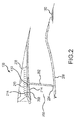
- Nacelle 100 for a gas turbine engine is illustrated according to various embodiments.
- Nacelle 100 may comprise an inlet 110, a fan cowl 120, and a thrust reverser 130.
- Nacelle 100 may be coupled to a pylon 140 (only part of which is shown), which may mount the nacelle 100 to an aircraft wing or aircraft body.
- Nacelle 100 may further comprise an exhaust nozzle 150.
- the thrust reverser 130 may comprise a cascade-type thrust reverser, in which bypass air is directed through a cascade in order to apply a reverse thrust to an aircraft, such as during landing.
- the nacelle 100 may be disposed about a centerline 105, which may also be the axis of rotation of an engine located within the nacelle 100.
- a translating sleeve 206 is coupled to a blocker door 200 via hinges, such as hinge lugs 408A and 408B.
- Blocker door 200 includes an airflow side 214 and a non-airflow side 216. Airflow through thrust reverser 130 (i.e., flowing through a bypass air duct 250) contacts airflow side 214 and does not contact non-airflow side 216.
- Blocker door 200 further includes a drag link housing 410 that is configured to be coupled to a drag link 202. Drag link 202 may be coupled to a fixed structure 208 via a drag link fitting.
- thrust reverser 130 may include a plurality of blocker doors and cascades positioned circumferentially about centerline 105, as is known by those of skill in this art.
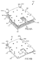
- blocker door 200 which may include a skeletal, structural frame 400 and a front sheet 402.
- structural frame 400 may comprise aluminum or an aluminum alloy and/or other metals and in various embodiments may be formed using die casting, machining, additive manufacturing or the like.
- Structural frame 400 may be temperature resistant and structurally stiff such that it retains its shape in response to being subjected to relatively high temperatures and forces. Structural frame 400 may by itself have the necessary load carrying capability to resist all the loads that the blocker door 200 is expected to experience, without relying upon any of the strength gained through combining its structure with front sheet 402 or other components.
- Structural frame 400 is ideally made as a unitary metallic component, and die casting may be an especially effective manufacturing method.
- Structural frame 400 constitutes a plurality of relatively thin, intersecting, and interconnected rib members. At least one rib member 470 may extend generally continuously along and generally adjacent to the top of blocker door 200 from one side to the other, and at least another rib member 472 may extend generally continuously along and generally adjacent to the bottom of blocker door 200 from one side to the other. Also, at least two rib members 474 and 476 may extend generally continuously from the top of blocker door 200 to the bottom of blocker door 200, interconnecting the top rib member 470 and the bottom rib member 472.
- Structural frame 400 may include a plurality of tabs 406 including, for example, tab 406A and tab 406B.
- Front sheet 402 may be positioned on airflow side 214 of structural frame 400 and may be coupled to structural frame 400 at a plurality of coupling locations 404 including coupling location 404A and coupling location 404B.
- one or more coupling locations 404 may be positioned at tabs 406.
- structural frame 400 may be coupled to front sheet 402 using rivets through coupling locations 404 and tabs 406.
- the rivets may comprise aluminum.
- Structural frame 400 may define a plurality of areas between its ribs including a top area 412, a middle area 414, a lower left area 416 and a lower right area 418. Ribs of structural frame 400 may separate and enclose or define each area 412, 414, 416 and 418. With brief reference now to FIGS. 4 and 7 , a core assembly 601 may be positioned substantially inside of top area 412, middle area 414, lower left area 416 and lower right area 418.
- front sheet 402 may be perforated with perforations 460 (only a few of which are illustrated in FIG. 4 ).
- the perforations 460 of front sheet 402 may allow sound to pass through front sheet 402 to the chambers in the core assembly 601, to attenuate sound in a known fashion.
- front sheet 402 may constitute a fiber reinforced composite, possibly a laminar composite, which could be formed in a closed die molding type of process or through other processes.
- Front sheet 402 may also be made from sheet metals or other materials.
- the plurality of perforations 460 may be pressed into front sheet 402, or could be formed through other methods.
- structural frame 400 may define or include hinge lugs 408A and 408B which may be integrally formed with the rib members or separately attached.
- Blocker door 200 may be coupled to translating sleeve 206 via hinge joints using hinge lugs 408A and 408B, allowing blocker door 200 to remain coupled to translating sleeve 206 and rotate with respect to translating sleeve 206.
- Structural frame 400 may also define drag link housing 410 which may be integrally formed with the rib members or separately attached. Drag link housing 410 may help locate and attach drag link 202 to structural frame 400 with a hinge joint.
- hinge lugs 408A and 408B, drag link housing 410 and structural frame 400 may all be formed by casting, such as investment casting or die casting using a single die.
- core assembly 601 may include acoustic cores including a top core 500, a middle core 502, a bottom left core 504 and a bottom right core 506.
- Each of the acoustic cores may be capable of helping to form resonating chambers used in attenuating sound.
- each of the acoustic cores may be manufactured via injection molding, die casting, machining, additive manufacturing or the like and may be constructed from a plastic material such as a thermoplastic or thermoset.
- each of the acoustic cores may comprise polyether ether ketone (PEEK), polyphenylene sulfide (PPS) or the like.
- PEEK polyether ether ketone
- PPS polyphenylene sulfide
- each of the acoustic cores may be manufactured using a single injection mold or may be manufactured using separate injection molds for one or more of the acoustic cores.
- middle core 502, bottom left core 504, and bottom right core 506 may define an opening 510.
- opening 510 may align with drag link housing 410 such that drag link housing 410 may extend through opening 510.
- core assembly 601 may include a backskin 600 that is mechanically coupled to the acoustic cores or optionally unitarily formed therewith. If uniformly formed, backskin 600 and several or all of the cores 500, 502, 504, 506 could be injection molded or die cast. If separately formed and then mechanically attached, backskin 600 may also be made by injection molding, or by machining, casting (such as investment casting or die casting), additive manufacturing or the like. Backskin 600 may be formed from a laminar fiber reinforced composite material such as carbon, fiberglass or a para-aramid synthetic fiber (also known as KevlarTM, available from DuPont of Wilmington, DE) bonded using an epoxy or other thermoset or a thermoplastic.
- laminar fiber reinforced composite material such as carbon, fiberglass or a para-aramid synthetic fiber (also known as KevlarTM, available from DuPont of Wilmington, DE) bonded using an epoxy or other thermoset or a thermoplastic.
- backskin 600 might advantageously be formed from a laminar composite in a closed-die type forming process.
- backskin 600 may or may not comprise the same material as the acoustic cores.
- Backskin 600 may define an opening 610 that aligns with opening 510 in response to backskin 600 being coupled to the acoustic cores.
- Backskin 600 may also include a plurality of openings 602, including opening 602A and opening 602B, and a plurality of washer surfaces 604, including washer surface 604A and washer surface 604B. Washer surface 604A may extend from backskin 600 towards non-airflow side 216 and may surround and define opening 602A.
- the acoustic cores may include a plurality of heat stakes 650, including heat stake 650A and heat stake 650B.
- the plurality of heat stakes 650 may extend away from the acoustic cores towards non-airflow side 216.
- the plurality of heat stakes 650 may extend through the plurality of openings 602.
- the plurality of heat stakes 650 may then be heated until the plurality of heat stakes 650 and the plurality of washer surfaces 604 soften and join together.
- the acoustic cores and backskin 600 may be coupled by welding, as the plurality of heat stakes 650 are welded to the plurality of openings 602 and/or the plurality of washer surfaces 604.
- core assembly 601 may be coupled to structural frame 400.
- drag link housing 410 may extend through opening 610.
- Core assembly 601 may be coupled to structural frame 400 at a plurality of coupling locations 700A including coupling location 700A and coupling location 700B.
- structural frame 400 and core assembly 601 may be coupled using rivets, such as aluminum rivets, in the plurality of coupling locations 700.
- core assembly 601 may be positioned on non-airflow side 216 of structural frame 400.
- blocker door 200 may include a spring 800 (part of the hinge connection between blocker door 200 and drag link 202) coupled to core assembly 601, structural frame 400, backskin 600 and/or front sheet 402 at a plurality of coupling locations 802, including a coupling location 802A, a coupling location 802B, and a coupling location 802C.
- spring 800 may be coupled to backskin 600 and structural frame 400 and not to core assembly 601 and/or front sheet 402.
- Selection of components to which spring 800 is coupled is determined based on a trade-off between a desire to have more fasteners securing front sheet 402 to structural frame 400 (when spring 800 is coupled to all components) versus a desire to have fewer fasteners on the airflow side of blocker door 200 (thus reducing drag when blocker door 200 is stowed).
- spring 800 may be coupled to core assembly 601. structural frame 400 and/or front sheet 402 using a combination of a threaded fastener consisting of a threaded pin and a threaded collar (such as a Hi-LokTM, available from Lisi Aerospace of Paris, France) at each of the plurality of coupling locations 802 such that the threaded fasteners extend from non-airflow side 216 of spring 800 through core assembly 601, structural frame 400 and through front sheet 402.
- spring 800 may be formed by machining, forming, casting (such as investment casting or die casting) or additive manufacturing and in various embodiments may include aluminum.
- Blocker door 200 provides advantages over traditional blocker doors.
- core assembly 601 is less expensive to form than a traditional core assembly as each of the core parts can be manufactured using injection molding or additive manufacturing.
- Front sheet 402 and backskin 600 may be cut from metal sheet stock, formed of composites in a closed die process, or injection molded.
- hinge lugs and drag link housings are manufactured separately from the other components of the blocker doors and are later coupled to the blocker doors.
- hinge lugs 408A and 408B and drag link housing 410 are formed as part of structural frame 400, the additional time consuming and expensive step of separately making these pieces and coupling each of them to the proper place on the blocker door can be eliminated.
- references to "one embodiment”, “an embodiment”, “various embodiments”, etc. indicate that the embodiment described may include a particular feature, structure, or characteristic, but every embodiment may not necessarily include the particular feature, structure, or characteristic. Moreover, such phrases are not necessarily referring to the same embodiment. Further, when a particular feature, structure, or characteristic is described in connection with an embodiment, it is submitted that it is within the knowledge of one skilled in the art to affect such feature, structure, or characteristic in connection with other embodiments whether or not explicitly described. After reading the description, it will be apparent to one skilled in the relevant art(s) how to implement the disclosure in alternative embodiments.
Landscapes
- Engineering & Computer Science (AREA)
- Chemical & Material Sciences (AREA)
- Combustion & Propulsion (AREA)
- Mechanical Engineering (AREA)
- General Engineering & Computer Science (AREA)
- Injection Moulding Of Plastics Or The Like (AREA)
Applications Claiming Priority (1)
| Application Number | Priority Date | Filing Date | Title |
|---|---|---|---|
| US14/704,889 US9845769B2 (en) | 2015-05-05 | 2015-05-05 | Plastic core blocker door |
Publications (1)
| Publication Number | Publication Date |
|---|---|
| EP3128163A1 true EP3128163A1 (fr) | 2017-02-08 |
Family
ID=55968914
Family Applications (1)
| Application Number | Title | Priority Date | Filing Date |
|---|---|---|---|
| EP16168343.8A Withdrawn EP3128163A1 (fr) | 2015-05-05 | 2016-05-04 | Porte de blocage central en plastique |
Country Status (2)
| Country | Link |
|---|---|
| US (1) | US9845769B2 (fr) |
| EP (1) | EP3128163A1 (fr) |
Cited By (6)
| Publication number | Priority date | Publication date | Assignee | Title |
|---|---|---|---|---|
| EP3290679A1 (fr) * | 2016-08-29 | 2018-03-07 | The Boeing Company | Ensemble porte de blocage ayant une porte de blocage thermoplastique destinée à être utilisée dans un moteur à turbine |
| EP3361082A1 (fr) * | 2017-02-10 | 2018-08-15 | Rohr, Inc. | Éléments de raidissement de volet d'inverseur |
| US10406729B2 (en) | 2016-08-29 | 2019-09-10 | The Boeing Company | Compression molding assembly and methods for molding a thermoplastic blocker door |
| EP3626958A1 (fr) * | 2018-09-24 | 2020-03-25 | Rohr, Inc. | Porte de blocage acoustique thermoplastique |
| WO2023247893A1 (fr) | 2022-06-22 | 2023-12-28 | Safran Nacelles | Volet de blocage d'un inverseur de poussée d'aéronef |
| EP4397850A1 (fr) * | 2023-01-03 | 2024-07-10 | Rohr, Inc. | Fabrication de porte de blocage d'inverseur de poussée à l'aide d'un surmoulage |
Families Citing this family (6)
| Publication number | Priority date | Publication date | Assignee | Title |
|---|---|---|---|---|
| US10431201B1 (en) | 2018-03-20 | 2019-10-01 | International Business Machines Corporation | Analyzing messages with typographic errors due to phonemic spellings using text-to-speech and speech-to-text algorithms |
| FR3089567B1 (fr) * | 2018-12-07 | 2020-11-20 | Safran Nacelles | Inverseur de poussée muni d’un volet d’inversion de poussée allégé |
| FR3095677B1 (fr) * | 2019-05-03 | 2021-04-09 | Safran Aircraft Engines | Grille d’inverseur de poussée incluant un traitement acoustique |
| US11680542B2 (en) * | 2020-02-03 | 2023-06-20 | Rohr, Inc. | Thrust reverser door and method for making same |
| FR3127433A1 (fr) * | 2021-09-29 | 2023-03-31 | Airbus Operations (S.A.S.) | Procédé de fabrication d’une porte d’un système d’inversion de poussée, porte de système d’inversion de poussée ainsi obtenue et ensemble de propulsion d’aéronef comprenant plusieurs desdites portes |
| US12104556B1 (en) * | 2023-09-11 | 2024-10-01 | Rohr, Inc. | Blocker door retention assembly for an aircraft propulsion system thrust reverser |
Citations (5)
| Publication number | Priority date | Publication date | Assignee | Title |
|---|---|---|---|---|
| US4278220A (en) * | 1979-03-30 | 1981-07-14 | The United States Of America As Represented By The Administrator Of The National Aeronautics And Space Administration | Thrust reverser for a long duct fan engine |
| US4564160A (en) * | 1982-09-29 | 1986-01-14 | The Boeing Company | Thrust reverser blocker door assembly |
| EP0799376A1 (fr) * | 1994-12-22 | 1997-10-08 | United Technologies Corporation | Inverseur de poussee compact |
| US5927647A (en) * | 1997-09-24 | 1999-07-27 | Rohr, Inc. | Blocker door frame pressure structure for translating cowl of cascade thrust reverser for aircraft jet engine |
| US20150027629A1 (en) * | 2013-07-29 | 2015-01-29 | The Boeing Company | Septumization of Honeycomb Sandwiches |
Family Cites Families (25)
| Publication number | Priority date | Publication date | Assignee | Title |
|---|---|---|---|---|
| FR2348371A1 (fr) * | 1976-04-14 | 1977-11-10 | Astech | Inverseur de poussee pour moteur a reaction |
| FR2506843B1 (fr) * | 1981-05-29 | 1987-04-24 | Hurel Dubois Avions | Dispositif d'inversion de poussee pour turboreacteur d'avion |
| US4852805A (en) | 1983-12-30 | 1989-08-01 | The Boeing Company | Hybrid thrust reverser cascade basket and method |
| US4826106A (en) | 1987-02-18 | 1989-05-02 | Grumman Aerospace Corporation | Advanced composite aircraft cowl |
| FR2611233B1 (fr) * | 1987-02-19 | 1991-05-10 | Hurel Dubois Avions | Groupe moto-propulseur d'avion du type a ventilateur capote equipe d'un inverseur de poussee a portes |
| GB9014381D0 (en) | 1990-06-28 | 1990-08-22 | Short Brothers Plc | A composite structural component |
| US5230213A (en) * | 1991-06-12 | 1993-07-27 | Rohr, Inc. | Aircraft turbine engine thrust reverser |
| US5476237A (en) | 1993-06-18 | 1995-12-19 | Northrop Grumman Corporation | Syntactic film for thrust reverser blocker doors |
| US5806302A (en) | 1996-09-24 | 1998-09-15 | Rohr, Inc. | Variable fan exhaust area nozzle for aircraft gas turbine engine with thrust reverser |
| EP0852290A1 (fr) * | 1996-12-19 | 1998-07-08 | SOCIETE DE CONSTRUCTION DES AVIONS HUREL-DUBOIS (société anonyme) | Inverseur de poussée de turboréacteur à double flux avec grand taux de dilution |
| US6173807B1 (en) | 1998-04-13 | 2001-01-16 | The Boeing Company | Engine nacelle acoustic panel with integral wedge fairings and an integral forward ring |
| FR2767560B1 (fr) | 1997-08-19 | 1999-11-12 | Aerospatiale | Ensemble reducteur de bruit pour turboreacteur d'aeronef |
| GB9802597D0 (en) | 1998-02-07 | 1998-04-01 | Hurel Dubois Uk Ltd | Panels and structures |
| US6170254B1 (en) | 1998-12-18 | 2001-01-09 | Rohr, Inc. | Translating sleeve for cascade type thrust reversing system for fan gas turbine engine for an aircraft |
| FR2804474B1 (fr) * | 2000-01-27 | 2002-06-28 | Hispano Suiza Sa | Inverseur de poussee a grilles aubagees de deviation a structure arriere fixe |
| US20080083210A1 (en) | 2006-10-04 | 2008-04-10 | Spirit Aerosystems, Inc | Monolithic thrust reverser components |
| FR2926605B1 (fr) * | 2008-01-18 | 2012-08-31 | Aircelle Sa | Structure 12 heures pour inverseur de poussee notamment a grilles |
| FR2958978B1 (fr) * | 2010-04-20 | 2014-04-18 | Aircelle Sa | Agencement de bielles de volets d'inversion de poussee sur la structure interne fixe d'une nacelle de turboreacteur |
| FR2963949A1 (fr) * | 2010-08-18 | 2012-02-24 | Aircelle Sa | Poutre notamment pour inverseur de poussee a grilles |
| WO2013003411A1 (fr) * | 2011-06-29 | 2013-01-03 | Zephyros, Inc. | Panneau d'insonorisation et procédé d'assemblage associé |
| US9249681B2 (en) * | 2012-01-31 | 2016-02-02 | United Technologies Corporation | Fan case rub system |
| US8904751B2 (en) | 2012-04-30 | 2014-12-09 | Middle River Aircraft Systems | Thrust reverser assembly and method of operation |
| US10006405B2 (en) | 2012-11-30 | 2018-06-26 | General Electric Company | Thrust reverser system with translating-rotating blocker doors and method of operation |
| EP3019727A4 (fr) | 2013-07-09 | 2017-05-10 | United Technologies Corporation | Élément de turbine polymère métallisé |
| CA2919124A1 (fr) | 2013-07-30 | 2015-02-05 | General Electric Company | Systeme inverseur de poussee a ensemble charniere a translation-rotation |
-
2015
- 2015-05-05 US US14/704,889 patent/US9845769B2/en active Active
-
2016
- 2016-05-04 EP EP16168343.8A patent/EP3128163A1/fr not_active Withdrawn
Patent Citations (5)
| Publication number | Priority date | Publication date | Assignee | Title |
|---|---|---|---|---|
| US4278220A (en) * | 1979-03-30 | 1981-07-14 | The United States Of America As Represented By The Administrator Of The National Aeronautics And Space Administration | Thrust reverser for a long duct fan engine |
| US4564160A (en) * | 1982-09-29 | 1986-01-14 | The Boeing Company | Thrust reverser blocker door assembly |
| EP0799376A1 (fr) * | 1994-12-22 | 1997-10-08 | United Technologies Corporation | Inverseur de poussee compact |
| US5927647A (en) * | 1997-09-24 | 1999-07-27 | Rohr, Inc. | Blocker door frame pressure structure for translating cowl of cascade thrust reverser for aircraft jet engine |
| US20150027629A1 (en) * | 2013-07-29 | 2015-01-29 | The Boeing Company | Septumization of Honeycomb Sandwiches |
Cited By (11)
| Publication number | Priority date | Publication date | Assignee | Title |
|---|---|---|---|---|
| EP3290679A1 (fr) * | 2016-08-29 | 2018-03-07 | The Boeing Company | Ensemble porte de blocage ayant une porte de blocage thermoplastique destinée à être utilisée dans un moteur à turbine |
| US10406729B2 (en) | 2016-08-29 | 2019-09-10 | The Boeing Company | Compression molding assembly and methods for molding a thermoplastic blocker door |
| US10794326B2 (en) | 2016-08-29 | 2020-10-06 | The Boeing Company | Blocker door assembly having a thermoplastic blocker door for use in a turbine engine |
| US11840986B2 (en) | 2016-08-29 | 2023-12-12 | The Boeing Company | Blocker door assembly having a thermoplastic blocker door for use in a turbine engine |
| EP3361082A1 (fr) * | 2017-02-10 | 2018-08-15 | Rohr, Inc. | Éléments de raidissement de volet d'inverseur |
| US10378480B2 (en) | 2017-02-10 | 2019-08-13 | Rohr, Inc | Blocker door stiffening features |
| EP3626958A1 (fr) * | 2018-09-24 | 2020-03-25 | Rohr, Inc. | Porte de blocage acoustique thermoplastique |
| US11261825B2 (en) | 2018-09-24 | 2022-03-01 | Rohr, Inc. | Thermoplastic acoustic blocker door |
| WO2023247893A1 (fr) | 2022-06-22 | 2023-12-28 | Safran Nacelles | Volet de blocage d'un inverseur de poussée d'aéronef |
| FR3137133A1 (fr) | 2022-06-22 | 2023-12-29 | Safran Nacelles | Volet de blocage d’un inverseur de poussée d’aéronef |
| EP4397850A1 (fr) * | 2023-01-03 | 2024-07-10 | Rohr, Inc. | Fabrication de porte de blocage d'inverseur de poussée à l'aide d'un surmoulage |
Also Published As
| Publication number | Publication date |
|---|---|
| US20160326985A1 (en) | 2016-11-10 |
| US9845769B2 (en) | 2017-12-19 |
Similar Documents
| Publication | Publication Date | Title |
|---|---|---|
| EP3128163A1 (fr) | Porte de blocage central en plastique | |
| EP3626958B1 (fr) | Porte de blocage acoustique thermoplastique | |
| EP0894715B1 (fr) | Panneau extérieur d'un capot de nacelle d'un moteur avec des carénages d'un rail de guidage integrés et procédé pour sa fabrication | |
| US4826106A (en) | Advanced composite aircraft cowl | |
| US9835112B2 (en) | Thrust reverser cascade | |
| US20090313969A1 (en) | Thrust Reverser for a Turbofan Gas Turbine Engine | |
| US9714612B2 (en) | Drag link fitting and vent combination | |
| US10738738B2 (en) | Nacelle with bifurcation extension and integral structural reinforcement | |
| EP3594127B1 (fr) | Système de régulation de flux laminaire actif comportant un panneau composite | |
| US9714627B2 (en) | Mounting of aircraft propulsion system outer sleeve and inner structure to pylon with distinct hinges | |
| EP3584434B1 (fr) | Cascade d'inverseur de poussée et son procédé de fabrication | |
| CN112189089B (zh) | 用于飞行器喷气发动机短舱的声学衰减板 | |
| US10253727B2 (en) | Backside acoustic treatment of nacelle structural fittings | |
| CN110654527B (zh) | 用于推力反向器的吸声板 | |
| US9834313B2 (en) | Front frame for a cascade thrust reverser structure | |
| US11448161B2 (en) | Acoustic fairing | |
| EP4108443A1 (fr) | Panneau acoustique et son procédé de formage | |
| US20220195961A1 (en) | Thrust reverser cascade and method of manufacture | |
| EP2865878A1 (fr) | Broche à cardan pour système de propulsion par réaction | |
| EP3578790B1 (fr) | Ensemble en cascade pour un inverseur de poussée de turboréacteur | |
| US20200392923A1 (en) | Thrust reverser cascade and method of manufacture | |
| US20220042454A1 (en) | Nacelle air intake with an acoustic panel | |
| US20240125283A1 (en) | Assembly Comprising a Nacelle Panel and a Member Forming a Ball |
Legal Events
| Date | Code | Title | Description |
|---|---|---|---|
| PUAI | Public reference made under article 153(3) epc to a published international application that has entered the european phase |
Free format text: ORIGINAL CODE: 0009012 |
|
| STAA | Information on the status of an ep patent application or granted ep patent |
Free format text: STATUS: THE APPLICATION HAS BEEN PUBLISHED |
|
| AK | Designated contracting states |
Kind code of ref document: A1 Designated state(s): AL AT BE BG CH CY CZ DE DK EE ES FI FR GB GR HR HU IE IS IT LI LT LU LV MC MK MT NL NO PL PT RO RS SE SI SK SM TR |
|
| AX | Request for extension of the european patent |
Extension state: BA ME |
|
| STAA | Information on the status of an ep patent application or granted ep patent |
Free format text: STATUS: REQUEST FOR EXAMINATION WAS MADE |
|
| 17P | Request for examination filed |
Effective date: 20170802 |
|
| RBV | Designated contracting states (corrected) |
Designated state(s): AL AT BE BG CH CY CZ DE DK EE ES FI FR GB GR HR HU IE IS IT LI LT LU LV MC MK MT NL NO PL PT RO RS SE SI SK SM TR |
|
| STAA | Information on the status of an ep patent application or granted ep patent |
Free format text: STATUS: THE APPLICATION IS DEEMED TO BE WITHDRAWN |
|
| 18D | Application deemed to be withdrawn |
Effective date: 20181201 |