EP3128157A1 - Drive force control system, and vehicle provided with drive force control system - Google Patents
Drive force control system, and vehicle provided with drive force control system Download PDFInfo
- Publication number
- EP3128157A1 EP3128157A1 EP15773173.8A EP15773173A EP3128157A1 EP 3128157 A1 EP3128157 A1 EP 3128157A1 EP 15773173 A EP15773173 A EP 15773173A EP 3128157 A1 EP3128157 A1 EP 3128157A1
- Authority
- EP
- European Patent Office
- Prior art keywords
- centrifugal
- clutch
- upstream
- path
- rotation speed
- Prior art date
- Legal status (The legal status is an assumption and is not a legal conclusion. Google has not performed a legal analysis and makes no representation as to the accuracy of the status listed.)
- Granted
Links
Images


Classifications
-
- F—MECHANICAL ENGINEERING; LIGHTING; HEATING; WEAPONS; BLASTING
- F02—COMBUSTION ENGINES; HOT-GAS OR COMBUSTION-PRODUCT ENGINE PLANTS
- F02D—CONTROLLING COMBUSTION ENGINES
- F02D29/00—Controlling engines, such controlling being peculiar to the devices driven thereby, the devices being other than parts or accessories essential to engine operation, e.g. controlling of engines by signals external thereto
- F02D29/02—Controlling engines, such controlling being peculiar to the devices driven thereby, the devices being other than parts or accessories essential to engine operation, e.g. controlling of engines by signals external thereto peculiar to engines driving vehicles; peculiar to engines driving variable pitch propellers
-
- B—PERFORMING OPERATIONS; TRANSPORTING
- B60—VEHICLES IN GENERAL
- B60K—ARRANGEMENT OR MOUNTING OF PROPULSION UNITS OR OF TRANSMISSIONS IN VEHICLES; ARRANGEMENT OR MOUNTING OF PLURAL DIVERSE PRIME-MOVERS IN VEHICLES; AUXILIARY DRIVES FOR VEHICLES; INSTRUMENTATION OR DASHBOARDS FOR VEHICLES; ARRANGEMENTS IN CONNECTION WITH COOLING, AIR INTAKE, GAS EXHAUST OR FUEL SUPPLY OF PROPULSION UNITS IN VEHICLES
- B60K28/00—Safety devices for propulsion-unit control, specially adapted for, or arranged in, vehicles, e.g. preventing fuel supply or ignition in the event of potentially dangerous conditions
- B60K28/10—Safety devices for propulsion-unit control, specially adapted for, or arranged in, vehicles, e.g. preventing fuel supply or ignition in the event of potentially dangerous conditions responsive to conditions relating to the vehicle
- B60K28/16—Safety devices for propulsion-unit control, specially adapted for, or arranged in, vehicles, e.g. preventing fuel supply or ignition in the event of potentially dangerous conditions responsive to conditions relating to the vehicle responsive to, or preventing, spinning or skidding of wheels
-
- B—PERFORMING OPERATIONS; TRANSPORTING
- B60—VEHICLES IN GENERAL
- B60W—CONJOINT CONTROL OF VEHICLE SUB-UNITS OF DIFFERENT TYPE OR DIFFERENT FUNCTION; CONTROL SYSTEMS SPECIALLY ADAPTED FOR HYBRID VEHICLES; ROAD VEHICLE DRIVE CONTROL SYSTEMS FOR PURPOSES NOT RELATED TO THE CONTROL OF A PARTICULAR SUB-UNIT
- B60W10/00—Conjoint control of vehicle sub-units of different type or different function
- B60W10/04—Conjoint control of vehicle sub-units of different type or different function including control of propulsion units
- B60W10/06—Conjoint control of vehicle sub-units of different type or different function including control of propulsion units including control of combustion engines
-
- B—PERFORMING OPERATIONS; TRANSPORTING
- B60—VEHICLES IN GENERAL
- B60W—CONJOINT CONTROL OF VEHICLE SUB-UNITS OF DIFFERENT TYPE OR DIFFERENT FUNCTION; CONTROL SYSTEMS SPECIALLY ADAPTED FOR HYBRID VEHICLES; ROAD VEHICLE DRIVE CONTROL SYSTEMS FOR PURPOSES NOT RELATED TO THE CONTROL OF A PARTICULAR SUB-UNIT
- B60W30/00—Purposes of road vehicle drive control systems not related to the control of a particular sub-unit, e.g. of systems using conjoint control of vehicle sub-units
- B60W30/18—Propelling the vehicle
- B60W30/18172—Preventing, or responsive to skidding of wheels
-
- F—MECHANICAL ENGINEERING; LIGHTING; HEATING; WEAPONS; BLASTING
- F02—COMBUSTION ENGINES; HOT-GAS OR COMBUSTION-PRODUCT ENGINE PLANTS
- F02D—CONTROLLING COMBUSTION ENGINES
- F02D41/00—Electrical control of supply of combustible mixture or its constituents
- F02D41/02—Circuit arrangements for generating control signals
- F02D41/0205—Circuit arrangements for generating control signals using an auxiliary engine speed control
-
- F—MECHANICAL ENGINEERING; LIGHTING; HEATING; WEAPONS; BLASTING
- F02—COMBUSTION ENGINES; HOT-GAS OR COMBUSTION-PRODUCT ENGINE PLANTS
- F02D—CONTROLLING COMBUSTION ENGINES
- F02D41/00—Electrical control of supply of combustible mixture or its constituents
- F02D41/02—Circuit arrangements for generating control signals
- F02D41/021—Introducing corrections for particular conditions exterior to the engine
- F02D41/0215—Introducing corrections for particular conditions exterior to the engine in relation with elements of the transmission
- F02D41/022—Introducing corrections for particular conditions exterior to the engine in relation with elements of the transmission in relation with the clutch status
-
- F—MECHANICAL ENGINEERING; LIGHTING; HEATING; WEAPONS; BLASTING
- F16—ENGINEERING ELEMENTS AND UNITS; GENERAL MEASURES FOR PRODUCING AND MAINTAINING EFFECTIVE FUNCTIONING OF MACHINES OR INSTALLATIONS; THERMAL INSULATION IN GENERAL
- F16D—COUPLINGS FOR TRANSMITTING ROTATION; CLUTCHES; BRAKES
- F16D43/00—Automatic clutches
- F16D43/02—Automatic clutches actuated entirely mechanically
- F16D43/04—Automatic clutches actuated entirely mechanically controlled by angular speed
- F16D43/14—Automatic clutches actuated entirely mechanically controlled by angular speed with centrifugal masses actuating the clutching members directly in a direction which has at least a radial component; with centrifugal masses themselves being the clutching members
- F16D43/18—Automatic clutches actuated entirely mechanically controlled by angular speed with centrifugal masses actuating the clutching members directly in a direction which has at least a radial component; with centrifugal masses themselves being the clutching members with friction clutching members
-
- B—PERFORMING OPERATIONS; TRANSPORTING
- B60—VEHICLES IN GENERAL
- B60W—CONJOINT CONTROL OF VEHICLE SUB-UNITS OF DIFFERENT TYPE OR DIFFERENT FUNCTION; CONTROL SYSTEMS SPECIALLY ADAPTED FOR HYBRID VEHICLES; ROAD VEHICLE DRIVE CONTROL SYSTEMS FOR PURPOSES NOT RELATED TO THE CONTROL OF A PARTICULAR SUB-UNIT
- B60W2300/00—Indexing codes relating to the type of vehicle
- B60W2300/36—Cycles; Motorcycles; Scooters
-
- B—PERFORMING OPERATIONS; TRANSPORTING
- B60—VEHICLES IN GENERAL
- B60W—CONJOINT CONTROL OF VEHICLE SUB-UNITS OF DIFFERENT TYPE OR DIFFERENT FUNCTION; CONTROL SYSTEMS SPECIALLY ADAPTED FOR HYBRID VEHICLES; ROAD VEHICLE DRIVE CONTROL SYSTEMS FOR PURPOSES NOT RELATED TO THE CONTROL OF A PARTICULAR SUB-UNIT
- B60W2510/00—Input parameters relating to a particular sub-units
- B60W2510/02—Clutches
- B60W2510/0208—Clutch engagement state, e.g. engaged or disengaged
-
- B—PERFORMING OPERATIONS; TRANSPORTING
- B60—VEHICLES IN GENERAL
- B60W—CONJOINT CONTROL OF VEHICLE SUB-UNITS OF DIFFERENT TYPE OR DIFFERENT FUNCTION; CONTROL SYSTEMS SPECIALLY ADAPTED FOR HYBRID VEHICLES; ROAD VEHICLE DRIVE CONTROL SYSTEMS FOR PURPOSES NOT RELATED TO THE CONTROL OF A PARTICULAR SUB-UNIT
- B60W2510/00—Input parameters relating to a particular sub-units
- B60W2510/02—Clutches
- B60W2510/0241—Clutch slip, i.e. difference between input and output speeds
-
- B—PERFORMING OPERATIONS; TRANSPORTING
- B60—VEHICLES IN GENERAL
- B60W—CONJOINT CONTROL OF VEHICLE SUB-UNITS OF DIFFERENT TYPE OR DIFFERENT FUNCTION; CONTROL SYSTEMS SPECIALLY ADAPTED FOR HYBRID VEHICLES; ROAD VEHICLE DRIVE CONTROL SYSTEMS FOR PURPOSES NOT RELATED TO THE CONTROL OF A PARTICULAR SUB-UNIT
- B60W2510/00—Input parameters relating to a particular sub-units
- B60W2510/06—Combustion engines, Gas turbines
- B60W2510/0638—Engine speed
- B60W2510/0652—Speed change rate
-
- B—PERFORMING OPERATIONS; TRANSPORTING
- B60—VEHICLES IN GENERAL
- B60W—CONJOINT CONTROL OF VEHICLE SUB-UNITS OF DIFFERENT TYPE OR DIFFERENT FUNCTION; CONTROL SYSTEMS SPECIALLY ADAPTED FOR HYBRID VEHICLES; ROAD VEHICLE DRIVE CONTROL SYSTEMS FOR PURPOSES NOT RELATED TO THE CONTROL OF A PARTICULAR SUB-UNIT
- B60W2520/00—Input parameters relating to overall vehicle dynamics
- B60W2520/26—Wheel slip
- B60W2520/263—Slip values between front and rear axle
-
- B—PERFORMING OPERATIONS; TRANSPORTING
- B60—VEHICLES IN GENERAL
- B60W—CONJOINT CONTROL OF VEHICLE SUB-UNITS OF DIFFERENT TYPE OR DIFFERENT FUNCTION; CONTROL SYSTEMS SPECIALLY ADAPTED FOR HYBRID VEHICLES; ROAD VEHICLE DRIVE CONTROL SYSTEMS FOR PURPOSES NOT RELATED TO THE CONTROL OF A PARTICULAR SUB-UNIT
- B60W2520/00—Input parameters relating to overall vehicle dynamics
- B60W2520/28—Wheel speed
-
- B—PERFORMING OPERATIONS; TRANSPORTING
- B60—VEHICLES IN GENERAL
- B60W—CONJOINT CONTROL OF VEHICLE SUB-UNITS OF DIFFERENT TYPE OR DIFFERENT FUNCTION; CONTROL SYSTEMS SPECIALLY ADAPTED FOR HYBRID VEHICLES; ROAD VEHICLE DRIVE CONTROL SYSTEMS FOR PURPOSES NOT RELATED TO THE CONTROL OF A PARTICULAR SUB-UNIT
- B60W2710/00—Output or target parameters relating to a particular sub-units
- B60W2710/06—Combustion engines, Gas turbines
- B60W2710/0644—Engine speed
- B60W2710/0661—Speed change rate
-
- F—MECHANICAL ENGINEERING; LIGHTING; HEATING; WEAPONS; BLASTING
- F16—ENGINEERING ELEMENTS AND UNITS; GENERAL MEASURES FOR PRODUCING AND MAINTAINING EFFECTIVE FUNCTIONING OF MACHINES OR INSTALLATIONS; THERMAL INSULATION IN GENERAL
- F16D—COUPLINGS FOR TRANSMITTING ROTATION; CLUTCHES; BRAKES
- F16D43/00—Automatic clutches
- F16D43/02—Automatic clutches actuated entirely mechanically
- F16D43/04—Automatic clutches actuated entirely mechanically controlled by angular speed
- F16D43/14—Automatic clutches actuated entirely mechanically controlled by angular speed with centrifugal masses actuating the clutching members directly in a direction which has at least a radial component; with centrifugal masses themselves being the clutching members
- F16D2043/145—Automatic clutches actuated entirely mechanically controlled by angular speed with centrifugal masses actuating the clutching members directly in a direction which has at least a radial component; with centrifugal masses themselves being the clutching members the centrifugal masses being pivoting
Definitions
- the present invention relates to driving force control in a vehicle having a centrifugal clutch mounted therein.
- Patent Document 1 describes a motorcycle of a scooter type in which a centrifugal clutch is mounted.
- the motorscooter described in Patent Document 1 is equipped with a driving force control system.
- a driving force control system is a control system which adjusts slipping of the driving wheel.
- a centrifugal clutch is a clutch which engages based on a centrifugal force that occurs from rotation.
- Patent Document 1 Japanese Laid-Open Patent Publication No. 5-240076
- An objective of the present invention is to provide a driving force control system which can reduce the oddness felt by a rider, being suitable for a vehicle including a centrifugal clutch.
- a driving force control system is a driving force control system for use in a vehicle, the vehicle including an engine, a driving wheel to be driven by motive power from the engine, and a centrifugal clutch provided in a transmission path of motive power between the engine and the driving wheel, the driving force control system being to adjust slipping of the driving wheel in a state in which the driving wheel is slipping, wherein, the centrifugal clutch includes an upstream member mechanically connected to the engine to rotate, and a downstream member to be mechanically connected with or disengaged from the upstream member based on a centrifugal force occurring in accordance with rotation of the upstream member, and, with a centrifugal force which is in accordance with rotation of the upstream member, automatically turns ON or OFF transmission of motive power between an upstream-of-centrifugal-clutch path from the engine to the upstream member and a downstream-of-centrifugal-clutch path from the downstream member to the driving wheel; and the driving force control
- the reduction rate (A) under non-connection concerning the upstream-of-centrifugal-clutch path is a reduction rate in rotation speed of the upstream-of-centrifugal-clutch path when a difference exists between a rotation speed of the upstream member of the centrifugal clutch and a rotation speed of the downstream member of the centrifugal clutch.
- the reduction rate (B) under connection concerning the upstream-of-centrifugal-clutch path is a reduction rate in rotation speed of the upstream-of-centrifugal-clutch path when a rotation speed of the upstream member of the centrifugal clutch is equal to a rotation speed of the downstream member of the centrifugal clutch before a difference emerges between a rotation speed of the upstream member of the centrifugal clutch and a rotation speed of the downstream member of the centrifugal clutch.
- the driving force control system according to (P1-1) above may rely on at least one of a physical parameter concerning rotation of the upstream path and a physical parameter concerning rotation of the downstream path, in exerting control so that the reduction rate (A) under non-connection concerning the upstream-of-centrifugal-clutch path is smaller than the reduction rate (B) under connection.
- the driving force control system according to (P1-3) above may rely on the physical parameter concerning rotation of the upstream path and the physical parameter concerning rotation of the downstream path, in exerting control so that the reduction rate (A) under non-connection concerning the upstream-of-centrifugal-clutch path is smaller than the reduction rate (B) under connection.
- the driving force control system according to (P1-1) above may further rely on a rate of change in one of a physical parameter concerning rotation of the upstream path and a physical parameter concerning rotation of the downstream path, in exerting control so that the reduction rate (A) under non-connection concerning the upstream-of-centrifugal-clutch path is smaller than the reduction rate (B) under connection.
- the driving force control system according to (P1-1) above may include a control section to perform traction control in a state in which the driving wheel is slipping, wherein the control section may suspend the traction control or loosen the traction control in exerting control so that the reduction rate (A) under non-connection concerning the upstream-of-centrifugal-clutch path is smaller than the reduction rate (B) under connection.
- the driving force control system according to (P1-6) above may further comprise a first sensor to detect a rotation speed of the upstream path, and a second sensor to detect a rotation speed of the downstream path; and the control section may suspend the traction control or loosen the traction control when the rotation speed of the upstream path detected by the first sensor is less than, or equal to or smaller than, a preset first threshold and the rotation speed of the downstream path detected by the second sensor is less than, or equal to or smaller than, a preset second threshold.
- the control section of the driving force control system according to (P1-6) or (P1-7) above may perform the traction control by adjusting revolution of the engine in the upstream path.
- the first threshold may be set to a value higher than a rotation speed of the upstream path at which the upstream path and the downstream path having so far been connected is to be disconnected.
- the second threshold in the driving force control system according to (P1-7) above may be set to a value higher than a rotation speed of the downstream path at which the upstream path and the downstream path having so far been connected is to be disconnected.
- the first sensor may detect a value concerning revolution of the engine in the upstream path; and the second sensor may detect a value concerning rotation speed of the driving wheel in the downstream path.
- control section may begin the traction control or tighten the traction control when a value concerning an amount of change of revolution of the engine becomes equal to or greater than a preset third threshold.
- the control section of the driving force control system according to (P1-12) above may suspend the traction control or loosen the traction control when a value which is in accordance with a rate of change in one of the rotation speed of the upstream path detected by the first sensor and the rotation speed of the downstream path detected by the second sensor becomes less than, or equal to or smaller than, a preset third threshold.
- the driving force control system according to (P1-13) above may further comprise a third sensor to detect a vehicle speed of the vehicle, wherein, the second sensor may detect a value concerning rotation speed of the driving wheel in the downstream path; and the control section may suspend the traction control or loosen the traction control when a value which is in accordance with a rate of change in a slip velocity based on a rotation speed of the driving wheel detected by the second sensor and the vehicle speed detected by the third sensor becomes less than, or equal to or smaller than, the third threshold.
- the control section of the driving force control system according to (P1-14) above may suspend the traction control or loosen the traction control further when the vehicle speed detected by the third sensor becomes equal to or smaller than a fourth threshold.
- a vehicle according to the present invention comprises: the driving force control system of any of (P1-1) to (P1-15) above; the engine; the driving wheel; and the centrifugal clutch.
- the vehicle according to (P1-16) above may further comprise a non-driving wheel.
- a driving force control system is a driving force control system for use in a vehicle, the vehicle including an engine, a driving wheel to be driven by motive power from the engine, and a centrifugal clutch provided in a transmission path of motive power between the engine and the driving wheel, the driving force control system being to adjust slipping of the driving wheel in a state in which the driving wheel is slipping, wherein, the centrifugal clutch includes an upstream member mechanically connected to the engine to rotate, and a downstream member to be mechanically connected with or disengaged from the upstream member based on a centrifugal force occurring in accordance with rotation of the upstream member, and, with a centrifugal force which is in accordance with rotation of the upstream member, automatically turns ON or OFF transmission of motive power between an upstream-of-centrifugal-clutch path from the engine to the upstream member and a downstream-of-centrifugal-clutch path from the downstream member to the driving wheel.
- the driving force control system exerts control to suppress disengagement of the centrifugal clutch in accordance with at least one of a physical parameter concerning rotation of the upstream-of-centrifugal-clutch path and a physical parameter concerning rotation of the downstream-of-centrifugal-clutch path.
- the driving force control system according to (P2-1) above may, in a state in which the driving wheel is slipping, rely on the physical parameter concerning rotation of the upstream-of-centrifugal-clutch path and the physical parameter concerning rotation of the downstream-of-centrifugal-clutch path in exerting control to suppress disengagement of the centrifugal clutch.
- the driving force control system according to (P2-1) above may, in a state in which the driving wheel is slipping, rely on the physical parameter concerning rotation of the upstream-of-centrifugal-clutch path in exerting control to suppress disengagement of the centrifugal clutch.
- the driving force control system according to (P2-1) above may, in a state in which the driving wheel is slipping, rely on the physical parameter concerning rotation of the downstream-of-centrifugal-clutch path in exerting control to suppress disengagement of the centrifugal clutch.
- a control threshold ⁇ may be provided for the physical parameter concerning rotation of the upstream-of-centrifugal-clutch path and a control threshold ⁇ may be provided for the physical parameter concerning rotation of the downstream-of-centrifugal-clutch path, and the driving force control system may exert control to suppress disengagement of the centrifugal clutch when the physical parameter concerning rotation of the upstream-of-centrifugal-clutch path is less than, or equal to or smaller than, the control threshold ⁇ and the physical parameter concerning rotation of the downstream-of-centrifugal-clutch path is less than, or equal to or smaller than, the control threshold ⁇ .
- the physical parameter concerning rotation of the upstream-of-centrifugal-clutch path may be rotation speed or torque.
- the driving force control system according to (P2-1) above may include a control section to perform traction control of, in a state in which the driving wheel is slipping, controlling motive power of the engine to adjust slipping of the driving wheel, wherein the control section may suspend the traction control or loosen the traction control as the control to suppress disengagement of the centrifugal clutch.
- the driving force control system may further comprise a first sensor to detect the physical parameter concerning rotation of the upstream-of-centrifugal-clutch path and a second sensor to detect the physical parameter concerning rotation of the downstream-of-centrifugal-clutch path, wherein the control section may suspend the traction control or loosen the traction control when the physical parameter concerning rotation of the upstream-of-centrifugal-clutch path detected by the first sensor is less than, or equal to or smaller than, a preset control threshold ⁇ and a rotation speed of the physical parameter concerning rotation of the downstream-of-centrifugal-clutch path detected by the second sensor is less than, or equal to or smaller than, a preset control threshold ⁇ .
- control section may begin the traction control or tighten the traction control when a value concerning an amount of change of a physical parameter concerning rotation of the upstream-of-centrifugal-clutch path becomes equal to or greater than the preset control threshold ⁇ .
- control threshold ⁇ may be set to a value higher than a physical parameter concerning rotation of the upstream-of-centrifugal-clutch path at which the upstream-of-centrifugal-clutch path and the downstream-of-centrifugal-clutch path having so far been connected are to be disconnected.
- control threshold ⁇ may be set to a value higher than a physical parameter concerning rotation of the downstream-of-centrifugal-clutch path at which the upstream-of-centrifugal-clutch path and the downstream-of-centrifugal-clutch path having so far been connected are to be disconnected.
- a condition for performing the traction control may be preset in the vehicle; the condition may include a condition value concerning revolution of the engine; and the control threshold ⁇ may be set as a value concerning revolution of the engine.
- a condition for performing the traction control may be preset in the vehicle; the condition may include a condition value concerning rotation speed of the driving wheel; and the control threshold ⁇ may be set as a value concerning rotation speed of the driving wheel.
- a vehicle according to the present invention comprises: the driving force control system of any of (P2-1) to (P2-13) above; the engine; the driving wheel; and the centrifugal clutch.
- the vehicle according to (P2-12) above may further comprise a non-driving wheel.
- the above driving force control system performs control to suppress disengagement of the centrifugal clutch, in accordance with at least one of a physical parameter concerning rotation of the upstream-of-centrifugal-clutch path and a physical parameter concerning rotation of the downstream-of-centrifugal-clutch path.
- an illustrative driving force control system of the present invention in a state in which a driving wheel is slipping, control is exerted so that the above-defined reduction rate (A) under non-connection concerning an upstream-of-centrifugal-clutch path is smaller than the above-defined reduction rate (B) under connection concerning an upstream-of-centrifugal-clutch path.
- a centrifugal clutch to be adopted in a vehicle is structurally characterized that it allows a plurality of transmission paths of motive power to be automatically, and mechanically, connected or disconnected depending on a travel state (e.g., a state of engine revolution) of the vehicle.
- centrifugal clutch is automatically manipulated in accordance with a travel state of the vehicle.
- the centrifugal clutch is a clutch which, depending on the magnitude of a centrifugal force which occurs in component members of the centrifugal clutch in accordance with the travel state of the vehicle, mechanically connects or disconnects the plurality of transmission paths of motive power. Engagement and disengagement of the centrifugal clutch do not require any conscious clutch manipulations to be made by the rider.
- to mechanically connect or disconnect a plurality of transmission paths of motive power means structurally connecting together the plurality of transmission paths of motive power so that a driving force which is generated by the engine will be transmitted, or structurally disconnecting them so that the aforementioned driving force will not be transmitted.
- construction related to a centrifugal clutch is defined as follows. The detailed construction of a centrifugal clutch and the details of a transmission path of motive power will be later described with reference to FIGS. 6 to 8 ; nonetheless, construction related to a centrifugal clutch is defined as below. For ease of understanding, reference numerals of the component elements as indicated in FIG. 8 will occasionally be mentioned in the following definitions.
- An "upstream member of the centrifugal clutch” is a member to be mechanically connected to the engine of a vehicle.
- An upstream member of the centrifugal clutch is mechanically linked with the engine, and always rotates in harmony with the engine rotation. While the engine is stopped, the upstream member of the centrifugal clutch is also stopped. As the upstream member rotates, centrifugal force of a magnitude which is in accordance with the magnitude of its rotation speed will act on the upstream member.
- a rotating radius of a movable member which is provided on the upstream member keeps increasing with the centrifugal force, until the upstream member comes in contact with a downstream member of the centrifugal clutch (which will be described next), and eventually becomes mechanically connected with it.
- the upstream member of the centrifugal clutch corresponds to a first mechanism 300a , for example, in FIG. 8 .
- a “downstream member of the centrifugal clutch” is a member to be mechanically connected with or disengaged from the upstream member, depending on the magnitude of a centrifugal force which occurs with engine rotation.
- the downstream member of the centrifugal clutch rotates in harmony with engine rotation.
- the downstream member of the centrifugal clutch rotates at a different rotation speed from the revolution of the engine, or is stopped even though the engine may be rotating.
- the downstream member of the centrifugal clutch corresponds to a second mechanism 300b , for example, in FIG. 8 .
- An "upstream-of-centrifugal-clutch path" refers to, within a transmission path of motive power through which the motive power generated by the engine is transmitted to the driving wheel, the path from the engine to the upstream member of the centrifugal clutch.
- the motive power that is generated by the engine is always transmitted in the upstream-of-centrifugal-clutch path.
- the upstream-of-centrifugal-clutch path undergoes rotation with engine rotation, and comes to a stop when the engine stops. In other words, the upstream-of-centrifugal-clutch path undergoes rotation integrally with the engine.
- the upstream-of-centrifugal-clutch path corresponds to a first driving system 10a , for example, in FIG. 8 .
- a “downstream-of-centrifugal-clutch path” refers to, within a transmission path of motive power through which the motive power generated by the engine is transmitted to the driving wheel, the path from the downstream member of the centrifugal clutch to the driving wheel.
- the downstream-of-centrifugal-clutch path may transmit the same or different motive power as/from that in the upstream-of-centrifugal-clutch path, or does not transmit any motive power.
- the downstream-of-centrifugal-clutch path transmits different motive power from that in the upstream-of-centrifugal-clutch path.
- the "centrifugal clutch being in a ride-the-clutch state” means an intermediate state, which is a transient state, between a state where the centrifugal clutch is engaging and a state where the centrifugal clutch is disengaged.
- the downstream-of-centrifugal-clutch path corresponds to a second driving system 10b , for example, in FIG. 8 .
- centrifugal clutch automatically turns ON or OFF the aforementioned transmission of motive power between the upstream-of-centrifugal-clutch path and the downstream-of-centrifugal-clutch path, depending on the magnitude of the centrifugal force which is in accordance with the revolution of the engine.
- a centrifugal clutch is a clutch which does not allow the rider to arbitrarily control connection or disconnection of the transmission path of motive power.
- a driving force control system is a system that performs the control of adjusting the slipping of the driving wheel in a state in which the driving wheel is slipping.
- adjust slipping means varying the revolution of the engine so as to control the slip to a target level.
- slipping refers to a physical parameter which is expressed as a slip amount or a slip rate of the driving wheel, for example. Adjustment of slipping encompasses increasing the slip to a target level, or decreasing the slip to a target level.
- an electronically controlled throttle or a fuel injector may be operated, for example, to vary the amount of fuel supplied to the engine. The same also holds true in the following description.
- oddness means an oddness that is felt by a rider of a vehicle which goes through different behavior from the behavior that is intended by the rider.
- centrifugal clutch In order to reduce oddness to the rider, it is necessary to operate the centrifugal clutch in a manner of accounting for the relationship between the centrifugal clutch and the driving force control system.
- Reduction rate (A) under non-connection concerning the upstream-of-centrifugal-clutch path a reduction rate in the rotation speed of the upstream-of-centrifugal-clutch path when a difference exists between the rotation speed of the upstream member of the centrifugal clutch and the rotation speed of the downstream member of the centrifugal clutch.
- Reduction rate (B) under connection concerning the upstream-of-centrifugal-clutch path a reduction rate in the rotation speed of the upstream-of-centrifugal-clutch path when the rotation speed of the upstream member of the centrifugal clutch is equal to the rotation speed of the downstream member of the centrifugal clutch before a difference emerges between the rotation speed of the upstream member of the centrifugal clutch and the rotation speed of the downstream member of the centrifugal clutch.
- the inventors have conceived of controlling the state of engagement of the centrifugal clutch, in a state in which the driving wheel is slipping; or more specifically, performing control to suppress disengagement of the centrifugal clutch in accordance with at least one of a physical parameter concerning rotation of the upstream-of-centrifugal-clutch path and a physical parameter concerning rotation of the downstream-of-centrifugal-clutch path, in a state in which the driving wheel is slipping.
- a "physical parameter" may be rotation speed (i.e., the number of rotations per unit time) or torque, for example (hereinafter the same applies throughout the present specification).
- the driving force control system is intervening to perform the control of adjusting the slipping of the driving wheel, whereby the rotation speed of the centrifugal clutch has begun to slow down.
- a rotation speed at which disconnection will occur between the upstream-of-centrifugal-clutch path and the downstream-of-centrifugal-clutch path currently being connected is known in advance by design. Therefore, especially by checking the physical parameter(s) concerning rotation of the upstream-of-centrifugal-clutch path and/or the downstream-of-centrifugal-clutch path, it is possible to infer whether the centrifugal clutch risks becoming disengaged or not.
- control may be performed to suppress disengagement of the centrifugal clutch, whereby disengagement of the centrifugal clutch is suppressed while adjusting the slipping in a state in which the driving wheel is slipping; thus, oddness felt by the rider can be reduced.
- the aforementioned control to suppress disengagement of the centrifugal clutch has proven effective. Oddness to the rider can be more appropriately reduced by relying on both of the physical parameter concerning rotation of the upstream-of-centrifugal-clutch path and the physical parameter concerning rotation of the downstream-of-centrifugal-clutch path, in performing the control to suppress disengagement of the centrifugal clutch.
- the question of whether oddness is felt to the rider or not may be mapped to acceleration values of the vehicle, for example.
- the description in the present specification assumes that, in the aforementioned situation where the centrifugal clutch risks becoming disengaged, the rider will not feel oddness (a velocity decrease) unless the vehicle has a negative acceleration value, i.e., unless it is decelerating. When the acceleration value of the vehicle becomes negative, the rider perceives a velocity decrease (deceleration) of the vehicle.
- the determination as to whether the rider will feel oddness or not is not limited to the above.
- disengagement of the centrifugal clutch means the connection between the upstream-of-centrifugal-clutch path and the downstream-of-centrifugal-clutch path becoming lost for a period sufficiently long for the rider to perceive a velocity decrease of the vehicle, or longer.
- disengagement of the centrifugal clutch occurs when the upstream-of-centrifugal-clutch path and the downstream-of-centrifugal-clutch path become completely disconnected so that the vehicle decelerates.
- press disengagement of the centrifugal clutch is a notion broadly encompassing any control to avoid disengagement of the centrifugal clutch.
- increasing the engine revolution to increase the rotation speed of the centrifugal clutch, thereby maintaining its engagement corresponds to suppressing disengagement of the centrifugal clutch.
- increasing the engine revolution to restore engagement of the centrifugal clutch, without causing any perceivable velocity decrease of the vehicle to the rider also corresponds to suppressing disengagement of the centrifugal clutch.
- suppression of disengagement of the centrifugal clutch may be envisaged in some cases, i.e., where the engine revolution is increased to restore engagement of the centrifugal clutch before a perceivable velocity decrease of the vehicle to the rider occurs. Suppression of disengagement of the centrifugal clutch may be attained by not only increasing the engine revolution, but also by maintaining the engine revolution, or slowing a decrease in the engine revolution. As compared to any conventional slip adjustment control, the present invention can be said to perform a kind of control which ensures that the clutch is less likely to become disengaged.
- the inventors have accomplished a driving force control system as follows, and also a vehicle which is equipped with such a driving force control system.
- scooter-type motorcycles as embodiments of straddled vehicles.
- ATVs all-terrain vehicles
- front, rear, left, and right respectively refer to the front, rear, left, and right as viewed from the rider of the motorcycle.
- Symbols F, Re, L, and R in the figures respectively represent front, rear, left, and right.
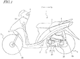
- FIG. 1 is a side view showing an outer construction of a scooter-type motorcycle 1 according to the present embodiment.
- the motorcycle 1 includes a body frame 2 , a body cover 4 , handle bars 6 , a front wheel 7 , a rear speed sensor 8a , a front-wheel speed sensor 8b , a rear wheel 9 , and an engine unit 10 .
- the body cover 4 covers the body frame 2 on the sides.
- the body frame 2 includes a head pipe 2A .
- Front forks 5 are supported by the head pipe 2A .
- Handle bars 6 are attached above the front forks 5 .
- a front-wheel speed sensor 8b is provided, and a front wheel 7 is supported.
- the front-wheel speed sensor 8b detects a rotation speed which is the wheel speed of the front wheel 7 .
- the engine unit 10 is swingingly supported on the body frame 2 , around a pivot axis 3 .
- a rear-wheel speed sensor 8a is provided, and a rear wheel 9 is supported.
- the rear-wheel speed sensor 8a detects a rotation speed which is the wheel speed of the rear wheel 9 .
- the engine unit 10 includes a transmission case 20 .
- the transmission case 20 includes a case body 30 which is fixed to a crankcase 26 ( FIG. 4 ) described below, and a cover 40 which is fixed to the case body 30 .
- the case body 30 houses a continuously variable transmission (CVT) 200 to be described below.
- a kick shaft 25 is attached on a side of the transmission case 20 .
- the engine unit 10 includes the rear wheel 9 , this an example. While including an engine, the engine unit 10 may additionally include any other elements and mechanisms.
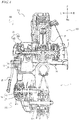
- FIG. 2 schematically shows a construction of the engine unit 10 .
- the engine unit 10 includes an engine 100 , the continuously variable transmission 200 , a centrifugal clutch 300 , a deceleration gear 400 , and the driving wheel (rear wheel) 9 ; in this order, a rotary driving force is transmitted from the engine 100 to the driving wheel 9 .
- the continuously variable transmission 200 transmits motive power from an output shaft 11 (primary shaft 11 ) of the engine 100 to an input shaft of the centrifugal clutch 300 .
- the continuously variable transmission 200 includes the primary shaft 11 , a secondary shaft 12 ( FIG. 5 , to be described later), a primary sheave 13 , a secondary sheave 14 , and a V belt 15 .
- the primary shaft 11 is integral with a crank shaft (not shown) of the engine 100 .
- the secondary shaft 12 is provided in parallel to the primary shaft 11 , and linked to a driving axis 904 of the rear wheel 9 .
- the secondary shaft 12 is a hollow center axis of the secondary sheave 14 , and defines the input shaft of the centrifugal clutch 300 as shown in FIG. 5 to be described later.
- the primary sheave 13 is disposed on the primary shaft 11 , to which output from the engine 100 is transmitted.
- the secondary sheave 14 is disposed on the input shaft of the centrifugal clutch 300 .
- the primary sheave 13 and the secondary sheave 14 each include a stationary flange ( 31 , 41 ) and a movable flange ( 32 , 42 ), which are attached to their rotation axis (the primary shaft 11 and the secondary shaft 12 ). Movement of the movable flange 32 of the primary sheave 13 is controlled by a driving force controller 600 .
- the stationary flange ( 31 , 41 ) and the movable flange ( 32 , 42 ) define a V groove around which the belt is to be wound.
- the V belt 15 is wound around the V grooves of the primary sheave 13 and the secondary sheave 14 , and transmits rotary driving force between both sheaves ( 13 , 14 ).
- the engine unit 10 further includes a groove width adjustment mechanism 16 and a groove width adjustment actuator 17 .
- the groove width adjustment mechanism 16 moves the movable flange 32 of the primary sheave 13 so as to adjust the groove width of the primary sheave 13 .
- the groove width adjustment actuator 17 is an electric motor, for example.
- the centrifugal clutch 300 is attached between the hollow center axis 12 of the secondary sheave 14 (the input shaft of the centrifugal clutch 300 as shown in FIG. 5 to be described later) and a final gear shaft 401 (the output shaft of the centrifugal clutch 300 ) which penetrates through the center axis 12 .
- the centrifugal clutch 300 which is mechanically connected to the engine 100 , includes: a centrifugal clutch upstream member (mainly referred to as a "first mechanism” hereinbelow) which rotates in accordance with rotation of the engine 100 ; and a centrifugal clutch downstream member (mainly referred to as a "second mechanism” hereinbelow) which is mechanically connected to the rear wheel 9 .
- a centrifugal clutch upstream member mainly referred to as a "first mechanism” hereinbelow
- a centrifugal clutch downstream member mainly referred to as a "second mechanism” hereinbelow
- the engine unit 10 further includes the driving force controller 600 .
- the driving force controller 600 is also called an electronic control unit (ECU).
- the electronic control unit (ECU) can be implemented by, for example, an arithmetic circuit (microcomputer (MPU)) and a primary storage device (memory). From a multitude of sensors that are attached to the vehicle, a multitude of vehicle information is input to driving force controller 600 .
- a system that includes not only the driving force controller 600 but also various sensors, a spark plug(s), a fuel injector(s), and various actuators to be controlled by the driving force controller 600 is referred to as a driving force control system in the present specification.
- the MPU of the driving force controller 600 executes an operation in accordance with a flowchart to be described later.
- the operation of the driving force controller 600 will be briefly described.
- a driving system for transmitting the rotary driving force of the engine 100 to the first mechanism, including the engine 100 and the first mechanism of the centrifugal clutch 300 will be referred to as a first driving system; and a driving system for transmitting the rotary driving force of the first mechanism to the rear wheel 9 , including the second mechanism and the rear wheel 9 , will be referred to as a second driving system.
- the driving force controller 600 includes a traction control section 602 ( FIG. 9 ).
- the traction control section 602 is implemented by the MPU executing a computer program which describes a procedure of processing shown in the flowchart, for example.
- the traction control section 602 From a first sensor which detects a rotation speed of the first driving system and a second sensor which detects a rotation speed of the second driving system, respectively, the traction control section 602 acquires the rotation speed of the first driving system and the rotation speed of the second driving system. Then, if the rotation speed of the first driving system is less than a preset control threshold ⁇ and the rotation speed of the second driving system detected by the second sensor is less than a preset control threshold ⁇ , the traction control section 602 suspends the traction control or loosens the traction control. This realizes a kind of straddled vehicle behavior under which the rider is unlikely to feel oddness, as compared to the case where the traction control system is kept activated. Note that the control thresholds ⁇ and ⁇ are stored in the secondary storage device 601 .
- the driving force controller 600 further controls the transmission ratio of the continuously variable transmission 200 .
- the driving force controller 600 may refer to a transmission gear ratio map which is retained in the secondary storage device 601 to vary the transmission ratio of the continuously variable transmission 200 .
- a transmission gear ratio map is a database to be provided in connection with various travel modes during travel, which defines, for example, a target transmission ratio relationship (which provides a target of control) of the continuously variable transmission 200 on the basis of vehicle speed, engine revolution, and throttle position.
- the driving force controller 600 is electrically connected to various sensors to receive signals which are output from the respective sensors, i.e., signals indicating detection results.
- the detection results from the sensors are utilized as various vehicle information of the motorcycle 1 .
- various sensors may include, for example, a flange position detection sensor 19 , a throttle position sensor 91 (TPS), an engine revolution sensor 92 , the wheel speed sensors 8a and 8b ( FIG. 1 ), and a vehicle speed sensor 93 .
- TPS throttle position sensor
- engine revolution sensor 92 the wheel speed sensors 8a and 8b ( FIG. 1 )
- vehicle speed sensor 93 vehicle speed sensor
- the flange position detection sensor 19 detects a position of the movable flange 32 .
- the throttle sensor 91 detects an accelerator position (throttle position).
- the engine revolution sensor 92 detects a revolution of the engine. In the present embodiment, the engine revolution sensor 92 detects a rotation speed of the crank shaft (primary shaft 11 ).
- the rear-wheel speed sensor 8a detects a rotation speed of the driving axis 904 of the driving wheel 9 , i.e., a rear-wheel speed.
- the front-wheel speed sensor 8b ( FIG. 1 ) detects a front-wheel speed as the vehicle speed of the motorcycle 1 .
- the vehicle speed sensor 93 detects a rotation speed of the final gear shaft 401 (the output shaft of the centrifugal clutch 300 ).
- FIG. 3 is an exploded view of the continuously variable transmission 200.
- FIG. 3 mainly shows the engine 100 , the continuously variable transmission 200 , and the centrifugal clutch 300 . Their structural relationship will be understood from FIG. 3 .
- FIG. 4 shows a detailed cross section of the engine unit 10 .
- FIG. 4 shows positioning of the engine 100 , the continuously variable transmission 200 , the centrifugal clutch 300 , and the driving wheel 9 .
- the engine unit 10 includes the crankcase 26 housing the crank shaft 11 , the continuously variable transmission 200 , and the transmission case 20 housing the continuously variable transmission 200 .
- the transmission case 20 is disposed on the left of the crankcase 26 .
- a cylinder 27 is fixed at the front of the crankcase 26 .
- Rotary driving force of the crank shaft 11 is transmitted to the rear wheel 9 via the continuously variable transmission 200 .
- the continuously variable transmission 200 includes the primary sheave 13 at the engine 100 side and the secondary sheave 14 at the rear wheel side.
- FIG. 4 shows relative positioning of the stationary flange 31 and the movable flange 32 composing the primary sheave 13 , and the relative positioning of the stationary flange 41 and the movable flange 42 composing the secondary sheave 14 .
- the V belt 15 is omitted from illustration.
- the front half and the rear half of the primary sheave 13 respectively represent states under different transmission ratios (in other words, states under different belt groove widths). The same is also true of the secondary sheave 14 .
- the final gear shaft 401 is linked to a rear wheel shaft 904 via a gear mechanism not shown.
- FIG. 5 shows a detailed cross section of the centrifugal clutch 300 .
- FIG. 6 shows a state of the centrifugal clutch 300 while the engine 100 is stopped, and
- FIG. 7 shows a state of the centrifugal clutch 300 during travel.
- the centrifugal clutch 300 includes a clutch plate 301 , clutch shoes 302 , clutch springs 303 , and a clutch housing 304 (clutch outer cover).
- the clutch plate 301 is fixedly attached to the center axis 12 of the secondary sheave 14 of the continuously variable transmission 200 .
- Pins 305 with which to mount the clutch shoes 302 are provided in a manner of protruding from the clutch plate 301 .
- three pins 305 are attached at equal intervals along the circumferential direction.
- one end of each clutch shoe 302 is attached to a pin 305 that is attached to the clutch plate 301 , so as to permit pivoting.
- Each clutch spring 303 is mounted so as to link one end of one clutch shoe 302 to another end of a clutch shoe 302 that is adjacent to the one clutch shoe 302 along the circumferential direction.
- Each clutch spring 303 exhibits an elastic reaction force to pull together one end and the other end of adjacent clutch shoes 302 at all times.
- the clutch housing 304 which is a bowl-shaped member, is attached to the final gear shaft 401 penetrating through the hollow center axis 12 of the secondary sheave 14 , so as to provide covering over an assembly 310 of the aforementioned clutch shoes 302 .
- the secondary sheave 14 begins to rotate. With a gradual increase in the revolution of the engine 100 , as shown in FIG. 7 , the resultant centrifugal force causes the assembly 310 of clutch shoes 302 to defy the elastic reaction force of the clutch springs 303 , whereby the assembly 310 of clutch shoes 302 begins to expand in diameter as a whole. As the engine 100 consequently reaches a certain revolution, the clutch shoes 302 come in contact with the clutch housing 304 . Thereafter, a stalled state occurs in which torque is being transmitted while the clutch shoes 302 are slipping against the clutch housing 304 , and then comes a state in which the clutch shoes 302 and the clutch housing 304 are connected due to the frictional force acting between them.
- the centrifugal clutch 300 as such is disclosed in, for example, Japanese Laid-Open Patent Publication No. 2006-71096 .
- the centrifugal clutch 300 achieves clutch engagement/disengagement through contact/non-contact between the clutch shoes 302 and the clutch housing 304 .
- the centrifugal clutch 300 can be generally classified into an upstream-of-centrifugal-clutch path (hereinafter referred to as the "first path") from the engine 100 to the clutch shoes 302 , through which driving force of the engine 100 is transmitted, and a downstream-of-centrifugal-clutch path (hereinafter referred to as the "second path”) from the clutch housing 304 to the final gear shaft 401 .
- first path upstream-of-centrifugal-clutch path
- second path downstream-of-centrifugal-clutch path
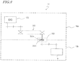
- FIG. 8 is a planar and schematic representation of the structure of the engine unit 10 .
- the centrifugal clutch 300 can be structurally divided into the first mechanism 300a and the second mechanism 300b as mentioned above.
- the first mechanism 300a is mechanically connected to the engine 100 , and rotates in accordance with rotation of the engine 100 .
- the second mechanism 300b is mechanically connected to the rear wheel 9 .
- the first mechanism 300a and the second mechanism 300b are mechanically connected with or disengaged from each other, thereby turning ON or OFF the transmission of rotary driving force from the first mechanism 300a to the second mechanism 300b.
- a driving system constituting the first path including the engine 100 , the continuously variable transmission 200 , the first mechanism 300a , and any driving force transmitting mechanism that provides mechanical connection therebetween, will be referred to as the first driving system 10a .
- a driving system constituting the second path including the second mechanism 300b , the rear wheel 9 , and any driving force transmitting mechanism that provides mechanical connection therebetween, will be referred to as the second driving system 10b .
- the second driving system 10b allows the rotary driving force which is transmitted from the engine 100 to be transmitted to the rear wheel 9 , thereby driving the motorcycle 1 .
- the driving force transmitting mechanism as mentioned above may include one or more gears and one or more rotation axes, for example.
- the driving force controller 600 receives an output signal from the aforementioned first sensor which detects the rotation speed of the first driving system 10a and an output signal from the second sensor which detects the rotation speed of the second driving system 10b , and performs traction control on their basis, thereby controlling the driving force to be supplied to the rear wheel 9.
- the first sensor typically detects the revolution of the engine 100 as a rotation speed of the first driving system 10a .
- the first sensor may be able to detect a rotation speed of any element of the first driving system 10a .
- the first sensor may detect the rotation speed of at least one of the primary shaft 11 , the primary sheave 13 , the secondary sheave 14 , and the first mechanism 300a of the centrifugal clutch 300 .
- the second sensor typically detects the rear-wheel rotation speed as a rotation speed of the second driving system 10b .
- the second sensor may be able to detect a rotation speed of any element of the second driving system 10b .
- the second sensor may detect the rotation speed of at least one of the second mechanism 300b of the centrifugal clutch 300 and the final gear shaft 401 .
- the driving force controller 600 suspends the traction control or loosens the traction control. The details of this process will be described next with reference to FIG. 9 and the subsequent figures.
- the present specification illustrates the shoe-type centrifugal clutch 300 with clutch shoes as an example.
- the centrifugal clutch is not limited to a shoe-type.
- a multi-plate clutch of a centrifugal type is also an example of a centrifugal clutch.
- a multi-plate clutch of a centrifugal type relies on the engine torque and engine revolution to automatically realize engagement/disengagement of the multi-plate clutch.
- a multi-plate clutch of a centrifugal type includes a plurality of drive plates that rotate together with the crank shaft, to which engine rotation is transmitted.
- a plurality of pressure plates are provided at positions opposing the drive plates along the axial direction.
- a multi-plate clutch of a centrifugal type includes a clutch weight(s) which moves in the centrifugal direction depending on the engine revolution to achieve engagement/disengagement between the drive plates and the pressure plates. Separation between the drive plates and the pressure plates corresponds to a state of so-called clutch disengagement.
- the clutch weight(s) moves in the centrifugal direction, whereby the drive plates and the pressure plates come closer together. This allows the rotation of the drive plates to be transmitted to the pressure plates, thus resulting in a state of so-called clutch engagement.
- driving force of the engine 100 is transmitted to the driving wheel 9 .
- a multi-plate clutch of a centrifugal type can also be divided into a first mechanism 300a and a second mechanism 300b as shown in FIG. 8 .
- the drive plates would belong to the first mechanism 300a .
- the pressure plates would belong to the second mechanism 300b .
- a driving system including the engine 100 , the continuously variable transmission 200 , the first mechanism 300a , and any driving force transmitting mechanism that provides mechanical connection therebetween would define the first driving system 10a .
- a driving system including the second mechanism 300b , the rear wheel 9 , and any driving force transmitting mechanism that provides mechanical connection therebetween would define the second driving system 10b .
- FIG. 9 shows functional blocks representing the construction of the driving force control system 610 according to the present embodiment.
- the driving force control system 610 includes the driving force controller 600 , the secondary storage device 601 , a gyroscope 633 , a lateral acceleration sensor 634 , the front-wheel speed sensor 8b , the rear-wheel speed sensor 8a , the throttle sensor 91 , a brake modulator 638 , a vehicle speed calculation section 645 , and a bank angle acquisition section 646 .
- the driving force controller 600 includes the traction control section 602 .
- the traction control section 602 is responsible for traction control of the motorcycle 1 .
- Traction control broadly means controlling the motive power of the engine.
- the traction control section 602 may suppress a rear-wheel slip by decreasing the torque of the engine 100 .
- stepping up suppression of a rear-wheel slip is expressed as "tightening traction control”.
- stepping down suppression of a rear-wheel slip is expressed as "loosening traction control”.
- discontinuing suppression of a rear-wheel slip is expressed as "suspending traction control”. Note that loosening traction control makes it more likely for a rear-wheel slip to occur.
- the inventors have decided to, in a situation where the traction control section 602 is performing traction control, monitor both of the revolution of the engine 100 and the rear-wheel rotation speed, for example, to determine whether or not to continue traction control.
- the control threshold ⁇ may be determined based on a value at which the centrifugal clutch 300 becomes disengaged, and a control threshold ⁇ may be determined based on a rear-wheel speed at which the centrifugal clutch 300 having so far been engaged becomes disengaged. Both of these are values to be defined in the design stage.
- the traction control section 602 suspends the traction control or loosens the traction control, even if there is any remaining rear-wheel slip. This is a control to suppress disengagement of the centrifugal clutch.
- the reason for operating the traction control section 602 in this manner is that the engine revolution and the rear-wheel speed at which engagement of the centrifugal clutch 300 is to be lost are known in the design stage. From the information of engine revolution and rear-wheel speed, it can be determined whether the centrifugal clutch having so far been engaged is anywhere near a state where it will be automatically disengaged. Before an automatic disengagement of the centrifugal clutch occurs, the traction control is suspended or loosened so that engagement of the centrifugal clutch 300 will be maintained, i.e., disengagement of the centrifugal clutch will be suppressed. This makes for less oddness to the rider as caused by disengagement of the centrifugal clutch 300 .
- the driving force controller 600 Upon detecting a lateral skid of the front wheel 7 or the rear wheel 9 , the driving force controller 600 reduces the longitudinal force of each wheel. Longitudinal force is a sum of driving force and braking force.
- the yaw rate of the motorcycle 1 changes.
- the roll rate and the bank angle (roll angle) of the motorcycle 1 change.
- the gyroscope 633 in the present embodiment detects angular velocities along the two axial directions of yaw and roll of the motorcycle 1 . In other words, the gyroscope 633 detects a yaw rate and a roll rate of the motorcycle 1 .
- the detected angular velocity values along these two axes are sent from the gyroscope 633 to the vehicle speed calculation section 645 , the bank angle acquisition section 646 , and a lateral-skid acceleration calculation section 647 .
- the vehicle speed calculation section 645 in the present embodiment is able to calculate not only a vehicle speed at the front-wheel tangential point, but also a vehicle speed at the rear-wheel tangential point.
- a vehicle speed at the rear-wheel tangential point is determined through the above-described arithmetic operations based on the front-wheel speed, the yaw rate, and the bank angle.
- the gyroscope 633 in the present embodiment may function as a yaw rate sensor, and further as a roll rate sensor. In addition to a yaw rate and a roll rate, the gyroscope 633 may be configured to also detect a pitch rate.
- the lateral acceleration sensor 634 detects an acceleration in the lateral direction of the vehicle body of the motorcycle 1 .
- the detected value of lateral acceleration is sent from the lateral acceleration sensor 634 to the bank angle acquisition section 646 in the traction control section 602 .
- the front-wheel speed sensor 8 b detects a rotation speed of the front wheel 7 .
- the rear-wheel speed sensor 8a detects a rotation speed of the rear wheel 9 .
- the detected rotation speeds of the front wheel 7 and the rear wheel 9 are output to the vehicle speed calculation section 645 .
- the throttle sensor 91 detects a position of the throttle.
- the detected value of throttle position is output to the driving force controller 600 .
- the brake modulator 638 detects brake pressures on the front wheel brake and the rear wheel brake (neither of which is shown), and adjusts the respective brake pressures.
- the detected respective brake pressures of the wheels are output to a braking force estimation section 652 .
- the engine revolution sensor 92 , the gyroscope 633 , the lateral acceleration sensor 634 , the throttle sensor 91 , the brake modulator 638 , the vehicle speed calculation section 645 , and the bank angle acquisition section 646 are connected to the inputs of the driving force controller 600 .
- the clutch actuator 614 , the brake modulator 638 , a spark plug 639 , a fuel injector 640 , and a throttle actuator 641 are connected to the outputs of the driving force controller 600 .
- the driving force controller 600 includes the traction control section 602 , a driving force estimation section 651 , the braking force estimation section 652 , and a longitudinal force estimation section 653 .
- the traction control section 602 includes the vehicle speed calculation section 645 , the bank angle acquisition section 646 , the lateral-skid acceleration calculation section 647 , a judgment section 649 , and a longitudinal-force reduction control section 650 .
- the judgment section 649 in the traction control section 602 monitors both of the revolution of the engine 100 as output from the engine revolution sensor 92 and the rear-wheel rotation speed as output from the rear-wheel speed sensor 8a , and determines whether or not to continue traction control.
- the judgment section 649 determines whether the rotation speed of the first driving system 10a (a revolution of the engine as detected by the engine revolution sensor 92 ) is less than the preset control threshold ⁇ and the rotation speed of the second driving system 10b (a rear-wheel rotation speed as detected by the rear-wheel speed sensor 8a ) is less than the preset control threshold ⁇ . Based on the results of judgment, the longitudinal-force reduction control section 650 suspends the traction control or loosens the traction control. More specifically, the longitudinal-force reduction control section 650 cancels or loosens the output reducing operation for traction control, which has been performed for at least one among the spark plug 639 , the fuel injector 640 , and the throttle actuator 641 .
- the driving force controller 600 may detect the lateral skid of each wheel independently, and perform control to reduce the longitudinal force applied to each wheel when a lateral skid is detected.
- the description of the present embodiment assumes that longitudinal-force reduction control associated with such lateral skid detection is to be performed. Next, an exemplary operation of determining presence or absence of a lateral skid by the judgment section 649 will be described.
- a lateral-skid acceleration is acquired based on the vehicle speed, bank angle, lateral acceleration, and yaw rate of the motorcycle 1 .
- the vehicle speed calculation section 645 can acquire vehicle speeds of the motorcycle 1 (i.e., the vehicle speed at the front-wheel tangential point and the vehicle speed at the rear-wheel tangential point) through arithmetic operations based on the outputs of the front-wheel speed sensor 8b , the gyroscope 633 , and the bank angle acquisition section 646 .
- the vehicle speed V(r) at the rear-wheel tangential point can be determined with the following general formula, by using the yaw rate ⁇ z and the bank angle ⁇ .
- V r V f 2 ⁇ f ⁇ ⁇ ⁇ z 2
- the detected wheel speed V f of the front wheel 7 is subjected to arithmetic operations to determine a vehicle speed V(r) at the rear-wheel tangential point r , and this determined value of the V(r) (estimated value) is subjected to arithmetic operations to determine a slip rate or the like.
- the wheel speed V f of the front wheel may be regarded as the vehicle speed V(r) at the rear-wheel tangential point, without employing the calculation of eq. 1 above.
- the vehicle speeds obtained at the vehicle speed calculation section 645 are output to the lateral-skid acceleration calculation section 647 .
- the "vehicle speed" which is used by the bank angle acquisition section 646 of the present embodiment in making a bank angle estimation does not need to be the vehicle speed at the rear-wheel tangential point, but may instead be the vehicle speed at the front-wheel tangential point.
- a difference which is in accordance with the yaw rate and the bank angle occurs between the vehicle speed at the rear-wheel tangential point and the vehicle speed at the front-wheel tangential point. Even if this difference is ignored, estimation errors for the bank angle can still be sufficiently small.
- the roll rate of the motorcycle 1 is input from the gyroscope 633 , and also the lateral acceleration of the motorcycle 1 is input from the lateral acceleration sensor 634 . Based on these input values and the "vehicle speed", the bank angle acquisition section 646 determines a bank angle of the motorcycle 1 .
- the bank angle can be acquired through various methods.
- an initially estimated value of bank angle may be used for the arithmetic operations to derive a vehicle speed at the rear-wheel tangential point, and the vehicle speed (the vehicle speed at the rear-wheel tangential point) which is obtained through these arithmetic operations may then be used to again estimate a bank angle.
- the accuracy of estimation can be enhanced.
- the driving force estimation section 651 estimates a driving force which is transmitted to the driving wheel. Since the driving wheel is the rear wheel 9 in the present embodiment, no driving force is transmitted to the front wheel 7 .
- the driving force of the rear wheel 9 as estimated by the driving force estimation section 651 is output to the longitudinal force estimation section 653 .
- the braking force estimation section 52 estimates the braking force applied to each wheel.
- the estimated braking force of each wheel is output to the longitudinal force estimation section 653 .
- the longitudinal force estimation section 653 calculates a longitudinal force on each wheel.
- the calculated longitudinal force acting on each wheel is output to the longitudinal-force reduction control section 650 .
- the judgment section 649 makes a comparison to see whether the input lateral-skid acceleration exceeds a predetermined threshold or not. If the lateral-skid acceleration value is equal to or greater than the threshold, it is determined that a lateral skid is occurring at the wheel, and a longitudinal-force reduction control signal to reduce longitudinal force acting on the wheel is output to the longitudinal-force reduction control section 650 .
- the longitudinal-force reduction control section 650 Based on the judgment signal which is input from the judgment section 649 , the longitudinal-force reduction control section 650 performs control to reduce the longitudinal force acting on each wheel, as input from the longitudinal force estimation section 653 . If the driving force is greater than the braking force, control is performed to decrease the driving force or increase the braking force. If the braking force is greater than the driving force, control is performed to decrease the braking force or increase the driving force.
- the present embodiment has illustrated a detailed construction of the driving force control system 610 with reference to FIG. 9 . It should be noted that the construction of the driving force control system 610 shown in FIG. 9 , which is an example, includes component elements that are unrelated to the control according to the present invention.
- the component elements that are related to the control according to the present invention include: the rear-wheel speed sensor 8a , the front-wheel speed sensor 8b or the vehicle speed sensor 93 , the engine revolution sensor 92 , the vehicle speed calculation section 645 , the judgment section 649 , and the longitudinal-force reduction control section 650 .
- the traction control section 602 may include the vehicle speed calculation section 645 , the judgment section 649 , and the longitudinal-force reduction control section 650 .
- the judgment section 649 at least receives information of the rear-wheel speed from the vehicle speed calculation section 645 .
- the spark plug 639 , the fuel injector 640 , and the throttle actuator 641 may be included as component elements related to the control according to the present invention. While the spark plug 639 , the fuel injector 640 , and the throttle actuator 641 would all be essential to any generic motorcycle 1 , the present embodiment stipulates at least one of them; the reason is that, in the present embodiment, the output reduction for traction control purposes may be cancelled or loosened with respect to at least one of the spark plug 639 , the fuel injector 640 , and the throttle actuator 641 .
- the above Embodiment is an example of the present invention.
- the driving force control according to the present invention may at least include a first sensor to detect a rotation speed of the first driving system, a second sensor to detect a rotation speed of the second driving system, and a control section to perform traction control.
- This control section may operate so as to suspend the traction control or loosen the traction control when the rotation speed of the first driving system as detected by the first sensor is less than a preset first threshold and the rotation speed of the second driving system as detected by the second sensor is less than a preset second threshold.
- FIG. 10 shows a procedure of processing by the traction control section 602 of the driving force controller 600 according to the present embodiment. This process is executed in a situation where the traction control section 602 is performing traction control.
- step S1 the traction control section 602 determines whether slipping of the rear wheel 9 has been detected or not. If the traction control section 602 has detected slipping of the rear wheel 9 , the process proceeds to step S2 ; if not, the process proceeds to step S5 .
- the latter case means that, thanks to the traction control, slipping of the rear wheel 9 is no longer detected. That is, traction control is no longer necessary.
- step S2 the traction control section 602 determines whether the engine revolution is less than the control threshold ⁇ or not. If the engine revolution is less than the control threshold ⁇ , the process proceeds to step S3 ; otherwise (i.e., equal to or greater than the control threshold ⁇ ), the process proceeds to step S4 .
- step S3 the traction control section 602 determines whether the rear-wheel speed is less than the control threshold ⁇ or not. If the rear-wheel speed is less than the control threshold ⁇ , the process proceeds to step S5 ; otherwise (i.e., equal to or greater than the control threshold ⁇ ), the process proceeds to step S4 .
- Step S4 is executed when the engine revolution is equal to or greater than the control threshold ⁇ and/or the rear-wheel speed is equal to or greater than the control threshold ⁇ .
- the traction control section 602 continues traction control. The process returns to step S1 .
- step S4 is not meant to illustrate the traction control section 602 as performing any special operation, it is nonetheless shown as a step, in order to clarify this operation in its relationship with the process of step S5 to be described next.
- the traction control section 602 suspends the traction control. Instead of suspending the traction control, the traction control section 602 may loosen the traction control.
- control threshold ⁇ to be preset in relation to the engine revolution is, for example, an engine revolution at which the centrifugal clutch 300 engages, which can be known in advance by design.
- control threshold ⁇ to be preset in connection with the rear-wheel speed is, for example, a velocity per hour at which the centrifugal clutch being currently in an engaged state becomes disengaged, which can be known in advance by design.
- control thresholds values other than the aforementioned engine revolution or the velocity per hour at which the centrifugal clutch becomes disengaged by design may also be adopted as control thresholds.
- a value which is greater than the engine revolution at which the centrifugal clutch 300 engages may be adopted as the control threshold ⁇ .
- a value which is higher than the engine revolution at which the first mechanism 300a and the second mechanism 300b having so far been connected become disengaged may be adopted as the control threshold ⁇ .
- the reason for setting such a control threshold(s) ⁇ and/or ⁇ is to account for a response lag of the engine, or slight differences in time between changes in the engine revolution and changes in the rear-wheel speed.
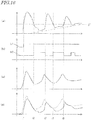
- FIG. 11A shows an instance of traction control activation by the traction control section 602 .
- FIG. 11A(a) shows example waveforms of the engine revolution of the motorcycle 1 and the control threshold ⁇ ;
- FIG. 11A(b) shows example waveforms of the rear-wheel speed and the control threshold ⁇ ;
- FIG. 11A(c) shows example waveforms of the longitudinal acceleration.
- a solid line represents an example waveform when traction control by the traction control section 602 is active.
- any solid-line waveform will be referred to as an "example waveform according to the present invention.
- a dot-dash line represents an example waveform when conventional traction control is active.
- any such waveform will be referred to as an "example conventional waveform”.
- FIG. 11A(b) also shows a waveform indicated by a chain double-dashed line, which represents the front-wheel speed.
- example waveforms according to the present invention will be described.
- differences from the example conventional waveforms will be described.
- an example will be illustrated below where the traction control section 602 suspends the traction control. It must be noted that this is not to exclude examples where the traction control is loosened.
- the traction control section 602 begins traction control. At this point in time, the traction control section 602 executes the process shown in the flowchart of FIG. 10 .
- the engine revolution is equal to or greater than the control threshold ⁇
- the rear-wheel speed is equal to or greater than the control threshold ⁇ .
- Time t1 is exemplified as a point of time at which the engine revolution value or wheel speed exhibits a decreasing tendency.
- the engine revolution is still equal to or greater than the control threshold ⁇ , but the rear-wheel speed becomes less than the control threshold ⁇ .
- the traction control section 602 executes the processes from step S2 to step S4 in FIG. 10 . As a result, traction control is still continued.
- the engine revolution becomes less than the control threshold ⁇ .
- the rear-wheel speed continues to be less than the control threshold ⁇ .
- the traction control section 602 executes the processes of step S2 and S3 , and then step S5 , in FIG. 10 . As a result, the traction control section 602 suspends the traction control.
- Section D1 from times t3 to t4 depicts an increasing engine revolution. Moreover, decrease in the rear-wheel speed is also alleviated.
- the engine revolution begins to be equal to or greater than the control threshold ⁇ .
- the difference between the rear-wheel speed and the front-wheel speed has become so small that traction control is unnecessary.
- the longitudinal acceleration of the motorcycle 1 maintains a positive value without decreasing much. In other words, any decrease in the driving force that is associated with traction control is being suppressed. As a result, occurrence of any vehicle behavior that is unintended by the rider is reduced, whereby a kind of vehicle behavior is realized under which the rider is unlikely to feel oddness.
- the example conventional waveform (the dot-dash line in FIG. 11A ).
- time t3 it is the same as the example waveform according to the present invention.
- traction control is suspended in the example waveform according to the present invention, whereas traction control is continued in the conventional control method. Therefore, the engine revolution in the example conventional waveform ( FIG. 11A(a) ) decreases more rapidly than the engine revolution in the example waveform according to the present invention.
- the rear-wheel speed in the example conventional waveform ( FIG. 11A(b) ) decreases more rapidly than the rear-wheel speed in the example waveform according to the present invention, and approaches the front-wheel speed.
- the result manifests itself in the longitudinal acceleration ( FIG. 11A(c) ): specifically, after time t3 until time t5 , the longitudinal acceleration in the example conventional waveform takes negative values.
- the rider will feel oddness because of this.
- the oddness will continue until the acceleration becomes positive at time t5 .
- FIG. 11B shows example waveforms according to the present invention, paying attention to the rotation speed of the centrifugal clutch 300 .
- FIG. 11B(a) shows an example waveform of the engine revolution of the motorcycle 1 and the control threshold a.
- FIG. 11B(b) shows an example waveform of the rotation speed of the centrifugal clutch 300 .
- a broken line represents an example waveform of the rotation speed of the upstream member of the centrifugal clutch 300
- a solid line represents the rotation speed of the downstream member of the centrifugal clutch 300 .
- a threshold T is the rotation speed at which engagement between the upstream member and the downstream member of the centrifugal clutch 300 is lost. Note that, even when the rotation speed of the upstream member of the centrifugal clutch 300 is less than the threshold T , the upstream member and the downstream member may be in a so-called ride-the-clutch state in a certain situation.
- FIG. 11B(c) shows example waveforms of the respective wheel speeds of the front wheel and rear wheel and the control threshold /3 .
- a broken line represents the front-wheel speed, whereas a solid line represents the rear-wheel speed.
- FIG. 11B(d) shows waveforms of control flags which indicate suspension or activation of traction control.
- the control flag d1 indicates whether traction control is to be universally turned ON or OFF.
- the control flag d1 goes ON at time t1 when the difference between the rear-wheel speed and the front-wheel speed (vehicle speed) becomes equal to or greater than a predetermined value, whereby traction control begins to be activated.
- control flag d2 goes ON (i.e., rises) when the rear-wheel speed becomes less than the control threshold ⁇ , and goes OFF (i.e., falls) when the rear-wheel speed becomes equal to or greater than the control threshold ⁇ .
- the control flag d2 indicates that traction control is temporarily suspended while it is ON, and that traction control is activated while it is OFF.
- portion b1 in the example waveform of FIG. 11B(b) the solid line and the broken line substantially overlap. This means that the upstream member and the downstream member of the centrifugal clutch 300 are engaged, so that their rotation speeds are equal. It can further be seen that the rotation speed is decreasing at portion b1 . This is due to a decrease in the engine revolution shown in (a) , which in turn is a result of traction control being active. Consequently, the driving force that is transmitted to the rear wheel 9 (which is the driving wheel) also decreases, thereby decreasing the rear-wheel speed as indicated with a solid line in (c) .
- the centrifugal clutch 300 transitions from engagement, via a so-called ride-the-clutch state, to disengagement.
- the point in time at which a difference emerges between the rotation speed of the upstream member of the centrifugal clutch 300 (broken line) and the rotation speed of the downstream member (solid line) corresponds to a ride-the-clutch state. Since the rotation speed of the upstream member is above the threshold T , engagement between the upstream member and the downstream member is not completely lost.
- Time t3 represents a point of time of returning to the state where the rotation speed of the upstream member and the rotation speed of the downstream member of the centrifugal clutch 300 are equal.
- the traction control section 602 is exerting control so that, in a state where the rear wheel 9 (which is the driving wheel) is slipping, a reduction rate (A) under non-connection concerning the upstream-of-centrifugal-clutch path is smaller than a reduction rate (B) under connection concerning the upstream-of-centrifugal-clutch path.
- the "reduction rate (A) under non-connection concerning the upstream-of-centrifugal-clutch path” is a reduction rate in the rotation speed of the upstream-of-centrifugal-clutch path when a difference exists between the rotation speed of the upstream member and the rotation speed of the downstream member of the centrifugal clutch 300 (i.e., at time t2 and afterwards).
- the "reduction rate (B) under connection concerning the upstream-of-centrifugal-clutch path” is a reduction rate in the rotation speed of the upstream-of-centrifugal-clutch path when the rotation speed of the upstream member and the rotation speed of the downstream member of the centrifugal clutch 300 are equal before a difference emerges between the rotation speed of the upstream member and the rotation speed of the downstream member of the centrifugal clutch 300 (i.e., before time t2 ).
- being “equal” means, besides being completely equal, there being a deviation without complete equality, with an amount of deviation falling within a predetermined tolerable range.
- some deviation may exist between the rotation speed of the upstream member and the rotation speed of the downstream member of the centrifugal clutch 300 .
- the aforementioned state of being “equal” may be recognized notwithstanding the presence of the same level of difference as such a difference.
- difference means a state of being different beyond what would be regarded as “equal” as defined above, or, there being a difference such that, by design, the upstream member and the downstream member of the centrifugal clutch 300 are regarded as not being engaged (i.e., unconnected).
- the aforementioned "reduction rate" can be determined in terms of waveform, as the gradient of a waveform in portion b1 or b2 .
- FIG. 11B(b) illustrates the range of portion b2 in which to calculate the above reduction rate (A) under non-connection concerning the upstream-of-centrifugal-clutch path is from time t2 to time t3 , this is an example.
- the aforementioned reduction rate (A) under non-connection may be calculated by utilizing the rotation speed of the upstream member of the centrifugal clutch 300 at time t2 and the rotation speed of the upstream member at any point of time earlier than time t3 .
- each reduction rate mentioned above is a value obtained by measuring the rotation speed of the clutch upstream member and the rotation speed of the clutch downstream member when a slip is allowed to occur while keeping a constant accelerator position, for example.
- Each reduction rate similarly referred to in Embodiments 2 and 3, to be described later, is also a value obtained by the same method of measurement.
- the method of measurement may be various. Any method of measurement other than the aforementioned method may also be used.
- a reduction rate (A) under non-connection may be calculated over the entire period under non-connection of the centrifugal clutch 300 , in order to determine whether the above condition is met or not.
- a reduction rate (A) under non-connection may be calculated at least under non-connection, instead of over the entire period under non-connection.
- under non-connection any point in time under an unconnected state is meant. When a start point and an end point of an "unconnected state" are to be envisaged, the start point is a point of time at which the centrifugal clutch 300 becomes disengaged.
- the end point is a point of time after a predetermined amount of time has elapsed since the point of time of entering the unconnected state, after which that state was maintained, for example.
- the end point is a point of time at which, although the centrifugal clutch 300 is in an unconnected state, the rate of increase of the engine revolution or like conditions indicate that the centrifugal clutch 300 is to be engaged.
- a reduction rate (B) under connection concerning the upstream-of-centrifugal-clutch path may be calculated over the entire period under connection, or calculated at least under connection, instead of over the entire period.
- under connection any point in time under a connected state is meant.
- the start point may be a point of time at which a so-called ride-the-clutch state is entered, or a point of time at which the engine rotates at a revolution which by design indicates that the centrifugal clutch 300 is to be engaged.
- the end point may be a point of time at which an engaged state transitions to a ride-the-clutch state, or a point of time at which the engine rotates at a revolution which by design indicates that the centrifugal clutch 300 is to be disengaged.
- the driving force control system 610 adjusts slipping of the driving wheel so that, when the aforementioned reduction rate (A) under non-connection and reduction rate (B) under connection are calculated "under non-connection” and "under connection” as mentioned above, the aforementioned condition is satisfied.
- FIG. 11C , (a) to (d) show example conventional waveforms, paying attention to the rotation speed of the centrifugal clutch.
- FIG. 11C(a) shows an example waveform of the engine revolution.
- FIG. 11C(b) shows example waveforms of the clutch rotation speed.
- a broken line represents an example waveform of the rotation speed of the upstream member of the centrifugal clutch, whereas a solid line represents an example waveform of the rotation speed of the downstream member of the centrifugal clutch 300 .
- a threshold T is the rotation speed at which engagement between the upstream member and the downstream member of the centrifugal clutch is completely lost.
- FIG. 11B(b) it must be noted that there are cases where the upstream member and the downstream member of the centrifugal clutch 300 are in contact (not completely disengaged) even when the rotation speed of the upstream member is less than the threshold T .
- FIG. 11C(c) shows example waveforms of the respective wheel speeds of the front wheel and rear wheel.
- a broken line represents the front-wheel speed, whereas a solid line represents the rear-wheel speed.
- FIG. 11C(d) shows a waveform of a control flag which indicates suspension or activation of traction control. This control flag indicates whether traction control is to be universally turned ON or OFF.
- Time t1 is identical to time t1 in FIG. 11B .
- Time t2 is a point of time at which a difference emerges between the rotation speed of the upstream member and the rotation speed of the downstream member of the centrifugal clutch.
- Time t3 is a point of time at which the difference between the front-wheel speed and the rear-wheel speed is eliminated, i.e., a state where the driving wheel is no longer slipping.
- FIG. 11B(b) look at the broken line before and after time t2 .
- the gradient of the broken line up to time t2 corresponds to the aforementioned reduction rate (B) under connection concerning the upstream-of-centrifugal-clutch path.
- the gradient of the broken line after time t2 corresponds to the aforementioned reduction rate (A) under non-connection concerning the upstream-of-centrifugal-clutch path.
- the reduction rate (A) under non-connection concerning the upstream-of-centrifugal-clutch path and the reduction rate (B) under connection concerning the upstream-of-centrifugal-clutch path are equal.
- the determination of whether to suspend or continue intervention by traction control is made based on whether slipping of the driving wheel has been eliminated or not, which is unrelated to the threshold T , i.e., the rotation speed at which engagement between the upstream member and the downstream member of the centrifugal clutch is completely lost. This is the cause for the oddness to the rider due to disengagement of the centrifugal clutch. It can be said that the concept of ensuring a difference between the aforementioned reduction rate (A) under non-connection and the reduction rate (B) under connection never existed before.
- Embodiment 1 has illustrated an example where, in a situation where traction control is being performed, both of the engine revolution and the rear-wheel speed are checked to suspend the traction control. This operation amounts to canceling traction control and permitting slips. This may mean that the slip suppression performance of the motorcycle 1 could even be further enhanced while reducing oddness to the rider.
- the present embodiment illustrates an operation of restarting traction control after suspending traction control, and conditions therefor.
- the structure and functional blocks of the motorcycle are the same as in Embodiment 1, and their description will not be repeated.
- the traction control section 602 detects the rotation speed of an element in the first driving system 10a , and further detects a value concerning an amount of change thereof.
- the "value concerning an amount of change of the rotation speed" of the first driving system 10a may be a differential value or a difference value of the rotation speed of the first driving system 10a .
- it may be a ratio between the rotation speeds before and after a change. In the case of utilizing the latter ratio, a ratio of the post-change rotation speed to the pre-change rotation speed may be determined, and if the ratio is greater than 1, the rotation speed may be seen as increasing.
- a control threshold may be provided corresponding to that ratio, and the traction control which is currently suspended may be restarted when the rotation speed changes to become equal to or greater than the control threshold.
- the present embodiment assumes that the traction control section 602 computes a differential value of engine revolution.
- FIG. 12 is a procedure of processing by the traction control section 602 according to the present embodiment.
- Steps S1 to S5 are identical to those in FIG. 10 , and their description will not be repeated.
- steps S6 and S7 will be described. Note that step S6 is a process to be performed during suspension of traction control by step S5 .
- the traction control section 602 computes a differential value of engine revolution.
- the differential value is obtained by allowing a difference between an engine revolution at a given point of time and a revolution after the lapse of a predetermined time since the given point of time to be divided by that predetermined time.
- the traction control section 602 determines whether the differential value is less than a control threshold ⁇ or not. If the differential value is less than the control threshold ⁇ , the process returns to step S5 .
- a control threshold ⁇ An example of this condition is where the engine revolution has not increased, or the increase in the rotation speed is smaller than a predetermined level.
- step S7 the process proceeds to step S7 .
- An example of this condition is where the rotation speed has increased to be equal to or greater than a predetermined level, i.e., equal to or greater than the control threshold ⁇ .
- the traction control section 602 restarts traction control. That is, the traction control section 602 decreases the revolution of the engine 100 to suppress torque.
- FIG. 13A shows an instance of traction control activation according to the present embodiment.
- Illustration of FIG. 13A conforms to the illustration of FIG. 11A . That is, FIG. 13A(a) shows example waveforms of the engine revolution of the motorcycle 1 and the control threshold ⁇ ; FIG. 13A(b) shows example waveforms of the rear-wheel speed and the control threshold ⁇ ; and FIG. 13A(c) shows example waveforms of the longitudinal acceleration.
- a solid line represents an example waveform when traction control by the traction control section 602 is active ("example waveform according to the present invention").
- a dot-dash line represents an example waveform when conventional traction control is active ("example conventional waveform").
- a chain double-dashed line in FIG. 13A(b) represents the front-wheel speed. Since the waveform of FIG. 13A does not depict a waveform of a differential value of engine revolution, the control threshold ⁇ is not shown.
- the traction control section 602 suspends the traction control at time t3 . Thereafter, in section D1 from times t3 to t4 , the engine revolution begins to increase. Assume, for example, that the differential value of the engine revolution becomes equal to or greater than the control threshold ⁇ at time t4 .
- the traction control section 602 restarts traction control from time t4 .
- Section D2 in FIG. 13A shows a waveform after traction control is restarted. This is to be contrasted against FIG. 11A .
- the rear-wheel speed does not become equal to the front-wheel speed and thus a slip is occurring in the example of FIG. 11A(b) ; in the example of FIG. 13A(b) , however, the rear-wheel speed becomes equal to the front-wheel speed and thus no slip is occurring.
- traction control is active.
- a condition for restarting once-suspended traction control is set in accordance with an increase in the engine revolution. This method allows traction control to restart more rapidly than under the usual condition of restarting traction control based on a rear-wheel slip. Stated otherwise, traction control can be restarted based on a prediction that the centrifugal clutch 300 will engage.
- the longitudinal acceleration does not become negative through the operation of the present embodiment, either.
- the longitudinal acceleration of the motorcycle 1 still keeps positive, i.e., deceleration does not occur.
- the present embodiment also reduces oddness felt by the rider.
- the control according to the present embodiment is able to restart traction control by predicting that the centrifugal clutch 300 of the motorcycle 1 will engage, and thus the period of performing traction control can be increased relative to the control according to Embodiment 1 above. This reduces the amount of time during which slipping is permitted. As a result, the slip suppression performance can be more enhanced.
- FIG. 13B shows example waveforms according to the present invention, paying attention to the rotation speed of the centrifugal clutch 300 .
- FIG. 13B(a) shows an example waveform of the engine revolution and the control threshold ⁇ .
- FIG. 13B(b) shows example waveforms of the clutch rotation speed.
- a broken line represents an example waveform of the rotation speed of the upstream member of the centrifugal clutch 300
- a solid line represents an example waveform of the rotation speed of the downstream member of the centrifugal clutch 300 .
- a threshold T is a rotation speed at which engagement between the upstream member and the downstream member of the centrifugal clutch 300 is completely lost. As has been described in connection with FIG. 11B(b) in Embodiment 1, it must be noted that there are cases where the upstream member and the downstream member of the centrifugal clutch 300 are in contact (not completely disengaged) even when the rotation speed of the upstream member is less than the threshold T .
- FIG. 13B(c) represents example waveforms of the respective wheel speeds of the front wheel and rear wheel and the control threshold ⁇ .
- a broken line represents the front-wheel speed, whereas a solid line represents the rear-wheel speed.
- FIG. 13B(d) shows waveforms of control flags which indicate suspension or activation of traction control.
- the control flag d1 indicates whether traction control is to be universally turned ON or OFF.
- the control flag d1 goes ON at time t1 when the difference between the rear-wheel speed and the front-wheel speed (vehicle speed) becomes equal to or greater than a predetermined value, whereby traction control begins to be activated.
- control flag d2 indicates that traction control is temporarily suspended while it is ON, and that traction control is activated while it is OFF.
- the traction control section 602 is exerting control so that, in a state where the rear wheel 9 (which is the driving wheel) is slipping, the reduction rate (A) under non-connection concerning the upstream-of-centrifugal-clutch path in portion b2 of FIG. 13B(b) is smaller than the reduction rate (B) under connection concerning the upstream-of-centrifugal-clutch path in portion b1 .
- the present embodiment illustrates an operation of restarting traction control after suspending traction control, and conditions therefor.
- the present embodiment defines a variant of Embodiment 2.
- the structure and functional blocks of the motorcycle are the same as in Embodiment 1, and their description will not be repeated.
- the traction control section 602 utilizes the slip amount of the rear wheel 9 (which is the driving wheel) and an amount of change thereof to calculate a predicted time before the slip disappears (hereinafter referred to as the "predicted slip elimination time").
- the reason for introducing the notion of predicted slip elimination time is to suspend traction control precisely at the point in time when the slip disappears (i.e., the slip amount becomes 0).
- Traction control is a technique for restricting the output of the engine or the like to reduce the driving force that is supplied to the rear wheel 9 (which is the driving wheel) and reduce slips.
- the traction control section 602 continues traction control. On the other hand, if the predicted slip elimination time is less than the control threshold ⁇ and satisfies a further condition, the traction control section 602 suspends the traction control.
- the traction control section 602 first calculates a slip acceleration.
- slip acceleration is in units of [m/s 2 ], where "m” is distance (meter) and “s” is time (second).
- Slip acceleration is determined as a time differential of slip velocity (unit: m/s).
- Slip velocity is a value which is obtained by subtracting the front-wheel speed from the rear-wheel speed.
- the traction control section 602 is able to determine a slip acceleration by dividing a difference in slip velocity at two given points of time by the difference in time.
- the two given points of time may be at a time interval over which 4 to 5 samples will be acquired.
- predicted slip elimination time s ⁇ 1 ⁇ slip velocity / slip acceleration
- the reason for the multiplication by the negative sign is to invert the sign so that the predicted slip elimination time will be determined as a positive amount of time in the present embodiment. Multiplication by the negative sign is not essential. In the case where the sign is not inverted, the condition set forth below may be regarded as true when being equal to or greater than a threshold and yet less than zero.
- FIG. 14 shows a procedure of processing by the traction control section 602 according to the present embodiment.
- Steps S1 and S6 are the same as in FIG. 12 , and their description is omitted. Hereinafter, steps S7 to S10 will be described.
- the traction control section 602 determines whether the predicted slip elimination time satisfies the condition of being greater than 0 and smaller than the control threshold ⁇ .
- the control threshold ⁇ is 500 ms, for example. If the condition is met, the process proceeds to step S8; if it is not met, the process proceeds to step S9 to continue traction control.
- the traction control section 602 determines whether the vehicle speed (e.g., the front-wheel speed) is less than a control threshold ⁇ or not. This determination is made in order to restrict the condition for temporarily suspending the traction control to only the case where the centrifugal clutch 300 is in a ride-the-clutch state. If the vehicle speed is less than the control threshold ⁇ , the process proceeds to step S6 ; otherwise, the process proceeds to step S9 .
- the vehicle speed e.g., the front-wheel speed
- Step S6 is a comparison between a differential value of engine revolution and the control threshold ⁇ , as has been described in Embodiment 2. This determination is made because there is no need to temporarily suspend traction control if the engine revolution has not decreased.
- the traction control section 602 utilizes the slip velocity of the rear wheel 9 (which is the driving wheel) and an amount of change (slip acceleration) thereof to predict an amount of time required until a slip disappears. Then, the traction control section 602 temporarily interrupt TCS before the amount of time until the slip disappears actually becomes zero (i.e., 0 ⁇ predicted slip elimination time ⁇ control threshold ⁇ ), thus minimizing lack of driving force. This allows to reduce any vehicle behavior that is not intended by the rider.
- FIG. 15, (a) to (e) shows example waveforms according to the present invention, paying attention to the rotation speed of the centrifugal clutch 300 .
- FIG. 15(a) shows an example waveform of the engine revolution.
- FIG. 15(b) shows example waveforms of the clutch rotation speed.
- a broken line represents an example waveform of the rotation speed of the upstream member of the centrifugal clutch 300
- a solid line represents an example waveform of the rotation speed of the downstream member of the centrifugal clutch 300 .
- a threshold T is a rotation speed at which engagement between the upstream member and the downstream member of the centrifugal clutch 300 is completely lost.
- FIG. 15(c) shows example waveforms of the respective wheel speeds of the front wheel and rear wheel and the control threshold ⁇ .
- a broken line represents a front-wheel speed, which corresponds to the vehicle speed, whereas a solid line represents the rear-wheel speed.
- FIG. 15(d) shows example waveforms of predicted slip elimination time and the control threshold ⁇ .
- FIG. 15(e) shows waveforms of control flags which indicate suspension or activation of traction control.
- the control flag e1 indicates whether traction control is to be universally turned ON or OFF.
- the control flag e1 goes ON at time t1 when the difference between the rear-wheel speed and the front-wheel speed (vehicle speed) becomes equal to or greater than a predetermined value, whereby traction control begins to be activated.
- control flag e2 indicates that traction control is temporarily suspended while it is ON, and that traction control is activated while it is OFF.
- traction control In a situation where traction control is ON, it goes ON (i.e., rises) when: the predicted slip elimination time is greater than 0 and less than the control threshold ⁇ ; the vehicle speed is less than the control threshold ⁇ ; and a differential value of the engine revolution is less than the control threshold ⁇ .
- the predicted slip elimination time is greater than 0 and less than the control threshold ⁇ as shown in (d) , the front-wheel speed (broken line) representing the vehicle speed is less than the control threshold ⁇ , and the differential value of the engine revolution is less than the control threshold ⁇ ; therefore, the control flag e2 goes ON. As a result, traction control is temporarily suspended.
- the rotation speed of the upstream member of the centrifugal clutch 300 increases, whereby the centrifugal clutch 300 engages and the rotation speed of the downstream member increases. As a result of this, driving force is supplied to the rear wheel 9 of the motorcycle 1 , so that the rider can continue riding without feeling oddnesses associated with lack of driving force.
- rises and falls of the control flag e2 are not necessarily in synchronization with the engine revolution in (a) , the rotation speed of the upstream member of the centrifugal clutch (broken line) in (b) , or the rear-wheel speed (solid line) in (c) .
- the reason is that the operation needs to undergo mechanical changes based on the control flags, rather than being able to immediately follow along.
- the present embodiment also performs a control which is similar to those in Embodiments 1 and 2. That is, the traction control section 602 is exerting control so that, in a state where the rear wheel 9 (which is the driving wheel) is slipping, the reduction rate (A) under non-connection concerning the upstream-of-centrifugal-clutch path in portion b2 of FIG. 15(b) is smaller than the reduction rate (B) under connection concerning the upstream-of-centrifugal-clutch path in portion b1.
- the above embodiments illustrate engine revolution as an example of rotation speed of an element in the first driving system 10a , and rear-wheel speed as an example of rotation speed of an element in the second driving system 10b .
- a slip amount may be adopted as a basis for determining whether or not to apply traction control.
- a slip amount is obtained by subtracting the front-wheel speed from the rear-wheel speed.
- a control threshold may be provided for the slip amount, and at step S3 in FIG. 10 and FIG. 12 , the process may branch out depending on whether the slip amount is less than the control threshold or not.
- both of engine revolution and rear-wheel speed are utilized in determining whether to suspend or continue traction control.
- Each of these can be said to be an example of utilizing physical parameters in both the first driving system 10a (upstream-of-centrifugal-clutch path) and the second driving system 10b (downstream-of-centrifugal-clutch path).
- a "physical parameter" may be rotation speed (i.e., the number of rotations per unit time) or torque, for example (hereinafter the same applies throughout the present specification).
- a physical parameter in either one of the first driving system 10a (upstream-of-centrifugal-clutch path) and the second driving system 10b (downstream-of-centrifugal-clutch path) may be utilized in determining whether to suspend or continue traction control.
- FIG. 16 shows an example of utilizing a rotation speed in the second driving system 10b (downstream-of-centrifugal-clutch path) in determining whether to suspend or continue traction control.
- FIG. 16 is an example of utilizing the wheel speed of the rear wheel 9 (which is the driving wheel) as a rotation speed in the second driving system 10b (downstream-of-centrifugal-clutch path).
- FIG. 16(a) shows a waveform of the rear-wheel speed
- FIG. 16(b) shows waveforms of control flags which indicate suspension or activation of traction control.
- FIG. 16(c) shows the engine revolution
- FIG. 16(d) shows the rotation speed of the centrifugal clutch.
- FIG. 16(a) shows the front-wheel speed with a chain double-dashed line, where a control threshold ⁇ ' is indicated by a broken line parallel to the horizontal axis.
- Time t1 is a point of time at which the rear-wheel speed becomes equal to or greater than the control threshold ⁇ '.
- the solid line b1 in FIG. 16(b) is a control flag indicating whether traction control is to be universally turned ON or OFF.
- This control flag goes ON at time t1 when the difference between the rear-wheel speed and the front-wheel speed (vehicle speed) becomes equal to or greater than a predetermined value, whereby traction control begins to be activated.
- time t1 is exemplified as a point of time at which the engine revolution value or wheel speed exhibits a decreasing tendency.
- a solid line b2 in FIG. 16(b) indicates, in a situation where traction control is ON, a control flag which goes ON (i.e., rises) when the rear-wheel speed becomes less than the control threshold ⁇ ', and goes OFF (i.e., falls) when the rear-wheel speed becomes equal to or greater than the control threshold ⁇ '.
- the control flag of the solid line b2 indicates that traction control is temporarily suspended while it is ON, and that traction control is activated while it is OFF.
- traction control is temporarily suspended between times t2 and t3 and between times t4 and t5 .
- the engine revolution increases as shown in FIG. 16(c) .
- the clutch rotation speed also increases.
- a broken line represents the rotation speed of the upstream member of the centrifugal clutch
- a solid line represents the rotation speed of the downstream member of the centrifugal clutch.
- Embodiment 1 it is possible to determine whether to suspend or continue traction control by only utilizing rotation speed in the second driving system 10b (downstream-of-centrifugal-clutch path).
- Embodiment 1 it is possible to determine whether to suspend or continue traction control by utilizing a rotation speed in the first driving system 10a (upstream-of-centrifugal-clutch path).
- This variant is realized by utilizing e.g. engine revolution, rather than the rotation speed of the rear-wheel speed as shown in FIG. 16(a) . It would also be possible to utilize the rotation speed of any element other than the engine that is included in the upstream-of-centrifugal-clutch path.
- a revolution (or the rotation speed of any other element corresponding thereto) at which the centrifugal clutch 300 having so far been engaged becomes disengaged may be set as a control threshold, and the control flag may be allowed to go ON at a point in time at which it becomes less than the control threshold, thereby temporarily suspending traction control. Then, when the revolution becomes equal to or greater than the control threshold, traction control may be restarted again.
- Embodiment 2 where a differential value of engine revolution is utilized. In other words, it is possible to determine whether to suspend or continue traction control by only utilizing the rotation speed of one or more elements in the upstream-of-centrifugal-clutch path.
- conditional branching in steps S2 , S3 , and S6 of FIG. 10 or 12 is illustrated as determining whether a given velocity is less than a control threshold or not.
- “less than” may alternatively read “equal to or smaller than”.
- the expression “less than, or equal to or smaller than” indicates that either one is interchangeably applicable.
- a state in which ... is slipping the condition for identifying a slip has not been particularly mentioned; this is because it may vary depending on the conditions that are specific to the vehicle.
- the state which is recognized as an occurrence of slipping may vary depending on the design concept (off-road model, on-road model, etc.) of the vehicle, tire wear, road surface states, and the like.
- a slip amount is utilized in the evaluation as to whether a slip is occurring or not
- a slip rate may be used instead. The choice as to which one is used would vary depending on the vehicle's specific design. At least, when the "slipping" condition which is set specifically to the vehicle is met, "a state in which ... is slipping" exists in the meaning of the present specification.
- the present invention is practicable not only in terms of manufacture, sale, use, or the like of driving force control system, but also in the form of a vehicle equipped with such a driving force control system.
- a straddled vehicle may also encompass a 3-wheel motorcycle and an ATV.
- Three-wheel motorcycles come in a type with one driving wheel, and also a type with plural driving wheels.
- an ATV usually has plural driving wheels.
- the above-described embodiments are straightforwardly applicable to any 3-wheel motorcycle with one driving wheel.
- the types of 3-wheel motorcycles and ATVs with plural driving wheels the above-described embodiments would be applicable with respect to each driving wheel.
- Other possible examples of vehicles include ROVs (Recreational Off-Highway Vehicles), snowmobiles, and so on.
- the present invention is applicable to any vehicle in which a centrifugal clutch is mounted and which is capable of traction control.
- the driving force control system according to the present invention is broadly applicable to straddled vehicles having a front wheel and a rear wheel.
- This system is broadly usable in the attitude control technique for straddled vehicles which include a centrifugal clutch and which are equipped with a traction control system (TCS).
- TCS traction control system
Landscapes
- Engineering & Computer Science (AREA)
- Chemical & Material Sciences (AREA)
- Combustion & Propulsion (AREA)
- Mechanical Engineering (AREA)
- General Engineering & Computer Science (AREA)
- Transportation (AREA)
- Automation & Control Theory (AREA)
- Hydraulic Clutches, Magnetic Clutches, Fluid Clutches, And Fluid Joints (AREA)
- One-Way And Automatic Clutches, And Combinations Of Different Clutches (AREA)
- Control Of Vehicle Engines Or Engines For Specific Uses (AREA)
Abstract
Description
- The present invention relates to driving force control in a vehicle having a centrifugal clutch mounted therein.
-
Patent Document 1 describes a motorcycle of a scooter type in which a centrifugal clutch is mounted. The motorscooter described inPatent Document 1 is equipped with a driving force control system. A driving force control system is a control system which adjusts slipping of the driving wheel. A centrifugal clutch is a clutch which engages based on a centrifugal force that occurs from rotation. - [Patent Document 1]
Japanese Laid-Open Patent Publication No. 5-240076 - In the scooter-type motorcycle described in
Patent Document 1 in which a centrifugal clutch is mounted, the rider may feel oddness when slipping of the driving wheel is adjusted. - An objective of the present invention is to provide a driving force control system which can reduce the oddness felt by a rider, being suitable for a vehicle including a centrifugal clutch.
- (P1-1) A driving force control system according to the present invention is a driving force control system for use in a vehicle, the vehicle including an engine, a driving wheel to be driven by motive power from the engine, and a centrifugal clutch provided in a transmission path of motive power between the engine and the driving wheel, the driving force control system being to adjust slipping of the driving wheel in a state in which the driving wheel is slipping, wherein, the centrifugal clutch includes an upstream member mechanically connected to the engine to rotate, and a downstream member to be mechanically connected with or disengaged from the upstream member based on a centrifugal force occurring in accordance with rotation of the upstream member, and, with a centrifugal force which is in accordance with rotation of the upstream member, automatically turns ON or OFF transmission of motive power between an upstream-of-centrifugal-clutch path from the engine to the upstream member and a downstream-of-centrifugal-clutch path from the downstream member to the driving wheel; and the driving force control system exerts control so that, in a state in which the driving wheel is slipping, a reduction rate (A) under non-connection concerning the upstream-of-centrifugal-clutch path is smaller than a reduction rate (B) under connection concerning the upstream-of-centrifugal-clutch path. The reduction rate (A) under non-connection concerning the upstream-of-centrifugal-clutch path is a reduction rate in rotation speed of the upstream-of-centrifugal-clutch path when a difference exists between a rotation speed of the upstream member of the centrifugal clutch and a rotation speed of the downstream member of the centrifugal clutch. The reduction rate (B) under connection concerning the upstream-of-centrifugal-clutch path is a reduction rate in rotation speed of the upstream-of-centrifugal-clutch path when a rotation speed of the upstream member of the centrifugal clutch is equal to a rotation speed of the downstream member of the centrifugal clutch before a difference emerges between a rotation speed of the upstream member of the centrifugal clutch and a rotation speed of the downstream member of the centrifugal clutch.
- When a vehicle is equipped with the driving force control system according to the present invention with the above construction, it becomes possible to reduce oddness to the rider while allowing the driving force control system of the vehicle to exhibit its functions.
- (P1-2) In the driving force control system according to (P1-1) above, through continuous control so that the reduction rate (A) under non-connection concerning the upstream-of-centrifugal-clutch path is smaller than the reduction rate (B) under connection in a state in which the driving wheel is slipping, the rotation speed of the upstream member of the centrifugal clutch equals the rotation speed of the downstream member of the centrifugal clutch.
- (P1-3) The driving force control system according to (P1-1) above may rely on at least one of a physical parameter concerning rotation of the upstream path and a physical parameter concerning rotation of the downstream path, in exerting control so that the reduction rate (A) under non-connection concerning the upstream-of-centrifugal-clutch path is smaller than the reduction rate (B) under connection.
- (P1-4) The driving force control system according to (P1-3) above may rely on the physical parameter concerning rotation of the upstream path and the physical parameter concerning rotation of the downstream path, in exerting control so that the reduction rate (A) under non-connection concerning the upstream-of-centrifugal-clutch path is smaller than the reduction rate (B) under connection.
- (P1-5) The driving force control system according to (P1-1) above may further rely on a rate of change in one of a physical parameter concerning rotation of the upstream path and a physical parameter concerning rotation of the downstream path, in exerting control so that the reduction rate (A) under non-connection concerning the upstream-of-centrifugal-clutch path is smaller than the reduction rate (B) under connection.
- (P1-6) The driving force control system according to (P1-1) above may include a control section to perform traction control in a state in which the driving wheel is slipping, wherein the control section may suspend the traction control or loosen the traction control in exerting control so that the reduction rate (A) under non-connection concerning the upstream-of-centrifugal-clutch path is smaller than the reduction rate (B) under connection.
- (P1-7) The driving force control system according to (P1-6) above may further comprise a first sensor to detect a rotation speed of the upstream path, and a second sensor to detect a rotation speed of the downstream path; and the control section may suspend the traction control or loosen the traction control when the rotation speed of the upstream path detected by the first sensor is less than, or equal to or smaller than, a preset first threshold and the rotation speed of the downstream path detected by the second sensor is less than, or equal to or smaller than, a preset second threshold.
- (P1-8) The control section of the driving force control system according to (P1-6) or (P1-7) above may perform the traction control by adjusting revolution of the engine in the upstream path.
- (P1-9) In the driving force control system according to (P1-7) above, the first threshold may be set to a value higher than a rotation speed of the upstream path at which the upstream path and the downstream path having so far been connected is to be disconnected.
- (P1-10) The second threshold in the driving force control system according to (P1-7) above may be set to a value higher than a rotation speed of the downstream path at which the upstream path and the downstream path having so far been connected is to be disconnected.
- (P1-11) In the driving force control system according to any of (P1-7) to (P1-10) above, the first sensor may detect a value concerning revolution of the engine in the upstream path; and the second sensor may detect a value concerning rotation speed of the driving wheel in the downstream path.
- (P1-12) In the driving force control system according to (P1-11) above, in a situation where the traction control is suspended or loosened, the control section may begin the traction control or tighten the traction control when a value concerning an amount of change of revolution of the engine becomes equal to or greater than a preset third threshold.
- (P1-13) The control section of the driving force control system according to (P1-12) above may suspend the traction control or loosen the traction control when a value which is in accordance with a rate of change in one of the rotation speed of the upstream path detected by the first sensor and the rotation speed of the downstream path detected by the second sensor becomes less than, or equal to or smaller than, a preset third threshold.
- (P1-14) The driving force control system according to (P1-13) above may further comprise a third sensor to detect a vehicle speed of the vehicle, wherein, the second sensor may detect a value concerning rotation speed of the driving wheel in the downstream path; and the control section may suspend the traction control or loosen the traction control when a value which is in accordance with a rate of change in a slip velocity based on a rotation speed of the driving wheel detected by the second sensor and the vehicle speed detected by the third sensor becomes less than, or equal to or smaller than, the third threshold.
- (P1-15) The control section of the driving force control system according to (P1-14) above may suspend the traction control or loosen the traction control further when the vehicle speed detected by the third sensor becomes equal to or smaller than a fourth threshold.
- (P1-16) A vehicle according to the present invention comprises: the driving force control system of any of (P1-1) to (P1-15) above; the engine; the driving wheel; and the centrifugal clutch.
- (P1-17) The vehicle according to (P1-16) above may further comprise a non-driving wheel.
- (P2-1) A driving force control system according to the present invention is a driving force control system for use in a vehicle, the vehicle including an engine, a driving wheel to be driven by motive power from the engine, and a centrifugal clutch provided in a transmission path of motive power between the engine and the driving wheel, the driving force control system being to adjust slipping of the driving wheel in a state in which the driving wheel is slipping, wherein, the centrifugal clutch includes an upstream member mechanically connected to the engine to rotate, and a downstream member to be mechanically connected with or disengaged from the upstream member based on a centrifugal force occurring in accordance with rotation of the upstream member, and, with a centrifugal force which is in accordance with rotation of the upstream member, automatically turns ON or OFF transmission of motive power between an upstream-of-centrifugal-clutch path from the engine to the upstream member and a downstream-of-centrifugal-clutch path from the downstream member to the driving wheel. In a state in which the driving wheel is slipping, the driving force control system exerts control to suppress disengagement of the centrifugal clutch in accordance with at least one of a physical parameter concerning rotation of the upstream-of-centrifugal-clutch path and a physical parameter concerning rotation of the downstream-of-centrifugal-clutch path.
- When a vehicle is equipped with the driving force control system according to the present invention with the above construction, it becomes possible to reduce oddness to the rider while allowing the driving force control system of the vehicle to exhibit its functions.
- (P2-2) The driving force control system according to (P2-1) above may, in a state in which the driving wheel is slipping, rely on the physical parameter concerning rotation of the upstream-of-centrifugal-clutch path and the physical parameter concerning rotation of the downstream-of-centrifugal-clutch path in exerting control to suppress disengagement of the centrifugal clutch.
- (P2-3) The driving force control system according to (P2-1) above may, in a state in which the driving wheel is slipping, rely on the physical parameter concerning rotation of the upstream-of-centrifugal-clutch path in exerting control to suppress disengagement of the centrifugal clutch.
- (P2-4) The driving force control system according to (P2-1) above may, in a state in which the driving wheel is slipping, rely on the physical parameter concerning rotation of the downstream-of-centrifugal-clutch path in exerting control to suppress disengagement of the centrifugal clutch.
- (P2-5) In the driving force control system according to (P2-2) above, a control threshold α may be provided for the physical parameter concerning rotation of the upstream-of-centrifugal-clutch path and a control threshold β may be provided for the physical parameter concerning rotation of the downstream-of-centrifugal-clutch path, and the driving force control system may exert control to suppress disengagement of the centrifugal clutch when the physical parameter concerning rotation of the upstream-of-centrifugal-clutch path is less than, or equal to or smaller than, the control threshold α and the physical parameter concerning rotation of the downstream-of-centrifugal-clutch path is less than, or equal to or smaller than, the control threshold β.
- (P2-6) In the driving force control system according to any of (P2-1) to (P2-5) above, the physical parameter concerning rotation of the upstream-of-centrifugal-clutch path may be rotation speed or torque.
- (P2-7) The driving force control system according to (P2-1) above may include a control section to perform traction control of, in a state in which the driving wheel is slipping, controlling motive power of the engine to adjust slipping of the driving wheel, wherein the control section may suspend the traction control or loosen the traction control as the control to suppress disengagement of the centrifugal clutch.
- (P2-8) The driving force control system according to (P2-7) above may further comprise a first sensor to detect the physical parameter concerning rotation of the upstream-of-centrifugal-clutch path and a second sensor to detect the physical parameter concerning rotation of the downstream-of-centrifugal-clutch path, wherein the control section may suspend the traction control or loosen the traction control when the physical parameter concerning rotation of the upstream-of-centrifugal-clutch path detected by the first sensor is less than, or equal to or smaller than, a preset control threshold α and a rotation speed of the physical parameter concerning rotation of the downstream-of-centrifugal-clutch path detected by the second sensor is less than, or equal to or smaller than, a preset control threshold β.
- (P2-9) In the driving force control system according to (P2-7) or (P2-8) above, in a situation where the traction control is suspended or loosened, the control section may begin the traction control or tighten the traction control when a value concerning an amount of change of a physical parameter concerning rotation of the upstream-of-centrifugal-clutch path becomes equal to or greater than the preset control threshold γ.
- (P2-10) In the driving force control system according to (P2-9) above, the control threshold α may be set to a value higher than a physical parameter concerning rotation of the upstream-of-centrifugal-clutch path at which the upstream-of-centrifugal-clutch path and the downstream-of-centrifugal-clutch path having so far been connected are to be disconnected.
- (P2-11) In the driving force control system according to (P2-9) above, the control threshold β may be set to a value higher than a physical parameter concerning rotation of the downstream-of-centrifugal-clutch path at which the upstream-of-centrifugal-clutch path and the downstream-of-centrifugal-clutch path having so far been connected are to be disconnected.
- (P2-12) In the driving force control system according to (P2-10) above, a condition for performing the traction control may be preset in the vehicle; the condition may include a condition value concerning revolution of the engine; and the control threshold α may be set as a value concerning revolution of the engine.
- (P2-13) In the driving force control system according to (P2-11) above, a condition for performing the traction control may be preset in the vehicle; the condition may include a condition value concerning rotation speed of the driving wheel; and the control threshold β may be set as a value concerning rotation speed of the driving wheel.
- (P2-14) A vehicle according to the present invention comprises: the driving force control system of any of (P2-1) to (P2-13) above; the engine; the driving wheel; and the centrifugal clutch.
- (P2-15) The vehicle according to (P2-12) above may further comprise a non-driving wheel.
- In a state in which the driving wheel is slipping, the above driving force control system performs control to suppress disengagement of the centrifugal clutch, in accordance with at least one of a physical parameter concerning rotation of the upstream-of-centrifugal-clutch path and a physical parameter concerning rotation of the downstream-of-centrifugal-clutch path. By equipping a vehicle with such a driving force control system, or in a vehicle equipped with such a driving force control system, it is possible to reduce oddness to the rider while allowing the control system of the vehicle to exhibit its functions.
- According to an illustrative driving force control system of the present invention, in a state in which a driving wheel is slipping, control is exerted so that the above-defined reduction rate (A) under non-connection concerning an upstream-of-centrifugal-clutch path is smaller than the above-defined reduction rate (B) under connection concerning an upstream-of-centrifugal-clutch path. By equipping a vehicle with such a driving force control system, or in a vehicle equipped with such a driving force control system, it is possible to reduce oddness to the rider while allowing the control system of the vehicle to exhibit its functions.
-
- [
FIG. 1 ] A side view showing an outer construction of a scooter-type motorcycle 1 according toEmbodiment 1. - [
FIG. 2 ] A schematic diagram showing a construction of anengine unit 10. - [
FIG. 3 ] An exploded view of a continuouslyvariable transmission 200. - [
FIG. 4 ] A detailed cross-sectional view of theengine unit 10. - [
FIG. 5 ] A detailed cross-sectional view of acentrifugal clutch 300. - [
FIG. 6 ] A diagram showing a state of thecentrifugal clutch 300 while theengine 100 is stopped. - [
FIG. 7 ] A diagram showing a state of thecentrifugal clutch 300 during travel. - [
FIG. 8 ] A schematic diagram of the structure of theengine unit 10. - [
FIG. 9 ] A functional block diagram showing the construction of a drivingforce control system 610 according toEmbodiment 1. - [
FIG. 10 ] A flowchart showing a procedure of processing by atraction control section 602 in a drivingforce controller 600 according toEmbodiment 1. - [
FIG. 11A] (a) to (c) are waveform diagrams showing an instance of traction control activation by thetraction control section 602. - [
FIG. 11B] (a) to (d) are diagrams showing example waveforms according to the present invention, paying attention to the rotation speed of thecentrifugal clutch 300. - [
FIG. 11C] (a) to (d) are diagrams example conventional waveforms, paying attention to the rotation speed of the centrifugal clutch. - [
FIG. 12 ] A flowchart showing a procedure of processing by atraction control section 602 according toEmbodiment 2. - [
FIG. 13A] (a) to (c) are waveform diagrams showing an instance of traction control activation according toEmbodiment 2. - [
FIG. 13B] (a) to (d) are diagrams showing example waveforms according to the present invention, paying attention to the rotation speed of thecentrifugal clutch 300. - [
FIG. 14 ] A flowchart showing a procedure of processing by atraction control section 602 according toEmbodiment 3. - [
FIG. 15 ] (a) to (e) are diagrams showing example waveforms according to the present invention, paying attention to the rotation speed of thecentrifugal clutch 300. - [
FIG. 16 ] (a) to (d) are waveform diagrams showing an instance of traction control activation according to a variant. - A centrifugal clutch to be adopted in a vehicle is structurally characterized that it allows a plurality of transmission paths of motive power to be automatically, and mechanically, connected or disconnected depending on a travel state (e.g., a state of engine revolution) of the vehicle.
- As used herein, "automatically" means not requiring the rider to directly perform the manipulations of engaging and disengaging the clutch. The centrifugal clutch is automatically manipulated in accordance with a travel state of the vehicle. The centrifugal clutch is a clutch which, depending on the magnitude of a centrifugal force which occurs in component members of the centrifugal clutch in accordance with the travel state of the vehicle, mechanically connects or disconnects the plurality of transmission paths of motive power. Engagement and disengagement of the centrifugal clutch do not require any conscious clutch manipulations to be made by the rider.
- As mentioned above, "to mechanically connect or disconnect a plurality of transmission paths of motive power" means structurally connecting together the plurality of transmission paths of motive power so that a driving force which is generated by the engine will be transmitted, or structurally disconnecting them so that the aforementioned driving force will not be transmitted.
- Further in the present specification, construction related to a centrifugal clutch is defined as follows. The detailed construction of a centrifugal clutch and the details of a transmission path of motive power will be later described with reference to
FIGS. 6 to 8 ; nonetheless, construction related to a centrifugal clutch is defined as below. For ease of understanding, reference numerals of the component elements as indicated inFIG. 8 will occasionally be mentioned in the following definitions. - An "upstream member of the centrifugal clutch" is a member to be mechanically connected to the engine of a vehicle. An upstream member of the centrifugal clutch is mechanically linked with the engine, and always rotates in harmony with the engine rotation. While the engine is stopped, the upstream member of the centrifugal clutch is also stopped. As the upstream member rotates, centrifugal force of a magnitude which is in accordance with the magnitude of its rotation speed will act on the upstream member. A rotating radius of a movable member which is provided on the upstream member keeps increasing with the centrifugal force, until the upstream member comes in contact with a downstream member of the centrifugal clutch (which will be described next), and eventually becomes mechanically connected with it. The upstream member of the centrifugal clutch corresponds to a
first mechanism 300a, for example, inFIG. 8 . - A "downstream member of the centrifugal clutch" is a member to be mechanically connected with or disengaged from the upstream member, depending on the magnitude of a centrifugal force which occurs with engine rotation. In a state of being mechanically connected with the upstream member, the downstream member of the centrifugal clutch rotates in harmony with engine rotation. In a state of being mechanically disengaged from the upstream member, the downstream member of the centrifugal clutch rotates at a different rotation speed from the revolution of the engine, or is stopped even though the engine may be rotating. The downstream member of the centrifugal clutch corresponds to a
second mechanism 300b, for example, inFIG. 8 . - An "upstream-of-centrifugal-clutch path" refers to, within a transmission path of motive power through which the motive power generated by the engine is transmitted to the driving wheel, the path from the engine to the upstream member of the centrifugal clutch. The motive power that is generated by the engine is always transmitted in the upstream-of-centrifugal-clutch path. The upstream-of-centrifugal-clutch path undergoes rotation with engine rotation, and comes to a stop when the engine stops. In other words, the upstream-of-centrifugal-clutch path undergoes rotation integrally with the engine. The upstream-of-centrifugal-clutch path corresponds to a
first driving system 10a, for example, inFIG. 8 . - A "downstream-of-centrifugal-clutch path" refers to, within a transmission path of motive power through which the motive power generated by the engine is transmitted to the driving wheel, the path from the downstream member of the centrifugal clutch to the driving wheel. Depending on the situation which the centrifugal clutch is in, the downstream-of-centrifugal-clutch path may transmit the same or different motive power as/from that in the upstream-of-centrifugal-clutch path, or does not transmit any motive power.
- As follows, transmission of motive power is more specifically described. When the upstream member and the downstream member of the centrifugal clutch are mechanically connected, the rotation speed of the upstream member of the centrifugal clutch and the rotation speed of the downstream member will be equal if the upstream member and the downstream member of the centrifugal clutch are rotating in a completely integral manner. As a result, the downstream-of-centrifugal-clutch path transmits the same motive power as does the upstream-of-centrifugal-clutch path. This state is a state in which the centrifugal clutch is completely engaged.
- Note that, generally speaking, even at an engine revolution at which the centrifugal clutch can be regarded as completely engaging by design, some deviation (difference) may exist between the rotation speed of the upstream member of the centrifugal clutch and the rotation speed of the downstream member. A "state in which the centrifugal clutch is completely engaging" or a "state in which the rotation speed of the upstream member and the rotation speed of the downstream member of the centrifugal clutch are equal" may be recognized notwithstanding the presence of the same level of difference as such a difference.
- On the other hand, when the upstream member and the downstream member of the centrifugal clutch are mechanically connected but are slipping, i.e., when the centrifugal clutch is in a ride-the-clutch state, the downstream-of-centrifugal-clutch path transmits different motive power from that in the upstream-of-centrifugal-clutch path. The "centrifugal clutch being in a ride-the-clutch state" means an intermediate state, which is a transient state, between a state where the centrifugal clutch is engaging and a state where the centrifugal clutch is disengaged. In a ride-the-clutch state, the rotation speed of the upstream member and the rotation speed of the downstream member of the centrifugal clutch are not equal. The downstream-of-centrifugal-clutch path corresponds to a
second driving system 10b, for example, inFIG. 8 . - The centrifugal clutch automatically turns ON or OFF the aforementioned transmission of motive power between the upstream-of-centrifugal-clutch path and the downstream-of-centrifugal-clutch path, depending on the magnitude of the centrifugal force which is in accordance with the revolution of the engine. Unlike any clutch that is manipulated by the rider, a centrifugal clutch is a clutch which does not allow the rider to arbitrarily control connection or disconnection of the transmission path of motive power.
- The inventors have earnestly studied the state in which the driving wheel of a vehicle having a centrifugal clutch mounted therein is slipping. In particular, the inventors have studied a vehicle which includes a centrifugal clutch and which is also equipped with a driving force control system. Herein, a driving force control system is a system that performs the control of adjusting the slipping of the driving wheel in a state in which the driving wheel is slipping.
- To "adjust slipping" means varying the revolution of the engine so as to control the slip to a target level. As used herein, "slipping" refers to a physical parameter which is expressed as a slip amount or a slip rate of the driving wheel, for example. Adjustment of slipping encompasses increasing the slip to a target level, or decreasing the slip to a target level. In order to vary the revolution of the engine, an electronically controlled throttle or a fuel injector may be operated, for example, to vary the amount of fuel supplied to the engine. The same also holds true in the following description.
- It has been found through the study that situations may arise where, as the driving force control system intervenes to adjust the slipping of the driving wheel, the centrifugal force changes as a function of the engine rotation, whereby the centrifugal clutch may be automatically disengaged. What should be noted here is the fact that disengagement of the centrifugal clutch is automatically achieved in accordance with the magnitude of centrifugal force, and not by the rider's will. Also note that it is not dependent on the rider's will whether the driving force control system is to intervene or not.
- The inventors have found out that, due to complex relationship between the centrifugal clutch and the driving force control system operating irrespective of the rider's will, the rider experiences a feeling of oddness concerning the vehicle behavior. As used herein, "oddness" means an oddness that is felt by a rider of a vehicle which goes through different behavior from the behavior that is intended by the rider.
- In order to reduce oddness to the rider, it is necessary to operate the centrifugal clutch in a manner of accounting for the relationship between the centrifugal clutch and the driving force control system.
- Therefore, the inventors have decided to control a reduction rate (A) under non-connection concerning the upstream-of-centrifugal-clutch path, defined as below, is smaller than a reduction rate (B) under connection concerning the upstream-of-centrifugal-clutch path, defined as below, when in a state in which the driving wheel is slipping.
- Reduction rate (A) under non-connection concerning the upstream-of-centrifugal-clutch path: a reduction rate in the rotation speed of the upstream-of-centrifugal-clutch path when a difference exists between the rotation speed of the upstream member of the centrifugal clutch and the rotation speed of the downstream member of the centrifugal clutch.
- Reduction rate (B) under connection concerning the upstream-of-centrifugal-clutch path: a reduction rate in the rotation speed of the upstream-of-centrifugal-clutch path when the rotation speed of the upstream member of the centrifugal clutch is equal to the rotation speed of the downstream member of the centrifugal clutch before a difference emerges between the rotation speed of the upstream member of the centrifugal clutch and the rotation speed of the downstream member of the centrifugal clutch.
- As a result, in a state in which the driving wheel is slipping, while adjusting slipping of the driving wheel, it is possible to reduce a decrease in the centrifugal force of the upstream member of the centrifugal clutch, which causes the centrifugal clutch to automatically engage or disengage, when a difference exists between the rotation speed of the upstream-of-centrifugal-clutch path and the rotation speed of the downstream-of-centrifugal-clutch path. As a result, a driving force control system is provided which can reduce oddness felt by the rider while being able to adjust slipping of the driving wheel.
- Moreover, the inventors have conceived of controlling the state of engagement of the centrifugal clutch, in a state in which the driving wheel is slipping; or more specifically, performing control to suppress disengagement of the centrifugal clutch in accordance with at least one of a physical parameter concerning rotation of the upstream-of-centrifugal-clutch path and a physical parameter concerning rotation of the downstream-of-centrifugal-clutch path, in a state in which the driving wheel is slipping. As used herein, a "physical parameter" may be rotation speed (i.e., the number of rotations per unit time) or torque, for example (hereinafter the same applies throughout the present specification).
- In "a state in which the driving wheel is slipping", the driving force control system is intervening to perform the control of adjusting the slipping of the driving wheel, whereby the rotation speed of the centrifugal clutch has begun to slow down. A rotation speed at which disconnection will occur between the upstream-of-centrifugal-clutch path and the downstream-of-centrifugal-clutch path currently being connected is known in advance by design. Therefore, especially by checking the physical parameter(s) concerning rotation of the upstream-of-centrifugal-clutch path and/or the downstream-of-centrifugal-clutch path, it is possible to infer whether the centrifugal clutch risks becoming disengaged or not. If the centrifugal clutch risks becoming disengaged, control may be performed to suppress disengagement of the centrifugal clutch, whereby disengagement of the centrifugal clutch is suppressed while adjusting the slipping in a state in which the driving wheel is slipping; thus, oddness felt by the rider can be reduced. In other words, the aforementioned control to suppress disengagement of the centrifugal clutch has proven effective. Oddness to the rider can be more appropriately reduced by relying on both of the physical parameter concerning rotation of the upstream-of-centrifugal-clutch path and the physical parameter concerning rotation of the downstream-of-centrifugal-clutch path, in performing the control to suppress disengagement of the centrifugal clutch.
- The question of whether oddness is felt to the rider or not may be mapped to acceleration values of the vehicle, for example. The description in the present specification assumes that, in the aforementioned situation where the centrifugal clutch risks becoming disengaged, the rider will not feel oddness (a velocity decrease) unless the vehicle has a negative acceleration value, i.e., unless it is decelerating. When the acceleration value of the vehicle becomes negative, the rider perceives a velocity decrease (deceleration) of the vehicle. However, the determination as to whether the rider will feel oddness or not is not limited to the above. It may be determined that oddness is being felt to the rider when the centrifugal clutch becomes disengaged; it may be determined that oddness is being felt to the rider when the velocity of travel of the vehicle is low in view of the rider's manipulation; and various other determinations would also be possible.
- In the present specification, "disengagement of the centrifugal clutch" means the connection between the upstream-of-centrifugal-clutch path and the downstream-of-centrifugal-clutch path becoming lost for a period sufficiently long for the rider to perceive a velocity decrease of the vehicle, or longer. Typically, "disengagement of the centrifugal clutch" occurs when the upstream-of-centrifugal-clutch path and the downstream-of-centrifugal-clutch path become completely disconnected so that the vehicle decelerates.
- To "suppress disengagement of the centrifugal clutch" is a notion broadly encompassing any control to avoid disengagement of the centrifugal clutch. For example, in a situation where the rotation speed of the centrifugal clutch decreases to a point where the centrifugal clutch risks becoming disengaged, increasing the engine revolution to increase the rotation speed of the centrifugal clutch, thereby maintaining its engagement, corresponds to suppressing disengagement of the centrifugal clutch. Moreover, when the centrifugal clutch is in a ride-the-clutch state, increasing the engine revolution to restore engagement of the centrifugal clutch, without causing any perceivable velocity decrease of the vehicle to the rider, also corresponds to suppressing disengagement of the centrifugal clutch. Furthermore, even if connection between the upstream-of-centrifugal-clutch path and the downstream-of-centrifugal-clutch path is temporarily lost, suppression of disengagement of the centrifugal clutch may be envisaged in some cases, i.e., where the engine revolution is increased to restore engagement of the centrifugal clutch before a perceivable velocity decrease of the vehicle to the rider occurs. Suppression of disengagement of the centrifugal clutch may be attained by not only increasing the engine revolution, but also by maintaining the engine revolution, or slowing a decrease in the engine revolution. As compared to any conventional slip adjustment control, the present invention can be said to perform a kind of control which ensures that the clutch is less likely to become disengaged.
- Based on the above terminology, the inventors have accomplished a driving force control system as follows, and also a vehicle which is equipped with such a driving force control system.
- Hereinafter, with reference to the attached drawings, embodiments of the driving force control system according to the present invention, and straddled vehicles each being one example of a vehicle equipped with the driving force control system, will be described. The present specification will illustrate scooter-type motorcycles as embodiments of straddled vehicles. However, this is only an example. Any motorcycles other than scooter types are also applicable, and 3-wheel motorcycles having three wheels, all-terrain vehicles (ATVs), and the like are also encompassed within straddled vehicles.
- In the following description, unless otherwise specified, front, rear, left, and right respectively refer to the front, rear, left, and right as viewed from the rider of the motorcycle. Symbols F, Re, L, and R in the figures respectively represent front, rear, left, and right.
- In the present embodiment, identical component elements will be denoted by identical reference numerals, and any redundant description thereof will be omitted.
- First, an overall construction of the motorcycle will be briefly described.
-
FIG. 1 is a side view showing an outer construction of a scooter-type motorcycle 1 according to the present embodiment. - As shown in
FIG. 1 , themotorcycle 1 includes abody frame 2, abody cover 4, handlebars 6, a front wheel 7, arear speed sensor 8a, a front-wheel speed sensor 8b, arear wheel 9, and anengine unit 10. - The
body cover 4 covers thebody frame 2 on the sides. Thebody frame 2 includes ahead pipe 2A.Front forks 5 are supported by thehead pipe 2A. Handle bars 6 are attached above thefront forks 5. At a lower end of thefront forks 5, a front-wheel speed sensor 8b is provided, and a front wheel 7 is supported. The front-wheel speed sensor 8b detects a rotation speed which is the wheel speed of the front wheel 7. - The
engine unit 10 is swingingly supported on thebody frame 2, around apivot axis 3. At a rear end of theengine unit 10, a rear-wheel speed sensor 8a is provided, and arear wheel 9 is supported. The rear-wheel speed sensor 8a detects a rotation speed which is the wheel speed of therear wheel 9. - The
engine unit 10 includes atransmission case 20. Thetransmission case 20 includes acase body 30 which is fixed to a crankcase 26 (FIG. 4 ) described below, and acover 40 which is fixed to thecase body 30. Thecase body 30 houses a continuously variable transmission (CVT) 200 to be described below. Akick shaft 25 is attached on a side of thetransmission case 20. - Hereinafter, with reference to
FIG. 2 , a detailed construction of theengine unit 10 will be described. Although the present specification illustrates that theengine unit 10 includes therear wheel 9, this an example. While including an engine, theengine unit 10 may additionally include any other elements and mechanisms. -
FIG. 2 schematically shows a construction of theengine unit 10. - The
engine unit 10 includes anengine 100, the continuouslyvariable transmission 200, acentrifugal clutch 300, adeceleration gear 400, and the driving wheel (rear wheel) 9; in this order, a rotary driving force is transmitted from theengine 100 to thedriving wheel 9. - The continuously
variable transmission 200 transmits motive power from an output shaft 11 (primary shaft 11) of theengine 100 to an input shaft of thecentrifugal clutch 300. Generally, the continuouslyvariable transmission 200 includes theprimary shaft 11, a secondary shaft 12 (FIG. 5 , to be described later), aprimary sheave 13, asecondary sheave 14, and aV belt 15. - In the present embodiment, the
primary shaft 11 is integral with a crank shaft (not shown) of theengine 100. Thesecondary shaft 12 is provided in parallel to theprimary shaft 11, and linked to a drivingaxis 904 of therear wheel 9. Thesecondary shaft 12 is a hollow center axis of thesecondary sheave 14, and defines the input shaft of thecentrifugal clutch 300 as shown inFIG. 5 to be described later. - The
primary sheave 13 is disposed on theprimary shaft 11, to which output from theengine 100 is transmitted. Thesecondary sheave 14 is disposed on the input shaft of thecentrifugal clutch 300. - In the present embodiment, the
primary sheave 13 and thesecondary sheave 14 each include a stationary flange (31, 41) and a movable flange (32, 42), which are attached to their rotation axis (theprimary shaft 11 and the secondary shaft 12). Movement of themovable flange 32 of theprimary sheave 13 is controlled by a drivingforce controller 600. The stationary flange (31, 41) and the movable flange (32, 42) define a V groove around which the belt is to be wound. TheV belt 15 is wound around the V grooves of theprimary sheave 13 and thesecondary sheave 14, and transmits rotary driving force between both sheaves (13, 14). - The
engine unit 10 further includes a groovewidth adjustment mechanism 16 and a groovewidth adjustment actuator 17. Driven by the groovewidth adjustment actuator 17, the groovewidth adjustment mechanism 16 moves themovable flange 32 of theprimary sheave 13 so as to adjust the groove width of theprimary sheave 13. The groovewidth adjustment actuator 17 is an electric motor, for example. By varying the groove width of thesecondary sheave 14 so as to be able to sandwich theV belt 15 in accordance with the groove width of theprimary sheave 13, the belt-type continuouslyvariable transmission 200 changes its transmission ratio. - The
centrifugal clutch 300 is attached between thehollow center axis 12 of the secondary sheave 14 (the input shaft of thecentrifugal clutch 300 as shown inFIG. 5 to be described later) and a final gear shaft 401 (the output shaft of the centrifugal clutch 300) which penetrates through thecenter axis 12. - The
centrifugal clutch 300 will be described in outline. Thecentrifugal clutch 300, which is mechanically connected to theengine 100, includes: a centrifugal clutch upstream member (mainly referred to as a "first mechanism" hereinbelow) which rotates in accordance with rotation of theengine 100; and a centrifugal clutch downstream member (mainly referred to as a "second mechanism" hereinbelow) which is mechanically connected to therear wheel 9. In accordance with the magnitude of a centrifugal force acting on the first mechanism in accordance with revolution of theengine 100, the first mechanism and the second mechanism are mechanically connected with or disengaged from each other, thereby turning ON or OFF the transmission of rotary driving force from the first mechanism to the second mechanism. Details of thecentrifugal clutch 300 will be described later with reference toFIG. 5 ,FIG. 6, and FIG. 7 . Moreover, details of the first mechanism and the second mechanism will be described with reference toFIG. 8 . - The
engine unit 10 further includes the drivingforce controller 600. The drivingforce controller 600 is also called an electronic control unit (ECU). The electronic control unit (ECU) can be implemented by, for example, an arithmetic circuit (microcomputer (MPU)) and a primary storage device (memory). From a multitude of sensors that are attached to the vehicle, a multitude of vehicle information is input to drivingforce controller 600. A system that includes not only the drivingforce controller 600 but also various sensors, a spark plug(s), a fuel injector(s), and various actuators to be controlled by the drivingforce controller 600 is referred to as a driving force control system in the present specification. - Using the vehicle information which is input thereto, the MPU of the driving
force controller 600 executes an operation in accordance with a flowchart to be described later. The operation of the drivingforce controller 600 will be briefly described. Hereinafter, a driving system for transmitting the rotary driving force of theengine 100 to the first mechanism, including theengine 100 and the first mechanism of thecentrifugal clutch 300, will be referred to as a first driving system; and a driving system for transmitting the rotary driving force of the first mechanism to therear wheel 9, including the second mechanism and therear wheel 9, will be referred to as a second driving system. - The driving
force controller 600 includes a traction control section 602 (FIG. 9 ). Thetraction control section 602 is implemented by the MPU executing a computer program which describes a procedure of processing shown in the flowchart, for example. - From a first sensor which detects a rotation speed of the first driving system and a second sensor which detects a rotation speed of the second driving system, respectively, the
traction control section 602 acquires the rotation speed of the first driving system and the rotation speed of the second driving system. Then, if the rotation speed of the first driving system is less than a preset control threshold α and the rotation speed of the second driving system detected by the second sensor is less than a preset control threshold β, thetraction control section 602 suspends the traction control or loosens the traction control. This realizes a kind of straddled vehicle behavior under which the rider is unlikely to feel oddness, as compared to the case where the traction control system is kept activated. Note that the control thresholds α and β are stored in thesecondary storage device 601. - The driving
force controller 600 further controls the transmission ratio of the continuouslyvariable transmission 200. For example, based on vehicle information such as vehicle speed and throttle position, the drivingforce controller 600 may refer to a transmission gear ratio map which is retained in thesecondary storage device 601 to vary the transmission ratio of the continuouslyvariable transmission 200. A transmission gear ratio map is a database to be provided in connection with various travel modes during travel, which defines, for example, a target transmission ratio relationship (which provides a target of control) of the continuouslyvariable transmission 200 on the basis of vehicle speed, engine revolution, and throttle position. - The driving
force controller 600 is electrically connected to various sensors to receive signals which are output from the respective sensors, i.e., signals indicating detection results. The detection results from the sensors are utilized as various vehicle information of themotorcycle 1. Examples of various sensors may include, for example, a flangeposition detection sensor 19, a throttle position sensor 91 (TPS), anengine revolution sensor 92, thewheel speed sensors FIG. 1 ), and avehicle speed sensor 93. Hereinafter, "throttle position sensor" may be abbreviated as "throttle sensor". - Among the above, the flange
position detection sensor 19 detects a position of themovable flange 32. Thethrottle sensor 91 detects an accelerator position (throttle position). Theengine revolution sensor 92 detects a revolution of the engine. In the present embodiment, theengine revolution sensor 92 detects a rotation speed of the crank shaft (primary shaft 11). - The rear-
wheel speed sensor 8a detects a rotation speed of the drivingaxis 904 of thedriving wheel 9, i.e., a rear-wheel speed. The front-wheel speed sensor 8b (FIG. 1 ) detects a front-wheel speed as the vehicle speed of themotorcycle 1. Thevehicle speed sensor 93 detects a rotation speed of the final gear shaft 401 (the output shaft of the centrifugal clutch 300). -
FIG. 3 is an exploded view of the continuouslyvariable transmission 200.FIG. 3 mainly shows theengine 100, the continuouslyvariable transmission 200, and thecentrifugal clutch 300. Their structural relationship will be understood fromFIG. 3 . - Next, the structure of the
engine unit 10 will be described with reference toFIG. 4 , and thereafter the structure of thecentrifugal clutch 300 will be described with reference toFIG. 5 . -
FIG. 4 shows a detailed cross section of theengine unit 10. For ease of understanding,FIG. 4 shows positioning of theengine 100, the continuouslyvariable transmission 200, thecentrifugal clutch 300, and thedriving wheel 9. - The
engine unit 10 includes thecrankcase 26 housing thecrank shaft 11, the continuouslyvariable transmission 200, and thetransmission case 20 housing the continuouslyvariable transmission 200. Thetransmission case 20 is disposed on the left of thecrankcase 26. Acylinder 27 is fixed at the front of thecrankcase 26. Rotary driving force of thecrank shaft 11 is transmitted to therear wheel 9 via the continuouslyvariable transmission 200. - As has been described in connection with
FIG. 2 , the continuouslyvariable transmission 200 includes theprimary sheave 13 at theengine 100 side and thesecondary sheave 14 at the rear wheel side.FIG. 4 shows relative positioning of thestationary flange 31 and themovable flange 32 composing theprimary sheave 13, and the relative positioning of thestationary flange 41 and themovable flange 42 composing thesecondary sheave 14. In order to avoid complexity, theV belt 15 is omitted from illustration. InFIG. 4 , the front half and the rear half of theprimary sheave 13 respectively represent states under different transmission ratios (in other words, states under different belt groove widths). The same is also true of thesecondary sheave 14. - The
final gear shaft 401 is linked to arear wheel shaft 904 via a gear mechanism not shown. -
FIG. 5 shows a detailed cross section of thecentrifugal clutch 300.FIG. 6 shows a state of thecentrifugal clutch 300 while theengine 100 is stopped, andFIG. 7 shows a state of thecentrifugal clutch 300 during travel. - As shown in
FIG. 5 to FIG. 7 , thecentrifugal clutch 300 includes aclutch plate 301,clutch shoes 302,clutch springs 303, and a clutch housing 304 (clutch outer cover). - As shown in
FIG. 5 , theclutch plate 301 is fixedly attached to thecenter axis 12 of thesecondary sheave 14 of the continuouslyvariable transmission 200.Pins 305 with which to mount theclutch shoes 302 are provided in a manner of protruding from theclutch plate 301. In the example shown inFIG. 6 , threepins 305 are attached at equal intervals along the circumferential direction. As shown inFIG. 6 , one end of eachclutch shoe 302 is attached to apin 305 that is attached to theclutch plate 301, so as to permit pivoting. Eachclutch spring 303 is mounted so as to link one end of oneclutch shoe 302 to another end of aclutch shoe 302 that is adjacent to the oneclutch shoe 302 along the circumferential direction. Eachclutch spring 303 exhibits an elastic reaction force to pull together one end and the other end of adjacentclutch shoes 302 at all times. Theclutch housing 304, which is a bowl-shaped member, is attached to thefinal gear shaft 401 penetrating through thehollow center axis 12 of thesecondary sheave 14, so as to provide covering over anassembly 310 of the aforementioned clutch shoes 302. - While the
engine 100 is stopped, as shown inFIG. 6 , theassembly 310 ofclutch shoes 302 is reduced in diameter as a whole, due to elastic reaction force of the clutch springs 303. As a result, theclutch shoes 302 and theclutch housing 304 are not in contact. - When the
engine 100 is started, thesecondary sheave 14 begins to rotate. With a gradual increase in the revolution of theengine 100, as shown inFIG. 7 , the resultant centrifugal force causes theassembly 310 ofclutch shoes 302 to defy the elastic reaction force of the clutch springs 303, whereby theassembly 310 ofclutch shoes 302 begins to expand in diameter as a whole. As theengine 100 consequently reaches a certain revolution, theclutch shoes 302 come in contact with theclutch housing 304. Thereafter, a stalled state occurs in which torque is being transmitted while theclutch shoes 302 are slipping against theclutch housing 304, and then comes a state in which theclutch shoes 302 and theclutch housing 304 are connected due to the frictional force acting between them. As a result, a torque which is in accordance with the frictional force acting between them is transmitted to thefinal gear shaft 401. Thecentrifugal clutch 300 as such is disclosed in, for example,Japanese Laid-Open Patent Publication No. 2006-71096 - As will be understood from the above explanation, the
centrifugal clutch 300 achieves clutch engagement/disengagement through contact/non-contact between theclutch shoes 302 and theclutch housing 304. On account of this structural role, thecentrifugal clutch 300 can be generally classified into an upstream-of-centrifugal-clutch path (hereinafter referred to as the "first path") from theengine 100 to theclutch shoes 302, through which driving force of theengine 100 is transmitted, and a downstream-of-centrifugal-clutch path (hereinafter referred to as the "second path") from theclutch housing 304 to thefinal gear shaft 401. -
FIG. 8 is a planar and schematic representation of the structure of theengine unit 10. - As shown in
FIG. 8 , thecentrifugal clutch 300 can be structurally divided into thefirst mechanism 300a and thesecond mechanism 300b as mentioned above. Thefirst mechanism 300a is mechanically connected to theengine 100, and rotates in accordance with rotation of theengine 100. On the other hand, thesecond mechanism 300b is mechanically connected to therear wheel 9. In accordance with the magnitude of a centrifugal force acting on thefirst mechanism 300a in accordance with revolution of theengine 100, thefirst mechanism 300a and thesecond mechanism 300b are mechanically connected with or disengaged from each other, thereby turning ON or OFF the transmission of rotary driving force from thefirst mechanism 300a to thesecond mechanism 300b. - Now, a driving system constituting the first path, including the
engine 100, the continuouslyvariable transmission 200, thefirst mechanism 300a, and any driving force transmitting mechanism that provides mechanical connection therebetween, will be referred to as thefirst driving system 10a. - Moreover, a driving system constituting the second path, including the
second mechanism 300b, therear wheel 9, and any driving force transmitting mechanism that provides mechanical connection therebetween, will be referred to as thesecond driving system 10b. Thesecond driving system 10b allows the rotary driving force which is transmitted from theengine 100 to be transmitted to therear wheel 9, thereby driving themotorcycle 1. Note that the driving force transmitting mechanism as mentioned above may include one or more gears and one or more rotation axes, for example. - The driving force controller 600 (
FIG. 2 ) receives an output signal from the aforementioned first sensor which detects the rotation speed of thefirst driving system 10a and an output signal from the second sensor which detects the rotation speed of thesecond driving system 10b, and performs traction control on their basis, thereby controlling the driving force to be supplied to therear wheel 9. - The first sensor typically detects the revolution of the
engine 100 as a rotation speed of thefirst driving system 10a. However, this is an example; the first sensor may be able to detect a rotation speed of any element of thefirst driving system 10a. For instance, the first sensor may detect the rotation speed of at least one of theprimary shaft 11, theprimary sheave 13, thesecondary sheave 14, and thefirst mechanism 300a of thecentrifugal clutch 300. - Moreover, the second sensor typically detects the rear-wheel rotation speed as a rotation speed of the
second driving system 10b. However, the second sensor may be able to detect a rotation speed of any element of thesecond driving system 10b. For example, the second sensor may detect the rotation speed of at least one of thesecond mechanism 300b of thecentrifugal clutch 300 and thefinal gear shaft 401. - When the rotation speed of the
first driving system 10a as detected by the first sensor is less than the preset control threshold α and the rotation speed of thesecond driving system 10b as detected by the second sensor is less than the preset control threshold β, the drivingforce controller 600 suspends the traction control or loosens the traction control. The details of this process will be described next with reference toFIG. 9 and the subsequent figures. - The present specification illustrates the shoe-type
centrifugal clutch 300 with clutch shoes as an example. However, the centrifugal clutch is not limited to a shoe-type. For example, a multi-plate clutch of a centrifugal type is also an example of a centrifugal clutch. - A multi-plate clutch of a centrifugal type relies on the engine torque and engine revolution to automatically realize engagement/disengagement of the multi-plate clutch.
- A multi-plate clutch of a centrifugal type includes a plurality of drive plates that rotate together with the crank shaft, to which engine rotation is transmitted. A plurality of pressure plates are provided at positions opposing the drive plates along the axial direction. Furthermore, a multi-plate clutch of a centrifugal type includes a clutch weight(s) which moves in the centrifugal direction depending on the engine revolution to achieve engagement/disengagement between the drive plates and the pressure plates. Separation between the drive plates and the pressure plates corresponds to a state of so-called clutch disengagement. When the engine revolution exceeds a predetermined velocity, the clutch weight(s) moves in the centrifugal direction, whereby the drive plates and the pressure plates come closer together. This allows the rotation of the drive plates to be transmitted to the pressure plates, thus resulting in a state of so-called clutch engagement. As a result of this, driving force of the
engine 100 is transmitted to thedriving wheel 9. - The construction of a multi-plate clutch of a centrifugal type can also be divided into a
first mechanism 300a and asecond mechanism 300b as shown inFIG. 8 . Specifically, the drive plates would belong to thefirst mechanism 300a. On the other hand, the pressure plates would belong to thesecond mechanism 300b. Thus, in the case of adopting a multi-plate clutch of a centrifugal type, a driving system including theengine 100, the continuouslyvariable transmission 200, thefirst mechanism 300a, and any driving force transmitting mechanism that provides mechanical connection therebetween would define thefirst driving system 10a. Similarly, a driving system including thesecond mechanism 300b, therear wheel 9, and any driving force transmitting mechanism that provides mechanical connection therebetween would define thesecond driving system 10b. -
FIG. 9 shows functional blocks representing the construction of the drivingforce control system 610 according to the present embodiment. The drivingforce control system 610 includes the drivingforce controller 600, thesecondary storage device 601, agyroscope 633, alateral acceleration sensor 634, the front-wheel speed sensor 8b, the rear-wheel speed sensor 8a, thethrottle sensor 91, abrake modulator 638, a vehiclespeed calculation section 645, and a bankangle acquisition section 646. - The driving
force controller 600 includes thetraction control section 602. Thetraction control section 602 is responsible for traction control of themotorcycle 1. Traction control broadly means controlling the motive power of the engine. For example, thetraction control section 602 may suppress a rear-wheel slip by decreasing the torque of theengine 100. - In the present specification, stepping up suppression of a rear-wheel slip, so as to make it less likely for a rear-wheel slip to occur, is expressed as "tightening traction control". On the other hand, in a situation where traction control is being performed, stepping down suppression of a rear-wheel slip is expressed as "loosening traction control". In a situation where traction control is being performed, discontinuing suppression of a rear-wheel slip is expressed as "suspending traction control". Note that loosening traction control makes it more likely for a rear-wheel slip to occur.
- The inventors have decided to, in a situation where the
traction control section 602 is performing traction control, monitor both of the revolution of theengine 100 and the rear-wheel rotation speed, for example, to determine whether or not to continue traction control. For example, in connection with the engine revolution, the control threshold α may be determined based on a value at which thecentrifugal clutch 300 becomes disengaged, and a control threshold β may be determined based on a rear-wheel speed at which thecentrifugal clutch 300 having so far been engaged becomes disengaged. Both of these are values to be defined in the design stage. If the engine revolution and the rear-wheel speed become less than the respective thresholds under traction control, thetraction control section 602 suspends the traction control or loosens the traction control, even if there is any remaining rear-wheel slip. This is a control to suppress disengagement of the centrifugal clutch. - The reason for operating the
traction control section 602 in this manner is that the engine revolution and the rear-wheel speed at which engagement of thecentrifugal clutch 300 is to be lost are known in the design stage. From the information of engine revolution and rear-wheel speed, it can be determined whether the centrifugal clutch having so far been engaged is anywhere near a state where it will be automatically disengaged. Before an automatic disengagement of the centrifugal clutch occurs, the traction control is suspended or loosened so that engagement of thecentrifugal clutch 300 will be maintained, i.e., disengagement of the centrifugal clutch will be suppressed. This makes for less oddness to the rider as caused by disengagement of thecentrifugal clutch 300. - Details of the aforementioned process will be described later with reference to
FIG. 10 andFIG. 11A . - Upon detecting a lateral skid of the front wheel 7 or the
rear wheel 9, the drivingforce controller 600 reduces the longitudinal force of each wheel. Longitudinal force is a sum of driving force and braking force. - When curving, as the rider steers the handle bars 6 of the
motorcycle 1, the yaw rate of themotorcycle 1 changes. Moreover, as the rider tilts the vehicle body of themotorcycle 1 toward the center of the curve, the roll rate and the bank angle (roll angle) of themotorcycle 1 change. Thegyroscope 633 in the present embodiment detects angular velocities along the two axial directions of yaw and roll of themotorcycle 1. In other words, thegyroscope 633 detects a yaw rate and a roll rate of themotorcycle 1. The detected angular velocity values along these two axes are sent from thegyroscope 633 to the vehiclespeed calculation section 645, the bankangle acquisition section 646, and a lateral-skidacceleration calculation section 647. The vehiclespeed calculation section 645 in the present embodiment is able to calculate not only a vehicle speed at the front-wheel tangential point, but also a vehicle speed at the rear-wheel tangential point. In this embodiment, a vehicle speed at the rear-wheel tangential point is determined through the above-described arithmetic operations based on the front-wheel speed, the yaw rate, and the bank angle. - The
gyroscope 633 in the present embodiment may function as a yaw rate sensor, and further as a roll rate sensor. In addition to a yaw rate and a roll rate, thegyroscope 633 may be configured to also detect a pitch rate. - The
lateral acceleration sensor 634 detects an acceleration in the lateral direction of the vehicle body of themotorcycle 1. The detected value of lateral acceleration is sent from thelateral acceleration sensor 634 to the bankangle acquisition section 646 in thetraction control section 602. The front-wheel speed sensor 8b detects a rotation speed of the front wheel 7. The rear-wheel speed sensor 8a detects a rotation speed of therear wheel 9. The detected rotation speeds of the front wheel 7 and therear wheel 9 are output to the vehiclespeed calculation section 645. - The
throttle sensor 91 detects a position of the throttle. The detected value of throttle position is output to the drivingforce controller 600. Thebrake modulator 638 detects brake pressures on the front wheel brake and the rear wheel brake (neither of which is shown), and adjusts the respective brake pressures. The detected respective brake pressures of the wheels are output to a brakingforce estimation section 652. - Next, an exemplary construction of the driving
force controller 600 in the present embodiment will be described. - As shown in
FIG. 9 , theengine revolution sensor 92, thegyroscope 633, thelateral acceleration sensor 634, thethrottle sensor 91, thebrake modulator 638, the vehiclespeed calculation section 645, and the bankangle acquisition section 646 are connected to the inputs of the drivingforce controller 600. To the outputs of the drivingforce controller 600, theclutch actuator 614, thebrake modulator 638, aspark plug 639, afuel injector 640, and athrottle actuator 641 are connected. - The driving
force controller 600 includes thetraction control section 602, a drivingforce estimation section 651, the brakingforce estimation section 652, and a longitudinalforce estimation section 653. Thetraction control section 602 includes the vehiclespeed calculation section 645, the bankangle acquisition section 646, the lateral-skidacceleration calculation section 647, ajudgment section 649, and a longitudinal-forcereduction control section 650. - In connection with the operation according to the present invention, in a situation where traction control is being performed, the
judgment section 649 in thetraction control section 602 monitors both of the revolution of theengine 100 as output from theengine revolution sensor 92 and the rear-wheel rotation speed as output from the rear-wheel speed sensor 8a, and determines whether or not to continue traction control. - The
judgment section 649 determines whether the rotation speed of thefirst driving system 10a (a revolution of the engine as detected by the engine revolution sensor 92) is less than the preset control threshold α and the rotation speed of thesecond driving system 10b (a rear-wheel rotation speed as detected by the rear-wheel speed sensor 8a) is less than the preset control threshold β. Based on the results of judgment, the longitudinal-forcereduction control section 650 suspends the traction control or loosens the traction control. More specifically, the longitudinal-forcereduction control section 650 cancels or loosens the output reducing operation for traction control, which has been performed for at least one among thespark plug 639, thefuel injector 640, and thethrottle actuator 641. - Note that the driving
force controller 600 may detect the lateral skid of each wheel independently, and perform control to reduce the longitudinal force applied to each wheel when a lateral skid is detected. The description of the present embodiment assumes that longitudinal-force reduction control associated with such lateral skid detection is to be performed. Next, an exemplary operation of determining presence or absence of a lateral skid by thejudgment section 649 will be described. - In order to detect a lateral skid of each wheel, in this embodiment, a lateral-skid acceleration is acquired based on the vehicle speed, bank angle, lateral acceleration, and yaw rate of the
motorcycle 1. The vehiclespeed calculation section 645 can acquire vehicle speeds of the motorcycle 1 (i.e., the vehicle speed at the front-wheel tangential point and the vehicle speed at the rear-wheel tangential point) through arithmetic operations based on the outputs of the front-wheel speed sensor 8b, thegyroscope 633, and the bankangle acquisition section 646. - Specifically, the vehicle speed V(r) at the rear-wheel tangential point can be determined with the following general formula, by using the yaw rate ωz and the bank angle φ.

- Thus, according to the present invention, when there is a difference between the locus of travel F of the front wheel 7 and the locus of travel R of the
rear wheel 9, such that a difference in vehicle speed occurs between the front-wheel tangential point f and the rear-wheel tangential point r, this difference in vehicle speed is considered in determining the vehicle speed V(r) at the rear-wheel tangential point r. That is, rather than regarding a detected wheel speed Vf of the front wheel 7 intactly as the vehicle speed V, the detected wheel speed Vf of the front wheel 7 is subjected to arithmetic operations to determine a vehicle speed V(r) at the rear-wheel tangential point r, and this determined value of the V(r) (estimated value) is subjected to arithmetic operations to determine a slip rate or the like. - Note that, when the yaw rate is substantially zero (when equal to or smaller than a predetermined reference value), the wheel speed Vf of the front wheel may be regarded as the vehicle speed V(r) at the rear-wheel tangential point, without employing the calculation of eq. 1 above.
- The vehicle speeds obtained at the vehicle
speed calculation section 645 are output to the lateral-skidacceleration calculation section 647. The "vehicle speed" which is used by the bankangle acquisition section 646 of the present embodiment in making a bank angle estimation does not need to be the vehicle speed at the rear-wheel tangential point, but may instead be the vehicle speed at the front-wheel tangential point. As described earlier, a difference which is in accordance with the yaw rate and the bank angle occurs between the vehicle speed at the rear-wheel tangential point and the vehicle speed at the front-wheel tangential point. Even if this difference is ignored, estimation errors for the bank angle can still be sufficiently small. - To the bank
angle acquisition section 646 in the present embodiment, the roll rate of themotorcycle 1 is input from thegyroscope 633, and also the lateral acceleration of themotorcycle 1 is input from thelateral acceleration sensor 634. Based on these input values and the "vehicle speed", the bankangle acquisition section 646 determines a bank angle of themotorcycle 1. The bank angle can be acquired through various methods. - In order to enhance the accuracy of bank angle estimation, an initially estimated value of bank angle may be used for the arithmetic operations to derive a vehicle speed at the rear-wheel tangential point, and the vehicle speed (the vehicle speed at the rear-wheel tangential point) which is obtained through these arithmetic operations may then be used to again estimate a bank angle. By repeating these estimations, the accuracy of estimation can be enhanced.
- Based on the detection value of the throttle sensor 37, the driving
force estimation section 651 estimates a driving force which is transmitted to the driving wheel. Since the driving wheel is therear wheel 9 in the present embodiment, no driving force is transmitted to the front wheel 7. The driving force of therear wheel 9 as estimated by the drivingforce estimation section 651 is output to the longitudinalforce estimation section 653. - Based on the brake pressure detected by the brake modulator 38, the braking force estimation section 52 estimates the braking force applied to each wheel. The estimated braking force of each wheel is output to the longitudinal
force estimation section 653. - Based on the input driving force and braking force, the longitudinal
force estimation section 653 calculates a longitudinal force on each wheel. The calculated longitudinal force acting on each wheel is output to the longitudinal-forcereduction control section 650. - The
judgment section 649 makes a comparison to see whether the input lateral-skid acceleration exceeds a predetermined threshold or not. If the lateral-skid acceleration value is equal to or greater than the threshold, it is determined that a lateral skid is occurring at the wheel, and a longitudinal-force reduction control signal to reduce longitudinal force acting on the wheel is output to the longitudinal-forcereduction control section 650. - Based on the judgment signal which is input from the
judgment section 649, the longitudinal-forcereduction control section 650 performs control to reduce the longitudinal force acting on each wheel, as input from the longitudinalforce estimation section 653. If the driving force is greater than the braking force, control is performed to decrease the driving force or increase the braking force. If the braking force is greater than the driving force, control is performed to decrease the braking force or increase the driving force. - The present embodiment has illustrated a detailed construction of the driving
force control system 610 with reference toFIG. 9 . It should be noted that the construction of the drivingforce control system 610 shown inFIG. 9 , which is an example, includes component elements that are unrelated to the control according to the present invention. - For example, the component elements that are related to the control according to the present invention include: the rear-
wheel speed sensor 8a, the front-wheel speed sensor 8b or thevehicle speed sensor 93, theengine revolution sensor 92, the vehiclespeed calculation section 645, thejudgment section 649, and the longitudinal-forcereduction control section 650. In other words, thetraction control section 602 may include the vehiclespeed calculation section 645, thejudgment section 649, and the longitudinal-forcereduction control section 650. In the case where the lateral-skidacceleration calculation section 647 is not provided, thejudgment section 649 at least receives information of the rear-wheel speed from the vehiclespeed calculation section 645. - Note that at least one of the
spark plug 639, thefuel injector 640, and thethrottle actuator 641 may be included as component elements related to the control according to the present invention. While thespark plug 639, thefuel injector 640, and thethrottle actuator 641 would all be essential to anygeneric motorcycle 1, the present embodiment stipulates at least one of them; the reason is that, in the present embodiment, the output reduction for traction control purposes may be cancelled or loosened with respect to at least one of thespark plug 639, thefuel injector 640, and thethrottle actuator 641. - The above Embodiment is an example of the present invention. The driving force control according to the present invention may at least include a first sensor to detect a rotation speed of the first driving system, a second sensor to detect a rotation speed of the second driving system, and a control section to perform traction control. This control section may operate so as to suspend the traction control or loosen the traction control when the rotation speed of the first driving system as detected by the first sensor is less than a preset first threshold and the rotation speed of the second driving system as detected by the second sensor is less than a preset second threshold.
-
FIG. 10 shows a procedure of processing by thetraction control section 602 of the drivingforce controller 600 according to the present embodiment. This process is executed in a situation where thetraction control section 602 is performing traction control. - At step S1, the
traction control section 602 determines whether slipping of therear wheel 9 has been detected or not. If thetraction control section 602 has detected slipping of therear wheel 9, the process proceeds to step S2; if not, the process proceeds to step S5. The latter case means that, thanks to the traction control, slipping of therear wheel 9 is no longer detected. That is, traction control is no longer necessary. - At step S2, the
traction control section 602 determines whether the engine revolution is less than the control threshold α or not. If the engine revolution is less than the control threshold α, the process proceeds to step S3; otherwise (i.e., equal to or greater than the control threshold α), the process proceeds to step S4. - At step S3, the
traction control section 602 determines whether the rear-wheel speed is less than the control threshold β or not. If the rear-wheel speed is less than the control threshold β, the process proceeds to step S5; otherwise (i.e., equal to or greater than the control threshold β), the process proceeds to step S4. - Step S4 is executed when the engine revolution is equal to or greater than the control threshold α and/or the rear-wheel speed is equal to or greater than the control threshold β. At step S4, the
traction control section 602 continues traction control. The process returns to step S1. Although step S4 is not meant to illustrate thetraction control section 602 as performing any special operation, it is nonetheless shown as a step, in order to clarify this operation in its relationship with the process of step S5 to be described next. - At step S5, the
traction control section 602 suspends the traction control. Instead of suspending the traction control, thetraction control section 602 may loosen the traction control. - In the above example, the control threshold α to be preset in relation to the engine revolution is, for example, an engine revolution at which the
centrifugal clutch 300 engages, which can be known in advance by design. On the other hand, the control threshold β to be preset in connection with the rear-wheel speed is, for example, a velocity per hour at which the centrifugal clutch being currently in an engaged state becomes disengaged, which can be known in advance by design. - Note that values other than the aforementioned engine revolution or the velocity per hour at which the centrifugal clutch becomes disengaged by design may also be adopted as control thresholds. For example, a value which is greater than the engine revolution at which the
centrifugal clutch 300 engages may be adopted as the control threshold α. Alternatively, a value which is higher than the engine revolution at which thefirst mechanism 300a and thesecond mechanism 300b having so far been connected become disengaged may be adopted as the control threshold β. The reason for setting such a control threshold(s) α and/or β is to account for a response lag of the engine, or slight differences in time between changes in the engine revolution and changes in the rear-wheel speed. -
FIG. 11A, (a) to (c) , shows an instance of traction control activation by thetraction control section 602.FIG. 11A(a) shows example waveforms of the engine revolution of themotorcycle 1 and the control threshold α;FIG. 11A(b) shows example waveforms of the rear-wheel speed and the control threshold β; andFIG. 11A(c) shows example waveforms of the longitudinal acceleration. - Among the waveforms, a solid line represents an example waveform when traction control by the
traction control section 602 is active. Hereinafter, any solid-line waveform will be referred to as an "example waveform according to the present invention". On the other hand, a dot-dash line represents an example waveform when conventional traction control is active. Hereinafter, any such waveform will be referred to as an "example conventional waveform". Note thatFIG. 11A(b) also shows a waveform indicated by a chain double-dashed line, which represents the front-wheel speed. - With reference to
FIG. 11A , example waveforms according to the present invention will be described. In addition, differences from the example conventional waveforms will be described. For convenience of description, an example will be illustrated below where thetraction control section 602 suspends the traction control. It must be noted that this is not to exclude examples where the traction control is loosened. - First, look at the rear-wheel speed. Immediately before time t1, the difference between the rear-wheel speed and the front-wheel speed drastically increases. This means that the
rear wheel 9 is slipping. At time t1, where the difference between the rear-wheel speed and the front-wheel speed has become equal to or greater than a predetermined level, thetraction control section 602 begins traction control. At this point in time, thetraction control section 602 executes the process shown in the flowchart ofFIG. 10 . At time t1, the engine revolution is equal to or greater than the control threshold α, and the rear-wheel speed is equal to or greater than the control threshold β. - Note that, even if traction control is begun, due to the inertia of the rotating engine and wheel, there will be some lag before the engine revolution value or wheel speed actually shows a decreasing tendency. Time t1 is exemplified as a point of time at which the engine revolution value or wheel speed exhibits a decreasing tendency.
- At time t2, the engine revolution is still equal to or greater than the control threshold α, but the rear-wheel speed becomes less than the control threshold β. At this point in time, the
traction control section 602 executes the processes from step S2 to step S4 inFIG. 10 . As a result, traction control is still continued. - Thereafter, at time t3, the engine revolution becomes less than the control threshold α. The rear-wheel speed continues to be less than the control threshold β. The
traction control section 602 executes the processes of step S2 and S3, and then step S5, inFIG. 10 . As a result, thetraction control section 602 suspends the traction control. - With suspension of traction control, the engine revolution increases. Section D1 from times t3 to t4 depicts an increasing engine revolution. Moreover, decrease in the rear-wheel speed is also alleviated.
- At time t4, the engine revolution begins to be equal to or greater than the control threshold α. At time t4, the difference between the rear-wheel speed and the front-wheel speed has become so small that traction control is unnecessary. Moreover, the longitudinal acceleration of the
motorcycle 1 maintains a positive value without decreasing much. In other words, any decrease in the driving force that is associated with traction control is being suppressed. As a result, occurrence of any vehicle behavior that is unintended by the rider is reduced, whereby a kind of vehicle behavior is realized under which the rider is unlikely to feel oddness. - Now, look at the example conventional waveform (the dot-dash line in
FIG. 11A ). Until time t3, it is the same as the example waveform according to the present invention. At time t3, traction control is suspended in the example waveform according to the present invention, whereas traction control is continued in the conventional control method. Therefore, the engine revolution in the example conventional waveform (FIG. 11A(a) ) decreases more rapidly than the engine revolution in the example waveform according to the present invention. Moreover, the rear-wheel speed in the example conventional waveform (FIG. 11A(b) ) decreases more rapidly than the rear-wheel speed in the example waveform according to the present invention, and approaches the front-wheel speed. The result manifests itself in the longitudinal acceleration (FIG. 11A(c) ): specifically, after time t3 until time t5, the longitudinal acceleration in the example conventional waveform takes negative values. - Presumably, the rider will feel oddness because of this. The oddness will continue until the acceleration becomes positive at time t5.
- It has been confirmed above that oddness to the rider can be reduced by the operation the
traction control section 602 according to the present embodiment. - In the aforementioned control, it is also possible to explain the operation of the
traction control section 602 as follows, by paying attention to the relationship between the rotation speed of the upstream member of thecentrifugal clutch 300 and the rotation speed of the downstream member. -
FIG. 11B, (a) to (d) , shows example waveforms according to the present invention, paying attention to the rotation speed of thecentrifugal clutch 300. -
FIG. 11B(a) shows an example waveform of the engine revolution of themotorcycle 1 and the control threshold a. -
FIG. 11B(b) shows an example waveform of the rotation speed of thecentrifugal clutch 300. A broken line represents an example waveform of the rotation speed of the upstream member of thecentrifugal clutch 300, whereas a solid line represents the rotation speed of the downstream member of thecentrifugal clutch 300. A threshold T is the rotation speed at which engagement between the upstream member and the downstream member of thecentrifugal clutch 300 is lost. Note that, even when the rotation speed of the upstream member of thecentrifugal clutch 300 is less than the threshold T, the upstream member and the downstream member may be in a so-called ride-the-clutch state in a certain situation. This is a situation where the rotation speed of the upstream member is on an increase, such that the disengaged upstream member and downstream member may soon reengage. Note that there are cases where the upstream member and the downstream member of thecentrifugal clutch 300 are in contact (i.e., not completely disengaged) even when the rotation speed of the upstream member is less than the threshold T. -
FIG. 11B(c) shows example waveforms of the respective wheel speeds of the front wheel and rear wheel and the control threshold /3 . A broken line represents the front-wheel speed, whereas a solid line represents the rear-wheel speed. -
FIG. 11B(d) shows waveforms of control flags which indicate suspension or activation of traction control. The control flag d1 indicates whether traction control is to be universally turned ON or OFF. The control flag d1 goes ON at time t1 when the difference between the rear-wheel speed and the front-wheel speed (vehicle speed) becomes equal to or greater than a predetermined value, whereby traction control begins to be activated. - Even if the control flag d1 goes ON to begin traction control, as respectively shown in (a) to (c) of
FIG. 11B , the engine revolution, the rotation speed of the upstream member of the centrifugal clutch 300 (broken line), and the rear-wheel speed (solid line) keep increasing even after the start of traction control; this is because of the inertia of the rotating engine and wheel. A lag exists until the engine revolution value, the upstream member of thecentrifugal clutch 300, and the rear-wheel speed actually exhibit a decreasing tendency, i.e., until traction control actually functions. - On the other hand, in a situation where traction control is ON, the control flag d2 goes ON (i.e., rises) when the rear-wheel speed becomes less than the control threshold β, and goes OFF (i.e., falls) when the rear-wheel speed becomes equal to or greater than the control threshold β. The control flag d2 indicates that traction control is temporarily suspended while it is ON, and that traction control is activated while it is OFF.
- Now, look at the section from times t1 to t2 in
FIG. 11B(b) . In portion b1 in the example waveform ofFIG. 11B(b) , the solid line and the broken line substantially overlap. This means that the upstream member and the downstream member of thecentrifugal clutch 300 are engaged, so that their rotation speeds are equal. It can further be seen that the rotation speed is decreasing at portion b1. This is due to a decrease in the engine revolution shown in (a), which in turn is a result of traction control being active. Consequently, the driving force that is transmitted to the rear wheel 9 (which is the driving wheel) also decreases, thereby decreasing the rear-wheel speed as indicated with a solid line in (c). - Next, look at the section from times t2 to t3 in
FIG. 11B(b) . At time t2, the rear-wheel speed becomes less than the control threshold β, whereby a control flag b2 shown in (d) rises. As a result, traction control is temporarily suspended, and the engine revolution shown in (a) increases, and as indicated at portion b2 in the example waveform of (b), a difference emerges between the rotation speed of the upstream member of the centrifugal clutch 300 (broken line) and the rotation speed of the downstream member (solid line). - The centrifugal clutch 300 transitions from engagement, via a so-called ride-the-clutch state, to disengagement. The point in time at which a difference emerges between the rotation speed of the upstream member of the centrifugal clutch 300 (broken line) and the rotation speed of the downstream member (solid line) corresponds to a ride-the-clutch state. Since the rotation speed of the upstream member is above the threshold T, engagement between the upstream member and the downstream member is not completely lost.
- Note that, even if engagement of both members is completely lost, before any perceivable velocity decrease of the vehicle to the rider occurs, the engine revolution may be increased so that the upstream member and the downstream member become engaged.
- Time t3 represents a point of time of returning to the state where the rotation speed of the upstream member and the rotation speed of the downstream member of the
centrifugal clutch 300 are equal. - To analyze the behavior in portions b1 and b2, it may be said that the
traction control section 602 is exerting control so that, in a state where the rear wheel 9 (which is the driving wheel) is slipping, a reduction rate (A) under non-connection concerning the upstream-of-centrifugal-clutch path is smaller than a reduction rate (B) under connection concerning the upstream-of-centrifugal-clutch path. - The "reduction rate (A) under non-connection concerning the upstream-of-centrifugal-clutch path" is a reduction rate in the rotation speed of the upstream-of-centrifugal-clutch path when a difference exists between the rotation speed of the upstream member and the rotation speed of the downstream member of the centrifugal clutch 300 (i.e., at time t2 and afterwards). The "reduction rate (B) under connection concerning the upstream-of-centrifugal-clutch path" is a reduction rate in the rotation speed of the upstream-of-centrifugal-clutch path when the rotation speed of the upstream member and the rotation speed of the downstream member of the
centrifugal clutch 300 are equal before a difference emerges between the rotation speed of the upstream member and the rotation speed of the downstream member of the centrifugal clutch 300 (i.e., before time t2). - As used in the above explanation, the "difference" between the rotation speed of the upstream member and the rotation speed of the downstream member of the
centrifugal clutch 300, as well as the rotation speed of the upstream member and the rotation speed of the downstream member of thecentrifugal clutch 300 being "equal", will be described more specifically. - First, being "equal" means, besides being completely equal, there being a deviation without complete equality, with an amount of deviation falling within a predetermined tolerable range. Generally speaking, even at an engine revolution at which the centrifugal clutch can be regarded as completely engaging by design, some deviation (difference) may exist between the rotation speed of the upstream member and the rotation speed of the downstream member of the
centrifugal clutch 300. The aforementioned state of being "equal" may be recognized notwithstanding the presence of the same level of difference as such a difference. - On the other hand, "difference" means a state of being different beyond what would be regarded as "equal" as defined above, or, there being a difference such that, by design, the upstream member and the downstream member of the
centrifugal clutch 300 are regarded as not being engaged (i.e., unconnected). - The aforementioned "reduction rate" can be determined in terms of waveform, as the gradient of a waveform in portion b1 or b2.
- Although
FIG. 11B(b) illustrates the range of portion b2 in which to calculate the above reduction rate (A) under non-connection concerning the upstream-of-centrifugal-clutch path is from time t2 to time t3, this is an example. The aforementioned reduction rate (A) under non-connection may be calculated by utilizing the rotation speed of the upstream member of thecentrifugal clutch 300 at time t2 and the rotation speed of the upstream member at any point of time earlier than time t3. - Note that the each reduction rate mentioned above is a value obtained by measuring the rotation speed of the clutch upstream member and the rotation speed of the clutch downstream member when a slip is allowed to occur while keeping a constant accelerator position, for example. Each reduction rate similarly referred to in
Embodiments - There may be various time stipulations for determining whether or not the condition is met that: in a state where the rear wheel 9 (which is the driving wheel) is slipping, the reduction rate (A) under non-connection concerning the upstream-of-centrifugal-clutch path is smaller than the reduction rate (B) under connection concerning the upstream-of-centrifugal-clutch path.
- For example, a reduction rate (A) under non-connection may be calculated over the entire period under non-connection of the
centrifugal clutch 300, in order to determine whether the above condition is met or not. Alternatively, in order to make the determination, a reduction rate (A) under non-connection may be calculated at least under non-connection, instead of over the entire period under non-connection. By "under non-connection", any point in time under an unconnected state is meant. When a start point and an end point of an "unconnected state" are to be envisaged, the start point is a point of time at which thecentrifugal clutch 300 becomes disengaged. On the other hand, the end point is a point of time after a predetermined amount of time has elapsed since the point of time of entering the unconnected state, after which that state was maintained, for example. Alternatively, the end point is a point of time at which, although thecentrifugal clutch 300 is in an unconnected state, the rate of increase of the engine revolution or like conditions indicate that thecentrifugal clutch 300 is to be engaged. - Similarly, a reduction rate (B) under connection concerning the upstream-of-centrifugal-clutch path may be calculated over the entire period under connection, or calculated at least under connection, instead of over the entire period. By "under connection", any point in time under a connected state is meant. When a start point and an end point of a "connected state" are to be envisaged, the start point may be a point of time at which a so-called ride-the-clutch state is entered, or a point of time at which the engine rotates at a revolution which by design indicates that the
centrifugal clutch 300 is to be engaged. The end point may be a point of time at which an engaged state transitions to a ride-the-clutch state, or a point of time at which the engine rotates at a revolution which by design indicates that thecentrifugal clutch 300 is to be disengaged. - In the present invention, the driving
force control system 610 according to the present invention adjusts slipping of the driving wheel so that, when the aforementioned reduction rate (A) under non-connection and reduction rate (B) under connection are calculated "under non-connection" and "under connection" as mentioned above, the aforementioned condition is satisfied. - Next, as a comparative example against the control under the present invention, an example waveform under a control which has conventionally been performed will be described with reference to
FIG. 11C . -
FIG. 11C, (a) to (d) show example conventional waveforms, paying attention to the rotation speed of the centrifugal clutch. -
FIG. 11C(a) shows an example waveform of the engine revolution. -
FIG. 11C(b) shows example waveforms of the clutch rotation speed. A broken line represents an example waveform of the rotation speed of the upstream member of the centrifugal clutch, whereas a solid line represents an example waveform of the rotation speed of the downstream member of thecentrifugal clutch 300. A threshold T is the rotation speed at which engagement between the upstream member and the downstream member of the centrifugal clutch is completely lost. As has been described in connection withFIG. 11B(b) , it must be noted that there are cases where the upstream member and the downstream member of thecentrifugal clutch 300 are in contact (not completely disengaged) even when the rotation speed of the upstream member is less than the threshold T. -
FIG. 11C(c) shows example waveforms of the respective wheel speeds of the front wheel and rear wheel. A broken line represents the front-wheel speed, whereas a solid line represents the rear-wheel speed. -
FIG. 11C(d) shows a waveform of a control flag which indicates suspension or activation of traction control. This control flag indicates whether traction control is to be universally turned ON or OFF. - Time t1 is identical to time t1 in
FIG. 11B . - Time t2 is a point of time at which a difference emerges between the rotation speed of the upstream member and the rotation speed of the downstream member of the centrifugal clutch.
- Time t3 is a point of time at which the difference between the front-wheel speed and the rear-wheel speed is eliminated, i.e., a state where the driving wheel is no longer slipping.
- In
FIG. 11B(b) , look at the broken line before and after time t2. The gradient of the broken line up to time t2 corresponds to the aforementioned reduction rate (B) under connection concerning the upstream-of-centrifugal-clutch path. The gradient of the broken line after time t2 corresponds to the aforementioned reduction rate (A) under non-connection concerning the upstream-of-centrifugal-clutch path. - As will be understood from the gradients of the broken line before and after time t2 in
FIG. 11B(b) , the reduction rate (A) under non-connection concerning the upstream-of-centrifugal-clutch path and the reduction rate (B) under connection concerning the upstream-of-centrifugal-clutch path are equal. In the conventional control example, the determination of whether to suspend or continue intervention by traction control is made based on whether slipping of the driving wheel has been eliminated or not, which is unrelated to the threshold T, i.e., the rotation speed at which engagement between the upstream member and the downstream member of the centrifugal clutch is completely lost. This is the cause for the oddness to the rider due to disengagement of the centrifugal clutch. It can be said that the concept of ensuring a difference between the aforementioned reduction rate (A) under non-connection and the reduction rate (B) under connection never existed before. -
Embodiment 1 has illustrated an example where, in a situation where traction control is being performed, both of the engine revolution and the rear-wheel speed are checked to suspend the traction control. This operation amounts to canceling traction control and permitting slips. This may mean that the slip suppression performance of themotorcycle 1 could even be further enhanced while reducing oddness to the rider. - Accordingly, the present embodiment illustrates an operation of restarting traction control after suspending traction control, and conditions therefor. The structure and functional blocks of the motorcycle are the same as in
Embodiment 1, and their description will not be repeated. - The
traction control section 602 detects the rotation speed of an element in thefirst driving system 10a, and further detects a value concerning an amount of change thereof. The "value concerning an amount of change of the rotation speed" of thefirst driving system 10a may be a differential value or a difference value of the rotation speed of thefirst driving system 10a. Alternatively, it may be a ratio between the rotation speeds before and after a change. In the case of utilizing the latter ratio, a ratio of the post-change rotation speed to the pre-change rotation speed may be determined, and if the ratio is greater than 1, the rotation speed may be seen as increasing. A control threshold may be provided corresponding to that ratio, and the traction control which is currently suspended may be restarted when the rotation speed changes to become equal to or greater than the control threshold. - The above illustration assumes that a rotation speed and a differential value are to be detected for the same element. However, a rotation speed and a differential value may be detected for different elements. It suffices if the rotation speed and/or differential value of any element(s) (driving force transmitting mechanism) in the
first driving system 10a is detected. - The present embodiment assumes that the
traction control section 602 computes a differential value of engine revolution. -
FIG. 12 is a procedure of processing by thetraction control section 602 according to the present embodiment. - Steps S1 to S5 are identical to those in
FIG. 10 , and their description will not be repeated. Hereinafter, steps S6 and S7 will be described. Note that step S6 is a process to be performed during suspension of traction control by step S5. - At step S6, the
traction control section 602 computes a differential value of engine revolution. For example, the differential value is obtained by allowing a difference between an engine revolution at a given point of time and a revolution after the lapse of a predetermined time since the given point of time to be divided by that predetermined time. - The
traction control section 602 determines whether the differential value is less than a control threshold γ or not. If the differential value is less than the control threshold γ, the process returns to step S5. An example of this condition is where the engine revolution has not increased, or the increase in the rotation speed is smaller than a predetermined level. - On the other hand, if the differential value is equal to or greater than the control threshold γ, the process proceeds to step S7. An example of this condition is where the rotation speed has increased to be equal to or greater than a predetermined level, i.e., equal to or greater than the control threshold γ.
- At step S7, the
traction control section 602 restarts traction control. That is, thetraction control section 602 decreases the revolution of theengine 100 to suppress torque. -
FIG. 13A, (a) to (c) , shows an instance of traction control activation according to the present embodiment. Illustration ofFIG. 13A conforms to the illustration ofFIG. 11A . That is,FIG. 13A(a) shows example waveforms of the engine revolution of themotorcycle 1 and the control threshold α;FIG. 13A(b) shows example waveforms of the rear-wheel speed and the control threshold β ; andFIG. 13A(c) shows example waveforms of the longitudinal acceleration. Among the waveforms, a solid line represents an example waveform when traction control by thetraction control section 602 is active ("example waveform according to the present invention"). A dot-dash line represents an example waveform when conventional traction control is active ("example conventional waveform"). A chain double-dashed line inFIG. 13A(b) represents the front-wheel speed. Since the waveform ofFIG. 13A does not depict a waveform of a differential value of engine revolution, the control threshold γ is not shown. - As has been described in
Embodiment 1, thetraction control section 602 suspends the traction control at time t3. Thereafter, in section D1 from times t3 to t4, the engine revolution begins to increase. Assume, for example, that the differential value of the engine revolution becomes equal to or greater than the control threshold γ at time t4. - The
traction control section 602 restarts traction control from time t4. Section D2 inFIG. 13A shows a waveform after traction control is restarted. This is to be contrasted againstFIG. 11A . After time t4, the rear-wheel speed does not become equal to the front-wheel speed and thus a slip is occurring in the example ofFIG. 11A(b) ; in the example ofFIG. 13A(b) , however, the rear-wheel speed becomes equal to the front-wheel speed and thus no slip is occurring. In other words, traction control is active. In the present embodiment, a condition for restarting once-suspended traction control is set in accordance with an increase in the engine revolution. This method allows traction control to restart more rapidly than under the usual condition of restarting traction control based on a rear-wheel slip. Stated otherwise, traction control can be restarted based on a prediction that thecentrifugal clutch 300 will engage. - Under the control according to the present embodiment, as indicated by the waveform of the longitudinal acceleration in
FIG. 13A(c) , the longitudinal acceleration does not become negative through the operation of the present embodiment, either. Although there is a longer period of performing traction control than in the control example ofEmbodiment 1, the longitudinal acceleration of themotorcycle 1 still keeps positive, i.e., deceleration does not occur. Similarly toEmbodiment 1, the present embodiment also reduces oddness felt by the rider. - The control according to the present embodiment is able to restart traction control by predicting that the
centrifugal clutch 300 of themotorcycle 1 will engage, and thus the period of performing traction control can be increased relative to the control according toEmbodiment 1 above. This reduces the amount of time during which slipping is permitted. As a result, the slip suppression performance can be more enhanced. - Similarly to
Embodiment 1, with respect to the control according to the present embodiment, it is also possible to explain the operation of thetraction control section 602 as follows, by paying attention to the relationship between the rotation speed of the upstream member of thecentrifugal clutch 300 and the rotation speed of the downstream member. -
FIG. 13B, (a) to (d) , shows example waveforms according to the present invention, paying attention to the rotation speed of thecentrifugal clutch 300. -
FIG. 13B(a) shows an example waveform of the engine revolution and the control threshold α. -
FIG. 13B(b) shows example waveforms of the clutch rotation speed. A broken line represents an example waveform of the rotation speed of the upstream member of thecentrifugal clutch 300, whereas a solid line represents an example waveform of the rotation speed of the downstream member of thecentrifugal clutch 300. A threshold T is a rotation speed at which engagement between the upstream member and the downstream member of thecentrifugal clutch 300 is completely lost. As has been described in connection withFIG. 11B(b) inEmbodiment 1, it must be noted that there are cases where the upstream member and the downstream member of thecentrifugal clutch 300 are in contact (not completely disengaged) even when the rotation speed of the upstream member is less than the threshold T. -
FIG. 13B(c) represents example waveforms of the respective wheel speeds of the front wheel and rear wheel and the control threshold β. A broken line represents the front-wheel speed, whereas a solid line represents the rear-wheel speed. -
FIG. 13B(d) shows waveforms of control flags which indicate suspension or activation of traction control. The control flag d1 indicates whether traction control is to be universally turned ON or OFF. The control flag d1 goes ON at time t1 when the difference between the rear-wheel speed and the front-wheel speed (vehicle speed) becomes equal to or greater than a predetermined value, whereby traction control begins to be activated. - Even if the control flag d1 goes ON to begin traction control, the engine revolution, the rotation speed of the upstream member of the centrifugal clutch 300 (broken line), and the rear-wheel speed (solid line) keep increasing even after the start of traction control; this is because of the inertia of the rotating engine and wheel, as has been described with reference to
FIG. 11B . - On the other hand, the control flag d2 indicates that traction control is temporarily suspended while it is ON, and that traction control is activated while it is OFF.
- In a situation where traction control is ON, it goes ON (i.e., rises) when the rear-wheel speed becomes less than the control threshold β. This causes the traction control to be temporarily suspend. In this situation, in accordance with a differential value of the engine revolution, traction control is restarted again (step S6 in
FIG. 12 ). Because of this additional condition, the control flag d2 inFIG. 13B(d) repeats temporary suspension and restart of traction control more often than does the control flag d2 inFIG. 11B(d) according toEmbodiment 1. - As has been described in connection with
Embodiment 1, it can be said that similar control to that ofEmbodiment 1 is being performed in the present embodiment. That is, thetraction control section 602 is exerting control so that, in a state where the rear wheel 9 (which is the driving wheel) is slipping, the reduction rate (A) under non-connection concerning the upstream-of-centrifugal-clutch path in portion b2 ofFIG. 13B(b) is smaller than the reduction rate (B) under connection concerning the upstream-of-centrifugal-clutch path in portion b1. - The present embodiment illustrates an operation of restarting traction control after suspending traction control, and conditions therefor. The present embodiment defines a variant of
Embodiment 2. The structure and functional blocks of the motorcycle are the same as inEmbodiment 1, and their description will not be repeated. - In the present embodiment, the
traction control section 602 utilizes the slip amount of the rear wheel 9 (which is the driving wheel) and an amount of change thereof to calculate a predicted time before the slip disappears (hereinafter referred to as the "predicted slip elimination time"). The reason for introducing the notion of predicted slip elimination time is to suspend traction control precisely at the point in time when the slip disappears (i.e., the slip amount becomes 0). Traction control is a technique for restricting the output of the engine or the like to reduce the driving force that is supplied to the rear wheel 9 (which is the driving wheel) and reduce slips. If traction control is continued in the absence of a slip, there will be a continued situation where no driving force is supplied to therear wheel 9, thus causing an oddness in themotorcycle 1. Such oddness can be reduced by determining continuation and/or suspension of traction control through the use of predicted slip elimination time. - If the predicted slip elimination time is equal to or greater than a control threshold δ which is defined therefor, the
traction control section 602 continues traction control. On the other hand, if the predicted slip elimination time is less than the control threshold δ and satisfies a further condition, thetraction control section 602 suspends the traction control. - Hereinafter, the method of calculation of the predicted slip elimination time by the
traction control section 602 will be described. - The
traction control section 602 first calculates a slip acceleration. In the present embodiment, slip acceleration is in units of [m/s2], where "m" is distance (meter) and "s" is time (second). - Slip acceleration is determined as a time differential of slip velocity (unit: m/s). Slip velocity is a value which is obtained by subtracting the front-wheel speed from the rear-wheel speed. The
traction control section 602 is able to determine a slip acceleration by dividing a difference in slip velocity at two given points of time by the difference in time. When expressed as the number of samplings to be made for measuring the front-wheel speed and the rear-wheel speed, for example, the two given points of time may be at a time interval over which 4 to 5 samples will be acquired. - Next, the
traction control section 602 calculates a predicted slip elimination time according to eq. 2 below.
- The reason for the multiplication by the negative sign is to invert the sign so that the predicted slip elimination time will be determined as a positive amount of time in the present embodiment. Multiplication by the negative sign is not essential. In the case where the sign is not inverted, the condition set forth below may be regarded as true when being equal to or greater than a threshold and yet less than zero.
-
FIG. 14 shows a procedure of processing by thetraction control section 602 according to the present embodiment. - Steps S1 and S6 are the same as in
FIG. 12 , and their description is omitted. Hereinafter, steps S7 to S10 will be described. - At step S7, the
traction control section 602 determines whether the predicted slip elimination time satisfies the condition of being greater than 0 and smaller than the control threshold δ. The control threshold δ is 500 ms, for example. If the condition is met, the process proceeds to step S8; if it is not met, the process proceeds to step S9 to continue traction control. - The reason for stipulating this condition is that, since more time is required until the slip disappears, it must be necessary to continue traction control.
- At step S8, the
traction control section 602 determines whether the vehicle speed (e.g., the front-wheel speed) is less than a control threshold ε or not. This determination is made in order to restrict the condition for temporarily suspending the traction control to only the case where thecentrifugal clutch 300 is in a ride-the-clutch state. If the vehicle speed is less than the control threshold ε, the process proceeds to step S6; otherwise, the process proceeds to step S9. - Step S6 is a comparison between a differential value of engine revolution and the control threshold γ, as has been described in
Embodiment 2. This determination is made because there is no need to temporarily suspend traction control if the engine revolution has not decreased. - In the present embodiment, the
traction control section 602 utilizes the slip velocity of the rear wheel 9 (which is the driving wheel) and an amount of change (slip acceleration) thereof to predict an amount of time required until a slip disappears. Then, thetraction control section 602 temporarily interrupt TCS before the amount of time until the slip disappears actually becomes zero (i.e., 0 < predicted slip elimination time < control threshold δ), thus minimizing lack of driving force. This allows to reduce any vehicle behavior that is not intended by the rider. - Next, similarly to
Embodiments traction control section 602 will be described by paying attention to the relationship between the rotation speed of the upstream member of thecentrifugal clutch 300 and the rotation speed of the downstream member, with reference to the control according to the present embodiment. -
FIG. 15, (a) to (e) , shows example waveforms according to the present invention, paying attention to the rotation speed of thecentrifugal clutch 300. -
FIG. 15(a) shows an example waveform of the engine revolution. -
FIG. 15(b) shows example waveforms of the clutch rotation speed. A broken line represents an example waveform of the rotation speed of the upstream member of thecentrifugal clutch 300, whereas a solid line represents an example waveform of the rotation speed of the downstream member of thecentrifugal clutch 300. A threshold T is a rotation speed at which engagement between the upstream member and the downstream member of thecentrifugal clutch 300 is completely lost. -
FIG. 15(c) shows example waveforms of the respective wheel speeds of the front wheel and rear wheel and the control threshold ε. A broken line represents a front-wheel speed, which corresponds to the vehicle speed, whereas a solid line represents the rear-wheel speed. -
FIG. 15(d) shows example waveforms of predicted slip elimination time and the control threshold δ. -
FIG. 15(e) shows waveforms of control flags which indicate suspension or activation of traction control. The control flag e1 indicates whether traction control is to be universally turned ON or OFF. The control flag e1 goes ON at time t1 when the difference between the rear-wheel speed and the front-wheel speed (vehicle speed) becomes equal to or greater than a predetermined value, whereby traction control begins to be activated. - Even if the control flag e1 goes ON to begin traction control, the engine revolution, the rotation speed of the upstream member of the centrifugal clutch 300 (broken line), and the rear-wheel speed (solid line) keep increasing even after the start of traction control; this is because of the inertia of the rotating engine and wheel, as has been described with reference to
FIG. 11B . - On the other hand, the control flag e2 indicates that traction control is temporarily suspended while it is ON, and that traction control is activated while it is OFF.
- In a situation where traction control is ON, it goes ON (i.e., rises) when: the predicted slip elimination time is greater than 0 and less than the control threshold δ; the vehicle speed is less than the control threshold ε ; and a differential value of the engine revolution is less than the control threshold γ.
- For example, at time t2, the predicted slip elimination time is greater than 0 and less than the control threshold δ as shown in (d), the front-wheel speed (broken line) representing the vehicle speed is less than the control threshold ε, and the differential value of the engine revolution is less than the control threshold γ; therefore, the control flag e2 goes ON. As a result, traction control is temporarily suspended. In this situation, as shown in (b), the rotation speed of the upstream member of the
centrifugal clutch 300 increases, whereby thecentrifugal clutch 300 engages and the rotation speed of the downstream member increases. As a result of this, driving force is supplied to therear wheel 9 of themotorcycle 1, so that the rider can continue riding without feeling oddnesses associated with lack of driving force. - On the other hand, at time t3, the control threshold is less than 0, and thus the control flag e2 in (e) goes OFF. As a result of this, traction control is activated again.
- Note that rises and falls of the control flag e2 are not necessarily in synchronization with the engine revolution in (a), the rotation speed of the upstream member of the centrifugal clutch (broken line) in (b), or the rear-wheel speed (solid line) in (c). The reason is that the operation needs to undergo mechanical changes based on the control flags, rather than being able to immediately follow along.
- As has been described in connection with
Embodiments Embodiments traction control section 602 is exerting control so that, in a state where the rear wheel 9 (which is the driving wheel) is slipping, the reduction rate (A) under non-connection concerning the upstream-of-centrifugal-clutch path in portion b2 ofFIG. 15(b) is smaller than the reduction rate (B) under connection concerning the upstream-of-centrifugal-clutch path in portion b1. - Thus, embodiments of the present invention have been described.
- The above embodiments illustrate engine revolution as an example of rotation speed of an element in the
first driving system 10a, and rear-wheel speed as an example of rotation speed of an element in thesecond driving system 10b. Instead of a rear-wheel speed, a slip amount may be adopted as a basis for determining whether or not to apply traction control. A slip amount is obtained by subtracting the front-wheel speed from the rear-wheel speed. A control threshold may be provided for the slip amount, and at step S3 inFIG. 10 andFIG. 12 , the process may branch out depending on whether the slip amount is less than the control threshold or not. - In each of the above embodiments, both of engine revolution and rear-wheel speed are utilized in determining whether to suspend or continue traction control. Each of these can be said to be an example of utilizing physical parameters in both the
first driving system 10a (upstream-of-centrifugal-clutch path) and thesecond driving system 10b (downstream-of-centrifugal-clutch path). As used herein, a "physical parameter" may be rotation speed (i.e., the number of rotations per unit time) or torque, for example (hereinafter the same applies throughout the present specification). - However, the present invention is not limited to this example. As was mentioned at the beginning of the description of embodiments, a physical parameter in either one of the
first driving system 10a (upstream-of-centrifugal-clutch path) and thesecond driving system 10b (downstream-of-centrifugal-clutch path) may be utilized in determining whether to suspend or continue traction control. - For example,
FIG. 16 shows an example of utilizing a rotation speed in thesecond driving system 10b (downstream-of-centrifugal-clutch path) in determining whether to suspend or continue traction control. Specifically,FIG. 16 is an example of utilizing the wheel speed of the rear wheel 9 (which is the driving wheel) as a rotation speed in thesecond driving system 10b (downstream-of-centrifugal-clutch path). -
FIG. 16(a) shows a waveform of the rear-wheel speed, andFIG. 16(b) shows waveforms of control flags which indicate suspension or activation of traction control. For reference,FIG. 16(c) shows the engine revolution, andFIG. 16(d) shows the rotation speed of the centrifugal clutch. -
FIG. 16(a) shows the front-wheel speed with a chain double-dashed line, where a control threshold β' is indicated by a broken line parallel to the horizontal axis. Time t1 is a point of time at which the rear-wheel speed becomes equal to or greater than the control threshold β'. - The solid line b1 in
FIG. 16(b) is a control flag indicating whether traction control is to be universally turned ON or OFF. This control flag goes ON at time t1 when the difference between the rear-wheel speed and the front-wheel speed (vehicle speed) becomes equal to or greater than a predetermined value, whereby traction control begins to be activated. As described earlier, even when the control flag of the solid line b1 goes ON to begin traction control, due to the inertia of the rotating engine and wheel, there will be some lag before the engine revolution value or wheel speed actually shows a decreasing tendency. InFIG. 16 , too, time t1 is exemplified as a point of time at which the engine revolution value or wheel speed exhibits a decreasing tendency. - Even after the control flag b1 goes ON to begin traction control, the rear-wheel speed (solid line in
FIG. 16(a) ), the engine revolution (FIG. 16(c) ), and the rotation speed of the upstream member of the centrifugal clutch 300 (broken line inFIG. 16(d) ) keep increasing; this is because of the inertia of the rotating engine and wheel, as has been described with reference toFIG. 11B . - On the other hand, a solid line b2 in
FIG. 16(b) indicates, in a situation where traction control is ON, a control flag which goes ON (i.e., rises) when the rear-wheel speed becomes less than the control threshold β', and goes OFF (i.e., falls) when the rear-wheel speed becomes equal to or greater than the control threshold β'. The control flag of the solid line b2 indicates that traction control is temporarily suspended while it is ON, and that traction control is activated while it is OFF. - In the example of
FIG. 16 , traction control is temporarily suspended between times t2 and t3 and between times t4 and t5. As a result, in these periods, the engine revolution increases as shown inFIG. 16(c) . With an increase in the engine revolution, the clutch rotation speed also increases. InFIG. 16(d) , a broken line represents the rotation speed of the upstream member of the centrifugal clutch, whereas a solid line represents the rotation speed of the downstream member of the centrifugal clutch. When the engine revolution increases, the rotation speed of the upstream member of the centrifugal clutch (broken line) increases first. In a manner of following this increase, the rotation speed of the downstream member of the centrifugal clutch (solid line) increases. Note here that the rotation speed of the downstream member does not keep decreasing. This means that engagement between the upstream member and the downstream member of the centrifugal clutch is not lost. - As will be understood from the above description, it is possible to determine whether to suspend or continue traction control by only utilizing a physical parameter in the downstream-of-centrifugal-clutch path, such as the rear-wheel speed.
- Thus, as a variant of
Embodiment 1, it is possible to determine whether to suspend or continue traction control by only utilizing rotation speed in thesecond driving system 10b (downstream-of-centrifugal-clutch path). - Note that this variant is also applicable to Embodiments 2 and 3. In that case, however, a differential value of engine revolution needs to be additionally detected.
- As another variant of
Embodiment 1, it is possible to determine whether to suspend or continue traction control by utilizing a rotation speed in thefirst driving system 10a (upstream-of-centrifugal-clutch path). This variant is realized by utilizing e.g. engine revolution, rather than the rotation speed of the rear-wheel speed as shown inFIG. 16(a) . It would also be possible to utilize the rotation speed of any element other than the engine that is included in the upstream-of-centrifugal-clutch path. - While description of such a variant on the basis of figures is omitted, it may be operated in a similar manner to
FIG. 16 . Specifically, a revolution (or the rotation speed of any other element corresponding thereto) at which thecentrifugal clutch 300 having so far been engaged becomes disengaged may be set as a control threshold, and the control flag may be allowed to go ON at a point in time at which it becomes less than the control threshold, thereby temporarily suspending traction control. Then, when the revolution becomes equal to or greater than the control threshold, traction control may be restarted again. - The aforementioned process is also applicable to
Embodiment 2, where a differential value of engine revolution is utilized. In other words, it is possible to determine whether to suspend or continue traction control by only utilizing the rotation speed of one or more elements in the upstream-of-centrifugal-clutch path. - In the present specification, the conditional branching in steps S2, S3, and S6 of
FIG. 10 or12 is illustrated as determining whether a given velocity is less than a control threshold or not. Herein, "less than" may alternatively read "equal to or smaller than". The expression "less than, or equal to or smaller than" indicates that either one is interchangeably applicable. - While the present specification uses the expression "a state in which ... is slipping", the condition for identifying a slip has not been particularly mentioned; this is because it may vary depending on the conditions that are specific to the vehicle. For example, the state which is recognized as an occurrence of slipping may vary depending on the design concept (off-road model, on-road model, etc.) of the vehicle, tire wear, road surface states, and the like. Although an example has been illustrated where a slip amount is utilized in the evaluation as to whether a slip is occurring or not, a slip rate may be used instead. The choice as to which one is used would vary depending on the vehicle's specific design. At least, when the "slipping" condition which is set specifically to the vehicle is met, "a state in which ... is slipping" exists in the meaning of the present specification.
- The present invention is practicable not only in terms of manufacture, sale, use, or the like of driving force control system, but also in the form of a vehicle equipped with such a driving force control system.
- As was stated at the beginning of embodiments, a straddled vehicle, as one example of a vehicle according to the present invention, may also encompass a 3-wheel motorcycle and an ATV. Three-wheel motorcycles come in a type with one driving wheel, and also a type with plural driving wheels. On the other hand, an ATV usually has plural driving wheels. The above-described embodiments are straightforwardly applicable to any 3-wheel motorcycle with one driving wheel. As for the types of 3-wheel motorcycles and ATVs with plural driving wheels, the above-described embodiments would be applicable with respect to each driving wheel. Other possible examples of vehicles include ROVs (Recreational Off-Highway Vehicles), snowmobiles, and so on. The present invention is applicable to any vehicle in which a centrifugal clutch is mounted and which is capable of traction control.
- Although the present specification has illustrated embodiments of motorcycles in which a continuously variable transmission (CVT) is mounted as the transmission mechanism, this is an example. A straddled vehicle in which a noncontinuous transmission mechanism is mounted as the transmission mechanism is also applicable.
- The driving force control system according to the present invention is broadly applicable to straddled vehicles having a front wheel and a rear wheel. This system is broadly usable in the attitude control technique for straddled vehicles which include a centrifugal clutch and which are equipped with a traction control system (TCS).
-
- 1
- motorcycle
- 7
- front wheel
- 8a
- rear-wheel speed sensor
- 8b
- front-wheel speed sensor
- 9
- rear wheel (driving wheel)
- 10
- engine unit
- 10a
- first driving system
- 10b
- second driving system
- 100
- engine
- 200
- continuously variable transmission (CVT)
- 300
- centrifugal clutch
- 400
- deceleration gear
- 600
- driving force controller
- 601
- secondary storage device
- 602
- traction control section
- 610
- driving force control system
Claims (17)
- A driving force control system for use in a vehicle, the vehicle including an engine, a driving wheel to be driven by motive power from the engine, and a centrifugal clutch provided in a transmission path of motive power between the engine and the driving wheel, the driving force control system being to adjust slipping of the driving wheel in a state in which the driving wheel is slipping, wherein,
the centrifugal clutchincludes an upstream member mechanically connected to the engine to rotate, and a downstream member to be mechanically connected with or disengaged from the upstream member based on a centrifugal force occurring in accordance with rotation of the upstream member, and,with a centrifugal force which is in accordance with rotation of the upstream member, automatically turns ON or OFF transmission of motive power between an upstream-of-centrifugal-clutch path from the engine to the upstream member and a downstream-of-centrifugal-clutch path from the downstream member to the driving wheel; andthe driving force control system exerts control so that, in a state in which the driving wheel is slipping, a reduction rate (A) under non-connection concerning the upstream-of-centrifugal-clutch path is smaller than a reduction rate (B) under connection concerning the upstream-of-centrifugal-clutch path.
reduction rate (A) under non-connection concerning the upstream-of-centrifugal-clutch path: a reduction rate in rotation speed of the upstream-of-centrifugal-clutch path when a difference exists between a rotation speed of the upstream member of the centrifugal clutch and a rotation speed of the downstream member of the centrifugal clutch
reduction rate (B) under connection concerning the upstream-of-centrifugal-clutch path: a reduction rate in rotation speed of the upstream-of-centrifugal-clutch path when a rotation speed of the upstream member of the centrifugal clutch is equal to a rotation speed of the downstream member of the centrifugal clutch before a difference emerges between a rotation speed of the upstream member of the centrifugal clutch and a rotation speed of the downstream member of the centrifugal clutch - The driving force control system of claim 1, wherein, through continuous control so that the reduction rate (A) under non-connection concerning the upstream-of-centrifugal-clutch path is smaller than the reduction rate (B) under connection in a state in which the driving wheel is slipping, the rotation speed of the upstream member of the centrifugal clutch equals the rotation speed of the downstream member of the centrifugal clutch.
- The driving force control system of claim 1, wherein the driving force control system relies on at least one of a physical parameter concerning rotation of the upstream path and a physical parameter concerning rotation of the downstream path, in exerting control so that the reduction rate (A) under non-connection concerning the upstream-of-centrifugal-clutch path is smaller than the reduction rate (B) under connection.
- The driving force control system of claim 3, wherein the driving force control system relies on the physical parameter concerning rotation of the upstream path and the physical parameter concerning rotation of the downstream path, in exerting control so that the reduction rate (A) under non-connection concerning the upstream-of-centrifugal-clutch path is smaller than the reduction rate (B) under connection.
- The driving force control system of claim 1, wherein the driving force control system further relies on a rate of change in one of a physical parameter concerning rotation of the upstream path and a physical parameter concerning rotation of the downstream path, in exerting control so that the reduction rate (A) under non-connection concerning the upstream-of-centrifugal-clutch path is smaller than the reduction rate (B) under connection.
- The driving force control system of claim 1, wherein the driving force control system includes a control section to perform traction control in a state in which the driving wheel is slipping, wherein,
the control section suspends the traction control or loosens the traction control in exerting control so that the reduction rate (A) under non-connection concerning the upstream-of-centrifugal-clutch path is smaller than the reduction rate (B) under connection. - The driving force control system of claim 6, wherein,
the driving force control system further comprises
a first sensor to detect a rotation speed of the upstream path, and
a second sensor to detect a rotation speed of the downstream path; and
the control section suspends the traction control or loosens the traction control when the rotation speed of the upstream path detected by the first sensor is less than, or equal to or smaller than, a preset first threshold and the rotation speed of the downstream path detected by the second sensor is less than, or equal to or smaller than, a preset second threshold. - The driving force control system of claim 6 or 7,
wherein the control section performs the traction control by adjusting revolution of the engine in the upstream path. - The driving force control system of claim 7, wherein
the first threshold is set to a value higher than a rotation speed of the upstream path at which the upstream path and the downstream path having so far been connected is to be disconnected. - The driving force control system of claim 7, wherein
the second threshold is set to a value higher than a rotation speed of the downstream path at which the upstream path and the downstream path having so far been connected is to be disconnected. - The driving force control system of any of claims 7 to 10, wherein,
the first sensor detects a value concerning revolution of the engine in the upstream path; and
the second sensor detects a value concerning rotation speed of the driving wheel in the downstream path. - The driving force control system of claim 11,
wherein, in a situation where the traction control is suspended or loosened, the control section begins the traction control or tightens the traction control when a value concerning an amount of change of revolution of the engine becomes equal to or greater than a preset third threshold. - The driving force control system of claim 12,
wherein the control section suspends the traction control or loosens the traction control when a value which is in accordance with a rate of change in one of the rotation speed of the upstream path detected by the first sensor and the rotation speed of the downstream path detected by the second sensor becomes less than, or equal to or smaller than, a preset third threshold. - The driving force control system of claim 13, further comprising a third sensor to detect a vehicle speed of the vehicle, wherein,
the second sensor detects a value concerning rotation speed of the driving wheel in the downstream path; and
the control section suspends the traction control or loosens the traction control when a value which is in accordance with a rate of change in a slip velocity based on a rotation speed of the driving wheel detected by the second sensor and the vehicle speed detected by the third sensor becomes less than, or equal to or smaller than, the third threshold. - The driving force control system of claim 14,
wherein the control section suspends the traction control or loosens the traction control further when the vehicle speed detected by the third sensor becomes equal to or smaller than a fourth threshold. - A vehicle comprising:the driving force control system of any of claims 1 to 15;the engine;the driving wheel; andthe centrifugal clutch.
- The vehicle of claim 16 further comprising a non-driving wheel.
Applications Claiming Priority (4)
| Application Number | Priority Date | Filing Date | Title |
|---|---|---|---|
| JP2014077046 | 2014-04-03 | ||
| JP2014189082 | 2014-09-17 | ||
| JP2014189083 | 2014-09-17 | ||
| PCT/JP2015/060219 WO2015152276A1 (en) | 2014-04-03 | 2015-03-31 | Drive force control system, and vehicle provided with drive force control system |
Publications (3)
| Publication Number | Publication Date |
|---|---|
| EP3128157A1 true EP3128157A1 (en) | 2017-02-08 |
| EP3128157A4 EP3128157A4 (en) | 2018-01-24 |
| EP3128157B1 EP3128157B1 (en) | 2020-01-29 |
Family
ID=54240595
Family Applications (1)
| Application Number | Title | Priority Date | Filing Date |
|---|---|---|---|
| EP15773173.8A Active EP3128157B1 (en) | 2014-04-03 | 2015-03-31 | Drive force control system, and vehicle provided with drive force control system |
Country Status (2)
| Country | Link |
|---|---|
| EP (1) | EP3128157B1 (en) |
| WO (1) | WO2015152276A1 (en) |
Families Citing this family (5)
| Publication number | Priority date | Publication date | Assignee | Title |
|---|---|---|---|---|
| CN107921965B (en) | 2015-08-14 | 2020-10-09 | 克朗设备公司 | Model-Based Diagnosis Based on Traction Model |
| MX390749B (en) | 2015-08-14 | 2025-03-21 | Crown Equip Corp | MODEL-BASED DIAGNOSTICS ACCORDING TO THE STEERING MODEL. |
| CN106274484A (en) * | 2016-08-30 | 2017-01-04 | 李博远 | A kind of gas intelligent error preventing steps on brake gear |
| CN109963808B (en) | 2017-01-13 | 2021-03-30 | 克朗设备公司 | Traction speed recovery based on steering wheel dynamics |
| US10723382B2 (en) | 2017-01-13 | 2020-07-28 | Crown Equipment Corporation | High speed straight ahead tiller desensitization |
Family Cites Families (4)
| Publication number | Priority date | Publication date | Assignee | Title |
|---|---|---|---|---|
| JP3292494B2 (en) * | 1992-02-10 | 2002-06-17 | ヤマハ発動機株式会社 | Traction control device |
| JP4663405B2 (en) * | 2005-05-27 | 2011-04-06 | 川崎重工業株式会社 | Leisure vehicle |
| DE102006058194A1 (en) * | 2006-10-07 | 2008-04-10 | Luk Lamellen Und Kupplungsbau Beteiligungs Kg | Operation control method for clutch in vehicle drive line, involves lowering target engine speed when detected driven wheel slip is over given threshold |
| JP2014034964A (en) * | 2012-08-10 | 2014-02-24 | Yamaha Motor Co Ltd | Vehicle |
-
2015
- 2015-03-31 WO PCT/JP2015/060219 patent/WO2015152276A1/en not_active Ceased
- 2015-03-31 EP EP15773173.8A patent/EP3128157B1/en active Active
Also Published As
| Publication number | Publication date |
|---|---|
| EP3128157A4 (en) | 2018-01-24 |
| EP3128157B1 (en) | 2020-01-29 |
| WO2015152276A1 (en) | 2015-10-08 |
Similar Documents
| Publication | Publication Date | Title |
|---|---|---|
| JP5146608B2 (en) | Apparatus and method for determining abnormality of longitudinal acceleration sensor | |
| KR101898353B1 (en) | Driving force control device and driving force control method | |
| US10486547B2 (en) | Device and method for controlling electric vehicle with torque command and vibration suppression control | |
| EP3128157B1 (en) | Drive force control system, and vehicle provided with drive force control system | |
| EP2543566B1 (en) | Vehicle control device | |
| US9931962B2 (en) | Control device for electric vehicle and control method for electric vehicle | |
| JP5406385B2 (en) | Driving force control device for four-wheel drive vehicle | |
| EP2985213B1 (en) | Torque control device | |
| US10052948B2 (en) | Driveline and method of controlling a driveline | |
| KR101345841B1 (en) | Control method for slip of four-wheel automobile | |
| JP4526792B2 (en) | Traction control device | |
| CN103939599A (en) | Automatic gearbox gear-shifting control method, device and system | |
| JP2006348854A (en) | Traction control device | |
| JP4626550B2 (en) | Vehicle turning behavior control device | |
| JP2011149508A (en) | Control device for vehicle | |
| EP3121083B1 (en) | Drive power control system and vehicle equipped with drive power control system | |
| JP4140626B2 (en) | Vehicle that changes braking / driving force control mode according to the rate of change of wheel ground contact load | |
| JP6024347B2 (en) | Vehicle wavy road torque down control device | |
| JP3960004B2 (en) | Vehicle driving state determination device | |
| EP3263940B1 (en) | Power unit and straddle-type vehicle provided with power unit | |
| JP2021085325A (en) | Vehicle speed sensor failure diagnostic device | |
| JP4720837B2 (en) | Vehicle that changes braking / driving force control mode according to the rate of change of wheel ground contact load | |
| JP2022071351A (en) | Drive torque control device for vehicles equipped with a continuously variable transmission with gears | |
| JP4193659B2 (en) | Anti-skid brake system operation determination device, anti-skid brake system operation determination method, and driving force distribution control device | |
| JP4729891B2 (en) | Differential limiting control device for vehicle |
Legal Events
| Date | Code | Title | Description |
|---|---|---|---|
| STAA | Information on the status of an ep patent application or granted ep patent |
Free format text: STATUS: THE INTERNATIONAL PUBLICATION HAS BEEN MADE |
|
| PUAI | Public reference made under article 153(3) epc to a published international application that has entered the european phase |
Free format text: ORIGINAL CODE: 0009012 |
|
| STAA | Information on the status of an ep patent application or granted ep patent |
Free format text: STATUS: REQUEST FOR EXAMINATION WAS MADE |
|
| 17P | Request for examination filed |
Effective date: 20160726 |
|
| AK | Designated contracting states |
Kind code of ref document: A1 Designated state(s): AL AT BE BG CH CY CZ DE DK EE ES FI FR GB GR HR HU IE IS IT LI LT LU LV MC MK MT NL NO PL PT RO RS SE SI SK SM TR |
|
| AX | Request for extension of the european patent |
Extension state: BA ME |
|
| DAV | Request for validation of the european patent (deleted) | ||
| DAX | Request for extension of the european patent (deleted) | ||
| A4 | Supplementary search report drawn up and despatched |
Effective date: 20171222 |
|
| RIC1 | Information provided on ipc code assigned before grant |
Ipc: B60W 30/18 20120101ALI20171218BHEP Ipc: B60W 10/06 20060101ALI20171218BHEP Ipc: B60K 28/16 20060101ALI20171218BHEP Ipc: F02D 43/04 20060101ALI20171218BHEP Ipc: F02D 29/00 20060101AFI20171218BHEP Ipc: F16D 43/14 20060101ALI20171218BHEP Ipc: B60W 30/02 20120101ALI20171218BHEP Ipc: F02D 29/02 20060101ALI20171218BHEP |
|
| STAA | Information on the status of an ep patent application or granted ep patent |
Free format text: STATUS: EXAMINATION IS IN PROGRESS |
|
| 17Q | First examination report despatched |
Effective date: 20181116 |
|
| GRAP | Despatch of communication of intention to grant a patent |
Free format text: ORIGINAL CODE: EPIDOSNIGR1 |
|
| STAA | Information on the status of an ep patent application or granted ep patent |
Free format text: STATUS: GRANT OF PATENT IS INTENDED |
|
| INTG | Intention to grant announced |
Effective date: 20191017 |
|
| GRAS | Grant fee paid |
Free format text: ORIGINAL CODE: EPIDOSNIGR3 |
|
| GRAA | (expected) grant |
Free format text: ORIGINAL CODE: 0009210 |
|
| STAA | Information on the status of an ep patent application or granted ep patent |
Free format text: STATUS: THE PATENT HAS BEEN GRANTED |
|
| AK | Designated contracting states |
Kind code of ref document: B1 Designated state(s): AL AT BE BG CH CY CZ DE DK EE ES FI FR GB GR HR HU IE IS IT LI LT LU LV MC MK MT NL NO PL PT RO RS SE SI SK SM TR |
|
| REG | Reference to a national code |
Ref country code: GB Ref legal event code: FG4D |
|
| REG | Reference to a national code |
Ref country code: CH Ref legal event code: EP |
|
| REG | Reference to a national code |
Ref country code: AT Ref legal event code: REF Ref document number: 1228661 Country of ref document: AT Kind code of ref document: T Effective date: 20200215 |
|
| REG | Reference to a national code |
Ref country code: IE Ref legal event code: FG4D |
|
| REG | Reference to a national code |
Ref country code: DE Ref legal event code: R096 Ref document number: 602015046075 Country of ref document: DE |
|
| REG | Reference to a national code |
Ref country code: NL Ref legal event code: MP Effective date: 20200129 |
|
| PG25 | Lapsed in a contracting state [announced via postgrant information from national office to epo] |
Ref country code: RS Free format text: LAPSE BECAUSE OF FAILURE TO SUBMIT A TRANSLATION OF THE DESCRIPTION OR TO PAY THE FEE WITHIN THE PRESCRIBED TIME-LIMIT Effective date: 20200129 Ref country code: FI Free format text: LAPSE BECAUSE OF FAILURE TO SUBMIT A TRANSLATION OF THE DESCRIPTION OR TO PAY THE FEE WITHIN THE PRESCRIBED TIME-LIMIT Effective date: 20200129 Ref country code: PT Free format text: LAPSE BECAUSE OF FAILURE TO SUBMIT A TRANSLATION OF THE DESCRIPTION OR TO PAY THE FEE WITHIN THE PRESCRIBED TIME-LIMIT Effective date: 20200621 Ref country code: NO Free format text: LAPSE BECAUSE OF FAILURE TO SUBMIT A TRANSLATION OF THE DESCRIPTION OR TO PAY THE FEE WITHIN THE PRESCRIBED TIME-LIMIT Effective date: 20200429 |
|
| REG | Reference to a national code |
Ref country code: LT Ref legal event code: MG4D |
|
| PG25 | Lapsed in a contracting state [announced via postgrant information from national office to epo] |
Ref country code: HR Free format text: LAPSE BECAUSE OF FAILURE TO SUBMIT A TRANSLATION OF THE DESCRIPTION OR TO PAY THE FEE WITHIN THE PRESCRIBED TIME-LIMIT Effective date: 20200129 Ref country code: BG Free format text: LAPSE BECAUSE OF FAILURE TO SUBMIT A TRANSLATION OF THE DESCRIPTION OR TO PAY THE FEE WITHIN THE PRESCRIBED TIME-LIMIT Effective date: 20200429 Ref country code: GR Free format text: LAPSE BECAUSE OF FAILURE TO SUBMIT A TRANSLATION OF THE DESCRIPTION OR TO PAY THE FEE WITHIN THE PRESCRIBED TIME-LIMIT Effective date: 20200430 Ref country code: LV Free format text: LAPSE BECAUSE OF FAILURE TO SUBMIT A TRANSLATION OF THE DESCRIPTION OR TO PAY THE FEE WITHIN THE PRESCRIBED TIME-LIMIT Effective date: 20200129 Ref country code: SE Free format text: LAPSE BECAUSE OF FAILURE TO SUBMIT A TRANSLATION OF THE DESCRIPTION OR TO PAY THE FEE WITHIN THE PRESCRIBED TIME-LIMIT Effective date: 20200129 Ref country code: IS Free format text: LAPSE BECAUSE OF FAILURE TO SUBMIT A TRANSLATION OF THE DESCRIPTION OR TO PAY THE FEE WITHIN THE PRESCRIBED TIME-LIMIT Effective date: 20200529 |
|
| PG25 | Lapsed in a contracting state [announced via postgrant information from national office to epo] |
Ref country code: NL Free format text: LAPSE BECAUSE OF FAILURE TO SUBMIT A TRANSLATION OF THE DESCRIPTION OR TO PAY THE FEE WITHIN THE PRESCRIBED TIME-LIMIT Effective date: 20200129 |
|
| PG25 | Lapsed in a contracting state [announced via postgrant information from national office to epo] |
Ref country code: CZ Free format text: LAPSE BECAUSE OF FAILURE TO SUBMIT A TRANSLATION OF THE DESCRIPTION OR TO PAY THE FEE WITHIN THE PRESCRIBED TIME-LIMIT Effective date: 20200129 Ref country code: RO Free format text: LAPSE BECAUSE OF FAILURE TO SUBMIT A TRANSLATION OF THE DESCRIPTION OR TO PAY THE FEE WITHIN THE PRESCRIBED TIME-LIMIT Effective date: 20200129 Ref country code: MC Free format text: LAPSE BECAUSE OF FAILURE TO SUBMIT A TRANSLATION OF THE DESCRIPTION OR TO PAY THE FEE WITHIN THE PRESCRIBED TIME-LIMIT Effective date: 20200129 Ref country code: SK Free format text: LAPSE BECAUSE OF FAILURE TO SUBMIT A TRANSLATION OF THE DESCRIPTION OR TO PAY THE FEE WITHIN THE PRESCRIBED TIME-LIMIT Effective date: 20200129 Ref country code: DK Free format text: LAPSE BECAUSE OF FAILURE TO SUBMIT A TRANSLATION OF THE DESCRIPTION OR TO PAY THE FEE WITHIN THE PRESCRIBED TIME-LIMIT Effective date: 20200129 Ref country code: LT Free format text: LAPSE BECAUSE OF FAILURE TO SUBMIT A TRANSLATION OF THE DESCRIPTION OR TO PAY THE FEE WITHIN THE PRESCRIBED TIME-LIMIT Effective date: 20200129 Ref country code: SM Free format text: LAPSE BECAUSE OF FAILURE TO SUBMIT A TRANSLATION OF THE DESCRIPTION OR TO PAY THE FEE WITHIN THE PRESCRIBED TIME-LIMIT Effective date: 20200129 Ref country code: EE Free format text: LAPSE BECAUSE OF FAILURE TO SUBMIT A TRANSLATION OF THE DESCRIPTION OR TO PAY THE FEE WITHIN THE PRESCRIBED TIME-LIMIT Effective date: 20200129 Ref country code: ES Free format text: LAPSE BECAUSE OF FAILURE TO SUBMIT A TRANSLATION OF THE DESCRIPTION OR TO PAY THE FEE WITHIN THE PRESCRIBED TIME-LIMIT Effective date: 20200129 |
|
| REG | Reference to a national code |
Ref country code: CH Ref legal event code: PL Ref country code: DE Ref legal event code: R097 Ref document number: 602015046075 Country of ref document: DE |
|
| REG | Reference to a national code |
Ref country code: AT Ref legal event code: MK05 Ref document number: 1228661 Country of ref document: AT Kind code of ref document: T Effective date: 20200129 |
|
| PLBE | No opposition filed within time limit |
Free format text: ORIGINAL CODE: 0009261 |
|
| STAA | Information on the status of an ep patent application or granted ep patent |
Free format text: STATUS: NO OPPOSITION FILED WITHIN TIME LIMIT |
|
| REG | Reference to a national code |
Ref country code: BE Ref legal event code: MM Effective date: 20200331 |
|
| PG25 | Lapsed in a contracting state [announced via postgrant information from national office to epo] |
Ref country code: LU Free format text: LAPSE BECAUSE OF NON-PAYMENT OF DUE FEES Effective date: 20200331 |
|
| 26N | No opposition filed |
Effective date: 20201030 |
|
| PG25 | Lapsed in a contracting state [announced via postgrant information from national office to epo] |
Ref country code: IE Free format text: LAPSE BECAUSE OF NON-PAYMENT OF DUE FEES Effective date: 20200331 Ref country code: CH Free format text: LAPSE BECAUSE OF NON-PAYMENT OF DUE FEES Effective date: 20200331 Ref country code: AT Free format text: LAPSE BECAUSE OF FAILURE TO SUBMIT A TRANSLATION OF THE DESCRIPTION OR TO PAY THE FEE WITHIN THE PRESCRIBED TIME-LIMIT Effective date: 20200129 Ref country code: LI Free format text: LAPSE BECAUSE OF NON-PAYMENT OF DUE FEES Effective date: 20200331 |
|
| PG25 | Lapsed in a contracting state [announced via postgrant information from national office to epo] |
Ref country code: PL Free format text: LAPSE BECAUSE OF FAILURE TO SUBMIT A TRANSLATION OF THE DESCRIPTION OR TO PAY THE FEE WITHIN THE PRESCRIBED TIME-LIMIT Effective date: 20200129 Ref country code: BE Free format text: LAPSE BECAUSE OF NON-PAYMENT OF DUE FEES Effective date: 20200331 Ref country code: SI Free format text: LAPSE BECAUSE OF FAILURE TO SUBMIT A TRANSLATION OF THE DESCRIPTION OR TO PAY THE FEE WITHIN THE PRESCRIBED TIME-LIMIT Effective date: 20200129 |
|
| GBPC | Gb: european patent ceased through non-payment of renewal fee |
Effective date: 20200429 |
|
| PG25 | Lapsed in a contracting state [announced via postgrant information from national office to epo] |
Ref country code: GB Free format text: LAPSE BECAUSE OF NON-PAYMENT OF DUE FEES Effective date: 20200429 |
|
| PG25 | Lapsed in a contracting state [announced via postgrant information from national office to epo] |
Ref country code: TR Free format text: LAPSE BECAUSE OF FAILURE TO SUBMIT A TRANSLATION OF THE DESCRIPTION OR TO PAY THE FEE WITHIN THE PRESCRIBED TIME-LIMIT Effective date: 20200129 Ref country code: MT Free format text: LAPSE BECAUSE OF FAILURE TO SUBMIT A TRANSLATION OF THE DESCRIPTION OR TO PAY THE FEE WITHIN THE PRESCRIBED TIME-LIMIT Effective date: 20200129 Ref country code: CY Free format text: LAPSE BECAUSE OF FAILURE TO SUBMIT A TRANSLATION OF THE DESCRIPTION OR TO PAY THE FEE WITHIN THE PRESCRIBED TIME-LIMIT Effective date: 20200129 |
|
| PG25 | Lapsed in a contracting state [announced via postgrant information from national office to epo] |
Ref country code: MK Free format text: LAPSE BECAUSE OF FAILURE TO SUBMIT A TRANSLATION OF THE DESCRIPTION OR TO PAY THE FEE WITHIN THE PRESCRIBED TIME-LIMIT Effective date: 20200129 Ref country code: AL Free format text: LAPSE BECAUSE OF FAILURE TO SUBMIT A TRANSLATION OF THE DESCRIPTION OR TO PAY THE FEE WITHIN THE PRESCRIBED TIME-LIMIT Effective date: 20200129 |
|
| P01 | Opt-out of the competence of the unified patent court (upc) registered |
Effective date: 20230527 |
|
| PGFP | Annual fee paid to national office [announced via postgrant information from national office to epo] |
Ref country code: DE Payment date: 20260319 Year of fee payment: 12 |
|
| PGFP | Annual fee paid to national office [announced via postgrant information from national office to epo] |
Ref country code: IT Payment date: 20260324 Year of fee payment: 12 |
|
| PGFP | Annual fee paid to national office [announced via postgrant information from national office to epo] |
Ref country code: FR Payment date: 20260320 Year of fee payment: 12 |