EP3128093B1 - Élément de béton précontraint et méthode d'assamblage d'un élément de tension - Google Patents
Élément de béton précontraint et méthode d'assamblage d'un élément de tension Download PDFInfo
- Publication number
- EP3128093B1 EP3128093B1 EP16182581.5A EP16182581A EP3128093B1 EP 3128093 B1 EP3128093 B1 EP 3128093B1 EP 16182581 A EP16182581 A EP 16182581A EP 3128093 B1 EP3128093 B1 EP 3128093B1
- Authority
- EP
- European Patent Office
- Prior art keywords
- sheath
- holding elements
- outer cap
- tubular extension
- post
- Prior art date
- Legal status (The legal status is an assumption and is not a legal conclusion. Google has not performed a legal analysis and makes no representation as to the accuracy of the status listed.)
- Active
Links
- 210000002435 tendon Anatomy 0.000 title claims description 26
- 238000000034 method Methods 0.000 title claims description 12
- 230000008878 coupling Effects 0.000 title claims description 6
- 238000010168 coupling process Methods 0.000 title claims description 6
- 238000005859 coupling reaction Methods 0.000 title claims description 6
- 230000014759 maintenance of location Effects 0.000 claims description 23
- 230000036961 partial effect Effects 0.000 claims description 7
- 239000004567 concrete Substances 0.000 description 36
- 239000002184 metal Substances 0.000 description 9
- 239000012530 fluid Substances 0.000 description 4
- 230000008602 contraction Effects 0.000 description 3
- 238000005260 corrosion Methods 0.000 description 3
- 230000007797 corrosion Effects 0.000 description 3
- 239000011513 prestressed concrete Substances 0.000 description 3
- 230000008901 benefit Effects 0.000 description 2
- 239000002775 capsule Substances 0.000 description 2
- 239000004519 grease Substances 0.000 description 2
- 230000002401 inhibitory effect Effects 0.000 description 2
- 238000009434 installation Methods 0.000 description 2
- 239000000463 material Substances 0.000 description 2
- 229910000831 Steel Inorganic materials 0.000 description 1
- 238000004873 anchoring Methods 0.000 description 1
- 230000000712 assembly Effects 0.000 description 1
- 238000000429 assembly Methods 0.000 description 1
- 239000002131 composite material Substances 0.000 description 1
- 238000010276 construction Methods 0.000 description 1
- 238000001816 cooling Methods 0.000 description 1
- 239000000945 filler Substances 0.000 description 1
- 238000001192 hot extrusion Methods 0.000 description 1
- 230000000670 limiting effect Effects 0.000 description 1
- 238000004519 manufacturing process Methods 0.000 description 1
- 239000007769 metal material Substances 0.000 description 1
- 230000002829 reductive effect Effects 0.000 description 1
- 230000000979 retarding effect Effects 0.000 description 1
- 238000000926 separation method Methods 0.000 description 1
- 230000003068 static effect Effects 0.000 description 1
- 239000010959 steel Substances 0.000 description 1
- 238000003860 storage Methods 0.000 description 1
- 239000000126 substance Substances 0.000 description 1
- 238000003466 welding Methods 0.000 description 1
Images


Classifications
-
- E—FIXED CONSTRUCTIONS
- E04—BUILDING
- E04C—STRUCTURAL ELEMENTS; BUILDING MATERIALS
- E04C5/00—Reinforcing elements, e.g. for concrete; Auxiliary elements therefor
- E04C5/08—Members specially adapted to be used in prestressed constructions
- E04C5/12—Anchoring devices
- E04C5/122—Anchoring devices the tensile members are anchored by wedge-action
Definitions
- the present disclosure relates generally to post-tensioned, pre-stressed concrete construction.
- the present disclosure relates specifically to anchors for use therein.
- Many structures are built using concrete, including, for instance, buildings, parking structures, apartments, condominiums, hotels, mixed-use structures, casinos, hospitals, medical buildings, government buildings, research/academic institutions, industrial buildings, malls, roads, bridges, pavement, tanks, reservoirs, silos, sports courts, and other structures.
- Prestressed concrete is structural concrete in which internal stresses are introduced to reduce potential tensile stresses in the concrete resulting from applied loads; prestressing may be accomplished by post-tensioned prestressing or pre-tensioned prestressing.
- prestressing may be accomplished by post-tensioned prestressing or pre-tensioned prestressing.
- a tension member is tensioned after the concrete has attained a desired strength by use of a post-tensioning tendon.
- the post-tensioning tendon may include for example and without limitation, anchor assemblies, the tension member, and sheathes.
- a tension member is constructed of a material that can be elongated and may be a single or a multi-strand cable.
- the tension member may be formed from a metal or composite material, such as reinforced steel.
- the post-tensioning tendon conventionally includes an anchor assembly at each end.
- the post-tensioning tendon is fixedly coupled to a fixed anchor assembly positioned at one end of the post-tensioning tendon, the "fixed-end”, and stressed at the stressed anchor assembly positioned at the opposite end of the post-tensioning tendon, the "stressing-end" of the post-tensioning tendon.
- Post-tension members are conventionally formed from a strand and a sheath.
- the strand is conventionally formed as a single or multi-strand metal cable.
- the strand is conventionally encapsulated within a polymeric sheath extruded thereabout to, for example, prevent or retard corrosion of the metal strand by protecting the metal strand from exposure to corrosive or reactive fluids.
- the sheath may prevent or retard concrete from bonding to the strand and preventing or restricting movement of the sheath during post-tensioning.
- the sheath may be filled with grease to further limit the exposure of the metal strand and allow for increased mobility.
- the thermal expansion and contraction rates of the metal strand and polymeric sheath may differ.
- the sheaths are formed by hot extrusion over the metal strand.
- uneven thermal contraction may occur as the tendon cools.
- cooling of the sheath may cause separation of the sheath from an anchorage, potentially exposing the metal strand to corrosive or reactive fluids.
- the present disclosure provides for a post-tensioning tendon according to claim 1.
- the present disclosure also provides for a method of coupling a tension member to an anchor for forming a post-tensioning tendon, according to claim 10.
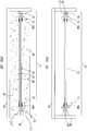
- post-tensioning tendon 11 may be positioned within concrete form 21.
- Concrete form 21 is a form into which concrete may be poured to form concrete member 40.
- Post-tensioning tendon 11 may include for example and without limitation fixed end anchor 13, tension member 15, and stressing end anchor 17.
- fixed end anchor 13 may include fixed end anchor body 14.
- Fixed-end anchor body 14 may be positioned within concrete form 21 such that fixed-end anchor body 14 will be encased in concrete 23 after concrete is poured into concrete form 21.
- fixed end cap 19 may be positioned at distal end 41 of fixed end anchor body 14. Fixed end cap 19 may, in certain embodiments, protect tension member 15 from corrosion after concrete 23 is poured by preventing or retarding corrosive or reactive fluids or concrete from contacting tension member 15.
- Stressing end anchor 17 may be positioned within concrete form 21 such that it is substantially surrounded by concrete 23.
- Pocket former 25 may be positioned between stressing end anchor body 18 and end wall 22 of concrete form 21.
- Pocket former 25 may be adapted to, for example and without limitation, prevent or restrict concrete 23 from filling the space between stressing end anchor body 18 and end wall 22, thus forming a cavity or pocket in edge 42 of concrete member 40 formed by concrete 23 within concrete form 21. Pocket former 25 may thus allow access to tension member 15 from outside concrete member 40 once concrete member 40 is sufficiently hardened and end wall 22 is removed.
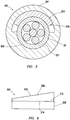
- the tension member 15 includes strand 27 and sheath 29.
- Strand 27 may be a single or multi-strand metal cable.
- Sheath 29 may be tubular or generally tubular and is positioned about strand 27. In some embodiments, space between strand 27 and sheath 29 may be filled or partially filled with a filler such as grease.
- a length of sheath 29 may be removed from first end 43 of tension member 15, exposing strand 27.
- Strand 27 is inserted through fixed end anchor 13 until sheath 29 engages with sheathing retention capsule 100.
- Strand 27 may then be coupled to fixed end anchor 13 such as by the use of wedges.
- Tension member 15 may be positioned within concrete form 21 and tension member 15 may be cut to correspond with the length of concrete form 21.
- a length of sheath 29 may be removed from second end 44 of tension member 15, exposing strand 27.
- Strand 27 is inserted through stressing end anchor 17 until sheath 29 engages with sheathing retention capsule 100 within stressing end anchor 17.
- sheathing retention assembly 100 includes outer cap 101, one or more holding elements 103, and seal 119.
- Outer cap 101 may be tubular or generally tubular.
- Outer cap 101 may include a coupler for connecting to tubular extension 14 of stressing end anchor 17 through which tension member 15 may pass.
- sheathing assembly 100 may be used in conjunction with fixed end anchor 13, as shown in FIG. 2B .
- tubular extension 14 may be formed integrally with stressing end anchor 17.
- tubular extension 14 may be formed separately from stressing end anchor 17 and may be coupled thereto by, for example and without limitation, a press fit, chemical or mechanical welding, a thread, detent, press lock, bayonet, or tab-and-slot connection.
- Tubular extension 14 is coupled to outer cap 101 and may be coupled before tubular extension 14 is installed to stressing end anchor 17.
- outer cap 101 may be coupled in a non-actuated position when tubular extension 14 is coupled to outer cap 101. In the non-actuated position, holding elements are positioned within outer cap 101 and the wedges may slide along sheath 29.
- FIG. 5 A depicts outer cap 101 in non-actuated position.
- Outer cap 101 may be moved into the actuated position by coupling to tubular extension 14 by a coupler, including for example and without limitation a thread, detent, press lock, bayonet, or tab-and-slot connection.
- a coupler including for example and without limitation a thread, detent, press lock, bayonet, or tab-and-slot connection.
- FIGs. 2A , 2B depict outer cap 101 in an actuated position.
- the coupler is a tab-and-slot connection where outer cap 101 may include one or more slots 102 that may receive one or more corresponding tabs 104 formed on engaging surface 135 of tubular extension 14.
- tabs 102 may be wedge-shaped to allow installation of outer cap 101 about tubular extension 14 while inhibiting removal of extension 14 therefrom.
- outer cap 301 may include outer cap bayonet ramps 302. Outer cap bayonet ramps 302 may interconnect with corresponding tubular extension bayonet ramps 304 formed on tubular extension 14. Outer cap 101 may couple to tubular extension 14 through one or more intermediate components without deviating from the scope of this disclosure. In some embodiments, as depicted in FIG. 2 , outer cap 101 may include a tapered inner surface defined herein as forcing surface 115.
- Holding elements 103 are positioned at least partially within outer cap 101.
- Holding elements 103 may be wedge shaped.
- Holding elements 103 include tapered surfaces that collectively form tapered outer surface 117. Tapered outer surface 117 abuts and corresponds with forcing surface 115.
- Holding elements 103 may be spaced apart within sheathing retention assembly 100 or may be placed in abutment. Holding elements 103 are positioned within sheathing retention assembly 100 such that tapered outer surface 117 abuts forcing surface 115.
- Forcing surface 115 and outer surface 117 of holding elements 103 is positioned such that as outer cap 101 is installed in the actuated position onto tubular extension 14, the taper of forcing surface 115 and the taper of the outer surface 117 of holding elements 103 serves to bias or push holding elements 103 inward into contact with sheath 29, thus, in some embodiments, increasing normal force between holding elements 103 and sheath 29.
- Inner surfaces 120 of holding elements 103 may collectively form inner face 109.
- Inner face 109 may be continuous or discontinuous depending on the specific arrangement of holding elements 103.
- Inner face 109 may have inner face diameter 122 generally corresponding with, i.e., approximately equal to, outer diameter 124 of sheath 29.
- holding elements 103 may include one or more surface features on inner face 109 that may increase the static friction between the outer surface 126 of sheath 29 and holding elements 103.
- the surface features may include, for example and without limitation, teeth 111.
- Teeth 111 may be one or more grooves, protrusions, or ridges that contact outer surface 126 of sheath 29 and, in some embodiments, press into outer surface 126 of sheath 29, thus increasing the retention force between holding elements 103 and sheath 29.
- sheathing retention assembly 100 may also include seal 119.
- Seal 119 may be positioned to seal between sheath 29 and tubular extension 14 and may further be positioned between outer cap 101 and holding elements 103. Seal 119 may be annular or generally annular and fit into recess 128 formed between outer cap 101, tubular extension 14, and sheath 29. In some embodiments, seal 119 may be positioned such that as outer cap 101 is installed into the actuated position onto tubular extension 14, seal 119 is compressed between tubular extension 14, sheath 29, and outer cap 101. Seal 119 may protect tension member 15 from corrosion after concrete 23 (shown in FIG. 1B ) is poured, such as by inhibiting fluid ingress into the interior of sheath 29. Additionally, seal 119 may inhibit concrete 23 from entering tension member 15. In some embodiments, seal 119 may form a press fit with outer cap 101. In some such embodiments, seal 119 may retain holding elements 103 within outer cap 101 prior to installation thereof.
- holding element 203 of sheathing retention assembly 200 may be positioned about only a portion of sheath 29.
- holding element 203 may be a single wedge 206.
- Wedge 206 may press against sheath 29 when compressed.
- outer body 201 may include holding surface 202 positioned in opposition to wedge 206 to provide an opposing force on sheath 29 as wedge 206 engages sheath 29.
- one or more holding elements 103 may be formed as one or more wedges 106 as depicted in FIG. 4A .
- At least one wedge 106 may be arcuate.
- wedges 106 may include partial split 108 to allow wedge 106 to flex as depicted in FIG. 4B when compressed. Partial split 108 may extend from first end 140 of wedge 106 but not to second end 142 of wedge 106. This flexure may allow for deformation of wedge 106, and increased contact of wedge 106 with sheath 29.
- the inner diameter of wedge 106 may be less than outer diameter 124 of sheath 29 to allow for a friction fit or press fit. The inner diameter of wedge 106 is the inner diameter of wedge 106 were it to extend circumferentially.
- Split 108 may allow deformation of wedge 106 to allow the inner diameter of wedge 106 thereof to more closely match outer diameter 124 of sheath 29.
- sheathing retention assembly 300 may further include spacing collet 321.
- Spacing collet 321 may be positioned at least partially within outer cap 301.
- Spacing collet 321 may be tubular or generally tubular and may form a friction fit with the outer surface 126 of sheath 29.
- Spacing collet 321 may be positioned to fit within flanges 323 formed on holding elements 303. Spacing collet 321 may thus retain holding elements 303 in an open position while sheath 29 is installed into sheathing retention assembly 300, allowing sheath 29 to more easily move through holding elements 303 until outer cap 301 is installed to tubular extension 14.
- seal 319 may include spacing flange 325 adapted to fit into end flanges 327 formed on holding elements 303. Seal 319 may thus retain holding elements 303 in an open position until outer cap 301 is installed to tubular extension 14. Furthermore, inward movement of holding elements 303 may cause spacing flange 325 to contact outer surface 126 of sheath 29.
- holding element 303 may be formed from a plurality of pieces.
- holding element 303 may include wedged piece 306 and die face piece 308.
- Wedged piece 306 may have tapered outer surface 310 and flat inner surface 312, where outer surface 314 of die face piece 308 may be flat.
- wedged piece 306 may be bonded to die face 308.
- sheath retention assembly 100 may be coupled to fixed end anchor 13 before fixed end anchor 13 is positioned within concrete form 21 as depicted in FIG. 1A when tension member 15 is preinstalled into fixed end anchor 13.
- a second sheath retention assembly 100 is positioned about tension member 15 before tension member 15 is passed through stressing end anchor 17.
- Tension member 15 may be passed through stressing end anchor 17.
- Outer cap 101 is coupled to tubular extension 14 of stressing end anchor 17, causing holding elements 103 to engage outer surface 126 of sheath 29, retaining sheath 29 to stressing end anchor 17.
- seal 119 may also seal between at least outer surface 126 of sheath 29 and tubular extension 14. Contraction of sheath 29 may allow holding elements 103 to engage forcing surface 115, increasing the normal force between holding elements 103 and sheath 29, thus increasing the friction therebetween.
- sheathing retention assembly 100 may be utilized with any anchor for a post-tensioned concrete member including a fixed end anchor or stressing end anchor. Furthermore, sheathing retention assembly 100 may be used with an intermediate anchor as understood in the art.
Claims (14)
- Toron de post-tension (11), comprenant :
un élément de tension (15) comprenant un fil (27) et une gaine (29), la gaine (29) ayant une surface extérieure (126) ; un ancrage (13, 17) accouplé à une extrémité de l'élément de tension (15), l'ancrage (13, 17) comprenant une extension tubulaire (14) par laquelle l'élément de tension (15) est passé ; et un ensemble de retenue de gainage (100, 200, 300) comprenant : un chapeau extérieur (101, 301), le chapeau extérieur (101, 301) ayant une surface d'effort conique (115), le chapeau extérieur (101, 301) étant accouplé à l'extension tubulaire (14) ; et un ou plusieurs éléments de maintien (103, 203, 303) positionnés au moins en partie dans le chapeau extérieur (101, 301), le ou les éléments de maintien (103, 203, 303) ayant chacun une surface extérieure conique (117), en butée contre la surface d'effort conique (115), le ou les éléments de maintien (103, 203, 303) comprenant chacun une surface intérieure (120) qui vient en contact avec la surface extérieure (126) de la gaine (29), le toron de post-tension étant caractérisé en ce que, quand le chapeau extérieur (101, 301) est installé dans la position active sur l'extension tubulaire (14), le cône de la surface d'effort (115) et le cône de la surface extérieure (117) des éléments de maintien (103, 203, 303) servent à pousser ou solliciter les éléments de maintien (103, 203, 303) vers l'intérieur en contact avec la gaine (29). - Toron de post-tension (11) selon la revendication 1, comportant une pluralité d'éléments de maintien (103, 203, 303), les surfaces intérieures (120) de la pluralité d'éléments de maintien (103, 203, 303) formant une face intérieure (109) ; éventuellement, la face intérieure (109) comprenant des dents, les dents de la face intérieure (109) étant en contact avec la surface extérieure (126) de la gaine (29).
- Toron de post-tension (11) selon l'une quelconque des revendications 1 et 2, dans lequel le chapeau extérieur (101, 301) s'accouple à l'extension tubulaire (14) par un moyen d'accouplement sélectionné dans le groupe constitué d'un moyen d'accouplement par filetage, par encliquetage, par verrouillage par pression, à baïonnette ou par languette et fente.
- Toron de post-tension (11) selon la revendication 3, dans lequel :
l'extension tubulaire (14) a une surface de contact (135), le moyen d'accouplement étant un moyen d'accouplement par languette et fente, le moyen d'accouplement par languette et fente comprenant : une ou plusieurs fentes (102) formées dans le chapeau extérieur (101) ; et une ou plusieurs languettes (104) formées sur une surface de contact (135) de l'extension tubulaire (14), la ou les fentes (102) recevant la ou les languettes (104) ; et/ou le moyen d'accouplement étant un moyen d'accouplement à baïonnette, le moyen d'accouplement à baïonnette comprenant : une ou plusieurs rampes de baïonnette de chapeau extérieur (302) positionnées sur le chapeau extérieur (301) ; et une ou plusieurs rampes d'extension tubulaire (304) positionnées sur l'extension tubulaire (14), les rampes de baïonnette de chapeau extérieur (302) s'interconnectant avec la ou les rampes de baïonnette d'extension tubulaire (304). - Toron de post-tension (11) selon l'une quelconque des revendications 1 à 4, comprenant en outre un joint (119, 319), le joint (119, 319) étant positionné dans le chapeau extérieur (101, 301), le joint (119, 319) étant positionné entre la surface extérieure (126) de la gaine (29) et l'extension tubulaire (14).
- Toron de post-tension (11) selon l'une quelconque des revendications 1 à 5, dans lequel le ou les éléments de maintien (103, 203, 303) sont des coins arqués (206).
- Toron de post-tension (11) selon l'une quelconque des revendications 1 à 6, dans lequel les coins arqués comprenant une fente partielle (108).
- Toron de post-tension (11) selon l'une quelconque des revendications 1 à 7, dans lequel chacun du ou des éléments de maintien (303) comprend en outre une bride (323), l'ensemble de retenu de gainage (300) comprenant en outre une bague d'espacement (321), la bague d'espacement (321) étant positionnée dans le chapeau extérieur (301) et positionnée pour s'ajuster dans les brides (323) du ou des éléments de maintien (303).
- Toron de post-tension (11) selon l'une quelconque des revendications 1 à 8, dans lequel au moins un du ou des éléments de maintien (303) est un coin, l'au moins un élément de maintien (303) comprenant une pièce en coin (306) et une pièce de face de matrice (308), la pièce en coin (306) ayant une surface extérieure conique (310) et une surface intérieure plane (312), la pièce de face de matrice (308) ayant une partie extérieure plane, la pièce en coin (306) et la pièce de face de matrice (308) étant soudées.
- Procédé d'accouplement d'un élément de tension (15) à un ancrage pour former un toron de post-tension (11), le procédé consistant à :
apporter l'élément de tension (15), l'élément de tension (15) comprenant un fil (27) et une gaine (29), la gaine (29) ayant une surface extérieure (126) ; apporter l'ancrage (13, 17), l'ancrage (13, 17) comprenant une extension tubulaire (14) ; positionner un chapeau extérieur (101, 301) autour d'une extension tubulaire (14) dans une position non active, le chapeau extérieur (101, 301) ayant une surface d'effort conique (115) ; accoupler le chapeau extérieur (101, 301) à l'extension tubulaire (14), de manière à déplacer le chapeau extérieur (101, 301) dans une position active ; positionner un ou plusieurs éléments de maintien (103, 203, 303) au moins en partie dans le chapeau extérieur (101, 301), le ou les éléments de maintien (103, 203, 303) ayant chacun une surface extérieure conique (117), en butée contre la surface d'effort conique (115), le ou les éléments de maintien (103, 203, 303) comprenant chacun une surface intérieure (120) qui vient en contact avec la surface extérieure (126) de la gaine (29) ; faire passer l'extrémité de l'élément de tension (15) par l'extension tubulaire (14) ; accoupler le chapeau extérieur (101, 301) à l'extension tubulaire (14) ; le procédé étant caractérisé par l'étape consistant à installer le chapeau extérieur (101, 301) dans la position active sur l'extension tubulaire (14), de sorte que le cône de la surface d'effort (115) et le cône de la surface extérieure (117) des éléments de maintien (103, 203, 303) servent à pousser ou solliciter les éléments de maintien (103, 203, 303) vers l'intérieur en contact avec la gaine (29). - Procédé selon la revendication 10, comprenant en outre les étapes consistant à :
appliquer une force de traction à la gaine (29), de manière à mettre en contact le ou les éléments de maintien (103, 203, 303) avec la surface d'effort (115) ; et/ou positionner un joint (119, 319) dans le chapeau extérieur (101, 301) et positionner en outre le joint (119, 319) entre la surface extérieure (126) de la gaine (29) et l'extension tubulaire (14). - Procédé selon la revendication 10 ou 11, dans lequel :
l'ensemble de retenu de gainage (200) comprend un unique élément de maintien (203), l'unique élément de maintien (203) étant un unique coin (206), et le procédé consistant en outre à : positionner l'unique coin (206) uniquement autour d'une partie de la gaine (29) ; positionner une surface de maintien (202) en opposition à l'unique coin (206) ; et presser l'unique coin (206) contre la gaine (29). - Procédé selon l'une quelconque des revendications 10 à 12, consistant en outre à :
positionner une bague d'espacement (321) au moins en partie dans le chapeau extérieur (301) ; et former un ajustement serré entre la bague d'espacement (321) et la surface extérieure (126) de la gaine (29). - Procédé selon la revendication 10 ou 11, dans lequel chacun du ou des éléments de maintien (103, 203, 303) est un coin, chaque coin comprenant une fente partielle (108), et le procédé consistant en outre à : presser le ou les coins pour faire fléchir le ou les coins, de manière à augmenter un contact entre le coin et la gaine (29).
Applications Claiming Priority (3)
| Application Number | Priority Date | Filing Date | Title |
|---|---|---|---|
| US201562200975P | 2015-08-04 | 2015-08-04 | |
| PCT/US2016/045174 WO2017023940A1 (fr) | 2015-08-04 | 2016-08-02 | Capuchon d'extrémité de verrouillage de revêtement |
| US15/226,594 US10145114B2 (en) | 2015-08-04 | 2016-08-02 | Sheathing lock end cap |
Publications (2)
| Publication Number | Publication Date |
|---|---|
| EP3128093A1 EP3128093A1 (fr) | 2017-02-08 |
| EP3128093B1 true EP3128093B1 (fr) | 2019-11-20 |
Family
ID=56571191
Family Applications (1)
| Application Number | Title | Priority Date | Filing Date |
|---|---|---|---|
| EP16182581.5A Active EP3128093B1 (fr) | 2015-08-04 | 2016-08-03 | Élément de béton précontraint et méthode d'assamblage d'un élément de tension |
Country Status (1)
| Country | Link |
|---|---|
| EP (1) | EP3128093B1 (fr) |
Family Cites Families (4)
| Publication number | Priority date | Publication date | Assignee | Title |
|---|---|---|---|---|
| US4773198A (en) * | 1986-09-05 | 1988-09-27 | Continental Concrete Structures, Inc. | Post-tensioning anchorages for aggressive environments |
| US20020007604A1 (en) * | 2000-07-21 | 2002-01-24 | Wallstein Alexander I. | Intermediate anchorage for concrete structures |
| US6381912B1 (en) * | 2000-12-29 | 2002-05-07 | Felix L. Sorkin | Apparatus and method for sealing an intermediate anchor of a post-tension anchor system |
| EP1373644B1 (fr) * | 2001-03-23 | 2013-01-09 | Samwoo Geotech.Co | Ensamble clavette et ancrage interne utilisant cette clavette |
-
2016
- 2016-08-03 EP EP16182581.5A patent/EP3128093B1/fr active Active
Non-Patent Citations (1)
| Title |
|---|
| None * |
Also Published As
| Publication number | Publication date |
|---|---|
| EP3128093A1 (fr) | 2017-02-08 |
Similar Documents
| Publication | Publication Date | Title |
|---|---|---|
| US10428523B2 (en) | Sheathing lock end cap | |
| US10113313B2 (en) | Sheathing retention capsule | |
| US9896845B2 (en) | Spindle lock anchor for post tensioned concrete member | |
| EP3269894A1 (fr) | Dispositif d'accouplement encapsulé | |
| EP3882413A1 (fr) | Système d'ancrage de béton intermédiaire doté d'un couvercle | |
| CA2952688A1 (fr) | Ancrage | |
| US20230040105A1 (en) | Multi-anchor concrete post-tensioning system | |
| US9869091B2 (en) | Pocket cap for post-tensioned concrete member | |
| EP3128093B1 (fr) | Élément de béton précontraint et méthode d'assamblage d'un élément de tension | |
| US10343354B2 (en) | Collapsible element pocket former | |
| EP3317471B1 (fr) | Ensemble d'ancrage pour une structure, structure en béton comprenant un tel ensemble, et procédé de fabrication d'une telle structure en béton | |
| EP3128094B1 (fr) | Systéme d'ancrage et procédé d'accouplement d'un élément de tension | |
| EP3128095B1 (fr) | Tirant de precontrainte par post-tension et procede de couplage | |
| EP3128092B1 (fr) | Procede de formation d'un element de beton precontraint | |
| EP3375949B1 (fr) | Systeme pour élément de béton précontraint | |
| EP3744925A1 (fr) | Appareil pour réparer un élément de tension |
Legal Events
| Date | Code | Title | Description |
|---|---|---|---|
| PUAI | Public reference made under article 153(3) epc to a published international application that has entered the european phase |
Free format text: ORIGINAL CODE: 0009012 |
|
| STAA | Information on the status of an ep patent application or granted ep patent |
Free format text: STATUS: THE APPLICATION HAS BEEN PUBLISHED |
|
| AK | Designated contracting states |
Kind code of ref document: A1 Designated state(s): AL AT BE BG CH CY CZ DE DK EE ES FI FR GB GR HR HU IE IS IT LI LT LU LV MC MK MT NL NO PL PT RO RS SE SI SK SM TR |
|
| AX | Request for extension of the european patent |
Extension state: BA ME |
|
| STAA | Information on the status of an ep patent application or granted ep patent |
Free format text: STATUS: REQUEST FOR EXAMINATION WAS MADE |
|
| 17P | Request for examination filed |
Effective date: 20170622 |
|
| RBV | Designated contracting states (corrected) |
Designated state(s): AL AT BE BG CH CY CZ DE DK EE ES FI FR GB GR HR HU IE IS IT LI LT LU LV MC MK MT NL NO PL PT RO RS SE SI SK SM TR |
|
| STAA | Information on the status of an ep patent application or granted ep patent |
Free format text: STATUS: EXAMINATION IS IN PROGRESS |
|
| 17Q | First examination report despatched |
Effective date: 20180115 |
|
| GRAP | Despatch of communication of intention to grant a patent |
Free format text: ORIGINAL CODE: EPIDOSNIGR1 |
|
| STAA | Information on the status of an ep patent application or granted ep patent |
Free format text: STATUS: GRANT OF PATENT IS INTENDED |
|
| INTG | Intention to grant announced |
Effective date: 20190607 |
|
| GRAS | Grant fee paid |
Free format text: ORIGINAL CODE: EPIDOSNIGR3 |
|
| GRAA | (expected) grant |
Free format text: ORIGINAL CODE: 0009210 |
|
| STAA | Information on the status of an ep patent application or granted ep patent |
Free format text: STATUS: THE PATENT HAS BEEN GRANTED |
|
| AK | Designated contracting states |
Kind code of ref document: B1 Designated state(s): AL AT BE BG CH CY CZ DE DK EE ES FI FR GB GR HR HU IE IS IT LI LT LU LV MC MK MT NL NO PL PT RO RS SE SI SK SM TR |
|
| REG | Reference to a national code |
Ref country code: GB Ref legal event code: FG4D |
|
| REG | Reference to a national code |
Ref country code: CH Ref legal event code: EP |
|
| REG | Reference to a national code |
Ref country code: IE Ref legal event code: FG4D |
|
| REG | Reference to a national code |
Ref country code: DE Ref legal event code: R096 Ref document number: 602016024563 Country of ref document: DE |
|
| REG | Reference to a national code |
Ref country code: AT Ref legal event code: REF Ref document number: 1204345 Country of ref document: AT Kind code of ref document: T Effective date: 20191215 |
|
| REG | Reference to a national code |
Ref country code: NL Ref legal event code: MP Effective date: 20191120 |
|
| REG | Reference to a national code |
Ref country code: LT Ref legal event code: MG4D |
|
| PG25 | Lapsed in a contracting state [announced via postgrant information from national office to epo] |
Ref country code: NL Free format text: LAPSE BECAUSE OF FAILURE TO SUBMIT A TRANSLATION OF THE DESCRIPTION OR TO PAY THE FEE WITHIN THE PRESCRIBED TIME-LIMIT Effective date: 20191120 Ref country code: LT Free format text: LAPSE BECAUSE OF FAILURE TO SUBMIT A TRANSLATION OF THE DESCRIPTION OR TO PAY THE FEE WITHIN THE PRESCRIBED TIME-LIMIT Effective date: 20191120 Ref country code: GR Free format text: LAPSE BECAUSE OF FAILURE TO SUBMIT A TRANSLATION OF THE DESCRIPTION OR TO PAY THE FEE WITHIN THE PRESCRIBED TIME-LIMIT Effective date: 20200221 Ref country code: NO Free format text: LAPSE BECAUSE OF FAILURE TO SUBMIT A TRANSLATION OF THE DESCRIPTION OR TO PAY THE FEE WITHIN THE PRESCRIBED TIME-LIMIT Effective date: 20200220 Ref country code: SE Free format text: LAPSE BECAUSE OF FAILURE TO SUBMIT A TRANSLATION OF THE DESCRIPTION OR TO PAY THE FEE WITHIN THE PRESCRIBED TIME-LIMIT Effective date: 20191120 Ref country code: LV Free format text: LAPSE BECAUSE OF FAILURE TO SUBMIT A TRANSLATION OF THE DESCRIPTION OR TO PAY THE FEE WITHIN THE PRESCRIBED TIME-LIMIT Effective date: 20191120 Ref country code: FI Free format text: LAPSE BECAUSE OF FAILURE TO SUBMIT A TRANSLATION OF THE DESCRIPTION OR TO PAY THE FEE WITHIN THE PRESCRIBED TIME-LIMIT Effective date: 20191120 Ref country code: BG Free format text: LAPSE BECAUSE OF FAILURE TO SUBMIT A TRANSLATION OF THE DESCRIPTION OR TO PAY THE FEE WITHIN THE PRESCRIBED TIME-LIMIT Effective date: 20200220 |
|
| REG | Reference to a national code |
Ref country code: ES Ref legal event code: FG2A Ref document number: 2762871 Country of ref document: ES Kind code of ref document: T3 Effective date: 20200526 |
|
| PG25 | Lapsed in a contracting state [announced via postgrant information from national office to epo] |
Ref country code: RS Free format text: LAPSE BECAUSE OF FAILURE TO SUBMIT A TRANSLATION OF THE DESCRIPTION OR TO PAY THE FEE WITHIN THE PRESCRIBED TIME-LIMIT Effective date: 20191120 Ref country code: IS Free format text: LAPSE BECAUSE OF FAILURE TO SUBMIT A TRANSLATION OF THE DESCRIPTION OR TO PAY THE FEE WITHIN THE PRESCRIBED TIME-LIMIT Effective date: 20200320 Ref country code: HR Free format text: LAPSE BECAUSE OF FAILURE TO SUBMIT A TRANSLATION OF THE DESCRIPTION OR TO PAY THE FEE WITHIN THE PRESCRIBED TIME-LIMIT Effective date: 20191120 |
|
| PG25 | Lapsed in a contracting state [announced via postgrant information from national office to epo] |
Ref country code: AL Free format text: LAPSE BECAUSE OF FAILURE TO SUBMIT A TRANSLATION OF THE DESCRIPTION OR TO PAY THE FEE WITHIN THE PRESCRIBED TIME-LIMIT Effective date: 20191120 |
|
| PG25 | Lapsed in a contracting state [announced via postgrant information from national office to epo] |
Ref country code: EE Free format text: LAPSE BECAUSE OF FAILURE TO SUBMIT A TRANSLATION OF THE DESCRIPTION OR TO PAY THE FEE WITHIN THE PRESCRIBED TIME-LIMIT Effective date: 20191120 Ref country code: PT Free format text: LAPSE BECAUSE OF FAILURE TO SUBMIT A TRANSLATION OF THE DESCRIPTION OR TO PAY THE FEE WITHIN THE PRESCRIBED TIME-LIMIT Effective date: 20200412 Ref country code: DK Free format text: LAPSE BECAUSE OF FAILURE TO SUBMIT A TRANSLATION OF THE DESCRIPTION OR TO PAY THE FEE WITHIN THE PRESCRIBED TIME-LIMIT Effective date: 20191120 Ref country code: RO Free format text: LAPSE BECAUSE OF FAILURE TO SUBMIT A TRANSLATION OF THE DESCRIPTION OR TO PAY THE FEE WITHIN THE PRESCRIBED TIME-LIMIT Effective date: 20191120 Ref country code: CZ Free format text: LAPSE BECAUSE OF FAILURE TO SUBMIT A TRANSLATION OF THE DESCRIPTION OR TO PAY THE FEE WITHIN THE PRESCRIBED TIME-LIMIT Effective date: 20191120 |
|
| REG | Reference to a national code |
Ref country code: AT Ref legal event code: MK05 Ref document number: 1204345 Country of ref document: AT Kind code of ref document: T Effective date: 20191120 |
|
| REG | Reference to a national code |
Ref country code: DE Ref legal event code: R097 Ref document number: 602016024563 Country of ref document: DE |
|
| PG25 | Lapsed in a contracting state [announced via postgrant information from national office to epo] |
Ref country code: SM Free format text: LAPSE BECAUSE OF FAILURE TO SUBMIT A TRANSLATION OF THE DESCRIPTION OR TO PAY THE FEE WITHIN THE PRESCRIBED TIME-LIMIT Effective date: 20191120 Ref country code: SK Free format text: LAPSE BECAUSE OF FAILURE TO SUBMIT A TRANSLATION OF THE DESCRIPTION OR TO PAY THE FEE WITHIN THE PRESCRIBED TIME-LIMIT Effective date: 20191120 |
|
| PLBE | No opposition filed within time limit |
Free format text: ORIGINAL CODE: 0009261 |
|
| STAA | Information on the status of an ep patent application or granted ep patent |
Free format text: STATUS: NO OPPOSITION FILED WITHIN TIME LIMIT |
|
| 26N | No opposition filed |
Effective date: 20200821 |
|
| PG25 | Lapsed in a contracting state [announced via postgrant information from national office to epo] |
Ref country code: SI Free format text: LAPSE BECAUSE OF FAILURE TO SUBMIT A TRANSLATION OF THE DESCRIPTION OR TO PAY THE FEE WITHIN THE PRESCRIBED TIME-LIMIT Effective date: 20191120 Ref country code: PL Free format text: LAPSE BECAUSE OF FAILURE TO SUBMIT A TRANSLATION OF THE DESCRIPTION OR TO PAY THE FEE WITHIN THE PRESCRIBED TIME-LIMIT Effective date: 20191120 Ref country code: AT Free format text: LAPSE BECAUSE OF FAILURE TO SUBMIT A TRANSLATION OF THE DESCRIPTION OR TO PAY THE FEE WITHIN THE PRESCRIBED TIME-LIMIT Effective date: 20191120 |
|
| PG25 | Lapsed in a contracting state [announced via postgrant information from national office to epo] |
Ref country code: MC Free format text: LAPSE BECAUSE OF FAILURE TO SUBMIT A TRANSLATION OF THE DESCRIPTION OR TO PAY THE FEE WITHIN THE PRESCRIBED TIME-LIMIT Effective date: 20191120 |
|
| REG | Reference to a national code |
Ref country code: CH Ref legal event code: PL |
|
| PG25 | Lapsed in a contracting state [announced via postgrant information from national office to epo] |
Ref country code: LU Free format text: LAPSE BECAUSE OF NON-PAYMENT OF DUE FEES Effective date: 20200803 Ref country code: LI Free format text: LAPSE BECAUSE OF NON-PAYMENT OF DUE FEES Effective date: 20200831 Ref country code: CH Free format text: LAPSE BECAUSE OF NON-PAYMENT OF DUE FEES Effective date: 20200831 |
|
| REG | Reference to a national code |
Ref country code: BE Ref legal event code: MM Effective date: 20200831 |
|
| PG25 | Lapsed in a contracting state [announced via postgrant information from national office to epo] |
Ref country code: BE Free format text: LAPSE BECAUSE OF NON-PAYMENT OF DUE FEES Effective date: 20200831 Ref country code: IE Free format text: LAPSE BECAUSE OF NON-PAYMENT OF DUE FEES Effective date: 20200803 |
|
| PG25 | Lapsed in a contracting state [announced via postgrant information from national office to epo] |
Ref country code: TR Free format text: LAPSE BECAUSE OF FAILURE TO SUBMIT A TRANSLATION OF THE DESCRIPTION OR TO PAY THE FEE WITHIN THE PRESCRIBED TIME-LIMIT Effective date: 20191120 Ref country code: MT Free format text: LAPSE BECAUSE OF FAILURE TO SUBMIT A TRANSLATION OF THE DESCRIPTION OR TO PAY THE FEE WITHIN THE PRESCRIBED TIME-LIMIT Effective date: 20191120 Ref country code: CY Free format text: LAPSE BECAUSE OF FAILURE TO SUBMIT A TRANSLATION OF THE DESCRIPTION OR TO PAY THE FEE WITHIN THE PRESCRIBED TIME-LIMIT Effective date: 20191120 |
|
| PG25 | Lapsed in a contracting state [announced via postgrant information from national office to epo] |
Ref country code: MK Free format text: LAPSE BECAUSE OF FAILURE TO SUBMIT A TRANSLATION OF THE DESCRIPTION OR TO PAY THE FEE WITHIN THE PRESCRIBED TIME-LIMIT Effective date: 20191120 |
|
| P01 | Opt-out of the competence of the unified patent court (upc) registered |
Effective date: 20230613 |
|
| PGFP | Annual fee paid to national office [announced via postgrant information from national office to epo] |
Ref country code: IT Payment date: 20230828 Year of fee payment: 8 Ref country code: GB Payment date: 20230830 Year of fee payment: 8 Ref country code: ES Payment date: 20230913 Year of fee payment: 8 |
|
| PGFP | Annual fee paid to national office [announced via postgrant information from national office to epo] |
Ref country code: FR Payment date: 20230830 Year of fee payment: 8 Ref country code: DE Payment date: 20230829 Year of fee payment: 8 |