EP3127730A1 - Vehicle door with front and rear parts opening in opposite directions and electric vehicle having same - Google Patents
Vehicle door with front and rear parts opening in opposite directions and electric vehicle having same Download PDFInfo
- Publication number
- EP3127730A1 EP3127730A1 EP14887744.2A EP14887744A EP3127730A1 EP 3127730 A1 EP3127730 A1 EP 3127730A1 EP 14887744 A EP14887744 A EP 14887744A EP 3127730 A1 EP3127730 A1 EP 3127730A1
- Authority
- EP
- European Patent Office
- Prior art keywords
- door
- compartment door
- compartment
- vehicle body
- hinge
- Prior art date
- Legal status (The legal status is an assumption and is not a legal conclusion. Google has not performed a legal analysis and makes no representation as to the accuracy of the status listed.)
- Granted
Links
- 230000007246 mechanism Effects 0.000 claims abstract description 32
- 239000011521 glass Substances 0.000 claims description 4
- 229910021419 crystalline silicon Inorganic materials 0.000 claims description 3
- 238000005516 engineering process Methods 0.000 description 3
- 238000000034 method Methods 0.000 description 3
- 230000018109 developmental process Effects 0.000 description 2
- 206010063493 Premature ageing Diseases 0.000 description 1
- 208000032038 Premature aging Diseases 0.000 description 1
- 238000004378 air conditioning Methods 0.000 description 1
- 239000011248 coating agent Substances 0.000 description 1
- 238000000576 coating method Methods 0.000 description 1
- 230000006872 improvement Effects 0.000 description 1
- 238000009413 insulation Methods 0.000 description 1
- 238000004519 manufacturing process Methods 0.000 description 1
- 239000002184 metal Substances 0.000 description 1
- 230000004048 modification Effects 0.000 description 1
- 238000012986 modification Methods 0.000 description 1
- 230000008569 process Effects 0.000 description 1
- 239000013589 supplement Substances 0.000 description 1
- 239000012780 transparent material Substances 0.000 description 1
- 238000009423 ventilation Methods 0.000 description 1
- 238000003466 welding Methods 0.000 description 1
Images




Classifications
-
- B—PERFORMING OPERATIONS; TRANSPORTING
- B60—VEHICLES IN GENERAL
- B60J—WINDOWS, WINDSCREENS, NON-FIXED ROOFS, DOORS, OR SIMILAR DEVICES FOR VEHICLES; REMOVABLE EXTERNAL PROTECTIVE COVERINGS SPECIALLY ADAPTED FOR VEHICLES
- B60J5/00—Doors
- B60J5/04—Doors arranged at the vehicle sides
- B60J5/047—Doors arranged at the vehicle sides characterised by the opening or closing movement
- B60J5/0472—Doors arranged at the vehicle sides characterised by the opening or closing movement the door having a hinge axis in horizontal direction transverse to vehicle longitudinal axis
-
- B—PERFORMING OPERATIONS; TRANSPORTING
- B60—VEHICLES IN GENERAL
- B60J—WINDOWS, WINDSCREENS, NON-FIXED ROOFS, DOORS, OR SIMILAR DEVICES FOR VEHICLES; REMOVABLE EXTERNAL PROTECTIVE COVERINGS SPECIALLY ADAPTED FOR VEHICLES
- B60J1/00—Windows; Windscreens; Accessories therefor
- B60J1/08—Windows; Windscreens; Accessories therefor arranged at vehicle sides
- B60J1/12—Windows; Windscreens; Accessories therefor arranged at vehicle sides adjustable
-
- B—PERFORMING OPERATIONS; TRANSPORTING
- B60—VEHICLES IN GENERAL
- B60J—WINDOWS, WINDSCREENS, NON-FIXED ROOFS, DOORS, OR SIMILAR DEVICES FOR VEHICLES; REMOVABLE EXTERNAL PROTECTIVE COVERINGS SPECIALLY ADAPTED FOR VEHICLES
- B60J5/00—Doors
- B60J5/04—Doors arranged at the vehicle sides
- B60J5/047—Doors arranged at the vehicle sides characterised by the opening or closing movement
- B60J5/0477—Doors arranged at the vehicle sides characterised by the opening or closing movement with two doors opening in opposite direction
-
- B—PERFORMING OPERATIONS; TRANSPORTING
- B60—VEHICLES IN GENERAL
- B60J—WINDOWS, WINDSCREENS, NON-FIXED ROOFS, DOORS, OR SIMILAR DEVICES FOR VEHICLES; REMOVABLE EXTERNAL PROTECTIVE COVERINGS SPECIALLY ADAPTED FOR VEHICLES
- B60J5/00—Doors
- B60J5/04—Doors arranged at the vehicle sides
- B60J5/048—Doors arranged at the vehicle sides characterised by the material
-
- B—PERFORMING OPERATIONS; TRANSPORTING
- B60—VEHICLES IN GENERAL
- B60J—WINDOWS, WINDSCREENS, NON-FIXED ROOFS, DOORS, OR SIMILAR DEVICES FOR VEHICLES; REMOVABLE EXTERNAL PROTECTIVE COVERINGS SPECIALLY ADAPTED FOR VEHICLES
- B60J7/00—Non-fixed roofs; Roofs with movable panels, e.g. rotary sunroofs
- B60J7/08—Non-fixed roofs; Roofs with movable panels, e.g. rotary sunroofs of non-sliding type, i.e. movable or removable roofs or panels, e.g. let-down tops or roofs capable of being easily detached or of assuming a collapsed or inoperative position
- B60J7/16—Non-fixed roofs; Roofs with movable panels, e.g. rotary sunroofs of non-sliding type, i.e. movable or removable roofs or panels, e.g. let-down tops or roofs capable of being easily detached or of assuming a collapsed or inoperative position non-foldable and rigid, e.g. a one-piece hard-top or a single rigid roof panel
- B60J7/1628—Non-fixed roofs; Roofs with movable panels, e.g. rotary sunroofs of non-sliding type, i.e. movable or removable roofs or panels, e.g. let-down tops or roofs capable of being easily detached or of assuming a collapsed or inoperative position non-foldable and rigid, e.g. a one-piece hard-top or a single rigid roof panel for covering the passenger compartment
- B60J7/1635—Non-fixed roofs; Roofs with movable panels, e.g. rotary sunroofs of non-sliding type, i.e. movable or removable roofs or panels, e.g. let-down tops or roofs capable of being easily detached or of assuming a collapsed or inoperative position non-foldable and rigid, e.g. a one-piece hard-top or a single rigid roof panel for covering the passenger compartment of non-convertible vehicles
- B60J7/1657—Non-fixed roofs; Roofs with movable panels, e.g. rotary sunroofs of non-sliding type, i.e. movable or removable roofs or panels, e.g. let-down tops or roofs capable of being easily detached or of assuming a collapsed or inoperative position non-foldable and rigid, e.g. a one-piece hard-top or a single rigid roof panel for covering the passenger compartment of non-convertible vehicles at least a major part of the roof pivoting about a stationary axis
-
- B—PERFORMING OPERATIONS; TRANSPORTING
- B60—VEHICLES IN GENERAL
- B60Y—INDEXING SCHEME RELATING TO ASPECTS CROSS-CUTTING VEHICLE TECHNOLOGY
- B60Y2200/00—Type of vehicle
- B60Y2200/90—Vehicles comprising electric prime movers
- B60Y2200/91—Electric vehicles
Definitions
- the present invention relates to the field of electric vehicle technology, particularly to a front-and-rear split door and an electric vehicle having the same.
- openings are provided on two sides of the passenger compartment, the doors are mostly mounted on the sides of the vehicle body, the openings are covered by the front door and the rear door, such that the openings can be opened and closed
- a specific arrangement is as follows: the front portion of the front door is pivotally connected to the vehicle body via a hinge; and the front or rear of the rear door is pivotally connected to the vehicle body via the hinge.
- Frames are respectively disposed between the front door and a front windshield, and between the front doors and a rear windshield.
- the frame in the vehicle body will obstruct the driver's vision, which causes some blind spots affecting driving comfort and vision; and the roof and the doors are generally made of metal and therefore have large weight, thereby affecting the performance of the vehicle.
- the object of the present invention is to provide a front-and-rear split doors to resolve the problem existing the prior art that the driving vision is not wide enough.
- the present invention provides front-and-rear split door, used in an electric vehicle, comprising a vehicle body and a passenger compartment disposed on the vehicle body, wherein the front-and-rear split door comprises a front compartment door and a rear compartment door configured to open or close a passenger compartment, wherein the front compartment door and the rear compartment door are provided above the passenger compartment; a front end of the front compartment door is connected to a vehicle body via a first hinge assembly, a rear end of the rear compartment door is connected to the vehicle body via a second hinge assembly; and the electric vehicle further comprises a first turning mechanism configured to control the front compartment door to turn outwardly about the first hinge assembly and a second turning mechanism configured to control the rear compartment door to turn outwardly about the second hinge assembly.
- the front compartment door comprises a front cover and two front doors respectively connected to two sides of the front cover
- the rear compartment door comprises a rear cover and two rear doors respectively connected to two sides of the rear cover
- the electric vehicle further comprises a first linkage turning device configured to turn each of the front doors in a linkage manner when turned with front compartment door and a second linkage turning device configured to turn each of the rear doors in a linkage manner when turned with rear compartment door.
- the first linkage turning device comprises a third hinge assembly connected between the respective front door and the front cover and a third turning mechanism connected between the respective front door and the vehicle body and is configured to drive the respective front door to turn about the third hinge assembly when the front compartment door is turned;
- the second linkage turning device comprises a fourth hinge assembly connected between the respective rear door and the rear cover and a fourth turning mechanism connected between the respective rear door and the vehicle body and is configured to drive the respective rear door to turn about the third hinge assembly when the rear compartment door is turned.
- first hinge assembly comprises a first hinge base disposed on the vehicle body and a first hinge member with one end disposed in the first hinge base and rotatable oppositely with respect to the first hinge base, another end of the first hinge member is fixed to the front compartment door; and the second hinge assembly comprises a second hinge base disposed on the vehicle body and a second hinge member with one end disposed in the second hinge base and rotatable oppositely with respect to the second hinge base, another end of the second hinge member is fixed to the rear compartment door.
- the first turning mechanism comprises at least one first pneumatic strut with two ends respectively connected to the front compartment door and the vehicle body via universal joints and a first pump configured to fill high-pressure gas to the first pneumatic strut to allow the first pneumatic strut to drive the front compartment door to turn;
- the second turning mechanism comprises at least one second pneumatic strut with two ends respectively connected to the rear compartment door and the vehicle body via universal joints and a second pump configured to fill high-pressure gas to the second pneumatic strut to allow the second pneumatic strut to drive the rear compartment door to turn.
- the third hinge assembly comprises first fixing shafts disposed on two sides of the front cover and third hinge members each with one end sleeving the first fixing shaft and rotatable oppositely with respect to the first fixing shaft, the other end of the third hinge member is fixed to the front door;
- the fourth hinge assembly comprises second fixing shafts disposed on two sides of the rear cover and fourth hinge members each with one end sleeving the second fixing shaft and rotatable oppositely with respect to the second fixing shaft, the other end of the fourth hinge member is fixed to the rear door.
- the third turning mechanism comprises at least one pair of first air springs, two ends of each air spring are respectively connected to the respective front door and the vehicle body via universal joints;
- the fourth turning mechanism comprises at least one pair of second air springs, the vehicle body is provided with two longitudinal fixing columns on two sides, each of the second air springs is respectively connected to the respective rear door and a top end of the respective fixing column via universal joints.
- front compartment door and/or the rear compartment door is provided with a air window.
- front compartment door and/or the rear compartment door is provided with a handle.
- front compartment door and/or the rear compartment door is made of glass or transparent PC.
- At least a part of the front compartment door and/or the rear compartment door is made of crystalline silicon capable of absorbing sunlight.
- At least a part of the front compartment door and/or the rear compartment door is covered with a reflective PVC film.
- Another object of the present invention is to provide an electric vehicle comprising a vehicle body and a front-and-rear split door mentioned above, from front to rear, the vehicle body is provided with a front luggage compartment, a passenger compartment and a rear luggage compartment, the front-and-rear split door comprises the front compartment door connected to the front end of the passenger compartment and the rear compartment door connected to the rear end of the passenger compartment.
- the present invention provides a the electric vehicle with a front-and-rear door, the front compartment door and the rear compartment door are respectively driven by the first turning mechanism and the second turning mechanism, and can respectively turn about the first hinge assembly and the second hinge assembly to open or close the openings of the passenger compartment, there is no need to design an A pillar and a C pillar on the vehicle body, such that the driver can have a broader view, thereby improving the driving comfort, and the weight of the vehicle body will also be reduced, so that the vehicle performance is improved.
- the present invention provides a preferred embodiment.
- This embodiment provides a front-and-rear split door 9, used in an electric vehicle, comprising a vehicle body 1 and a passenger compartment 101 disposed on the vehicle body 1, wherein the front-and-rear split door comprises a front compartment door 901 and a rear compartment door 902 configured to open or close a passenger compartment 101, wherein the front compartment door 901 and the rear compartment door 902 are provided above the passenger compartment 101; a front end of the front compartment door 901 is connected to a vehicle body 1 via a first hinge assembly 903, a rear end of the rear compartment door 902 is connected to the vehicle body 1 via a second hinge assembly 904; and the electric vehicle further comprises a first turning mechanism 905 configured to control the front compartment door 901 to turn outwardly about the first hinge assembly 903 and a second turning mechanism 906 configured to control the rear compartment door 902 to turn outwardly about the second hinge assembly 904.
- the front-and-rear split door comprises a front compartment door 901 and a rear compartment door 902 configured to open or close a passenger compartment
- the front compartment door 901 is driven by the first turning mechanism 905 to turn about the first hinge assembly 903 to open and close the front opening of the passenger compartment 101
- the rear compartment door 902 is driven by the second turning mechanism 906 to turn about the second hinge assembly 904 to open and close the opening of the passenger compartment 101, so that there is no need to design an A pillar and a C pillar on the vehicle body 1, such that the driver can have a broader view, thereby improving the driving comfort, and the weight of the vehicle body 1 will also be reduced, so that the vehicle performance is improved.
- the first hinge assembly 903 comprises a first hinge base 9031 disposed on the vehicle body 1 and a first hinge member 9032 with one end disposed in the first hinge base 9031 and rotatable oppositely with respect to the first hinge base 9031.
- the first hinge base 9031 comprises a fixing groove 9033 horizontally disposed on the vehicle body 1, the fixing groove 9033 is parallel to the width direction of the vehicle.
- the first hinge member 9032 is a plate which is bended, one end of the bended plate hinged with the first hinge base 9031 is provided with a circular cross-section matched with the fixing groove 9033, the other end of the first hinge member 9032 extends out of the opening of the fixing grooves 9033 and is fixed to the front compartment door 901, the turning of the first hinge member 9032 is limited by an opening angle of the opening of the fixing grooves 9033.
- the second hinge assembly 904 comprises a second hinge base disposed on the rear end of the vehicle body 1 and a second hinge member with one end disposed in the second hinge base and rotatable oppositely with respect to the second hinge base.
- the second hinge base and the second hinge member have the same shapes and arrangements as the first hinge base and the first hinge member. Another end of the second hinge member is fixed to the rear compartment door 902.
- the first turning mechanism 905 comprises a pair of first pneumatic struts disposed on two sides of the front portion of the passenger compartment 101 and a first pump configured to fill high-pressure gas to the first pneumatic strut 9051 to allow the first pneumatic strut 9051 to drive the front compartment door 901 to turn, two ends of each first pneumatic strut 9051 are respectively connected to the front compartment door 901 and the vehicle body 1 via universal joints.
- the second turning mechanism 906 comprises a pair of second pneumatic struts 9061 disposed on two sides of the rear portion of the passenger compartment 101 and a second pump configured to fill high-pressure gas to the second pneumatic strut 9061 to allow the second pneumatic strut 9061 to drive the rear compartment door 902 to turn, two ends of each second pneumatic strut 9061 are respectively connected to the rear compartment door 902 and the vehicle body 1 via universal joints.
- the front compartment door 901 comprises a front cover 9011 and two front doors 9012 respectively connected to two sides of the front cover 9011;
- the rear compartment door 902 comprises a rear cover 9021 and two rear doors 9022 respectively connected to two sides of the rear cover 9021.
- the front cover 9011 and the rear cover 9021 are arc shaped, a front side of the front cover body 9011 is served as a windshield, the front cover 9011 and the rear cover 9021 are made of glass or transparent material, and coated with insulation film.
- the electric vehicle further comprises a first linkage turning device 907 configured to turn each of the front doors 9012 in a linkage manner when turned with front compartment door 901 and a second linkage turning device 908 configured to turn each of the rear doors 9022 in a linkage manner when turned with rear compartment door 902.
- first linkage turning device 907 configured to turn each of the front doors 9012 in a linkage manner when turned with front compartment door 901
- second linkage turning device 908 configured to turn each of the rear doors 9022 in a linkage manner when turned with rear compartment door 902.
- front compartment door 901 and the rear compartment door 902 may be formed integrally, it just have to make sure that the front compartment door 901 and rear compartment door 902 has a larger angle when they are opened.
- the first linkage turning device 907 comprises a third hinge assembly 9071 connected between the respective front door 9012 and the front cover 9011 and a third turning mechanism 9072 connected between the respective front door 9012 and the vehicle body 1 and configured to drive the respective front door 9012 to turn about the third hinge assembly 9071 when the front compartment door 901 is turned;
- the second linkage turning device 908 comprises a fourth hinge assembly 9081 connected between the respective rear door 9022 and the rear cover 9021 and a fourth turning mechanism 9082 connected between the respective rear door 9022 and the vehicle body 1 and is configured to drive the respective rear door 9022 to turn about the third hinge assembly 9081 when the rear compartment door 902 is turned.
- the third hinge assembly 9071 comprises first fixing shafts 90711 disposed on two sides of the front cover 9011 and third hinge members 90712 each with one end sleeving the first fixing shaft 90711 and rotatable oppositely with respect to the first fixing shaft 90711, the other end of the third hinge member 90712 is fixed to the front door 9012, the third hinge assembly 9071 comprises a flat surface portion hinged with the first fixing shaft 90711 and an arc surface portion connected with the front door 9012; the fourth hinge assembly 9081 comprises second fixing shafts 90811 disposed on two sides of the rear cover 9021 and each with one end sleeving the second fixing shaft 90811 and rotatable oppositely with respect to the second fixing shaft 90811, the other end of the fourth hinge member 90812 is fixed to the rear door 9022.
- the connection manner and shape of the second fixing shafts 90811 and the fourth hinge members 90812 are the same as the first fixing shafts 90711 and the third hinge members 90712 respectively.
- the third reversing mechanism 9072 comprises a pair of first air springs 90721, from FIGS 1 , 2 and 4 , it can be seen that each of the first air spring 90721 comprises a first end 90721a connected to the vehicle body 1 via the universal joint and a second end 90721b connected to the front door 9012.
- first air springs are rotated 90721 with the front compartment door 901 when the front compartment door 901 is opening, the rotation surface of the first air springs and the rotation surface of the first pneumatic strut 9051 has a certain angle.
- the fourth turning mechanism 9082 comprises a pair of second air spring 90821, the vehicle body 1 is provided with two longitudinal fixing columns 102 on two sides, each of the second air springs 90821 is respectively connected to the respective rear door 9022 and a top end of the respective fixing column 102 via universal joints.
- the fourth turning mechanism 9082 has the same structure as the turning mechanism 9072.
- the front compartment door 901 and the rear compartment door 902 may be respectively turned forth and back synchronously or asynchronously, that is, they are turned like a bloom.
- the front door 9012 and the rear door 9022 also may be respectively turned broadwise synchronously or asynchronously, that is, they are turned like the procedure that the crane expands its wings.
- the first pneumatic strut 9051, the second pneumatic strut 9061, the first air spring 90721, and the second air spring 90821 may be respectively provided with a travel-limiting block.
- the front compartment door 901 and/or the rear compartment door 902 is provided with an air window 909.
- the air window 909 may be adjusted manually or electrically to meet the requirements of the vehicle ventilation required by the passengers when the air conditioning isn't used.
- the front compartment door 901 and the rear compartment door 902 is provide with a handle.
- the front compartment door 901 and/or the rear compartment door 902 is made of glass or transparent PC.
- at least a part of front compartment door 901 and/or the rear compartment door 902 is made of crystalline silicon capable of absorbing sunlight, to use solar energy to supplement the energy of the power supply system of the vehicle.
- front compartment door 901 and/or the rear compartment door 902 is covered with a reflective PVC film.
- the present invention also provides electric vehicle comprising a vehicle body and a front-and-rear split door mentioned above, from front to rear, the vehicle body is provided with a front luggage compartment, a passenger compartment 101 and a rear luggage compartment, the front-and-rear split door comprises the front compartment door 901 connected to the front end of the passenger compartment 101 and the rear compartment door 902 connected to the rear end of the passenger compartment 101.
- the front compartment door 901 may be turned outwardly to open and close the front opening of the passenger compartment 101, and the rear compartment door 902 may be turned outwardly and oppositely with respect to front compartment door 901 to open and close the opening of the passenger compartment 101, so that there is no need to design an A pillar and a C pillar on the vehicle body 1, such that the driver can have a broader view, thereby improving the driving comfort, and the weight of the vehicle body 1 will also be reduced, so that the vehicle performance is improved.
- the first air spring 90721 When the front compartment door 901 is closed, the first end 90721a of the first air spring 90721 is above the second end 90721b of the first air spring 90721, the first air spring 90721 is in force equilibrium state.
- the front compartment door 901 When the front compartment door 901 is turned outwardly about the first hinge assembly 903 through the first pneumatic struts 9051, the first air spring 90721 is pulled by the front door 9012 and rotate with the front door 9012, meanwhile the first air spring 90721 is out of the force equilibrium state, the first air spring 90721 extends out of the push shaft due to the internal pressure thereof, there is an angle between the plane where the first air spring 90721 rotates and the plane where the first pneumatic strut 9051 rotates; when the front compartment door 901 is opened to the highest level, the front door 9012 extend to a position where the first air spring 90721 has a maximum stroke, at this time the first end 90721a is below the second end 90721b.
- the opening process and principle of the rear compartment door 902 is the same as that of front compartment door 901, and will not be described repeatedly below.
Landscapes
- Engineering & Computer Science (AREA)
- Mechanical Engineering (AREA)
- Body Structure For Vehicles (AREA)
Abstract
Description
- The present invention relates to the field of electric vehicle technology, particularly to a front-and-rear split door and an electric vehicle having the same.
- With the progress of science and the development of automobile industry, the types and styles of vehicles are increasing day by day. In the aspect of appearance design such as vehicle body and so on, foreign vehicle manufacturers have their own inheritance and innovation, the domestic automobile manufacturers are absorbing foreign technology, and also have a great breakthrough and innovation. The structure design of the vehicle body is inseparable from the support from the technologies of stamping, welding and coating, automobile body has to use three of four production lines of the vehicle factory, and a lot of mold development funds are required.
- Currently, above the passenger compartment there is a roof, openings are provided on two sides of the passenger compartment, the doors are mostly mounted on the sides of the vehicle body, the openings are covered by the front door and the rear door, such that the openings can be opened and closed, a specific arrangement is as follows: the front portion of the front door is pivotally connected to the vehicle body via a hinge; and the front or rear of the rear door is pivotally connected to the vehicle body via the hinge. Frames are respectively disposed between the front door and a front windshield, and between the front doors and a rear windshield.
- However, in the existing vehicle, the frame in the vehicle body will obstruct the driver's vision, which causes some blind spots affecting driving comfort and vision; and the roof and the doors are generally made of metal and therefore have large weight, thereby affecting the performance of the vehicle.
- The object of the present invention is to provide a front-and-rear split doors to resolve the problem existing the prior art that the driving vision is not wide enough.
the present invention provides front-and-rear split door, used in an electric vehicle, comprising a vehicle body and a passenger compartment disposed on the vehicle body, wherein the front-and-rear split door comprises a front compartment door and a rear compartment door configured to open or close a passenger compartment, wherein the front compartment door and the rear compartment door are provided above the passenger compartment; a front end of the front compartment door is connected to a vehicle body via a first hinge assembly, a rear end of the rear compartment door is connected to the vehicle body via a second hinge assembly; and the electric vehicle further comprises a first turning mechanism configured to control the front compartment door to turn outwardly about the first hinge assembly and a second turning mechanism configured to control the rear compartment door to turn outwardly about the second hinge assembly. - Further, the front compartment door comprises a front cover and two front doors respectively connected to two sides of the front cover, the rear compartment door comprises a rear cover and two rear doors respectively connected to two sides of the rear cover; the electric vehicle further comprises a first linkage turning device configured to turn each of the front doors in a linkage manner when turned with front compartment door and a second linkage turning device configured to turn each of the rear doors in a linkage manner when turned with rear compartment door.
- Further, the first linkage turning device comprises a third hinge assembly connected between the respective front door and the front cover and a third turning mechanism connected between the respective front door and the vehicle body and is configured to drive the respective front door to turn about the third hinge assembly when the front compartment door is turned; the second linkage turning device comprises a fourth hinge assembly connected between the respective rear door and the rear cover and a fourth turning mechanism connected between the respective rear door and the vehicle body and is configured to drive the respective rear door to turn about the third hinge assembly when the rear compartment door is turned.
- Further, the first hinge assembly comprises a first hinge base disposed on the vehicle body and a first hinge member with one end disposed in the first hinge base and rotatable oppositely with respect to the first hinge base, another end of the first hinge member is fixed to the front compartment door; and the second hinge assembly comprises a second hinge base disposed on the vehicle body and a second hinge member with one end disposed in the second hinge base and rotatable oppositely with respect to the second hinge base, another end of the second hinge member is fixed to the rear compartment door.
- Further, the first turning mechanism comprises at least one first pneumatic strut with two ends respectively connected to the front compartment door and the vehicle body via universal joints and a first pump configured to fill high-pressure gas to the first pneumatic strut to allow the first pneumatic strut to drive the front compartment door to turn; the second turning mechanism comprises at least one second pneumatic strut with two ends respectively connected to the rear compartment door and the vehicle body via universal joints and a second pump configured to fill high-pressure gas to the second pneumatic strut to allow the second pneumatic strut to drive the rear compartment door to turn.
- Further, the third hinge assembly comprises first fixing shafts disposed on two sides of the front cover and third hinge members each with one end sleeving the first fixing shaft and rotatable oppositely with respect to the first fixing shaft, the other end of the third hinge member is fixed to the front door; the fourth hinge assembly comprises second fixing shafts disposed on two sides of the rear cover and fourth hinge members each with one end sleeving the second fixing shaft and rotatable oppositely with respect to the second fixing shaft, the other end of the fourth hinge member is fixed to the rear door.
- Further, the third turning mechanism comprises at least one pair of first air springs, two ends of each air spring are respectively connected to the respective front door and the vehicle body via universal joints; the fourth turning mechanism comprises at least one pair of second air springs, the vehicle body is provided with two longitudinal fixing columns on two sides, each of the second air springs is respectively connected to the respective rear door and a top end of the respective fixing column via universal joints.
- Further, the front compartment door and/or the rear compartment door is provided with a air window.
- Further, the front compartment door and/or the rear compartment door is provided with a handle.
- Further, the front compartment door and/or the rear compartment door is made of glass or transparent PC.
- Further, at least a part of the front compartment door and/or the rear compartment door is made of crystalline silicon capable of absorbing sunlight.
- Further, at least a part of the front compartment door and/or the rear compartment door is covered with a reflective PVC film.
- Another object of the present invention is to provide an electric vehicle comprising a vehicle body and a front-and-rear split door mentioned above, from front to rear, the vehicle body is provided with a front luggage compartment, a passenger compartment and a rear luggage compartment, the front-and-rear split door comprises the front compartment door connected to the front end of the passenger compartment and the rear compartment door connected to the rear end of the passenger compartment.
- Compared with the prior art, the present invention provides a the electric vehicle with a front-and-rear door, the front compartment door and the rear compartment door are respectively driven by the first turning mechanism and the second turning mechanism, and can respectively turn about the first hinge assembly and the second hinge assembly to open or close the openings of the passenger compartment, there is no need to design an A pillar and a C pillar on the vehicle body, such that the driver can have a broader view, thereby improving the driving comfort, and the weight of the vehicle body will also be reduced, so that the vehicle performance is improved.
-
-
FIG. 1 is of the perspective view of the electric vehicle having front-and-rear door without tire mounted thereon according to an embodiment of the present invention; -
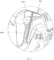
FIG. 2 is an enlarged view of section A inFIG. 1 ; -
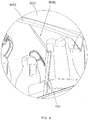
FIG. 3 is an enlarged view of portion B inFIG. 1 ; -
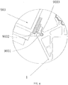
FIG. 4 is an enlarged view of portion C inFIG. 1 ; -
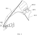
FIG. 5 is a partial cross-sectional view of the connection between the front compartment door and the vehicle body in the electric vehicle according to an embodiment of the present invention; -
FIG. 6 is an enlarged view of portion D inFIG. 5 ; -
FIG. 7 is a partial cross-sectional view of the connection between the front cover and the front door in the electric vehicle according to an embodiment of the present invention; -
FIG.8 shows a first state of the electric vehicle according to an embodiment of the present invention; -
FIG.9 shows a second state of the electric vehicle according to an embodiment of the present invention; -
FIG.10 shows a third state of the electric vehicle according to an embodiment of the present invention; - To make the objectives, technical solutions, and advantages of the present invention clearer and more comprehensible, the following further describes the present invention in detail referring to the accompanying drawings and embodiments. It should be understood that the specific embodiment described herein is merely used to explain the present invention but is not used to limit the present invention.
- The implementation of the present invention is described in detail with reference to specific embodiments in the following.
- As shown in
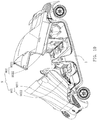
FIG 1 to FIG. 10 , the present invention provides a preferred embodiment. - This embodiment provides a front-and-
rear split door 9, used in an electric vehicle, comprising avehicle body 1 and apassenger compartment 101 disposed on thevehicle body 1, wherein the front-and-rear split door comprises afront compartment door 901 and arear compartment door 902 configured to open or close apassenger compartment 101, wherein thefront compartment door 901 and therear compartment door 902 are provided above thepassenger compartment 101; a front end of thefront compartment door 901 is connected to avehicle body 1 via afirst hinge assembly 903, a rear end of therear compartment door 902 is connected to thevehicle body 1 via asecond hinge assembly 904; and the electric vehicle further comprises afirst turning mechanism 905 configured to control thefront compartment door 901 to turn outwardly about thefirst hinge assembly 903 and asecond turning mechanism 906 configured to control therear compartment door 902 to turn outwardly about thesecond hinge assembly 904. - In the front-and-
rear split door 9, thefront compartment door 901 is driven by thefirst turning mechanism 905 to turn about thefirst hinge assembly 903 to open and close the front opening of thepassenger compartment 101, and therear compartment door 902 is driven by thesecond turning mechanism 906 to turn about thesecond hinge assembly 904 to open and close the opening of thepassenger compartment 101, so that there is no need to design an A pillar and a C pillar on thevehicle body 1, such that the driver can have a broader view, thereby improving the driving comfort, and the weight of thevehicle body 1 will also be reduced, so that the vehicle performance is improved. - In this embodiment, referring to
FIG. 1 ,FIG. 4 to FIG. 6 , thefirst hinge assembly 903 comprises afirst hinge base 9031 disposed on thevehicle body 1 and afirst hinge member 9032 with one end disposed in thefirst hinge base 9031 and rotatable oppositely with respect to thefirst hinge base 9031. Thefirst hinge base 9031 comprises afixing groove 9033 horizontally disposed on thevehicle body 1, thefixing groove 9033 is parallel to the width direction of the vehicle. Thefirst hinge member 9032 is a plate which is bended, one end of the bended plate hinged with thefirst hinge base 9031 is provided with a circular cross-section matched with thefixing groove 9033, the other end of thefirst hinge member 9032 extends out of the opening of thefixing grooves 9033 and is fixed to thefront compartment door 901, the turning of thefirst hinge member 9032 is limited by an opening angle of the opening of thefixing grooves 9033. Thesecond hinge assembly 904 comprises a second hinge base disposed on the rear end of thevehicle body 1 and a second hinge member with one end disposed in the second hinge base and rotatable oppositely with respect to the second hinge base. The second hinge base and the second hinge member have the same shapes and arrangements as the first hinge base and the first hinge member. Another end of the second hinge member is fixed to therear compartment door 902. - Referring to
Figures 1 and2 , thefirst turning mechanism 905 comprises a pair of first pneumatic struts disposed on two sides of the front portion of thepassenger compartment 101 and a first pump configured to fill high-pressure gas to the firstpneumatic strut 9051 to allow the firstpneumatic strut 9051 to drive thefront compartment door 901 to turn, two ends of each firstpneumatic strut 9051 are respectively connected to thefront compartment door 901 and thevehicle body 1 via universal joints. Thesecond turning mechanism 906 comprises a pair of secondpneumatic struts 9061 disposed on two sides of the rear portion of thepassenger compartment 101 and a second pump configured to fill high-pressure gas to the secondpneumatic strut 9061 to allow the secondpneumatic strut 9061 to drive therear compartment door 902 to turn, two ends of each secondpneumatic strut 9061 are respectively connected to therear compartment door 902 and thevehicle body 1 via universal joints. - To allow the passengers in and out of the vehicle easier, it can be seen from
FIG. 1 , thefront compartment door 901 comprises afront cover 9011 and twofront doors 9012 respectively connected to two sides of thefront cover 9011; therear compartment door 902 comprises arear cover 9021 and tworear doors 9022 respectively connected to two sides of therear cover 9021. Thefront cover 9011 and therear cover 9021 are arc shaped, a front side of thefront cover body 9011 is served as a windshield, thefront cover 9011 and therear cover 9021 are made of glass or transparent material, and coated with insulation film. The electric vehicle further comprises a firstlinkage turning device 907 configured to turn each of thefront doors 9012 in a linkage manner when turned withfront compartment door 901 and a secondlinkage turning device 908 configured to turn each of therear doors 9022 in a linkage manner when turned withrear compartment door 902. Thus, when thefront compartment door 901 and therear compartment door 902 are opened, the front door 9012and therear compartment door 9022 are turned outwardly simultaneously at the same time and form a flat extending state like a crane, which enlarges the space for getting on and off on both sides of the electric vehicle, to facilitate getting in and out of the car for the passengers. - Of course, the
front compartment door 901 and therear compartment door 902 may be formed integrally, it just have to make sure that thefront compartment door 901 andrear compartment door 902 has a larger angle when they are opened. - In this embodiment, the first
linkage turning device 907 comprises athird hinge assembly 9071 connected between the respectivefront door 9012 and thefront cover 9011 and athird turning mechanism 9072 connected between the respectivefront door 9012 and thevehicle body 1 and configured to drive the respectivefront door 9012 to turn about thethird hinge assembly 9071 when thefront compartment door 901 is turned; the secondlinkage turning device 908 comprises afourth hinge assembly 9081 connected between the respectiverear door 9022 and therear cover 9021 and afourth turning mechanism 9082 connected between the respectiverear door 9022 and thevehicle body 1 and is configured to drive the respectiverear door 9022 to turn about thethird hinge assembly 9081 when therear compartment door 902 is turned. - Referring to
FIGS. 1 and7 , thethird hinge assembly 9071 comprisesfirst fixing shafts 90711 disposed on two sides of thefront cover 9011 andthird hinge members 90712 each with one end sleeving thefirst fixing shaft 90711 and rotatable oppositely with respect to thefirst fixing shaft 90711, the other end of thethird hinge member 90712 is fixed to thefront door 9012, thethird hinge assembly 9071 comprises a flat surface portion hinged with thefirst fixing shaft 90711 and an arc surface portion connected with thefront door 9012; thefourth hinge assembly 9081 comprises second fixing shafts 90811 disposed on two sides of therear cover 9021 and each with one end sleeving the second fixing shaft 90811 and rotatable oppositely with respect to the second fixing shaft 90811, the other end of the fourth hinge member 90812 is fixed to therear door 9022. The connection manner and shape of the second fixing shafts 90811 and the fourth hinge members 90812 are the same as thefirst fixing shafts 90711 and thethird hinge members 90712 respectively. - The
third reversing mechanism 9072 comprises a pair offirst air springs 90721, fromFIGS 1 ,2 and4 , it can be seen that each of thefirst air spring 90721 comprises afirst end 90721a connected to thevehicle body 1 via the universal joint and asecond end 90721b connected to thefront door 9012. When thefront compartment door 901 is closed, thefirst end 90721a is above thesecond end 90721b, the first air springs are rotated 90721 with thefront compartment door 901 when thefront compartment door 901 is opening, the rotation surface of the first air springs and the rotation surface of the firstpneumatic strut 9051 has a certain angle. When thefront compartment door 901 is opened, thefirst end 90721 a is below thesecond end 90721b. Thefourth turning mechanism 9082 comprises a pair of second air spring 90821, thevehicle body 1 is provided with twolongitudinal fixing columns 102 on two sides, each of the second air springs 90821 is respectively connected to the respectiverear door 9022 and a top end of therespective fixing column 102 via universal joints. Thefourth turning mechanism 9082 has the same structure as theturning mechanism 9072. - The
front compartment door 901 and therear compartment door 902 may be respectively turned forth and back synchronously or asynchronously, that is, they are turned like a bloom. Thefront door 9012 and therear door 9022 also may be respectively turned broadwise synchronously or asynchronously, that is, they are turned like the procedure that the crane expands its wings. In order to limit the magnitude of turning, and to avoid the damage caused by the turning of large angle, the firstpneumatic strut 9051, the secondpneumatic strut 9061, thefirst air spring 90721, and the second air spring 90821 may be respectively provided with a travel-limiting block. - In order to achieve air circulation between inside and outside of the vehicle, the
front compartment door 901 and/or therear compartment door 902 is provided with an air window 909. The air window 909 may be adjusted manually or electrically to meet the requirements of the vehicle ventilation required by the passengers when the air conditioning isn't used. - In order to manually open and close the
front compartment door 901 and therear compartment door 902 of thepassenger compartment 101, thefront compartment door 901 and therear compartment door 902 is provide with a handle. - The
front compartment door 901 and/or therear compartment door 902 is made of glass or transparent PC. In order to make use of the sunlight, at least a part offront compartment door 901 and/or therear compartment door 902 is made of crystalline silicon capable of absorbing sunlight, to use solar energy to supplement the energy of the power supply system of the vehicle. - To avoid premature aging caused by the sun,
front compartment door 901 and/or therear compartment door 902 is covered with a reflective PVC film. - The opening procedure and principle of the
front compartment door 901 of the electric vehicle of the present invention are described in the follow with reference toFIGS. 1 ,8 to 10 . - The present invention also provides electric vehicle comprising a vehicle body and a front-and-rear split door mentioned above, from front to rear, the vehicle body is provided with a front luggage compartment, a
passenger compartment 101 and a rear luggage compartment, the front-and-rear split door comprises thefront compartment door 901 connected to the front end of thepassenger compartment 101 and therear compartment door 902 connected to the rear end of thepassenger compartment 101. - In the electric vehicle mentioned above, the
front compartment door 901 may be turned outwardly to open and close the front opening of thepassenger compartment 101, and therear compartment door 902 may be turned outwardly and oppositely with respect tofront compartment door 901 to open and close the opening of thepassenger compartment 101, so that there is no need to design an A pillar and a C pillar on thevehicle body 1, such that the driver can have a broader view, thereby improving the driving comfort, and the weight of thevehicle body 1 will also be reduced, so that the vehicle performance is improved. - When the
front compartment door 901 is closed, thefirst end 90721a of thefirst air spring 90721 is above thesecond end 90721b of thefirst air spring 90721, thefirst air spring 90721 is in force equilibrium state. When thefront compartment door 901 is turned outwardly about thefirst hinge assembly 903 through the firstpneumatic struts 9051, thefirst air spring 90721 is pulled by thefront door 9012 and rotate with thefront door 9012, meanwhile thefirst air spring 90721 is out of the force equilibrium state, thefirst air spring 90721 extends out of the push shaft due to the internal pressure thereof, there is an angle between the plane where thefirst air spring 90721 rotates and the plane where the firstpneumatic strut 9051 rotates; when thefront compartment door 901 is opened to the highest level, thefront door 9012 extend to a position where thefirst air spring 90721 has a maximum stroke, at this time thefirst end 90721a is below thesecond end 90721b. - The opening process and principle of the
rear compartment door 902 is the same as that offront compartment door 901, and will not be described repeatedly below. - The foregoing descriptions are merely exemplary embodiment of the present invention, but are not intended to limit the present invention. Any modification, equivalent replacement, or improvement made without departing from the spirit and principle of the present invention shall fall within the protection scope of the present invention.
Claims (13)
- A front-and-rear split door, used in an electric vehicle, comprising a vehicle body and a passenger compartment disposed on the vehicle body, wherein the front-and-rear split door comprises a front compartment door and a rear compartment door configured to open or close a passenger compartment, characterized in that the front compartment door and the rear compartment door are provided above the passenger compartment; a front end of the front compartment door is connected to a vehicle body via a first hinge assembly, a rear end of the rear compartment door is connected to the vehicle body via a second hinge assembly; and the electric vehicle further comprises a first turning mechanism configured to control the front compartment door to turn outwardly about the first hinge assembly and a second turning mechanism configured to control the rear compartment door to turn outwardly about the second hinge assembly.
- The front-and-rear split door of claim 1, characterized in that the front compartment door comprises a front cover and two front doors respectively connected to two sides of the front cover, the rear compartment door comprises a rear cover and two rear doors respectively connected to two sides of the rear cover; the electric vehicle further comprises a first linkage turning device configured to turn each of the front doors in a linkage manner when turned with front compartment door and a second linkage turning device configured to turn each of the rear doors in a linkage manner when turned with rear compartment door.
- The front-and-rear split door of claim 2, characterized in that the first linkage turning device comprises a third hinge assembly connected between the respective front door and the front cover and a third turning mechanism connected between the respective front door and the vehicle body and is configured to drive the respective front door to turn about the third hinge assembly when the front compartment door is turned; the second linkage turning device comprises a fourth hinge assembly connected between the respective rear door and the rear cover and a fourth turning mechanism connected between the respective rear door and the vehicle body and configured to drive the respective rear door to turn about the third hinge assembly when the rear compartment door is turned.
- The front-and-rear split door of claim 1, characterized in that: the first hinge assembly comprises a first hinge base disposed on the vehicle body and a first hinge member with one end disposed in the first hinge base and rotatable oppositely with respect to the first hinge base, another end of the first hinge member is fixed to the front compartment door; and the second hinge assembly comprises a second hinge base disposed on the vehicle body and a second hinge member with one end disposed in the second hinge base and rotatable oppositely with respect to the second hinge base, another end of the second hinge member is fixed to the rear compartment door.
- The front-and-rear split door of claim 1 or 4, characterized in that the first turning mechanism comprises at least one first pneumatic strut with two ends respectively connected to the front compartment door and the vehicle body via universal joints and a first pump configured to fill high-pressure gas to the first pneumatic strut to allow the first pneumatic strut to drive the front compartment door to turn; the second turning mechanism comprises at least one second pneumatic strut with two ends respectively connected to the rear compartment door and the vehicle body via universal joints and a second pump configured to fill high-pressure gas to the second pneumatic strut to allow the second pneumatic strut to drive the rear compartment door to turn.
- The front-and-rear split door of claim 3, characterized in that the third hinge assembly comprises first fixing shafts disposed on two sides of the front cover and third hinge members each with one end sleeving the first fixing shaft and rotatable oppositely with respect to the first fixing shaft, the other end of the third hinge member is fixed to the front door; the fourth hinge assembly comprises second fixing shafts disposed on two sides of the rear cover and fourth hinge members each with one end sleeving the second fixing shaft and rotatable oppositely with respect to the second fixing shaft, the other end of the fourth hinge member is fixed to the rear door.
- The front-and-rear split door of claim 3 or 6, characterized in that the third turning mechanism comprises at least one pair of first air springs, two ends of each air spring are respectively connected to the respective front door and the vehicle body via universal joints; the fourth turning mechanism comprises at least one pair of second air springs, the vehicle body is provided with two longitudinal fixing columns on two sides, each of the second air springs is respectively connected to the respective rear door and a top end of the respective fixing column via universal joints.
- The front-and-rear split door of any of claims 1-7, characterized in that the front compartment door and/or the rear compartment door is provided with an air window.
- The front-and-rear split door of any of claims 1-8, characterized in that the front compartment door and/or the rear compartment door is provided with a handle.
- The front-and-rear split door of any of claims 1-9, characterized in that the front compartment door and/or the rear compartment door is made of glass or transparent PC.
- The front-and-rear split door of any of claims 1-10, characterized in that at least a part of the front compartment door and/or the rear compartment door is made of crystalline silicon capable of absorbing sunlight.
- The front-and-rear split door of any of claims 1-10, characterized in that at least a part of the front compartment door and/or the rear compartment door is covered with a reflective PVC film.
- An electric vehicle comprising a vehicle body and a front-and-rear split door of any of claims 1-12, from front to rear, the vehicle body is provided with a front luggage compartment, a passenger compartment and a rear luggage compartment, the front-and-rear split door comprises the front compartment door connected to the front end of the passenger compartment and the rear compartment door connected to the rear end of the passenger compartment.
Priority Applications (1)
| Application Number | Priority Date | Filing Date | Title |
|---|---|---|---|
| PL14887744T PL3127730T3 (en) | 2014-04-01 | 2014-04-01 | Vehicle door with front and rear parts opening in opposite directions and electric vehicle having same |
Applications Claiming Priority (1)
| Application Number | Priority Date | Filing Date | Title |
|---|---|---|---|
| PCT/CN2014/074552 WO2015149284A1 (en) | 2014-04-01 | 2014-04-01 | Vehicle door with front and rear parts opening in opposite directions and electric vehicle having same |
Publications (3)
| Publication Number | Publication Date |
|---|---|
| EP3127730A1 true EP3127730A1 (en) | 2017-02-08 |
| EP3127730A4 EP3127730A4 (en) | 2017-12-27 |
| EP3127730B1 EP3127730B1 (en) | 2019-06-05 |
Family
ID=54239269
Family Applications (1)
| Application Number | Title | Priority Date | Filing Date |
|---|---|---|---|
| EP14887744.2A Active EP3127730B1 (en) | 2014-04-01 | 2014-04-01 | Vehicle door with front and rear parts opening in opposite directions and electric vehicle having same |
Country Status (8)
| Country | Link |
|---|---|
| US (1) | US10137765B2 (en) |
| EP (1) | EP3127730B1 (en) |
| JP (1) | JP6383006B2 (en) |
| KR (1) | KR20160138109A (en) |
| CN (1) | CN106068195B (en) |
| ES (1) | ES2743736T3 (en) |
| PL (1) | PL3127730T3 (en) |
| WO (1) | WO2015149284A1 (en) |
Cited By (1)
| Publication number | Priority date | Publication date | Assignee | Title |
|---|---|---|---|---|
| EP3699004A1 (en) * | 2019-02-20 | 2020-08-26 | Toyota Jidosha Kabushiki Kaisha | Vehicle |
Families Citing this family (4)
| Publication number | Priority date | Publication date | Assignee | Title |
|---|---|---|---|---|
| US11358445B1 (en) * | 2018-10-05 | 2022-06-14 | Glydways, Inc. | Vehicle with twin canopy doors |
| CN110329045A (en) * | 2019-06-21 | 2019-10-15 | 芜湖莫森泰克汽车科技股份有限公司 | A kind of electric drive method and structure for realizing opening side door of vehicle |
| KR102817479B1 (en) * | 2019-12-10 | 2025-06-05 | 현대자동차주식회사 | Structure for Bidirectional Door of Vehicle |
| CN112744058B (en) * | 2021-01-07 | 2022-08-05 | 广西汽车集团有限公司 | Gate for preventing passengers from freely getting on or off bus |
Family Cites Families (25)
| Publication number | Priority date | Publication date | Assignee | Title |
|---|---|---|---|---|
| GB598633A (en) * | 1945-04-07 | 1948-02-23 | Marcel Antoine Clement Alamagn | Improvements in or relating to bodies for automobile vehicles |
| US2656214A (en) * | 1945-04-07 | 1953-10-20 | Alamagny Marcel Antoin Clement | Automobile body having pivoted end sections |
| FR996011A (en) * | 1945-04-09 | 1951-12-12 | Motor vehicle | |
| US2777728A (en) * | 1949-09-23 | 1957-01-15 | Daimler Benz Ag | Motor vehicle accessible by means of a pivotal cap |
| CH289566A (en) * | 1949-09-23 | 1953-03-15 | Barenyi Bela | Motor vehicle. |
| US2947567A (en) * | 1956-06-18 | 1960-08-02 | Daimler Benz Ag | Automobile top structure |
| GB789284A (en) * | 1956-06-25 | 1958-01-15 | Daimler Benz Ag | Improvements relating to passenger motor vehicles with roof parts adapted to be hingedly opened |
| US3425740A (en) * | 1966-08-15 | 1969-02-04 | Marshall S De Vaughn | Streamlining apparatus |
| US3856106A (en) * | 1969-06-23 | 1974-12-24 | Otis Elevator Co | Vehicle body construction |
| US3979147A (en) * | 1975-03-14 | 1976-09-07 | Kelley Robert F | Transparent cover with connecting devices for motorcycles and riders |
| JPS59202931A (en) * | 1983-04-28 | 1984-11-16 | Honda Motor Co Ltd | car door device |
| JPH0454014Y2 (en) * | 1987-09-30 | 1992-12-18 | ||
| JPH0516670A (en) * | 1991-07-15 | 1993-01-26 | Mazda Motor Corp | Vehicle with wing door |
| US5806620A (en) * | 1995-10-27 | 1998-09-15 | Chrysler Corporation | Unitary one-piece automobile hood, fascia, and front fender assembly |
| US5806622A (en) * | 1996-04-24 | 1998-09-15 | Nev Corporation | Lightweight vehicle with pivotal canopy |
| DE29703663U1 (en) * | 1997-02-28 | 1998-08-20 | Sommer Ulrich | Passenger cars with a supporting structure that has at least two side members |
| IT1297118B1 (en) * | 1997-12-15 | 1999-08-03 | Vigano Giorgio | TILTING ACCESS TO THE CABIN OF TRANSPORT VEHICLES |
| JP2002348151A (en) * | 2001-05-25 | 2002-12-04 | Nippon Sheet Glass Co Ltd | Heat ray reflecting laminated windsheld glass |
| JP4279063B2 (en) * | 2003-06-27 | 2009-06-17 | 三菱化学株式会社 | Porous silica film and laminate having the same |
| EP1745957B1 (en) * | 2005-07-18 | 2008-10-29 | GM Global Technology Operations, Inc. | Vehicle door opening system |
| JP2007308113A (en) * | 2006-05-22 | 2007-11-29 | Toyota Motor Corp | Vehicle door structure |
| DE102008043174A1 (en) | 2008-10-24 | 2010-04-29 | Ford Global Technologies, LLC, Dearborn | Motor vehicle, particularly passenger car, comprises scissor style door whose rotational axis is provided outside of door frame in front vehicle area, where scissor style door is pivoted in mudguard contour or in curved track |
| DE202009007273U1 (en) * | 2009-05-20 | 2010-10-07 | Luggenhölscher, Alfred, Dipl.-Ing. | Passenger cars |
| JP2011068317A (en) * | 2009-09-28 | 2011-04-07 | Honda Motor Co Ltd | Door structure of vehicle |
| DE102011112571A1 (en) * | 2011-09-08 | 2013-03-14 | GM Global Technology Operations LLC (n. d. Gesetzen des Staates Delaware) | Opening and / or closing device |
-
2014
- 2014-04-01 KR KR1020167028263A patent/KR20160138109A/en not_active Ceased
- 2014-04-01 JP JP2016560758A patent/JP6383006B2/en not_active Expired - Fee Related
- 2014-04-01 CN CN201480076945.XA patent/CN106068195B/en active Active
- 2014-04-01 WO PCT/CN2014/074552 patent/WO2015149284A1/en not_active Ceased
- 2014-04-01 EP EP14887744.2A patent/EP3127730B1/en active Active
- 2014-04-01 ES ES14887744T patent/ES2743736T3/en active Active
- 2014-04-01 PL PL14887744T patent/PL3127730T3/en unknown
- 2014-04-01 US US15/300,702 patent/US10137765B2/en active Active
Cited By (1)
| Publication number | Priority date | Publication date | Assignee | Title |
|---|---|---|---|---|
| EP3699004A1 (en) * | 2019-02-20 | 2020-08-26 | Toyota Jidosha Kabushiki Kaisha | Vehicle |
Also Published As
| Publication number | Publication date |
|---|---|
| US10137765B2 (en) | 2018-11-27 |
| JP6383006B2 (en) | 2018-08-29 |
| JP2017509545A (en) | 2017-04-06 |
| KR20160138109A (en) | 2016-12-02 |
| PL3127730T3 (en) | 2020-01-31 |
| EP3127730A4 (en) | 2017-12-27 |
| US20170106730A1 (en) | 2017-04-20 |
| ES2743736T3 (en) | 2020-02-20 |
| EP3127730B1 (en) | 2019-06-05 |
| CN106068195B (en) | 2018-02-27 |
| CN106068195A (en) | 2016-11-02 |
| WO2015149284A1 (en) | 2015-10-08 |
Similar Documents
| Publication | Publication Date | Title |
|---|---|---|
| EP3127730B1 (en) | Vehicle door with front and rear parts opening in opposite directions and electric vehicle having same | |
| US7399022B2 (en) | Vehicle rear door | |
| US9266413B2 (en) | Opening and/or closing device | |
| KR100862498B1 (en) | Car air vent structure | |
| CN103373320B (en) | Automobile-used Wiping device | |
| US20170122022A1 (en) | Structure for unifying motor for use with rear curtain and power trunk | |
| KR102201861B1 (en) | Door garnish assembly and manufacturing method thereof | |
| US7086682B2 (en) | Device for obturation of an aperture for an automotive vehicle | |
| KR100784673B1 (en) | Vehicles equipped with sun visor and air assist brake. | |
| CN109318860B (en) | Cab and engineering vehicle | |
| JPS6288611A (en) | Flapping type frameless rear window for car | |
| CN206264759U (en) | Multi-platform generalization electric exterior swing door structure | |
| CN206885182U (en) | Body of a motor car and automobile | |
| CN111267961A (en) | Cage type full-view cabin of automobile | |
| US20250222750A1 (en) | Vehicle visor systems with multidrectional shading | |
| CN210733993U (en) | Luggage rack and vehicle | |
| EP3854653B1 (en) | Window system with glass panel with variable opacity | |
| WO2021068409A1 (en) | Liftable roof device for vehicle, and vehicle | |
| CN222260853U (en) | Car window lifting button | |
| WO2026086447A1 (en) | Sunroof shading device and vehicle | |
| KR200372828Y1 (en) | sunvisor of car | |
| CN205149462U (en) | Car cabin cover and car | |
| CN220662671U (en) | A tail wing lifting device and vehicle | |
| CN203063819U (en) | Novel rearview mirror for large bus | |
| CN203093893U (en) | Automobile rearview mirror mechanism |
Legal Events
| Date | Code | Title | Description |
|---|---|---|---|
| STAA | Information on the status of an ep patent application or granted ep patent |
Free format text: STATUS: THE INTERNATIONAL PUBLICATION HAS BEEN MADE |
|
| PUAI | Public reference made under article 153(3) epc to a published international application that has entered the european phase |
Free format text: ORIGINAL CODE: 0009012 |
|
| STAA | Information on the status of an ep patent application or granted ep patent |
Free format text: STATUS: REQUEST FOR EXAMINATION WAS MADE |
|
| 17P | Request for examination filed |
Effective date: 20161025 |
|
| AK | Designated contracting states |
Kind code of ref document: A1 Designated state(s): AL AT BE BG CH CY CZ DE DK EE ES FI FR GB GR HR HU IE IS IT LI LT LU LV MC MK MT NL NO PL PT RO RS SE SI SK SM TR |
|
| AX | Request for extension of the european patent |
Extension state: BA ME |
|
| DAX | Request for extension of the european patent (deleted) | ||
| A4 | Supplementary search report drawn up and despatched |
Effective date: 20171128 |
|
| RIC1 | Information provided on ipc code assigned before grant |
Ipc: B60J 5/04 20060101AFI20171122BHEP Ipc: B60J 7/08 20060101ALI20171122BHEP |
|
| GRAP | Despatch of communication of intention to grant a patent |
Free format text: ORIGINAL CODE: EPIDOSNIGR1 |
|
| STAA | Information on the status of an ep patent application or granted ep patent |
Free format text: STATUS: GRANT OF PATENT IS INTENDED |
|
| INTG | Intention to grant announced |
Effective date: 20181116 |
|
| GRAS | Grant fee paid |
Free format text: ORIGINAL CODE: EPIDOSNIGR3 |
|
| RAP1 | Party data changed (applicant data changed or rights of an application transferred) |
Owner name: GUANGDONG HUA'CHAN RESEARCH INSTITUTE OF INTELLIGE |
|
| GRAA | (expected) grant |
Free format text: ORIGINAL CODE: 0009210 |
|
| STAA | Information on the status of an ep patent application or granted ep patent |
Free format text: STATUS: THE PATENT HAS BEEN GRANTED |
|
| AK | Designated contracting states |
Kind code of ref document: B1 Designated state(s): AL AT BE BG CH CY CZ DE DK EE ES FI FR GB GR HR HU IE IS IT LI LT LU LV MC MK MT NL NO PL PT RO RS SE SI SK SM TR |
|
| REG | Reference to a national code |
Ref country code: GB Ref legal event code: FG4D |
|
| REG | Reference to a national code |
Ref country code: CH Ref legal event code: EP |
|
| REG | Reference to a national code |
Ref country code: AT Ref legal event code: REF Ref document number: 1139628 Country of ref document: AT Kind code of ref document: T Effective date: 20190615 |
|
| REG | Reference to a national code |
Ref country code: IE Ref legal event code: FG4D |
|
| REG | Reference to a national code |
Ref country code: DE Ref legal event code: R096 Ref document number: 602014048021 Country of ref document: DE |
|
| REG | Reference to a national code |
Ref country code: CH Ref legal event code: NV Representative=s name: DENNEMEYER AG, CH |
|
| REG | Reference to a national code |
Ref country code: NL Ref legal event code: FP |
|
| REG | Reference to a national code |
Ref country code: LT Ref legal event code: MG4D |
|
| PG25 | Lapsed in a contracting state [announced via postgrant information from national office to epo] |
Ref country code: AL Free format text: LAPSE BECAUSE OF FAILURE TO SUBMIT A TRANSLATION OF THE DESCRIPTION OR TO PAY THE FEE WITHIN THE PRESCRIBED TIME-LIMIT Effective date: 20190605 Ref country code: SE Free format text: LAPSE BECAUSE OF FAILURE TO SUBMIT A TRANSLATION OF THE DESCRIPTION OR TO PAY THE FEE WITHIN THE PRESCRIBED TIME-LIMIT Effective date: 20190605 Ref country code: HR Free format text: LAPSE BECAUSE OF FAILURE TO SUBMIT A TRANSLATION OF THE DESCRIPTION OR TO PAY THE FEE WITHIN THE PRESCRIBED TIME-LIMIT Effective date: 20190605 Ref country code: NO Free format text: LAPSE BECAUSE OF FAILURE TO SUBMIT A TRANSLATION OF THE DESCRIPTION OR TO PAY THE FEE WITHIN THE PRESCRIBED TIME-LIMIT Effective date: 20190905 Ref country code: LT Free format text: LAPSE BECAUSE OF FAILURE TO SUBMIT A TRANSLATION OF THE DESCRIPTION OR TO PAY THE FEE WITHIN THE PRESCRIBED TIME-LIMIT Effective date: 20190605 Ref country code: FI Free format text: LAPSE BECAUSE OF FAILURE TO SUBMIT A TRANSLATION OF THE DESCRIPTION OR TO PAY THE FEE WITHIN THE PRESCRIBED TIME-LIMIT Effective date: 20190605 |
|
| PG25 | Lapsed in a contracting state [announced via postgrant information from national office to epo] |
Ref country code: RS Free format text: LAPSE BECAUSE OF FAILURE TO SUBMIT A TRANSLATION OF THE DESCRIPTION OR TO PAY THE FEE WITHIN THE PRESCRIBED TIME-LIMIT Effective date: 20190605 Ref country code: LV Free format text: LAPSE BECAUSE OF FAILURE TO SUBMIT A TRANSLATION OF THE DESCRIPTION OR TO PAY THE FEE WITHIN THE PRESCRIBED TIME-LIMIT Effective date: 20190605 Ref country code: GR Free format text: LAPSE BECAUSE OF FAILURE TO SUBMIT A TRANSLATION OF THE DESCRIPTION OR TO PAY THE FEE WITHIN THE PRESCRIBED TIME-LIMIT Effective date: 20190906 Ref country code: BG Free format text: LAPSE BECAUSE OF FAILURE TO SUBMIT A TRANSLATION OF THE DESCRIPTION OR TO PAY THE FEE WITHIN THE PRESCRIBED TIME-LIMIT Effective date: 20190905 |
|
| PG25 | Lapsed in a contracting state [announced via postgrant information from national office to epo] |
Ref country code: PT Free format text: LAPSE BECAUSE OF FAILURE TO SUBMIT A TRANSLATION OF THE DESCRIPTION OR TO PAY THE FEE WITHIN THE PRESCRIBED TIME-LIMIT Effective date: 20191007 Ref country code: SK Free format text: LAPSE BECAUSE OF FAILURE TO SUBMIT A TRANSLATION OF THE DESCRIPTION OR TO PAY THE FEE WITHIN THE PRESCRIBED TIME-LIMIT Effective date: 20190605 Ref country code: CZ Free format text: LAPSE BECAUSE OF FAILURE TO SUBMIT A TRANSLATION OF THE DESCRIPTION OR TO PAY THE FEE WITHIN THE PRESCRIBED TIME-LIMIT Effective date: 20190605 Ref country code: EE Free format text: LAPSE BECAUSE OF FAILURE TO SUBMIT A TRANSLATION OF THE DESCRIPTION OR TO PAY THE FEE WITHIN THE PRESCRIBED TIME-LIMIT Effective date: 20190605 Ref country code: RO Free format text: LAPSE BECAUSE OF FAILURE TO SUBMIT A TRANSLATION OF THE DESCRIPTION OR TO PAY THE FEE WITHIN THE PRESCRIBED TIME-LIMIT Effective date: 20190605 |
|
| PG25 | Lapsed in a contracting state [announced via postgrant information from national office to epo] |
Ref country code: IS Free format text: LAPSE BECAUSE OF FAILURE TO SUBMIT A TRANSLATION OF THE DESCRIPTION OR TO PAY THE FEE WITHIN THE PRESCRIBED TIME-LIMIT Effective date: 20191005 Ref country code: IT Free format text: LAPSE BECAUSE OF FAILURE TO SUBMIT A TRANSLATION OF THE DESCRIPTION OR TO PAY THE FEE WITHIN THE PRESCRIBED TIME-LIMIT Effective date: 20190605 Ref country code: SM Free format text: LAPSE BECAUSE OF FAILURE TO SUBMIT A TRANSLATION OF THE DESCRIPTION OR TO PAY THE FEE WITHIN THE PRESCRIBED TIME-LIMIT Effective date: 20190605 |
|
| REG | Reference to a national code |
Ref country code: DE Ref legal event code: R097 Ref document number: 602014048021 Country of ref document: DE |
|
| PLBE | No opposition filed within time limit |
Free format text: ORIGINAL CODE: 0009261 |
|
| STAA | Information on the status of an ep patent application or granted ep patent |
Free format text: STATUS: NO OPPOSITION FILED WITHIN TIME LIMIT |
|
| PG25 | Lapsed in a contracting state [announced via postgrant information from national office to epo] |
Ref country code: DK Free format text: LAPSE BECAUSE OF FAILURE TO SUBMIT A TRANSLATION OF THE DESCRIPTION OR TO PAY THE FEE WITHIN THE PRESCRIBED TIME-LIMIT Effective date: 20190605 |
|
| 26N | No opposition filed |
Effective date: 20200306 |
|
| PG25 | Lapsed in a contracting state [announced via postgrant information from national office to epo] |
Ref country code: SI Free format text: LAPSE BECAUSE OF FAILURE TO SUBMIT A TRANSLATION OF THE DESCRIPTION OR TO PAY THE FEE WITHIN THE PRESCRIBED TIME-LIMIT Effective date: 20190605 |
|
| PG25 | Lapsed in a contracting state [announced via postgrant information from national office to epo] |
Ref country code: MC Free format text: LAPSE BECAUSE OF FAILURE TO SUBMIT A TRANSLATION OF THE DESCRIPTION OR TO PAY THE FEE WITHIN THE PRESCRIBED TIME-LIMIT Effective date: 20190605 |
|
| PG25 | Lapsed in a contracting state [announced via postgrant information from national office to epo] |
Ref country code: LU Free format text: LAPSE BECAUSE OF NON-PAYMENT OF DUE FEES Effective date: 20200401 |
|
| PG25 | Lapsed in a contracting state [announced via postgrant information from national office to epo] |
Ref country code: IE Free format text: LAPSE BECAUSE OF NON-PAYMENT OF DUE FEES Effective date: 20200401 |
|
| PGFP | Annual fee paid to national office [announced via postgrant information from national office to epo] |
Ref country code: TR Payment date: 20210330 Year of fee payment: 8 |
|
| PGFP | Annual fee paid to national office [announced via postgrant information from national office to epo] |
Ref country code: PL Payment date: 20210331 Year of fee payment: 8 Ref country code: ES Payment date: 20210621 Year of fee payment: 8 Ref country code: BE Payment date: 20210420 Year of fee payment: 8 Ref country code: AT Payment date: 20210421 Year of fee payment: 8 |
|
| PGFP | Annual fee paid to national office [announced via postgrant information from national office to epo] |
Ref country code: NL Payment date: 20210420 Year of fee payment: 8 |
|
| REG | Reference to a national code |
Ref country code: AT Ref legal event code: UEP Ref document number: 1139628 Country of ref document: AT Kind code of ref document: T Effective date: 20190605 |
|
| PG25 | Lapsed in a contracting state [announced via postgrant information from national office to epo] |
Ref country code: MT Free format text: LAPSE BECAUSE OF FAILURE TO SUBMIT A TRANSLATION OF THE DESCRIPTION OR TO PAY THE FEE WITHIN THE PRESCRIBED TIME-LIMIT Effective date: 20190605 Ref country code: CY Free format text: LAPSE BECAUSE OF FAILURE TO SUBMIT A TRANSLATION OF THE DESCRIPTION OR TO PAY THE FEE WITHIN THE PRESCRIBED TIME-LIMIT Effective date: 20190605 |
|
| PG25 | Lapsed in a contracting state [announced via postgrant information from national office to epo] |
Ref country code: MK Free format text: LAPSE BECAUSE OF FAILURE TO SUBMIT A TRANSLATION OF THE DESCRIPTION OR TO PAY THE FEE WITHIN THE PRESCRIBED TIME-LIMIT Effective date: 20190605 |
|
| REG | Reference to a national code |
Ref country code: NL Ref legal event code: MM Effective date: 20220501 |
|
| REG | Reference to a national code |
Ref country code: AT Ref legal event code: MM01 Ref document number: 1139628 Country of ref document: AT Kind code of ref document: T Effective date: 20220401 |
|
| REG | Reference to a national code |
Ref country code: BE Ref legal event code: MM Effective date: 20220430 |
|
| PG25 | Lapsed in a contracting state [announced via postgrant information from national office to epo] |
Ref country code: NL Free format text: LAPSE BECAUSE OF NON-PAYMENT OF DUE FEES Effective date: 20220501 Ref country code: AT Free format text: LAPSE BECAUSE OF NON-PAYMENT OF DUE FEES Effective date: 20220401 |
|
| PG25 | Lapsed in a contracting state [announced via postgrant information from national office to epo] |
Ref country code: BE Free format text: LAPSE BECAUSE OF NON-PAYMENT OF DUE FEES Effective date: 20220430 |
|
| REG | Reference to a national code |
Ref country code: ES Ref legal event code: FD2A Effective date: 20230605 |
|
| PG25 | Lapsed in a contracting state [announced via postgrant information from national office to epo] |
Ref country code: ES Free format text: LAPSE BECAUSE OF NON-PAYMENT OF DUE FEES Effective date: 20220402 |
|
| PGFP | Annual fee paid to national office [announced via postgrant information from national office to epo] |
Ref country code: FR Payment date: 20230424 Year of fee payment: 10 Ref country code: DE Payment date: 20230420 Year of fee payment: 10 Ref country code: CH Payment date: 20230502 Year of fee payment: 10 |
|
| PG25 | Lapsed in a contracting state [announced via postgrant information from national office to epo] |
Ref country code: PL Free format text: LAPSE BECAUSE OF NON-PAYMENT OF DUE FEES Effective date: 20220401 |
|
| PGFP | Annual fee paid to national office [announced via postgrant information from national office to epo] |
Ref country code: GB Payment date: 20230419 Year of fee payment: 10 |
|
| REG | Reference to a national code |
Ref country code: DE Ref legal event code: R119 Ref document number: 602014048021 Country of ref document: DE |
|
| REG | Reference to a national code |
Ref country code: CH Ref legal event code: PL |
|
| GBPC | Gb: european patent ceased through non-payment of renewal fee |
Effective date: 20240401 |
|
| PG25 | Lapsed in a contracting state [announced via postgrant information from national office to epo] |
Ref country code: DE Free format text: LAPSE BECAUSE OF NON-PAYMENT OF DUE FEES Effective date: 20241105 |
|
| PG25 | Lapsed in a contracting state [announced via postgrant information from national office to epo] |
Ref country code: GB Free format text: LAPSE BECAUSE OF NON-PAYMENT OF DUE FEES Effective date: 20240401 |
|
| PG25 | Lapsed in a contracting state [announced via postgrant information from national office to epo] |
Ref country code: FR Free format text: LAPSE BECAUSE OF NON-PAYMENT OF DUE FEES Effective date: 20240430 |
|
| PG25 | Lapsed in a contracting state [announced via postgrant information from national office to epo] |
Ref country code: GB Free format text: LAPSE BECAUSE OF NON-PAYMENT OF DUE FEES Effective date: 20240401 Ref country code: FR Free format text: LAPSE BECAUSE OF NON-PAYMENT OF DUE FEES Effective date: 20240430 Ref country code: DE Free format text: LAPSE BECAUSE OF NON-PAYMENT OF DUE FEES Effective date: 20241105 Ref country code: CH Free format text: LAPSE BECAUSE OF NON-PAYMENT OF DUE FEES Effective date: 20240430 |