EP3127527A1 - Walking training apparatus - Google Patents
Walking training apparatus Download PDFInfo
- Publication number
- EP3127527A1 EP3127527A1 EP16178850.0A EP16178850A EP3127527A1 EP 3127527 A1 EP3127527 A1 EP 3127527A1 EP 16178850 A EP16178850 A EP 16178850A EP 3127527 A1 EP3127527 A1 EP 3127527A1
- Authority
- EP
- European Patent Office
- Prior art keywords
- pulling
- leg
- walking
- assistance apparatus
- walking assistance
- Prior art date
- Legal status (The legal status is an assumption and is not a legal conclusion. Google has not performed a legal analysis and makes no representation as to the accuracy of the status listed.)
- Granted
Links
Images



Classifications
-
- A—HUMAN NECESSITIES
- A63—SPORTS; GAMES; AMUSEMENTS
- A63B—APPARATUS FOR PHYSICAL TRAINING, GYMNASTICS, SWIMMING, CLIMBING, OR FENCING; BALL GAMES; TRAINING EQUIPMENT
- A63B22/00—Exercising apparatus specially adapted for conditioning the cardio-vascular system, for training agility or co-ordination of movements
- A63B22/02—Exercising apparatus specially adapted for conditioning the cardio-vascular system, for training agility or co-ordination of movements with movable endless bands, e.g. treadmills
-
- A—HUMAN NECESSITIES
- A61—MEDICAL OR VETERINARY SCIENCE; HYGIENE
- A61H—PHYSICAL THERAPY APPARATUS, e.g. DEVICES FOR LOCATING OR STIMULATING REFLEX POINTS IN THE BODY; ARTIFICIAL RESPIRATION; MASSAGE; BATHING DEVICES FOR SPECIAL THERAPEUTIC OR HYGIENIC PURPOSES OR SPECIFIC PARTS OF THE BODY
- A61H3/00—Appliances for aiding patients or disabled persons to walk about
- A61H3/008—Appliances for aiding patients or disabled persons to walk about using suspension devices for supporting the body in an upright walking or standing position, e.g. harnesses
-
- A—HUMAN NECESSITIES
- A61—MEDICAL OR VETERINARY SCIENCE; HYGIENE
- A61B—DIAGNOSIS; SURGERY; IDENTIFICATION
- A61B5/00—Measuring for diagnostic purposes; Identification of persons
- A61B5/0059—Measuring for diagnostic purposes; Identification of persons using light, e.g. diagnosis by transillumination, diascopy, fluorescence
- A61B5/0077—Devices for viewing the surface of the body, e.g. camera, magnifying lens
-
- A—HUMAN NECESSITIES
- A61—MEDICAL OR VETERINARY SCIENCE; HYGIENE
- A61B—DIAGNOSIS; SURGERY; IDENTIFICATION
- A61B5/00—Measuring for diagnostic purposes; Identification of persons
- A61B5/103—Measuring devices for testing the shape, pattern, colour, size or movement of the body or parts thereof, for diagnostic purposes
- A61B5/11—Measuring movement of the entire body or parts thereof, e.g. head or hand tremor or mobility of a limb
- A61B5/1118—Determining activity level
-
- A—HUMAN NECESSITIES
- A61—MEDICAL OR VETERINARY SCIENCE; HYGIENE
- A61B—DIAGNOSIS; SURGERY; IDENTIFICATION
- A61B5/00—Measuring for diagnostic purposes; Identification of persons
- A61B5/103—Measuring devices for testing the shape, pattern, colour, size or movement of the body or parts thereof, for diagnostic purposes
- A61B5/11—Measuring movement of the entire body or parts thereof, e.g. head or hand tremor or mobility of a limb
- A61B5/112—Gait analysis
-
- A—HUMAN NECESSITIES
- A61—MEDICAL OR VETERINARY SCIENCE; HYGIENE
- A61H—PHYSICAL THERAPY APPARATUS, e.g. DEVICES FOR LOCATING OR STIMULATING REFLEX POINTS IN THE BODY; ARTIFICIAL RESPIRATION; MASSAGE; BATHING DEVICES FOR SPECIAL THERAPEUTIC OR HYGIENIC PURPOSES OR SPECIFIC PARTS OF THE BODY
- A61H1/00—Apparatus for passive exercising; Vibrating apparatus; Chiropractic devices, e.g. body impacting devices, external devices for briefly extending or aligning unbroken bones
- A61H1/02—Stretching or bending or torsioning apparatus for exercising
- A61H1/0237—Stretching or bending or torsioning apparatus for exercising for the lower limbs
- A61H1/0255—Both knee and hip of a patient, e.g. in supine or sitting position, the feet being moved together in a plane substantially parallel to the body-symmetrical plane
- A61H1/0262—Walking movement; Appliances for aiding disabled persons to walk
-
- A—HUMAN NECESSITIES
- A61—MEDICAL OR VETERINARY SCIENCE; HYGIENE
- A61H—PHYSICAL THERAPY APPARATUS, e.g. DEVICES FOR LOCATING OR STIMULATING REFLEX POINTS IN THE BODY; ARTIFICIAL RESPIRATION; MASSAGE; BATHING DEVICES FOR SPECIAL THERAPEUTIC OR HYGIENIC PURPOSES OR SPECIFIC PARTS OF THE BODY
- A61H3/00—Appliances for aiding patients or disabled persons to walk about
-
- A—HUMAN NECESSITIES
- A63—SPORTS; GAMES; AMUSEMENTS
- A63B—APPARATUS FOR PHYSICAL TRAINING, GYMNASTICS, SWIMMING, CLIMBING, OR FENCING; BALL GAMES; TRAINING EQUIPMENT
- A63B21/00—Exercising apparatus for developing or strengthening the muscles or joints of the body by working against a counterforce, with or without measuring devices
- A63B21/00181—Exercising apparatus for developing or strengthening the muscles or joints of the body by working against a counterforce, with or without measuring devices comprising additional means assisting the user to overcome part of the resisting force, i.e. assisted-active exercising
-
- A—HUMAN NECESSITIES
- A63—SPORTS; GAMES; AMUSEMENTS
- A63B—APPARATUS FOR PHYSICAL TRAINING, GYMNASTICS, SWIMMING, CLIMBING, OR FENCING; BALL GAMES; TRAINING EQUIPMENT
- A63B21/00—Exercising apparatus for developing or strengthening the muscles or joints of the body by working against a counterforce, with or without measuring devices
- A63B21/40—Interfaces with the user related to strength training; Details thereof
- A63B21/4001—Arrangements for attaching the exercising apparatus to the user's body, e.g. belts, shoes or gloves specially adapted therefor
- A63B21/4011—Arrangements for attaching the exercising apparatus to the user's body, e.g. belts, shoes or gloves specially adapted therefor to the lower limbs
-
- A—HUMAN NECESSITIES
- A63—SPORTS; GAMES; AMUSEMENTS
- A63B—APPARATUS FOR PHYSICAL TRAINING, GYMNASTICS, SWIMMING, CLIMBING, OR FENCING; BALL GAMES; TRAINING EQUIPMENT
- A63B21/00—Exercising apparatus for developing or strengthening the muscles or joints of the body by working against a counterforce, with or without measuring devices
- A63B21/40—Interfaces with the user related to strength training; Details thereof
- A63B21/4027—Specific exercise interfaces
- A63B21/4033—Handles, pedals, bars or platforms
- A63B21/4035—Handles, pedals, bars or platforms for operation by hand
-
- A—HUMAN NECESSITIES
- A63—SPORTS; GAMES; AMUSEMENTS
- A63B—APPARATUS FOR PHYSICAL TRAINING, GYMNASTICS, SWIMMING, CLIMBING, OR FENCING; BALL GAMES; TRAINING EQUIPMENT
- A63B22/00—Exercising apparatus specially adapted for conditioning the cardio-vascular system, for training agility or co-ordination of movements
- A63B22/0046—Details of the support elements or their connection to the exercising apparatus, e.g. adjustment of size or orientation
-
- A—HUMAN NECESSITIES
- A63—SPORTS; GAMES; AMUSEMENTS
- A63B—APPARATUS FOR PHYSICAL TRAINING, GYMNASTICS, SWIMMING, CLIMBING, OR FENCING; BALL GAMES; TRAINING EQUIPMENT
- A63B22/00—Exercising apparatus specially adapted for conditioning the cardio-vascular system, for training agility or co-ordination of movements
- A63B22/0087—Exercising apparatus specially adapted for conditioning the cardio-vascular system, for training agility or co-ordination of movements with a seat or torso support moving during the exercise, e.g. reformers
-
- A—HUMAN NECESSITIES
- A63—SPORTS; GAMES; AMUSEMENTS
- A63B—APPARATUS FOR PHYSICAL TRAINING, GYMNASTICS, SWIMMING, CLIMBING, OR FENCING; BALL GAMES; TRAINING EQUIPMENT
- A63B22/00—Exercising apparatus specially adapted for conditioning the cardio-vascular system, for training agility or co-ordination of movements
- A63B22/02—Exercising apparatus specially adapted for conditioning the cardio-vascular system, for training agility or co-ordination of movements with movable endless bands, e.g. treadmills
- A63B22/0235—Exercising apparatus specially adapted for conditioning the cardio-vascular system, for training agility or co-ordination of movements with movable endless bands, e.g. treadmills driven by a motor
-
- A—HUMAN NECESSITIES
- A63—SPORTS; GAMES; AMUSEMENTS
- A63B—APPARATUS FOR PHYSICAL TRAINING, GYMNASTICS, SWIMMING, CLIMBING, OR FENCING; BALL GAMES; TRAINING EQUIPMENT
- A63B23/00—Exercising apparatus specially adapted for particular parts of the body
- A63B23/035—Exercising apparatus specially adapted for particular parts of the body for limbs, i.e. upper or lower limbs, e.g. simultaneously
- A63B23/03516—For both arms together or both legs together; Aspects related to the co-ordination between right and left side limbs of a user
-
- A—HUMAN NECESSITIES
- A63—SPORTS; GAMES; AMUSEMENTS
- A63B—APPARATUS FOR PHYSICAL TRAINING, GYMNASTICS, SWIMMING, CLIMBING, OR FENCING; BALL GAMES; TRAINING EQUIPMENT
- A63B24/00—Electric or electronic controls for exercising apparatus of preceding groups; Controlling or monitoring of exercises, sportive games, training or athletic performances
- A63B24/0087—Electric or electronic controls for exercising apparatus of groups A63B21/00 - A63B23/00, e.g. controlling load
-
- A—HUMAN NECESSITIES
- A63—SPORTS; GAMES; AMUSEMENTS
- A63B—APPARATUS FOR PHYSICAL TRAINING, GYMNASTICS, SWIMMING, CLIMBING, OR FENCING; BALL GAMES; TRAINING EQUIPMENT
- A63B69/00—Training appliances or apparatus for special sports
- A63B69/0057—Means for physically limiting movements of body parts
- A63B69/0062—Leg restraining devices
-
- G—PHYSICS
- G06—COMPUTING OR CALCULATING; COUNTING
- G06V—IMAGE OR VIDEO RECOGNITION OR UNDERSTANDING
- G06V40/00—Recognition of biometric, human-related or animal-related patterns in image or video data
- G06V40/20—Movements or behaviour, e.g. gesture recognition
- G06V40/23—Recognition of whole body movements, e.g. for sport training
-
- A—HUMAN NECESSITIES
- A61—MEDICAL OR VETERINARY SCIENCE; HYGIENE
- A61H—PHYSICAL THERAPY APPARATUS, e.g. DEVICES FOR LOCATING OR STIMULATING REFLEX POINTS IN THE BODY; ARTIFICIAL RESPIRATION; MASSAGE; BATHING DEVICES FOR SPECIAL THERAPEUTIC OR HYGIENIC PURPOSES OR SPECIFIC PARTS OF THE BODY
- A61H3/00—Appliances for aiding patients or disabled persons to walk about
- A61H2003/005—Appliances for aiding patients or disabled persons to walk about with knee, leg or stump rests
-
- A—HUMAN NECESSITIES
- A61—MEDICAL OR VETERINARY SCIENCE; HYGIENE
- A61H—PHYSICAL THERAPY APPARATUS, e.g. DEVICES FOR LOCATING OR STIMULATING REFLEX POINTS IN THE BODY; ARTIFICIAL RESPIRATION; MASSAGE; BATHING DEVICES FOR SPECIAL THERAPEUTIC OR HYGIENIC PURPOSES OR SPECIFIC PARTS OF THE BODY
- A61H3/00—Appliances for aiding patients or disabled persons to walk about
- A61H2003/007—Appliances for aiding patients or disabled persons to walk about secured to the patient, e.g. with belts
-
- A—HUMAN NECESSITIES
- A61—MEDICAL OR VETERINARY SCIENCE; HYGIENE
- A61H—PHYSICAL THERAPY APPARATUS, e.g. DEVICES FOR LOCATING OR STIMULATING REFLEX POINTS IN THE BODY; ARTIFICIAL RESPIRATION; MASSAGE; BATHING DEVICES FOR SPECIAL THERAPEUTIC OR HYGIENIC PURPOSES OR SPECIFIC PARTS OF THE BODY
- A61H2201/00—Characteristics of apparatus not provided for in the preceding codes
- A61H2201/12—Driving means
- A61H2201/1207—Driving means with electric or magnetic drive
- A61H2201/1215—Rotary drive
-
- A—HUMAN NECESSITIES
- A61—MEDICAL OR VETERINARY SCIENCE; HYGIENE
- A61H—PHYSICAL THERAPY APPARATUS, e.g. DEVICES FOR LOCATING OR STIMULATING REFLEX POINTS IN THE BODY; ARTIFICIAL RESPIRATION; MASSAGE; BATHING DEVICES FOR SPECIAL THERAPEUTIC OR HYGIENIC PURPOSES OR SPECIFIC PARTS OF THE BODY
- A61H2201/00—Characteristics of apparatus not provided for in the preceding codes
- A61H2201/12—Driving means
- A61H2201/1253—Driving means driven by a human being, e.g. hand driven
- A61H2201/1261—Driving means driven by a human being, e.g. hand driven combined with active exercising of the patient
-
- A—HUMAN NECESSITIES
- A61—MEDICAL OR VETERINARY SCIENCE; HYGIENE
- A61H—PHYSICAL THERAPY APPARATUS, e.g. DEVICES FOR LOCATING OR STIMULATING REFLEX POINTS IN THE BODY; ARTIFICIAL RESPIRATION; MASSAGE; BATHING DEVICES FOR SPECIAL THERAPEUTIC OR HYGIENIC PURPOSES OR SPECIFIC PARTS OF THE BODY
- A61H2201/00—Characteristics of apparatus not provided for in the preceding codes
- A61H2201/14—Special force transmission means, i.e. between the driving means and the interface with the user
-
- A—HUMAN NECESSITIES
- A61—MEDICAL OR VETERINARY SCIENCE; HYGIENE
- A61H—PHYSICAL THERAPY APPARATUS, e.g. DEVICES FOR LOCATING OR STIMULATING REFLEX POINTS IN THE BODY; ARTIFICIAL RESPIRATION; MASSAGE; BATHING DEVICES FOR SPECIAL THERAPEUTIC OR HYGIENIC PURPOSES OR SPECIFIC PARTS OF THE BODY
- A61H2201/00—Characteristics of apparatus not provided for in the preceding codes
- A61H2201/14—Special force transmission means, i.e. between the driving means and the interface with the user
- A61H2201/1481—Special movement conversion means
-
- A—HUMAN NECESSITIES
- A61—MEDICAL OR VETERINARY SCIENCE; HYGIENE
- A61H—PHYSICAL THERAPY APPARATUS, e.g. DEVICES FOR LOCATING OR STIMULATING REFLEX POINTS IN THE BODY; ARTIFICIAL RESPIRATION; MASSAGE; BATHING DEVICES FOR SPECIAL THERAPEUTIC OR HYGIENIC PURPOSES OR SPECIFIC PARTS OF THE BODY
- A61H2201/00—Characteristics of apparatus not provided for in the preceding codes
- A61H2201/16—Physical interface with patient
- A61H2201/1602—Physical interface with patient kind of interface, e.g. head rest, knee support or lumbar support
- A61H2201/1619—Thorax
- A61H2201/1621—Holding means therefor
-
- A—HUMAN NECESSITIES
- A61—MEDICAL OR VETERINARY SCIENCE; HYGIENE
- A61H—PHYSICAL THERAPY APPARATUS, e.g. DEVICES FOR LOCATING OR STIMULATING REFLEX POINTS IN THE BODY; ARTIFICIAL RESPIRATION; MASSAGE; BATHING DEVICES FOR SPECIAL THERAPEUTIC OR HYGIENIC PURPOSES OR SPECIFIC PARTS OF THE BODY
- A61H2201/00—Characteristics of apparatus not provided for in the preceding codes
- A61H2201/16—Physical interface with patient
- A61H2201/1602—Physical interface with patient kind of interface, e.g. head rest, knee support or lumbar support
- A61H2201/164—Feet or leg, e.g. pedal
- A61H2201/1642—Holding means therefor
-
- A—HUMAN NECESSITIES
- A61—MEDICAL OR VETERINARY SCIENCE; HYGIENE
- A61H—PHYSICAL THERAPY APPARATUS, e.g. DEVICES FOR LOCATING OR STIMULATING REFLEX POINTS IN THE BODY; ARTIFICIAL RESPIRATION; MASSAGE; BATHING DEVICES FOR SPECIAL THERAPEUTIC OR HYGIENIC PURPOSES OR SPECIFIC PARTS OF THE BODY
- A61H2201/00—Characteristics of apparatus not provided for in the preceding codes
- A61H2201/16—Physical interface with patient
- A61H2201/1602—Physical interface with patient kind of interface, e.g. head rest, knee support or lumbar support
- A61H2201/165—Wearable interfaces
-
- A—HUMAN NECESSITIES
- A61—MEDICAL OR VETERINARY SCIENCE; HYGIENE
- A61H—PHYSICAL THERAPY APPARATUS, e.g. DEVICES FOR LOCATING OR STIMULATING REFLEX POINTS IN THE BODY; ARTIFICIAL RESPIRATION; MASSAGE; BATHING DEVICES FOR SPECIAL THERAPEUTIC OR HYGIENIC PURPOSES OR SPECIFIC PARTS OF THE BODY
- A61H2201/00—Characteristics of apparatus not provided for in the preceding codes
- A61H2201/16—Physical interface with patient
- A61H2201/1602—Physical interface with patient kind of interface, e.g. head rest, knee support or lumbar support
- A61H2201/165—Wearable interfaces
- A61H2201/1652—Harness
-
- A—HUMAN NECESSITIES
- A61—MEDICAL OR VETERINARY SCIENCE; HYGIENE
- A61H—PHYSICAL THERAPY APPARATUS, e.g. DEVICES FOR LOCATING OR STIMULATING REFLEX POINTS IN THE BODY; ARTIFICIAL RESPIRATION; MASSAGE; BATHING DEVICES FOR SPECIAL THERAPEUTIC OR HYGIENIC PURPOSES OR SPECIFIC PARTS OF THE BODY
- A61H2201/00—Characteristics of apparatus not provided for in the preceding codes
- A61H2201/16—Physical interface with patient
- A61H2201/1657—Movement of interface, i.e. force application means
-
- A—HUMAN NECESSITIES
- A61—MEDICAL OR VETERINARY SCIENCE; HYGIENE
- A61H—PHYSICAL THERAPY APPARATUS, e.g. DEVICES FOR LOCATING OR STIMULATING REFLEX POINTS IN THE BODY; ARTIFICIAL RESPIRATION; MASSAGE; BATHING DEVICES FOR SPECIAL THERAPEUTIC OR HYGIENIC PURPOSES OR SPECIFIC PARTS OF THE BODY
- A61H2201/00—Characteristics of apparatus not provided for in the preceding codes
- A61H2201/50—Control means thereof
- A61H2201/5007—Control means thereof computer controlled
-
- A—HUMAN NECESSITIES
- A61—MEDICAL OR VETERINARY SCIENCE; HYGIENE
- A61H—PHYSICAL THERAPY APPARATUS, e.g. DEVICES FOR LOCATING OR STIMULATING REFLEX POINTS IN THE BODY; ARTIFICIAL RESPIRATION; MASSAGE; BATHING DEVICES FOR SPECIAL THERAPEUTIC OR HYGIENIC PURPOSES OR SPECIFIC PARTS OF THE BODY
- A61H2201/00—Characteristics of apparatus not provided for in the preceding codes
- A61H2201/50—Control means thereof
- A61H2201/5058—Sensors or detectors
- A61H2201/5069—Angle sensors
-
- A—HUMAN NECESSITIES
- A61—MEDICAL OR VETERINARY SCIENCE; HYGIENE
- A61H—PHYSICAL THERAPY APPARATUS, e.g. DEVICES FOR LOCATING OR STIMULATING REFLEX POINTS IN THE BODY; ARTIFICIAL RESPIRATION; MASSAGE; BATHING DEVICES FOR SPECIAL THERAPEUTIC OR HYGIENIC PURPOSES OR SPECIFIC PARTS OF THE BODY
- A61H2205/00—Devices for specific parts of the body
- A61H2205/10—Leg
-
- A—HUMAN NECESSITIES
- A63—SPORTS; GAMES; AMUSEMENTS
- A63B—APPARATUS FOR PHYSICAL TRAINING, GYMNASTICS, SWIMMING, CLIMBING, OR FENCING; BALL GAMES; TRAINING EQUIPMENT
- A63B22/00—Exercising apparatus specially adapted for conditioning the cardio-vascular system, for training agility or co-ordination of movements
- A63B2022/0094—Exercising apparatus specially adapted for conditioning the cardio-vascular system, for training agility or co-ordination of movements for active rehabilitation, e.g. slow motion devices
-
- A—HUMAN NECESSITIES
- A63—SPORTS; GAMES; AMUSEMENTS
- A63B—APPARATUS FOR PHYSICAL TRAINING, GYMNASTICS, SWIMMING, CLIMBING, OR FENCING; BALL GAMES; TRAINING EQUIPMENT
- A63B21/00—Exercising apparatus for developing or strengthening the muscles or joints of the body by working against a counterforce, with or without measuring devices
- A63B21/15—Arrangements for force transmissions
- A63B21/151—Using flexible elements for reciprocating movements, e.g. ropes or chains
- A63B21/153—Using flexible elements for reciprocating movements, e.g. ropes or chains wound-up and unwound during exercise, e.g. from a reel
-
- A—HUMAN NECESSITIES
- A63—SPORTS; GAMES; AMUSEMENTS
- A63B—APPARATUS FOR PHYSICAL TRAINING, GYMNASTICS, SWIMMING, CLIMBING, OR FENCING; BALL GAMES; TRAINING EQUIPMENT
- A63B2209/00—Characteristics of used materials
- A63B2209/10—Characteristics of used materials with adhesive type surfaces, i.e. hook and loop-type fastener
-
- A—HUMAN NECESSITIES
- A63—SPORTS; GAMES; AMUSEMENTS
- A63B—APPARATUS FOR PHYSICAL TRAINING, GYMNASTICS, SWIMMING, CLIMBING, OR FENCING; BALL GAMES; TRAINING EQUIPMENT
- A63B2220/00—Measuring of physical parameters relating to sporting activity
- A63B2220/05—Image processing for measuring physical parameters
-
- A—HUMAN NECESSITIES
- A63—SPORTS; GAMES; AMUSEMENTS
- A63B—APPARATUS FOR PHYSICAL TRAINING, GYMNASTICS, SWIMMING, CLIMBING, OR FENCING; BALL GAMES; TRAINING EQUIPMENT
- A63B2220/00—Measuring of physical parameters relating to sporting activity
- A63B2220/10—Positions
- A63B2220/16—Angular positions
-
- A—HUMAN NECESSITIES
- A63—SPORTS; GAMES; AMUSEMENTS
- A63B—APPARATUS FOR PHYSICAL TRAINING, GYMNASTICS, SWIMMING, CLIMBING, OR FENCING; BALL GAMES; TRAINING EQUIPMENT
- A63B2220/00—Measuring of physical parameters relating to sporting activity
- A63B2220/30—Speed
-
- A—HUMAN NECESSITIES
- A63—SPORTS; GAMES; AMUSEMENTS
- A63B—APPARATUS FOR PHYSICAL TRAINING, GYMNASTICS, SWIMMING, CLIMBING, OR FENCING; BALL GAMES; TRAINING EQUIPMENT
- A63B2220/00—Measuring of physical parameters relating to sporting activity
- A63B2220/30—Speed
- A63B2220/34—Angular speed
-
- A—HUMAN NECESSITIES
- A63—SPORTS; GAMES; AMUSEMENTS
- A63B—APPARATUS FOR PHYSICAL TRAINING, GYMNASTICS, SWIMMING, CLIMBING, OR FENCING; BALL GAMES; TRAINING EQUIPMENT
- A63B2220/00—Measuring of physical parameters relating to sporting activity
- A63B2220/80—Special sensors, transducers or devices therefor
- A63B2220/803—Motion sensors
-
- A—HUMAN NECESSITIES
- A63—SPORTS; GAMES; AMUSEMENTS
- A63B—APPARATUS FOR PHYSICAL TRAINING, GYMNASTICS, SWIMMING, CLIMBING, OR FENCING; BALL GAMES; TRAINING EQUIPMENT
- A63B2220/00—Measuring of physical parameters relating to sporting activity
- A63B2220/80—Special sensors, transducers or devices therefor
- A63B2220/806—Video cameras
-
- A—HUMAN NECESSITIES
- A63—SPORTS; GAMES; AMUSEMENTS
- A63B—APPARATUS FOR PHYSICAL TRAINING, GYMNASTICS, SWIMMING, CLIMBING, OR FENCING; BALL GAMES; TRAINING EQUIPMENT
- A63B2220/00—Measuring of physical parameters relating to sporting activity
- A63B2220/80—Special sensors, transducers or devices therefor
- A63B2220/83—Special sensors, transducers or devices therefor characterised by the position of the sensor
- A63B2220/833—Sensors arranged on the exercise apparatus or sports implement
-
- Y—GENERAL TAGGING OF NEW TECHNOLOGICAL DEVELOPMENTS; GENERAL TAGGING OF CROSS-SECTIONAL TECHNOLOGIES SPANNING OVER SEVERAL SECTIONS OF THE IPC; TECHNICAL SUBJECTS COVERED BY FORMER USPC CROSS-REFERENCE ART COLLECTIONS [XRACs] AND DIGESTS
- Y10—TECHNICAL SUBJECTS COVERED BY FORMER USPC
- Y10S—TECHNICAL SUBJECTS COVERED BY FORMER USPC CROSS-REFERENCE ART COLLECTIONS [XRACs] AND DIGESTS
- Y10S482/00—Exercise devices
- Y10S482/901—Exercise devices having computer circuitry
Definitions
- the present invention relates to a walking training apparatus by which a user does a walking training and a walking training method therefor.
- the applicant of the present application has proposed a walking training apparatus including a walking assistance apparatus that is attached to a leg of a user and assists walking performed by the user (see Japanese Unexamined Patent Application Publication JP 2015-223 294 A ).
- first pulling means for pulling one of the walking assistance apparatus and a user's leg upward and forward and second pulling means for pulling one of the walking assistance apparatus and the user's leg upward and forward are further added, and the resultant force of the vertically-upward components of the pulling forces applied by the first and second pulling means is roughly equal to the weight of the walking assistance apparatus so that the load caused by the gravitational force of the walking assistance apparatus exerted on the user's leg is reduced.
- the present inventors have found that the following problem occurs in this configuration. That is, the timing of the start of swinging of a leg in walking is also the timing at which the user reverses his/her leg's motion from the backward motion to the forward motion.
- the leg to which the walking assistance apparatus is attached receives the backward inertial force from the walking assistance apparatus at this reverse timing.
- the above-described walking training apparatus reduces the load on user's walking caused by the gravitational force of the walking assistance apparatus, it does not reduce the above-described load caused by the inertial force. Therefore, an excessive load is exerted on the leg to which the walking assistance apparatus is attached at the start of swinging of that leg. Meanwhile, it is conceivable to simply increase the pulling force applied by the pulling means in order to reduce the above-described load. However, in such a case, the leg could be easily lifted inadvertently, making the landing of the leg unstable and preventing the user from doing a stable walking training.
- the present invention has been made in view of the above-described problems and one of the main objects thereof is to provide a walking training apparatus and a walking training method therefor capable of reducing the load exerted on a leg to which a walking assistance apparatus is attached at the start of swinging of that leg or during the swinging period thereof.
- a walking training apparatus comprising a walking assistance apparatus attachable to a leg of a user, the walking assistance apparatus being configured to assist walking of the user; first pulling means for pulling the leg upward and forward directly or through the walking assistance apparatus; and control means adapted to control the first pulling means so that a vertically-upward component of a normal pulling force applied by the first pulling means reduces a weight of the walking assistance apparatus, wherein the walking training apparatus further comprises a motion detection unit adapted to detect the start of forward swinging of the leg, wherein the control means is adapted to make the first pulling means generate an additional pulling force in addition to the normal pulling force when the start of forward swinging of the leg is detected by the motion detection unit.
- the load exerted on the leg to which the walking assistance apparatus is attached can be reduced at the start of swinging of that leg or during the swinging period thereof.
- the walking training apparatus may further comprise second pulling means for pulling the leg upward and backward directly or through the walking assistance apparatus, wherein the control means may be adapted to control the first and second pulling means so that a resultant force of vertically-upward components of normal pulling forces applied by the first and second pulling means reduces the weight of the walking assistance apparatus; and may control the first and second pulling means so that the first and second pulling means generate the additional pulling force in addition to the normal pulling forces when the start of forward swinging of the leg is detected by the motion detection unit.
- the vertically-upward components and the horizontally-forward components of the pulling forces applied by the first and second means can be accurately controlled independently of each other.
- the walking training apparatus may further comprise an image pickup means for taking an image of the leg of the user, wherein the motion detection unit is adapted to detect information about the motion or the position of the leg or of the foot to which the walking assistance apparatus is attached or of the walking assistance apparatus by using the image pickup means and to detect the start of forward swinging of the leg based on the detected information.
- the walking training apparatus may further comprise a knee angle detection means for detecting an angle of a knee joint part of the walking assistance apparatus, wherein the motion detection unit is adapted to detect the start of the forward swinging of the leg based on a change in the angle of the knee joint part over time detected by the knee angle detection means.
- the motion detection unit may be adapted to detect the start of forward swinging of the leg when the motion detection unit determines that the detected angle of the knee joint part enters a change rate corresponding to a swinging starting motion based on a change in the angle of the knee part over the time detected by the knee angle detection means.
- the walking training apparatus may further comprise a treadmill for rotating a belt on which the user can walk, wherein the motion detection unit may be adapted to detect the moving speed of belt and to calculate a walking cycle of the user based on the detected moving speed, wherein the motion detecting unit may be adapted to detect the start of forward swinging of the leg based on the calculated walking cycle of the user.
- the motion detection unit may be adapted to detect the start of forward swinging of the leg based on a change in the pressure distribution on a sole of the walking assistance apparatus.
- the control means may be adapted to make the first pulling means generate the additional pulling force during a swinging period of the leg in a user's walking motion by using information detected by at least one of the knee angle detection means and the image pickup means.
- a walking training method for a walking training apparatus comprising: a walking assistance apparatus attachable to a leg of a user, the walking assistance apparatus being configured to assist walking of the user; first pulling means for pulling the leg upward and forward directly or through the walking assistance apparatus; control means; and a motion detection unit; the method comprising the steps of detecting the start of forward swinging of the leg, controlling the first pulling means so that a vertically-upward component of a normal pulling force applied by the first pulling means reduces a weight of the walking assistance apparatus, and generating an additional pulling force in addition to the normal pulling force by the first pulling means when the start of forward swinging of the leg is detected by the motion detection unit.
- the load exerted on the leg to which the walking assistance apparatus is attached can be reduced at the start of swinging of that leg or during the swinging period thereof
- a walking training apparatus and a walking training method therefor capable of reducing the load exerted on a leg to which a walking assistance apparatus is attached at the start of swinging of that leg or during the swinging period thereof.
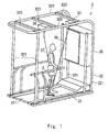
- FIG. 1 is a perspective view showing a schematic configuration of a walking training apparatus according to an exemplary embodiment of the present invention.
- a walking training apparatus 1 according to this exemplary embodiment is, for example, an apparatus by which a user such as a patient having hemiplegia caused by a stroke does a walking training.
- the walking training apparatus 1 includes a walking assistance apparatus 2 attached to the user's leg and a training apparatus 3 by which the user does a walking training.
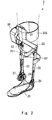
- the walking assistance apparatus 2 is, for example, attached to a diseased leg of a user who does a walking training and assists walking of the user ( Fig. 2 ).
- the walking assistance apparatus 2 includes an upper thigh frame 21, a lower thigh frame 23 connected to the upper thigh frame 21 through a knee joint part 22, a sole frame 25 connected to the lower thigh frame 23 through an ankle joint part 24, a motor unit 26 that rotationally drives the knee joint part 22, and an adjustment mechanism 27 that adjusts the movable range of the ankle joint part 24.
- the above-described configuration of the walking assistance apparatus 2 is merely an example and the configuration of the walking assistance apparatus 2 is not limited to such an example.
- the walking assistance apparatus 2 may include another motor unit that rotationally drives the ankle joint part 24.
- the upper thigh frame 21 is attached to the upper thigh of the user's leg and the lower thigh frame 23 is attached to the lower thigh of the user's leg.
- the upper thigh frame 21 is, for example, equipped with an upper thigh harness 212 for fixing the upper thigh.
- the upper thigh harness 212 is fixed to the upper thigh by using, for example, Velcro (registered trademark). In this way, it is possible to prevent the walking assistance apparatus 2 from being displaced from the user's leg in the horizontal direction or the vertical direction.
- the upper thigh frame 21 is equipped with a horizontally-extending and horizontally-long first frame 211 for connecting with a wire 36 of a first pulling unit 33 (which is described later).
- the above-described connecting part of the first pulling unit 33 is merely an example and the connection of the first pulling unit 33 is not limited to such an example.
- the wire 36 of the first pulling unit 33 may be connected to the upper thigh harness 212 and the pulling point of the first pulling unit 33 can be disposed at an arbitrary position in the walking assistance apparatus 2.
- the motor unit 26 rotationally drives the knee joint part 22 according to the walking motion of the user and thereby assists the walking of the user.
- the above-described configuration of the walking assistance apparatus 2 is merely an example and the configuration of the walking assistance apparatus 2 is not limited to such an example. Any walking assistance apparatus capable of being attached to a user's leg and assisting walking of the user can be applied.
- the training apparatus 3 includes a treadmill 31, a frame main body 32, first and second pulling units 33 and 34, and a control device 35.
- the treadmill 31 rotates a ringshaped belt 311. The user gets on the belt 311 and walks on the belt 311 according to the movement of the belt 311. By doing so, the user does a walking training.
- the frame main body 32 includes two pairs of pillar frames 321 vertically disposed on the treadmill 31, a pair of lengthwise frames 322 extending in the lengthwise direction and connected to respective pillar frames 321, and three crosswise frames 323 extending in the crosswise direction and connected to each of the lengthwise frames 322.
- the configuration of the above-described frame main body 32 is not limited to this example. Any frame structure can be adopted for the frame main body 32, provided that the first and second pulling units (which are described later) can be appropriately fixed to the frame main body 32.
- the first pulling unit 33 that pulls the wire 36 upward and forward is provided.
- the first pulling unit 33 is a specific example of the first pulling means.
- the first pulling unit 33 includes, for example, a mechanism for winding up and back the wire 36, a motor that drives the mechanism, and so on.
- One end of the wire 36, which is pulled by the first pulling unit 33, is connected to the walking assistance apparatus 2.
- the first pulling unit 33 pulls the walking assistance apparatus 2 upward and forward through the wire 36.
- the vertically-upward component of the pulling force applied by the first pulling unit 33 supports the weight of the walking assistance apparatus 2.
- the horizontally-forward component of the pulling force applied by the first pulling unit 33 assists the start of swinging of the leg. In this way, the walking load of the user in the walking training can be reduced.
- the second pulling unit 34 is disposed in the rear crosswise frame 323 and pulls a wire 37 upward.
- One end of the wire 37 is connected to, for example, a belt attached to at or near the user's waist.
- the second pulling unit 34 includes, for example, a mechanism for winding up and back the wire 37, a motor that drives the mechanism, and so on.
- the second pulling unit 34 pulls the user's waist upward through the wire 37. In this way, the load on the user caused by the weight of the user himself/herself can be reduced.
- Each of the first and second pulling units 33 and 34 is connected to the control device 35 through a wiring line or the like.
- the control device 35 is a specific example of the control means.
- the control device 35 controls each of the pulling forces applied by the first and second pulling units 33 and 34, the driving of the treadmill 31, and the walking assistance apparatus 2.
- the control device 35 is formed by hardware mainly using a microcomputer including a CPU (Central Processing Unit) that performs arithmetic processing, control processing, and so on, a ROM (Read Only Memory) that stores an arithmetic program, a control program and so on to be executed by the CPU, a RAM (Random Access Memory) that stores various data and so on, and an interface unit (I/F) that externally receives and outputs signals.
- the CPU, the ROM, the RAM, and the interface unit are connected with each other through a data bus or the like.
- Fig. 3 is a block diagram showing a schematic system configuration of the control device according to this exemplary embodiment.
- the control device 35 includes, for example, a leg load relief control unit 351 that controls the first pulling unit 33, a person load relief control unit 352 that controls the second pulling unit 34, a leg control unit 353 that controls the walking assistance apparatus 2, a treadmill control unit 354 that controls the treadmill 31, a computer or a PC (Personal Computer) 355 that controls these units, and an operation panel 356 for operating the computer 355.
- the operation panel 356 displays information such as a training instruction, a training menu, and training information (such as walking speed and biological information).
- the operation panel 356 is formed, for example, as a touch panel, and a user can enter various types of information (pulling forces applied by the first and second pulling units 33 and 34) through the operation panel 356.
- the timing of the start of swinging of a leg in walking is also the timing at which the user reverses his/her leg's motion from the backward motion to the forward motion. Therefore, the leg to which the walking assistance apparatus is attached receives the backward inertial force from the walking assistance apparatus at this reverse timing.
- the related art walking training apparatus reduces the load on user's walking caused by the gravitational force of the walking assistance apparatus, it does not reduce the above-described load caused by the inertial force. Therefore, an excessive load is exerted on the leg of the user (in particular, a patient having hemiplegia caused by a stroke or the like) at the start of swinging of the leg in the walking.
- control device 35 controls the first pulling unit 33 so that the vertically-upward component f2 of the pulling force f applied by the first pulling unit 33 reduces the gravitational force of the walking assistance apparatus. Further, the control device 35 controls the first pulling unit 33 so that the first pulling unit 33 increases the pulling force f and thereby generates an additional pulling force at the start of swinging of the leg to which the walking assistance apparatus 2 is attached or during the swinging period of the leg.
- the load caused by the gravitational force of the walking assistance apparatus 2 on the walking of the user can be reduced by controlling the first pulling unit 33 so that the vertically-upward component f2 of the pulling force f applied by the first pulling unit 33 reduces the gravitational force of the walking assistance apparatus.
- the load caused by the inertial force of the walking assistance apparatus 2 can be reduced at the start of swinging of the leg or during the swinging period of the leg by increasing the pulling force f applied by the first pulling unit 33 and thereby increasing its horizontally-forward component f1 at the start of swinging of the leg or during the swinging period of the leg. That is, the load exerted on the leg to which the walking assistance apparatus 2 is attached can be reduced at the start of swinging of that leg or during the swinging period of the leg.
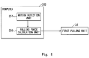
- FIG. 4 is a block diagram showing a schematic system configuration of a computer according to this exemplary embodiment.
- a computer 355 according to this exemplary embodiment includes a motion detection unit 357 that detects the start of forward swinging of a leg to which the walking assistance apparatus 2 is attached and a pulling force calculation unit 358 that calculates a pulling force command value for the first pulling unit 33.
- the motion detection unit 357 detects information about the motion or the position of the leg or the foot to which the walking assistance apparatus 2 is attached by using a camera (a specific example of the image pickup means).
- the motion detection unit 357 detects the start of forward swinging of the leg to which the walking assistance apparatus 2 is attached based on the detected information.
- the motion detection unit 357 detects information about the motion or the position of the walking assistance apparatus 2 by using a camera and detects the start of forward swinging of the leg to which the walking assistance apparatus 2 is attached based on the detected information.
- the motion detection unit 357 detects the start of forward swinging of the leg to which the walking assistance apparatus 2 is attached based on a change in the angle of the knee joint part over time detected by an angle sensor (a specific example of the knee angle detection means) provided in the knee joint part 22 of the walking assistance apparatus 2. More specifically, the motion detection unit 357 detects the start of swinging of the leg when the motion detection unit 357 determines that the detected angle of the knee joint part enters a change range corresponding to a swinging starting motion based on a change in the angle of the knee joint part over time detected by the angle sensor.
- an angle sensor a specific example of the knee angle detection means
- the motion detection unit (a specific example of the speed detection means) 357 detects the moving speed of the belt 311 of the treadmill 31 and calculates the walking cycle of the user based on the detected moving speed. Then, the motion detection unit 357 detects the start of forward swinging of the leg to which the walking assistance apparatus 2 is attached based on the calculated walking cycle of the user.
- the relation between the walking cycle and the moving speed of the belt 311 of the treadmill 31 can be experimentally obtained in advance (for example, the walking cycle is expressed as a monotonous phenomenon function including the moving speed of the belt 311 of the training apparatus 3 as its variable). Note that the above-described method for detecting the start of swinging of the leg is merely an example.
- the detection method is not limited to such an example and an arbitrary detection method can be applied.
- the motion detection unit 357 detects the start of forward swinging of the leg to which the walking assistance apparatus 2 is attached, the motion detection unit 357 outputs a detection signal to the pulling force calculation unit 358.
- the pulling force calculation unit 358 calculates a pulling force command value for the first pulling unit 33 and outputs the calculated pulling force command value to the first pulling unit 33.
- the first pulling unit 33 pulls the wire 36 of the walking assistance apparatus 2 according to the pulling force command value output from the pulling force calculation unit 358.
- the vertically-upward component f2 of the pulling force f applied by the first pulling unit 33 supports the weight of the walking assistance apparatus 2.
- the horizontally-forward component f1 of the pulling force f applied by the first pulling unit 33 assists the start of swinging of the leg.
- the pulling force command value is set so that, for the normal walking motion of the user, the vertically-upward component f2 of the pulling force f supports the weight of the walking assistance apparatus 2 and the horizontally-forward component f1 of the pulling force f optimally assists the start of swinging of the leg.
- the leg receives the backward inertial force from the walking assistance apparatus 2 at the start of swinging of the leg in the walking and hence a load higher than that exerted in a normal walking motion is exerted on the leg at the start of swinging of the leg.
- the pulling force calculation unit 358 when the pulling force calculation unit 358 according to this exemplary embodiment receives a detection signal from the motion detection unit 357, the pulling force calculation unit 358 increases the pulling force command value from its normal value for a predetermined time period ( Fig. 5 ).
- the pulling force f for the first pulling unit 33 is increased only when the leg receives the inertial force at the start of swinging of the leg. In this way, the load caused by the inertial force at the start of swinging of the leg can be reduced.
- the pulling force calculation unit 358 When the pulling force calculation unit 358 receives a detection signal from the motion detection unit 357, the pulling force calculation unit 358 sharply increases the pulling force command value in a short time, for example, in a pulsed manner.
- the increment of the pulling force command value may be set, for example, based on the inertial force of the walking assistance apparatus 2 calculated from the moving speed of the belt 311 of the treadmill 31.
- the pulling force calculation unit 358 outputs the normal pulling force command value to the first pulling unit 33.
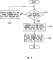
- Fig. 6 is a flowchart showing a flow of a walking training method according to this exemplary embodiment.
- the motion detection unit 357 detects the start of forward swinging of the leg to which the walking assistance apparatus 2 is attached based on, for example, a change in the pressure distribution on the sole over time (step S101).
- the pulling force calculation unit 358 increases the pulling force command value and outputs the increased pulling force command value to the first pulling unit 33 (step S102).
- the pulling force calculation unit 358 outputs the normal pulling force command value to the first pulling unit 33 (step S103). The process then returns to the above-described step S101.
- the pulling force calculation unit 358 outputs the normal pulling force command value to the first pulling unit 33 (step S104).
- the walking training apparatus controls the first pulling unit 33 so that the vertically-upward component f2 of the pulling force f applied by the first pulling unit 33 reduces the gravitational force of the walking assistance apparatus.
- the vertically-upward component f2 of the pulling force f applied by the first pulling unit 33 is made equal to the gravitational force of the walking assistance apparatus 2 or equal to a half of the gravitational force of the walking assistance apparatus 2.
- the pulling force f applied by the first pulling unit 33 is increased at the start of swinging of the leg. In this way, it is possible to reduce the load caused by the inertial force of the walking assistance apparatus 2 at the start of swinging of the leg and thereby reduce the load exerted on the leg at the start of swinging of the leg.
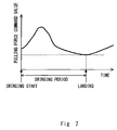
- the pulling force calculation unit 358 may increase the pulling force command value and then gradually decrease the pulling force command value( Fig. 7 ). For example, the pulling force calculation unit 358 increases the pulling force command value in a pulsed manner when the start of swinging of the leg is detected. After that, the pulling force calculation unit 358 gradually decreases the pulling force command value and returns the pulling force command value to the normal value when the swinging period has been finished (when the sole frame 25 lands on the ground). In this case, the pulling force calculation unit 358 may increase the pulling force command value as the pulling force exerted on the wire 36 of the walking assistance apparatus 2 increases during this swinging period.
- the above-described exemplary embodiment may have a configuration in which a third pulling unit 38 that pulls the walking assistance apparatus upward and backward through a wire 39 is provided in the crosswise frame 323 of the frame main body 32 ( Fig. 8 ).
- the third pulling unit 38 is a specific example of the second pulling means.
- the resultant force of the vertically-upward components of the pulling forces applied by the first and third pulling units 33 and 38 supports the weight of the walking assistance apparatus 2. Further, the resultant force of the horizontal components of the pulling forces applied by the first and third pulling units 33 and 38 assists the start of swinging of the leg.
- the present invention is not limited to such a configuration and method.
- the pulling force command value for the third pulling unit 38 may be changed in a manner similar to the pulling force command value for the first pulling unit 33.
- the pulling force calculation unit 358 changes the pulling force command values for the first and third pulling units 33 and 38 and thereby increases the horizontally-forward components of the pulling forces applied by the first and third pulling units 33 and 38 at the start of swinging of the leg.
- the vertically-upward components and the horizontally-forward components of the pulling forces applied by the first and third pulling units 33 and 38 can be accurately controlled independently of each other.
- control device 35 may control the first and third pulling units 33 and 38 so that the horizontal components of the pulling forces applied by the first and third pulling units 33 and 38 are increased. In this way, the load caused by the inertial force of the walking assistance apparatus 2 at the start of swing-back of the leg can also be reduced.
- the training apparatus 3 may not include the frame main body 32.
- the first and second pulling units may be, for example, disposed (or mounted) on the wall or the ceiling.
- the wire 36 of the first pulling unit 33 is connected to the walking assistance apparatus 2 in the above-described exemplary embodiment, the present invention is not limited to such a configuration.
- the wire 36 of the first pulling unit 33 may be connected to the user's leg through a fixture such as a belt and ring. Further, the wire 36 of the first pulling unit 33 may be connected to both the walking assistance apparatus 2 and the user's leg.
- the present invention is not limited to such a configuration.
- the present invention may be applied to a configuration in which a user outfitted with the walking assistance apparatus 2 walks on a stationary road surface and the first pulling unit 33 is moved according to the movement of the user.
Landscapes
- Health & Medical Sciences (AREA)
- General Health & Medical Sciences (AREA)
- Physical Education & Sports Medicine (AREA)
- Life Sciences & Earth Sciences (AREA)
- Engineering & Computer Science (AREA)
- Animal Behavior & Ethology (AREA)
- Veterinary Medicine (AREA)
- Public Health (AREA)
- Orthopedic Medicine & Surgery (AREA)
- Epidemiology (AREA)
- Pain & Pain Management (AREA)
- Rehabilitation Therapy (AREA)
- Biophysics (AREA)
- Vascular Medicine (AREA)
- Cardiology (AREA)
- Physics & Mathematics (AREA)
- Molecular Biology (AREA)
- Biomedical Technology (AREA)
- Heart & Thoracic Surgery (AREA)
- Medical Informatics (AREA)
- Pathology (AREA)
- Surgery (AREA)
- Computer Vision & Pattern Recognition (AREA)
- Dentistry (AREA)
- Oral & Maxillofacial Surgery (AREA)
- Physiology (AREA)
- Psychiatry (AREA)
- Social Psychology (AREA)
- Human Computer Interaction (AREA)
- General Physics & Mathematics (AREA)
- Multimedia (AREA)
- Theoretical Computer Science (AREA)
- Rehabilitation Tools (AREA)
Abstract
Description
- The present invention relates to a walking training apparatus by which a user does a walking training and a walking training method therefor.
- For example, the applicant of the present application has proposed a walking training apparatus including a walking assistance apparatus that is attached to a leg of a user and assists walking performed by the user (see Japanese Unexamined Patent Application Publication
JP 2015-223 294 A - Here, assume a configuration in which first pulling means for pulling one of the walking assistance apparatus and a user's leg upward and forward, and second pulling means for pulling one of the walking assistance apparatus and the user's leg upward and forward are further added, and the resultant force of the vertically-upward components of the pulling forces applied by the first and second pulling means is roughly equal to the weight of the walking assistance apparatus so that the load caused by the gravitational force of the walking assistance apparatus exerted on the user's leg is reduced. The present inventors have found that the following problem occurs in this configuration. That is, the timing of the start of swinging of a leg in walking is also the timing at which the user reverses his/her leg's motion from the backward motion to the forward motion. Therefore, the leg to which the walking assistance apparatus is attached receives the backward inertial force from the walking assistance apparatus at this reverse timing. However, although the above-described walking training apparatus reduces the load on user's walking caused by the gravitational force of the walking assistance apparatus, it does not reduce the above-described load caused by the inertial force. Therefore, an excessive load is exerted on the leg to which the walking assistance apparatus is attached at the start of swinging of that leg. Meanwhile, it is conceivable to simply increase the pulling force applied by the pulling means in order to reduce the above-described load. However, in such a case, the leg could be easily lifted inadvertently, making the landing of the leg unstable and preventing the user from doing a stable walking training.
- The present invention has been made in view of the above-described problems and one of the main objects thereof is to provide a walking training apparatus and a walking training method therefor capable of reducing the load exerted on a leg to which a walking assistance apparatus is attached at the start of swinging of that leg or during the swinging period thereof.
- The above object is solved with a walking training apparatus comprising a walking assistance apparatus attachable to a leg of a user, the walking assistance apparatus being configured to assist walking of the user; first pulling means for pulling the leg upward and forward directly or through the walking assistance apparatus; and control means adapted to control the first pulling means so that a vertically-upward component of a normal pulling force applied by the first pulling means reduces a weight of the walking assistance apparatus, wherein the walking training apparatus further comprises a motion detection unit adapted to detect the start of forward swinging of the leg, wherein the control means is adapted to make the first pulling means generate an additional pulling force in addition to the normal pulling force when the start of forward swinging of the leg is detected by the motion detection unit. According to this aspect, the load exerted on the leg to which the walking assistance apparatus is attached can be reduced at the start of swinging of that leg or during the swinging period thereof.
- The walking training apparatus may further comprise second pulling means for pulling the leg upward and backward directly or through the walking assistance apparatus, wherein the control means may be adapted to control the first and second pulling means so that a resultant force of vertically-upward components of normal pulling forces applied by the first and second pulling means reduces the weight of the walking assistance apparatus; and may control the first and second pulling means so that the first and second pulling means generate the additional pulling force in addition to the normal pulling forces when the start of forward swinging of the leg is detected by the motion detection unit. According to this aspect, the vertically-upward components and the horizontally-forward components of the pulling forces applied by the first and second means can be accurately controlled independently of each other. As a result, it is possible to, while reducing the load caused by the gravitational force of the walking assistance apparatus, reduce the load exerted on the leg to which the walking assistance apparatus is attached at the start of swinging of that leg or during the swinging period thereof in a more optimal manner.
- The walking training apparatus may further comprise an image pickup means for taking an image of the leg of the user, wherein the motion detection unit is adapted to detect information about the motion or the position of the leg or of the foot to which the walking assistance apparatus is attached or of the walking assistance apparatus by using the image pickup means and to detect the start of forward swinging of the leg based on the detected information.
- The walking training apparatus may further comprise a knee angle detection means for detecting an angle of a knee joint part of the walking assistance apparatus, wherein the motion detection unit is adapted to detect the start of the forward swinging of the leg based on a change in the angle of the knee joint part over time detected by the knee angle detection means.
- The motion detection unit may be adapted to detect the start of forward swinging of the leg when the motion detection unit determines that the detected angle of the knee joint part enters a change rate corresponding to a swinging starting motion based on a change in the angle of the knee part over the time detected by the knee angle detection means.
- The walking training apparatus may further comprise a treadmill for rotating a belt on which the user can walk, wherein the motion detection unit may be adapted to detect the moving speed of belt and to calculate a walking cycle of the user based on the detected moving speed, wherein the motion detecting unit may be adapted to detect the start of forward swinging of the leg based on the calculated walking cycle of the user.
- The motion detection unit may be adapted to detect the start of forward swinging of the leg based on a change in the pressure distribution on a sole of the walking assistance apparatus.
- The control means may be adapted to make the first pulling means generate the additional pulling force during a swinging period of the leg in a user's walking motion by using information detected by at least one of the knee angle detection means and the image pickup means.
- According to these aspects, it is possible to detect the start of swinging of the leg to which the walking assistance apparatus is attached or the swinging period thereof by using the information detected by at least one of the joint angle detection means, the image pickup means, and the speed detection means and thereby reduce the load exerted on the leg at the start of swinging of the leg or during the swinging period thereof.
- According to these aspects, it is possible to detect the start of swinging of the leg to which the walking assistance apparatus is attached or the swinging period thereof by using the information detected by at least one of the joint angle detection means, the image pickup means, and the speed detection means, and accurately control the vertically-upward components and the horizontally-forward components of the pulling forces applied by the first and second means independently of each other at the start of swinging of the leg or during the swinging period thereof. Therefore, the load exerted on the leg can be reduced even further.
- The above object is also solved by a walking training method for a walking training apparatus, the walking training apparatus comprising: a walking assistance apparatus attachable to a leg of a user, the walking assistance apparatus being configured to assist walking of the user; first pulling means for pulling the leg upward and forward directly or through the walking assistance apparatus; control means; and a motion detection unit; the method comprising the steps of detecting the start of forward swinging of the leg, controlling the first pulling means so that a vertically-upward component of a normal pulling force applied by the first pulling means reduces a weight of the walking assistance apparatus, and generating an additional pulling force in addition to the normal pulling force by the first pulling means when the start of forward swinging of the leg is detected by the motion detection unit.
According to this aspect, the load exerted on the leg to which the walking assistance apparatus is attached can be reduced at the start of swinging of that leg or during the swinging period thereof - According to the present invention, it is possible to provide a walking training apparatus and a walking training method therefor capable of reducing the load exerted on a leg to which a walking assistance apparatus is attached at the start of swinging of that leg or during the swinging period thereof.
- The above and other objects, features and advantages of the present invention will become more fully understood from the detailed description given hereinbelow and the accompanying drawings which are given by way of illustration only, and thus are not to be considered as limiting the present invention.
-
-
Fig. 1 is a perspective view showing a schematic configuration of a walking training apparatus according to an exemplary embodiment of the present invention; -
Fig. 2 is a perspective view showing a schematic configuration of a walking assistance apparatus; -
Fig. 3 is a block diagram showing a schematic system configuration of a control device according to an exemplary embodiment of the present invention; -
Fig. 4 is a block diagram showing a schematic system configuration of a computer according to an exemplary embodiment of the present invention; -
Fig. 5 shows variations in a pulling force command value at the start of swinging of a leg; -
Fig. 6 is a flowchart showing a flow of a walking training method according to an exemplary embodiment of the present invention; -
Fig. 7 shows variations in a pulling force command value at the start of swinging of a leg; and -
Fig. 8 is a block diagram showing a schematic system configuration of a control device according to an exemplary embodiment of the present invention. - Exemplary embodiments according to the present invention are explained hereinafter with reference to the drawings.
-
Fig. 1 is a perspective view showing a schematic configuration of a walking training apparatus according to an exemplary embodiment of the present invention. A walking training apparatus 1 according to this exemplary embodiment is, for example, an apparatus by which a user such as a patient having hemiplegia caused by a stroke does a walking training. The walking training apparatus 1 includes awalking assistance apparatus 2 attached to the user's leg and atraining apparatus 3 by which the user does a walking training. - The
walking assistance apparatus 2 is, for example, attached to a diseased leg of a user who does a walking training and assists walking of the user (Fig. 2 ). Thewalking assistance apparatus 2 includes anupper thigh frame 21, alower thigh frame 23 connected to theupper thigh frame 21 through a kneejoint part 22, asole frame 25 connected to thelower thigh frame 23 through an anklejoint part 24, amotor unit 26 that rotationally drives the kneejoint part 22, and anadjustment mechanism 27 that adjusts the movable range of the anklejoint part 24. Note that the above-described configuration of thewalking assistance apparatus 2 is merely an example and the configuration of thewalking assistance apparatus 2 is not limited to such an example. For example, thewalking assistance apparatus 2 may include another motor unit that rotationally drives the anklejoint part 24. - The
upper thigh frame 21 is attached to the upper thigh of the user's leg and thelower thigh frame 23 is attached to the lower thigh of the user's leg. Theupper thigh frame 21 is, for example, equipped with anupper thigh harness 212 for fixing the upper thigh. Theupper thigh harness 212 is fixed to the upper thigh by using, for example, Velcro (registered trademark). In this way, it is possible to prevent thewalking assistance apparatus 2 from being displaced from the user's leg in the horizontal direction or the vertical direction. Theupper thigh frame 21 is equipped with a horizontally-extending and horizontally-longfirst frame 211 for connecting with awire 36 of a first pulling unit 33 (which is described later). - Note that the above-described connecting part of the
first pulling unit 33 is merely an example and the connection of thefirst pulling unit 33 is not limited to such an example. For example, thewire 36 of thefirst pulling unit 33 may be connected to theupper thigh harness 212 and the pulling point of thefirst pulling unit 33 can be disposed at an arbitrary position in thewalking assistance apparatus 2. - The
motor unit 26 rotationally drives the kneejoint part 22 according to the walking motion of the user and thereby assists the walking of the user. Note that the above-described configuration of thewalking assistance apparatus 2 is merely an example and the configuration of thewalking assistance apparatus 2 is not limited to such an example. Any walking assistance apparatus capable of being attached to a user's leg and assisting walking of the user can be applied. - The
training apparatus 3 includes atreadmill 31, a framemain body 32, first andsecond pulling units control device 35. Thetreadmill 31 rotates aringshaped belt 311. The user gets on thebelt 311 and walks on thebelt 311 according to the movement of thebelt 311. By doing so, the user does a walking training. - The frame
main body 32 includes two pairs of pillar frames 321 vertically disposed on thetreadmill 31, a pair oflengthwise frames 322 extending in the lengthwise direction and connected to respective pillar frames 321, and three crosswiseframes 323 extending in the crosswise direction and connected to each of the lengthwise frames 322. Note that the configuration of the above-described framemain body 32 is not limited to this example. Any frame structure can be adopted for the framemain body 32, provided that the first and second pulling units (which are described later) can be appropriately fixed to the framemain body 32. - In the front crosswise
frame 323, the first pullingunit 33 that pulls thewire 36 upward and forward is provided. The first pullingunit 33 is a specific example of the first pulling means. The first pullingunit 33 includes, for example, a mechanism for winding up and back thewire 36, a motor that drives the mechanism, and so on. One end of thewire 36, which is pulled by the first pullingunit 33, is connected to thewalking assistance apparatus 2. The first pullingunit 33 pulls the walkingassistance apparatus 2 upward and forward through thewire 36. - The vertically-upward component of the pulling force applied by the first pulling
unit 33 supports the weight of the walkingassistance apparatus 2. The horizontally-forward component of the pulling force applied by the first pullingunit 33 assists the start of swinging of the leg. In this way, the walking load of the user in the walking training can be reduced. - The second pulling
unit 34 is disposed in the rear crosswiseframe 323 and pulls awire 37 upward. One end of thewire 37 is connected to, for example, a belt attached to at or near the user's waist. The second pullingunit 34 includes, for example, a mechanism for winding up and back thewire 37, a motor that drives the mechanism, and so on. The second pullingunit 34 pulls the user's waist upward through thewire 37. In this way, the load on the user caused by the weight of the user himself/herself can be reduced. Each of the first and second pullingunits control device 35 through a wiring line or the like. - The
control device 35 is a specific example of the control means. Thecontrol device 35 controls each of the pulling forces applied by the first and second pullingunits treadmill 31, and the walkingassistance apparatus 2. For example, thecontrol device 35 is formed by hardware mainly using a microcomputer including a CPU (Central Processing Unit) that performs arithmetic processing, control processing, and so on, a ROM (Read Only Memory) that stores an arithmetic program, a control program and so on to be executed by the CPU, a RAM (Random Access Memory) that stores various data and so on, and an interface unit (I/F) that externally receives and outputs signals. The CPU, the ROM, the RAM, and the interface unit are connected with each other through a data bus or the like. -
Fig. 3 is a block diagram showing a schematic system configuration of the control device according to this exemplary embodiment. - The
control device 35 includes, for example, a leg loadrelief control unit 351 that controls the first pullingunit 33, a person loadrelief control unit 352 that controls the second pullingunit 34, aleg control unit 353 that controls the walkingassistance apparatus 2, atreadmill control unit 354 that controls thetreadmill 31, a computer or a PC (Personal Computer) 355 that controls these units, and anoperation panel 356 for operating thecomputer 355. Theoperation panel 356 displays information such as a training instruction, a training menu, and training information (such as walking speed and biological information). Theoperation panel 356 is formed, for example, as a touch panel, and a user can enter various types of information (pulling forces applied by the first and second pullingunits 33 and 34) through theoperation panel 356. - Incidentally, the timing of the start of swinging of a leg in walking is also the timing at which the user reverses his/her leg's motion from the backward motion to the forward motion. Therefore, the leg to which the walking assistance apparatus is attached receives the backward inertial force from the walking assistance apparatus at this reverse timing. However, although the related art walking training apparatus reduces the load on user's walking caused by the gravitational force of the walking assistance apparatus, it does not reduce the above-described load caused by the inertial force. Therefore, an excessive load is exerted on the leg of the user (in particular, a patient having hemiplegia caused by a stroke or the like) at the start of swinging of the leg in the walking. Meanwhile, it is conceivable to simply increase the pulling force applied by the pulling unit in order to reduce the above-described load. However, in such a case, the leg could be easily lifted inadvertently, making the landing of the leg unstable and preventing the user from doing a stable walking training.
- In contrast to this, the
control device 35 according to this exemplary embodiment controls the first pullingunit 33 so that the vertically-upward component f2 of the pulling force f applied by the first pullingunit 33 reduces the gravitational force of the walking assistance apparatus. Further, thecontrol device 35 controls the first pullingunit 33 so that the first pullingunit 33 increases the pulling force f and thereby generates an additional pulling force at the start of swinging of the leg to which thewalking assistance apparatus 2 is attached or during the swinging period of the leg. - As described above, according to this exemplary embodiment, the load caused by the gravitational force of the walking
assistance apparatus 2 on the walking of the user can be reduced by controlling the first pullingunit 33 so that the vertically-upward component f2 of the pulling force f applied by the first pullingunit 33 reduces the gravitational force of the walking assistance apparatus. Further, according to this exemplary embodiment, the load caused by the inertial force of the walkingassistance apparatus 2 can be reduced at the start of swinging of the leg or during the swinging period of the leg by increasing the pulling force f applied by the first pullingunit 33 and thereby increasing its horizontally-forward component f1 at the start of swinging of the leg or during the swinging period of the leg. That is, the load exerted on the leg to which thewalking assistance apparatus 2 is attached can be reduced at the start of swinging of that leg or during the swinging period of the leg. -
Fig. 4 is a block diagram showing a schematic system configuration of a computer according to this exemplary embodiment. Acomputer 355 according to this exemplary embodiment includes amotion detection unit 357 that detects the start of forward swinging of a leg to which thewalking assistance apparatus 2 is attached and a pullingforce calculation unit 358 that calculates a pulling force command value for the first pullingunit 33. - For example, the
motion detection unit 357 detects information about the motion or the position of the leg or the foot to which thewalking assistance apparatus 2 is attached by using a camera (a specific example of the image pickup means). Themotion detection unit 357 detects the start of forward swinging of the leg to which thewalking assistance apparatus 2 is attached based on the detected information. Alternatively, themotion detection unit 357 detects information about the motion or the position of the walkingassistance apparatus 2 by using a camera and detects the start of forward swinging of the leg to which thewalking assistance apparatus 2 is attached based on the detected information. - The
motion detection unit 357 detects the start of forward swinging of the leg to which thewalking assistance apparatus 2 is attached based on a change in the angle of the knee joint part over time detected by an angle sensor (a specific example of the knee angle detection means) provided in the kneejoint part 22 of the walkingassistance apparatus 2. More specifically, themotion detection unit 357 detects the start of swinging of the leg when themotion detection unit 357 determines that the detected angle of the knee joint part enters a change range corresponding to a swinging starting motion based on a change in the angle of the knee joint part over time detected by the angle sensor. - The motion detection unit (a specific example of the speed detection means) 357 detects the moving speed of the
belt 311 of thetreadmill 31 and calculates the walking cycle of the user based on the detected moving speed. Then, themotion detection unit 357 detects the start of forward swinging of the leg to which thewalking assistance apparatus 2 is attached based on the calculated walking cycle of the user. The relation between the walking cycle and the moving speed of thebelt 311 of thetreadmill 31 can be experimentally obtained in advance (for example, the walking cycle is expressed as a monotonous phenomenon function including the moving speed of thebelt 311 of thetraining apparatus 3 as its variable). Note that the above-described method for detecting the start of swinging of the leg is merely an example. That is, the detection method is not limited to such an example and an arbitrary detection method can be applied. When themotion detection unit 357 detects the start of forward swinging of the leg to which thewalking assistance apparatus 2 is attached, themotion detection unit 357 outputs a detection signal to the pullingforce calculation unit 358. - The pulling
force calculation unit 358 calculates a pulling force command value for the first pullingunit 33 and outputs the calculated pulling force command value to the first pullingunit 33. The first pullingunit 33 pulls thewire 36 of the walkingassistance apparatus 2 according to the pulling force command value output from the pullingforce calculation unit 358. At this point, the vertically-upward component f2 of the pulling force f applied by the first pullingunit 33 supports the weight of the walkingassistance apparatus 2. The horizontally-forward component f1 of the pulling force f applied by the first pullingunit 33 assists the start of swinging of the leg. That is, the pulling force command value is set so that, for the normal walking motion of the user, the vertically-upward component f2 of the pulling force f supports the weight of the walkingassistance apparatus 2 and the horizontally-forward component f1 of the pulling force f optimally assists the start of swinging of the leg. - However, as described previously, the leg receives the backward inertial force from the walking
assistance apparatus 2 at the start of swinging of the leg in the walking and hence a load higher than that exerted in a normal walking motion is exerted on the leg at the start of swinging of the leg. To cope with this, when the pullingforce calculation unit 358 according to this exemplary embodiment receives a detection signal from themotion detection unit 357, the pullingforce calculation unit 358 increases the pulling force command value from its normal value for a predetermined time period (Fig. 5 ). As described above, the pulling force f for the first pullingunit 33 is increased only when the leg receives the inertial force at the start of swinging of the leg. In this way, the load caused by the inertial force at the start of swinging of the leg can be reduced. - When the pulling
force calculation unit 358 receives a detection signal from themotion detection unit 357, the pullingforce calculation unit 358 sharply increases the pulling force command value in a short time, for example, in a pulsed manner. Note that the increment of the pulling force command value may be set, for example, based on the inertial force of the walkingassistance apparatus 2 calculated from the moving speed of thebelt 311 of thetreadmill 31. When a predetermined time has elapsed after the start of swinging of the leg is detected, the pullingforce calculation unit 358 outputs the normal pulling force command value to the first pullingunit 33. -
Fig. 6 is a flowchart showing a flow of a walking training method according to this exemplary embodiment. - The
motion detection unit 357 detects the start of forward swinging of the leg to which thewalking assistance apparatus 2 is attached based on, for example, a change in the pressure distribution on the sole over time (step S101). - When the
motion detection unit 357 detects the start of forward swinging of the leg to which thewalking assistance apparatus 2 is attached (Yes at step S101), the pullingforce calculation unit 358 increases the pulling force command value and outputs the increased pulling force command value to the first pulling unit 33 (step S102). On the other hand, when themotion detection unit 357 does not detect the start of forward swinging of the leg to which thewalking assistance apparatus 2 is attached (No at step S101), the pullingforce calculation unit 358 outputs the normal pulling force command value to the first pulling unit 33 (step S103). The process then returns to the above-described step S101. - When a predetermined time has elapsed after the start of swinging of the leg is detected, the pulling
force calculation unit 358 outputs the normal pulling force command value to the first pulling unit 33 (step S104). - As described above, the walking training apparatus according to this exemplary embodiment controls the first pulling
unit 33 so that the vertically-upward component f2 of the pulling force f applied by the first pullingunit 33 reduces the gravitational force of the walking assistance apparatus. For example, the vertically-upward component f2 of the pulling force f applied by the first pullingunit 33 is made equal to the gravitational force of the walkingassistance apparatus 2 or equal to a half of the gravitational force of the walkingassistance apparatus 2. - Further, the pulling force f applied by the first pulling
unit 33 is increased at the start of swinging of the leg. In this way, it is possible to reduce the load caused by the inertial force of the walkingassistance apparatus 2 at the start of swinging of the leg and thereby reduce the load exerted on the leg at the start of swinging of the leg. - Note that the present invention is not limited to the above-described exemplary embodiments, and various modifications can be made without departing from the spirit and scope of the present invention.
- In the above-described exemplary embodiment, when the
motion detection unit 357 of thecomputer 355 detects the start of forward swinging of the leg to which thewalking assistance apparatus 2 is attached, the pullingforce calculation unit 358 may increase the pulling force command value and then gradually decrease the pulling force command value(Fig. 7 ). For example, the pullingforce calculation unit 358 increases the pulling force command value in a pulsed manner when the start of swinging of the leg is detected. After that, the pullingforce calculation unit 358 gradually decreases the pulling force command value and returns the pulling force command value to the normal value when the swinging period has been finished (when thesole frame 25 lands on the ground). In this case, the pullingforce calculation unit 358 may increase the pulling force command value as the pulling force exerted on thewire 36 of the walkingassistance apparatus 2 increases during this swinging period. - In this way, it is possible to continuously add a pulling force larger than the normal pulling force in the swinging direction during the swinging period (the period in which the user is swinging his/her leg). As a result, it is possible to reduce not only the load caused by the inertial force but also the overall load of the swinging motion.
- The above-described exemplary embodiment may have a configuration in which a third pulling
unit 38 that pulls the walking assistance apparatus upward and backward through awire 39 is provided in thecrosswise frame 323 of the frame main body 32 (Fig. 8 ). The third pullingunit 38 is a specific example of the second pulling means. The resultant force of the vertically-upward components of the pulling forces applied by the first and third pullingunits assistance apparatus 2. Further, the resultant force of the horizontal components of the pulling forces applied by the first and third pullingunits - The pulling
force calculation unit 358 outputs a pulling force command value that makes the resultant force of the vertically-upward components of the pulling forces applied by the first and third pullingunits assistance apparatus 2 to the first and third pullingunits force calculation unit 358 receives a detection signal from themotion detection unit 357, the pullingforce calculation unit 358 increases the pulling force command value from its normal value for a predetermined time period and outputs the increased pulling force command value to the first pullingunit 33. At this point, the pullingforce calculation unit 358 is outputting the normal pulling force command value (pulling force command value = constant) to the third pullingunit 38. However, the present invention is not limited to such a configuration and method. That is, the pulling force command value for the third pullingunit 38 may be changed in a manner similar to the pulling force command value for the first pullingunit 33. In other words, the pullingforce calculation unit 358 changes the pulling force command values for the first and third pullingunits units units walking assistance apparatus 2 is attached at the start of swinging of that leg in a more optimal manner. - Further, when the start of swing-back of the leg to which the
walking assistance apparatus 2 is attached in the backward direction is detected, thecontrol device 35 may control the first and third pullingunits units assistance apparatus 2 at the start of swing-back of the leg can also be reduced. - In the above-described exemplary embodiment, the
training apparatus 3 may not include the framemain body 32. In such a case, the first and second pulling units may be, for example, disposed (or mounted) on the wall or the ceiling. - Although the
wire 36 of the first pullingunit 33 is connected to thewalking assistance apparatus 2 in the above-described exemplary embodiment, the present invention is not limited to such a configuration. For example, thewire 36 of the first pullingunit 33 may be connected to the user's leg through a fixture such as a belt and ring. Further, thewire 36 of the first pullingunit 33 may be connected to both thewalking assistance apparatus 2 and the user's leg. - Although the user outfitted with the walking
assistance apparatus 2 walks on thetreadmill 31 in the above-described exemplary embodiment, the present invention is not limited to such a configuration. The present invention may be applied to a configuration in which a user outfitted with the walkingassistance apparatus 2 walks on a stationary road surface and the first pullingunit 33 is moved according to the movement of the user. - From the invention thus described, it will be obvious that the embodiments of the invention may be varied in many ways. Such variations are not to be regarded as a departure from the scope of the invention, and all such modifications as would be obvious to one skilled in the art are intended for inclusion within the scope of the following claims.
Claims (10)
- A walking training apparatus (1) comprising:a walking assistance apparatus (2) attachable to a leg of a user, the walking assistance apparatus (2) being configured to assist walking of the user;first pulling means (33) for pulling the leg upward and forward directly or through the walking assistance apparatus (2); andcontrol means (35) adapted to control the first pulling means (33) so that a vertically-upward component of a normal pulling force applied by the first pulling means (33) reduces a weight of the walking assistance apparatus (2), wherein
the walking training apparatus (1) further comprises a motion detection unit (357) adapted to detect the start of forward swinging of the leg, whereinthe control means (35) is adapted to make the first pulling means (33) generate an additional pulling force in addition to the normal pulling force when the start of forward swinging of the leg is detected by the motion detection unit (357). - The walking training apparatus (1) according to Claim 1, further comprising
an image pickup means for taking an image of the leg of the user, wherein
the motion detection unit (357) is adapted to detect information about the motion or the position of the leg or of the foot to which the walking assistance apparatus (2) is attached or of the walking assistance apparatus (2) by using the image pickup means and to detect the start of forward swinging of the leg based on the detected information. - The walking training apparatus (1) according to Claim 1 or 2, further comprising
a knee angle detection means for detecting an angle of a knee joint part (22) of the walking assistance apparatus (2), wherein
the motion detection unit (357) is adapted to detect the start of the forward swinging of the leg based on a change in the angle of the knee joint part over time detected by the knee angle detection means. - The walking training apparatus (1) according to claim 3, wherein
motion detection unit (357) is adapted to detect the start of forward swinging of the leg when the motion detection unit (357) determines that the detected angle of the knee joint part enters a change rate corresponding to a swinging starting motion based on a change in the angle of the knee part (22) over the time detected by the knee angle detection means. - The walking training apparatus (1) according to any one of Claims 1 to 4, further comprising
a treadmill (31) for rotating a belt (311) on which the user can walk, wherein
the motion detection unit (357) is adapted to detect the moving speed of belt (311) and to calculate a walking cycle of the user based on the detected moving speed, wherein
the motion detecting unit (357) is adapted to detect the start of forward swinging of the leg based on the calculated walking cycle of the user. - The walking training apparatus (1) according to Claim 1, wherein
the motion detection unit (357) is adapted to detect the start of forward swinging of the leg based on a change in the pressure distribution on a sole of the walking assistance apparatus (2). - The walking training apparatus (1) according to any one of Claims 1 to 6, wherein
the control means (35) is adapted to make the first pulling means (33) generate the additional pulling force during a swinging period of the leg in a user's walking motion by using information detected by at least one of the knee angle detection means and the image pickup means. - The walking training apparatus (1) according to any one of claims 1 to 7, further comprising second pulling means (38) for pulling the leg upward and backward directly or through the walking assistance apparatus (2), wherein
the control means (35) is adapted to
control the first and second pulling means (33, 38) so that a resultant force of vertically-upward components of normal pulling forces applied by the first and second pulling means (33, 38) reduces the weight of the walking assistance apparatus (2); and
control the first and second pulling means (33, 38) so that the first and second pulling means (33, 38) generate the additional pulling force in addition to the normal pulling forces when the start of forward swinging of the leg is detected by the motion detection unit (357). - The walking training apparatus (1) according to claim 8, wherein
the motion detection unit (357) is adapted to detect a start of swing-back of the leg, and
the control means (35) is adapted to control the first and second pulling means (33, 38) so that the first and second pulling means (33, 38) generate the additional pulling force in addition to the normal pulling forces when the start of back-swing of the leg is detected by the motion detection unit (357). - A walking training method for a walking training apparatus (2), the walking training apparatus comprising:a walking assistance apparatus (2) attachable to a leg of a user, the walking assistance apparatus (2) being configured to assist walking of the user;first pulling means (33) for pulling the leg upward and forward directly or through the walking assistance apparatus (2);control means (35); anda motion detection unit (357); the method comprising the steps of detecting the start of forward swinging of the leg,controlling the first pulling means (33) so that a vertically-upward component of a normal pulling force applied by the first pulling means (33) reduces a weight of the walking assistance apparatus (2), andgenerating an additional pulling force in addition to the normal pulling force by the first pulling means (33) when the start of forward swinging of the leg is detected by the motion detection unit (357).
Applications Claiming Priority (1)
| Application Number | Priority Date | Filing Date | Title |
|---|---|---|---|
| JP2015157349A JP6369419B2 (en) | 2015-08-07 | 2015-08-07 | Walking training apparatus and method of operating the same |
Publications (2)
| Publication Number | Publication Date |
|---|---|
| EP3127527A1 true EP3127527A1 (en) | 2017-02-08 |
| EP3127527B1 EP3127527B1 (en) | 2020-04-22 |
Family
ID=56409013
Family Applications (1)
| Application Number | Title | Priority Date | Filing Date |
|---|---|---|---|
| EP16178850.0A Active EP3127527B1 (en) | 2015-08-07 | 2016-07-11 | Walking training apparatus |
Country Status (5)
| Country | Link |
|---|---|
| US (1) | US11141343B2 (en) |
| EP (1) | EP3127527B1 (en) |
| JP (1) | JP6369419B2 (en) |
| KR (1) | KR101917421B1 (en) |
| CN (1) | CN106420255B (en) |
Families Citing this family (19)
| Publication number | Priority date | Publication date | Assignee | Title |
|---|---|---|---|---|
| JP6458795B2 (en) | 2016-12-08 | 2019-01-30 | トヨタ自動車株式会社 | Walking training device |
| JP6662321B2 (en) | 2017-02-08 | 2020-03-11 | トヨタ自動車株式会社 | Walking training device and its operation method |
| JP6776985B2 (en) * | 2017-04-04 | 2020-10-28 | トヨタ自動車株式会社 | Walking training device and walking training aid |
| JP6926914B2 (en) * | 2017-10-05 | 2021-08-25 | トヨタ自動車株式会社 | Walking training system and its control method |
| JP6933101B2 (en) * | 2017-11-17 | 2021-09-08 | トヨタ自動車株式会社 | Gait evaluation device, gait training system and gait evaluation method |
| JP6958374B2 (en) * | 2018-01-18 | 2021-11-02 | トヨタ自動車株式会社 | Walking training device and its control method |
| DE102018102179A1 (en) * | 2018-01-31 | 2019-08-01 | ReActive Robotics GmbH | Relief system for at least partial relief of the body weight of a person |
| JP7243486B2 (en) * | 2019-06-27 | 2023-03-22 | トヨタ自動車株式会社 | Learning device, walking training system, method, and program |
| CN111407604B (en) * | 2020-03-31 | 2022-04-22 | 常州市金坛区人民医院 | Suspension type weight reduction walking aid system |
| CN116829232A (en) * | 2020-12-15 | 2023-09-29 | 托纳系统公司 | Floor-based exercise machine construction |
| US12569709B2 (en) * | 2022-02-10 | 2026-03-10 | Tonal Systems, Inc. | Dual motor exercise machine |
| JP7501436B2 (en) * | 2021-04-14 | 2024-06-18 | トヨタ自動車株式会社 | Gait training system, control method thereof, and control program |
| JP7548129B2 (en) * | 2021-06-03 | 2024-09-10 | トヨタ自動車株式会社 | Gait training system, control method thereof, and control program |
| JP7512958B2 (en) * | 2021-06-15 | 2024-07-09 | トヨタ自動車株式会社 | Walking Training System |
| JP7537374B2 (en) * | 2021-06-15 | 2024-08-21 | トヨタ自動車株式会社 | Walking condition measurement system |
| JP7613281B2 (en) * | 2021-06-16 | 2025-01-15 | トヨタ自動車株式会社 | Gait training system, control method, and program |
| JP7548150B2 (en) * | 2021-07-26 | 2024-09-10 | トヨタ自動車株式会社 | Walking assistance device, control method, and control program |
| JP7487722B2 (en) | 2021-11-12 | 2024-05-21 | トヨタ自動車株式会社 | Component fastening structure and mounting fixture |
| CN116637334A (en) * | 2023-04-10 | 2023-08-25 | 电子科技大学 | A trunk induction rehabilitation training system for hemiplegic patients and its application method |
Citations (3)
| Publication number | Priority date | Publication date | Assignee | Title |
|---|---|---|---|---|
| WO2006017926A1 (en) * | 2004-08-20 | 2006-02-23 | UNIVERSITé LAVAL | Locomotion simulation system and method |
| CN101862255A (en) * | 2010-06-21 | 2010-10-20 | 哈尔滨工程大学 | Rope Traction Lower Limb Gait Rehabilitation Robot |
| JP2015223294A (en) | 2014-05-27 | 2015-12-14 | トヨタ自動車株式会社 | Walking training apparatus and walking training method thereof |
Family Cites Families (20)
| Publication number | Priority date | Publication date | Assignee | Title |
|---|---|---|---|---|
| JP2923493B1 (en) | 1998-03-09 | 1999-07-26 | 株式会社エイ・ティ・アール知能映像通信研究所 | Walking sensation generator |
| US6821233B1 (en) * | 1998-11-13 | 2004-11-23 | Hocoma Ag | Device and method for automating treadmill therapy |
| EP1229969A4 (en) * | 1999-08-20 | 2003-04-16 | Univ California | METHOD, DEVICE AND SYSTEM FOR THE AUTOMATION OF BODY WEIGHT-ASSISTED TRAINING (BWST) WITH TWO-legged PROMOTION ON A TREADMILL USING A FIXED POINT OPERATOR AND AS EXOSKELETARY OPERATOR (PSE) |
| US7331906B2 (en) * | 2003-10-22 | 2008-02-19 | Arizona Board Of Regents | Apparatus and method for repetitive motion therapy |
| JP4541426B2 (en) * | 2008-02-04 | 2010-09-08 | 英二 鈴木 | Walking training equipment |
| EP2346447B1 (en) * | 2008-07-23 | 2019-09-04 | Ekso Bionics, Inc. | An exoskeleton and method for controlling a swing leg of the exoskeleton |
| US9713439B1 (en) * | 2008-08-06 | 2017-07-25 | Rehabilitation Institute Of Chicago | Treadmill training device adapted to provide targeted resistance to leg movement |
| JP5493121B2 (en) * | 2009-08-31 | 2014-05-14 | 学校法人早稲田大学 | Walking rehabilitation device |
| JP5858266B2 (en) | 2010-03-26 | 2016-02-10 | アイシン精機株式会社 | Method for producing carbon nanotube composite |
| US8608479B2 (en) * | 2010-05-07 | 2013-12-17 | The University Of Kansas | Systems and methods for facilitating gait training |
| DE202010015329U1 (en) * | 2010-11-12 | 2011-02-24 | Harrer, Franz | Treadmill ergometer with adapted train and measuring units for therapeutic applications and for the gear school as well as running training |
| CN102068363B (en) * | 2011-01-25 | 2013-10-30 | 南京航空航天大学 | Rope-driven waist rehabilitation robot |
| US20120197168A1 (en) * | 2011-01-28 | 2012-08-02 | University Of Delaware | Pelvic orthosis systems and methods |
| US20140058299A1 (en) * | 2011-03-02 | 2014-02-27 | Yoshiyuki Sankai | Gait training device and gait training system |
| WO2013035814A1 (en) * | 2011-09-06 | 2013-03-14 | 国立大学法人 和歌山大学 | Power-assisting robotic device and control method thereof |
| JP5986445B2 (en) * | 2012-07-20 | 2016-09-06 | 国立大学法人九州大学 | Swing leg pendulum exercise assisting device for walking and control method of assist force |
| KR101428780B1 (en) | 2012-07-31 | 2014-08-08 | 한국생산기술연구원 | Apparatus and method for estimating heart-lung ability using treadmill |
| US10406059B2 (en) * | 2014-04-21 | 2019-09-10 | The Trustees Of Columbia University In The City Of New York | Human movement research, therapeutic, and diagnostic devices, methods, and systems |
| JP6272735B2 (en) * | 2014-06-19 | 2018-01-31 | 本田技研工業株式会社 | Walking assistance device and walking control program |
| JP5876550B1 (en) * | 2014-08-28 | 2016-03-02 | 国立大学法人九州大学 | Joint motion assist device |
-
2015
- 2015-08-07 JP JP2015157349A patent/JP6369419B2/en active Active
-
2016
- 2016-07-11 EP EP16178850.0A patent/EP3127527B1/en active Active
- 2016-08-01 KR KR1020160097843A patent/KR101917421B1/en not_active Expired - Fee Related
- 2016-08-04 US US15/228,902 patent/US11141343B2/en active Active
- 2016-08-05 CN CN201610638549.2A patent/CN106420255B/en active Active
Patent Citations (3)
| Publication number | Priority date | Publication date | Assignee | Title |
|---|---|---|---|---|
| WO2006017926A1 (en) * | 2004-08-20 | 2006-02-23 | UNIVERSITé LAVAL | Locomotion simulation system and method |
| CN101862255A (en) * | 2010-06-21 | 2010-10-20 | 哈尔滨工程大学 | Rope Traction Lower Limb Gait Rehabilitation Robot |
| JP2015223294A (en) | 2014-05-27 | 2015-12-14 | トヨタ自動車株式会社 | Walking training apparatus and walking training method thereof |
Also Published As
| Publication number | Publication date |
|---|---|
| JP2017035220A (en) | 2017-02-16 |
| EP3127527B1 (en) | 2020-04-22 |
| KR20170017741A (en) | 2017-02-15 |
| KR101917421B1 (en) | 2018-11-09 |
| US20170035642A1 (en) | 2017-02-09 |
| CN106420255B (en) | 2019-11-08 |
| CN106420255A (en) | 2017-02-22 |
| US11141343B2 (en) | 2021-10-12 |
| JP6369419B2 (en) | 2018-08-08 |
Similar Documents
| Publication | Publication Date | Title |
|---|---|---|
| EP3127527B1 (en) | Walking training apparatus | |
| US10874576B2 (en) | Gait state determination apparatus, gait state determination method, and walking training apparatus | |
| US9737453B2 (en) | Walk training apparatus and walk training method thereof | |
| US10251804B2 (en) | Walking training apparatus and walking training method therefor | |
| US10022287B2 (en) | Walking training system and walking training method of the same | |
| EP2990084A1 (en) | Gait training apparatus and control method therefor | |
| US20180085278A1 (en) | Walking training apparatus and its control method | |
| JP6248818B2 (en) | Walking training device | |
| JP6428581B2 (en) | Walking training device | |
| JP6787425B2 (en) | Walking training device and its control method | |
| JP6645253B2 (en) | Walking training device and its control method | |
| JP6443301B2 (en) | Walking training device | |
| JP6398928B2 (en) | Walking training device |
Legal Events
| Date | Code | Title | Description |
|---|---|---|---|
| PUAI | Public reference made under article 153(3) epc to a published international application that has entered the european phase |
Free format text: ORIGINAL CODE: 0009012 |
|
| STAA | Information on the status of an ep patent application or granted ep patent |
Free format text: STATUS: REQUEST FOR EXAMINATION WAS MADE |
|
| 17P | Request for examination filed |
Effective date: 20160711 |
|
| AK | Designated contracting states |
Kind code of ref document: A1 Designated state(s): AL AT BE BG CH CY CZ DE DK EE ES FI FR GB GR HR HU IE IS IT LI LT LU LV MC MK MT NL NO PL PT RO RS SE SI SK SM TR |
|
| AX | Request for extension of the european patent |
Extension state: BA ME |
|
| STAA | Information on the status of an ep patent application or granted ep patent |
Free format text: STATUS: EXAMINATION IS IN PROGRESS |
|
| 17Q | First examination report despatched |
Effective date: 20190614 |
|
| GRAP | Despatch of communication of intention to grant a patent |
Free format text: ORIGINAL CODE: EPIDOSNIGR1 |
|
| STAA | Information on the status of an ep patent application or granted ep patent |
Free format text: STATUS: GRANT OF PATENT IS INTENDED |
|
| RIC1 | Information provided on ipc code assigned before grant |
Ipc: A61H 1/02 20060101AFI20191211BHEP Ipc: A63B 21/00 20060101ALI20191211BHEP Ipc: A63B 22/02 20060101ALI20191211BHEP Ipc: A63B 24/00 20060101ALI20191211BHEP Ipc: A63B 69/00 20060101ALI20191211BHEP Ipc: A61H 3/00 20060101ALN20191211BHEP Ipc: A63B 22/00 20060101ALI20191211BHEP Ipc: G06K 9/00 20060101ALI20191211BHEP |
|
| INTG | Intention to grant announced |
Effective date: 20200109 |
|
| GRAS | Grant fee paid |
Free format text: ORIGINAL CODE: EPIDOSNIGR3 |
|
| GRAA | (expected) grant |
Free format text: ORIGINAL CODE: 0009210 |
|
| STAA | Information on the status of an ep patent application or granted ep patent |
Free format text: STATUS: THE PATENT HAS BEEN GRANTED |
|
| AK | Designated contracting states |
Kind code of ref document: B1 Designated state(s): AL AT BE BG CH CY CZ DE DK EE ES FI FR GB GR HR HU IE IS IT LI LT LU LV MC MK MT NL NO PL PT RO RS SE SI SK SM TR |
|
| REG | Reference to a national code |
Ref country code: CH Ref legal event code: EP |
|
| REG | Reference to a national code |
Ref country code: IE Ref legal event code: FG4D |
|
| REG | Reference to a national code |
Ref country code: DE Ref legal event code: R096 Ref document number: 602016034391 Country of ref document: DE |
|
| REG | Reference to a national code |
Ref country code: AT Ref legal event code: REF Ref document number: 1259123 Country of ref document: AT Kind code of ref document: T Effective date: 20200515 |
|
| REG | Reference to a national code |
Ref country code: LT Ref legal event code: MG4D |
|
| REG | Reference to a national code |
Ref country code: NL Ref legal event code: MP Effective date: 20200422 |
|
| PG25 | Lapsed in a contracting state [announced via postgrant information from national office to epo] |
Ref country code: IS Free format text: LAPSE BECAUSE OF FAILURE TO SUBMIT A TRANSLATION OF THE DESCRIPTION OR TO PAY THE FEE WITHIN THE PRESCRIBED TIME-LIMIT Effective date: 20200822 Ref country code: SE Free format text: LAPSE BECAUSE OF FAILURE TO SUBMIT A TRANSLATION OF THE DESCRIPTION OR TO PAY THE FEE WITHIN THE PRESCRIBED TIME-LIMIT Effective date: 20200422 Ref country code: GR Free format text: LAPSE BECAUSE OF FAILURE TO SUBMIT A TRANSLATION OF THE DESCRIPTION OR TO PAY THE FEE WITHIN THE PRESCRIBED TIME-LIMIT Effective date: 20200723 Ref country code: NO Free format text: LAPSE BECAUSE OF FAILURE TO SUBMIT A TRANSLATION OF THE DESCRIPTION OR TO PAY THE FEE WITHIN THE PRESCRIBED TIME-LIMIT Effective date: 20200722 Ref country code: FI Free format text: LAPSE BECAUSE OF FAILURE TO SUBMIT A TRANSLATION OF THE DESCRIPTION OR TO PAY THE FEE WITHIN THE PRESCRIBED TIME-LIMIT Effective date: 20200422 Ref country code: LT Free format text: LAPSE BECAUSE OF FAILURE TO SUBMIT A TRANSLATION OF THE DESCRIPTION OR TO PAY THE FEE WITHIN THE PRESCRIBED TIME-LIMIT Effective date: 20200422 Ref country code: NL Free format text: LAPSE BECAUSE OF FAILURE TO SUBMIT A TRANSLATION OF THE DESCRIPTION OR TO PAY THE FEE WITHIN THE PRESCRIBED TIME-LIMIT Effective date: 20200422 Ref country code: PT Free format text: LAPSE BECAUSE OF FAILURE TO SUBMIT A TRANSLATION OF THE DESCRIPTION OR TO PAY THE FEE WITHIN THE PRESCRIBED TIME-LIMIT Effective date: 20200824 |
|
| REG | Reference to a national code |
Ref country code: AT Ref legal event code: MK05 Ref document number: 1259123 Country of ref document: AT Kind code of ref document: T Effective date: 20200422 |
|
| PG25 | Lapsed in a contracting state [announced via postgrant information from national office to epo] |
Ref country code: LV Free format text: LAPSE BECAUSE OF FAILURE TO SUBMIT A TRANSLATION OF THE DESCRIPTION OR TO PAY THE FEE WITHIN THE PRESCRIBED TIME-LIMIT Effective date: 20200422 Ref country code: HR Free format text: LAPSE BECAUSE OF FAILURE TO SUBMIT A TRANSLATION OF THE DESCRIPTION OR TO PAY THE FEE WITHIN THE PRESCRIBED TIME-LIMIT Effective date: 20200422 Ref country code: BG Free format text: LAPSE BECAUSE OF FAILURE TO SUBMIT A TRANSLATION OF THE DESCRIPTION OR TO PAY THE FEE WITHIN THE PRESCRIBED TIME-LIMIT Effective date: 20200722 Ref country code: RS Free format text: LAPSE BECAUSE OF FAILURE TO SUBMIT A TRANSLATION OF THE DESCRIPTION OR TO PAY THE FEE WITHIN THE PRESCRIBED TIME-LIMIT Effective date: 20200422 |
|
| PG25 | Lapsed in a contracting state [announced via postgrant information from national office to epo] |
Ref country code: AL Free format text: LAPSE BECAUSE OF FAILURE TO SUBMIT A TRANSLATION OF THE DESCRIPTION OR TO PAY THE FEE WITHIN THE PRESCRIBED TIME-LIMIT Effective date: 20200422 |
|
| REG | Reference to a national code |
Ref country code: DE Ref legal event code: R097 Ref document number: 602016034391 Country of ref document: DE |
|
| PG25 | Lapsed in a contracting state [announced via postgrant information from national office to epo] |
Ref country code: SM Free format text: LAPSE BECAUSE OF FAILURE TO SUBMIT A TRANSLATION OF THE DESCRIPTION OR TO PAY THE FEE WITHIN THE PRESCRIBED TIME-LIMIT Effective date: 20200422 Ref country code: EE Free format text: LAPSE BECAUSE OF FAILURE TO SUBMIT A TRANSLATION OF THE DESCRIPTION OR TO PAY THE FEE WITHIN THE PRESCRIBED TIME-LIMIT Effective date: 20200422 Ref country code: IT Free format text: LAPSE BECAUSE OF FAILURE TO SUBMIT A TRANSLATION OF THE DESCRIPTION OR TO PAY THE FEE WITHIN THE PRESCRIBED TIME-LIMIT Effective date: 20200422 Ref country code: DK Free format text: LAPSE BECAUSE OF FAILURE TO SUBMIT A TRANSLATION OF THE DESCRIPTION OR TO PAY THE FEE WITHIN THE PRESCRIBED TIME-LIMIT Effective date: 20200422 Ref country code: ES Free format text: LAPSE BECAUSE OF FAILURE TO SUBMIT A TRANSLATION OF THE DESCRIPTION OR TO PAY THE FEE WITHIN THE PRESCRIBED TIME-LIMIT Effective date: 20200422 Ref country code: CZ Free format text: LAPSE BECAUSE OF FAILURE TO SUBMIT A TRANSLATION OF THE DESCRIPTION OR TO PAY THE FEE WITHIN THE PRESCRIBED TIME-LIMIT Effective date: 20200422 Ref country code: AT Free format text: LAPSE BECAUSE OF FAILURE TO SUBMIT A TRANSLATION OF THE DESCRIPTION OR TO PAY THE FEE WITHIN THE PRESCRIBED TIME-LIMIT Effective date: 20200422 Ref country code: RO Free format text: LAPSE BECAUSE OF FAILURE TO SUBMIT A TRANSLATION OF THE DESCRIPTION OR TO PAY THE FEE WITHIN THE PRESCRIBED TIME-LIMIT Effective date: 20200422 |
|
| PG25 | Lapsed in a contracting state [announced via postgrant information from national office to epo] |
Ref country code: PL Free format text: LAPSE BECAUSE OF FAILURE TO SUBMIT A TRANSLATION OF THE DESCRIPTION OR TO PAY THE FEE WITHIN THE PRESCRIBED TIME-LIMIT Effective date: 20200422 Ref country code: MC Free format text: LAPSE BECAUSE OF FAILURE TO SUBMIT A TRANSLATION OF THE DESCRIPTION OR TO PAY THE FEE WITHIN THE PRESCRIBED TIME-LIMIT Effective date: 20200422 Ref country code: SK Free format text: LAPSE BECAUSE OF FAILURE TO SUBMIT A TRANSLATION OF THE DESCRIPTION OR TO PAY THE FEE WITHIN THE PRESCRIBED TIME-LIMIT Effective date: 20200422 |
|
| PLBE | No opposition filed within time limit |
Free format text: ORIGINAL CODE: 0009261 |
|
| REG | Reference to a national code |
Ref country code: CH Ref legal event code: PL |
|
| STAA | Information on the status of an ep patent application or granted ep patent |
Free format text: STATUS: NO OPPOSITION FILED WITHIN TIME LIMIT |
|
| 26N | No opposition filed |
Effective date: 20210125 |
|
| REG | Reference to a national code |
Ref country code: BE Ref legal event code: MM Effective date: 20200731 |
|
| PG25 | Lapsed in a contracting state [announced via postgrant information from national office to epo] |
Ref country code: LI Free format text: LAPSE BECAUSE OF NON-PAYMENT OF DUE FEES Effective date: 20200731 Ref country code: LU Free format text: LAPSE BECAUSE OF NON-PAYMENT OF DUE FEES Effective date: 20200711 Ref country code: CH Free format text: LAPSE BECAUSE OF NON-PAYMENT OF DUE FEES Effective date: 20200731 |
|
| PG25 | Lapsed in a contracting state [announced via postgrant information from national office to epo] |
Ref country code: SI Free format text: LAPSE BECAUSE OF FAILURE TO SUBMIT A TRANSLATION OF THE DESCRIPTION OR TO PAY THE FEE WITHIN THE PRESCRIBED TIME-LIMIT Effective date: 20200422 Ref country code: BE Free format text: LAPSE BECAUSE OF NON-PAYMENT OF DUE FEES Effective date: 20200731 |
|
| PG25 | Lapsed in a contracting state [announced via postgrant information from national office to epo] |
Ref country code: IE Free format text: LAPSE BECAUSE OF NON-PAYMENT OF DUE FEES Effective date: 20200711 |
|
| PG25 | Lapsed in a contracting state [announced via postgrant information from national office to epo] |
Ref country code: TR Free format text: LAPSE BECAUSE OF FAILURE TO SUBMIT A TRANSLATION OF THE DESCRIPTION OR TO PAY THE FEE WITHIN THE PRESCRIBED TIME-LIMIT Effective date: 20200422 Ref country code: MT Free format text: LAPSE BECAUSE OF FAILURE TO SUBMIT A TRANSLATION OF THE DESCRIPTION OR TO PAY THE FEE WITHIN THE PRESCRIBED TIME-LIMIT Effective date: 20200422 Ref country code: CY Free format text: LAPSE BECAUSE OF FAILURE TO SUBMIT A TRANSLATION OF THE DESCRIPTION OR TO PAY THE FEE WITHIN THE PRESCRIBED TIME-LIMIT Effective date: 20200422 |
|
| PG25 | Lapsed in a contracting state [announced via postgrant information from national office to epo] |
Ref country code: MK Free format text: LAPSE BECAUSE OF FAILURE TO SUBMIT A TRANSLATION OF THE DESCRIPTION OR TO PAY THE FEE WITHIN THE PRESCRIBED TIME-LIMIT Effective date: 20200422 |
|
| PGFP | Annual fee paid to national office [announced via postgrant information from national office to epo] |
Ref country code: GB Payment date: 20220519 Year of fee payment: 7 Ref country code: FR Payment date: 20220510 Year of fee payment: 7 |
|
| PGFP | Annual fee paid to national office [announced via postgrant information from national office to epo] |
Ref country code: DE Payment date: 20220517 Year of fee payment: 7 |
|
| P01 | Opt-out of the competence of the unified patent court (upc) registered |
Effective date: 20230427 |
|
| REG | Reference to a national code |
Ref country code: DE Ref legal event code: R119 Ref document number: 602016034391 Country of ref document: DE |
|
| GBPC | Gb: european patent ceased through non-payment of renewal fee |
Effective date: 20230711 |
|
| PG25 | Lapsed in a contracting state [announced via postgrant information from national office to epo] |
Ref country code: DE Free format text: LAPSE BECAUSE OF NON-PAYMENT OF DUE FEES Effective date: 20240201 Ref country code: GB Free format text: LAPSE BECAUSE OF NON-PAYMENT OF DUE FEES Effective date: 20230711 |
|
| PG25 | Lapsed in a contracting state [announced via postgrant information from national office to epo] |
Ref country code: FR Free format text: LAPSE BECAUSE OF NON-PAYMENT OF DUE FEES Effective date: 20230731 |