EP3126946B1 - Organizing user interface elements - Google Patents
Organizing user interface elements Download PDFInfo
- Publication number
- EP3126946B1 EP3126946B1 EP15716338.7A EP15716338A EP3126946B1 EP 3126946 B1 EP3126946 B1 EP 3126946B1 EP 15716338 A EP15716338 A EP 15716338A EP 3126946 B1 EP3126946 B1 EP 3126946B1
- Authority
- EP
- European Patent Office
- Prior art keywords
- user interface
- computer
- interface
- canvas
- interface element
- Prior art date
- Legal status (The legal status is an assumption and is not a legal conclusion. Google has not performed a legal analysis and makes no representation as to the accuracy of the status listed.)
- Active
Links
Images


Classifications
-
- G—PHYSICS
- G06—COMPUTING OR CALCULATING; COUNTING
- G06F—ELECTRIC DIGITAL DATA PROCESSING
- G06F3/00—Input arrangements for transferring data to be processed into a form capable of being handled by the computer; Output arrangements for transferring data from processing unit to output unit, e.g. interface arrangements
- G06F3/01—Input arrangements or combined input and output arrangements for interaction between user and computer
- G06F3/048—Interaction techniques based on graphical user interfaces [GUI]
- G06F3/0487—Interaction techniques based on graphical user interfaces [GUI] using specific features provided by the input device, e.g. functions controlled by the rotation of a mouse with dual sensing arrangements, or of the nature of the input device, e.g. tap gestures based on pressure sensed by a digitiser
- G06F3/0488—Interaction techniques based on graphical user interfaces [GUI] using specific features provided by the input device, e.g. functions controlled by the rotation of a mouse with dual sensing arrangements, or of the nature of the input device, e.g. tap gestures based on pressure sensed by a digitiser using a touch-screen or digitiser, e.g. input of commands through traced gestures
- G06F3/04883—Interaction techniques based on graphical user interfaces [GUI] using specific features provided by the input device, e.g. functions controlled by the rotation of a mouse with dual sensing arrangements, or of the nature of the input device, e.g. tap gestures based on pressure sensed by a digitiser using a touch-screen or digitiser, e.g. input of commands through traced gestures for inputting data by handwriting, e.g. gesture or text
-
- G—PHYSICS
- G06—COMPUTING OR CALCULATING; COUNTING
- G06F—ELECTRIC DIGITAL DATA PROCESSING
- G06F3/00—Input arrangements for transferring data to be processed into a form capable of being handled by the computer; Output arrangements for transferring data from processing unit to output unit, e.g. interface arrangements
- G06F3/01—Input arrangements or combined input and output arrangements for interaction between user and computer
- G06F3/048—Interaction techniques based on graphical user interfaces [GUI]
- G06F3/0481—Interaction techniques based on graphical user interfaces [GUI] based on specific properties of the displayed interaction object or a metaphor-based environment, e.g. interaction with desktop elements like windows or icons, or assisted by a cursor's changing behaviour or appearance
-
- G—PHYSICS
- G06—COMPUTING OR CALCULATING; COUNTING
- G06F—ELECTRIC DIGITAL DATA PROCESSING
- G06F3/00—Input arrangements for transferring data to be processed into a form capable of being handled by the computer; Output arrangements for transferring data from processing unit to output unit, e.g. interface arrangements
- G06F3/01—Input arrangements or combined input and output arrangements for interaction between user and computer
- G06F3/048—Interaction techniques based on graphical user interfaces [GUI]
- G06F3/0481—Interaction techniques based on graphical user interfaces [GUI] based on specific properties of the displayed interaction object or a metaphor-based environment, e.g. interaction with desktop elements like windows or icons, or assisted by a cursor's changing behaviour or appearance
- G06F3/0483—Interaction with page-structured environments, e.g. book metaphor
-
- G—PHYSICS
- G06—COMPUTING OR CALCULATING; COUNTING
- G06F—ELECTRIC DIGITAL DATA PROCESSING
- G06F3/00—Input arrangements for transferring data to be processed into a form capable of being handled by the computer; Output arrangements for transferring data from processing unit to output unit, e.g. interface arrangements
- G06F3/01—Input arrangements or combined input and output arrangements for interaction between user and computer
- G06F3/048—Interaction techniques based on graphical user interfaces [GUI]
- G06F3/0481—Interaction techniques based on graphical user interfaces [GUI] based on specific properties of the displayed interaction object or a metaphor-based environment, e.g. interaction with desktop elements like windows or icons, or assisted by a cursor's changing behaviour or appearance
- G06F3/04812—Interaction techniques based on cursor appearance or behaviour, e.g. being affected by the presence of displayed objects
-
- G—PHYSICS
- G06—COMPUTING OR CALCULATING; COUNTING
- G06F—ELECTRIC DIGITAL DATA PROCESSING
- G06F3/00—Input arrangements for transferring data to be processed into a form capable of being handled by the computer; Output arrangements for transferring data from processing unit to output unit, e.g. interface arrangements
- G06F3/01—Input arrangements or combined input and output arrangements for interaction between user and computer
- G06F3/048—Interaction techniques based on graphical user interfaces [GUI]
- G06F3/0481—Interaction techniques based on graphical user interfaces [GUI] based on specific properties of the displayed interaction object or a metaphor-based environment, e.g. interaction with desktop elements like windows or icons, or assisted by a cursor's changing behaviour or appearance
- G06F3/04817—Interaction techniques based on graphical user interfaces [GUI] based on specific properties of the displayed interaction object or a metaphor-based environment, e.g. interaction with desktop elements like windows or icons, or assisted by a cursor's changing behaviour or appearance using icons
-
- G—PHYSICS
- G06—COMPUTING OR CALCULATING; COUNTING
- G06F—ELECTRIC DIGITAL DATA PROCESSING
- G06F3/00—Input arrangements for transferring data to be processed into a form capable of being handled by the computer; Output arrangements for transferring data from processing unit to output unit, e.g. interface arrangements
- G06F3/01—Input arrangements or combined input and output arrangements for interaction between user and computer
- G06F3/048—Interaction techniques based on graphical user interfaces [GUI]
- G06F3/0484—Interaction techniques based on graphical user interfaces [GUI] for the control of specific functions or operations, e.g. selecting or manipulating an object, an image or a displayed text element, setting a parameter value or selecting a range
- G06F3/04847—Interaction techniques to control parameter settings, e.g. interaction with sliders or dials
-
- G—PHYSICS
- G06—COMPUTING OR CALCULATING; COUNTING
- G06F—ELECTRIC DIGITAL DATA PROCESSING
- G06F3/00—Input arrangements for transferring data to be processed into a form capable of being handled by the computer; Output arrangements for transferring data from processing unit to output unit, e.g. interface arrangements
- G06F3/01—Input arrangements or combined input and output arrangements for interaction between user and computer
- G06F3/048—Interaction techniques based on graphical user interfaces [GUI]
- G06F3/0484—Interaction techniques based on graphical user interfaces [GUI] for the control of specific functions or operations, e.g. selecting or manipulating an object, an image or a displayed text element, setting a parameter value or selecting a range
- G06F3/0486—Drag-and-drop
-
- G—PHYSICS
- G06—COMPUTING OR CALCULATING; COUNTING
- G06F—ELECTRIC DIGITAL DATA PROCESSING
- G06F2203/00—Indexing scheme relating to G06F3/00 - G06F3/048
- G06F2203/048—Indexing scheme relating to G06F3/048
- G06F2203/04806—Zoom, i.e. interaction techniques or interactors for controlling the zooming operation
Definitions
- a computing system often displays user interface elements called controls that the user may interact with to cause the computing system to execute respective operations, or through which the user may visualize underlying information.
- a common form of a user interface element is a tile or icon. For instance, in a desktop area or start area, various tiles or icons may be laid out, awaiting selection by a user, or displaying information to a user.
- At least some embodiments described herein provide for the supporting of an organization mode in a user interface that displays multiple user interface elements.
- the multiple user interface elements fit over a grid positions that are at least conceptually imposed over a canvas.
- Each of the user interface elements occupies one or more of the grid positions and has boundaries corresponding to boundaries between grid positions.
- the system detects that the user interface is to enter an organization mode in which one or more of the user interface elements may be organized on the user interface. For instance, the user might make an explicit gesture recognized by the system as a user intent to enter organization mode.
- the grid positions are displayed on the canvas. This allows the user to more easily see, during organization mode, where user interface elements may be placed. This is especially useful when the user interfaces may take on a predetermined number of combinations of shapes and sizes, each combination fittable over one or more grid positions.
- one or more corresponding grid positions are highlighted to show where the user interface element would be placed if the move or resize operation were to conclude at that moment.
- a contextual actions menu is caused to appear with respect to a particular user interface element.
- the contextual actions menu includes multiple organization mode commands, including one or more that may be directed selected from the contextual actions menu to invoke the command. For instance, perhaps those organization mode commands that are more frequently performed in organization mode (such as pin or unpin) might be directly invoked from the contextual actions menu, while other less frequently invoked organization mode commands may be reachable from the contextual actions menu, but not directly invoked.
- At least some embodiments described herein provide for the supporting of an organization mode in a user interface that displays multiple user interface elements.
- the multiple user interface elements fit over a grid positions that are at least conceptually imposed over a canvas.
- Each of the user interface elements occupies one or more of the grid positions and has boundaries corresponding to boundaries between grid positions.
- the system detects that the user interface is to enter an organization mode in which one or more of the user interface elements may be organized on the user interface. For instance, the user might make an explicit gesture recognized by the system as a user intent to enter organization mode.
- the grid positions are displayed on the canvas. This allows the user to more easily see, during organization mode, where user interface elements may be placed. This is especially useful when the user interfaces may take on a predetermined number of combinations of shapes and sizes, each combination fittable over one or more grid positions.
- one or more corresponding grid positions are highlighted to show where the user interface element would be placed if the move or resize operation were to conclude at that moment.
- a contextual actions menu is caused to appear with respect to a particular user interface element.
- the contextual actions menu includes multiple organization mode commands, including one or more that may be directed selected from the contextual actions menu to invoke the command. For instance, perhaps those organization mode commands that are more frequently performed in organization mode (such as pin or unpin) might be directly invoked from the contextual actions menu, while other less frequently invoked organization mode commands may be reachable from the contextual actions menu, but not directly invoked.
- Computing systems are now increasingly taking a wide variety of forms. Computing systems may, for example, be handheld devices, appliances, laptop computers, desktop computers, mainframes, distributed computing systems, or even devices that have not conventionally been considered a computing system.
- the term "computing system” is defined broadly as including any device or system (or combination thereof) that includes at least one physical and tangible processor, and a physical and tangible memory capable of having thereon computer-executable instructions that may be executed by the processor.
- the memory may take any form and may depend on the nature and form of the computing system.
- a computing system may be distributed over a network environment and may include multiple constituent computing systems.
- a computing system 100 typically includes at least one processing unit 102 and memory 104.
- the memory 104 may be physical system memory, which may be volatile, non-volatile, or some combination of the two.
- the term “memory” may also be used herein to refer to non-volatile mass storage such as physical storage media. If the computing system is distributed, the processing, memory and/or storage capability may be distributed as well.
- the term "executable module” or “executable component” can refer to software objects, routines, or methods that may be executed on the computing system. The different components, modules, engines, and services described herein may be implemented as objects or processes that execute on the computing system (e.g., as separate threads).
- embodiments are described with reference to acts that are performed by one or more computing systems. If such acts are implemented in software, one or more processors of the associated computing system that performs the act direct the operation of the computing system in response to having executed computer-executable instructions.
- such computer-executable instructions may be embodied on one or more computer-readable media that form a computer program product.
- An example of such an operation involves the manipulation of data.
- the computer-executable instructions (and the manipulated data) may be stored in the memory 104 of the computing system 100.
- Computing system 100 may also contain communication channels 108 that allow the computing system 100 to communicate with other message processors over, for example, network 110.
- the computing system 100 also includes a display 112 for displaying user interfaces such as those described herein.
- Embodiments described herein may comprise or utilize a special purpose or general-purpose computer including computer hardware, such as, for example, one or more processors and system memory, as discussed in greater detail below.
- Embodiments described herein also include physical and other computer-readable media for carrying or storing computer-executable instructions and/or data structures.
- Such computer-readable media can be any available media that can be accessed by a general purpose or special purpose computer system.
- Computer-readable media that store computer-executable instructions are physical storage media.
- Computer-readable media that carry computer-executable instructions are transmission media.
- embodiments of the invention can comprise at least two distinctly different kinds of computer-readable media: computer storage media and transmission media.
- Computer storage media includes RAM, ROM, EEPROM, CD-ROM or other optical disk storage, magnetic disk storage or other magnetic storage devices, or any other tangible medium which can be used to store desired program code means in the form of computer-executable instructions or data structures and which can be accessed by a general purpose or special purpose computer.
- a "network” is defined as one or more data links that enable the transport of electronic data between computer systems and/or modules and/or other electronic devices.
- a network or another communications connection can include a network and/or data links which can be used to carry or desired program code means in the form of computer-executable instructions or data structures and which can be accessed by a general purpose or special purpose computer. Combinations of the above should also be included within the scope of computer-readable media.
- program code means in the form of computer-executable instructions or data structures can be transferred automatically from transmission media to computer storage media (or vice versa).
- computer-executable instructions or data structures received over a network or data link can be buffered in RAM within a network interface module (e.g., a "NIC"), and then eventually transferred to computer system RAM and/or to less volatile computer storage media at a computer system.
- a network interface module e.g., a "NIC”
- NIC network interface module
- computer storage media can be included in computer system components that also (or even primarily) utilize transmission media.
- Computer-executable instructions comprise, for example, instructions and data which, when executed at a processor, cause a general purpose computer, special purpose computer, or special purpose processing device to perform a certain function or group of functions.
- the computer executable instructions may be, for example, binaries, intermediate format instructions such as assembly language, or even source code.
- the invention may be practiced in network computing environments with many types of computer system configurations, including, personal computers, desktop computers, laptop computers, message processors, hand-held devices, multi-processor systems, microprocessor-based or programmable consumer electronics, network PCs, minicomputers, mainframe computers, mobile telephones, PDAs, pagers, routers, switches, and the like.
- the invention may also be practiced in distributed system environments where local and remote computer systems, which are linked (either by hardwired data links, wireless data links, or by a combination of hardwired and wireless data links) through a network, both perform tasks.
- program modules may be located in both local and remote memory storage devices.
- FIG. 2 illustrates a flowchart of a method 200 for supporting an organization mode in which multiple user interface elements may be organized within a user interface.
- the user interface elements are displayed on the user interface (act 201).
- the multiple user interface elements are displayed so as to conform to a grid pattern.
- the grid pattern may be conceptual in that it may not be always displayed.
- the grid pattern has multiple grid positions on a canvas. For instance, the grid positions may each be rectangular or square.
- Each user interface element is fitted to the one or more grid positions in that the user interface element occupies the one or more grid positions and has boundaries corresponding to the boundaries of the one or more grid positions.
- each of the user interface elements has one of a set of predetermined combinations of shape and size, each combination allowing the user interface element to fit over one or more grid positions.
- Figure 3 illustrates a user interface in which there are ten user interface elements 311 through 320 positioned in a start board 310.
- the user interface elements 317 and 318 are sized to be the smallest unit grid size being one grid unit wide by one grid unit in height.
- the user interface elements 314 and 315 are each two grid units wide by one grid unit high.
- the user interface elements 312, 313, 316 and 320 are each two grid units wide by two grid units high.
- the user interface element 319 is four grid units wide by two grid units high.
- the grid unit 311 is six grid units wide by four grid units high.
- each of the predetermined combination of shape and size may fit well over a grid pattern
- the various user interface elements may be fitted well over the grid pattern, with the boundary between user interface elements corresponding to boundaries between grid positions.
- each of the user interface elements 311 through 320 are rectangular and being some positive integer multiple (1, 2, 3 and so forth) of a grid unit wide, and some positive integer multiple (1, 2, 3 and so forth) of a grid unit high.
- the user interface 300 also shows a user interface element 330 that is outside of the start board 310.
- the user interface 300 shows a portion of an extensible canvas that is extendible in an extendable dimension (e.g., horizontally.
- an extendable dimension e.g., horizontally.
- the canvas may extend in an extendable direction (e.g., rightward) in the extensible dimension.
- the user interface element 330 might be caused to appear when the user selects one of the user interface elements in Figure 3 .
- the computing system detects a user instruction (act 202) representing an intent to organize one or more of the user interface elements on the canvas. For instance, the computing system may detect an instruction to enter an organization mode for the user interface. In the organization mode, the user interface elements may be organized (e.g., moved, resized, copied, or the like) on the canvas in a manner not permitted outside of organization mode.
- the user interface shows at least some of the grid positions to be displayed (act 203).
- Figure 4 illustrates a user interface 400 that is similar to the user interface 300 of Figure 3 , except now six unoccupied grid positions 401 through 406 are illustrated (and the previously labelled elements of Figure 3 are not labelled in Figure 3 to avoid congested labels). Comparing Figure 4 to Figure 3 , the grid positions were not displayed before entering organization mode. In some embodiments, the display of the grid positions may be delayed until the user actually performs some organization (e.g., moving, resizing and/or copying) of one or more user interface elements. For instance, the grid positions may be displayed when the user begins moving or resizing a user interface element. To further emphasize that the use interface 400 is in organization mode, the user interface 400 may be darkened as compared to the user interface 300, although this darkening is not illustrated in Figure 4 .
- some organization e.g., moving, resizing and/or copying
- Figure 5 illustrates a user interface 500 that is similar to the user interface 400 of Figure 4 , except that now the user is moving the user interface element 316.
- additional unoccupied grid positions are illustrated due to a) the availability of the previous four grid positions where the user interface element 316 originated from, and b) the availability of additional unoccupied grid positions in the direction (rightward) that the user interface element 316 has been moved.
- the unoccupied grid positions are highlighted (as represented by diagonal lined fill and solid line boundaries) to represents where the user interface element 316 would be placed on the user interface element 316 were to be dropped.
- the user interface elements may be darkened to emphasize that the user interface elements are blocked from performing their normal operations. Instead, they can just be organized.
- a user interface element when a user interface element is being organized, perhaps there is also some visualization assigned to that user interface element also, to emphasize that it is the subject of organization. For instance, perhaps user interface element 316 is no longer darkened, thus giving visual attention to the user interface element 316 being organized.
- the analysis of which of the unoccupied grid positions should be highlighted may be repeatedly performed as the move operation continues, thus giving the user a real-time impression of the effect of dropping the user interface element at any given point in time.
- the user interface element 316 is being moved, but the principles may also apply if multiple user interface elements are moved in a group.
- Figure 5 the highlighted grid positions are underneath the user interface element 316 being moved. However, there may be times when the highlighted grid positions are not underneath the user interface element 316 being moved. For instance, to keep the start board in condensed fashion with user interface elements being close together, the computing system may snap the user interface element 316 to be adjacent the other user interface elements in the start board that are not being moved.
- Figure 6 illustrates a user interface 600 that is similar to the user interfaced 500 of Figure 5 , except that rather than the user interface element 316 being dropped to the unoccupied grid positions highlighted in Figure 5 , the user interface element 316 snaps to a position adjacent the existing user interface elements in the start board.
- the user interface element may also be moved to be a constituent part of other user interface elements, such as the user interface element 330 of Figure 3 .
- the visualized unoccupied grid positions may also be helpful when resizing one or the user interface elements.
- the unoccupied user interface elements that would be occupied by the resized user interface element may also be highlighted.
- the analysis of which of the unoccupied grid positions should be highlighted may be repeatedly performed as the resize operation continues, thus giving the user a real-time impression of the effect of resizing of the user interface element at any given point in time.
- Figure 7 illustrates another flowchart of a method 700 for supporting an organization mode in which user interface elements may be organized within a user interface.
- the system displays multiple user interface elements on a user interface (act 701).
- the user interface elements have particular shapes and sizes, although Figures 6 and 8 through 10 will illustrates examples in which the user interface elements do have predetermined combinations of shape and size that fit into the same grid pattern.
- the user interface enters organization mode (act 702) in the user interface and while displaying the user interface elements.
- Figure 6 again illustrates an example of the user interface elements in organization mode.
- the organization mode may be entered at the instruction of the user and/or upon the occurrence of one or more other events.
- a contextual actions menu is then caused to appear with respect to a particular user interface element (act 703).
- the contextual actions menu of an element may be caused to appear for a particular user interface element in response to a user instructions to display the contextual actions menu (such as the selection of the user interface element while in organization mode) and/or in response to one or more other events.
- the contextual actions menu that is caused to appear with respect to a particular user interface element when the user interface is in organization mode is different that the contextual actions menu that would appear with respect to the particular user interface element when the user interface is not in organization mode.
- the available commands may be at least partially different in organization mode as compared to a mode (e.g., a normal mode) that is not in the organization mode.
- the contextual actions menu 610 is illustrated as having three organization mode commands. Two of the organization commands may be directly selected from the contextual actions menu. For instance, the user might directly select the pin command 611 to pin the user interface element to a portion of the user interface (such as the start board 310). The user might also directly select the unpin command 612 to unpin the user interface element from a portion of the user interface. Direct commands may be disabled depending on the circumstances. For instance, the pin command 611 may be disabled and not visualized if the user interface element 610 is already pinned to the start board. Likewise, the unpin command 612 may be disabled and not visualized if the user interface element 620 is not pinned to the start board.
- the commands that may be directly invoked from the context menu 610 may, for instance, be the commands that are more commonly used.
- the system may cause the commands that are more commonly used in general to be displayed.
- the system may more proactively monitor the usage of a given user, and provide direct commands on the context menu for those commands that are more commonly performed in organization mode by the given user. For instance, if a given user performs resizing to a particular size more often, a resize control may be added to the contextual actions menu for direct selection.
- Figure 8 illustrates a user interface 800 in organization mode and in which a user interface element 801 is in a different user interface element that is maximized to occupy much of the current view of the display. This emphasizes that the context menu behavior may be the same regardless of the context of the user navigation.
- Figure 9 illustrates a user interface 900 in organization mode and in which a different type of user interface element 901 has a similar contextual actions menu 910. This emphasizes that the contextual actions menu behavior may be consistent across different kinds of user interface elements.
- Figure 10 illustrates a user interface 1000 in organization mode in which a user interface 1001 is illustrated, and which includes a contextual actions menu 1010 is illustrated.
- the user has selected the other control 1013 thereby showing that could not be directly executed from the contextual actions menu 1010.
- the indirect contextual actions menu commands are executed from the drop down menu 1020.
- the user may select the pin command, the remove part command (which deletes the user interface element), the clone command (which copies an instance of the user interface element), a hero wide command (which resizes the user interface element to a predetermined size), and a done customizing command (which selects the user interface element).
- the principles described herein provide support for organization mode of operation in systems that display multiple user interface elements that are to be organized.
Landscapes
- Engineering & Computer Science (AREA)
- General Engineering & Computer Science (AREA)
- Theoretical Computer Science (AREA)
- Human Computer Interaction (AREA)
- Physics & Mathematics (AREA)
- General Physics & Mathematics (AREA)
- User Interface Of Digital Computer (AREA)
Description
- A computing system often displays user interface elements called controls that the user may interact with to cause the computing system to execute respective operations, or through which the user may visualize underlying information. A common form of a user interface element is a tile or icon. For instance, in a desktop area or start area, various tiles or icons may be laid out, awaiting selection by a user, or displaying information to a user.
- During normal mode, such controls may be invoked to execute underlying operations. However, many systems allow the user to select an organization mode, in which typically the user interface elements are no longer selectable to perform underlying operations. Instead, the user interface elements may be moved around, repositioned, deleted, resized, and so forth, allowing the user to organize his or her workspace.
- The subject matter claimed herein is not limited to embodiments that solve any disadvantages or that operate only in environments such as those described above. Rather, this background is only provided to illustrate one exemplary technology area where some embodiments described herein may be practiced.
- At least some embodiments described herein provide for the supporting of an organization mode in a user interface that displays multiple user interface elements.
- In accordance with a first aspect described herein, the multiple user interface elements fit over a grid positions that are at least conceptually imposed over a canvas. Each of the user interface elements occupies one or more of the grid positions and has boundaries corresponding to boundaries between grid positions. The system detects that the user interface is to enter an organization mode in which one or more of the user interface elements may be organized on the user interface. For instance, the user might make an explicit gesture recognized by the system as a user intent to enter organization mode. In response, the grid positions are displayed on the canvas. This allows the user to more easily see, during organization mode, where user interface elements may be placed. This is especially useful when the user interfaces may take on a predetermined number of combinations of shapes and sizes, each combination fittable over one or more grid positions. In some embodiments, as the user moves and/or resizes a user interface element, one or more corresponding grid positions are highlighted to show where the user interface element would be placed if the move or resize operation were to conclude at that moment.
- In accordance with a second aspect described herein, while in organization mode, a contextual actions menu is caused to appear with respect to a particular user interface element. The contextual actions menu includes multiple organization mode commands, including one or more that may be directed selected from the contextual actions menu to invoke the command. For instance, perhaps those organization mode commands that are more frequently performed in organization mode (such as pin or unpin) might be directly invoked from the contextual actions menu, while other less frequently invoked organization mode commands may be reachable from the contextual actions menu, but not directly invoked.
- This summary is provided to introduce a selection of concepts in a simplified form that are further described below in the Detailed Description. This Summary is not intended to identify key features or essential features of the claimed subject matter, nor is it intended to be used as an aid in determining the scope of the claimed subject matter.
- In order to describe the manner in which the above-recited and other advantages and features of the invention can be obtained, a more particular description of the invention briefly described above will be rendered by reference to specific embodiments thereof which are illustrated in the appended drawings. Understanding that these drawings depict only typical embodiments of the invention and are not therefore to be considered to be limiting of its scope, the invention will be described and explained with additional specificity and detail through the use of the accompanying drawings in which:
-
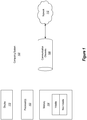
Figure 1 illustrates an example computing system in which the principles described herein may be employed; -
Figure 2 illustrates a flowchart of a method for supporting an organization mode in which multiple user interface elements may be organized within a user interface; -
Figure 3 illustrates a user interface in which there are multiple user interface elements positioned to fit a conceptual grid pattern; -
Figure 4 illustrates a user interface that is similar to the user interface ofFigure 3 , except now six unoccupied grid positions are illustrated; -
Figure 5 illustrates a user interface that is similar to the user interface ofFigure 4 , except that now the user is moving a user interface element; -
Figure 6 illustrates a user interface that is similar to the user interface ofFigure 5 , except that rather than the user interface element being dropped to the unoccupied grid positions highlighted inFigure 5 , the user interface element snaps to a position adjacent the existing user interface elements in the start board; -
Figure 7 illustrates another flowchart of a method for supporting an organization mode in which user interface elements may be organized within a user interface; -
Figure 8 illustrates a user interface in organization mode and in which a selected user interface element is in a different position and has a similar contextual actions menu; -
Figure 9 illustrates a user interface in organization mode and in which a different type of user interface element has a similar contextual actions menu; and -
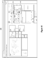
Figure 10 illustrates a user interface in organization mode in which a user interface is illustrated, and which includes a contextual actions menu is illustrated. - At least some embodiments described herein provide for the supporting of an organization mode in a user interface that displays multiple user interface elements.
- From the prior art document
US2009/0132942 A1 a graphical user interface is described for organizing the simultaneous display of information from a multitude of information sources, into a grid of tiles, each tile can refresh its content independently of the others. - From the prior art document
US2009/0319939 A1 a two-dimensional canvas onto which heterogenic objects of various types may be arranged side-by-side is known. Each type of object can be selected and can be moved by drag and drop operation. - In accordance with a first aspect described herein, the multiple user interface elements fit over a grid positions that are at least conceptually imposed over a canvas. Each of the user interface elements occupies one or more of the grid positions and has boundaries corresponding to boundaries between grid positions. The system detects that the user interface is to enter an organization mode in which one or more of the user interface elements may be organized on the user interface. For instance, the user might make an explicit gesture recognized by the system as a user intent to enter organization mode. In response, the grid positions are displayed on the canvas. This allows the user to more easily see, during organization mode, where user interface elements may be placed. This is especially useful when the user interfaces may take on a predetermined number of combinations of shapes and sizes, each combination fittable over one or more grid positions. In some embodiments, as the user moves and/or resizes a user interface element, one or more corresponding grid positions are highlighted to show where the user interface element would be placed if the move or resize operation were to conclude at that moment.
- In accordance with a second aspect described herein, while in organization mode, a contextual actions menu is caused to appear with respect to a particular user interface element. The contextual actions menu includes multiple organization mode commands, including one or more that may be directed selected from the contextual actions menu to invoke the command. For instance, perhaps those organization mode commands that are more frequently performed in organization mode (such as pin or unpin) might be directly invoked from the contextual actions menu, while other less frequently invoked organization mode commands may be reachable from the contextual actions menu, but not directly invoked.
- Some introductory discussion of a computing system will be described with respect to
Figure 1 . Then, example user interfaces, methods and supporting architectures will be described with respect to subsequent figures. - Computing systems are now increasingly taking a wide variety of forms. Computing systems may, for example, be handheld devices, appliances, laptop computers, desktop computers, mainframes, distributed computing systems, or even devices that have not conventionally been considered a computing system. In this description and in the claims, the term "computing system" is defined broadly as including any device or system (or combination thereof) that includes at least one physical and tangible processor, and a physical and tangible memory capable of having thereon computer-executable instructions that may be executed by the processor. The memory may take any form and may depend on the nature and form of the computing system. A computing system may be distributed over a network environment and may include multiple constituent computing systems.
- As illustrated in
Figure 1 , in its most basic configuration, acomputing system 100 typically includes at least oneprocessing unit 102 andmemory 104. Thememory 104 may be physical system memory, which may be volatile, non-volatile, or some combination of the two. The term "memory" may also be used herein to refer to non-volatile mass storage such as physical storage media. If the computing system is distributed, the processing, memory and/or storage capability may be distributed as well. As used herein, the term "executable module" or "executable component" can refer to software objects, routines, or methods that may be executed on the computing system. The different components, modules, engines, and services described herein may be implemented as objects or processes that execute on the computing system (e.g., as separate threads). - In the description that follows, embodiments are described with reference to acts that are performed by one or more computing systems. If such acts are implemented in software, one or more processors of the associated computing system that performs the act direct the operation of the computing system in response to having executed computer-executable instructions. For example, such computer-executable instructions may be embodied on one or more computer-readable media that form a computer program product. An example of such an operation involves the manipulation of data. The computer-executable instructions (and the manipulated data) may be stored in the
memory 104 of thecomputing system 100.Computing system 100 may also containcommunication channels 108 that allow thecomputing system 100 to communicate with other message processors over, for example,network 110. Thecomputing system 100 also includes adisplay 112 for displaying user interfaces such as those described herein. - Embodiments described herein may comprise or utilize a special purpose or general-purpose computer including computer hardware, such as, for example, one or more processors and system memory, as discussed in greater detail below. Embodiments described herein also include physical and other computer-readable media for carrying or storing computer-executable instructions and/or data structures. Such computer-readable media can be any available media that can be accessed by a general purpose or special purpose computer system. Computer-readable media that store computer-executable instructions are physical storage media. Computer-readable media that carry computer-executable instructions are transmission media. Thus, by way of example, and not limitation, embodiments of the invention can comprise at least two distinctly different kinds of computer-readable media: computer storage media and transmission media.
- Computer storage media includes RAM, ROM, EEPROM, CD-ROM or other optical disk storage, magnetic disk storage or other magnetic storage devices, or any other tangible medium which can be used to store desired program code means in the form of computer-executable instructions or data structures and which can be accessed by a general purpose or special purpose computer.
- A "network" is defined as one or more data links that enable the transport of electronic data between computer systems and/or modules and/or other electronic devices. When information is transferred or provided over a network or another communications connection (either hardwired, wireless, or a combination of hardwired or wireless) to a computer, the computer properly views the connection as a transmission medium. Transmissions media can include a network and/or data links which can be used to carry or desired program code means in the form of computer-executable instructions or data structures and which can be accessed by a general purpose or special purpose computer. Combinations of the above should also be included within the scope of computer-readable media.
- Further, upon reaching various computer system components, program code means in the form of computer-executable instructions or data structures can be transferred automatically from transmission media to computer storage media (or vice versa). For example, computer-executable instructions or data structures received over a network or data link can be buffered in RAM within a network interface module (e.g., a "NIC"), and then eventually transferred to computer system RAM and/or to less volatile computer storage media at a computer system. Thus, it should be understood that computer storage media can be included in computer system components that also (or even primarily) utilize transmission media.
- Computer-executable instructions comprise, for example, instructions and data which, when executed at a processor, cause a general purpose computer, special purpose computer, or special purpose processing device to perform a certain function or group of functions. The computer executable instructions may be, for example, binaries, intermediate format instructions such as assembly language, or even source code. Although the subject matter has been described in language specific to structural features and/or methodological acts, it is to be understood that the subject matter defined in the appended claims is not necessarily limited to the described features or acts described above. Rather, the described features and acts are disclosed as example forms of implementing the claims.
- Those skilled in the art will appreciate that the invention may be practiced in network computing environments with many types of computer system configurations, including, personal computers, desktop computers, laptop computers, message processors, hand-held devices, multi-processor systems, microprocessor-based or programmable consumer electronics, network PCs, minicomputers, mainframe computers, mobile telephones, PDAs, pagers, routers, switches, and the like. The invention may also be practiced in distributed system environments where local and remote computer systems, which are linked (either by hardwired data links, wireless data links, or by a combination of hardwired and wireless data links) through a network, both perform tasks. In a distributed system environment, program modules may be located in both local and remote memory storage devices.
-
Figure 2 illustrates a flowchart of amethod 200 for supporting an organization mode in which multiple user interface elements may be organized within a user interface. The user interface elements are displayed on the user interface (act 201). In some embodiments, the multiple user interface elements are displayed so as to conform to a grid pattern. The grid pattern may be conceptual in that it may not be always displayed. The grid pattern has multiple grid positions on a canvas. For instance, the grid positions may each be rectangular or square. Each user interface element is fitted to the one or more grid positions in that the user interface element occupies the one or more grid positions and has boundaries corresponding to the boundaries of the one or more grid positions. For instance, each of the user interface elements has one of a set of predetermined combinations of shape and size, each combination allowing the user interface element to fit over one or more grid positions. - For instance,
Figure 3 illustrates a user interface in which there are tenuser interface elements 311 through 320 positioned in astart board 310. Theuser interface elements user interface elements user interface elements user interface element 319 is four grid units wide by two grid units high. Thegrid unit 311 is six grid units wide by four grid units high. When each of the predetermined combination of shape and size may fit well over a grid pattern, the various user interface elements may be fitted well over the grid pattern, with the boundary between user interface elements corresponding to boundaries between grid positions. In the illustrated embodiments, each of theuser interface elements 311 through 320 are rectangular and being some positive integer multiple (1, 2, 3 and so forth) of a grid unit wide, and some positive integer multiple (1, 2, 3 and so forth) of a grid unit high. - The
user interface 300 also shows auser interface element 330 that is outside of thestart board 310. In one embodiment, theuser interface 300 shows a portion of an extensible canvas that is extendible in an extendable dimension (e.g., horizontally. As new user interface elements are added to the canvas by selection of a current user interface element in the canvas, the canvas may extend in an extendable direction (e.g., rightward) in the extensible dimension. Accordingly, theuser interface element 330 might be caused to appear when the user selects one of the user interface elements inFigure 3 . - Referring back to
Figure 2 , while the user interface elements are still being displayed (in act 201), the computing system (e.g., thecomputing system 100 ofFigure 1 ) detects a user instruction (act 202) representing an intent to organize one or more of the user interface elements on the canvas. For instance, the computing system may detect an instruction to enter an organization mode for the user interface. In the organization mode, the user interface elements may be organized (e.g., moved, resized, copied, or the like) on the canvas in a manner not permitted outside of organization mode. - In response to this user instruction, the user interface shows at least some of the grid positions to be displayed (act 203). For instance,
Figure 4 illustrates auser interface 400 that is similar to theuser interface 300 ofFigure 3 , except now sixunoccupied grid positions 401 through 406 are illustrated (and the previously labelled elements ofFigure 3 are not labelled inFigure 3 to avoid congested labels). ComparingFigure 4 to Figure 3 , the grid positions were not displayed before entering organization mode. In some embodiments, the display of the grid positions may be delayed until the user actually performs some organization (e.g., moving, resizing and/or copying) of one or more user interface elements. For instance, the grid positions may be displayed when the user begins moving or resizing a user interface element. To further emphasize that theuse interface 400 is in organization mode, theuser interface 400 may be darkened as compared to theuser interface 300, although this darkening is not illustrated inFigure 4 . -
Figure 5 illustrates auser interface 500 that is similar to theuser interface 400 ofFigure 4 , except that now the user is moving theuser interface element 316. Here, two changes have happened in response. First, additional unoccupied grid positions are illustrated due to a) the availability of the previous four grid positions where theuser interface element 316 originated from, and b) the availability of additional unoccupied grid positions in the direction (rightward) that theuser interface element 316 has been moved. Second, the unoccupied grid positions are highlighted (as represented by diagonal lined fill and solid line boundaries) to represents where theuser interface element 316 would be placed on theuser interface element 316 were to be dropped. As previously mentioned, in organization mode, the user interface elements may be darkened to emphasize that the user interface elements are blocked from performing their normal operations. Instead, they can just be organized. However, when a user interface element is being organized, perhaps there is also some visualization assigned to that user interface element also, to emphasize that it is the subject of organization. For instance, perhapsuser interface element 316 is no longer darkened, thus giving visual attention to theuser interface element 316 being organized. - The analysis of which of the unoccupied grid positions should be highlighted may be repeatedly performed as the move operation continues, thus giving the user a real-time impression of the effect of dropping the user interface element at any given point in time. In this example, only the
user interface element 316 is being moved, but the principles may also apply if multiple user interface elements are moved in a group. - In
Figure 5 , the highlighted grid positions are underneath theuser interface element 316 being moved. However, there may be times when the highlighted grid positions are not underneath theuser interface element 316 being moved. For instance, to keep the start board in condensed fashion with user interface elements being close together, the computing system may snap theuser interface element 316 to be adjacent the other user interface elements in the start board that are not being moved. For instance,Figure 6 illustrates auser interface 600 that is similar to the user interfaced 500 ofFigure 5 , except that rather than theuser interface element 316 being dropped to the unoccupied grid positions highlighted inFigure 5 , theuser interface element 316 snaps to a position adjacent the existing user interface elements in the start board. The user interface element may also be moved to be a constituent part of other user interface elements, such as theuser interface element 330 ofFigure 3 . - The visualized unoccupied grid positions may also be helpful when resizing one or the user interface elements. When resizing, the unoccupied user interface elements that would be occupied by the resized user interface element may also be highlighted. The analysis of which of the unoccupied grid positions should be highlighted may be repeatedly performed as the resize operation continues, thus giving the user a real-time impression of the effect of resizing of the user interface element at any given point in time.
-
Figure 7 illustrates another flowchart of amethod 700 for supporting an organization mode in which user interface elements may be organized within a user interface. Again, the system displays multiple user interface elements on a user interface (act 701). In this broader embodiment, there is no requirement that the user interface elements have particular shapes and sizes, althoughFigures 6 and8 through 10 will illustrates examples in which the user interface elements do have predetermined combinations of shape and size that fit into the same grid pattern. - Again, the user interface enters organization mode (act 702) in the user interface and while displaying the user interface elements.
Figure 6 again illustrates an example of the user interface elements in organization mode. The organization mode may be entered at the instruction of the user and/or upon the occurrence of one or more other events. - A contextual actions menu is then caused to appear with respect to a particular user interface element (act 703). For instance, referring to
Figure 6 , suppose that the user interface element 601 is the particular user interface element which has itscontextual actions menu 610 caused to appear. The contextual actions menu of an element may be caused to appear for a particular user interface element in response to a user instructions to display the contextual actions menu (such as the selection of the user interface element while in organization mode) and/or in response to one or more other events. In one embodiment, the contextual actions menu that is caused to appear with respect to a particular user interface element when the user interface is in organization mode, is different that the contextual actions menu that would appear with respect to the particular user interface element when the user interface is not in organization mode. For instance, the available commands may be at least partially different in organization mode as compared to a mode (e.g., a normal mode) that is not in the organization mode. - The
contextual actions menu 610 is illustrated as having three organization mode commands. Two of the organization commands may be directly selected from the contextual actions menu. For instance, the user might directly select thepin command 611 to pin the user interface element to a portion of the user interface (such as the start board 310). The user might also directly select theunpin command 612 to unpin the user interface element from a portion of the user interface. Direct commands may be disabled depending on the circumstances. For instance, thepin command 611 may be disabled and not visualized if theuser interface element 610 is already pinned to the start board. Likewise, theunpin command 612 may be disabled and not visualized if the user interface element 620 is not pinned to the start board. - The commands that may be directly invoked from the
context menu 610 may, for instance, be the commands that are more commonly used. For instance, the system may cause the commands that are more commonly used in general to be displayed. On the other hand, the system may more proactively monitor the usage of a given user, and provide direct commands on the context menu for those commands that are more commonly performed in organization mode by the given user. For instance, if a given user performs resizing to a particular size more often, a resize control may be added to the contextual actions menu for direct selection. -
Figure 8 illustrates auser interface 800 in organization mode and in which auser interface element 801 is in a different user interface element that is maximized to occupy much of the current view of the display. This emphasizes that the context menu behavior may be the same regardless of the context of the user navigation. -
Figure 9 illustrates auser interface 900 in organization mode and in which a different type ofuser interface element 901 has a similarcontextual actions menu 910. This emphasizes that the contextual actions menu behavior may be consistent across different kinds of user interface elements. -
Figure 10 illustrates auser interface 1000 in organization mode in which auser interface 1001 is illustrated, and which includes acontextual actions menu 1010 is illustrated. The user has selected theother control 1013 thereby showing that could not be directly executed from thecontextual actions menu 1010. Instead, the indirect contextual actions menu commands are executed from the drop downmenu 1020. In this example, the user may select the pin command, the remove part command (which deletes the user interface element), the clone command (which copies an instance of the user interface element), a hero wide command (which resizes the user interface element to a predetermined size), and a done customizing command (which selects the user interface element). - Accordingly, the principles described herein provide support for organization mode of operation in systems that display multiple user interface elements that are to be organized.
- The described embodiments are to be considered in all respects only as illustrative and not restrictive. The scope of the invention is, therefore, indicated by the appended claims rather than by the foregoing description.
Claims (8)
- A computer-implemented method performed by one or more processors of a computing system which includes a memory containing computer-executable instructions which, when executed by the one or more processors, cause the one or more processors to perform the computer-implemented method, which permits visualizing an organization mode in which a plurality of user interface elements may be organized within a user interface, the computer-implemented method comprising:displaying a plurality of user interface elements on a user interface, (201)wherein the interface elements conform to a grid pattern having a plurality of grid positions on a canvas, each individual interface element occupying one or more of the grid positions and having boundaries corresponding to the boundaries of the one or more grid positions occupied by the individual interface element;the one or more processors detecting at the interface an input representing an intent to organize one or more of the interface elements on the canvas (202); andin response to detecting said input representing an intent to organize one or more of the interface elements on the canvas, the one or more processors initiating an organization mode at the interface, wherein unoccupied grid positions of the canvas are displayed (203) to permit visualization of where interface elements can be moved, added, enlarged or reduced in size, in order to facilitate visualizing organization of one or more interface elements on the interface,characterised by detecting the input comprises detecting an instruction to move one or more interface elements on the canvas, andfor each instance of detected movement of an individual interface element, the one or more processors highlighting the one or more of the grid positions occupied by the individual interface element, wherein the highlighted grid positions represent a location on the canvas where the moved individual interface element would be placed if the moved individual interface element were to be dropped on the canvas.
- The computer-implemented method in accordance with Claim 1, wherein detecting the input comprises detecting a user gesture that signals the intent to organize one or more interface elements relative to the interface.
- The computer-implemented method in accordance with Claim 1, wherein the highlighted one or more grid positions are defined as having been underneath the moved individual interface element.
- The computer-implemented method in accordance with Claim 1, wherein the highlighted one or more grid positions are defined as being adjacent another of the interface elements on the canvas, and not underneath the moved individual interface element.
- The computer-implemented method in accordance with Claim 1, further comprising:the one or more processors detecting resizing of a selected interface element on the canvas; andthe one or more processors highlighting the one or more of the grid positions occupied by the selected interface element, wherein the highlighted grid positions represent a location on the canvas where the selected resized interface element would be placed if the selected resized interface element were to be dropped on the canvas.
- The computer-implemented method in accordance with Claim 1, further comprising activating a contextual actions menu with respect to a selected interface element, wherein the contextual actions menu comprises a plurality of organization mode commands that are selectable relative to the selected interface element.
- The computer-implemented method in accordance with Claim 1, wherein the computer-executable instructions for the computer-implemented method are provided on a computer program product comprised of one or more storage devices from which the computer-executable instructions can be uploaded to the computer system memory.
- A computer interface system which permits visualizing an organization mode in which a plurality of user interface elements may be organized within a user interface, comprising:one or more processors (102);a display (112);a memory (104) containing computer-executable instructions which, when executed by the one or more processors perform a computer-implemented method which permits visualizing an organization mode in which a plurality of user interface elements may be organized within a user interface, the computer-implemented method comprising:displaying a plurality of user interface elements on a user interface (201), wherein the interface elements conform to a grid pattern having a plurality of grid positions on a canvas, each individual interface element occupying one or more of the grid positions and having boundaries corresponding to the boundaries of the one or more grid positions occupied by the individual interface element;the one or more processors detecting at the interface an input representing an intent to organize one or more of the interface elements on the canvas (203); andin response to detecting said input representing an intent to organize one or more of the interface elements on the canvas, the one or more processors initiating an organization mode at the interface, wherein unoccupied grid positions of the canvas are displayed (203) to permit visualization of where interface elements can be moved, added, enlarged or reduced in size, in order to facilitate visualizing organization of one or more interface elements on the interface,characterised by detecting the input comprises detecting an instruction to move one or more interface elements on the canvas, andfor each instance of detected movement of an individual interface element, the one or more processors are configured for highlighting the one or more of the grid positions occupied by the individual interface element, wherein the highlighted grid positions represent a location on the canvas where the moved individual interface element would be placed if the moved individual interface element were to be dropped on the canvas.
Applications Claiming Priority (3)
| Application Number | Priority Date | Filing Date | Title |
|---|---|---|---|
| US201461974191P | 2014-04-02 | 2014-04-02 | |
| US14/310,617 US10078411B2 (en) | 2014-04-02 | 2014-06-20 | Organization mode support mechanisms |
| PCT/US2015/023448 WO2015153526A1 (en) | 2014-04-02 | 2015-03-31 | Organizing user interface elements |
Publications (2)
| Publication Number | Publication Date |
|---|---|
| EP3126946A1 EP3126946A1 (en) | 2017-02-08 |
| EP3126946B1 true EP3126946B1 (en) | 2019-06-19 |
Family
ID=54209752
Family Applications (1)
| Application Number | Title | Priority Date | Filing Date |
|---|---|---|---|
| EP15716338.7A Active EP3126946B1 (en) | 2014-04-02 | 2015-03-31 | Organizing user interface elements |
Country Status (5)
| Country | Link |
|---|---|
| US (2) | US10078411B2 (en) |
| EP (1) | EP3126946B1 (en) |
| KR (1) | KR102265126B1 (en) |
| CN (1) | CN106164836A (en) |
| WO (1) | WO2015153526A1 (en) |
Families Citing this family (10)
| Publication number | Priority date | Publication date | Assignee | Title |
|---|---|---|---|---|
| US8826174B2 (en) | 2008-06-27 | 2014-09-02 | Microsoft Corporation | Using visual landmarks to organize diagrams |
| USD769303S1 (en) * | 2015-01-20 | 2016-10-18 | Microsoft Corporation | Display screen with animated graphical user interface |
| USD769305S1 (en) * | 2015-01-20 | 2016-10-18 | Microsoft Corporation | Display screen with animated graphical user interface |
| USD840425S1 (en) * | 2017-05-03 | 2019-02-12 | Google Llc | Display screen with transitional graphical user interface |
| USD858564S1 (en) * | 2017-05-05 | 2019-09-03 | Brainlab Ag | Display screen with an animated graphical user interface for medical software |
| USD851674S1 (en) * | 2017-11-17 | 2019-06-18 | Outbrain Inc. | Electronic device display or portion thereof with animated graphical user interface |
| US10936343B2 (en) * | 2018-04-18 | 2021-03-02 | Microsoft Technology Licensing, Llc | In-context event orchestration of physical and cyber resources |
| KR102819235B1 (en) * | 2019-11-11 | 2025-06-11 | 삼성전자주식회사 | Display apparatus and the control method thereof |
| CN114442973A (en) * | 2020-11-04 | 2022-05-06 | 南方电网电动汽车服务有限公司 | Screen display method, device, computer equipment and storage medium |
| CN115373644A (en) * | 2022-09-16 | 2022-11-22 | 武汉虹信技术服务有限责任公司 | Visual UI (user interface) generation method and system |
Family Cites Families (92)
| Publication number | Priority date | Publication date | Assignee | Title |
|---|---|---|---|---|
| US5490241A (en) | 1989-10-06 | 1996-02-06 | Xerox Corporation | Interactive computer graphics system for making precise drawings |
| US5123087A (en) | 1990-04-27 | 1992-06-16 | Ashlar, Inc. | Geometric inference engine |
| US5226117A (en) * | 1990-05-15 | 1993-07-06 | International Business Machines Corporation | Method for simultaneous update and change in parent and child windows |
| US5204947A (en) * | 1990-10-31 | 1993-04-20 | International Business Machines Corporation | Application independent (open) hypermedia enablement services |
| EP0672277B1 (en) | 1992-12-01 | 1998-05-13 | Microsoft Corporation | A method and system for in-place interaction with embedded objects |
| JPH0721241A (en) | 1993-06-24 | 1995-01-24 | Meidensha Corp | Continuous copying method for graphic |
| US5471578A (en) | 1993-12-30 | 1995-11-28 | Xerox Corporation | Apparatus and method for altering enclosure selections in a gesture based input system |
| EP0661620B1 (en) | 1993-12-30 | 2001-03-21 | Xerox Corporation | Apparatus and method for executing multiple concatenated command gestures in a gesture based input system |
| DE69428675T2 (en) | 1993-12-30 | 2002-05-08 | Xerox Corp | Apparatus and method for supporting an implicit structuring of free-form lists, overviews, texts, tables and diagrams in an input system and editing system based on hand signals |
| US5555357A (en) | 1994-06-03 | 1996-09-10 | Claris Corporation | Computer system and method for generating and manipulating charts and diagrams |
| US5588108A (en) | 1994-09-27 | 1996-12-24 | Micrografx, Inc. | System and method for generating graphics charts |
| JP3118379B2 (en) | 1994-09-28 | 2000-12-18 | 三洋電機株式会社 | Layout processing device |
| US5694563A (en) | 1994-12-13 | 1997-12-02 | Microsoft Corporation | Method and system for transferring data to common destinations using a common destination list |
| JPH08221500A (en) | 1995-02-15 | 1996-08-30 | Dainippon Printing Co Ltd | Primitive moving method and form design system |
| US5565888A (en) | 1995-02-17 | 1996-10-15 | International Business Machines Corporation | Method and apparatus for improving visibility and selectability of icons |
| US5644737A (en) | 1995-06-06 | 1997-07-01 | Microsoft Corporation | Method and system for stacking toolbars in a computer display |
| US5892554A (en) | 1995-11-28 | 1999-04-06 | Princeton Video Image, Inc. | System and method for inserting static and dynamic images into a live video broadcast |
| US6493006B1 (en) | 1996-05-10 | 2002-12-10 | Apple Computer, Inc. | Graphical user interface having contextual menus |
| US5861886A (en) | 1996-06-26 | 1999-01-19 | Xerox Corporation | Method and apparatus for grouping graphic objects on a computer based system having a graphical user interface |
| US5886694A (en) | 1997-07-14 | 1999-03-23 | Microsoft Corporation | Method for automatically laying out controls in a dialog window |
| US6437804B1 (en) | 1997-10-23 | 2002-08-20 | Aprisma Management Technologies, Inc | Method for automatic partitioning of node-weighted, edge-constrained graphs |
| US6034684A (en) | 1997-11-24 | 2000-03-07 | Sony Corporation | Identification of data items on a screen display using landmark and grid line graphical objects |
| US6065021A (en) | 1998-04-07 | 2000-05-16 | Adobe Systems Incorporated | Apparatus and method for alignment of graphical elements in electronic document |
| US6323879B1 (en) | 1998-05-14 | 2001-11-27 | Autodesk, Inc. | Method and system for determining the spacing of objects |
| US6154220A (en) | 1998-10-19 | 2000-11-28 | Microsoft Corporation | Rectilinear layout |
| DE69811127T2 (en) | 1998-11-30 | 2003-11-20 | Actcon Control Ab, Hisings Backa | METHOD TO ENTER OBJECTS IN THE WORK AREA IN A COMPUTER APPLICATION |
| US6426761B1 (en) | 1999-04-23 | 2002-07-30 | Internation Business Machines Corporation | Information presentation system for a graphical user interface |
| US6636648B2 (en) | 1999-07-02 | 2003-10-21 | Eastman Kodak Company | Albuming method with automatic page layout |
| US7322524B2 (en) | 2000-10-20 | 2008-01-29 | Silverbrook Research Pty Ltd | Graphic design software using an interface surface |
| US7987431B2 (en) * | 1999-10-29 | 2011-07-26 | Surfcast, Inc. | System and method for simultaneous display of multiple information sources |
| US6425121B1 (en) | 2000-01-14 | 2002-07-23 | Softwire Technology, Llp | Method and apparatus for resolving divergent paths in graphical programming environments |
| AU2001242320A1 (en) | 2000-03-30 | 2001-10-15 | Ideogramic Aps | Method for gesture based modeling |
| US6907580B2 (en) | 2000-12-14 | 2005-06-14 | Microsoft Corporation | Selection paradigm for displayed user interface |
| US7103527B2 (en) | 2000-12-20 | 2006-09-05 | Microsoft Corporation | Negotiated interconnection of visual modeling elements |
| US7320120B2 (en) | 2000-12-20 | 2008-01-15 | Microsoft Corporation | Pluggable notations and semantics for visual modeling elements |
| US7689917B2 (en) | 2000-12-20 | 2010-03-30 | National Instruments Corporation | Automatically generating a sub-graphical program in response to user input configuring a graphical program node |
| JP2002208021A (en) | 2001-01-10 | 2002-07-26 | Brother Ind Ltd | Image editing device |
| US7058653B2 (en) | 2001-09-17 | 2006-06-06 | Ricoh Company, Ltd. | Tree system diagram output method, computer program and recording medium |
| US7299424B2 (en) | 2002-05-14 | 2007-11-20 | Microsoft Corporation | Lasso select |
| US7039898B2 (en) | 2002-07-12 | 2006-05-02 | Netspective Communications, Llc | Computer system for performing reusable software application development from a set of declarative executable specifications |
| US7356774B2 (en) | 2002-08-13 | 2008-04-08 | National Instruments Corporation | Grouping components of a measurement system |
| US8225224B1 (en) | 2003-02-25 | 2012-07-17 | Microsoft Corporation | Computer desktop use via scaling of displayed objects with shifts to the periphery |
| US7962522B2 (en) * | 2003-06-03 | 2011-06-14 | Norris Iii Forbes Holten | Flexible, dynamic menu-based web-page architecture |
| US7310780B2 (en) | 2003-08-14 | 2007-12-18 | International Business Machines Corporation | Methods, systems and computer program products for visually tethering related graphical objects |
| US8131739B2 (en) | 2003-08-21 | 2012-03-06 | Microsoft Corporation | Systems and methods for interfacing application programs with an item-based storage platform |
| US7529811B2 (en) | 2003-08-21 | 2009-05-05 | Microsoft Corporation | Systems and methods for the implementation of a core schema for providing a top-level structure for organizing units of information manageable by a hardware/software interface system |
| US7318199B2 (en) | 2003-09-11 | 2008-01-08 | Oracle International Corporation | Algorithm for automatic layout of objects in a database |
| US20050102634A1 (en) | 2003-11-10 | 2005-05-12 | Sloo David H. | Understandable navigation of an information array |
| US8276095B2 (en) * | 2004-02-20 | 2012-09-25 | Advanced Intellectual Property Group, Llc | System for and method of generating and navigating within a workspace of a computer application |
| US7460134B2 (en) | 2004-03-02 | 2008-12-02 | Microsoft Corporation | System and method for moving computer displayable content into a preferred user interactive focus area |
| JP2007536634A (en) | 2004-05-04 | 2007-12-13 | フィッシャー−ローズマウント・システムズ・インコーポレーテッド | Service-oriented architecture for process control systems |
| US8312382B2 (en) | 2004-05-11 | 2012-11-13 | Sap Ag | Developing and executing applications with configurable patterns |
| US20050273761A1 (en) | 2004-06-07 | 2005-12-08 | The Mathworks, Inc. | Freehand system and method for creating, editing, and manipulating block diagrams |
| US7342583B2 (en) | 2004-11-17 | 2008-03-11 | Pics, Inc. | Automated system and method to develop computer-administered research questionnaires using a virtual questionnaire model |
| JP4238222B2 (en) | 2005-01-04 | 2009-03-18 | インターナショナル・ビジネス・マシーンズ・コーポレーション | Object editing system, object editing method, and object editing program |
| JP4106058B2 (en) * | 2005-01-04 | 2008-06-25 | インターナショナル・ビジネス・マシーンズ・コーポレーション | Information processing apparatus, frame rearrangement method, and program for rearranging frames in window |
| US7814427B2 (en) | 2005-01-05 | 2010-10-12 | Microsoft Corporation | Object model tree diagram |
| WO2006136958A2 (en) | 2005-01-25 | 2006-12-28 | Dspv, Ltd. | System and method of improving the legibility and applicability of document pictures using form based image enhancement |
| US7253823B2 (en) | 2005-03-15 | 2007-08-07 | Microsoft Corporation | System and method for providing 1D and 2D connectors in a connected diagram |
| US7483028B2 (en) | 2005-03-15 | 2009-01-27 | Microsoft Corporation | Providing 1D and 2D connectors in a connected diagram |
| US7444597B2 (en) | 2005-03-18 | 2008-10-28 | Microsoft Corporation | Organizing elements on a web page via drag and drop operations |
| US7340686B2 (en) * | 2005-03-22 | 2008-03-04 | Microsoft Corporation | Operating system program launch menu search |
| US7474310B2 (en) | 2005-08-12 | 2009-01-06 | Microsoft Corporation | Object association in a computer generated drawing environment |
| US8365135B2 (en) | 2005-10-27 | 2013-01-29 | International Business Machines Corporation | Computer method and apparatus for connection creation in a software modeling system |
| US8607147B2 (en) | 2005-12-09 | 2013-12-10 | International Business Machines Corporation | System and methods for previewing alternative compositions and arrangements when composing a strictly-structured flow diagram |
| US8140987B2 (en) | 2005-12-29 | 2012-03-20 | Sap Ag | GUI modeling of web services |
| US20080036771A1 (en) | 2006-02-21 | 2008-02-14 | Seok-Hyung Bae | Pen-based drawing system |
| US7477263B2 (en) | 2006-03-10 | 2009-01-13 | International Business Machines Corporation | Relayout of all or part of a graph in association with a change in state of a graph element |
| US20070266307A1 (en) | 2006-05-15 | 2007-11-15 | Microsoft Corporation Microsoft Patent Group | Auto-layout of shapes |
| US20080022215A1 (en) | 2006-07-21 | 2008-01-24 | Robert Lee | Apparatus, system, and method for expanding and collapsing a list in a diagram environment |
| US7657840B2 (en) | 2006-11-02 | 2010-02-02 | International Business Machines Corporation | System and method for providing a navigable grid to allow for accessible drag-drop in visual modeling tools |
| US8965787B2 (en) | 2007-12-17 | 2015-02-24 | Smooth Productions Inc. | Communications system and method for serving electronic content |
| US20110161827A1 (en) | 2008-03-05 | 2011-06-30 | Anastasia Dedis | Social media communication and contact organization |
| US20090228786A1 (en) | 2008-03-10 | 2009-09-10 | Microsoft Corporation | Flexible creation of auto-layout compliant diagrams |
| US8156445B2 (en) | 2008-06-20 | 2012-04-10 | Microsoft Corporation | Controlled interaction with heterogeneous data |
| US8826174B2 (en) | 2008-06-27 | 2014-09-02 | Microsoft Corporation | Using visual landmarks to organize diagrams |
| US20100153313A1 (en) * | 2008-12-15 | 2010-06-17 | Symbol Technologies, Inc. | Interface adaptation system |
| US9213466B2 (en) * | 2009-07-20 | 2015-12-15 | Apple Inc. | Displaying recently used functions in context sensitive menu |
| US8438500B2 (en) | 2009-09-25 | 2013-05-07 | Apple Inc. | Device, method, and graphical user interface for manipulation of user interface objects with activation regions |
| CN102109944A (en) * | 2009-12-23 | 2011-06-29 | 联想(北京)有限公司 | Window management method, device thereof and computer |
| US8209630B2 (en) | 2010-01-26 | 2012-06-26 | Apple Inc. | Device, method, and graphical user interface for resizing user interface content |
| JP5573487B2 (en) * | 2010-08-20 | 2014-08-20 | ソニー株式会社 | Information processing apparatus, program, and operation control method |
| US9728164B2 (en) * | 2011-05-31 | 2017-08-08 | Lenovo (Singapore) Pte. Ltd. | Moving a tile across multiple workspaces |
| US20130019175A1 (en) | 2011-07-14 | 2013-01-17 | Microsoft Corporation | Submenus for context based menu system |
| US20130067412A1 (en) * | 2011-09-09 | 2013-03-14 | Microsoft Corporation | Grouping selectable tiles |
| US10254909B2 (en) * | 2011-10-03 | 2019-04-09 | Disney Enterprises, Inc. | System and method for providing a user interface for media navigation by attribute compass |
| KR101819513B1 (en) * | 2012-01-20 | 2018-01-17 | 엘지전자 주식회사 | Mobile terminal and method for controlling the same |
| EP2820608A1 (en) * | 2012-02-28 | 2015-01-07 | Bohemian Wrappsody AB | Methods, systems, devices and arrangements for providing gifts |
| US10503373B2 (en) | 2012-03-14 | 2019-12-10 | Sony Interactive Entertainment LLC | Visual feedback for highlight-driven gesture user interfaces |
| WO2013157013A1 (en) | 2012-04-17 | 2013-10-24 | Hewlett - Packard Development Company, L.P. | Selection of user interface elements of a graphical user interface |
| US9043722B1 (en) * | 2012-06-19 | 2015-05-26 | Surfwax, Inc. | User interfaces for displaying relationships between cells in a grid |
| CN103135891B (en) * | 2013-02-06 | 2016-09-14 | 天脉聚源(北京)传媒科技有限公司 | A kind of method and device of user interface process |
-
2014
- 2014-06-20 US US14/310,617 patent/US10078411B2/en active Active
-
2015
- 2015-03-31 KR KR1020167027095A patent/KR102265126B1/en not_active Expired - Fee Related
- 2015-03-31 CN CN201580018505.3A patent/CN106164836A/en active Pending
- 2015-03-31 WO PCT/US2015/023448 patent/WO2015153526A1/en not_active Ceased
- 2015-03-31 EP EP15716338.7A patent/EP3126946B1/en active Active
-
2018
- 2018-08-30 US US16/117,351 patent/US10627980B2/en active Active
Non-Patent Citations (1)
| Title |
|---|
| None * |
Also Published As
| Publication number | Publication date |
|---|---|
| US20180373397A1 (en) | 2018-12-27 |
| WO2015153526A1 (en) | 2015-10-08 |
| US10627980B2 (en) | 2020-04-21 |
| KR20160138437A (en) | 2016-12-05 |
| US10078411B2 (en) | 2018-09-18 |
| US20150286343A1 (en) | 2015-10-08 |
| EP3126946A1 (en) | 2017-02-08 |
| KR102265126B1 (en) | 2021-06-14 |
| CN106164836A (en) | 2016-11-23 |
Similar Documents
| Publication | Publication Date | Title |
|---|---|---|
| US10627980B2 (en) | Organization mode support mechanisms | |
| JP6138641B2 (en) | MAP INFORMATION DISPLAY DEVICE, MAP INFORMATION DISPLAY METHOD, AND MAP INFORMATION DISPLAY PROGRAM | |
| RU2540826C2 (en) | Internal scroll activation and cursor adornment | |
| KR102549529B1 (en) | Method for launching a second application using a first application icon in an electronic device | |
| KR101867651B1 (en) | Arranging tiles | |
| US9372612B2 (en) | Exposing inertial snap points | |
| EP2606416B1 (en) | Highlighting of objects on a display | |
| EP2738661A2 (en) | Method for displaying applications and electronic device thereof | |
| US20120174020A1 (en) | Indication of active window when switching tasks in a multi-monitor environment | |
| HK1222731A1 (en) | Pan and selection gesture detection | |
| US10222970B2 (en) | Selecting and performing contextual actions via user interface objects | |
| US10133454B2 (en) | Stackable pagination indicators | |
| US20130067394A1 (en) | Pointer invocable navigational user interface | |
| CN105378633A (en) | Visual selection and grouping | |
| EP3840346A1 (en) | Control operating method and electronic apparatus | |
| US20150324068A1 (en) | User interface structure (uis) for geographic information system applications | |
| JPH06202776A (en) | Method and system for display of pressure on input device | |
| JP2018508088A (en) | Graphic user interface prototype production method and apparatus | |
| KR102095039B1 (en) | Apparatus and method for receiving touch input in an apparatus providing a touch interface | |
| JP5988450B2 (en) | Method for displaying nodes, computer for displaying nodes, and computer program therefor | |
| US20200081584A1 (en) | Computing device display management | |
| KR20150019064A (en) | Method of displaying classfied information and device of displaying classfied information using the same | |
| JP2000089886A (en) | Desk top management system/method using virtual polyhedron | |
| EP2754040B1 (en) | Visualization and editing of composite layouts | |
| JP5762257B2 (en) | Plant monitoring and control device |
Legal Events
| Date | Code | Title | Description |
|---|---|---|---|
| STAA | Information on the status of an ep patent application or granted ep patent |
Free format text: STATUS: THE INTERNATIONAL PUBLICATION HAS BEEN MADE |
|
| PUAI | Public reference made under article 153(3) epc to a published international application that has entered the european phase |
Free format text: ORIGINAL CODE: 0009012 |
|
| STAA | Information on the status of an ep patent application or granted ep patent |
Free format text: STATUS: REQUEST FOR EXAMINATION WAS MADE |
|
| 17P | Request for examination filed |
Effective date: 20160930 |
|
| AK | Designated contracting states |
Kind code of ref document: A1 Designated state(s): AL AT BE BG CH CY CZ DE DK EE ES FI FR GB GR HR HU IE IS IT LI LT LU LV MC MK MT NL NO PL PT RO RS SE SI SK SM TR |
|
| AX | Request for extension of the european patent |
Extension state: BA ME |
|
| DAV | Request for validation of the european patent (deleted) | ||
| DAX | Request for extension of the european patent (deleted) | ||
| RIC1 | Information provided on ipc code assigned before grant |
Ipc: G06F 3/0481 20130101AFI20181213BHEP Ipc: G06F 3/0486 20130101ALI20181213BHEP Ipc: G06F 3/0484 20130101ALI20181213BHEP |
|
| GRAP | Despatch of communication of intention to grant a patent |
Free format text: ORIGINAL CODE: EPIDOSNIGR1 |
|
| STAA | Information on the status of an ep patent application or granted ep patent |
Free format text: STATUS: GRANT OF PATENT IS INTENDED |
|
| INTG | Intention to grant announced |
Effective date: 20190118 |
|
| GRAS | Grant fee paid |
Free format text: ORIGINAL CODE: EPIDOSNIGR3 |
|
| GRAA | (expected) grant |
Free format text: ORIGINAL CODE: 0009210 |
|
| STAA | Information on the status of an ep patent application or granted ep patent |
Free format text: STATUS: THE PATENT HAS BEEN GRANTED |
|
| AK | Designated contracting states |
Kind code of ref document: B1 Designated state(s): AL AT BE BG CH CY CZ DE DK EE ES FI FR GB GR HR HU IE IS IT LI LT LU LV MC MK MT NL NO PL PT RO RS SE SI SK SM TR |
|
| REG | Reference to a national code |
Ref country code: GB Ref legal event code: FG4D |
|
| REG | Reference to a national code |
Ref country code: CH Ref legal event code: EP |
|
| REG | Reference to a national code |
Ref country code: IE Ref legal event code: FG4D |
|
| REG | Reference to a national code |
Ref country code: DE Ref legal event code: R096 Ref document number: 602015032240 Country of ref document: DE |
|
| REG | Reference to a national code |
Ref country code: AT Ref legal event code: REF Ref document number: 1146334 Country of ref document: AT Kind code of ref document: T Effective date: 20190715 |
|
| REG | Reference to a national code |
Ref country code: NL Ref legal event code: FP |
|
| PG25 | Lapsed in a contracting state [announced via postgrant information from national office to epo] |
Ref country code: FI Free format text: LAPSE BECAUSE OF FAILURE TO SUBMIT A TRANSLATION OF THE DESCRIPTION OR TO PAY THE FEE WITHIN THE PRESCRIBED TIME-LIMIT Effective date: 20190619 Ref country code: NO Free format text: LAPSE BECAUSE OF FAILURE TO SUBMIT A TRANSLATION OF THE DESCRIPTION OR TO PAY THE FEE WITHIN THE PRESCRIBED TIME-LIMIT Effective date: 20190919 Ref country code: LT Free format text: LAPSE BECAUSE OF FAILURE TO SUBMIT A TRANSLATION OF THE DESCRIPTION OR TO PAY THE FEE WITHIN THE PRESCRIBED TIME-LIMIT Effective date: 20190619 Ref country code: AL Free format text: LAPSE BECAUSE OF FAILURE TO SUBMIT A TRANSLATION OF THE DESCRIPTION OR TO PAY THE FEE WITHIN THE PRESCRIBED TIME-LIMIT Effective date: 20190619 Ref country code: HR Free format text: LAPSE BECAUSE OF FAILURE TO SUBMIT A TRANSLATION OF THE DESCRIPTION OR TO PAY THE FEE WITHIN THE PRESCRIBED TIME-LIMIT Effective date: 20190619 Ref country code: SE Free format text: LAPSE BECAUSE OF FAILURE TO SUBMIT A TRANSLATION OF THE DESCRIPTION OR TO PAY THE FEE WITHIN THE PRESCRIBED TIME-LIMIT Effective date: 20190619 |
|
| REG | Reference to a national code |
Ref country code: LT Ref legal event code: MG4D |
|
| PG25 | Lapsed in a contracting state [announced via postgrant information from national office to epo] |
Ref country code: GR Free format text: LAPSE BECAUSE OF FAILURE TO SUBMIT A TRANSLATION OF THE DESCRIPTION OR TO PAY THE FEE WITHIN THE PRESCRIBED TIME-LIMIT Effective date: 20190920 Ref country code: LV Free format text: LAPSE BECAUSE OF FAILURE TO SUBMIT A TRANSLATION OF THE DESCRIPTION OR TO PAY THE FEE WITHIN THE PRESCRIBED TIME-LIMIT Effective date: 20190619 Ref country code: BG Free format text: LAPSE BECAUSE OF FAILURE TO SUBMIT A TRANSLATION OF THE DESCRIPTION OR TO PAY THE FEE WITHIN THE PRESCRIBED TIME-LIMIT Effective date: 20190919 Ref country code: RS Free format text: LAPSE BECAUSE OF FAILURE TO SUBMIT A TRANSLATION OF THE DESCRIPTION OR TO PAY THE FEE WITHIN THE PRESCRIBED TIME-LIMIT Effective date: 20190619 |
|
| REG | Reference to a national code |
Ref country code: AT Ref legal event code: MK05 Ref document number: 1146334 Country of ref document: AT Kind code of ref document: T Effective date: 20190619 |
|
| PG25 | Lapsed in a contracting state [announced via postgrant information from national office to epo] |
Ref country code: SK Free format text: LAPSE BECAUSE OF FAILURE TO SUBMIT A TRANSLATION OF THE DESCRIPTION OR TO PAY THE FEE WITHIN THE PRESCRIBED TIME-LIMIT Effective date: 20190619 Ref country code: EE Free format text: LAPSE BECAUSE OF FAILURE TO SUBMIT A TRANSLATION OF THE DESCRIPTION OR TO PAY THE FEE WITHIN THE PRESCRIBED TIME-LIMIT Effective date: 20190619 Ref country code: RO Free format text: LAPSE BECAUSE OF FAILURE TO SUBMIT A TRANSLATION OF THE DESCRIPTION OR TO PAY THE FEE WITHIN THE PRESCRIBED TIME-LIMIT Effective date: 20190619 Ref country code: CZ Free format text: LAPSE BECAUSE OF FAILURE TO SUBMIT A TRANSLATION OF THE DESCRIPTION OR TO PAY THE FEE WITHIN THE PRESCRIBED TIME-LIMIT Effective date: 20190619 Ref country code: AT Free format text: LAPSE BECAUSE OF FAILURE TO SUBMIT A TRANSLATION OF THE DESCRIPTION OR TO PAY THE FEE WITHIN THE PRESCRIBED TIME-LIMIT Effective date: 20190619 Ref country code: PT Free format text: LAPSE BECAUSE OF FAILURE TO SUBMIT A TRANSLATION OF THE DESCRIPTION OR TO PAY THE FEE WITHIN THE PRESCRIBED TIME-LIMIT Effective date: 20191021 |
|
| PG25 | Lapsed in a contracting state [announced via postgrant information from national office to epo] |
Ref country code: IT Free format text: LAPSE BECAUSE OF FAILURE TO SUBMIT A TRANSLATION OF THE DESCRIPTION OR TO PAY THE FEE WITHIN THE PRESCRIBED TIME-LIMIT Effective date: 20190619 Ref country code: IS Free format text: LAPSE BECAUSE OF FAILURE TO SUBMIT A TRANSLATION OF THE DESCRIPTION OR TO PAY THE FEE WITHIN THE PRESCRIBED TIME-LIMIT Effective date: 20191019 Ref country code: SM Free format text: LAPSE BECAUSE OF FAILURE TO SUBMIT A TRANSLATION OF THE DESCRIPTION OR TO PAY THE FEE WITHIN THE PRESCRIBED TIME-LIMIT Effective date: 20190619 Ref country code: ES Free format text: LAPSE BECAUSE OF FAILURE TO SUBMIT A TRANSLATION OF THE DESCRIPTION OR TO PAY THE FEE WITHIN THE PRESCRIBED TIME-LIMIT Effective date: 20190619 |
|
| PG25 | Lapsed in a contracting state [announced via postgrant information from national office to epo] |
Ref country code: TR Free format text: LAPSE BECAUSE OF FAILURE TO SUBMIT A TRANSLATION OF THE DESCRIPTION OR TO PAY THE FEE WITHIN THE PRESCRIBED TIME-LIMIT Effective date: 20190619 |
|
| PG25 | Lapsed in a contracting state [announced via postgrant information from national office to epo] |
Ref country code: DK Free format text: LAPSE BECAUSE OF FAILURE TO SUBMIT A TRANSLATION OF THE DESCRIPTION OR TO PAY THE FEE WITHIN THE PRESCRIBED TIME-LIMIT Effective date: 20190619 Ref country code: PL Free format text: LAPSE BECAUSE OF FAILURE TO SUBMIT A TRANSLATION OF THE DESCRIPTION OR TO PAY THE FEE WITHIN THE PRESCRIBED TIME-LIMIT Effective date: 20190619 |
|
| PG25 | Lapsed in a contracting state [announced via postgrant information from national office to epo] |
Ref country code: IS Free format text: LAPSE BECAUSE OF FAILURE TO SUBMIT A TRANSLATION OF THE DESCRIPTION OR TO PAY THE FEE WITHIN THE PRESCRIBED TIME-LIMIT Effective date: 20200224 |
|
| REG | Reference to a national code |
Ref country code: DE Ref legal event code: R097 Ref document number: 602015032240 Country of ref document: DE |
|
| PLBE | No opposition filed within time limit |
Free format text: ORIGINAL CODE: 0009261 |
|
| STAA | Information on the status of an ep patent application or granted ep patent |
Free format text: STATUS: NO OPPOSITION FILED WITHIN TIME LIMIT |
|
| PG2D | Information on lapse in contracting state deleted |
Ref country code: IS |
|
| 26N | No opposition filed |
Effective date: 20200603 |
|
| PG25 | Lapsed in a contracting state [announced via postgrant information from national office to epo] |
Ref country code: SI Free format text: LAPSE BECAUSE OF FAILURE TO SUBMIT A TRANSLATION OF THE DESCRIPTION OR TO PAY THE FEE WITHIN THE PRESCRIBED TIME-LIMIT Effective date: 20190619 |
|
| PG25 | Lapsed in a contracting state [announced via postgrant information from national office to epo] |
Ref country code: MC Free format text: LAPSE BECAUSE OF FAILURE TO SUBMIT A TRANSLATION OF THE DESCRIPTION OR TO PAY THE FEE WITHIN THE PRESCRIBED TIME-LIMIT Effective date: 20190619 |
|
| REG | Reference to a national code |
Ref country code: CH Ref legal event code: PL |
|
| REG | Reference to a national code |
Ref country code: BE Ref legal event code: MM Effective date: 20200331 |
|
| PG25 | Lapsed in a contracting state [announced via postgrant information from national office to epo] |
Ref country code: LU Free format text: LAPSE BECAUSE OF NON-PAYMENT OF DUE FEES Effective date: 20200331 |
|
| PG25 | Lapsed in a contracting state [announced via postgrant information from national office to epo] |
Ref country code: IE Free format text: LAPSE BECAUSE OF NON-PAYMENT OF DUE FEES Effective date: 20200331 Ref country code: LI Free format text: LAPSE BECAUSE OF NON-PAYMENT OF DUE FEES Effective date: 20200331 Ref country code: CH Free format text: LAPSE BECAUSE OF NON-PAYMENT OF DUE FEES Effective date: 20200331 |
|
| PG25 | Lapsed in a contracting state [announced via postgrant information from national office to epo] |
Ref country code: BE Free format text: LAPSE BECAUSE OF NON-PAYMENT OF DUE FEES Effective date: 20200331 |
|
| PG25 | Lapsed in a contracting state [announced via postgrant information from national office to epo] |
Ref country code: MT Free format text: LAPSE BECAUSE OF FAILURE TO SUBMIT A TRANSLATION OF THE DESCRIPTION OR TO PAY THE FEE WITHIN THE PRESCRIBED TIME-LIMIT Effective date: 20190619 Ref country code: CY Free format text: LAPSE BECAUSE OF FAILURE TO SUBMIT A TRANSLATION OF THE DESCRIPTION OR TO PAY THE FEE WITHIN THE PRESCRIBED TIME-LIMIT Effective date: 20190619 |
|
| PG25 | Lapsed in a contracting state [announced via postgrant information from national office to epo] |
Ref country code: MK Free format text: LAPSE BECAUSE OF FAILURE TO SUBMIT A TRANSLATION OF THE DESCRIPTION OR TO PAY THE FEE WITHIN THE PRESCRIBED TIME-LIMIT Effective date: 20190619 |
|
| P01 | Opt-out of the competence of the unified patent court (upc) registered |
Effective date: 20230505 |
|
| PGFP | Annual fee paid to national office [announced via postgrant information from national office to epo] |
Ref country code: NL Payment date: 20240220 Year of fee payment: 10 |
|
| PGFP | Annual fee paid to national office [announced via postgrant information from national office to epo] |
Ref country code: FR Payment date: 20240221 Year of fee payment: 10 |
|
| PGFP | Annual fee paid to national office [announced via postgrant information from national office to epo] |
Ref country code: DE Payment date: 20250218 Year of fee payment: 11 |
|
| PGFP | Annual fee paid to national office [announced via postgrant information from national office to epo] |
Ref country code: GB Payment date: 20250221 Year of fee payment: 11 |
|
| REG | Reference to a national code |
Ref country code: NL Ref legal event code: MM Effective date: 20250401 |
|
| PG25 | Lapsed in a contracting state [announced via postgrant information from national office to epo] |
Ref country code: NL Free format text: LAPSE BECAUSE OF NON-PAYMENT OF DUE FEES Effective date: 20250401 |
|
| PG25 | Lapsed in a contracting state [announced via postgrant information from national office to epo] |
Ref country code: FR Free format text: LAPSE BECAUSE OF NON-PAYMENT OF DUE FEES Effective date: 20250331 |