EP3126264B1 - Verfahren und vorrichtung für farbausgabe - Google Patents
Verfahren und vorrichtung für farbausgabe Download PDFInfo
- Publication number
- EP3126264B1 EP3126264B1 EP15716356.9A EP15716356A EP3126264B1 EP 3126264 B1 EP3126264 B1 EP 3126264B1 EP 15716356 A EP15716356 A EP 15716356A EP 3126264 B1 EP3126264 B1 EP 3126264B1
- Authority
- EP
- European Patent Office
- Prior art keywords
- adaptor
- valve body
- bore
- paint
- container
- Prior art date
- Legal status (The legal status is an assumption and is not a legal conclusion. Google has not performed a legal analysis and makes no representation as to the accuracy of the status listed.)
- Active
Links
Images






Classifications
-
- B—PERFORMING OPERATIONS; TRANSPORTING
- B65—CONVEYING; PACKING; STORING; HANDLING THIN OR FILAMENTARY MATERIAL
- B65D—CONTAINERS FOR STORAGE OR TRANSPORT OF ARTICLES OR MATERIALS, e.g. BAGS, BARRELS, BOTTLES, BOXES, CANS, CARTONS, CRATES, DRUMS, JARS, TANKS, HOPPERS, FORWARDING CONTAINERS; ACCESSORIES, CLOSURES, OR FITTINGS THEREFOR; PACKAGING ELEMENTS; PACKAGES
- B65D83/00—Containers or packages with special means for dispensing contents
- B65D83/14—Containers for dispensing liquid or semi-liquid contents by internal gaseous pressure, i.e. aerosol containers comprising propellant
- B65D83/16—Actuating means
- B65D83/164—Actuators comprising a manually operated valve and being attachable to the aerosol container, e.g. downstream a valve fitted to the container; Actuators associated to container valves with valve seats located outside the aerosol container
-
- B—PERFORMING OPERATIONS; TRANSPORTING
- B65—CONVEYING; PACKING; STORING; HANDLING THIN OR FILAMENTARY MATERIAL
- B65D—CONTAINERS FOR STORAGE OR TRANSPORT OF ARTICLES OR MATERIALS, e.g. BAGS, BARRELS, BOTTLES, BOXES, CANS, CARTONS, CRATES, DRUMS, JARS, TANKS, HOPPERS, FORWARDING CONTAINERS; ACCESSORIES, CLOSURES, OR FITTINGS THEREFOR; PACKAGING ELEMENTS; PACKAGES
- B65D83/00—Containers or packages with special means for dispensing contents
- B65D83/14—Containers for dispensing liquid or semi-liquid contents by internal gaseous pressure, i.e. aerosol containers comprising propellant
- B65D83/16—Actuating means
- B65D83/18—Hand lever actuators
- B65D83/182—Hand lever actuators combined with hand grips
- B65D83/184—Hand lever actuators combined with hand grips at the end of extension rods
-
- B—PERFORMING OPERATIONS; TRANSPORTING
- B65—CONVEYING; PACKING; STORING; HANDLING THIN OR FILAMENTARY MATERIAL
- B65D—CONTAINERS FOR STORAGE OR TRANSPORT OF ARTICLES OR MATERIALS, e.g. BAGS, BARRELS, BOTTLES, BOXES, CANS, CARTONS, CRATES, DRUMS, JARS, TANKS, HOPPERS, FORWARDING CONTAINERS; ACCESSORIES, CLOSURES, OR FITTINGS THEREFOR; PACKAGING ELEMENTS; PACKAGES
- B65D83/00—Containers or packages with special means for dispensing contents
- B65D83/14—Containers for dispensing liquid or semi-liquid contents by internal gaseous pressure, i.e. aerosol containers comprising propellant
- B65D83/38—Details of the container body
- B65D83/382—Details of the container body the container body or a closure attached to the container body must be punctured before first use
-
- B—PERFORMING OPERATIONS; TRANSPORTING
- B05—SPRAYING OR ATOMISING IN GENERAL; APPLYING FLUENT MATERIALS TO SURFACES, IN GENERAL
- B05C—APPARATUS FOR APPLYING FLUENT MATERIALS TO SURFACES, IN GENERAL
- B05C17/00—Hand tools or apparatus using hand held tools, for applying liquids or other fluent materials to, for spreading applied liquids or other fluent materials on, or for partially removing applied liquids or other fluent materials from, surfaces
- B05C17/005—Hand tools or apparatus using hand held tools, for applying liquids or other fluent materials to, for spreading applied liquids or other fluent materials on, or for partially removing applied liquids or other fluent materials from, surfaces for discharging material from a reservoir or container located in or on the hand tool through an outlet orifice by pressure without using surface contacting members like pads or brushes
- B05C17/00589—Hand tools or apparatus using hand held tools, for applying liquids or other fluent materials to, for spreading applied liquids or other fluent materials on, or for partially removing applied liquids or other fluent materials from, surfaces for discharging material from a reservoir or container located in or on the hand tool through an outlet orifice by pressure without using surface contacting members like pads or brushes comprising a guiding rotating element, e.g. a wheel
-
- B—PERFORMING OPERATIONS; TRANSPORTING
- B65—CONVEYING; PACKING; STORING; HANDLING THIN OR FILAMENTARY MATERIAL
- B65D—CONTAINERS FOR STORAGE OR TRANSPORT OF ARTICLES OR MATERIALS, e.g. BAGS, BARRELS, BOTTLES, BOXES, CANS, CARTONS, CRATES, DRUMS, JARS, TANKS, HOPPERS, FORWARDING CONTAINERS; ACCESSORIES, CLOSURES, OR FITTINGS THEREFOR; PACKAGING ELEMENTS; PACKAGES
- B65D83/00—Containers or packages with special means for dispensing contents
- B65D83/14—Containers for dispensing liquid or semi-liquid contents by internal gaseous pressure, i.e. aerosol containers comprising propellant
- B65D83/70—Pressure relief devices
Definitions
- This invention generally relates to methods and apparatuses for dispensing paint from pressurized paint containers.
- the paint can may explode if one tries to burn or crush it.
- the applied heat or the crushing action will increase the paint can's internal pressure and thus an explosion risk is presented.
- the paint remaining in a paint can may represent a hazardous chemical or fire hazard and thus another disposal problem.
- US 2,887,272 A describes a device for mixing pressurized fluid treating agent with a carrier fluid.
- WO 2006/018593 A2 discloses a dispensing device for the addition of products to seal and semi sealed systems such as for example water treatment chemicals to domestic closed loop systems.
- US 2008/169047 A1 is related to a handheld, low-flow dispenser comprises an enclosure holding a gas cartridge.
- US 2011/180626 A1 describes a foldable extension pipe which consists of upper and lower pipe sections which are folded and unfolded.
- US 3,880,187 A discloses a safety relief valve comprising a plug inserted into an aperture in the bottom of a pressure container.
- US 2011/180626 A1 and US 3880187 A both fail to disclose an adaptor and piercing means for a sealed container.
- a fluid dispensing apparatus may be used in dispensing a paint fluid from an associated paint container under a pressure greater than ambient.
- the associated paint container may contain associated paint and may have a pierceable membrane.
- the fluid dispensing apparatus may comprise: a valve body having a top, a bottom and a bore that extends through the valve body; an adaptor having a top, a bottom, a bore that extends through the adaptor and a piercing member; and, a nozzle attached to the top of the valve body and having a bore that is communicatable with the valve body bore.
- the bottom of the valve body may be attached to the top of the adaptor and the adaptor bore may communicate with the valve body bore.
- the fluid dispensing apparatus may be operable by attaching the bottom of the adaptor to the associated paint container to pierce the pierceable membrane with the piercing member to communicate the associated paint within the paint container with the adaptor bore and thus with the valve body bore.
- the nozzle may be operable to permit the associated paint within the associated paint container to flow under the pressure out of the associated paint container, through the adaptor bore, through the valve body bore and through the nozzle bore to ambient.
- a method of dispensing a paint fluid from an associated paint container under a pressure greater than ambient may be provided.
- the associated paint container may contain associated paint and may have a pierceable membrane.
- the method may comprise the steps of: (A) providing a fluid dispensing apparatus comprising: (1) a valve body having a top, a bottom and a bore that extends through the valve body; (2) an adaptor having a top attached to the bottom of the valve body, a bottom, a bore that extends through the adaptor and a piercing member; wherein the adaptor bore communicates with the valve body bore; and, (3) a nozzle attached to the top of the valve body and having a bore that is communicatable with the valve body bore; (B) attaching the bottom of the adaptor to the associated paint container to pierce the pierceable membrane with the piercing member to communicate the associated paint within the paint container with the adaptor bore and thus with the valve body bore; and, (C) operating the nozzle to permit the associated
- a paint apparatus may comprise: (A) a paint container containing a paint fluid under a pressure greater than ambient and having a pierceable membrane; (B) a fluid dispensing apparatus comprising: (1) a valve body having a top, a bottom and a bore that extends through the valve body; (2) an adaptor having a top, a bottom, a bore that extends through the adaptor and a piercing member, wherein the bottom of the valve body is attached to the top of the adaptor and the adaptor bore communicates with the valve body bore; and, (3) a nozzle attached to the top of the valve body and having a bore that is communicatable with the valve body bore.
- the fluid dispensing apparatus may be operable by attaching the bottom of the adaptor to the paint container to pierce the pierceable membrane with the piercing member to communicate the paint within the paint container with the adaptor bore and thus with the valve body bore.
- the nozzle may be operable to permit the paint within the paint container to flow under the pressure out of the paint container, through the adaptor bore, through the valve body bore and through the nozzle bore to ambient.
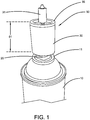
- FIGURE 1 shows a perspective view of a pressurized paint container 10 equipped with a fluid dispensing apparatus 50 according to some embodiments of this invention. While the pressurized paint container shown is a can, this invention will work with any type, size and shape of pressurized paint container chosen with the sound judgment of a person of skill in the art.
- the paint dispensed by the fluid dispensing apparatus 50 may be a pressurized paint fluid that is a liquid, gas, vapor, or a mixture thereof. While the fluid dispensing apparatus 50 is designed to dispense paint, it may have application to other fluids as well.
- the fluid dispensing apparatus 50 may, in some embodiments, include a nozzle 31, a valve body 30, and an adaptor 20.
- the nozzle 31 may be like nozzle 202 discussed above. Because the operation of such nozzles 31, 202 - laterally displaceable to permit the contents to exit the nozzle and biased into a non-displaced position where the contents cannot exit the nozzle - are well known to people of skill in the art, no details will be provided here.
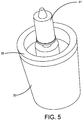
- the container cap 11 may, in one embodiment, be fixedly joined to the top of the pressurized container 10 such as being crimped in a known manner.
- the container cap 11 may be, in one embodiment, positioned substantially concentrically with the container's longitudinal axis.
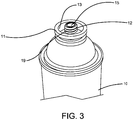
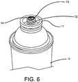
- the container cap 11 may have a well 13, a coupling element 12, and a fluid passage bore 14 (visible in FIGURE 6 ).
- a membrane 15 may cover the bore 14. Membrane 15 may be pierceable and located with respect to fluid passage bore 14 in such a manner as to seal bore 14 and prevent fluid from exiting container 10 until it is pierced.
- FIGURE 6 shows membrane 15 in a pierced condition which exposes fluid passage bore 14 to outside of the pressurized container 10.
- the membrane 15 may be fixedly attached to the coupling element 12.
- Coupling element 12 may be of any size, shape and relative position chosen with the sound judgment of a person of skill in the art.
- coupling element 12 may have a threaded section 19, as shown.
- the coupling element 12 is cylindrical in shape and the threaded section 19 is on the exterior surface of the coupling element 12.
- Materials used to form container cap 11 may be chosen with the sound judgment of a person of skill in the art.
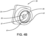
- Adaptor 20 may be, in some embodiments, a generally cylindrically shaped component with a top and an opposing bottom. Referring to FIGURE 4B , located on the bottom of adaptor 20 may be a coupling element 21. Coupling element 21 may engage with coupling element 12 of container cap 11. In one specific embodiment, shown, coupling element 21 may be formed on an inner cylindrical shaped portion of adaptor 20 and may have a threaded section 57. The adaptor 20 may have a fluid passage bore 26 that may extend from the top to the bottom of the adaptor 20.
- the adaptor 20 may also have a piercing member 27 used to pierce membrane 15 (shown unpierced in FIGURE 3 and pierced in FIGURE 6 ).
- the piercing member in some embodiments, may be located concentric to the longitudinal axis of fluid passage bore 26 and may extend beyond bottom surface of fluid passage bore 26.
- the piercing member may be positioned at least partially within the adaptor bore 26.
- On the end of piercing member 27 that extends beyond the bottom surface of bore 26, a tip may be formed and configured to pierce membrane 15.
- the adaptor 20 may also have a seal 23 that prevents fluid flow except through the bore 26.
- the seal 23 may be formed of an elastomeric material.
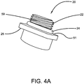
- a coupling element 22 located on the top of the adaptor 20 may be a coupling element 22.
- coupling element 22 may be formed on an outer cylindrical shaped portion of adaptor 20 and may have a threaded section 59.
- the coupling element 22 may be used to engage with a coupling element of the valve body 30, as will be discussed further below.
- a seal 24 may be used to seal the connection between the top of the adaptor 20 and the bottom of the valve body 30.
- the seal 24 is an O-ring received around the cylindrically shaped portion of the adaptor 20 that has the coupling element 22.
- the seal 24 may be formed of an elastomeric material.
- the adaptor 20 may have a shoulder 25 extending outwardly, as shown.
- the top of the shoulder 25 may have a surface 51 that acts as a stop that contacts a surface of the valve body 30 when the adaptor 20 and valve body 30 are attached together.
- the adaptor 20 may be formed of any material(s) chosen with the sound judgment of a person of skill in the art. In one embodiment, the adaptor 20 is formed of copper.
- the valve body 30 may have a valve cap 35 on its top, as shown.
- the valve cap 35 may have any design suitable to properly receive the nozzle 31 as chosen by a person of skill in the art.
- the valve cap 35 is similar in design to the top of the can 200, just below the nozzle 202, shown in FIGURE 2 .
- the valve body 30 may be substantially cylindrical in shape and may have a height 61. The height 61 may range between 1.0 to 4.0 inches.
- Valve body 30 may have a fluid passage bore 34, as shown in FIGURE 10 .
- the bore 34 may extend from bottom to the top of the valve body 30, as shown.
- the bore 34 may be centered along the valve body's longitudinal axis.
- a coupling element 33 may be located on a bottom surface, as shown.
- coupling element 33 may be formed on an inner cylindrical shaped portion of valve body 30 and may have a threaded section 37.
- the coupling element 33 may be used to engage with coupling element 22 of the adaptor 20.
- threaded section 37 engages threaded section 59 to attach the valve body 30 to the adaptor 20.
- the valve body 30 may be formed of any material chosen with the sound judgment of a person of skill in the art.
- the nozzle 31, which may have a fluid passage bore 32, may be joined to the valve cap 35 in a known manner - similar to how the nozzle 202 is joined to can 200 in FIGURE 2 .
- Nozzle 31 may dispense paint out of the valve body 30 to the ambient when the nozzle 31 is operated in a known manner (similar to nozzle 202 in FIGURE 2 ).
- nozzle 31 may be configured such that it can be selectively deflected from its longitudinal axis and when so deflected its bore 32 is in fluid communication with central bore 34.
- Nozzle 31 may be configured such that it is capable of being deflected by manually generated forces.
- Nozzle 31 may also be configured with a biased position such that when no force is applied, nozzle 31 returns to a position that prevents fluid communication with central bore 34.
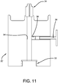
- FIGURE 11 illustrates another embodiment valve body 30'.
- Valve body 30' is similar to valve body 30 described above except that it may include a pressure relief valve 36.
- valve body 30' may include a transverse fluid passage bore 38. Bore 38 may communicate on one end with bore 34 and on the opposing end with the area outside of the confines of valve body 30'. Located in bore 38 may be pressure relief valve 36.
- Pressure relief valve 36 may be chosen to operate in a plurality of modes. One mode may be such that in an initial condition relief valve 36 substantially seals bore 38 from the area outside. A second mode may be, once the user depresses relief valve 36, transverse bore 38 connects central bore 34 with the area outside of the confines of valve body 30'.
- a third mode is the relief valve 36 opens automatically when pressure inside the paint container 10 exceeds a predetermined value. When this occurs, the pressure inside container 10 is minimized or released to ambient.
- Materials used in forming pressure relief valve 36 may be chosen with the sound judgment of a person of skill in the art.
- the operation modes of pressure relief valve 36 may also be chosen with the sound judgment of a person of skill in the art.
- valve body 30 has a valve cap 35 and attaches to a nozzle 31 as with previously described valve bodies 30 and 30'.
- Valve body 30 is designed to resemble the size and shape of the container. Compare FIGURE 14 with FIGURE 2 .
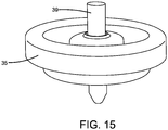
- FIGURE 15 shows stem 39 which extends through the valve cap 35 and is used to operate nozzle 31 in a known manner.
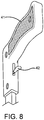
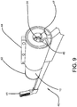
- a dispensing wand 40 may be used. On one end of dispensing wand 40 may be positioned a grip 41 configured to allow a user to easily hold wand 40. Also on grip end of wand 40 may be trigger 42, seen best in FIGURE 8 . The opposing end of wand 40 may contain a wheel 43 which may be rotationally attached to wand 40 in such a manner as to allow wand 40 to easily be moved along a surface by a user as the wheel 43 rolls along the surface. Also on opposing end of wand 40 may be a receiving portion 44 of such a size and shape to securely retain container 10 to the wand 40.
- the receiving portion 44 can be of any type chosen with the sound judgment of a person of skill in the art, for the embodiment shown the receiving portion 44 includes an opening 47, see FIGURE 9 , into which the pressurized container 10 may be inserted.
- Located within receiving portion 44 may be a nozzle lever 45.
- a nozzle lever 45 may be operatively connected to trigger 42. This connection may be such that a user may manually apply a force to trigger 42, thus displacing trigger 42, and this displacement results in nozzle lever 45 also being displaced.
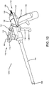
- Each spray apparatus 100A, 100B may include a housing 102, a barrel 104 supported to the housing 102 and a handle 106 also supported to the housing 102.
- the spray apparatuses 100A, 100B may have a pistol-shape but other shapes may work well also.
- the barrel 104 may be hollow and may extend distally (away from the handle) to a tip 108.
- the hollow barrel 104 and tip 108 may define a fluid passageway bore.
- the tip 108 is the distal end of the apparatus 100A, 100B and the point from which paint fluid is dispensed.
- the tip 108 comprises a fitting to which another component (not shown) may be attached and from which the paint fluid is dispensed.
- the barrel 104 may decrease in outside diameter, as shown in FIGURE 12 , in the distal direction.
- a container receiving portion 110 may be supported to the housing 102 and sized and shaped to securely retain/support a paint container 10 or 200.
- the container receiving portion 110 may include an outer, generally circular ring 112 defining an opening 114, and a nozzle reception connector 116.
- the user may attach the pressurized container 10, 200 to the apparatus 100A, 100B, as shown in FIGURE 13 , such that the nozzle 31, 202 is received within the nozzle reception connector 116 and the valve body 30 or top of can 200 is received within the opening 114.
- the nozzle reception connector 116 communicates with the fluid passageway in the barrel 104 so that the fluid paint within the pressurized container 10, 200 can be dispensed out the tip 108, when desired.
- the container receiving portion 110 is positioned on a top portion of the apparatus 100A, 100B. As a result, gravity assists in assuring that all the liquid within the container is used.
- the receiving portion 110 may extend from the apparatus at an angle A1, as shown in FIGURE 13 , with respect to the longitudinal axis of the housing 102 and/or barrel 104.
- Angle A1 may be, in one embodiment, between 0 degrees and 90 degrees. In another embodiment, angle A1 may be between 10 degrees and 80 degrees. In yet another embodiment, angle A1 may be between 20 degrees and 70 degrees. For the embodiment shown, angle A1 is approximately 75 degrees.
- the spray apparatus 100A, 100B may also include a trigger 118 which is moveable relative to the housing 102 in order to deflect the nozzle 31, 202 to dispense the paint fluid.
- the trigger 118 may have a first end with a user contact surface 120 and a second end with a discharge contact surface 122.
- the trigger 118 is manually operated, in one embodiment moved, by the user, such as by squeezing the user contact surface 120 toward the handle 106 with the user's hand, the discharge contact surface 122 contacts the nozzle 31, 202 to deflect it and dispense the fluid.
- the trigger 118 may be moveably attached to the housing 102 in any manner chosen with the sound judgment of a person of skill in the art.
- the second end of the trigger 118 has a U-shaped portion with legs that extend juxtaposed to opposite sides of the housing 102 and pivots about pivot pin 124 which is received through the legs and through the housing 102.
- one pivot pin connects one leg to the housing on one side and a second pivot pin connects the other leg to the housing on the opposite side.
- an adjustment mechanism 132 may be used.
- the adjustment mechanism 132 may include bracket 126 that extends from the trigger 118 to a nut 128 that is threadingly received on a threaded rod 130 that is supported to and extending from the housing 102.
- the bracket 126 has an opening that receives the pivot pin 124.
- another bracket extends from the nut 128 to the trigger 118 on the other side of the apparatus 100A.
- the nut 128 can be rotated about rod 130 to move the bracket 126 and thus the trigger 118 along the longitudinal axis of the housing 102 (that is, along the longitudinal axis of the barrel 104) either closer to the receiving portion 110 or farther away.
- the user attaches the container 200 or container 10 equipped with the adaptor 20 and valve body 30, to the container receiving portion 110, as explained above. If necessary, the user adjusts the adjustment mechanism 132 to fit the container. The user then only has to position the tip 108 (or other component that is attached to the tip) to the desired location and then move the trigger 118 with respect to the handle 106 (such as by squeezing the trigger 118 toward the handle 106). The trigger 118 movement deflects the nozzle 31, 202 dispensing the fluid out of the container and out of the tip 108.
- spray apparatus 300 may include a housing 102, a barrel 104 supported to the housing 102, a handle 106 supported to the housing 102, and a trigger 118.
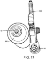
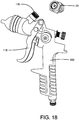
- FIGURE 16 shows the paint container 200 attached to the spray apparatus 300 and FIGURES 17 and 18 show the paint container 200 removed from the spray apparatus 300.
- FIGURE 17 shows the container's pieced membrane 15. Visible in each of these drawings is adaptor 20. In FIGURE 16 the adaptor 20 is positioned between the paint container 200 and the container receiving portion 110 of the spray apparatus 300.
- the paint container 10 may be equipped with container cap 11 by the manufacturer, in one embodiment.
- the fluid dispensing apparatus 50 may come to the user as a kit, in one embodiment, including the adaptor 20 and the valve body 30.
- the adaptor 20 may already be attached to the valve body 30.
- the coupling element 22 (see FIGURE 4A ) is attached to coupling element 33 (see FIGURE 10 ) to attach the adaptor 20 to the valve body 30.
- this may comprise rotating the adaptor 20 with respect to the valve body 30 with threaded section 59 engaged with threaded section 37 to "tighten” them together. This action may compress seal 24 and a lower service of the valve body 30 may contact surface 51, or come near to contacting it.
- the fluid dispensing apparatus 50 may come to the user already attached to the pressurized container 10.
- the user then attaches the fluid dispensing apparatus 50 to the paint container 10.
- this may comprise rotating the fluid dispensing apparatus 50 with respect to the paint container 10 with threaded section 57 engaged with threaded section 19 to "tighten” them together. This action may compress seal 23.
- piercing member 27 contacts and pierces membrane 15 (see FIGURE 3 to see the membrane 15 before it is pierced, and FIGURE 6 to see the membrane 15 after it is pierced).
- container bore 14 communicates with adaptor bore 26 which communicates with valve body bore 34.
- dispensing wand 40 may be used to dispense paint fluid from paint container 10 using the following method.
- the user may align the longitudinal axes of wand 40 with the dispensing apparatus 50.
- the user may insert container 10 and dispensing apparatus 50 into receiving portion 44, such as within opening 47, with nozzle 31 in proximity to nozzle lever 45.
- the user may then hold the wand 40 upright by grip 41 and place wheel 43 on desired surface to be traversed.
- the user may pull trigger 42 using his/her finger thus displacing trigger 42. This displacement may result in nozzle lever 45 also being displaced.
- nozzle lever 45 The displacement of nozzle lever 45 may then result in nozzle 31 being deflected and the contents of container 10 being dispensed.
- the user may then wheel wand 40 (that is, move the wand 40 using the wheel 43) and fluid dispensing apparatus 50 with container along a desired path thus easily dispensing paint fluid along the path.
- paint container 10 may be depressurized and substantially emptied of paint fluid according to the following method.
- the user may uncouple or detach container 10 from adaptor 20 (and thus from fluid dispensing apparatus 50) and separate the two components.
- container 10 separated from adaptor 20 With container 10 separated from adaptor 20, pierced membrane 15 is exposed to the ambient thus resulting in container 10 becoming depressurized.
- container 10 may be substantially emptied of fluid by placing it with pierced membrane 15 facing down and thus using gravity to force the paint fluid out of container 10. At this point paint container 10 may be easily deposed of.
- the fluid dispensing apparatus 50 may then be reused with another paint container.
- FIGURES 12 and 13 Methods of using the apparatuses shown in FIGURES 12 and 13 have been discussed above. It will be noted again, however, that the apparatuses of FIGURES 12 and 13 can be used either with a known paint container such as paint container 200 shown in FIGURE 2 or with a fluid dispensing apparatus 50 and paint container 10 according to various embodiments of this invention described above.
- a known paint container such as paint container 200 shown in FIGURE 2
- a fluid dispensing apparatus 50 and paint container 10 according to various embodiments of this invention described above.
Landscapes
- Chemical & Material Sciences (AREA)
- Dispersion Chemistry (AREA)
- Engineering & Computer Science (AREA)
- Mechanical Engineering (AREA)
- Containers And Packaging Bodies Having A Special Means To Remove Contents (AREA)
Claims (15)
- Fluidverteilvorrichtung (50) zur Verwendung bei der Verteilung eines Farbfluids aus einem zugehörigen Farbbehälter (10) unter einem Druck größer als die Umgebung, wobei der zugehörige Farbbehälter (10) zugehörige Farbe enthält und eine durchstoßbare Membran (15) aufweist, wobei die Fluidverteilvorrichtung (50) umfasst:einen Ventilkörper (30) mit einem oberen Ende, einem unteren Ende und einer Bohrung (34), die sich durch den Ventilkörper (30) erstreckt;einen Adapter (20) mit einem oberen Ende, einem unteren Ende, einer Bohrung (26), die sich durch den Adapter (20) erstreckt, und einem Durchstoßelement (27);eine Düse (31), die am oberen Ende des Ventilkörpers (30) angebracht ist und eine Bohrung (32) aufweist, die mit der Ventilkörperbohrung (34) in Verbindung gebracht werden kann;wobei das untere Ende des Ventilkörpers (30) an dem oberen Ende des Adapters (20) angebracht ist und die Adapterbohrung (26) mit der Ventilkörperbohrung (34) in Verbindung steht;wobei die Fluidverteilvorrichtung (50) durch Anbringen des unteren Endes des Adapters (20) an dem zugehörigen Farbbehälter (10) betreibbar ist, wobei die durchstoßbare Membran (15) mit dem Durchstoßelement (27) durchstochen wird, um die zugehörige Farbe innerhalb des Farbbehälters (10) mit der Adapterbohrung (26) und somit mit der Ventilkörperbohrung (34) in Verbindung zu bringen; und,wobei die Düse (31) betreibbar ist, um es der zugehörigen Farbe innerhalb des zugehörigen Farbbehälters (10) zu ermöglichen, unter dem Druck aus dem zugehörigen Farbbehälter (10) durch die Adapterbohrung (26), durch die Ventilkörperbohrung (34) und durch die Düsenbohrung (32) zur Umgebung zu fließen.
- Fluidverteilvorrichtung (50) nach Anspruch 1, wobei die Fluidverteilvorrichtung (50) durch Entfernen des unteren Endes des Adapters (20) aus dem zugehörigen Farbbehälter (10) betreibbar ist, um den Druck, größer als die Umgebung, aus dem zugehörigen Farbbehälter (10) zu entfernen, um zuzulassen, dass jegliche zugehörige Farbe innerhalb des zugehörigen Farbbehälters (10) bei Umgebungsdruck entfernt wird.
- Fluidverteilvorrichtung (50) nach Anspruch 1, wobei:das untere Ende des Ventilkörpers (30) ein Kupplungselement (33) umfasst;das obere Ende des Adapters (20) ein Kupplungselement (22) umfasst;das Kupplungselement (33) des Ventilkörpers (30) mit dem Kupplungselement (22) des Adapters (20) ineinandergreift, um den Ventilkörper (30) an dem Adapter (20) zu befestigen,und/oder wobei der Ventilkörper (30) ferner umfasst:einen Fluiddurchgang (38) mit einem ersten Ende, das mit der Ventilkörperbohrung (34) in Verbindung steht, und einem zweiten Ende, das mit einem Bereich außerhalb des Ventilkörpers (30) in Verbindung steht; und,ein Druckentlastungsventil (36), das zumindest teilweise innerhalb des Fluiddurchgangs (38) angeordnet ist und zwischen einer ersten Betriebsart, die den Fluiddurchgang (38) abdichtet, und einer zweiten Betriebsart betreibbar ist, die es ermöglicht, dass der Druck durch die Ventilkörperbohrung (34), durch den Fluiddurchgang (38) und zur Umgebung abnimmt.
- Fluidverteilvorrichtung (50) nach Anspruch 1, umfassend einen Kit, der den Ventilkörper (30), den Adapter (20) und die Düse (31) umfasst.
- Fluidverteilvorrichtung (50) nach Anspruch 1, wobei:
das Durchstoßelement (27) zumindest teilweise innerhalb der Adapterbohrung (26) positioniert ist. - Fluidverteilvorrichtung (50) nach Anspruch 1, wobei:
der Adapter (20) eine Schulter (25) mit einer Oberfläche (51) umfasst, die als ein Anschlag wirkt, der die Oberfläche des Ventilkörpers (30) berührt, wenn der Adapter (20) und der Ventilkörper (30) aneinander befestigt sind, und/oder wobei der Adapter (20) eine Dichtung (24) an seinem oberen Ende umfasst, um die Verbindung zwischen dem oberen Ende des Adapters (20) und einem unteren Ende des Ventilkörpers (30) abzudichten. - Fluidverteilvorrichtung (50) nach Anspruch 1, wobei:ein Ventilkörper-Kupplungselement (33) umfassend einen Gewindeabschnitt (37) auf dem unteren Ende des Ventilkörpers (30) positioniert ist;ein Adapter-Kupplungselement (22), das einen Gewindeabschnitt (59) umfasst, am oberen Ende des Adapters (20) positioniert ist; und,der Gewindeabschnitt (37) des Ventilkörper-Kupplungselements (33) in den Gewindeabschnitt (59) des Adapter-Kupplungselements (22) eingreift, um das untere Ende des Ventilkörpers (30) an dem oberen Ende des Adapters (20) zu befestigen.
- Lackiervorrichtung umfassend:(A) einen Farbbehälter (10, 200), der ein Farbfluid unter einem Druck größer als die Umgebung enthält und eine durchstoßbare Membran (15) aufweist;(B) eine Fluidverteilvorrichtung (50) nach einem der Ansprüche 1 bis 7.
- Lackiervorrichtung nach Anspruch 8, wobei der Farbbehälter (10) eine Behälterkappe (11) umfasst, die an einem verbleibenden Teil des Farbbehälters (10) befestigt ist und die umfasst: die durchstoßbare Membran (15); und,
ein Behälterkappen-Kupplungselement (12), das mit einem Adapter-Kupplungselement (21) am Adapter (20) ineinandergreift, um den Adapter (20) am Farbbehälter (10) zu befestigen. - Lackiervorrichtung nach Anspruch 8, umfassend ferner einen Verteilerstab (40), umfassend: ein Aufnahmeteil (44), das den Farbbehälter (10) aufnimmt;
einen Auslöser (42);
einen Düsenhebel (45);
wobei, wenn der Farbbehälter (10) innerhalb des Aufnahmeteils (44) positioniert ist; und wobei die Betätigung des Auslösers (42) bewirkt, dass der Düsenhebel (45) die Düse (31) berührt, um die Düse (31) zu betätigen,
wobei der Verteilerstab (40) vorzugsweise ferner umfasst: einen Griff (41) zum Halten des Verteilerstabs (40) durch einen Benutzer; und,
ein Rad (43), wobei das Rad (43) drehbar an dem Stab (40) angebracht ist und auf einer Oberfläche in Bezug auf den Stab (40) drehbar ist, um den Verteilerstab (40) in Bezug auf die zu bemalende Oberfläche zu bewegen. - Lackiervorrichtung nach Anspruch 8 umfassend ferner einen Sprühapparat (100A, 100B) umfassend:ein Gehäuse (102);einen hohlen Zylinder (104), der vom Gehäuse (102) getragen wird;ein Behälteraufnahmeteil (110), das den Farbbehälter (10, 200) aufnimmt;einen Auslöser (118); und,wobei durch Bewegen des Auslösers (118) in Bezug auf das Gehäuse (102) die Düse (31) ausgelenkt wird, um die Düse (31) zu betätigen, um es der Farbe innerhalb des Farbbehälters (10, 200) zu ermöglichen, unter dem Druck aus dem Farbbehälter (10, 200) und durch den hohlen Zylinder (104) zu fließen.
- Verfahren zum Verteilen eines Farbfluids aus einem zugehörigen Farbbehälter (10) unter einem Druck größer als die Umgebung, wobei der zugehörige Farbbehälter (10) zugehörige Farbe enthält und eine durchstoßbare Membran (15) aufweist, wobei das Verfahren die Schritte umfasst:(A) Bereitstellen einer Fluidverteilvorrichtung (50), umfassend: (1) einen Ventilkörper (30) mit einem oberen Ende, einem unteren Ende und einer Bohrung (34), die sich durch den Ventilkörper (30) erstreckt; (2) einen Adapter (20) mit einem oberen Ende, das an dem unteren Ende des Ventilkörpers (30) befestigt ist, einem unteren Ende, einer Bohrung (26), die sich durch den Adapter (20) erstreckt, und einem Durchstoßelement (27); wobei die Adapterbohrung (26) mit der Ventilkörperbohrung (34) in Verbindung steht; und, (3) eine Düse (31), die am oberen Ende des Ventilkörpers (30) angebracht ist und eine Bohrung (32) aufweist, die mit der Ventilkörperbohrung (34) in Verbindung bringbar ist;(B) Anbringen des unteren Endes des Adapters (20) an dem zugehörigen Farbbehälter (10), um die durchstoßbare Membran (15) mit dem Durchstoßelement (27) zu durchstoßen, um die zugehörige Farbe innerhalb des Farbbehälters (10) mit der Adapterbohrung (26) und somit mit der Ventilkörperbohrung (34) in Verbindung zu bringen; und,(C) Betätigen der Düse (31), um es der zugehörigen Farbe innerhalb des zugehörigen Farbbehälters (10) zu ermöglichen, unter dem Druck aus dem zugehörigen Farbbehälter (10), durch die Adapterbohrung (26), durch die Ventilkörperbohrung (34) und durch die Düsenbohrung (32) zur Umgebung zu fließen.
- Verfahren nach Anspruch 12 umfassend ferner den Schritt:
Entfernen des unteren Endes des Adapters (20) aus dem zugehörigen Farbbehälter (10), um den Druck größer als die Umgebung, aus dem zugehörigen Farbbehälter (10) zu entfernen, um es jeglicher zugehörigen Farbe innerhalb des zugehörigen Farbbehälters (10) zu ermöglichen, bei Umgebungsdruck entfernt zu werden. - Verfahren nach Anspruch 12 umfassend ferner die Schritte
Bereitstellen des Ventilkörpers (30) mit: (1) einem Fluiddurchgang (38) mit einem ersten Ende, das mit der Ventilkörperbohrung (34) in Verbindung steht, und einem zweiten Ende, das mit einem Bereich außerhalb des Ventilkörpers (30) in Verbindung steht; und (2) einem Druckentlastungsventil (36), das zumindest teilweise innerhalb des Fluiddurchgangs (38) angeordnet ist; und,
Betreiben des Druckentlastungsventils (36) zwischen einer ersten Betriebsart, in der der Fluiddurchgang (38) abgedichtet ist, und einer zweiten Betriebsart, in der der Druck durch die Ventilkörperbohrung (34), durch den Fluiddurchgang (38) und zur Umgebung abnehmen kann. - Verfahren nach Anspruch 12, wobei der zugehörige Farbbehälter (10) ein Behälter-Kupplungselement (12) umfasst, das einen Gewindeabschnitt (19) umfasst;Schritt (A) den Schritt umfasst: Bereitstellen des Adapters (20) innerhalb des Adapter-Kupplungselements (21), das einen Gewindeabschnitt (57) umfasst; und,Schritt (B) den Schritt umfasst: Drehen der Fluidverteilvorrichtung (50) in Bezug auf den zugehörigen Farbbehälter (10), wenn der Gewindeabschnitt (19) des Behälter-Kupplungselements (12) in den Gewindeabschnitt (57) des Adapter-Kupplungselements (21) eingreift.
Applications Claiming Priority (3)
| Application Number | Priority Date | Filing Date | Title |
|---|---|---|---|
| US201461973639P | 2014-04-01 | 2014-04-01 | |
| US201462028444P | 2014-07-24 | 2014-07-24 | |
| PCT/US2015/023682 WO2015153669A1 (en) | 2014-04-01 | 2015-03-31 | Paint dispensing method and apparatus |
Publications (2)
| Publication Number | Publication Date |
|---|---|
| EP3126264A1 EP3126264A1 (de) | 2017-02-08 |
| EP3126264B1 true EP3126264B1 (de) | 2020-06-24 |
Family
ID=52829466
Family Applications (1)
| Application Number | Title | Priority Date | Filing Date |
|---|---|---|---|
| EP15716356.9A Active EP3126264B1 (de) | 2014-04-01 | 2015-03-31 | Verfahren und vorrichtung für farbausgabe |
Country Status (4)
| Country | Link |
|---|---|
| US (1) | US9656310B2 (de) |
| EP (1) | EP3126264B1 (de) |
| CA (1) | CA2944457C (de) |
| WO (1) | WO2015153669A1 (de) |
Families Citing this family (4)
| Publication number | Priority date | Publication date | Assignee | Title |
|---|---|---|---|---|
| US10124356B2 (en) * | 2014-04-01 | 2018-11-13 | The Sherwin-Williams Company | Paint dispensing method and apparatus |
| WO2019074505A1 (en) * | 2017-10-12 | 2019-04-18 | The Sherwin-Williams Company | METHOD AND APPARATUS FOR PAINT DISTRIBUTION |
| US11180308B2 (en) | 2018-03-01 | 2021-11-23 | Swimc Llc | Paint dispensing method and apparatus |
| WO2021222859A1 (en) | 2020-04-30 | 2021-11-04 | Swimc Llc | Fluid dispensing method and apparatus |
Family Cites Families (12)
| Publication number | Priority date | Publication date | Assignee | Title |
|---|---|---|---|---|
| US2593552A (en) * | 1947-02-03 | 1952-04-22 | Marvin L Folkman | Aerosol dispenser and penetrable cartridge therefor |
| US2887272A (en) | 1955-09-22 | 1959-05-19 | Rosenthal Daniel | Mixing device |
| US3880187A (en) * | 1971-05-17 | 1975-04-29 | Crown Cork & Seal Co | Plug relief valve for pressure containers |
| US4461454A (en) * | 1982-06-01 | 1984-07-24 | New Product, Inc. | Caulking tube valve |
| US4881662A (en) * | 1988-05-27 | 1989-11-21 | Tallman Gary C | Dispensing spout |
| US6095433A (en) * | 1997-08-28 | 2000-08-01 | Langdon (London) Limited | Irrigation system and method of performing same |
| US6068202A (en) * | 1998-09-10 | 2000-05-30 | Precision Valve & Automotion, Inc. | Spraying and dispensing apparatus |
| US6378789B1 (en) * | 2000-06-01 | 2002-04-30 | S. C. Johnson Commercial Markets, Inc. | Combination spray apparatus |
| US6817553B2 (en) * | 2003-02-04 | 2004-11-16 | Efc Systems, Inc. | Powder paint spray coating apparatus having selectable, modular spray applicators |
| EP2390589A1 (de) | 2004-08-14 | 2011-11-30 | Aqueous Logic Limited | Ausgabevorrichtung und zugehörige Ausgabeadaptervorrichtung |
| US20080169047A1 (en) | 2007-01-17 | 2008-07-17 | Capnia, Incorporated | Hand-held, low-flow therapeutic gas dispensers |
| KR100978510B1 (ko) * | 2010-01-27 | 2010-08-27 | 주식회사코메론 | 접이식 연장관, 접이식 연장관을 구비한 측정휠, 접이식 연장관을 구비한 페인트 스프레이 분사용 휠 |
-
2015
- 2015-03-31 EP EP15716356.9A patent/EP3126264B1/de active Active
- 2015-03-31 WO PCT/US2015/023682 patent/WO2015153669A1/en not_active Ceased
- 2015-03-31 CA CA2944457A patent/CA2944457C/en active Active
- 2015-03-31 US US14/675,096 patent/US9656310B2/en active Active
Non-Patent Citations (1)
| Title |
|---|
| None * |
Also Published As
| Publication number | Publication date |
|---|---|
| EP3126264A1 (de) | 2017-02-08 |
| CA2944457C (en) | 2018-10-02 |
| US20150273543A1 (en) | 2015-10-01 |
| US9656310B2 (en) | 2017-05-23 |
| CA2944457A1 (en) | 2015-10-08 |
| WO2015153669A1 (en) | 2015-10-08 |
Similar Documents
| Publication | Publication Date | Title |
|---|---|---|
| US11583878B2 (en) | Paint dispensing method and apparatus | |
| CA2944457C (en) | Paint dispensing method and apparatus | |
| US12492066B2 (en) | Paint dispensing method and apparatus | |
| EP2520516A1 (de) | Flüssigkeitsabgabesystem | |
| US3970121A (en) | Liquid injector | |
| US4702267A (en) | Pesticide rinser | |
| US5018643A (en) | Aerosol dispenser with sealed actuator and aerosol dispensing method | |
| US5465875A (en) | Closed transfer devices for agricultural chemicals and the like | |
| ITMI20101460A1 (it) | Assieme e metodo per aerosolizzare un prodotto liquido contenuto in un contenitore, e relativo contenitore | |
| JP2004160448A (ja) | エアレス塗布システムおよび噴霧方法 | |
| US9855572B1 (en) | System for mixing and dispensing fluids | |
| US2593165A (en) | Aerosol insecticide bomb | |
| US12384615B2 (en) | Fluid dispensing method and apparatus | |
| MXPA02005658A (es) | Aparato rociador de bomba que se sujeta con la moano. | |
| WO2023235853A1 (en) | System and method for refilling propane tank | |
| EP0558546B1 (de) | Versorgungskappen für behälter | |
| WO2019074505A1 (en) | METHOD AND APPARATUS FOR PAINT DISTRIBUTION | |
| EP3562598B1 (de) | System zur mischung und ausgabe von flüssigkeiten | |
| CN218432849U (zh) | 设备、封闭该设备的瓶子的头部件和包括该设备的系统 | |
| US20050150913A1 (en) | Apparatus and method for spraying liquid | |
| NZ808059A (en) | Portable solid product dispenser and use thereof, and method of dispensing a solution of a fluid and a solid product | |
| WO2010026613A1 (en) | Adapter device for bombs with remote dispenser | |
| HK40012321A (en) | System for mixing and dispensing fluids | |
| HK40012321B (en) | System for mixing and dispensing fluids | |
| NZ232011A (en) | Process and apparatus for the fine dispersion of liquids or powders in a gaseous medium |
Legal Events
| Date | Code | Title | Description |
|---|---|---|---|
| STAA | Information on the status of an ep patent application or granted ep patent |
Free format text: STATUS: THE INTERNATIONAL PUBLICATION HAS BEEN MADE |
|
| PUAI | Public reference made under article 153(3) epc to a published international application that has entered the european phase |
Free format text: ORIGINAL CODE: 0009012 |
|
| STAA | Information on the status of an ep patent application or granted ep patent |
Free format text: STATUS: REQUEST FOR EXAMINATION WAS MADE |
|
| 17P | Request for examination filed |
Effective date: 20161028 |
|
| AK | Designated contracting states |
Kind code of ref document: A1 Designated state(s): AL AT BE BG CH CY CZ DE DK EE ES FI FR GB GR HR HU IE IS IT LI LT LU LV MC MK MT NL NO PL PT RO RS SE SI SK SM TR |
|
| AX | Request for extension of the european patent |
Extension state: BA ME |
|
| DAV | Request for validation of the european patent (deleted) | ||
| DAX | Request for extension of the european patent (deleted) | ||
| RAP1 | Party data changed (applicant data changed or rights of an application transferred) |
Owner name: THE SHERWIN-WILLIAMS HEADQUARTERS COMPANY |
|
| RAP1 | Party data changed (applicant data changed or rights of an application transferred) |
Owner name: SWIMC LLC |
|
| STAA | Information on the status of an ep patent application or granted ep patent |
Free format text: STATUS: EXAMINATION IS IN PROGRESS |
|
| 17Q | First examination report despatched |
Effective date: 20190827 |
|
| RIC1 | Information provided on ipc code assigned before grant |
Ipc: B65D 83/20 20060101AFI20191029BHEP Ipc: B65D 83/70 20060101ALN20191029BHEP Ipc: B05C 17/005 20060101ALN20191029BHEP Ipc: B65D 83/38 20060101ALI20191029BHEP |
|
| GRAP | Despatch of communication of intention to grant a patent |
Free format text: ORIGINAL CODE: EPIDOSNIGR1 |
|
| STAA | Information on the status of an ep patent application or granted ep patent |
Free format text: STATUS: GRANT OF PATENT IS INTENDED |
|
| INTG | Intention to grant announced |
Effective date: 20200109 |
|
| GRAS | Grant fee paid |
Free format text: ORIGINAL CODE: EPIDOSNIGR3 |
|
| GRAA | (expected) grant |
Free format text: ORIGINAL CODE: 0009210 |
|
| STAA | Information on the status of an ep patent application or granted ep patent |
Free format text: STATUS: THE PATENT HAS BEEN GRANTED |
|
| AK | Designated contracting states |
Kind code of ref document: B1 Designated state(s): AL AT BE BG CH CY CZ DE DK EE ES FI FR GB GR HR HU IE IS IT LI LT LU LV MC MK MT NL NO PL PT RO RS SE SI SK SM TR |
|
| REG | Reference to a national code |
Ref country code: GB Ref legal event code: FG4D |
|
| REG | Reference to a national code |
Ref country code: CH Ref legal event code: EP |
|
| REG | Reference to a national code |
Ref country code: AT Ref legal event code: REF Ref document number: 1283693 Country of ref document: AT Kind code of ref document: T Effective date: 20200715 |
|
| REG | Reference to a national code |
Ref country code: DE Ref legal event code: R096 Ref document number: 602015054679 Country of ref document: DE |
|
| REG | Reference to a national code |
Ref country code: IE Ref legal event code: FG4D |
|
| REG | Reference to a national code |
Ref country code: NL Ref legal event code: FP |
|
| PG25 | Lapsed in a contracting state [announced via postgrant information from national office to epo] |
Ref country code: FI Free format text: LAPSE BECAUSE OF FAILURE TO SUBMIT A TRANSLATION OF THE DESCRIPTION OR TO PAY THE FEE WITHIN THE PRESCRIBED TIME-LIMIT Effective date: 20200624 Ref country code: GR Free format text: LAPSE BECAUSE OF FAILURE TO SUBMIT A TRANSLATION OF THE DESCRIPTION OR TO PAY THE FEE WITHIN THE PRESCRIBED TIME-LIMIT Effective date: 20200925 Ref country code: NO Free format text: LAPSE BECAUSE OF FAILURE TO SUBMIT A TRANSLATION OF THE DESCRIPTION OR TO PAY THE FEE WITHIN THE PRESCRIBED TIME-LIMIT Effective date: 20200924 Ref country code: LT Free format text: LAPSE BECAUSE OF FAILURE TO SUBMIT A TRANSLATION OF THE DESCRIPTION OR TO PAY THE FEE WITHIN THE PRESCRIBED TIME-LIMIT Effective date: 20200624 Ref country code: SE Free format text: LAPSE BECAUSE OF FAILURE TO SUBMIT A TRANSLATION OF THE DESCRIPTION OR TO PAY THE FEE WITHIN THE PRESCRIBED TIME-LIMIT Effective date: 20200624 |
|
| REG | Reference to a national code |
Ref country code: LT Ref legal event code: MG4D |
|
| PG25 | Lapsed in a contracting state [announced via postgrant information from national office to epo] |
Ref country code: BG Free format text: LAPSE BECAUSE OF FAILURE TO SUBMIT A TRANSLATION OF THE DESCRIPTION OR TO PAY THE FEE WITHIN THE PRESCRIBED TIME-LIMIT Effective date: 20200924 Ref country code: HR Free format text: LAPSE BECAUSE OF FAILURE TO SUBMIT A TRANSLATION OF THE DESCRIPTION OR TO PAY THE FEE WITHIN THE PRESCRIBED TIME-LIMIT Effective date: 20200624 Ref country code: LV Free format text: LAPSE BECAUSE OF FAILURE TO SUBMIT A TRANSLATION OF THE DESCRIPTION OR TO PAY THE FEE WITHIN THE PRESCRIBED TIME-LIMIT Effective date: 20200624 Ref country code: RS Free format text: LAPSE BECAUSE OF FAILURE TO SUBMIT A TRANSLATION OF THE DESCRIPTION OR TO PAY THE FEE WITHIN THE PRESCRIBED TIME-LIMIT Effective date: 20200624 |
|
| REG | Reference to a national code |
Ref country code: AT Ref legal event code: MK05 Ref document number: 1283693 Country of ref document: AT Kind code of ref document: T Effective date: 20200624 |
|
| PG25 | Lapsed in a contracting state [announced via postgrant information from national office to epo] |
Ref country code: AL Free format text: LAPSE BECAUSE OF FAILURE TO SUBMIT A TRANSLATION OF THE DESCRIPTION OR TO PAY THE FEE WITHIN THE PRESCRIBED TIME-LIMIT Effective date: 20200624 |
|
| PG25 | Lapsed in a contracting state [announced via postgrant information from national office to epo] |
Ref country code: ES Free format text: LAPSE BECAUSE OF FAILURE TO SUBMIT A TRANSLATION OF THE DESCRIPTION OR TO PAY THE FEE WITHIN THE PRESCRIBED TIME-LIMIT Effective date: 20200624 Ref country code: PT Free format text: LAPSE BECAUSE OF FAILURE TO SUBMIT A TRANSLATION OF THE DESCRIPTION OR TO PAY THE FEE WITHIN THE PRESCRIBED TIME-LIMIT Effective date: 20201026 Ref country code: AT Free format text: LAPSE BECAUSE OF FAILURE TO SUBMIT A TRANSLATION OF THE DESCRIPTION OR TO PAY THE FEE WITHIN THE PRESCRIBED TIME-LIMIT Effective date: 20200624 Ref country code: RO Free format text: LAPSE BECAUSE OF FAILURE TO SUBMIT A TRANSLATION OF THE DESCRIPTION OR TO PAY THE FEE WITHIN THE PRESCRIBED TIME-LIMIT Effective date: 20200624 Ref country code: CZ Free format text: LAPSE BECAUSE OF FAILURE TO SUBMIT A TRANSLATION OF THE DESCRIPTION OR TO PAY THE FEE WITHIN THE PRESCRIBED TIME-LIMIT Effective date: 20200624 Ref country code: SM Free format text: LAPSE BECAUSE OF FAILURE TO SUBMIT A TRANSLATION OF THE DESCRIPTION OR TO PAY THE FEE WITHIN THE PRESCRIBED TIME-LIMIT Effective date: 20200624 Ref country code: IT Free format text: LAPSE BECAUSE OF FAILURE TO SUBMIT A TRANSLATION OF THE DESCRIPTION OR TO PAY THE FEE WITHIN THE PRESCRIBED TIME-LIMIT Effective date: 20200624 Ref country code: EE Free format text: LAPSE BECAUSE OF FAILURE TO SUBMIT A TRANSLATION OF THE DESCRIPTION OR TO PAY THE FEE WITHIN THE PRESCRIBED TIME-LIMIT Effective date: 20200624 |
|
| PG25 | Lapsed in a contracting state [announced via postgrant information from national office to epo] |
Ref country code: SK Free format text: LAPSE BECAUSE OF FAILURE TO SUBMIT A TRANSLATION OF THE DESCRIPTION OR TO PAY THE FEE WITHIN THE PRESCRIBED TIME-LIMIT Effective date: 20200624 Ref country code: PL Free format text: LAPSE BECAUSE OF FAILURE TO SUBMIT A TRANSLATION OF THE DESCRIPTION OR TO PAY THE FEE WITHIN THE PRESCRIBED TIME-LIMIT Effective date: 20200624 Ref country code: IS Free format text: LAPSE BECAUSE OF FAILURE TO SUBMIT A TRANSLATION OF THE DESCRIPTION OR TO PAY THE FEE WITHIN THE PRESCRIBED TIME-LIMIT Effective date: 20201024 |
|
| REG | Reference to a national code |
Ref country code: DE Ref legal event code: R097 Ref document number: 602015054679 Country of ref document: DE |
|
| PG25 | Lapsed in a contracting state [announced via postgrant information from national office to epo] |
Ref country code: DK Free format text: LAPSE BECAUSE OF FAILURE TO SUBMIT A TRANSLATION OF THE DESCRIPTION OR TO PAY THE FEE WITHIN THE PRESCRIBED TIME-LIMIT Effective date: 20200624 |
|
| PLBE | No opposition filed within time limit |
Free format text: ORIGINAL CODE: 0009261 |
|
| STAA | Information on the status of an ep patent application or granted ep patent |
Free format text: STATUS: NO OPPOSITION FILED WITHIN TIME LIMIT |
|
| 26N | No opposition filed |
Effective date: 20210325 |
|
| PG25 | Lapsed in a contracting state [announced via postgrant information from national office to epo] |
Ref country code: SI Free format text: LAPSE BECAUSE OF FAILURE TO SUBMIT A TRANSLATION OF THE DESCRIPTION OR TO PAY THE FEE WITHIN THE PRESCRIBED TIME-LIMIT Effective date: 20200624 |
|
| PG25 | Lapsed in a contracting state [announced via postgrant information from national office to epo] |
Ref country code: MC Free format text: LAPSE BECAUSE OF FAILURE TO SUBMIT A TRANSLATION OF THE DESCRIPTION OR TO PAY THE FEE WITHIN THE PRESCRIBED TIME-LIMIT Effective date: 20200624 |
|
| REG | Reference to a national code |
Ref country code: CH Ref legal event code: PL |
|
| REG | Reference to a national code |
Ref country code: BE Ref legal event code: MM Effective date: 20210331 |
|
| PG25 | Lapsed in a contracting state [announced via postgrant information from national office to epo] |
Ref country code: LU Free format text: LAPSE BECAUSE OF NON-PAYMENT OF DUE FEES Effective date: 20210331 Ref country code: LI Free format text: LAPSE BECAUSE OF NON-PAYMENT OF DUE FEES Effective date: 20210331 Ref country code: CH Free format text: LAPSE BECAUSE OF NON-PAYMENT OF DUE FEES Effective date: 20210331 Ref country code: IE Free format text: LAPSE BECAUSE OF NON-PAYMENT OF DUE FEES Effective date: 20210331 |
|
| PG25 | Lapsed in a contracting state [announced via postgrant information from national office to epo] |
Ref country code: BE Free format text: LAPSE BECAUSE OF NON-PAYMENT OF DUE FEES Effective date: 20210331 |
|
| PG25 | Lapsed in a contracting state [announced via postgrant information from national office to epo] |
Ref country code: HU Free format text: LAPSE BECAUSE OF FAILURE TO SUBMIT A TRANSLATION OF THE DESCRIPTION OR TO PAY THE FEE WITHIN THE PRESCRIBED TIME-LIMIT; INVALID AB INITIO Effective date: 20150331 |
|
| PG25 | Lapsed in a contracting state [announced via postgrant information from national office to epo] |
Ref country code: CY Free format text: LAPSE BECAUSE OF FAILURE TO SUBMIT A TRANSLATION OF THE DESCRIPTION OR TO PAY THE FEE WITHIN THE PRESCRIBED TIME-LIMIT Effective date: 20200624 |
|
| P01 | Opt-out of the competence of the unified patent court (upc) registered |
Effective date: 20230601 |
|
| PG25 | Lapsed in a contracting state [announced via postgrant information from national office to epo] |
Ref country code: MK Free format text: LAPSE BECAUSE OF FAILURE TO SUBMIT A TRANSLATION OF THE DESCRIPTION OR TO PAY THE FEE WITHIN THE PRESCRIBED TIME-LIMIT Effective date: 20200624 |
|
| PG25 | Lapsed in a contracting state [announced via postgrant information from national office to epo] |
Ref country code: MT Free format text: LAPSE BECAUSE OF FAILURE TO SUBMIT A TRANSLATION OF THE DESCRIPTION OR TO PAY THE FEE WITHIN THE PRESCRIBED TIME-LIMIT Effective date: 20200624 |
|
| PG25 | Lapsed in a contracting state [announced via postgrant information from national office to epo] |
Ref country code: TR Free format text: LAPSE BECAUSE OF FAILURE TO SUBMIT A TRANSLATION OF THE DESCRIPTION OR TO PAY THE FEE WITHIN THE PRESCRIBED TIME-LIMIT Effective date: 20200624 |
|
| PGFP | Annual fee paid to national office [announced via postgrant information from national office to epo] |
Ref country code: GB Payment date: 20260319 Year of fee payment: 12 |
|
| PGFP | Annual fee paid to national office [announced via postgrant information from national office to epo] |
Ref country code: DE Payment date: 20260320 Year of fee payment: 12 |
|
| PGFP | Annual fee paid to national office [announced via postgrant information from national office to epo] |
Ref country code: NL Payment date: 20260323 Year of fee payment: 12 |
|
| PGFP | Annual fee paid to national office [announced via postgrant information from national office to epo] |
Ref country code: FR Payment date: 20260323 Year of fee payment: 12 |