EP3126243B1 - Système et procédé de diagnostic amélioré d'un système d'entraînement - Google Patents
Système et procédé de diagnostic amélioré d'un système d'entraînement Download PDFInfo
- Publication number
- EP3126243B1 EP3126243B1 EP15772472.5A EP15772472A EP3126243B1 EP 3126243 B1 EP3126243 B1 EP 3126243B1 EP 15772472 A EP15772472 A EP 15772472A EP 3126243 B1 EP3126243 B1 EP 3126243B1
- Authority
- EP
- European Patent Office
- Prior art keywords
- data
- load
- vibration data
- aircraft
- vibration
- Prior art date
- Legal status (The legal status is an assumption and is not a legal conclusion. Google has not performed a legal analysis and makes no representation as to the accuracy of the status listed.)
- Active
Links
Images


Classifications
-
- G—PHYSICS
- G07—CHECKING-DEVICES
- G07C—TIME OR ATTENDANCE REGISTERS; REGISTERING OR INDICATING THE WORKING OF MACHINES; GENERATING RANDOM NUMBERS; VOTING OR LOTTERY APPARATUS; ARRANGEMENTS, SYSTEMS OR APPARATUS FOR CHECKING NOT PROVIDED FOR ELSEWHERE
- G07C5/00—Registering or indicating the working of vehicles
-
- B—PERFORMING OPERATIONS; TRANSPORTING
- B64—AIRCRAFT; AVIATION; COSMONAUTICS
- B64D—EQUIPMENT FOR FITTING IN OR TO AIRCRAFT; FLIGHT SUITS; PARACHUTES; ARRANGEMENTS OR MOUNTING OF POWER PLANTS OR PROPULSION TRANSMISSIONS IN AIRCRAFT
- B64D45/00—Aircraft indicators or protectors not otherwise provided for
-
- G—PHYSICS
- G05—CONTROLLING; REGULATING
- G05B—CONTROL OR REGULATING SYSTEMS IN GENERAL; FUNCTIONAL ELEMENTS OF SUCH SYSTEMS; MONITORING OR TESTING ARRANGEMENTS FOR SUCH SYSTEMS OR ELEMENTS
- G05B23/00—Testing or monitoring of control systems or parts thereof
- G05B23/02—Electric testing or monitoring
- G05B23/0205—Electric testing or monitoring by means of a monitoring system capable of detecting and responding to faults
- G05B23/0218—Electric testing or monitoring by means of a monitoring system capable of detecting and responding to faults characterised by the fault detection method dealing with either existing or incipient faults
- G05B23/0221—Preprocessing measurements, e.g. data collection rate adjustment; Standardization of measurements; Time series or signal analysis, e.g. frequency analysis or wavelets; Trustworthiness of measurements; Indexes therefor; Measurements using easily measured parameters to estimate parameters difficult to measure; Virtual sensor creation; De-noising; Sensor fusion; Unconventional preprocessing inherently present in specific fault detection methods like PCA-based methods
-
- B—PERFORMING OPERATIONS; TRANSPORTING
- B64—AIRCRAFT; AVIATION; COSMONAUTICS
- B64D—EQUIPMENT FOR FITTING IN OR TO AIRCRAFT; FLIGHT SUITS; PARACHUTES; ARRANGEMENTS OR MOUNTING OF POWER PLANTS OR PROPULSION TRANSMISSIONS IN AIRCRAFT
- B64D45/00—Aircraft indicators or protectors not otherwise provided for
- B64D2045/0085—Devices for aircraft health monitoring, e.g. monitoring flutter or vibration
Definitions
- a key function of rotorcraft Health and Usage Monitoring Systems is to monitor the condition or health of drive systems or mechanical drivetrains for transmitting power from a power source, for example a turbine-based engine, to one or more rotor systems used to provide aerodynamic lift, propulsion, and vehicle control.
- a rotorcraft drive train typically consists of gearboxes that change shaft rotational speed or direction, drive shafts that connect gearboxes to the power source or each other, and external bearings that support drive shafts that transmit power over long distances.
- Drive train gearboxes typically consist of internal gears, bearings, and shafts.
- the condition of each drivetrain component or subcomponent is monitored primarily through diagnostics-based analysis of changes in vibration signatures due to mechanical faults.
- vibration-based drivetrain diagnostics are often very sensitive to other factors such as, for example, the power being transmitted that changes as a function of rotorcraft configuration (e.g., weight and center-of-gravity) and operating condition (e.g., flight speed, rate of climb, flight maneuver). Therefore, HUMS are typically designed to collect data in a way that allows direct comparison and trending of vibration features that are translated into condition indicators (CIs) for various component failure modes.
- CIs condition indicators
- the health of a drivetrain component is a function of the CIs for all the subcomponents and associated failure modes.
- HUMS typically collect and process vibration information using one of two acquisition strategies.
- some HUMS acquire or capture vibration data continuously without regard to flight conditions. This has the advantage of acquiring many data points during a flight, but difficulty in trending vibration features or condition indicators (CIs) derived from these features because they are sensitive to variations in drivetrain loads that vary throughout the flight envelope. The high variability in vibration features or CIs and difficulty in trending them typically result in increased thresholds associated with increased damage states to achieve acceptable probability of detection and false alarm rates.
- CIs condition indicators
- some HUMS use regime-based data capture windows, typically acquiring vibration data only during steady-state operating conditions, such as ground runs, hover, and steady-level flight.
- the advantages of the second regime-based approach are reduced variability in vibration features or CIs within each regime, improved trending, and clearer detection of a change of component condition.
- the disadvantage is that the steady-state operating conditions typically occur at relatively moderate loads such that faults often do not manifest themselves until growing fairly large.
- the regime based capture windows are not a direct indication of load, there is still variability in the vibration features and CIs within a regime. For example, drivetrains must transmit higher power, using higher torque when flying at nominally the same speed at maximum gross weight versus minimum gross weight.
- a third approach which heretofore has been impractical, would be to acquire data during high-load maneuvers or regimes where many faults will manifest themselves as detectable changes in vibration features much sooner than they would during moderate load, steady-state regimes.
- the difficulty of this approach is that these higher loads often occur during transient maneuvers or operating states, which have even higher variability in terms of loads depending on aircraft configuration and pilot technique in flying the maneuver.
- traditional steady-state signal processing methods are not appropriate for extracting vibration features from transient or dynamic structural vibratory responses and thus require advanced dynamic signal processing methods.
- SCD Statistical change detection
- WO 2013/120103 A1 discloses a structural health monitoring system comprising intelligent sensors which are individually programmable and can be tuned to listen to specific frequencies based on a scaling factor based on the sensor's location in the system being monitored, a set of pre-known frequencies based on the sensor's location in the system being monitored, and the output of a central frequency-based system sensor.
- An inertial measurement unit (IMU) can detect the orientation, speed, and location of the aircraft at any given moment in time. This added intelligence allows the HUMS to automatically detect when a specific flight regime has been entered, and can automatically trigger data capturing based on that event.
- the HUMS can also capture data during different flight regimes other than just "on ground” or "cruise". For example, the system can detect when the aircraft is in a 45-degree bank to the left, and can compare captured data from this flight regime with previously recorded data from a similar flight regime. Since the banking of an aircraft can induce new and additional stresses on aircraft components, this ability to work in non-standard flight regimes may increase the ability to detect anomalies in the aircraft's performance before the situation becomes critical.
- US 8 131 420 B2 discloses a health and usage monitoring system (HUMS) and method for monitoring the health and/or usage of one or more components of a vehicle. It uses a plurality of wireless sensors configured, when activated by a vibration of the vehicle, to monitor one or more components of the vehicle and to communicate health and/or usage data of the one or more components of the vehicle to a data access point.
- the data access point may relay real-time health and/or usage data to an operator of the vehicle, or the health and/or usage data may accessed later.
- Such a system allows critical components of the vehicle to be monitored so as to reduce failures, and so that repairs to, or replacements of, the critical components of the vehicle may be planned, thus reducing unscheduled downtime.
- a method of drive system diagnostics of an aircraft includes capturing high load drivetrain component vibration data at select steady-state and load based transient vibration data at select high-load transient operating conditions of the aircraft utilizing physical load sensors or estimates from virtual monitoring of loads for loads monitoring of key drive system loads to trigger vibration data acquisition during desired load-based capture windows; and processing the captured vibration data to improve reliability and/or accuracy of the captured vibration data.
- the processed vibration data is utilized to provide a health assessment of the drivetrain components and achieve earlier detection of incipient faults.
- load is sensed at one or more drivetrain component and the capture of drivetrain component vibration data is triggered when the sensed load indicates a selected operating mode for data capture.
- parametric data of the aircraft operation is monitored and a virtual monitoring of loads module is utilized to estimate an aircraft load based on the parametric data.
- the capture of drivetrain component vibration data is triggered when the estimated load indicates a selected operating mode for data capture.
- a load filtering module is utilized to correlate vibration data and associated condition indicators to parameters of aircraft load.
- the parameters of aircraft load include closest exceedance parameters, cumulative exceedance parameters, and capture window parameters.
- a data quality assurance module is utilized to flag suspect vibration sensors providing vibration data and to prevent suspicious vibration data from being utilized in calculating the health assessment.
- dynamic or transient signal processing methods are utilized to reduce variability in high load vibration data and in calculated condition indicators.
- joint time-frequency analysis is utilized to reduce the variability in the vibration data and calculated condition indicators.
- a noise reduction algorithm is applied to the data captured during steady state.
- a statistical change detection (SCD) module is utilized to identify trends in collected vibration data indicating an anomalous system behavior that indicates an incipient fault condition.
- reasoning methods are utilized to combine or fuse evidence of incipient, growing or critical faults from a variety of data analysis methods and associated condition indicators, including steady-state vibration condition indicators, transient vibration condition indicators, and data quality assurance indicators.
- a health monitoring system for drivetrain components of an aircraft includes a plurality of vibration sensors positioned at drivetrain components of an aircraft to capture drivetrain component vibration data at select steady state and load based transient vibration data at select high-load transient operating conditions of the aircraft utilizing physical load sensors or estimates from virtual monitoring of loads for loads monitoring of key drive system loads to trigger vibration data acquisition during desired load-based capture windows.
- One or more processing modules process the captured vibration data to improve reliability and/or accuracy of the captured data, and a fault reasoning module calculates a health indicator of the drivetrain components.
- a plurality of load sensors are located at one or more drivetrain components, the capture of drivetrain component vibration data triggered when a sensed torque indicates transient operation of the aircraft.
- a virtual monitoring of loads module estimates an aircraft load based on collected parametric data of the aircraft, drivetrain component vibration data captured when the estimated load indicates transient operation of the aircraft.
- a data quality assurance module flags suspect vibration sensors providing vibration data and to prevent suspicious vibration data from being utilized in calculating the health indicator.
- the captured vibration data is processed to reduce variability in the vibration data.
- joint time-frequency analysis is utilized to reduce the variability in the vibration data.
- a noise reduction algorithm is utilized to improve a signal to noise ratio of the captured vibration data.
- a load filtering module is utilized to correlate vibration data to parameters of aircraft load.
- the parameters of aircraft load include closest exceedance parameters, cumulative exceedance parameters, and capture window parameters.
- a statistical change detection module is utilized to identify trends in collected vibration data indicating an anomalous system behavior that indicates an approaching fault condition.
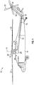
- FIG. 1 illustrates an exemplary rotary-winged aircraft 10 having a main rotor system 12, which rotates about a rotor axis 14.
- the aircraft 10 includes an airframe 16 which supports the main rotor system 12 as well as an extending tail 18 including a tail rotor 20.
- the main rotor system 12 includes a plurality of rotor blade assemblies 22 mounted to a rotor hub assembly 24.
- the main rotor system 12 is driven by a transmission 26.
- the transmission 26 includes a main gearbox 28 driven by one or more engines, illustrated schematically at 30.
- the main gearbox 28 and engines 30 are considered as part of the non-rotating frame of the aircraft 10.
- the main gearbox 28 may be interposed between one or more gas turbine engines 30 and the main rotor system 12.
- the aircraft further includes a tail rotor shaft 32 and one or more additional gearboxes, including typically an intermediate gearbox 33 and a tail rotor gearbox 34, connected to the transmission 26 to drive rotation of the tail rotor 20.
- additional gearboxes including typically an intermediate gearbox 33 and a tail rotor gearbox 34, connected to the transmission 26 to drive rotation of the tail rotor 20.
- vibration levels are a key indicator of component condition or health.
- a typical HUMS utilizes vibration data in its assessment, improving the type of data collected and the methods for analyzing the collected data improves the HUMS output, thus improving the accuracy and sensitivity of the assessment of the drivetrain components, which may be utilized to develop service intervals or maintenance schedules that align better with and more accurately reflect the drivetrain components' need for maintenance. This in turn may also be utilized for a more cost-effective maintenance schedule for the aircraft.
- the system 36 utilizes vibration data collected from vibration sensors 38, for example, accelerometers located at selected drivetrain components of the aircraft 10, and tachometer sensors 37 to sense rotational speed of selected drivetrain components.
- vibration data collected from vibration sensors 38, for example, accelerometers located at selected drivetrain components of the aircraft 10, and tachometer sensors 37 to sense rotational speed of selected drivetrain components.
- the system 36 seeks to collect other vibration data, referred to as load based transient vibration data 53, at high load or peak load operating conditions, which typically occur during transient operation of the aircraft 10 (e.g., during maneuvers or regimes).
- the system 36 utilizes physical load sensors 40 or estimates from virtual monitoring of loads 42 for loads monitoring 44 of key drive system loads such as torque to trigger vibration data acquisition during desired load-based capture windows (typically high-load maneuvers that are often transient in nature).
- the load sensors 40 can be any type of load sensor 40, including non-contact torque sensors, placed at the selected drivetrain components.
- the system 36 utilizes regime monitoring 43 using aircraft state data 41 to determine selected steady state conditions and trigger collection of data from the vibration sensors 38 and tachometer sensors 37.
- the system 36 may utilize a virtual monitoring of loads (VML) module 42, to trigger the collection of data from the vibration sensors 38 and/or tachometer sensors 37 via loads monitoring module 44.
- VML virtual monitoring of loads
- the VML module 42 utilizes aircraft state or parametric data measured by or derived from various aircraft sensors 39 and at times data from selected load sensors 40 to estimate loads via an empirical model.
- Said aircraft state or parametric data may include measured aircraft 10 operating states (e.g., forward flight speed, aircraft attitude, altitude, rates of change in operating states) or derived parameters (e.g., rates of change in operating states, regimes, aircraft gross weight, aircraft center of gravity,) calculated from other aircraft state parameters.
- the VML model 42 approach is advantageous in that no additional hardware in the form of torque sensors may be required.
- a data quality assurance (DQA) module 46 is utilized to flag suspect vibration sensors 38, for both the steady state vibration data 51 and the transient vibration data 53 since both data is from identical sensors, for maintenance activity and to prevent suspicious data from being utilized in mechanical diagnostics by the system 36.
- DQA data quality assurance
- the DQA module 46 is schematically shown in more detail in FIG. 3 .
- the DQA module 46 receives raw data, both the steady state vibration data 51 and the transient vibration data 53 as input from the data acquisition module 48.
- the DQA module 46 calculates a number of data condition indicators (CI's) 50, and the results are compared to data CI thresholds 52 for each respective data CI 50 to arrive at a data CI flag 54 for each data CI 50.
- the data CI's 50 include, but are not limited to, linear intercept, linear slope, mean at maximum jump, and random anomaly.
- the linear intercept data CI 50 is based on a linear fit of the raw data and using an intercept to detect a first order response seen in the data from intermittent connections.
- the linear slope data CI 50 is based on the linear fit of the raw data and using a slope to detect the first order response seen in the data from intermittent connections.
- the mean at maximum jump data CI 50 is intended to detect failure modes that would cause sensor power to be suddenly cut, dropping the signal, and then immediately reinstated, characterized by a first order response. Such faults may include intermittent open or shorted cabling or connectors.
- the CI calculation divides the time series data into two segments at the point of maximum jump. The difference in the mean of the two segments is then calculated. For healthy signals, this difference will be close to zero, but a more significant difference may be indicative of a fault.
- the random anomaly data CI 50 evaluates a signal for corruption based on a difference between the mean and the variance in the signal.
- the algorithm is intended to detect isolated random events, typically caused by wiring faults or packet loss.
- the data CI flags 54 are weighted and summed to arrive at a data health indicator (HI) 56.
- the data HI 56 is compared to a threshold and determination is made whether to trip a DQA flag 58 based on the comparison.
- the data from the data acquisition module 48 is processed to reduce data CI 50 variability during both regime-based steady-state and load-based (often transient) dynamic operation.
- One exemplary processing method is joint time-frequency analysis (JTFA) applied to the transient vibration data 53.
- JTFA joint time-frequency analysis
- the transient CI process module 60 uses the JTFA to transform the time-domain signal of the transient vibration data 53, in this case demodulated vibration, into a three dimensional representation of energy versus both time and frequency, thus expanding the dimensionality of the data, which is better suited for extracting high quality vibration features (CIs) from the data obtained from transient operational states, like those typically associated with high loads, of the aircraft 10.
- the transient CI process module 60 produces additional transient vibration data CI's 62.
- a noise reduction algorithm 64 is applied to the data. Although this technique may appear similar to time synchronous averaging processes commonly used for gears, in this instance the approach is applied to bearings. Referring now to FIG. 4 , the noise reduction algorithm 64 will be described in more detail. Initially, the raw steady state vibration data 51 is input into the noise reduction algorithm 64, and the shaft speed and period are checked at block 68.
- the raw vibration data 51 is segmented at block 70 with predefined block sizes, in this case a block size corresponding to one revolution, and a sliding window step.
- a phase compensation method is applied to align each segment of data with the first block of segmented data.
- the aligned blocks of data are transformed into spectra at block 74, which are then summed and averaged at block 76.
- the averaged spectrum is inversely transformed to a time waveform, i.e. a signal with improved signal to noise ratio, at block 80.
- the improved signal to noise ratio of the signal output of block 80 allows the bearing fault frequencies CI 50 calculated in steady state CI process module 65 to be more readily and consistently identifiable.
- the more reliable output of steady state CI process module 65 is a set of steady state CIs 67.
- embodiments of system 36 include a load filtering module 82 to trend drivetrain CIs by load level, or only for specific loads.
- the CIs are synchronized to the load data, and certain statistics of the load data are calculated, and the CIs then may be filtered by one or more of the calculated statistics.
- the statistics may include statistics (such as mean, maximum, median, etc. of the load above some predefined importance level) used to correlate instances in time of drivetrain component CIs to instances in time where the load exceeds a threshold; cumulative statistical parameters statistics (such as running mean, maximum, median, etc.
- the output of the load filtering module 82 is a set of filtered CIs 83.
- inventions of system 36 utilize a statistical change detection (SCD) module 84.
- SCD statistical change detection
- the SCD module 84 evaluates trends in vibration data, which while still may be well below traditional threshold for detecting a fault, show early trends of an incipient fault or a growing fault approaching the threshold.
- the SCD module 84 may evaluate the vibration data, filtered CIs 83, utilizing, for example, a mean trend test, a scatter test, and/or a mean gap test to establish new SCD-based CIs 85.
- a failure fault mode reasoning module 86 evaluates the processed vibration data from all of the sources, including the loads monitoring 44, SQA module 46, JFTA module 60, load filtering module 82, noise reduction algorithm 64, and SCD-based CIs 85. Due to the large number of CIs, components, and potentially complicated interactions between faults, it can be difficult to determine the best corrective action based upon typical information provided by a HUMS. A user of current HUMS information often has to simultaneously determine what, if any, component fault may exist from dozens of CI values and trends. Therefore, to reduce false alarms, improve diagnostics, and focus maintenance actions, a drive system fault-failure mode reasoner 86 is used.
- the reasoner combines and corroborates data from multiple sources to generate fault/failure mode rankings.
- the reasoner 86 is employed to infer the root cause of fault conditions with a degree of accuracy and confidence higher than what can be achieved from any single observation or CI, or even from a scalar health index that might be used to combine multiple CIs for a gearbox, for example.
- the rationale is that the information value of a network is greater than the sum of its individual parts.
- the reasoner module 86 utilizes a dependency model to calculate a ranked group of most likely causes or fault/failure modes with consideration of all of the available evidence. This ranked list of failure modes can then be used to determine the optimal remedial action, from a safety, cost, and effectiveness standpoint.
- the system 36 captures and utilizes data captured at both steady-state and high-load transient operating conditions to provide a more accurate indication of drivetrain component condition and earlier indication of incipient faults. Further, the captured data is processed by the system to ensure more accurate and reliable results are obtained. The system results in reductions in unscheduled maintenance by reducing ambiguities and false alarms associated with scheduled maintenance findings or on-aircraft exceedances. Operational safety and reliability are improved, because the more accurate diagnostics provide earlier fault indications prior to progression to failure. Finally more efficient maintenance and reduced cost of operation are achieved by higher accuracy, longer detection lead times that allow efficient maintenance planning and pre-ordering of high-value components not normally maintained in inventory.
Claims (15)
- Procédé de diagnostic d'un système d'entraînement d'un aéronef comprenant :la capture de données de vibration de composant de transmission de charge élevée (51) dans des conditions de fonctionnement en régime permanent sélectionnées et de données de vibration transitoire basées sur la charge (53) dans des conditions de fonctionnement transitoire de charge élevée sélectionnées de l'aéronef en utilisant des capteurs de charge physique (40) ou des estimations à partir d'une surveillance virtuelle de charges (42) pour la surveillance de charges (44) de charges de système d'entraînement à clé pour déclencher l'acquisition de données de vibration pendant les fenêtres de capture basées sur la charge souhaitées ;le traitement des données de vibration capturées pour améliorer la fiabilité et/ou l'exactitude des données de vibration capturées ; etl'utilisation des données de vibration traitées pour fournir une évaluation de santé des composants de transmission et effectuer une détection plus précoce des débuts de défaut.
- Procédé selon la revendication 1, comprenant en outre :la détection de charge (40) au niveau d'un ou de plusieurs composants de transmission ; etle déclenchement de la capture de données de vibration de composant de transmission quand la charge détectée indique un mode de fonctionnement sélectionné pour la capture de données ; et/oucomprenant en outre :la surveillance de données de paramètres de fonctionnement de l'aéronef ;l'utilisation d'un module virtuel de surveillance de charges (42)' pour estimer une charge d'aéronef sur la base des données de paramètres ;le déclenchement de la capture de données de vibration de composant de transmission lorsque la charge estimée indique un mode de fonctionnement sélectionné pour la capture de données.
- Procédé selon l'une quelconque des revendications 1 et 2, comprenant en outre l'utilisation d'un module de filtrage de charge (82) pour mettre en corrélation les données de vibration et les indicateurs de condition associés avec les paramètres de charge d'aéronef, en particulier dans lequel les paramètres de charge d'aéronef comprennent des paramètres de dépassement les plus proches, des paramètres de dépassement cumulatifs et des paramètres de fenêtre de capture.
- Procédé selon l'une quelconque des revendications 1 à 3, comprenant en outre l'utilisation d'un module d'évaluation de qualité des données (46) pour signaler les capteurs de vibration suspecte (37, 38, 39, 40) fournissant des données de vibration et pour empêcher les données de vibration suspecte d'être utilisées dans le calcul de l'évaluation de santé.
- Procédé selon l'une quelconque des revendications 1 à 4, comprenant en outre :
l'utilisation de procédés de traitement de signal dynamique ou transitoire pour réduire la variabilité dans les données de vibration de charge élevée et dans les indicateurs de condition calculés, en particulier comprenant en outre l'utilisation de l'analyse temps-fréquence conjointe pour réduire la variabilité dans les données de vibration et les indicateurs de condition calculés. - Procédé selon l'une quelconque des revendications 1 à 5, comprenant en outre l'application d'un algorithme de réduction de bruit aux données capturées pendant les conditions de fonctionnement en régime permanent.
- Procédé selon l'une quelconque des revendications 1 à 6, comprenant en outre l'utilisation d'un module de détection de changement statistique (SCD) (84, 85) pour identifier les performances dans les données de vibration collectées indiquant un comportement de système irrégulier qui indique une condition de début de défaut.
- Procédé selon l'une quelconque des revendications 1 à 7, comprenant en outre l'utilisation de procédés de raisonnement pour combiner ou fusionner les preuves de début de défaut, de défaut d'ampleur croissante ou de défaut critique à partir d'une variété de procédés d'analyse de données et d'indicateurs de condition associés, comprenant des indicateurs de condition de vibration en régime permanent, des indicateurs de condition de vibration transitoire et des indicateurs d'assurance qualité des données.
- Système de surveillance de santé (36) pour composants de transmission d'un aéronef comprenant :une pluralité de capteurs de vibration (37, 38, 39, 40) disposée au niveau de composants de transmission d'un aéronef pour capturer des données de vibration de composant de transmission (51) dans des conditions de fonctionnement en régime permanent sélectionnées et des données de vibration transitoire basées sur la charge (53) dans des conditions de fonctionnement transitoire de charge élevée de l'aéronef en utilisant des capteurs de charge physique (40) ou des estimations à partir d'une surveillance virtuelle de charges (42) pour la surveillance de charges (44) de charges de système d'entraînement à clé pour déclencher l'acquisition de données de vibration pendant les fenêtres de capture basées sur la charge souhaitées ;un ou plusieurs modules de traitement (60) pour traiter les données de vibration capturées pour améliorer la fiabilité et/ou l'exactitude des données capturées ; etun module de raisonnement de défaut (86) pour calculer un indicateur de santé des composants de transmission.
- Système selon la revendication 9, comprenant en outre une pluralité de capteurs de charge (40) disposée au niveau d'un ou de plusieurs composants de transmission, la capture des données de vibration de composant de transmission étant déclenchée lorsqu'un couple détecté indique le fonctionnement transitoire de l'aéronef, et/ou
comprenant en outre un module virtuel de surveillance de charges (42) pour estimer une charge d'aéronef sur la base de données de paramètres collectées de l'aéronef, les données de vibration de composant de transmission étant capturées lorsque la charge estimée indique le fonctionnement transitoire de l'aéronef. - Système selon l'une quelconque des revendications 9 et 10, comprenant en outre un module d'évaluation de qualité des données (46) pour signaler les capteurs de vibration suspecte fournissant des données de vibration et pour empêcher les données de vibration suspecte d'être utilisées dans le calcul de l'indicateur de santé.
- Système selon l'une quelconque des revendications 9 à 11, comprenant en outre le traitement des données de vibration capturées pour réduire la variabilité dans les données de vibration, en particulier comprenant en outre l'utilisation de l'analyse temps-fréquence conjointe pour réduire la variabilité dans les données de vibration.
- Système selon l'une quelconque des revendications 9 à 12, comprenant en outre un algorithme de réduction de bruit pour améliorer le rapport signal sur bruit des données de vibration capturées.
- Système selon l'une quelconque des revendications 9 à 13, comprenant en outre un module de filtrage de charge (82) pour mettre en corrélation les données de vibration avec les paramètres de charge d'aéronef, en particulier dans lequel les paramètres de charge d'aéronef comprennent des paramètres de dépassement les plus proches, des paramètres de dépassement cumulatifs et des paramètres de fenêtre de capture.
- Système selon l'une quelconque des revendications 9 à 14, comprenant en outre un module de détection de changement statistique (84, 85) pour identifier les performances dans les données de vibration collectées indiquant un comportement de système irrégulier qui indique une condition de défaut proche.
Applications Claiming Priority (2)
| Application Number | Priority Date | Filing Date | Title |
|---|---|---|---|
| US201461974101P | 2014-04-02 | 2014-04-02 | |
| PCT/US2015/024013 WO2015153845A1 (fr) | 2014-04-02 | 2015-04-02 | Système et procédé de diagnostic amélioré d'un système d'entraînement |
Publications (3)
| Publication Number | Publication Date |
|---|---|
| EP3126243A1 EP3126243A1 (fr) | 2017-02-08 |
| EP3126243A4 EP3126243A4 (fr) | 2017-10-11 |
| EP3126243B1 true EP3126243B1 (fr) | 2018-12-26 |
Family
ID=54241279
Family Applications (1)
| Application Number | Title | Priority Date | Filing Date |
|---|---|---|---|
| EP15772472.5A Active EP3126243B1 (fr) | 2014-04-02 | 2015-04-02 | Système et procédé de diagnostic amélioré d'un système d'entraînement |
Country Status (3)
| Country | Link |
|---|---|
| US (1) | US10360737B2 (fr) |
| EP (1) | EP3126243B1 (fr) |
| WO (1) | WO2015153845A1 (fr) |
Families Citing this family (15)
| Publication number | Priority date | Publication date | Assignee | Title |
|---|---|---|---|---|
| EP3159851B1 (fr) | 2015-10-23 | 2024-02-14 | Safran Landing Systems UK Ltd | Système de surveillance de la santé et de l'utilisation d'un aéronef et procédé de déclenchement |
| CN105426679B (zh) * | 2015-11-20 | 2018-05-15 | 株洲南车时代电气股份有限公司 | 一种基于故障隔离与恢复算法的机车速度计算方法 |
| US10380810B2 (en) | 2016-08-17 | 2019-08-13 | Bell Helicopter Textron Inc. | Diagnostic method, system and device for a rotorcraft drive system |
| US10643405B2 (en) * | 2016-08-17 | 2020-05-05 | Bell Helicopter Textron Inc. | Diagnostic method, system and device for a rotorcraft drive system |
| US10424134B2 (en) | 2016-08-17 | 2019-09-24 | Bell Helicopter Textron Inc. | Diagnostic method, system and device for a rotorcraft drive system |
| US10464689B2 (en) | 2016-08-17 | 2019-11-05 | Bell Helicopter Textron Inc. | Diagnostic method, system and device for a rotorcraft drive system |
| US10657735B2 (en) | 2017-10-09 | 2020-05-19 | Textron Innovations Inc. | System and method for adaptable trend detection for component condition indicator data |
| US10580232B2 (en) * | 2018-08-06 | 2020-03-03 | GM Global Technology Operations LLC | Apparatus and method that diagnose vehicle health condition |
| US10832196B2 (en) | 2018-08-31 | 2020-11-10 | Kinaxis Inc. | Analysis and correction of supply chain design through machine learning |
| US10846651B2 (en) * | 2018-08-31 | 2020-11-24 | Kinaxis Inc. | Analysis and correction of supply chain design through machine learning |
| US11287310B2 (en) * | 2019-04-23 | 2022-03-29 | Computational Systems, Inc. | Waveform gap filling |
| CN110697075B (zh) * | 2019-09-29 | 2022-11-25 | 中国直升机设计研究所 | 一种直升机hums振动阈值生成方法 |
| US11618585B2 (en) | 2019-10-10 | 2023-04-04 | Ge Aviation Systems Limited | Integrated system for improved vehicle maintenance and safety |
| WO2021115635A1 (fr) * | 2019-12-13 | 2021-06-17 | Eaton Intelligent Power Limited | Surveillance de la santé d'un système d'actionneurs |
| US11341790B2 (en) * | 2020-01-15 | 2022-05-24 | Textron Innovations Inc. | Gearbox internal sensor integration |
Family Cites Families (20)
| Publication number | Priority date | Publication date | Assignee | Title |
|---|---|---|---|---|
| US3464651A (en) * | 1967-05-02 | 1969-09-02 | United Aircraft Corp | Rotor load proportioner for a compound helicopter |
| WO1995002519A1 (fr) * | 1993-07-15 | 1995-01-26 | Onan Corporation | Groupe generateur equilibre commande par moteur |
| US7027953B2 (en) * | 2002-12-30 | 2006-04-11 | Rsl Electronics Ltd. | Method and system for diagnostics and prognostics of a mechanical system |
| JP4610300B2 (ja) * | 2004-11-02 | 2011-01-12 | 富士通テン株式会社 | 車両用制御装置および車両用制御方法 |
| US7346461B2 (en) * | 2005-09-30 | 2008-03-18 | The United States Of America As Represented By The Administrator Of The National Aeronautics And Space Administration | System and method of analyzing vibrations and identifying failure signatures in the vibrations |
| US8682509B2 (en) * | 2007-02-16 | 2014-03-25 | Honeywell International Inc. | Vehicle monitoring system |
| US8131420B2 (en) * | 2008-02-27 | 2012-03-06 | Simmonds Precision Products, Inc. | Vehicle health and usage monitoring system and method |
| US7684936B2 (en) | 2008-05-07 | 2010-03-23 | Simmonds Precision Products, Inc. | Method, apparatus and computer program product for determining a future time of a component |
| US20100161244A1 (en) * | 2008-12-18 | 2010-06-24 | Sikorsky Aircraft Corporation | Method and apparatus for monitoring structural health |
| GB0902730D0 (en) * | 2009-02-18 | 2009-04-01 | Oxford Biosignals Ltd | Method and apparatus for monitoring and analyzing vibrations in rotary machines |
| WO2011163316A2 (fr) * | 2010-06-25 | 2011-12-29 | Sikorsky Aircraft Corporation | Procédé et système de détection de défaillance de bielles de poussée |
| JP5522259B2 (ja) * | 2010-08-25 | 2014-06-18 | 新日鐵住金株式会社 | 鉄道車両の振動成分加速度推定装置および振動成分加速度推定方法 |
| WO2013120103A1 (fr) * | 2012-02-10 | 2013-08-15 | Appareo Systems, Llc | Système de contrôle d'état et d'utilisation de structures adaptable en termes de fréquences |
| GB2514980B (en) * | 2012-04-10 | 2018-12-19 | Lockheed Corp | Efficient health management, diagnosis and prognosis of a machine |
| CN105593438B (zh) * | 2013-05-31 | 2019-07-05 | 伊顿智能动力有限公司 | 用于通过平衡保护来降低动臂跳动的液压系统及方法 |
| WO2015031821A1 (fr) * | 2013-08-30 | 2015-03-05 | Eaton Corporation | Procédé et système de commande pour l'utilisation d'une paire de soupapes de dosage à commande hydraulique indépendantes pour réduire des oscillations de flèche |
| EP3069030B1 (fr) * | 2013-11-14 | 2020-12-30 | Eaton Intelligent Power Limited | Mécanisme de commande pilote pour réduction de rebond de flèche |
| WO2015073330A1 (fr) * | 2013-11-14 | 2015-05-21 | Eaton Corporation | Stratégie de commande à des fins de réduction d'oscillation de flèche |
| US9944400B2 (en) * | 2014-02-11 | 2018-04-17 | Sikorsky Aircraft Corporation | Adaptive engine acceleration for accessory loads |
| CN106661894B (zh) * | 2014-07-15 | 2019-12-10 | 伊顿公司 | 实现悬臂弹跳减少以及防止液压系统中的非指令运动的方法和设备 |
-
2015
- 2015-04-02 WO PCT/US2015/024013 patent/WO2015153845A1/fr active Application Filing
- 2015-04-02 US US15/301,152 patent/US10360737B2/en active Active
- 2015-04-02 EP EP15772472.5A patent/EP3126243B1/fr active Active
Non-Patent Citations (1)
| Title |
|---|
| None * |
Also Published As
| Publication number | Publication date |
|---|---|
| EP3126243A4 (fr) | 2017-10-11 |
| US10360737B2 (en) | 2019-07-23 |
| WO2015153845A1 (fr) | 2015-10-08 |
| EP3126243A1 (fr) | 2017-02-08 |
| US20170011560A1 (en) | 2017-01-12 |
Similar Documents
| Publication | Publication Date | Title |
|---|---|---|
| EP3126243B1 (fr) | Système et procédé de diagnostic amélioré d'un système d'entraînement | |
| US11105712B2 (en) | Integrated vibe/ODM fusion and trending analysis for prognostic health management of engine bearing | |
| EP3221579B1 (fr) | Procédé et système de contrôle d'état de turbine éolienne | |
| EP2585716B1 (fr) | Procédé permettant d'effectuer une surveillance d'état dans un parc éolien | |
| EP2585371B1 (fr) | Procédé et système de détection de défaillance de bielles de poussée | |
| CN103998775B (zh) | 用于确定风能源设备的转子叶片的机械损坏的方法 | |
| EP2730898B1 (fr) | Roulement à billes, boîtier comprenant un ensemble de roulements, procédé associé et programme informatique | |
| CN107884214B (zh) | 一种列车走行部部件故障多参数综合决策方法及装置 | |
| CN107061183A (zh) | 一种海上风电机组的自动化故障诊断方法 | |
| US10388087B2 (en) | System and method for improved health management and maintenance decision support | |
| CA2875071A1 (fr) | Procede et systeme de test de l'integrite operationnelle d'un equipement de forage | |
| EP3222516B1 (fr) | Équilibrage d'hélice à l'aide de données en vol | |
| CN113286944B (zh) | 一种用于监测叶根紧固件的健康状态的方法及系统 | |
| EP2672164B1 (fr) | Système et procédé de détection d'initiation d'éclatement et définition de fin de vie de composants dans un moteur | |
| US9897479B2 (en) | Assembly and method of component monitoring | |
| US8955372B2 (en) | Systems and methods for continuous pressure change monitoring in turbine compressors | |
| CN111795824B (zh) | 机械动力系统故障诊断方法及系统 | |
| US11010568B2 (en) | Method for detecting an incipient damage in a bearing | |
| Dempsey et al. | Comparison of test stand and helicopter oil cooler bearing condition indicators | |
| EP3296513B1 (fr) | Surveillance de l'état d'une hélice | |
| Shen et al. | Design on the health and usage monitoring system | |
| Antolick et al. | Application of Advanced Vibration Techniques for Enhancing Bearing Diagnostics on a HUMS-Equipped Fleet | |
| Dempsey et al. | Rotorcraft Health Management | |
| Mathew | A Framework and Breakdown of Health & Usage | |
| Camerini et al. | Health monitoring of helicopter drive train components based on support vector data description |
Legal Events
| Date | Code | Title | Description |
|---|---|---|---|
| STAA | Information on the status of an ep patent application or granted ep patent |
Free format text: STATUS: THE INTERNATIONAL PUBLICATION HAS BEEN MADE |
|
| PUAI | Public reference made under article 153(3) epc to a published international application that has entered the european phase |
Free format text: ORIGINAL CODE: 0009012 |
|
| STAA | Information on the status of an ep patent application or granted ep patent |
Free format text: STATUS: REQUEST FOR EXAMINATION WAS MADE |
|
| 17P | Request for examination filed |
Effective date: 20161026 |
|
| AK | Designated contracting states |
Kind code of ref document: A1 Designated state(s): AL AT BE BG CH CY CZ DE DK EE ES FI FR GB GR HR HU IE IS IT LI LT LU LV MC MK MT NL NO PL PT RO RS SE SI SK SM TR |
|
| AX | Request for extension of the european patent |
Extension state: BA ME |
|
| DAV | Request for validation of the european patent (deleted) | ||
| DAX | Request for extension of the european patent (deleted) | ||
| A4 | Supplementary search report drawn up and despatched |
Effective date: 20170908 |
|
| RIC1 | Information provided on ipc code assigned before grant |
Ipc: G07C 5/00 20060101ALI20170904BHEP Ipc: G05B 23/02 20060101ALI20170904BHEP Ipc: G01M 17/00 20060101ALI20170904BHEP Ipc: B64D 45/00 20060101AFI20170904BHEP |
|
| GRAP | Despatch of communication of intention to grant a patent |
Free format text: ORIGINAL CODE: EPIDOSNIGR1 |
|
| STAA | Information on the status of an ep patent application or granted ep patent |
Free format text: STATUS: GRANT OF PATENT IS INTENDED |
|
| INTG | Intention to grant announced |
Effective date: 20180709 |
|
| GRAS | Grant fee paid |
Free format text: ORIGINAL CODE: EPIDOSNIGR3 |
|
| GRAA | (expected) grant |
Free format text: ORIGINAL CODE: 0009210 |
|
| STAA | Information on the status of an ep patent application or granted ep patent |
Free format text: STATUS: THE PATENT HAS BEEN GRANTED |
|
| AK | Designated contracting states |
Kind code of ref document: B1 Designated state(s): AL AT BE BG CH CY CZ DE DK EE ES FI FR GB GR HR HU IE IS IT LI LT LU LV MC MK MT NL NO PL PT RO RS SE SI SK SM TR |
|
| REG | Reference to a national code |
Ref country code: GB Ref legal event code: FG4D |
|
| REG | Reference to a national code |
Ref country code: CH Ref legal event code: EP |
|
| REG | Reference to a national code |
Ref country code: AT Ref legal event code: REF Ref document number: 1081059 Country of ref document: AT Kind code of ref document: T Effective date: 20190115 |
|
| REG | Reference to a national code |
Ref country code: DE Ref legal event code: R096 Ref document number: 602015022401 Country of ref document: DE |
|
| REG | Reference to a national code |
Ref country code: IE Ref legal event code: FG4D |
|
| PG25 | Lapsed in a contracting state [announced via postgrant information from national office to epo] |
Ref country code: LT Free format text: LAPSE BECAUSE OF FAILURE TO SUBMIT A TRANSLATION OF THE DESCRIPTION OR TO PAY THE FEE WITHIN THE PRESCRIBED TIME-LIMIT Effective date: 20181226 Ref country code: BG Free format text: LAPSE BECAUSE OF FAILURE TO SUBMIT A TRANSLATION OF THE DESCRIPTION OR TO PAY THE FEE WITHIN THE PRESCRIBED TIME-LIMIT Effective date: 20190326 Ref country code: NO Free format text: LAPSE BECAUSE OF FAILURE TO SUBMIT A TRANSLATION OF THE DESCRIPTION OR TO PAY THE FEE WITHIN THE PRESCRIBED TIME-LIMIT Effective date: 20190326 Ref country code: FI Free format text: LAPSE BECAUSE OF FAILURE TO SUBMIT A TRANSLATION OF THE DESCRIPTION OR TO PAY THE FEE WITHIN THE PRESCRIBED TIME-LIMIT Effective date: 20181226 Ref country code: LV Free format text: LAPSE BECAUSE OF FAILURE TO SUBMIT A TRANSLATION OF THE DESCRIPTION OR TO PAY THE FEE WITHIN THE PRESCRIBED TIME-LIMIT Effective date: 20181226 Ref country code: HR Free format text: LAPSE BECAUSE OF FAILURE TO SUBMIT A TRANSLATION OF THE DESCRIPTION OR TO PAY THE FEE WITHIN THE PRESCRIBED TIME-LIMIT Effective date: 20181226 |
|
| REG | Reference to a national code |
Ref country code: NL Ref legal event code: MP Effective date: 20181226 |
|
| REG | Reference to a national code |
Ref country code: LT Ref legal event code: MG4D |
|
| PG25 | Lapsed in a contracting state [announced via postgrant information from national office to epo] |
Ref country code: GR Free format text: LAPSE BECAUSE OF FAILURE TO SUBMIT A TRANSLATION OF THE DESCRIPTION OR TO PAY THE FEE WITHIN THE PRESCRIBED TIME-LIMIT Effective date: 20190327 Ref country code: RS Free format text: LAPSE BECAUSE OF FAILURE TO SUBMIT A TRANSLATION OF THE DESCRIPTION OR TO PAY THE FEE WITHIN THE PRESCRIBED TIME-LIMIT Effective date: 20181226 Ref country code: SE Free format text: LAPSE BECAUSE OF FAILURE TO SUBMIT A TRANSLATION OF THE DESCRIPTION OR TO PAY THE FEE WITHIN THE PRESCRIBED TIME-LIMIT Effective date: 20181226 Ref country code: AL Free format text: LAPSE BECAUSE OF FAILURE TO SUBMIT A TRANSLATION OF THE DESCRIPTION OR TO PAY THE FEE WITHIN THE PRESCRIBED TIME-LIMIT Effective date: 20181226 |
|
| REG | Reference to a national code |
Ref country code: AT Ref legal event code: MK05 Ref document number: 1081059 Country of ref document: AT Kind code of ref document: T Effective date: 20181226 |
|
| PG25 | Lapsed in a contracting state [announced via postgrant information from national office to epo] |
Ref country code: NL Free format text: LAPSE BECAUSE OF FAILURE TO SUBMIT A TRANSLATION OF THE DESCRIPTION OR TO PAY THE FEE WITHIN THE PRESCRIBED TIME-LIMIT Effective date: 20181226 |
|
| PG25 | Lapsed in a contracting state [announced via postgrant information from national office to epo] |
Ref country code: PL Free format text: LAPSE BECAUSE OF FAILURE TO SUBMIT A TRANSLATION OF THE DESCRIPTION OR TO PAY THE FEE WITHIN THE PRESCRIBED TIME-LIMIT Effective date: 20181226 Ref country code: PT Free format text: LAPSE BECAUSE OF FAILURE TO SUBMIT A TRANSLATION OF THE DESCRIPTION OR TO PAY THE FEE WITHIN THE PRESCRIBED TIME-LIMIT Effective date: 20190426 Ref country code: CZ Free format text: LAPSE BECAUSE OF FAILURE TO SUBMIT A TRANSLATION OF THE DESCRIPTION OR TO PAY THE FEE WITHIN THE PRESCRIBED TIME-LIMIT Effective date: 20181226 Ref country code: ES Free format text: LAPSE BECAUSE OF FAILURE TO SUBMIT A TRANSLATION OF THE DESCRIPTION OR TO PAY THE FEE WITHIN THE PRESCRIBED TIME-LIMIT Effective date: 20181226 |
|
| PG25 | Lapsed in a contracting state [announced via postgrant information from national office to epo] |
Ref country code: SK Free format text: LAPSE BECAUSE OF FAILURE TO SUBMIT A TRANSLATION OF THE DESCRIPTION OR TO PAY THE FEE WITHIN THE PRESCRIBED TIME-LIMIT Effective date: 20181226 Ref country code: SM Free format text: LAPSE BECAUSE OF FAILURE TO SUBMIT A TRANSLATION OF THE DESCRIPTION OR TO PAY THE FEE WITHIN THE PRESCRIBED TIME-LIMIT Effective date: 20181226 Ref country code: RO Free format text: LAPSE BECAUSE OF FAILURE TO SUBMIT A TRANSLATION OF THE DESCRIPTION OR TO PAY THE FEE WITHIN THE PRESCRIBED TIME-LIMIT Effective date: 20181226 Ref country code: IS Free format text: LAPSE BECAUSE OF FAILURE TO SUBMIT A TRANSLATION OF THE DESCRIPTION OR TO PAY THE FEE WITHIN THE PRESCRIBED TIME-LIMIT Effective date: 20190426 Ref country code: EE Free format text: LAPSE BECAUSE OF FAILURE TO SUBMIT A TRANSLATION OF THE DESCRIPTION OR TO PAY THE FEE WITHIN THE PRESCRIBED TIME-LIMIT Effective date: 20181226 |
|
| REG | Reference to a national code |
Ref country code: DE Ref legal event code: R097 Ref document number: 602015022401 Country of ref document: DE |
|
| PG25 | Lapsed in a contracting state [announced via postgrant information from national office to epo] |
Ref country code: AT Free format text: LAPSE BECAUSE OF FAILURE TO SUBMIT A TRANSLATION OF THE DESCRIPTION OR TO PAY THE FEE WITHIN THE PRESCRIBED TIME-LIMIT Effective date: 20181226 Ref country code: DK Free format text: LAPSE BECAUSE OF FAILURE TO SUBMIT A TRANSLATION OF THE DESCRIPTION OR TO PAY THE FEE WITHIN THE PRESCRIBED TIME-LIMIT Effective date: 20181226 |
|
| PLBE | No opposition filed within time limit |
Free format text: ORIGINAL CODE: 0009261 |
|
| STAA | Information on the status of an ep patent application or granted ep patent |
Free format text: STATUS: NO OPPOSITION FILED WITHIN TIME LIMIT |
|
| REG | Reference to a national code |
Ref country code: CH Ref legal event code: PL |
|
| 26N | No opposition filed |
Effective date: 20190927 |
|
| REG | Reference to a national code |
Ref country code: BE Ref legal event code: MM Effective date: 20190430 |
|
| PG25 | Lapsed in a contracting state [announced via postgrant information from national office to epo] |
Ref country code: LU Free format text: LAPSE BECAUSE OF NON-PAYMENT OF DUE FEES Effective date: 20190402 Ref country code: MC Free format text: LAPSE BECAUSE OF FAILURE TO SUBMIT A TRANSLATION OF THE DESCRIPTION OR TO PAY THE FEE WITHIN THE PRESCRIBED TIME-LIMIT Effective date: 20181226 |
|
| PG25 | Lapsed in a contracting state [announced via postgrant information from national office to epo] |
Ref country code: CH Free format text: LAPSE BECAUSE OF NON-PAYMENT OF DUE FEES Effective date: 20190430 Ref country code: LI Free format text: LAPSE BECAUSE OF NON-PAYMENT OF DUE FEES Effective date: 20190430 |
|
| PG25 | Lapsed in a contracting state [announced via postgrant information from national office to epo] |
Ref country code: BE Free format text: LAPSE BECAUSE OF NON-PAYMENT OF DUE FEES Effective date: 20190430 Ref country code: SI Free format text: LAPSE BECAUSE OF FAILURE TO SUBMIT A TRANSLATION OF THE DESCRIPTION OR TO PAY THE FEE WITHIN THE PRESCRIBED TIME-LIMIT Effective date: 20181226 |
|
| PG25 | Lapsed in a contracting state [announced via postgrant information from national office to epo] |
Ref country code: TR Free format text: LAPSE BECAUSE OF FAILURE TO SUBMIT A TRANSLATION OF THE DESCRIPTION OR TO PAY THE FEE WITHIN THE PRESCRIBED TIME-LIMIT Effective date: 20181226 |
|
| PG25 | Lapsed in a contracting state [announced via postgrant information from national office to epo] |
Ref country code: IE Free format text: LAPSE BECAUSE OF NON-PAYMENT OF DUE FEES Effective date: 20190402 |
|
| PG25 | Lapsed in a contracting state [announced via postgrant information from national office to epo] |
Ref country code: CY Free format text: LAPSE BECAUSE OF FAILURE TO SUBMIT A TRANSLATION OF THE DESCRIPTION OR TO PAY THE FEE WITHIN THE PRESCRIBED TIME-LIMIT Effective date: 20181226 |
|
| PG25 | Lapsed in a contracting state [announced via postgrant information from national office to epo] |
Ref country code: HU Free format text: LAPSE BECAUSE OF FAILURE TO SUBMIT A TRANSLATION OF THE DESCRIPTION OR TO PAY THE FEE WITHIN THE PRESCRIBED TIME-LIMIT; INVALID AB INITIO Effective date: 20150402 Ref country code: MT Free format text: LAPSE BECAUSE OF FAILURE TO SUBMIT A TRANSLATION OF THE DESCRIPTION OR TO PAY THE FEE WITHIN THE PRESCRIBED TIME-LIMIT Effective date: 20181226 |
|
| PG25 | Lapsed in a contracting state [announced via postgrant information from national office to epo] |
Ref country code: MK Free format text: LAPSE BECAUSE OF FAILURE TO SUBMIT A TRANSLATION OF THE DESCRIPTION OR TO PAY THE FEE WITHIN THE PRESCRIBED TIME-LIMIT Effective date: 20181226 |
|
| PGFP | Annual fee paid to national office [announced via postgrant information from national office to epo] |
Ref country code: IT Payment date: 20230419 Year of fee payment: 9 Ref country code: FR Payment date: 20230425 Year of fee payment: 9 Ref country code: DE Payment date: 20230427 Year of fee payment: 9 |
|
| PGFP | Annual fee paid to national office [announced via postgrant information from national office to epo] |
Ref country code: GB Payment date: 20230427 Year of fee payment: 9 |