EP3126197B1 - Winter wiper assembly - Google Patents
Winter wiper assembly Download PDFInfo
- Publication number
- EP3126197B1 EP3126197B1 EP15772912.0A EP15772912A EP3126197B1 EP 3126197 B1 EP3126197 B1 EP 3126197B1 EP 15772912 A EP15772912 A EP 15772912A EP 3126197 B1 EP3126197 B1 EP 3126197B1
- Authority
- EP
- European Patent Office
- Prior art keywords
- wiper assembly
- wiping
- airfoil
- wiper
- set forth
- Prior art date
- Legal status (The legal status is an assumption and is not a legal conclusion. Google has not performed a legal analysis and makes no representation as to the accuracy of the status listed.)
- Active
Links
Images


Classifications
-
- B—PERFORMING OPERATIONS; TRANSPORTING
- B60—VEHICLES IN GENERAL
- B60S—SERVICING, CLEANING, REPAIRING, SUPPORTING, LIFTING, OR MANOEUVRING OF VEHICLES, NOT OTHERWISE PROVIDED FOR
- B60S1/00—Cleaning of vehicles
- B60S1/02—Cleaning windscreens, windows or optical devices
- B60S1/04—Wipers or the like, e.g. scrapers
- B60S1/32—Wipers or the like, e.g. scrapers characterised by constructional features of wiper blade arms or blades
- B60S1/38—Wiper blades
- B60S1/3806—Means, or measures taken, for influencing the aerodynamic quality of the wiper blades
- B60S1/381—Spoilers mounted on the squeegee or on the vertebra
-
- B—PERFORMING OPERATIONS; TRANSPORTING
- B60—VEHICLES IN GENERAL
- B60S—SERVICING, CLEANING, REPAIRING, SUPPORTING, LIFTING, OR MANOEUVRING OF VEHICLES, NOT OTHERWISE PROVIDED FOR
- B60S1/00—Cleaning of vehicles
- B60S1/02—Cleaning windscreens, windows or optical devices
- B60S1/04—Wipers or the like, e.g. scrapers
- B60S1/32—Wipers or the like, e.g. scrapers characterised by constructional features of wiper blade arms or blades
- B60S1/38—Wiper blades
- B60S1/3848—Flat-type wiper blade, i.e. without harness
- B60S1/3874—Flat-type wiper blade, i.e. without harness with a reinforcing vertebra
- B60S1/3875—Flat-type wiper blade, i.e. without harness with a reinforcing vertebra rectangular section
- B60S1/3881—Flat-type wiper blade, i.e. without harness with a reinforcing vertebra rectangular section in additional element, e.g. spoiler
Definitions
- the present invention relates generally to wiper assemblies for wiper systems, and more specifically, to winter wiper assemblies.
- wiper assembly sometimes referred to as a wiper blade mounted to a wiper arm which, in turn, is mounted adjacent to a surface to be wiped, such as a windshield of a vehicle, and pivotally driven to impart reciprocal motion to the wiper assembly across the windshield.
- the wiper assembly typically includes a rubber wiping element that contacts the windshield across the surface to be wiped.
- the wiper assembly often incorporates one or more metal strips that act to reinforce the wiping element and facilitate wiping contact by the wiping element across what is typically a curved glass surface.
- the wiper assembly also typically includes a coupler that attaches to and supports the one or more metal strips, and an adapter attached to the coupler.
- the adapter allows the wiper assembly to be releasably attached to the wiper arm.
- the wiper arm delivers a downward force to the wiper assembly that is distributed thereacross, pressing the wiper assembly into contact with the windshield.
- the wiper assembly also typically includes an airfoil that attaches to the metal strips, and a pair of end caps located at distal ends of the wiper assembly.
- the airfoil is often formed from plastic or rubber and is used to prevent the wiper assembly from lifting off the windshield.
- the end caps are typically used to prevent the airfoil from sliding off the metal strips in operation.
- each of the components of a wiper assembly of the type described above must cooperate to effectively clean a surface to be wiped.
- each of the components must be designed not only to facilitate an improved wipe quality, but also so as to perform well in different weather and driving conditions.
- snow and ice tend to accumulate on the wiper assembly, leading to an undesirable decrease in wiping performance and sometimes causing the wiper assembly to freeze to the windshield.
- snow and ice typically first adhere to the metal strips and exacerbate accumulation along the length of the wiper assembly.
- wiper assemblies known in the related art have generally performed well for their intended purpose, there remains a need in the art for a wiper system that has superior operational characteristics, reduces the cost of manufacturing the assembly, and provides an increased resistance to accumulation of snow and ice in winter driving conditions.
- the present invention overcomes the disadvantages in the related art in a wiper assembly that includes at least one elongated support element, a wiping element, and an airfoil.
- the wiping element is adapted to contact a surface to be wiped.
- the wiping element has a head portion operatively attached to the support element, a wiping portion spaced from the head portion, and a pair of opposed grooves disposed between the head portion and the wiping portion.
- the airfoil has a body with a lower surface and a slot spaced from the lower surface for accommodating the support element therein.
- the body of the airfoil also has a channel extending from the lower surface to the slot, where the channel defines a pair of opposed shelves.
- the body of the airfoil also includes a pair of concealing members depending from the shelves. The concealing members are at least partially disposed in the grooves of the wiping element so as to substantially conceal the support element within the body of the airfoil.
- the present invention is directed toward a wiper assembly that includes a wiping element, at least one elongated support element, a pair of end caps, and at least one airfoil.
- the wiping element is adapted to contact a surface to be wiped.
- the wiping element has a head portion, a wiping portion spaced from the head portion, and a pair of opposed grooves disposed between the head portion and the wiping portion.
- the support element is operatively attached to the head portion of the wiping element and has opposed longitudinal ends.
- the end caps are operatively attached to the longitudinal ends of the support element.
- the airfoil is operatively attached to the support element.
- the airfoil has a body with a lower surface and a slot spaced from the lower surface for accommodating the support element therein.
- the body of the airfoil also has a channel extending from the lower surface to the slot, where the channel defines a pair of opposed shelves.
- the body of the airfoil also includes a pair of concealing members depending from the shelves. The concealing members are at least partially disposed in the grooves of the wiping element so as to substantially conceal the support element within the body of the airfoil.
- the wiper assembly of the present invention effectively cleans a surface to be wiped and, at the same time, provides an increased resistance to accumulation of snow and ice in winter driving conditions. Further, the wiper assembly of the present invention provides advantages related to manufacturing and component assembly.
- the vehicle 10 includes a cowl 12, a roof 14, and a pair of laterally spaced front A-pillars 16 extending between the roof 14 and the cowl 12.
- the A-pillars 16, roof 14, and cowl 12 cooperate to define a generally rectangular opening 18 in which a curved or "swept back" glass windshield 20 is supported.
- the vehicle 10 is an automobile, but could be any type of vehicle, such as a heavy-duty truck, train, airplane, ship, construction vehicle or equipment, military vehicle, or any other type of vehicle that contains surface wiper systems.
- a wiper system is generally indicated at 22 in Figure 1 and is employed to clean the windshield 20.
- the wiper system 22 includes a pair of wiper arms, generally indicated at 24, and a pair of wiper assemblies, generally indicated at 26, which correspond to the driver and passenger sides of the vehicle 10.
- the wiper system 22 could employ a single wiper arm 24 and single wiper assembly 26, or more than two wiper arms 24 and more than two wiper assemblies 26, without departing from the scope of the present invention.
- each wiper assembly 26 is carried by a corresponding wiper arm 24.
- the wiper system 22 also includes an electric motor (not shown, but generally known in the art) to move the wiper assemblies 26 in an oscillating manner across the surface of the windshield 20.
- wiper assembly 26 illustrated in Figure 1 is shown in connection with the front windshield 20 of the vehicle 10, those having ordinary skill in the art will appreciate that wiper assemblies 26 could be used in other areas of the vehicle 10 that employ a wiper system 22, such as a rear window (not shown) or a head lamp (not shown).
- a wiper system 22 such as a rear window (not shown) or a head lamp (not shown).
- the present invention is not limited for use solely in connection with wiper arms 24 adapted for use on a vehicle's windshield 20, but for use in all applications where wiper systems 22 are employed.
- the wiper assembly 26 includes a wiping element 28 that is adapted to contact a surface of the vehicle 10 to be wiped, in this representative example, the windshield 20.
- the wiper assembly 26 also includes at least one support member 30 that defines a longitudinal axis and that acts to reinforce or support the wiping element 28.
- the support member 30 is a monolithic beam mounted directly to the wiping element 28, as described in greater detail below.
- the support member 30 could be either monolithic or defined by a pair of splines (not shown, but generally known in the art) without departing from the scope of the present invention.
- the wiper assembly 26 also includes a coupler 32 operatively attached to the support member 30.
- the coupler 32 is configured to attach to an adapter 34 which, in turn, is adapted to connect to the wiper arm 24.
- the wiper assembly 26 also includes an airfoil assembly, generally indicated at 36, to prevent the wiper assembly 26 from lifting away from the surface of the windshield 20.
- the wiper assembly 26 may still further include one or more end caps, generally indicated at 38, to prevent the airfoil assembly 26 from disengaging the support member 30.
- the wiping element 28 is configured to a predetermined length corresponding to a particular application, and is often manufactured through an extrusion process which enables the length of the wiping element 28 to be easily adjusted without a substantial increase in manufacturing expense.
- the wiping element 28 of the present invention is constructed from a flexible rubber, those having ordinary skill in the art will appreciate that the wiping element 28 could be constructed from any flexible material, such as silicone or another polymer, without departing from the scope of the present invention.
- the wiping element 28 has a head portion, generally indicated at 40, a wiping portion 42 spaced from the head portion 40, and a pair of opposed grooves 44. Each of these components will be discussed in greater detail below.
- the head portion 40 of the wiping element 28 is typically operatively attached to the monolithic support member 30 with an adhesive, such as glue (not shown, but generally known in the art).
- an adhesive such as glue (not shown, but generally known in the art).
- wiping element 28 could be operatively attached to the support member 30 in any suitable way without departing from the scope of the present invention.
- the wiping portion 42 of the wiping element 28 is adapted to contact the surface to be wiped 20. As shown in Figures 4 and 5 , the wiping portion 42 has a generally triangular, tapered profile. However, those having ordinary skill in the art will appreciate that the wiping portion 42 could have any suitable profile, shape, or configuration without departing from the scope of the present invention.
- the grooves 44 of the wiping element 28 are disposed between the head portion 40 and the wiping portion 42.
- the grooves 44 face away from each other and are formed on opposite sides of the wiping element 28.
- the grooves 44 have a wedge-shaped profile.
- the grooves 44 could have any suitable profile and could be disposed in any suitable location along the wiping element 28 between the head portion 40 and the wiping portion 42, so as to cooperate with the airfoil 36, as described in greater detail below.
- the grooves 44 could be defined in or by other areas of the wiping element 28 without departing from the scope of the present invention.
- the wiping element 28 further includes a mid portion 46 disposed between the head portion 40 and the wiping portion 42, with the grooves 44 being disposed between the head portion 40 and the mid portion 46.
- the mid portion 46 could have any suitable profile or configuration, or be omitted from the wiping element 28 without departing from the scope of the present invention.
- the wiping element 28 includes a bridge 48 disposed between the mid portion 48 and the wiping portion 42. The bridge 48 allows the wiping portion 42 to fold over in operation across the windshield 20. However, those having ordinary skill in the art will appreciate that the bridge 48 could be disposed in any suitable part of the wiping element 28.
- the wiping element 28 could be designed without a mid portion 46, wherein the bridge 48 would thus extend between the head portion 40 and the wiping portion 42.
- the grooves 44 could define the bridge 48 if the wiping element 28 were designed without a mid portion 46.
- the bridge 48 could have any size, shape, or configuration suitable to allow the wiping portion 42 to fold over in operation without departing from the scope of the present invention.
- the wiper assembly 26 also includes at least one support member 30 extending between opposed longitudinal ends 50 (see Figure 3 ).
- the support member 30 is constructed from a resiliently flexible material, such as spring steel or a polymer, and is adapted to apply force from an intermediate position between the longitudinal ends 50. More specifically, the support member 30 receives force from the spring loaded wiper arm 24 at an intermediate position and distributes this force across the span of the support member 30 toward the longitudinal ends 50.
- the support member 30 may be curved longitudinally with a predetermined radius of curvature. In the related art, this predetermined radius of curvature is sometimes referred to as a "free form" radius of curvature.
- the curvature of the support member 30 may be symmetrical or asymmetrical, depending on the force requirements of the application and the contour of the windshield 20.
- the flexible, free form, pre-curved support member 30 straightens out when the wiper arm 24 applies a force thereto and directs the wiping element 28 to contact the windshield 20.
- the elongated support member 30 includes a free-form curvature that ensures force distribution on windshields having various curvatures and that effects proper wrapping about the windshield 20.
- the support member 30 may have a substantially constant width and a constant thickness throughout its length between the longitudinal ends 50.
- the constant width and thickness are adapted to provide high lateral and torsional stiffness so as to avoid lateral and torsional deflections, which cause the wiping element 28 to stick/slip ("chatter") on the windshield 20 during operation.
- the cross-section of the support member 30 has a generally rectangular outer profile that makes the support member 30 easier to manufacture. More specifically, where the support member 30 is constructed from metal, such as spring steel, the tools and machinery used to manufacture the support member 30 are less complicated than those required to manufacture a support member 30 having varying width and/or thickness.
- the manufacturing tools and extrusion process machinery are also less complicated than those employed to manufacture varying width and/or thicknesses.
- the support member 30 could have a varying thickness and/or width without departing from the scope of the present invention.
- the support member 30 could be monolithic or could be formed as a plurality of splines (sometimes referred to in the art as a "twin rail" blade).
- the support member 30 may also include one or more notches (not shown, but generally known in the art) that cooperate with the end caps 38 to operatively attach the end caps 38 to the longitudinal ends 50 of the support member 30. Notches are generally rectangular, but those having ordinary skill in the art will appreciate that the notches could have any suitable shape, or could be omitted entirely, without departing from the scope of the present invention. Additionally, the support member 30 may include one or more securing features (not shown, but generally known in the art), such as additional notches, for cooperating with the coupler 32 so as to operatively attach the support member 30 to the coupler 32.
- securing features could be of any suitable shape or configuration, or could be omitted entirely, without departing from the scope of the present invention.
- the coupler 32 could be fixed to the support member 30 in several different ways. By way of non-limiting example, the coupler 32 could be glued, welded, crimped, bolted, riveted, formed-over, locked, or otherwise fixed to the support member 30, without departing from the scope of the present invention
- the wiper assembly 26 also typically includes a coupler 32 operatively attached to the support member 30.
- the coupler 32 has a base portion 54 and an aperture 56 disposed therein.
- the aperture 56 is configured to releasably engage the adapter 44, as is discussed more thoroughly below.
- the coupler 32 is a unitary, one piece component.
- the coupler 32 could be designed as a plurality of components that interlock or otherwise cooperate to operatively attach to the support member 30, without departing from the scope of the present invention.
- the coupler 32 is typically constructed from plastic and is formed using an injection molding process. However, those having ordinary skill in the art will appreciate that the coupler 32 could be constructed from any suitable material formed using any suitable process without departing from the scope of the present invention.
- the wiper assembly 26 also typically includes an adapter 34 operatively attached to the coupler 32.
- the adapter 34 is employed to releasably attach the wiper assembly 26 to one or more types of wiper arms 24.
- the adapter 34 illustrated in Figures 2 and 3 includes locking features 58 that cooperate with the aperture 56 of the coupler 32 to releasably attach the adapter 34 to the coupler 32.
- the adapter 34 could be operatively attached to the coupler 32 in any suitable way without departing from the scope of the present invention.
- wiper arms 24 configured to releasably attach to different adapters 34 which are, in turn, operatively attached to a specific wiper assembly 26.
- wiper arms 24 employed by OEM's include "bayonet-style”; “pin-type”; “hook-type”; “push-button”; “pinch-tab”; or “side-pin” connection systems of various sizes.
- wiper arms 24 can be connected to wiper assemblies 26 in a number of different ways, using different sizes and styles of connection systems.
- the adapter 34 is mounted directly to the coupler 32 and includes an internally-mounted pivoting connector 52 which is configured to attach to a wiper arm 24 (see Figure 3 ).
- the adapter 34 could be configured to connect directly to a wiper arm 24 without a connector 52.
- the adapter 34 could be pivotally mounted to the coupler 32 and attach directly to a wiper arm 24.
- the wiper assembly 26 of the present invention also includes a pair of end caps 38.
- the end caps 38 are adapted to be disposed adjacent to the distal ends of the support member 30.
- the end caps 38 are secured to the support member 30 and may have a profile that substantially mimics the contours of the airfoil assembly 36 so as to maintain the wind lift characteristics of the wiper assembly 26 and to provide an increased aesthetic value.
- the end caps 38 also provide a mass increase adjacent to the longitudinal ends 50 of the support member 30 that helps prevent localized chatter along the extremities of the wiping element 28 caused by a combination of wind lift and a decrease in the force distributed from the wiper arm 24 via the support member, as described above.
- end caps 38 may include a locking arm (not shown, but generally known in the art) or other features that engage notches (not shown, but generally known in the art) in the support member 30 so as to secure the end caps 38 to the support member 30, as discussed above.
- the wiper assembly 26 of the present invention also includes at least one airfoil 36 operatively mounted to the support member 30.
- the airfoil 36 extends along the length of the wiper assembly 26 and acts to reduce the likelihood of wind lift by allowing air to flow over the wiper assembly 26. More specifically, and in the embodiment illustrated herein, the airfoil 36 is formed as two individual components operatively mounted to the support member 30, with the coupler 32 extending therebtween. However, those having ordinary skill in the art will appreciate that the airfoil 36 could be formed as any suitable number of individual components without departing from the scope of the present invention.
- the airfoil 36 is configured to a predetermined length corresponding to a particular application, and is often manufactured through an extrusion process which enables the length of the airfoil 36 to be easily adjusted without a substantial increase in manufacturing expense.
- the airfoil 36 of the present invention could be constructed in other ways, such as by injection molding, without departing from the scope of the present invention.
- the airfoil 36 of the present invention does not vary in size or shape along its length, it is conceivable that the airfoil 36 could be formed so as to taper or otherwise change in size or shape without departing from the scope of the present invention.
- airfoil 36 of the present invention is constructed from plastic
- the airfoil 36 could be constructed from any suitable material without departing from the scope of the present invention.
- the airfoil 36 of the present invention is extruded from a single material (see Figure 6 )
- the airfoil 36 could be formed from a plurality of materials, such as by co-extrusion, over-molding, skin coating, etc., without departing from the scope of the present invention.
- the airfoil 36 has a body 60 with a lower surface 62 and an outer profile, generally indicated at 64.
- the outer profile 64 includes an upper surface 66 spaced from the lower surface 62, an attack surface 68 depending from the upper surface 66, a forward surface 70 connecting the attack surface 68 to the lower surface 62, a rear surface 72 connecting the lower surface 62 to the upper surface 66, and a pair of lower protrusions 74 extending below the lower surface 62 and merging the lower surface 62 with each of the forward surface 70 and rear surface 72.
- the outer profile 64 described above defines an asymmetric spoiler-like body 60, wherein the attack surface 68 allows air to flow over the airfoil 36, which helps keep the wiper assembly 26 pressed against the windshield 20 in operation.
- the body 60 of the airfoil 36 could have an outer profile 62 with any suitable shape without departing from the scope of the present invention.
- the body 60 of the airfoil 36 also includes a slot 74 spaced from the lower surface 62.
- the slot 74 is adapted to accommodate the support element 30, as described in greater detail below.
- the body 60 of the airfoil 36 also includes a channel 76 extending from the lower surface 62 to the slot 74.
- the channel 76 defines a pair of opposed shelves 78 in the body 60 of the airfoil 36.
- the shelves 78 are spaced from each other so as to receive at least a part of the head portion 40 of the wiping element 28 therebetween.
- the slot 74 cooperates with the channel 76 so as to receive the support element 30 and attached wiping element 28 within the body 60 of the airfoil 36.
- the body 60 of the airfoil 36 also includes a pair of concealing members 80 spaced from the slot 74 (see Figures 4-6 ).
- the concealing members 80 of the airfoil 36 are at least partially disposed in the grooves 44 of the wiping element 28 such that the support element 30 is substantially concealed within the body 60 of the airfoil 36 along the length of the airfoil 36.
- the concealing members 80 depend from the shelves 78 partially into the channel 76 and extend below the lower surface 62 of the body 60 of the airfoil 36 (see Figure 6 ).
- the concealing members 80 could be disposed in any suitable location spaced from the slot 74, and could extend in any suitable way, without departing from the scope of the present invention.
- the concealing members 80 have a top surface 82 and a bottom surface 84 spaced from the top surface 82.
- the top surface 82 is parallel to the bottom surface 84.
- the concealing members 80 define an obtuse angle 86 between the lower surface 62 of the body 60 of the airfoil 36 and at least one of the top surface 82 and bottom surface 84 of the concealing members 80 (see Figure 6 ).
- the concealing members 80 could also be parallel with respect to the lower surface 62 of the body 60 of the airfoil 36 without departing from the scope of the present invention.
- the obtuse angle 86 is approximately 160-degrees and is defined with respect to the top surface 82 as well as the bottom surface 84.
- the top surface 82 and bottom surface 84 could be non-parallel and, thus, the obtuse angle 86 could be formed with only one of the top surface 82 and the bottom surface 84 without departing from the scope of the present invention.
- the concealing members 80 have rounded ends 88 that are at least partially disposed in the grooves 44 of the wiping element 28.
- the rounded ends 88 help prevent the concealing members 80 from catching on, scratching, or tearing the wiping element 28 during assembly and in operation.
- the concealing members 80 could have ends configured differently without departing from the scope of the present invention.
- the wiping element 28 cooperates with the airfoil 36 such that when the wiper assembly 26 is assembled, the concealing members 80 are disposed in the grooves 44 of the wiping element 28, thereby substantially concealing the support element 30 within the body 60 of the airfoil 36.
- the grooves 44 of the wiping element 28 are spaced from each other and define a first distance 90 therebetween.
- a second distance 92 is defined between the concealing members 80 of the airfoil 36. In one embodiment, the second distance 92 is greater than the first distance 90.
- a third distance 94 is defined by the head portion 40 of the wiping element 28, whereby the third distance 94 is greater than the second distance 92.
- the third distance 94 being greater than the second distance 92 ensures that the head portion 40 of the wiping element 28 is at least partially concealed by the concealing members 80, thereby ensuring that the support element 30 is substantially concealed.
- the spacing arrangements discussed above allow the concealing members 80 to be designed or formed in several different ways.
- the concealing members 80 could be designed with any shape, size, or configuration suitable to be spaced from one another such that the second distance 92 is greater than the first distance 90, but smaller than the third distance 94. Further, those having ordinary skill in the art will appreciate that the concealing members 80 could be designed asymmetrically and still maintain the spacing relationships discussed above without departing from the scope of the present invention.
- the concealing members 80 of the present invention improve performance of the wiper assembly 26 in winter driving conditions. Specifically, those having ordinary skill in the art will appreciate that the concealing members 80 help keep water, ice, and snow away from the support element 30, thereby substantially preventing accumulation of ice and snow, which could otherwise lead to a decrease in wiping performance or could cause the wiper assembly 26 to freeze to the windshield 20.
Description
- The present invention relates generally to wiper assemblies for wiper systems, and more specifically, to winter wiper assemblies.
- Conventional automotive wiper systems known in the art include some type of wiper assembly (sometimes referred to as a wiper blade) mounted to a wiper arm which, in turn, is mounted adjacent to a surface to be wiped, such as a windshield of a vehicle, and pivotally driven to impart reciprocal motion to the wiper assembly across the windshield. The wiper assembly typically includes a rubber wiping element that contacts the windshield across the surface to be wiped. The wiper assembly often incorporates one or more metal strips that act to reinforce the wiping element and facilitate wiping contact by the wiping element across what is typically a curved glass surface. The wiper assembly also typically includes a coupler that attaches to and supports the one or more metal strips, and an adapter attached to the coupler. The adapter allows the wiper assembly to be releasably attached to the wiper arm. In this context, the wiper arm delivers a downward force to the wiper assembly that is distributed thereacross, pressing the wiper assembly into contact with the windshield. The wiper assembly also typically includes an airfoil that attaches to the metal strips, and a pair of end caps located at distal ends of the wiper assembly. The airfoil is often formed from plastic or rubber and is used to prevent the wiper assembly from lifting off the windshield. The end caps are typically used to prevent the airfoil from sliding off the metal strips in operation.
- Each of the components of a wiper assembly of the type described above must cooperate to effectively clean a surface to be wiped. In addition, each of the components must be designed not only to facilitate an improved wipe quality, but also so as to perform well in different weather and driving conditions. In winter driving conditions, for example, snow and ice tend to accumulate on the wiper assembly, leading to an undesirable decrease in wiping performance and sometimes causing the wiper assembly to freeze to the windshield. In particular, snow and ice typically first adhere to the metal strips and exacerbate accumulation along the length of the wiper assembly.
- While wiper assemblies known in the related art have generally performed well for their intended purpose, there remains a need in the art for a wiper system that has superior operational characteristics, reduces the cost of manufacturing the assembly, and provides an increased resistance to accumulation of snow and ice in winter driving conditions.
- From document
EP 1 232 922 A2 a wiper assembly according to the preamble of claim 1 is known. - The present invention overcomes the disadvantages in the related art in a wiper assembly that includes at least one elongated support element, a wiping element, and an airfoil. The wiping element is adapted to contact a surface to be wiped. The wiping element has a head portion operatively attached to the support element, a wiping portion spaced from the head portion, and a pair of opposed grooves disposed between the head portion and the wiping portion. The airfoil has a body with a lower surface and a slot spaced from the lower surface for accommodating the support element therein. The body of the airfoil also has a channel extending from the lower surface to the slot, where the channel defines a pair of opposed shelves. The body of the airfoil also includes a pair of concealing members depending from the shelves. The concealing members are at least partially disposed in the grooves of the wiping element so as to substantially conceal the support element within the body of the airfoil.
- In addition, the present invention is directed toward a wiper assembly that includes a wiping element, at least one elongated support element, a pair of end caps, and at least one airfoil. The wiping element is adapted to contact a surface to be wiped. The wiping element has a head portion, a wiping portion spaced from the head portion, and a pair of opposed grooves disposed between the head portion and the wiping portion. The support element is operatively attached to the head portion of the wiping element and has opposed longitudinal ends. The end caps are operatively attached to the longitudinal ends of the support element. The airfoil is operatively attached to the support element. The airfoil has a body with a lower surface and a slot spaced from the lower surface for accommodating the support element therein. The body of the airfoil also has a channel extending from the lower surface to the slot, where the channel defines a pair of opposed shelves. The body of the airfoil also includes a pair of concealing members depending from the shelves. The concealing members are at least partially disposed in the grooves of the wiping element so as to substantially conceal the support element within the body of the airfoil.
- In this way, the wiper assembly of the present invention effectively cleans a surface to be wiped and, at the same time, provides an increased resistance to accumulation of snow and ice in winter driving conditions. Further, the wiper assembly of the present invention provides advantages related to manufacturing and component assembly.
- Other objects, features, and advantages of the present invention will be readily appreciated as the same becomes better understood after reading the subsequent description taken in connection with the accompanying drawings wherein:
-
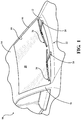
Figure 1 is a partial perspective view of a front of a vehicle having a pair of wiper assemblies pivotally mounted for reciprocal movement across a windshield of the vehicle. -
Figure 2 is an enlarged perspective view of a wiper assembly according to one embodiment of the present invention. -
Figure 3 is an exploded perspective view of the wiper assembly, according to one embodiment of the present invention, ofFigure 2 . -
Figure 4 is an enlarged sectional view of the wiper assembly taken along line 4-4 ofFigure 2 , according to one embodiment of the present invention, showing a support element, a wiping element, an airfoil, and an end cap. -
Figure 5 is an alternate sectional view of the wiper assembly ofFigure 4 , according to one embodiment of the present invention, showing a support element, a wiping element, and an airfoil. -
Figure 6 is an alternate sectional view of the airfoil ofFigures 4 and5 . - With reference to the Figures, where like numerals are used to designate like structure throughout the several views, a portion of a vehicle is schematically illustrated at 10 in
Figure 1 . Thevehicle 10 includes acowl 12, aroof 14, and a pair of laterally spacedfront A-pillars 16 extending between theroof 14 and thecowl 12. TheA-pillars 16,roof 14, andcowl 12 cooperate to define a generallyrectangular opening 18 in which a curved or "swept back"glass windshield 20 is supported. As illustrated, thevehicle 10 is an automobile, but could be any type of vehicle, such as a heavy-duty truck, train, airplane, ship, construction vehicle or equipment, military vehicle, or any other type of vehicle that contains surface wiper systems. - A wiper system is generally indicated at 22 in
Figure 1 and is employed to clean thewindshield 20. Thewiper system 22 includes a pair of wiper arms, generally indicated at 24, and a pair of wiper assemblies, generally indicated at 26, which correspond to the driver and passenger sides of thevehicle 10. However, those having ordinary skill in the art will appreciate that thewiper system 22 could employ asingle wiper arm 24 andsingle wiper assembly 26, or more than twowiper arms 24 and more than two wiper assemblies 26, without departing from the scope of the present invention. In the representative example illustrated herein, eachwiper assembly 26 is carried by acorresponding wiper arm 24. Thewiper system 22 also includes an electric motor (not shown, but generally known in the art) to move thewiper assemblies 26 in an oscillating manner across the surface of thewindshield 20. - While the
wiper assembly 26 illustrated inFigure 1 is shown in connection with thefront windshield 20 of thevehicle 10, those having ordinary skill in the art will appreciate thatwiper assemblies 26 could be used in other areas of thevehicle 10 that employ awiper system 22, such as a rear window (not shown) or a head lamp (not shown). Thus, it will be understood that the present invention is not limited for use solely in connection withwiper arms 24 adapted for use on a vehicle'swindshield 20, but for use in all applications wherewiper systems 22 are employed. - Referring to
Figures 2 and3 , thewiper assembly 26 includes awiping element 28 that is adapted to contact a surface of thevehicle 10 to be wiped, in this representative example, thewindshield 20. Thewiper assembly 26 also includes at least onesupport member 30 that defines a longitudinal axis and that acts to reinforce or support thewiping element 28. In the representative embodiment illustrated herein, thesupport member 30 is a monolithic beam mounted directly to thewiping element 28, as described in greater detail below. However, those having ordinary skill in the art will appreciate from the description that follows that thesupport member 30 could be either monolithic or defined by a pair of splines (not shown, but generally known in the art) without departing from the scope of the present invention. Thewiper assembly 26 also includes acoupler 32 operatively attached to thesupport member 30. Thecoupler 32 is configured to attach to anadapter 34 which, in turn, is adapted to connect to thewiper arm 24. Thewiper assembly 26 also includes an airfoil assembly, generally indicated at 36, to prevent thewiper assembly 26 from lifting away from the surface of thewindshield 20. Thewiper assembly 26 may still further include one or more end caps, generally indicated at 38, to prevent theairfoil assembly 26 from disengaging thesupport member 30. Each of the above components will be described in greater detail below. - The wiping
element 28 is configured to a predetermined length corresponding to a particular application, and is often manufactured through an extrusion process which enables the length of the wipingelement 28 to be easily adjusted without a substantial increase in manufacturing expense. Furthermore, while the wipingelement 28 of the present invention is constructed from a flexible rubber, those having ordinary skill in the art will appreciate that the wipingelement 28 could be constructed from any flexible material, such as silicone or another polymer, without departing from the scope of the present invention. Referring now toFigure 5 , the wipingelement 28 has a head portion, generally indicated at 40, a wipingportion 42 spaced from thehead portion 40, and a pair ofopposed grooves 44. Each of these components will be discussed in greater detail below. - The
head portion 40 of the wipingelement 28 is typically operatively attached to themonolithic support member 30 with an adhesive, such as glue (not shown, but generally known in the art). However, it will be appreciated that wipingelement 28 could be operatively attached to thesupport member 30 in any suitable way without departing from the scope of the present invention. - The wiping
portion 42 of the wipingelement 28 is adapted to contact the surface to be wiped 20. As shown inFigures 4 and5 , the wipingportion 42 has a generally triangular, tapered profile. However, those having ordinary skill in the art will appreciate that the wipingportion 42 could have any suitable profile, shape, or configuration without departing from the scope of the present invention. - The
grooves 44 of the wipingelement 28 are disposed between thehead portion 40 and the wipingportion 42. Thegrooves 44 face away from each other and are formed on opposite sides of the wipingelement 28. As shown best inFigure 5 , thegrooves 44 have a wedge-shaped profile. However, those having ordinary skill in the art will appreciate that thegrooves 44 could have any suitable profile and could be disposed in any suitable location along the wipingelement 28 between thehead portion 40 and the wipingportion 42, so as to cooperate with theairfoil 36, as described in greater detail below. As such, it will be appreciated from the description that follows that thegrooves 44 could be defined in or by other areas of the wipingelement 28 without departing from the scope of the present invention. - In one embodiment, as shown in
Figure 5 , the wipingelement 28 further includes amid portion 46 disposed between thehead portion 40 and the wipingportion 42, with thegrooves 44 being disposed between thehead portion 40 and themid portion 46. Those having ordinary skill in the art will appreciate that themid portion 46 could have any suitable profile or configuration, or be omitted from the wipingelement 28 without departing from the scope of the present invention. Further, in one embodiment, the wipingelement 28 includes abridge 48 disposed between themid portion 48 and the wipingportion 42. Thebridge 48 allows the wipingportion 42 to fold over in operation across thewindshield 20. However, those having ordinary skill in the art will appreciate that thebridge 48 could be disposed in any suitable part of the wipingelement 28. Specifically, as discussed above, it is conceivable that the wipingelement 28 could be designed without amid portion 46, wherein thebridge 48 would thus extend between thehead portion 40 and the wipingportion 42. As such, those having ordinary skill in the art will appreciate that thegrooves 44 could define thebridge 48 if the wipingelement 28 were designed without amid portion 46. Moreover, it will be appreciated that thebridge 48 could have any size, shape, or configuration suitable to allow the wipingportion 42 to fold over in operation without departing from the scope of the present invention. - As previously noted, the
wiper assembly 26 also includes at least onesupport member 30 extending between opposed longitudinal ends 50 (seeFigure 3 ). Thesupport member 30 is constructed from a resiliently flexible material, such as spring steel or a polymer, and is adapted to apply force from an intermediate position between the longitudinal ends 50. More specifically, thesupport member 30 receives force from the spring loadedwiper arm 24 at an intermediate position and distributes this force across the span of thesupport member 30 toward the longitudinal ends 50. To that end, thesupport member 30 may be curved longitudinally with a predetermined radius of curvature. In the related art, this predetermined radius of curvature is sometimes referred to as a "free form" radius of curvature. Accordingly, the curvature of thesupport member 30 may be symmetrical or asymmetrical, depending on the force requirements of the application and the contour of thewindshield 20. The flexible, free form,pre-curved support member 30 straightens out when thewiper arm 24 applies a force thereto and directs the wipingelement 28 to contact thewindshield 20. Thus, theelongated support member 30 includes a free-form curvature that ensures force distribution on windshields having various curvatures and that effects proper wrapping about thewindshield 20. - The
support member 30 may have a substantially constant width and a constant thickness throughout its length between the longitudinal ends 50. The constant width and thickness are adapted to provide high lateral and torsional stiffness so as to avoid lateral and torsional deflections, which cause the wipingelement 28 to stick/slip ("chatter") on thewindshield 20 during operation. Thus, the cross-section of thesupport member 30 has a generally rectangular outer profile that makes thesupport member 30 easier to manufacture. More specifically, where thesupport member 30 is constructed from metal, such as spring steel, the tools and machinery used to manufacture thesupport member 30 are less complicated than those required to manufacture asupport member 30 having varying width and/or thickness. Furthermore, where thesupport member 30 is constructed from a polymer, such as a thermoplastic elastomer, the manufacturing tools and extrusion process machinery are also less complicated than those employed to manufacture varying width and/or thicknesses. However, those having ordinary skill in the art will appreciate that thesupport member 30 could have a varying thickness and/or width without departing from the scope of the present invention. Further, as mentioned above, those having ordinary skill in the art will appreciate that thesupport member 30 could be monolithic or could be formed as a plurality of splines (sometimes referred to in the art as a "twin rail" blade). Thesupport member 30 may also include one or more notches (not shown, but generally known in the art) that cooperate with the end caps 38 to operatively attach the end caps 38 to the longitudinal ends 50 of thesupport member 30. Notches are generally rectangular, but those having ordinary skill in the art will appreciate that the notches could have any suitable shape, or could be omitted entirely, without departing from the scope of the present invention. Additionally, thesupport member 30 may include one or more securing features (not shown, but generally known in the art), such as additional notches, for cooperating with thecoupler 32 so as to operatively attach thesupport member 30 to thecoupler 32. Those having ordinary skill in the art will appreciate that securing features could be of any suitable shape or configuration, or could be omitted entirely, without departing from the scope of the present invention. Specifically, those having ordinary skill in the art will appreciate that thecoupler 32 could be fixed to thesupport member 30 in several different ways. By way of non-limiting example, thecoupler 32 could be glued, welded, crimped, bolted, riveted, formed-over, locked, or otherwise fixed to thesupport member 30, without departing from the scope of the present invention - The
wiper assembly 26 also typically includes acoupler 32 operatively attached to thesupport member 30. As illustrated inFigure 3 , thecoupler 32 has abase portion 54 and anaperture 56 disposed therein. Theaperture 56 is configured to releasably engage theadapter 44, as is discussed more thoroughly below. In the embodiment illustrated herein, thecoupler 32 is a unitary, one piece component. However, those having ordinary skill in the art will appreciate that thecoupler 32 could be designed as a plurality of components that interlock or otherwise cooperate to operatively attach to thesupport member 30, without departing from the scope of the present invention. Thecoupler 32 is typically constructed from plastic and is formed using an injection molding process. However, those having ordinary skill in the art will appreciate that thecoupler 32 could be constructed from any suitable material formed using any suitable process without departing from the scope of the present invention. - The
wiper assembly 26 also typically includes anadapter 34 operatively attached to thecoupler 32. Theadapter 34 is employed to releasably attach thewiper assembly 26 to one or more types ofwiper arms 24. Specifically, theadapter 34 illustrated inFigures 2 and3 includes locking features 58 that cooperate with theaperture 56 of thecoupler 32 to releasably attach theadapter 34 to thecoupler 32. However, those having ordinary skill in the art will appreciate that theadapter 34 could be operatively attached to thecoupler 32 in any suitable way without departing from the scope of the present invention. Further, those having ordinary skill in the art will appreciate that different OEM'semploy wiper arms 24 configured to releasably attach todifferent adapters 34 which are, in turn, operatively attached to aspecific wiper assembly 26. By way of example,certain wiper arms 24 employed by OEM's include "bayonet-style"; "pin-type"; "hook-type"; "push-button"; "pinch-tab"; or "side-pin" connection systems of various sizes. As such, it will be appreciated thatwiper arms 24 can be connected towiper assemblies 26 in a number of different ways, using different sizes and styles of connection systems. In the embodiment illustrated inFigures 2 and3 , theadapter 34 is mounted directly to thecoupler 32 and includes an internally-mountedpivoting connector 52 which is configured to attach to a wiper arm 24 (seeFigure 3 ). However, those having ordinary skill in the art will appreciate that theadapter 34 could be configured to connect directly to awiper arm 24 without aconnector 52. Specifically, it is conceivable that theadapter 34 could be pivotally mounted to thecoupler 32 and attach directly to awiper arm 24. - As illustrated in
Figures 2 and3 , in one embodiment, thewiper assembly 26 of the present invention also includes a pair ofend caps 38. The end caps 38 are adapted to be disposed adjacent to the distal ends of thesupport member 30. The end caps 38 are secured to thesupport member 30 and may have a profile that substantially mimics the contours of theairfoil assembly 36 so as to maintain the wind lift characteristics of thewiper assembly 26 and to provide an increased aesthetic value. The end caps 38 also provide a mass increase adjacent to the longitudinal ends 50 of thesupport member 30 that helps prevent localized chatter along the extremities of the wipingelement 28 caused by a combination of wind lift and a decrease in the force distributed from thewiper arm 24 via the support member, as described above. It should be appreciated that the end caps 38 may include a locking arm (not shown, but generally known in the art) or other features that engage notches (not shown, but generally known in the art) in thesupport member 30 so as to secure the end caps 38 to thesupport member 30, as discussed above. - The
wiper assembly 26 of the present invention also includes at least oneairfoil 36 operatively mounted to thesupport member 30. Theairfoil 36 extends along the length of thewiper assembly 26 and acts to reduce the likelihood of wind lift by allowing air to flow over thewiper assembly 26. More specifically, and in the embodiment illustrated herein, theairfoil 36 is formed as two individual components operatively mounted to thesupport member 30, with thecoupler 32 extending therebtween. However, those having ordinary skill in the art will appreciate that theairfoil 36 could be formed as any suitable number of individual components without departing from the scope of the present invention. - The
airfoil 36 is configured to a predetermined length corresponding to a particular application, and is often manufactured through an extrusion process which enables the length of theairfoil 36 to be easily adjusted without a substantial increase in manufacturing expense. However, those having ordinary skill in the art will appreciate that theairfoil 36 of the present invention could be constructed in other ways, such as by injection molding, without departing from the scope of the present invention. Furthermore, while theairfoil 36 of the present invention does not vary in size or shape along its length, it is conceivable that theairfoil 36 could be formed so as to taper or otherwise change in size or shape without departing from the scope of the present invention. Further still, while theairfoil 36 of the present invention is constructed from plastic, those having ordinary skill in the art will appreciate that theairfoil 36 could be constructed from any suitable material without departing from the scope of the present invention. Moreover, while theairfoil 36 of the present invention is extruded from a single material (seeFigure 6 ), those having ordinary skill in the art will appreciate that theairfoil 36 could be formed from a plurality of materials, such as by co-extrusion, over-molding, skin coating, etc., without departing from the scope of the present invention. - As shown best in
Figure 6 , theairfoil 36 has abody 60 with alower surface 62 and an outer profile, generally indicated at 64. In the embodiment illustrated herein, theouter profile 64 includes an upper surface 66 spaced from thelower surface 62, anattack surface 68 depending from the upper surface 66, aforward surface 70 connecting theattack surface 68 to thelower surface 62, arear surface 72 connecting thelower surface 62 to the upper surface 66, and a pair oflower protrusions 74 extending below thelower surface 62 and merging thelower surface 62 with each of theforward surface 70 andrear surface 72. Those having ordinary skill in the art will appreciate that theouter profile 64 described above defines an asymmetric spoiler-like body 60, wherein theattack surface 68 allows air to flow over theairfoil 36, which helps keep thewiper assembly 26 pressed against thewindshield 20 in operation. However, those having ordinary skill in the art will appreciate that thebody 60 of theairfoil 36 could have anouter profile 62 with any suitable shape without departing from the scope of the present invention. - As shown best in
Figure 6 , thebody 60 of theairfoil 36 also includes aslot 74 spaced from thelower surface 62. Theslot 74 is adapted to accommodate thesupport element 30, as described in greater detail below. Thebody 60 of theairfoil 36 also includes achannel 76 extending from thelower surface 62 to theslot 74. Thechannel 76 defines a pair ofopposed shelves 78 in thebody 60 of theairfoil 36. Theshelves 78 are spaced from each other so as to receive at least a part of thehead portion 40 of the wipingelement 28 therebetween. In this way, theslot 74 cooperates with thechannel 76 so as to receive thesupport element 30 and attached wipingelement 28 within thebody 60 of theairfoil 36. - Referring now to
Figures 5 and6 , thebody 60 of theairfoil 36 also includes a pair of concealingmembers 80 spaced from the slot 74 (seeFigures 4-6 ). As shown best inFigure 5 , the concealingmembers 80 of theairfoil 36 are at least partially disposed in thegrooves 44 of the wipingelement 28 such that thesupport element 30 is substantially concealed within thebody 60 of theairfoil 36 along the length of theairfoil 36. In one embodiment, the concealingmembers 80 depend from theshelves 78 partially into thechannel 76 and extend below thelower surface 62 of thebody 60 of the airfoil 36 (seeFigure 6 ). However, those having ordinary skill in the art will appreciate that the concealingmembers 80 could be disposed in any suitable location spaced from theslot 74, and could extend in any suitable way, without departing from the scope of the present invention. - As shown best in
Figure 6 , in one embodiment, the concealingmembers 80 have atop surface 82 and abottom surface 84 spaced from thetop surface 82. In the embodiment illustrated herein, thetop surface 82 is parallel to thebottom surface 84. However, those having ordinary skill in the art will appreciate that thetop surface 82 andbottom surface 84 could be configured, spaced, or shaped differently without departing from the scope of the present invention. Further, in one embodiment of the present invention, the concealingmembers 80 define anobtuse angle 86 between thelower surface 62 of thebody 60 of theairfoil 36 and at least one of thetop surface 82 andbottom surface 84 of the concealing members 80 (seeFigure 6 ). However, those having ordinary skill in the art will appreciate that the concealingmembers 80 could also be parallel with respect to thelower surface 62 of thebody 60 of theairfoil 36 without departing from the scope of the present invention. In the embodiment illustrated inFigures 4-6 , theobtuse angle 86 is approximately 160-degrees and is defined with respect to thetop surface 82 as well as thebottom surface 84. However, as discussed above, those having ordinary skill in the art will appreciate that thetop surface 82 andbottom surface 84 could be non-parallel and, thus, theobtuse angle 86 could be formed with only one of thetop surface 82 and thebottom surface 84 without departing from the scope of the present invention. - As shown in
Figure 5 , in one embodiment, the concealingmembers 80 have rounded ends 88 that are at least partially disposed in thegrooves 44 of the wipingelement 28. The rounded ends 88 help prevent the concealingmembers 80 from catching on, scratching, or tearing the wipingelement 28 during assembly and in operation. However, those having ordinary skill in the art will appreciate that the concealingmembers 80 could have ends configured differently without departing from the scope of the present invention. - Referring now to
Figure 5 , as discussed above, the wipingelement 28 cooperates with theairfoil 36 such that when thewiper assembly 26 is assembled, the concealingmembers 80 are disposed in thegrooves 44 of the wipingelement 28, thereby substantially concealing thesupport element 30 within thebody 60 of theairfoil 36. To this end, thegrooves 44 of the wipingelement 28 are spaced from each other and define afirst distance 90 therebetween. Similarly, asecond distance 92 is defined between the concealingmembers 80 of theairfoil 36. In one embodiment, thesecond distance 92 is greater than thefirst distance 90. Those having ordinary skill in the art will appreciate that thesecond distance 92 being greater than thefirst distance 90 prevents the concealingmembers 80 of theairfoil 36 from pinching the wipingelement 28, which is undesirable. Moreover, in one embodiment, athird distance 94 is defined by thehead portion 40 of the wipingelement 28, whereby thethird distance 94 is greater than thesecond distance 92. Those having ordinary skill in the art will appreciate that thethird distance 94 being greater than thesecond distance 92 ensures that thehead portion 40 of the wipingelement 28 is at least partially concealed by the concealingmembers 80, thereby ensuring that thesupport element 30 is substantially concealed. Further, those having ordinary skill in the art will appreciate that the spacing arrangements discussed above allow the concealingmembers 80 to be designed or formed in several different ways. Specifically, the concealingmembers 80 could be designed with any shape, size, or configuration suitable to be spaced from one another such that thesecond distance 92 is greater than thefirst distance 90, but smaller than thethird distance 94. Further, those having ordinary skill in the art will appreciate that the concealingmembers 80 could be designed asymmetrically and still maintain the spacing relationships discussed above without departing from the scope of the present invention. - In this way, the concealing
members 80 of the present invention improve performance of thewiper assembly 26 in winter driving conditions. Specifically, those having ordinary skill in the art will appreciate that the concealingmembers 80 help keep water, ice, and snow away from thesupport element 30, thereby substantially preventing accumulation of ice and snow, which could otherwise lead to a decrease in wiping performance or could cause thewiper assembly 26 to freeze to thewindshield 20. - The invention has been described in an illustrative manner. It is to be understood that the terminology which has been used is intended to be in the nature of words of description rather than of limitation. Many modifications and variations of the invention are possible in light of the above teachings. Therefore, within the scope of the appended claims, the invention may be practiced other than as specifically described.
Claims (11)
- A wiper assembly (26) comprising:at least one elongated support element (30);a wiping element (28) adapted to contact a surface to be wiped, the wiping element (28) having a head portion (40) operatively attached to the support element (30), a wiping portion (42) spaced from the head portion (40), and a pair of opposed grooves (44) disposed between the head portion (40) and the wiping portion (42); andan airfoil (36) having a body (60) with a lower surface (62), a slot (74) spaced from the lower surface (62) and accommodating the support element (30) therein, a channel (76) extending from the lower surface (62) to the slot (74) and defining a pair of opposed shelves (78), and a pair of concealing members (80) spaced from the slot (74) and at least partially disposed in the grooves (44) of the wiping element (28) to substantially conceal the support element (30) within the body (60) of the airfoil (36);characterized in thatthe concealing members (80) have a top surface (82) and a bottom surface (84) spaced from the top surface (82), where the concealing members (80) define an obtuse angle (86) between the lower surface (62) of the body (60) and at least one of the top surface (82) and the bottom surface (84) of the concealing members (80).
- The wiper assembly (26) as set forth in claim 1, wherein the concealing members (80) depend from the shelves (78).
- The wiper assembly (26) as set forth in claim 1, wherein the obtuse angle (86) is approximately 160 degrees.
- The wiper assembly (26) as set forth in claim 1, wherein the top surface (82) of the concealing members (80) is substantially parallel to the bottom surface (84) of the concealing members (80).
- The wiper assembly (26) as set forth in claim 1, wherein the concealing members (80) have rounded ends (88), with the ends (88) at least partially disposed in the grooves (44) of the wiping element (28).
- The wiper assembly (26) as set forth in claim 1, wherein a first distance (90) is defined between the grooves (44), a second distance (92) is defined between the concealing members (80), with the second distance (92) being greater than the first distance (90).
- The wiper assembly (26) as set forth in claim 6, wherein a third distance (94) is defined by the head portion (40) of the wiping element (28), with the third distance (94) being greater than the second distance (92).
- The wiper assembly (26) as set forth in claim 1, wherein the wiping element (28) further includes a mid portion (46) disposed between the head portion (40) and the wiping portion (42), with the grooves (44) disposed between the head portion (40) and the mid portion (46).
- The wiper assembly (26) as set forth in claim 8, wherein the wiping element (28) further includes a bridge (48) disposed between the mid portion (46) and the wiping portion (42) to allow the wiping portion (42) to fold over in operation.
- The wiper assembly (26) as set forth in any one of the preceding claims, further comprising a pair of end caps (38) operatively attached to the longitudinal ends (88) of the support element (30).
- The wiper assembly (26) as set forth in any one of the preceding claims, with the at least one airfoil (36) being operatively attached to the support element (30).
Applications Claiming Priority (2)
| Application Number | Priority Date | Filing Date | Title |
|---|---|---|---|
| US14/242,053 US20150274128A1 (en) | 2014-04-01 | 2014-04-01 | Winter wiper assembly |
| PCT/US2015/023571 WO2015153596A1 (en) | 2014-04-01 | 2015-03-31 | Winter wiper assembly |
Publications (3)
| Publication Number | Publication Date |
|---|---|
| EP3126197A1 EP3126197A1 (en) | 2017-02-08 |
| EP3126197A4 EP3126197A4 (en) | 2018-01-10 |
| EP3126197B1 true EP3126197B1 (en) | 2019-05-01 |
Family
ID=54189218
Family Applications (1)
| Application Number | Title | Priority Date | Filing Date |
|---|---|---|---|
| EP15772912.0A Active EP3126197B1 (en) | 2014-04-01 | 2015-03-31 | Winter wiper assembly |
Country Status (3)
| Country | Link |
|---|---|
| US (1) | US20150274128A1 (en) |
| EP (1) | EP3126197B1 (en) |
| WO (1) | WO2015153596A1 (en) |
Families Citing this family (3)
| Publication number | Priority date | Publication date | Assignee | Title |
|---|---|---|---|---|
| DE102014226365A1 (en) * | 2014-12-18 | 2016-06-23 | Robert Bosch Gmbh | Windshield wiper device |
| KR101691426B1 (en) * | 2015-04-17 | 2016-12-30 | 앨버리 프로덕츠 인코포레이티드 | Windshield wiper assembly |
| CN105480198A (en) * | 2015-12-21 | 2016-04-13 | 都昌县业达汽车零部件有限公司 | Wiper interchangeable multifunctional joint |
Family Cites Families (21)
| Publication number | Priority date | Publication date | Assignee | Title |
|---|---|---|---|---|
| GB1438568A (en) * | 1972-09-09 | 1976-06-09 | Fister Snc Di Bosso Giacomo C | Windshield wiper blade |
| GB1500219A (en) * | 1974-07-26 | 1978-02-08 | Rau Swf Autozubehoer | Wiper blade for wiper installations in vehicles |
| GB1513895A (en) * | 1974-08-22 | 1978-06-14 | Rau Swf Autozubehoer | Wiper blade for wiper installations in vehicles |
| DE10106874A1 (en) * | 2001-02-14 | 2002-09-05 | Volkswagen Ag | Wiper blade for vehicle windows |
| US7373688B2 (en) * | 2002-12-13 | 2008-05-20 | Asmo Co., Ltd. | Wiper blade provided with detachable blade rubber and wiper system having the same |
| FR2868747B1 (en) * | 2004-04-07 | 2008-06-20 | Valeo Systemes Dessuyage | FLAT-BLADE TYPE WIPER BLADE COMPRISING AERODYNAMIC DEFLECTOR |
| US20070017056A1 (en) * | 2005-07-19 | 2007-01-25 | Cooke Walter W | Wiper blade assembly and method of forming the same |
| US7861363B2 (en) * | 2006-02-02 | 2011-01-04 | Trico Products Corporation | Beam blade windshield wiper assembly having an airfoil |
| US20100064468A1 (en) * | 2006-12-07 | 2010-03-18 | Dong Hun Kang | Flat wiper blade for the vehicle |
| EP1964732A1 (en) * | 2007-02-27 | 2008-09-03 | Federal-Mogul S.A. | Windscreen wiper device |
| US8015656B2 (en) * | 2007-02-28 | 2011-09-13 | Mitsuba Corporation | Wiper blade |
| DE102007033594B4 (en) * | 2007-07-19 | 2020-08-06 | Volkswagen Ag | Wiper blade for a wiper |
| FR2923785B1 (en) * | 2007-11-19 | 2009-12-25 | Valeo Systemes Dessuyage | WIPER BLADE FOR VEHICLE WINDOWS. |
| US20090151111A1 (en) * | 2007-12-18 | 2009-06-18 | Chi-Hung Chang | Windshield wiper steel bar structure |
| MX2010011385A (en) * | 2008-04-15 | 2010-12-17 | Jamak Fabrication Tex Llc | Vehicle window wiper assembly. |
| DE102008041361A1 (en) * | 2008-08-20 | 2010-02-25 | Robert Bosch Gmbh | Wiper blade, particularly for wiping motor vehicle panes, has base part and wiping cloth part pivoted at base part, where base part has clamping shaped holding element |
| CN102112346B (en) * | 2008-09-04 | 2014-01-15 | 株式会社美姿把 | Wiper blade and vehicle wiper device |
| CN101857009B (en) * | 2009-04-13 | 2012-01-04 | 黄世贤 | Flat blade wiper |
| US8533899B2 (en) * | 2009-08-27 | 2013-09-17 | Trico Products Corporation | Windshield wiper assembly |
| US8495787B2 (en) * | 2010-08-03 | 2013-07-30 | Rally Manufacturing, Inc. | Windshield wiper |
| CN102991466B (en) * | 2011-09-15 | 2018-04-24 | 阿斯莫有限公司 | Windshield wiper blade and wiper for vehicle |
-
2014
- 2014-04-01 US US14/242,053 patent/US20150274128A1/en not_active Abandoned
-
2015
- 2015-03-31 WO PCT/US2015/023571 patent/WO2015153596A1/en active Application Filing
- 2015-03-31 EP EP15772912.0A patent/EP3126197B1/en active Active
Non-Patent Citations (1)
| Title |
|---|
| None * |
Also Published As
| Publication number | Publication date |
|---|---|
| US20150274128A1 (en) | 2015-10-01 |
| EP3126197A1 (en) | 2017-02-08 |
| EP3126197A4 (en) | 2018-01-10 |
| WO2015153596A1 (en) | 2015-10-08 |
Similar Documents
| Publication | Publication Date | Title |
|---|---|---|
| US7861363B2 (en) | Beam blade windshield wiper assembly having an airfoil | |
| EP2134576B1 (en) | Wiper assembly having side-saddle coupler | |
| US20150151718A1 (en) | Wiper coupler assembly and wiper assembly incorporating same | |
| CA2818258C (en) | Beam blade wiper assembly having self-locking end cap | |
| US10046739B2 (en) | Wiper adapter and wiper assembly incorporating the same | |
| EP3131796B1 (en) | Wiper adapter and wiper assembly incorporating the same | |
| EP3126197B1 (en) | Winter wiper assembly | |
| US9539987B2 (en) | Wiper adapter and wiper assembly incorporating the same | |
| US10071712B2 (en) | Wiper adapter and wiper assembly incorporating the same | |
| US9421951B2 (en) | Wiper assembly having an end cap | |
| US10391980B2 (en) | End cap for wiper assembly | |
| US9744945B2 (en) | End cap for retaining wiping element of wiper assembly | |
| US9663071B2 (en) | Wiper adapter and wiper assembly incorporating same | |
| US20150135466A1 (en) | Locking coupler for wiper assembly | |
| US11014539B2 (en) | Refillable wiper blade with refill subassembly | |
| US20150274129A1 (en) | Windshield wiper assembly having spline lock coupler | |
| US20140130285A1 (en) | Airfoil for wiper assembly | |
| US20140373298A1 (en) | Airfoil for hybrid wiper assembly | |
| US20150151715A1 (en) | Coupler assembly for wiper assembly |
Legal Events
| Date | Code | Title | Description |
|---|---|---|---|
| STAA | Information on the status of an ep patent application or granted ep patent |
Free format text: STATUS: THE INTERNATIONAL PUBLICATION HAS BEEN MADE |
|
| PUAI | Public reference made under article 153(3) epc to a published international application that has entered the european phase |
Free format text: ORIGINAL CODE: 0009012 |
|
| STAA | Information on the status of an ep patent application or granted ep patent |
Free format text: STATUS: REQUEST FOR EXAMINATION WAS MADE |
|
| 17P | Request for examination filed |
Effective date: 20161018 |
|
| AK | Designated contracting states |
Kind code of ref document: A1 Designated state(s): AL AT BE BG CH CY CZ DE DK EE ES FI FR GB GR HR HU IE IS IT LI LT LU LV MC MK MT NL NO PL PT RO RS SE SI SK SM TR |
|
| AX | Request for extension of the european patent |
Extension state: BA ME |
|
| DAV | Request for validation of the european patent (deleted) | ||
| DAX | Request for extension of the european patent (deleted) | ||
| A4 | Supplementary search report drawn up and despatched |
Effective date: 20171208 |
|
| RIC1 | Information provided on ipc code assigned before grant |
Ipc: B60S 1/38 20060101AFI20171204BHEP Ipc: B60S 1/40 20060101ALI20171204BHEP |
|
| GRAP | Despatch of communication of intention to grant a patent |
Free format text: ORIGINAL CODE: EPIDOSNIGR1 |
|
| STAA | Information on the status of an ep patent application or granted ep patent |
Free format text: STATUS: GRANT OF PATENT IS INTENDED |
|
| INTG | Intention to grant announced |
Effective date: 20181121 |
|
| GRAS | Grant fee paid |
Free format text: ORIGINAL CODE: EPIDOSNIGR3 |
|
| GRAA | (expected) grant |
Free format text: ORIGINAL CODE: 0009210 |
|
| STAA | Information on the status of an ep patent application or granted ep patent |
Free format text: STATUS: THE PATENT HAS BEEN GRANTED |
|
| AK | Designated contracting states |
Kind code of ref document: B1 Designated state(s): AL AT BE BG CH CY CZ DE DK EE ES FI FR GB GR HR HU IE IS IT LI LT LU LV MC MK MT NL NO PL PT RO RS SE SI SK SM TR |
|
| REG | Reference to a national code |
Ref country code: GB Ref legal event code: FG4D |
|
| REG | Reference to a national code |
Ref country code: CH Ref legal event code: EP Ref country code: AT Ref legal event code: REF Ref document number: 1126511 Country of ref document: AT Kind code of ref document: T Effective date: 20190515 |
|
| REG | Reference to a national code |
Ref country code: DE Ref legal event code: R096 Ref document number: 602015029389 Country of ref document: DE |
|
| REG | Reference to a national code |
Ref country code: IE Ref legal event code: FG4D |
|
| REG | Reference to a national code |
Ref country code: NL Ref legal event code: MP Effective date: 20190501 |
|
| REG | Reference to a national code |
Ref country code: LT Ref legal event code: MG4D |
|
| PG25 | Lapsed in a contracting state [announced via postgrant information from national office to epo] |
Ref country code: AL Free format text: LAPSE BECAUSE OF FAILURE TO SUBMIT A TRANSLATION OF THE DESCRIPTION OR TO PAY THE FEE WITHIN THE PRESCRIBED TIME-LIMIT Effective date: 20190501 Ref country code: PT Free format text: LAPSE BECAUSE OF FAILURE TO SUBMIT A TRANSLATION OF THE DESCRIPTION OR TO PAY THE FEE WITHIN THE PRESCRIBED TIME-LIMIT Effective date: 20190901 Ref country code: SE Free format text: LAPSE BECAUSE OF FAILURE TO SUBMIT A TRANSLATION OF THE DESCRIPTION OR TO PAY THE FEE WITHIN THE PRESCRIBED TIME-LIMIT Effective date: 20190501 Ref country code: FI Free format text: LAPSE BECAUSE OF FAILURE TO SUBMIT A TRANSLATION OF THE DESCRIPTION OR TO PAY THE FEE WITHIN THE PRESCRIBED TIME-LIMIT Effective date: 20190501 Ref country code: NO Free format text: LAPSE BECAUSE OF FAILURE TO SUBMIT A TRANSLATION OF THE DESCRIPTION OR TO PAY THE FEE WITHIN THE PRESCRIBED TIME-LIMIT Effective date: 20190801 Ref country code: NL Free format text: LAPSE BECAUSE OF FAILURE TO SUBMIT A TRANSLATION OF THE DESCRIPTION OR TO PAY THE FEE WITHIN THE PRESCRIBED TIME-LIMIT Effective date: 20190501 Ref country code: HR Free format text: LAPSE BECAUSE OF FAILURE TO SUBMIT A TRANSLATION OF THE DESCRIPTION OR TO PAY THE FEE WITHIN THE PRESCRIBED TIME-LIMIT Effective date: 20190501 Ref country code: LT Free format text: LAPSE BECAUSE OF FAILURE TO SUBMIT A TRANSLATION OF THE DESCRIPTION OR TO PAY THE FEE WITHIN THE PRESCRIBED TIME-LIMIT Effective date: 20190501 Ref country code: ES Free format text: LAPSE BECAUSE OF FAILURE TO SUBMIT A TRANSLATION OF THE DESCRIPTION OR TO PAY THE FEE WITHIN THE PRESCRIBED TIME-LIMIT Effective date: 20190501 |
|
| PG25 | Lapsed in a contracting state [announced via postgrant information from national office to epo] |
Ref country code: RS Free format text: LAPSE BECAUSE OF FAILURE TO SUBMIT A TRANSLATION OF THE DESCRIPTION OR TO PAY THE FEE WITHIN THE PRESCRIBED TIME-LIMIT Effective date: 20190501 Ref country code: BG Free format text: LAPSE BECAUSE OF FAILURE TO SUBMIT A TRANSLATION OF THE DESCRIPTION OR TO PAY THE FEE WITHIN THE PRESCRIBED TIME-LIMIT Effective date: 20190801 Ref country code: GR Free format text: LAPSE BECAUSE OF FAILURE TO SUBMIT A TRANSLATION OF THE DESCRIPTION OR TO PAY THE FEE WITHIN THE PRESCRIBED TIME-LIMIT Effective date: 20190802 Ref country code: LV Free format text: LAPSE BECAUSE OF FAILURE TO SUBMIT A TRANSLATION OF THE DESCRIPTION OR TO PAY THE FEE WITHIN THE PRESCRIBED TIME-LIMIT Effective date: 20190501 |
|
| REG | Reference to a national code |
Ref country code: AT Ref legal event code: MK05 Ref document number: 1126511 Country of ref document: AT Kind code of ref document: T Effective date: 20190501 |
|
| PG25 | Lapsed in a contracting state [announced via postgrant information from national office to epo] |
Ref country code: IS Free format text: LAPSE BECAUSE OF FAILURE TO SUBMIT A TRANSLATION OF THE DESCRIPTION OR TO PAY THE FEE WITHIN THE PRESCRIBED TIME-LIMIT Effective date: 20190901 |
|
| PG25 | Lapsed in a contracting state [announced via postgrant information from national office to epo] |
Ref country code: CZ Free format text: LAPSE BECAUSE OF FAILURE TO SUBMIT A TRANSLATION OF THE DESCRIPTION OR TO PAY THE FEE WITHIN THE PRESCRIBED TIME-LIMIT Effective date: 20190501 Ref country code: DK Free format text: LAPSE BECAUSE OF FAILURE TO SUBMIT A TRANSLATION OF THE DESCRIPTION OR TO PAY THE FEE WITHIN THE PRESCRIBED TIME-LIMIT Effective date: 20190501 Ref country code: RO Free format text: LAPSE BECAUSE OF FAILURE TO SUBMIT A TRANSLATION OF THE DESCRIPTION OR TO PAY THE FEE WITHIN THE PRESCRIBED TIME-LIMIT Effective date: 20190501 Ref country code: EE Free format text: LAPSE BECAUSE OF FAILURE TO SUBMIT A TRANSLATION OF THE DESCRIPTION OR TO PAY THE FEE WITHIN THE PRESCRIBED TIME-LIMIT Effective date: 20190501 Ref country code: AT Free format text: LAPSE BECAUSE OF FAILURE TO SUBMIT A TRANSLATION OF THE DESCRIPTION OR TO PAY THE FEE WITHIN THE PRESCRIBED TIME-LIMIT Effective date: 20190501 Ref country code: SK Free format text: LAPSE BECAUSE OF FAILURE TO SUBMIT A TRANSLATION OF THE DESCRIPTION OR TO PAY THE FEE WITHIN THE PRESCRIBED TIME-LIMIT Effective date: 20190501 |
|
| REG | Reference to a national code |
Ref country code: DE Ref legal event code: R097 Ref document number: 602015029389 Country of ref document: DE |
|
| PG25 | Lapsed in a contracting state [announced via postgrant information from national office to epo] |
Ref country code: IT Free format text: LAPSE BECAUSE OF FAILURE TO SUBMIT A TRANSLATION OF THE DESCRIPTION OR TO PAY THE FEE WITHIN THE PRESCRIBED TIME-LIMIT Effective date: 20190501 Ref country code: SM Free format text: LAPSE BECAUSE OF FAILURE TO SUBMIT A TRANSLATION OF THE DESCRIPTION OR TO PAY THE FEE WITHIN THE PRESCRIBED TIME-LIMIT Effective date: 20190501 |
|
| PLBE | No opposition filed within time limit |
Free format text: ORIGINAL CODE: 0009261 |
|
| STAA | Information on the status of an ep patent application or granted ep patent |
Free format text: STATUS: NO OPPOSITION FILED WITHIN TIME LIMIT |
|
| PG25 | Lapsed in a contracting state [announced via postgrant information from national office to epo] |
Ref country code: TR Free format text: LAPSE BECAUSE OF FAILURE TO SUBMIT A TRANSLATION OF THE DESCRIPTION OR TO PAY THE FEE WITHIN THE PRESCRIBED TIME-LIMIT Effective date: 20190501 |
|
| 26N | No opposition filed |
Effective date: 20200204 |
|
| PG25 | Lapsed in a contracting state [announced via postgrant information from national office to epo] |
Ref country code: PL Free format text: LAPSE BECAUSE OF FAILURE TO SUBMIT A TRANSLATION OF THE DESCRIPTION OR TO PAY THE FEE WITHIN THE PRESCRIBED TIME-LIMIT Effective date: 20190501 |
|
| PG25 | Lapsed in a contracting state [announced via postgrant information from national office to epo] |
Ref country code: SI Free format text: LAPSE BECAUSE OF FAILURE TO SUBMIT A TRANSLATION OF THE DESCRIPTION OR TO PAY THE FEE WITHIN THE PRESCRIBED TIME-LIMIT Effective date: 20190501 |
|
| PG25 | Lapsed in a contracting state [announced via postgrant information from national office to epo] |
Ref country code: MC Free format text: LAPSE BECAUSE OF FAILURE TO SUBMIT A TRANSLATION OF THE DESCRIPTION OR TO PAY THE FEE WITHIN THE PRESCRIBED TIME-LIMIT Effective date: 20190501 |
|
| REG | Reference to a national code |
Ref country code: CH Ref legal event code: PL |
|
| REG | Reference to a national code |
Ref country code: BE Ref legal event code: MM Effective date: 20200331 |
|
| PG25 | Lapsed in a contracting state [announced via postgrant information from national office to epo] |
Ref country code: LU Free format text: LAPSE BECAUSE OF NON-PAYMENT OF DUE FEES Effective date: 20200331 |
|
| PG25 | Lapsed in a contracting state [announced via postgrant information from national office to epo] |
Ref country code: IE Free format text: LAPSE BECAUSE OF NON-PAYMENT OF DUE FEES Effective date: 20200331 Ref country code: LI Free format text: LAPSE BECAUSE OF NON-PAYMENT OF DUE FEES Effective date: 20200331 Ref country code: CH Free format text: LAPSE BECAUSE OF NON-PAYMENT OF DUE FEES Effective date: 20200331 |
|
| PG25 | Lapsed in a contracting state [announced via postgrant information from national office to epo] |
Ref country code: BE Free format text: LAPSE BECAUSE OF NON-PAYMENT OF DUE FEES Effective date: 20200331 |
|
| PG25 | Lapsed in a contracting state [announced via postgrant information from national office to epo] |
Ref country code: MT Free format text: LAPSE BECAUSE OF FAILURE TO SUBMIT A TRANSLATION OF THE DESCRIPTION OR TO PAY THE FEE WITHIN THE PRESCRIBED TIME-LIMIT Effective date: 20190501 Ref country code: CY Free format text: LAPSE BECAUSE OF FAILURE TO SUBMIT A TRANSLATION OF THE DESCRIPTION OR TO PAY THE FEE WITHIN THE PRESCRIBED TIME-LIMIT Effective date: 20190501 |
|
| PG25 | Lapsed in a contracting state [announced via postgrant information from national office to epo] |
Ref country code: MK Free format text: LAPSE BECAUSE OF FAILURE TO SUBMIT A TRANSLATION OF THE DESCRIPTION OR TO PAY THE FEE WITHIN THE PRESCRIBED TIME-LIMIT Effective date: 20190501 |
|
| PGFP | Annual fee paid to national office [announced via postgrant information from national office to epo] |
Ref country code: FR Payment date: 20230327 Year of fee payment: 9 |
|
| PGFP | Annual fee paid to national office [announced via postgrant information from national office to epo] |
Ref country code: GB Payment date: 20230327 Year of fee payment: 9 Ref country code: DE Payment date: 20230329 Year of fee payment: 9 |
|
| P01 | Opt-out of the competence of the unified patent court (upc) registered |
Effective date: 20230529 |