EP3126040B1 - Method for scale-up of spray dried inhalation powders - Google Patents
Method for scale-up of spray dried inhalation powders Download PDFInfo
- Publication number
- EP3126040B1 EP3126040B1 EP15715803.1A EP15715803A EP3126040B1 EP 3126040 B1 EP3126040 B1 EP 3126040B1 EP 15715803 A EP15715803 A EP 15715803A EP 3126040 B1 EP3126040 B1 EP 3126040B1
- Authority
- EP
- European Patent Office
- Prior art keywords
- spray dryer
- gas flow
- flow rate
- nozzles
- drying gas
- Prior art date
- Legal status (The legal status is an assumption and is not a legal conclusion. Google has not performed a legal analysis and makes no representation as to the accuracy of the status listed.)
- Active
Links
Images



Classifications
-
- B—PERFORMING OPERATIONS; TRANSPORTING
- B01—PHYSICAL OR CHEMICAL PROCESSES OR APPARATUS IN GENERAL
- B01J—CHEMICAL OR PHYSICAL PROCESSES, e.g. CATALYSIS OR COLLOID CHEMISTRY; THEIR RELEVANT APPARATUS
- B01J2/00—Processes or devices for granulating materials, e.g. fertilisers in general; Rendering particulate materials free flowing in general, e.g. making them hydrophobic
- B01J2/02—Processes or devices for granulating materials, e.g. fertilisers in general; Rendering particulate materials free flowing in general, e.g. making them hydrophobic by dividing the liquid material into drops, e.g. by spraying, and solidifying the drops
- B01J2/04—Processes or devices for granulating materials, e.g. fertilisers in general; Rendering particulate materials free flowing in general, e.g. making them hydrophobic by dividing the liquid material into drops, e.g. by spraying, and solidifying the drops in a gaseous medium
-
- A—HUMAN NECESSITIES
- A61—MEDICAL OR VETERINARY SCIENCE; HYGIENE
- A61K—PREPARATIONS FOR MEDICAL, DENTAL OR TOILETRY PURPOSES
- A61K9/00—Medicinal preparations characterised by special physical form
- A61K9/14—Particulate form, e.g. powders, Processes for size reducing of pure drugs or the resulting products, Pure drug nanoparticles
- A61K9/16—Agglomerates; Granulates; Microbeadlets ; Microspheres; Pellets; Solid products obtained by spray drying, spray freeze drying, spray congealing,(multiple) emulsion solvent evaporation or extraction
- A61K9/1682—Processes
-
- B—PERFORMING OPERATIONS; TRANSPORTING
- B01—PHYSICAL OR CHEMICAL PROCESSES OR APPARATUS IN GENERAL
- B01D—SEPARATION
- B01D1/00—Evaporating
- B01D1/16—Evaporating by spraying
- B01D1/18—Evaporating by spraying to obtain dry solids
Definitions
- the present invention is in the technical field of drying methods. More particularly, the present invention is in the technical field of spray drying applied particularly, but not exclusively, to active pharmaceutical ingredients (APIs), drug product intermediates and drug products intended for inhalation delivery.
- active pharmaceutical ingredients (APIs), drug product intermediates and drug products may be organic compounds.
- WO 03/090893 discloses a process that uses a multi-nozzle apparatus to promote powder agglomeration with negligible product deposits on the walls, through reintroduction of the fines near the main spray plume.
- a paper by Turton et al. [ Turton, R; Cheng, X. "The scale-up of spray coating processes for granular solids and tablets”; Powder Technology 150 (2005) 78-85 ] discloses a spray coating process for granular solids and tablets that makes use of multiple nozzles to cover a wider area.
- US 8524279 discloses a process mostly intended for inhalation products that report the use of a multi-nozzle atomizer comprised of a central gas nozzle and a plurality of atomization nozzles around such central gas nozzle.
- the central gas nozzle is used to minimize spray plume interactions and to control the final powder characteristics, while the feed mixture is atomized in the atomization nozzles.
- the invention herein disclosed overcomes the shortcomings identified in the prior art, by using multiple low throughput off-the-shelf nozzles.
- the ratio between liquid and atomization gas flow rate can be maintained as constant in each nozzle across spray dryer scales, which leads to similar sized droplets across scales and eliminates the challenges faced during scale-up that were previously described.
- This enables a direct scale-up of the process since the operating conditions used in the smaller scale can be directly used in a larger scale spray dryer as each nozzle is geometrically the same across scales. In this way, the single scale-up action to be conducted will be to increase the number of nozzles to be used proportionally to the scale of the spray drying unit.
- the idea herein disclosed comprises two innovative concepts that overcome the limitations found in the art and expedites process development:
- a method for scaling-up a spray drying process for preparing particles for inhalation from a smaller scale spray dryer to a larger scale spray dryer, relative in size to each other comprising the use in the larger scale spray dryer of a multi-nozzle apparatus comprising single nozzles suitable for use in preparing inhalation powders, wherein the smaller scale spray dryer comprises a number m of nozzles and the larger scale spray dryer comprises a number n of nozzles, wherein n is determined by the ratio, rounded up or down to a whole number, of the drying gas flow rate of the larger scale spray dryer to the drying gas flow rate of the smaller scale spray dryer; spray angles for each of the n nozzles are arranged such that, in use, no significant spray overlapping will occur; and all the single nozzles are of the same type.
- the drying gas flow rate may be known as a nominal drying gas flow rate.
- a spray dryer for use in preparing particles for inhalation comprising a multi-nozzle apparatus comprising multiple single nozzles suitable for use in preparing inhalation powders, wherein the drying gas flow rate of the spray dryer is greater than about 80 kg/h.
- a multi-nozzle apparatus for use in a spray dryer is also disclosed herein, said multi-nozzle apparatus produced from the method of the present invention, wherein the multi-nozzle apparatus comprises multiple single nozzles suitable for use in preparing inhalation powders.
- the nozzles suitable for use in preparing particles for inhalation may be suitable for use in preparing particles for inhalation comprising active pharmaceutical ingredients, drug product intermediates or drug products, optionally organic active pharmaceutical ingredients, drug product intermediates or drug products.
- the particles for inhalation may have a mean particle size less than about 5 microns, preferably less than about 3 microns
- n is equal to the ratio of the drying gas flow rate of the larger scale spray dryer to the drying gas flow rate of the smaller scale spray dryer rounded up or down to a whole number.
- the drying gas flow rate of the smaller scale spray dryer may be from about 20 kg/h to about 120 kg/h, preferably from about 40 kg/h to about 80 kg/h, most preferably about 40 kg/h.
- the drying gas flow rate of the larger spray dryer may be larger than about 80 kg/h.
- the drying gas flow rate of the spray dryer may be greater than about 120 kg/h or greater than about 150 kg/h.
- the drying gas flow rate of the spray dryer may be about 360 kg/h, about 650 kg/h or about 1250 kg/h.
- the single nozzles used in the method of the present invention and the apparatus disclosed herein may be two-fluid external or internal mixture nozzles preferably two-fluid external mixture nozzles.
- the liquid feed flow and atomization gas flow may be homogeneously distributed amongst the n single nozzles.
- All nozzles are of the same type, and they can be chosen from any off-the-shelf commercially available nozzles typically used on spray dryers of small sizes (for example Size 1 (SD1), to which a nominal drying gas flow rate of approximately 80 kg/h corresponds).
- SD1 Size 1
- small spray dryer or “small scale spray dryer” we mean spray dryers intended to be typically used in a laboratory setting or at pilot scale, having a typical nominal gas flow rate of 20 to 120 kg/h preferably of 40 to 80 kg/h.
- spray dryers include but are not limited to BUCHI model B-290, with a typical nominal gas flow rate of about 20 to 40 kg/h, Niro Mobile Minor, with a typical nominal gas flow rate of about 40 to 120 kg/h, and Anhydro Spray Drying of SPX, with a typical nominal gas flow rate of about 35 to 150 kg/h.
- large spray dryer we mean spray dryers intended to be used in an industrial setting (even if the units are small production units) having typical nominal flow gas rate of > 80 kg/h.
- spray dryers include but are not limited to Niro spray dryers of size 2, 3 and 4 having typical nominal gas flow rate of about 360, 650 and 1250 kg/h (or upgraded units of size 1, prepared to handle larger drying gas flow rates) and Anhydro Spray Drying of SPX, with a typical nominal gas flow rate of about 400 to 2500 kg/h.
- the number of single nozzles used in the larger scale spray dryer is determined by the ratio of the drying gas flow rate of the larger scale spray dryer to the drying gas flow rate of the smaller scale spray dryer.
- an apparatus with dimensions that enable the positioning of n single nozzles within the spray drying chambers, and that are the same as or similar to the dimensions of conventional off-the-shelf atomization systems, thereby avoiding expensive retrofitting of spray dryers or complex assembly procedures that are prone to human error - see Figure 1 and Figure 2 .
- the apparatus disclosed herein may be used in an existing manufacturing plant in place of an existing atomization system.
- the distribution of the liquid feed flow and atomization gas flow should be homogeneous amongst the n single nozzles as illustrated in Figure 1 due to the symmetrical geometry of the apparatus. This enables a set of identical sprays and ensures droplet size is the same from one single nozzle to the other, and hence does not impact the final particle size distribution of the obtained powder.
- the shape, size and positioning of the apparatus do not significantly impact the drying gas flow pattern within the spray drying chambers as shown in Figure 3 , which avoids any disruption to gas distribution and all the typical operational problems that derive from such.
- the spray angles for each single nozzle are arranged such that no significant spray overlapping will occur (which could lead to droplet coalescence and, consequently, particle size increase) - see Figure 4 .
- the spray angles for each single nozzle can be arranged such that spray penetration will not cause the impact of droplets (nor of wet particles) on the walls of the equipment (which could lead to yield losses and product degradation).
- Figure 5 also shows that the spray shape need not be impacted, thus avoiding the phenomena of secondary atomization (which could lead to droplet coalescence and break-up, with consequent impact on final particle size).
- other configurations of nozzles could readily be designed by the skilled person. For example the skilled person could arrange a set of four nozzles to direct spray in four different directions from a single point or could design two sets of two nozzles to direct spray in two different directions from two different points.
- the advantages of the present invention include, without limitation, the simplification (to a great extent) of the scale-up of spray dried inhalation powders since no development (or minimal development) will be involved, as operating conditions from the smaller scale can be maintained approximately constant. Essentially, the single scale-up action required will be to increase the number of nozzles used.
- An additional benefit of the present invention is that it may be used as an enabling technology since, when moving to larger scale spray dryers (for example SD2 or larger), no scale-up methodologies are currently available in the art for inhalation powders. Similarly, no suitable nozzles are known for inhalation powders, since nozzle manufactures make no assurances of hitting the target particle size, reducing the applicability of the current technology.
- a feed mixture was prepared by dissolving 1.2 g of lysine and 4.8 g of trehalose in 234 g of water (total solids concentration approximately 2.5% w/w).
- This excipient system is known to yield amorphous powders, where particle size is more sensitive to variations of the atomization conditions. Therefore, this excipient system is ideal for the current proof-of-concept.
- a laboratory scale spray dryer (BUCHI model B-290 Advanced) was used to process the above mentioned feed solution.
- the BUCHI unit was equipped with a single two-fluid nozzle where nozzle cap and diameter were 1.4 and 0.7 mm, respectively.
- the BUCHI unit was equipped with a duo of two-fluid nozzles ( Figure 6 ), each one with a nozzle cap and diameter of 1.4 and 0.7 mm (that is, identical to the nozzle of Trial #1).
- the flowrate of solution fed to the single nozzle was approximately 3 g/min and the flowrate of atomization gas fed to the single nozzle was approximately 9 g/min (equivalent to 30 mm in the rotameter).
- the flowrate of solution fed to the apparatus was 6 g/min and the flowrate of atomization gas fed to the apparatus as approximately 20 g/min (equivalent to 60 mm in the rotameter).
- a feed mixture was prepared by dissolving 1.225 kg of leucine and 4.9 kg of trehalose in 33.8 kg of ethanol and in 135.1 kg of water (total solids concentration approximately 3.5% w/w).
- a SD1 operating at a nominal drying gas flow rate of approximately 110 kg/h, was used to process the above mentioned feed solution.
- the flowrate of solution fed to the two nozzles of the multi-nozzle atomizer was approximately 2 kg/h and the flowrate of atomization gas fed to the apparatus was approximately 20 kg/h.
- the flowrate of solution fed to the single nozzle of the multi-nozzle atomizer was 1 kg/h and the flowrate of atomization gas fed to the apparatus was approximately 10 kg/h.
- a feed mixture was prepared by dissolving 1.225 kg of leucine and 4.9 kg of trehalose in 33.8 kg of ethanol and in 135.1 kg of water (total solids concentration approximately 3.5% w/w).
- a SD2 operating at a nominal drying gas flow rate of approximately 360 kg/h, was used to process the above mentioned feed solution.
Landscapes
- Chemical & Material Sciences (AREA)
- Chemical Kinetics & Catalysis (AREA)
- Health & Medical Sciences (AREA)
- Organic Chemistry (AREA)
- Engineering & Computer Science (AREA)
- Bioinformatics & Cheminformatics (AREA)
- Epidemiology (AREA)
- Pharmacology & Pharmacy (AREA)
- Medicinal Chemistry (AREA)
- Life Sciences & Earth Sciences (AREA)
- Animal Behavior & Ethology (AREA)
- General Health & Medical Sciences (AREA)
- Public Health (AREA)
- Veterinary Medicine (AREA)
- Medicinal Preparation (AREA)
- Glanulating (AREA)
- Vaporization, Distillation, Condensation, Sublimation, And Cold Traps (AREA)
- Nozzles (AREA)
Description
- The present invention is in the technical field of drying methods. More particularly, the present invention is in the technical field of spray drying applied particularly, but not exclusively, to active pharmaceutical ingredients (APIs), drug product intermediates and drug products intended for inhalation delivery. The active pharmaceutical ingredients (APIs), drug product intermediates and drug products may be organic compounds.
- The development of manufacturing processes for spray dried inhalation powders involves two challenging constraints: i) a very small particle size is required (with a mean diameter below 5 microns, typically below 3 microns); and ii) the particle size should not be allowed to increase during scale-up (despite the fact that the majority of powders spray dried for oral dosage delivery will tend to increase in particle size during scale-up). These constraints pose important challenges during development, as current off-the-shelf atomization systems lose efficiency when having to manage an increase in throughput upon scale-up. Such loss of efficiency makes necessary the use of a larger quantity of gas for atomization, which leads to distinct challenges depending on the type of atomization system used:
- a) In the case of two-fluid external mixture nozzles (high consumers of atomization gas at low pressures), the flow rate of atomization gas may increase to such an extent that the drying chamber size and the rest of the process train may become under-dimensioned for the process (as the atomization gas flow rate requirement can increase, theoretically, to a demand of 30-50% of the total gas flow rate in the spray dryer).
- b) For two-fluid internal mixture nozzles (low consumers of atomization gas at high pressures), an increase of atomization gas flow rate may promote such an increase in pressure drop in the nozzle that the pressure of the gas feed lines may often require very complex and expensive upgrades.
- While such challenges might be overcome through engineering upgrades to the spray dryer process train, there remains an even more difficult challenge to address, since there is still the potential for the droplet size to be outside the intended range upon scale-up. It is not uncommon that the nozzle being applied at the smaller scale cannot be directly applied at the larger scale as its operating ranges are exceeded. Additionally, selecting a new nozzle is typically complex, time-consuming and expensive as extensive testing is required. Furthermore, there are no guarantees that such process development activities lead to a successful identification of an adequate candidate nozzle, as there are physical limitations to atomize large flow rates of liquid into small droplets within the target inhalation range. Hence, the current approach to controlling particle size within the inhalation range upon scale-up is limited by nozzle design (external or internal mixture, and nozzle model) and atomization gas flow rate. A different option for controlling particle size would be to decrease solids concentration in the feed mixture, but this is not a recommended approach as it negatively affects the process throughput and cycle time, and ultimately its feasibility from a process economics perspective.
- The concept of using multi-nozzle atomization for combining high feed capacity with fine atomization for both pressure nozzles and two-fluid nozzles is known in the art [Green, D; Perry, R. "Perry's chemical engineers' handbook" (2008)]. The spray drying literature includes additional examples where multi-nozzle arrangements were used. For example,
US 2002/0007869 discloses a multi-nozzle electrospraying method for the production of nanoparticles with high mass throughput. -
WO 03/090893 - In
US 2007/0148325 a granulation method is disclosed for the production of fine aqueous particles using the necessary number of nozzles equivalent to those of conventional design. - A paper by Turton et al. [Turton, R; Cheng, X. "The scale-up of spray coating processes for granular solids and tablets"; Powder Technology 150 (2005) 78-85] discloses a spray coating process for granular solids and tablets that makes use of multiple nozzles to cover a wider area.
-
US 8524279 discloses a process mostly intended for inhalation products that report the use of a multi-nozzle atomizer comprised of a central gas nozzle and a plurality of atomization nozzles around such central gas nozzle. The central gas nozzle is used to minimize spray plume interactions and to control the final powder characteristics, while the feed mixture is atomized in the atomization nozzles. - Whilst such examples mostly disclose multi-nozzle systems targeted for an increase in process throughput, and in some cases enabling the production of particles in the inhalable range, there remains a need in inhalation spray drying for a simple means of controlling particle size upon scale-up. The invention herein disclosed overcomes the shortcomings identified in the prior art, by using multiple low throughput off-the-shelf nozzles. The ratio between liquid and atomization gas flow rate can be maintained as constant in each nozzle across spray dryer scales, which leads to similar sized droplets across scales and eliminates the challenges faced during scale-up that were previously described. This enables a direct scale-up of the process since the operating conditions used in the smaller scale can be directly used in a larger scale spray dryer as each nozzle is geometrically the same across scales. In this way, the single scale-up action to be conducted will be to increase the number of nozzles to be used proportionally to the scale of the spray drying unit. Hence, the idea herein disclosed comprises two innovative concepts that overcome the limitations found in the art and expedites process development:
- 1) The ability to generate particles in the inhalable range (that is, characterized by a volumetric distribution with a mean geometric size below 5 microns), regardless of the required throughput; the high-throughput multi-nozzle systems that can be currently found in the art do not disclose such critical performance criterion, and
- 2) Meeting the target particle size range with the use of the same nozzle regardless of the scale (only the number of nozzles is being changed, not the model and type). The multi-nozzle systems that can be currently found available consider different variations / models when throughput is required to be increased above certain ranges.
- Hence, the conventional pharmaceutical spray drying methods used in the production of inhalation powders are limited in terms of fulfillment of critical quality attributes (namely in what concerns the particle size distribution) when higher throughputs are required; the proposed concept is expected to overcome this limitation and, additionally, to expedite process development.
- According to an aspect of the present invention, there is provided a method for scaling-up a spray drying process for preparing particles for inhalation from a smaller scale spray dryer to a larger scale spray dryer, relative in size to each other, said method comprising the use in the larger scale spray dryer of a multi-nozzle apparatus comprising single nozzles suitable for use in preparing inhalation powders, wherein the smaller scale spray dryer comprises a number m of nozzles and the larger scale spray dryer comprises a number n of nozzles, wherein n is determined by the ratio, rounded up or down to a whole number, of the drying gas flow rate of the larger scale spray dryer to the drying gas flow rate of the smaller scale spray dryer; spray angles for each of the n nozzles are arranged such that, in use, no significant spray overlapping will occur; and all the single nozzles are of the same type. The drying gas flow rate may be known as a nominal drying gas flow rate.
- A spray dryer for use in preparing particles for inhalation is disclosed herein, said spray dryer comprising a multi-nozzle apparatus comprising multiple single nozzles suitable for use in preparing inhalation powders, wherein the drying gas flow rate of the spray dryer is greater than about 80 kg/h.
- A multi-nozzle apparatus for use in a spray dryer is also disclosed herein, said multi-nozzle apparatus produced from the method of the present invention, wherein the multi-nozzle apparatus comprises multiple single nozzles suitable for use in preparing inhalation powders.
- The use of multiple single nozzles suitable for use in preparing inhalation powders in a spray dryer is also disclosed herein, wherein the drying gas flow rate of the spray dryer is greater than about 80 kg/h.
- The nozzles suitable for use in preparing particles for inhalation may be suitable for use in preparing particles for inhalation comprising active pharmaceutical ingredients, drug product intermediates or drug products, optionally organic active pharmaceutical ingredients, drug product intermediates or drug products. The particles for inhalation may have a mean particle size less than about 5 microns, preferably less than about 3 microns
- In the method of the present invention, n is equal to the ratio of the drying gas flow rate of the larger scale spray dryer to the drying gas flow rate of the smaller scale spray dryer rounded up or down to a whole number. Furthermore, in the method of the present invention, m may be between 1 and 4, optionally m = 1 or 2 or 3, and n may be between 2 and 16, preferably n= 2 or 3 or 4 or 5 or 8 or 10 or 16. In fact, the number of single nozzles used in the spray dryer, multi-nozzle apparatus and use disclosed herein may also be between 2 and 16, preferably n= 2 or 3 or 4 or 5 or 8 or 10 or 16.
- The drying gas flow rate of the smaller scale spray dryer may be from about 20 kg/h to about 120 kg/h, preferably from about 40 kg/h to about 80 kg/h, most preferably about 40 kg/h. The drying gas flow rate of the larger spray dryer may be larger than about 80 kg/h. Optionally, the drying gas flow rate of the spray dryer may be greater than about 120 kg/h or greater than about 150 kg/h. The drying gas flow rate of the spray dryer may be about 360 kg/h, about 650 kg/h or about 1250 kg/h.
- The single nozzles used in the method of the present invention and the apparatus disclosed herein may be two-fluid external or internal mixture nozzles preferably two-fluid external mixture nozzles. The liquid feed flow and atomization gas flow may be homogeneously distributed amongst the n single nozzles.
- In some embodiments of the method of the present invention, the drying gas flow rate of the smaller scale spray dryer is about 80 kg/h and the drying gas flow rate of the larger spray dryer is about 360 kg/h and m = 1 and n = 4. Alternatively, the drying gas flow rate of the larger spray dryer is about 650 kg/h and m = 1 and n = 8.
- An innovative concept is disclosed herein where multiple nozzles are simultaneously used. All nozzles are of the same type, and they can be chosen from any off-the-shelf commercially available nozzles typically used on spray dryers of small sizes (for example Size 1 (SD1), to which a nominal drying gas flow rate of approximately 80 kg/h corresponds). This assures that the particle size distribution obtained by a single specific nozzle at the SD1 scale is the same obtained by a scaled-up spray dryer at larger scales (for example size 2 (SD2) or size 3 (SD3) scales to which a nominal drying gas flow rate of for example approximately 360 kg/h or approximately 650 kg/h of drying gas flow, corresponds respectively), without significant development work (that is, without requiring the type of nozzle to be changed and just via an increase in the number of nozzles used).
- By "small spray dryer" or "small scale spray dryer" we mean spray dryers intended to be typically used in a laboratory setting or at pilot scale, having a typical nominal gas flow rate of 20 to 120 kg/h preferably of 40 to 80 kg/h. Examples of such spray dryers include but are not limited to BUCHI model B-290, with a typical nominal gas flow rate of about 20 to 40 kg/h, Niro Mobile Minor, with a typical nominal gas flow rate of about 40 to 120 kg/h, and Anhydro Spray Drying of SPX, with a typical nominal gas flow rate of about 35 to 150 kg/h.
- By "large spray dryer" we mean spray dryers intended to be used in an industrial setting (even if the units are small production units) having typical nominal flow gas rate of > 80 kg/h. Examples of such spray dryers include but are not limited to Niro spray dryers of
size size 1, prepared to handle larger drying gas flow rates) and Anhydro Spray Drying of SPX, with a typical nominal gas flow rate of about 400 to 2500 kg/h. -
-
Fig. 1 is a representation of the multi-nozzle atomizer meant for a SD2 scale spray dryer (external view and view of the liquid circuit). -
Fig. 2 is a side view illustration of the spray plumes of the multi-nozzle atomizer in a SD2 scale spray dryer. -
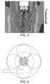
Fig. 3 shows results of a Computational Fluid Dynamics (CFD) simulation close to the nozzle. -
Fig. 4 is a top view illustration of the spray plumes of the multi-nozzle atomizer in a SD2 scale spray dryer. -
Fig. 5 shows results of a Computational Fluid Dynamics (CFD) simulation over the drying chamber. -
Fig. 6 shows the multi-nozzle system used in the laboratory experiments:- 1 - Solution feed
- 2 - Gas feed
-
Fig. 7 and8 show optical microscopy images of the particles obtained in the laboratory experiments. -
Fig. 9 shows scanning electron microscope images of the particles obtained in the SD1 unit experiments (left side - multi-nozzle atomizer operating with 2 nozzles and right side - multi-nozzle atomizer operating with 1 nozzle). -
Fig. 10 shows the particle size distribution of the particles obtained in the SD1 unit experiments (left side - multi-nozzle atomizer operating with 2 nozzles and right side - multi-nozzle atomizer operating with 1 nozzle). -
Fig. 11 shows scanning electron microscope images of the particles obtained in the commercial scale spray dryer experiment. - Referring now in more detail to the method of the present invention, and the spray dryer, apparatus and use disclosed herein , all of which use multiple single nozzles of the type used in a smaller scale spray dryer for use in preparing inhalation powders in order to match the drying gas flow rate of a larger spray dryer. For example, for a single nozzle typical of a spray dryer (SD1) with a gas flow rate of approximately 80 kg/
h 4 nozzles may be used for a spray dryer (SD2) with approximately 360 kg/h of drying gas, or 8 nozzles may be used for a spray dryer (SD3) with approximately 650 kg/h of drying gas -Figure 1 shows a possible configuration of the resulting apparatus for the larger SD2 scale. - This means that the number of single nozzles used in the larger scale spray dryer is determined by the ratio of the drying gas flow rate of the larger scale spray dryer to the drying gas flow rate of the smaller scale spray dryer.
- In more detail, an apparatus with dimensions that enable the positioning of n single nozzles within the spray drying chambers, and that are the same as or similar to the dimensions of conventional off-the-shelf atomization systems, thereby avoiding expensive retrofitting of spray dryers or complex assembly procedures that are prone to human error - see
Figure 1 and Figure 2 . Hence the apparatus disclosed herein may be used in an existing manufacturing plant in place of an existing atomization system. - The distribution of the liquid feed flow and atomization gas flow should be homogeneous amongst the n single nozzles as illustrated in
Figure 1 due to the symmetrical geometry of the apparatus. This enables a set of identical sprays and ensures droplet size is the same from one single nozzle to the other, and hence does not impact the final particle size distribution of the obtained powder. - The shape, size and positioning of the apparatus do not significantly impact the drying gas flow pattern within the spray drying chambers as shown in
Figure 3 , which avoids any disruption to gas distribution and all the typical operational problems that derive from such. Moreover, the spray angles for each single nozzle (relative to each other) are arranged such that no significant spray overlapping will occur (which could lead to droplet coalescence and, consequently, particle size increase) - seeFigure 4 . As shown inFigure 5 , the spray angles for each single nozzle (relative to the chamber) can be arranged such that spray penetration will not cause the impact of droplets (nor of wet particles) on the walls of the equipment (which could lead to yield losses and product degradation).Figure 5 also shows that the spray shape need not be impacted, thus avoiding the phenomena of secondary atomization (which could lead to droplet coalescence and break-up, with consequent impact on final particle size). Furthermore, other configurations of nozzles could readily be designed by the skilled person. For example the skilled person could arrange a set of four nozzles to direct spray in four different directions from a single point or could design two sets of two nozzles to direct spray in two different directions from two different points. - The advantages of the present invention include, without limitation, the simplification (to a great extent) of the scale-up of spray dried inhalation powders since no development (or minimal development) will be involved, as operating conditions from the smaller scale can be maintained approximately constant. Essentially, the single scale-up action required will be to increase the number of nozzles used. An additional benefit of the present invention is that it may be used as an enabling technology since, when moving to larger scale spray dryers (for example SD2 or larger), no scale-up methodologies are currently available in the art for inhalation powders. Similarly, no suitable nozzles are known for inhalation powders, since nozzle manufactures make no assurances of hitting the target particle size, reducing the applicability of the current technology.
- In order that the invention may be more fully understood, the following examples are included by way of illustration only.
- This example demonstrates the proof-of-concept, by considering a scaled-down version (shown in
Figure 6 ) of the invention. - A feed mixture was prepared by dissolving 1.2 g of lysine and 4.8 g of trehalose in 234 g of water (total solids concentration approximately 2.5% w/w). This excipient system is known to yield amorphous powders, where particle size is more sensitive to variations of the atomization conditions. Therefore, this excipient system is ideal for the current proof-of-concept.
- A laboratory scale spray dryer (BUCHI model B-290 Advanced) was used to process the above mentioned feed solution. In
Trial # 1, the BUCHI unit was equipped with a single two-fluid nozzle where nozzle cap and diameter were 1.4 and 0.7 mm, respectively. InTrial # 2, the BUCHI unit was equipped with a duo of two-fluid nozzles (Figure 6 ), each one with a nozzle cap and diameter of 1.4 and 0.7 mm (that is, identical to the nozzle of Trial #1). - During the first trial, the flowrate of solution fed to the single nozzle was approximately 3 g/min and the flowrate of atomization gas fed to the single nozzle was approximately 9 g/min (equivalent to 30 mm in the rotameter).
- During the second trial, the flowrate of solution fed to the apparatus (duo of nozzles) was 6 g/min and the flowrate of atomization gas fed to the apparatus as approximately 20 g/min (equivalent to 60 mm in the rotameter).
- Based on the above conditions, each nozzle (independently of the trial) was being used under similar atomization conditions (atomization ratio = F_atomiz / F_feed approximately 3).
- The thermal profile imposed in both tests (that it, the relationship between T_in and T_out) was similar (since significantly different thermal profiles may impact particle formation); the small differences derive from the fact that, in
Trial # 2, twice the solvent was being evaporated at the same drying gas flowrate, therefore requiring a slightly higher inlet temperature (in order to fulfill the thermodynamic balance).Trial Single 2-fluid nozzle Duo of 2-fluid nozzles F_drying kg/h approx. 40 approx. 40 F_feed g/min approx.. 3 approx.3 (in each) R_atomiz approx. 3 approx.3 (in each) T_in °C 141 160 T_out °C 95 95 Yield % w/w 86 87 Note: F_drying - drying gas flowrate; F_feed - solution flowrate; R_atomiz - atomization ratio; T_in - inlet drying temperature; T_out - outlet drying temperature. - As can be seen in
Figures 7 (Single nozzle) and 8 (Duo of nozzles), the particle size distribution and morphology is identical when comparing the powders obtained via the "Single nozzle" and the "Duo of nozzles", demonstrating the success of the current proof-of-concept and, in this way, the feasibility of a multi-nozzle concept, capable of fulfilling all the previous aims and goals. - This example demonstrates the proof-of-concept, by considering a multi-nozzle atomizer (shown in
Figure 1 ) of the invention employed in a SD1 unit. - A feed mixture was prepared by dissolving 1.225 kg of leucine and 4.9 kg of trehalose in 33.8 kg of ethanol and in 135.1 kg of water (total solids concentration approximately 3.5% w/w).
- A SD1, operating at a nominal drying gas flow rate of approximately 110 kg/h, was used to process the above mentioned feed solution. In
Trial # 1, the SD1 unit was equipped with a multi-nozzle atomizer operating with 2 NIRO ETFN (orifice = 0.5 mm) and a special housing for homogeneous liquid and gas distribution. InTrial # 2, the SD1 unit was equipped with the multi-nozzle atomizer operating with 1 NIRO ETFN (orifice = 0.5 mm). - During the first trial, the flowrate of solution fed to the two nozzles of the multi-nozzle atomizer was approximately 2 kg/h and the flowrate of atomization gas fed to the apparatus was approximately 20 kg/h.
- During the second trial, the flowrate of solution fed to the single nozzle of the multi-nozzle atomizer was 1 kg/h and the flowrate of atomization gas fed to the apparatus was approximately 10 kg/h.
- Based on the above conditions, each nozzle (independently of the trial) was being used under similar atomization conditions (atomization ratio = F_atomiz / F_feed approximately 10).
- The thermal profile imposed in both tests (that is, the relationship between T_in and T_out) presented differences that derive from the fact that, in
Trial # 1, twice the solvent was being evaporated at the same drying gas flowrate, therefore requiring a higher inlet temperature (in order to fulfill the thermodynamic balance).Trial Multi-nozzle operating with 2 nozzle Multi-nozzle operating with 1 nozzle F_drying kg/h approx. 110 approx. 110 F_feed kg/h approx. 2 approx. 1 R_atomiz approx. 10 approx. 10 T_in °C 151 127 T_out ° C 80 80 Yield % w/w 68 64 - As can be seen in
Figures 9 and10 the morphology and particle size distribution is identical when comparing the powders, demonstrating the success of the current proof-of-concept and, in this way, the feasibility of a multi-nozzle concept, capable of fulfilling all the previous aims and goals. - This example demonstrates the proof-of-concept, by considering a multi-nozzle atomizer (shown in
Figure 1 ) of the invention employed in a commercial scale spray dryer unit. - A feed mixture was prepared by dissolving 1.225 kg of leucine and 4.9 kg of trehalose in 33.8 kg of ethanol and in 135.1 kg of water (total solids concentration approximately 3.5% w/w).
- A SD2, operating at a nominal drying gas flow rate of approximately 360 kg/h, was used to process the above mentioned feed solution. The SD2 unit was equipped with a multi-nozzle atomizer operating with 4 NIRO ETFN (orifice = 0.5 mm) and a special housing for homogeneous liquid and gas distribution.
- During the trial, the flowrate of solution fed to the multi-nozzle atomizer was approximately 8 kg/h and the flowrate of atomization gas fed to the apparatus was approximately 20 kg/h.
Trial Multi-nozzle operating with 4 nozzles F_drying kg/h approx. 360 F_feed kg/h approx. 8 R_atomiz approx. 2.5 T_in °C 134 T_out °C 95 Yield % w/w 93 - As can be seen in
Figure 11 (Multi-nozzle atomizer operating with 4 nozzles), the particle size distribution and morphology is identical to the powders generated in Example 2, demonstrating the success of the current proof-of-concept and, in this way, the feasibility of a multi-nozzle concept, capable of fulfilling all the previous aims and goals. - While the foregoing written description of the invention enables one of ordinary skill to make and use what is considered presently to be the best mode thereof, those of ordinary skill will understand and appreciate the existence of variations, combinations, and equivalents of the specific embodiment, method, and examples herein. The invention should therefore not be limited by the above described embodiment, method, and examples, but by all embodiments and methods within the scope of the invention as claimed.
Claims (12)
- A method for scaling-up a spray drying process for preparing particles for inhalation from a smaller scale spray dryer to a larger scale spray dryer, relative in size to each other, said method comprising the use in the larger scale spray dryer of a multi-nozzle apparatus comprising single nozzles suitable for use in preparing inhalation powders, in which the smaller scale spray dryer comprises a number m of nozzles and the larger scale spray dryer comprises a number n of nozzles, whereinn is determined by the ratio, rounded up or down to a whole number, of the drying gas flow rate of the larger scale spray dryer to the drying gas flow rate of the smaller scale spray dryer;spray angles for each of the n nozzles are arranged such that, in use, no significant spray overlapping will occur; andall the single nozzles are of the same type.
- A method according to claim 1 wherein the ratio of the drying gas flow rate of the larger scale spray dryer to the drying gas flow rate of the smaller scale spray dryer is rounded down to a whole number.
- A method according to claim 1 or 2 wherein the drying gas flow rate of the smaller scale spray dryer is from about 20 kg/h to about 120 kg/h, optionally from about 40 kg/h to about 80 kg/h, more optionally about 40 kg/h.
- A method according to claim 1, 2 or 3 wherein the drying gas flow rate of the larger spray dryer is greater than about 80 kg/h, greater than about 120 kg/h, or greater than 150 kg/h.
- A method according to any of claims 1 to 4 wherein the drying gas flow rate of the larger spray dryer is about 360 kg/h, about 650 kg/h, or about 1250 kg/h.
- A method according to any of claims 1 to 5 wherein m is between 1 and 4, optionally m = 1 or 2 or 3.
- A method according to any of claims 1 to 6 wherein n is between 2 and 16, optionally n= 2 or 3 or 4 or 5 or 8 or 10 or 16.
- A method according to any of claims 1 to 7 wherein the drying gas flow rate of the smaller scale spray dryer is about 80 kg/h and the drying gas flow rate of the larger spray dryer is about 360 kg/h and m = 1 and n = 4 or the drying gas flow rate of the larger spray dryer is about 650 kg/h and m = 1 and n = 8.
- A method according to any of claims 1 to 8 wherein the particles for inhalation comprise active pharmaceutical ingredients, drug product intermediates or drug products, optionally organic active pharmaceutical ingredients, drug product intermediates or drug products.
- A method according to any of claims 1 to 9 wherein the particles have a mean particle size less than about 5 microns, optionally less than about 3 microns.
- A method according to any of claims 1 to 10 wherein the single nozzles are two-fluid external or internal mixture nozzles optionally two-fluid external mixture nozzles.
- A method according to any of claims 1 to 11, wherein the liquid feed flow and atomization gas flow are homogeneously distributed amongst the single nozzles.
Applications Claiming Priority (2)
| Application Number | Priority Date | Filing Date | Title |
|---|---|---|---|
| PT10756714A PT107567B (en) | 2014-03-31 | 2014-03-31 | ATOMIZATION DRYER WITH MULTIPLE ATOMIZER, METHOD FOR INCREASING DRIAL POWDER SCALE BY MULTIPLE ATOMIZATION DEVICE AND USE OF VARIOUS ATOMIZERS IN ONE ATOMIZATION DRYER |
| PCT/GB2015/050960 WO2015150761A1 (en) | 2014-03-31 | 2015-03-30 | Multi-nozzle spray dryer, method for scale-up of spray dried inhalation powders, multi-nozzle apparatus and use of multiple nozzles in a spray dryer |
Publications (3)
| Publication Number | Publication Date |
|---|---|
| EP3126040A1 EP3126040A1 (en) | 2017-02-08 |
| EP3126040C0 EP3126040C0 (en) | 2024-08-07 |
| EP3126040B1 true EP3126040B1 (en) | 2024-08-07 |
Family
ID=52824497
Family Applications (1)
| Application Number | Title | Priority Date | Filing Date |
|---|---|---|---|
| EP15715803.1A Active EP3126040B1 (en) | 2014-03-31 | 2015-03-30 | Method for scale-up of spray dried inhalation powders |
Country Status (10)
| Country | Link |
|---|---|
| US (1) | US10369537B2 (en) |
| EP (1) | EP3126040B1 (en) |
| JP (1) | JP6585076B2 (en) |
| CN (2) | CN115487744B (en) |
| AU (1) | AU2015242442B2 (en) |
| CA (1) | CA2944345C (en) |
| ES (1) | ES2988480T3 (en) |
| IL (1) | IL248162B (en) |
| PT (1) | PT107567B (en) |
| WO (1) | WO2015150761A1 (en) |
Families Citing this family (3)
| Publication number | Priority date | Publication date | Assignee | Title |
|---|---|---|---|---|
| PT107567B (en) | 2014-03-31 | 2019-02-13 | Hovione Farm S A | ATOMIZATION DRYER WITH MULTIPLE ATOMIZER, METHOD FOR INCREASING DRIAL POWDER SCALE BY MULTIPLE ATOMIZATION DEVICE AND USE OF VARIOUS ATOMIZERS IN ONE ATOMIZATION DRYER |
| US20190039189A1 (en) * | 2017-08-03 | 2019-02-07 | Honeywell International Inc. | Free flowing potassium aluminum fluoride flux agent |
| JP7410952B2 (en) | 2018-12-21 | 2024-01-10 | ノヴォ ノルディスク アー/エス | Process of spray drying of GLP-1 peptide |
Family Cites Families (22)
| Publication number | Priority date | Publication date | Assignee | Title |
|---|---|---|---|---|
| FR1495427A (en) * | 1966-03-02 | 1967-09-22 | Progil | Method and apparatus for granulating fluid products |
| US6223455B1 (en) * | 1999-05-03 | 2001-05-01 | Acusphere, Inc. | Spray drying apparatus and methods of use |
| DE19927537A1 (en) * | 1999-06-16 | 2000-12-21 | Merck Patent Gmbh | Spray drying plant and method of using it |
| AU780327B2 (en) * | 1999-06-30 | 2005-03-17 | Novartis Ag | Spray drying process for preparing dry powders |
| US8771740B2 (en) * | 1999-12-20 | 2014-07-08 | Nicholas J. Kerkhof | Process for producing nanoparticles by spray drying |
| US6764720B2 (en) | 2000-05-16 | 2004-07-20 | Regents Of The University Of Minnesota | High mass throughput particle generation using multiple nozzle spraying |
| TW200300696A (en) * | 2001-11-01 | 2003-06-16 | Inhale Therapeutic Syst | Spray drying methods and related compositions |
| KR100664822B1 (en) * | 2002-02-01 | 2007-01-04 | 화이자 프로덕츠 인코포레이티드 | Process for preparing homogeneous spray-dried solid amorphous drug dispersions using a modified spray-drying apparatus |
| US7008644B2 (en) * | 2002-03-20 | 2006-03-07 | Advanced Inhalation Research, Inc. | Method and apparatus for producing dry particles |
| NL1020469C2 (en) | 2002-04-25 | 2003-10-28 | Carlisle Process Systems B V | Spray drying device and feed means for such a spray drying device. |
| US6962006B2 (en) * | 2002-12-19 | 2005-11-08 | Acusphere, Inc. | Methods and apparatus for making particles using spray dryer and in-line jet mill |
| CN100395036C (en) * | 2003-01-22 | 2008-06-18 | 孙泰炎 | Dual Fluid Nozzle |
| US20050013869A1 (en) * | 2003-07-18 | 2005-01-20 | Chaw Cheng Shu | Sustained release formulation for carbamates and a method therefor |
| CN1714922A (en) * | 2004-07-02 | 2006-01-04 | 刘岷汀 | Microwave spray drier |
| CN101027494A (en) * | 2004-07-29 | 2007-08-29 | 推进动力公司 | Jet pump |
| RU2008100237A (en) * | 2005-06-14 | 2009-07-20 | Джилид Сайэнс, Инк. (US) | GENERAL MEDICINAL FORMS OF STEROIDS AND β-AGONISTS (OPTIONS), INCLUDING THEIR AEROSOL COMPOSITION (OPTIONS) AND METHOD FOR PREVENTING AND / OR TREATING PULMONARY INFLAMMATION AND / OR IMPLEMENTING |
| JP4589225B2 (en) | 2005-12-22 | 2010-12-01 | 東洋エンジニアリング株式会社 | Granule product manufacturing method |
| PT105058B (en) * | 2010-04-21 | 2013-04-17 | Hovione Farmaciencia S A | PROCESS FOR PROCESSING OF PARTICLES OF PHARMACEUTICAL ACTIVE INGREDIENTS |
| CN102069045B (en) * | 2010-12-03 | 2012-09-26 | 中国船舶重工集团公司第七一○研究所 | Unpowered rotatable cavitation jet nozzle |
| WO2012116697A1 (en) * | 2011-02-28 | 2012-09-07 | Gea Process Engineering A/S | External mixing pressurized two-fluid nozzle and a spray drying method |
| WO2012163082A1 (en) * | 2011-05-27 | 2012-12-06 | Zhang Yuliang | Jet exhaust energy-saving method during thermodynamic process |
| PT107567B (en) | 2014-03-31 | 2019-02-13 | Hovione Farm S A | ATOMIZATION DRYER WITH MULTIPLE ATOMIZER, METHOD FOR INCREASING DRIAL POWDER SCALE BY MULTIPLE ATOMIZATION DEVICE AND USE OF VARIOUS ATOMIZERS IN ONE ATOMIZATION DRYER |
-
2014
- 2014-03-31 PT PT10756714A patent/PT107567B/en active IP Right Grant
-
2015
- 2015-03-30 CN CN202210876138.2A patent/CN115487744B/en active Active
- 2015-03-30 EP EP15715803.1A patent/EP3126040B1/en active Active
- 2015-03-30 IL IL248162A patent/IL248162B/en unknown
- 2015-03-30 CN CN201580023072.0A patent/CN106457181A/en active Pending
- 2015-03-30 AU AU2015242442A patent/AU2015242442B2/en active Active
- 2015-03-30 ES ES15715803T patent/ES2988480T3/en active Active
- 2015-03-30 WO PCT/GB2015/050960 patent/WO2015150761A1/en not_active Ceased
- 2015-03-30 JP JP2016560498A patent/JP6585076B2/en active Active
- 2015-03-30 CA CA2944345A patent/CA2944345C/en active Active
-
2016
- 2016-09-29 US US15/280,433 patent/US10369537B2/en active Active
Also Published As
| Publication number | Publication date |
|---|---|
| CN115487744A (en) | 2022-12-20 |
| ES2988480T3 (en) | 2024-11-20 |
| PT107567A (en) | 2015-09-30 |
| CN115487744B (en) | 2025-10-28 |
| EP3126040C0 (en) | 2024-08-07 |
| CN106457181A (en) | 2017-02-22 |
| PT107567B (en) | 2019-02-13 |
| US20170014789A1 (en) | 2017-01-19 |
| JP6585076B2 (en) | 2019-10-02 |
| IL248162B (en) | 2022-07-01 |
| CA2944345A1 (en) | 2015-10-08 |
| CA2944345C (en) | 2022-06-14 |
| JP2017512644A (en) | 2017-05-25 |
| AU2015242442A1 (en) | 2016-10-20 |
| IL248162A0 (en) | 2016-11-30 |
| US10369537B2 (en) | 2019-08-06 |
| AU2015242442B2 (en) | 2019-03-28 |
| WO2015150761A1 (en) | 2015-10-08 |
| EP3126040A1 (en) | 2017-02-08 |
Similar Documents
| Publication | Publication Date | Title |
|---|---|---|
| Kumar et al. | Particle size reduction techniques of pharmaceutical compounds for the enhancement of their dissolution rate and bioavailability | |
| JP5850544B2 (en) | Spray dryer | |
| Long et al. | From batch to continuous—New opportunities for supercritical CO2 technology in pharmaceutical manufacturing | |
| Shariati et al. | Recent developments in particle design using supercritical fluids | |
| Reverchon et al. | Pilot scale micronization of amoxicillin by supercritical antisolvent precipitation | |
| JP6025706B2 (en) | Method and apparatus for generating microparticles or nanoparticles | |
| US6931888B2 (en) | Lyophilization method and apparatus for producing particles | |
| US10369537B2 (en) | Multi-nozzle spray dryer, method for scale-up of spray dried inhalation powders, multi-nozzle apparatus and use of multiple nozzles in a spray dryer | |
| Dehghani et al. | Dense gas anti-solvent processes for pharmaceutical formulation | |
| CN109225059A (en) | Fluid unit for coating solid particles | |
| KR20110118714A (en) | Method for preparing pharmaceutical drug particles of small particle size | |
| Pusapati et al. | Fluidized bed processing: A review | |
| CN203886208U (en) | Spray drying equipment for pesticide micro-capsule solid preparation | |
| WO2004110603A2 (en) | Method for preparation of particles from solution-in-supercritical fluid or compressed gas emulsions | |
| Aundhia et al. | Spray Drying in the pharmaceuticaul Industry-A Review | |
| JP3155028B2 (en) | Spray drying granulator | |
| JP2017512644A5 (en) | ||
| CN111954520A (en) | Spray drying method for continuous preparation of spray solutions | |
| CN101230021B (en) | Process for the preparation of urea granules | |
| Reverchon et al. | Beclomethasone microparticles for wet inhalation, produced by supercritical assisted atomization | |
| Kale et al. | Recent advancements in particle engi-neering techniques for pharmaceutical applications | |
| US12357956B2 (en) | Particle coating method | |
| US20030150085A1 (en) | Manipulation of solvent properties for particle formation | |
| Jaskulski et al. | CFD model-supported design of monodisperse co-current spray dryers | |
| Gemci et al. | SPRAY CHARACTERIZATION FOR FLUIDIZED BED GRANULATION PROCESSES |
Legal Events
| Date | Code | Title | Description |
|---|---|---|---|
| STAA | Information on the status of an ep patent application or granted ep patent |
Free format text: STATUS: THE INTERNATIONAL PUBLICATION HAS BEEN MADE |
|
| PUAI | Public reference made under article 153(3) epc to a published international application that has entered the european phase |
Free format text: ORIGINAL CODE: 0009012 |
|
| STAA | Information on the status of an ep patent application or granted ep patent |
Free format text: STATUS: REQUEST FOR EXAMINATION WAS MADE |
|
| 17P | Request for examination filed |
Effective date: 20161031 |
|
| AK | Designated contracting states |
Kind code of ref document: A1 Designated state(s): AL AT BE BG CH CY CZ DE DK EE ES FI FR GB GR HR HU IE IS IT LI LT LU LV MC MK MT NL NO PL PT RO RS SE SI SK SM TR |
|
| AX | Request for extension of the european patent |
Extension state: BA ME |
|
| DAV | Request for validation of the european patent (deleted) | ||
| DAX | Request for extension of the european patent (deleted) | ||
| STAA | Information on the status of an ep patent application or granted ep patent |
Free format text: STATUS: EXAMINATION IS IN PROGRESS |
|
| 17Q | First examination report despatched |
Effective date: 20190627 |
|
| GRAP | Despatch of communication of intention to grant a patent |
Free format text: ORIGINAL CODE: EPIDOSNIGR1 |
|
| STAA | Information on the status of an ep patent application or granted ep patent |
Free format text: STATUS: GRANT OF PATENT IS INTENDED |
|
| INTG | Intention to grant announced |
Effective date: 20240226 |
|
| GRAS | Grant fee paid |
Free format text: ORIGINAL CODE: EPIDOSNIGR3 |
|
| GRAA | (expected) grant |
Free format text: ORIGINAL CODE: 0009210 |
|
| STAA | Information on the status of an ep patent application or granted ep patent |
Free format text: STATUS: THE PATENT HAS BEEN GRANTED |
|
| AK | Designated contracting states |
Kind code of ref document: B1 Designated state(s): AL AT BE BG CH CY CZ DE DK EE ES FI FR GB GR HR HU IE IS IT LI LT LU LV MC MK MT NL NO PL PT RO RS SE SI SK SM TR |
|
| REG | Reference to a national code |
Ref country code: GB Ref legal event code: FG4D |
|
| REG | Reference to a national code |
Ref country code: CH Ref legal event code: EP |
|
| REG | Reference to a national code |
Ref country code: IE Ref legal event code: FG4D |
|
| REG | Reference to a national code |
Ref country code: DE Ref legal event code: R096 Ref document number: 602015089436 Country of ref document: DE |
|
| U01 | Request for unitary effect filed |
Effective date: 20240906 |
|
| U07 | Unitary effect registered |
Designated state(s): AT BE BG DE DK EE FI FR IT LT LU LV MT NL PT RO SE SI Effective date: 20240920 |
|
| REG | Reference to a national code |
Ref country code: ES Ref legal event code: FG2A Ref document number: 2988480 Country of ref document: ES Kind code of ref document: T3 Effective date: 20241120 |
|
| PG25 | Lapsed in a contracting state [announced via postgrant information from national office to epo] |
Ref country code: NO Free format text: LAPSE BECAUSE OF FAILURE TO SUBMIT A TRANSLATION OF THE DESCRIPTION OR TO PAY THE FEE WITHIN THE PRESCRIBED TIME-LIMIT Effective date: 20241107 |
|
| PG25 | Lapsed in a contracting state [announced via postgrant information from national office to epo] |
Ref country code: PL Free format text: LAPSE BECAUSE OF FAILURE TO SUBMIT A TRANSLATION OF THE DESCRIPTION OR TO PAY THE FEE WITHIN THE PRESCRIBED TIME-LIMIT Effective date: 20240807 Ref country code: GR Free format text: LAPSE BECAUSE OF FAILURE TO SUBMIT A TRANSLATION OF THE DESCRIPTION OR TO PAY THE FEE WITHIN THE PRESCRIBED TIME-LIMIT Effective date: 20241108 |
|
| PG25 | Lapsed in a contracting state [announced via postgrant information from national office to epo] |
Ref country code: IS Free format text: LAPSE BECAUSE OF FAILURE TO SUBMIT A TRANSLATION OF THE DESCRIPTION OR TO PAY THE FEE WITHIN THE PRESCRIBED TIME-LIMIT Effective date: 20241207 |
|
| PG25 | Lapsed in a contracting state [announced via postgrant information from national office to epo] |
Ref country code: HR Free format text: LAPSE BECAUSE OF FAILURE TO SUBMIT A TRANSLATION OF THE DESCRIPTION OR TO PAY THE FEE WITHIN THE PRESCRIBED TIME-LIMIT Effective date: 20240807 |
|
| PG25 | Lapsed in a contracting state [announced via postgrant information from national office to epo] |
Ref country code: RS Free format text: LAPSE BECAUSE OF FAILURE TO SUBMIT A TRANSLATION OF THE DESCRIPTION OR TO PAY THE FEE WITHIN THE PRESCRIBED TIME-LIMIT Effective date: 20241107 |
|
| PG25 | Lapsed in a contracting state [announced via postgrant information from national office to epo] |
Ref country code: RS Free format text: LAPSE BECAUSE OF FAILURE TO SUBMIT A TRANSLATION OF THE DESCRIPTION OR TO PAY THE FEE WITHIN THE PRESCRIBED TIME-LIMIT Effective date: 20241107 Ref country code: PL Free format text: LAPSE BECAUSE OF FAILURE TO SUBMIT A TRANSLATION OF THE DESCRIPTION OR TO PAY THE FEE WITHIN THE PRESCRIBED TIME-LIMIT Effective date: 20240807 Ref country code: NO Free format text: LAPSE BECAUSE OF FAILURE TO SUBMIT A TRANSLATION OF THE DESCRIPTION OR TO PAY THE FEE WITHIN THE PRESCRIBED TIME-LIMIT Effective date: 20241107 Ref country code: IS Free format text: LAPSE BECAUSE OF FAILURE TO SUBMIT A TRANSLATION OF THE DESCRIPTION OR TO PAY THE FEE WITHIN THE PRESCRIBED TIME-LIMIT Effective date: 20241207 Ref country code: HR Free format text: LAPSE BECAUSE OF FAILURE TO SUBMIT A TRANSLATION OF THE DESCRIPTION OR TO PAY THE FEE WITHIN THE PRESCRIBED TIME-LIMIT Effective date: 20240807 Ref country code: GR Free format text: LAPSE BECAUSE OF FAILURE TO SUBMIT A TRANSLATION OF THE DESCRIPTION OR TO PAY THE FEE WITHIN THE PRESCRIBED TIME-LIMIT Effective date: 20241108 |
|
| U20 | Renewal fee for the european patent with unitary effect paid |
Year of fee payment: 11 Effective date: 20250210 |
|
| PG25 | Lapsed in a contracting state [announced via postgrant information from national office to epo] |
Ref country code: SM Free format text: LAPSE BECAUSE OF FAILURE TO SUBMIT A TRANSLATION OF THE DESCRIPTION OR TO PAY THE FEE WITHIN THE PRESCRIBED TIME-LIMIT Effective date: 20240807 |
|
| PG25 | Lapsed in a contracting state [announced via postgrant information from national office to epo] |
Ref country code: CZ Free format text: LAPSE BECAUSE OF FAILURE TO SUBMIT A TRANSLATION OF THE DESCRIPTION OR TO PAY THE FEE WITHIN THE PRESCRIBED TIME-LIMIT Effective date: 20240807 |
|
| PG25 | Lapsed in a contracting state [announced via postgrant information from national office to epo] |
Ref country code: SK Free format text: LAPSE BECAUSE OF FAILURE TO SUBMIT A TRANSLATION OF THE DESCRIPTION OR TO PAY THE FEE WITHIN THE PRESCRIBED TIME-LIMIT Effective date: 20240807 |
|
| PLBE | No opposition filed within time limit |
Free format text: ORIGINAL CODE: 0009261 |
|
| STAA | Information on the status of an ep patent application or granted ep patent |
Free format text: STATUS: NO OPPOSITION FILED WITHIN TIME LIMIT |
|
| PGFP | Annual fee paid to national office [announced via postgrant information from national office to epo] |
Ref country code: ES Payment date: 20250401 Year of fee payment: 11 |
|
| 26N | No opposition filed |
Effective date: 20250508 |
|
| PGFP | Annual fee paid to national office [announced via postgrant information from national office to epo] |
Ref country code: CH Payment date: 20250401 Year of fee payment: 11 |
|
| PG25 | Lapsed in a contracting state [announced via postgrant information from national office to epo] |
Ref country code: MC Free format text: LAPSE BECAUSE OF FAILURE TO SUBMIT A TRANSLATION OF THE DESCRIPTION OR TO PAY THE FEE WITHIN THE PRESCRIBED TIME-LIMIT Effective date: 20240807 |
|
| U20 | Renewal fee for the european patent with unitary effect paid |
Year of fee payment: 12 Effective date: 20260219 |
|
| REG | Reference to a national code |
Ref country code: CH Ref legal event code: U11 Free format text: ST27 STATUS EVENT CODE: U-0-0-U10-U11 (AS PROVIDED BY THE NATIONAL OFFICE) Effective date: 20260401 |
|
| PGFP | Annual fee paid to national office [announced via postgrant information from national office to epo] |
Ref country code: GB Payment date: 20260219 Year of fee payment: 12 |
|
| PGFP | Annual fee paid to national office [announced via postgrant information from national office to epo] |
Ref country code: IE Payment date: 20260223 Year of fee payment: 12 |