EP3126038B1 - Conversion of gas and treatment of a solution - Google Patents
Conversion of gas and treatment of a solution Download PDFInfo
- Publication number
- EP3126038B1 EP3126038B1 EP15773002.9A EP15773002A EP3126038B1 EP 3126038 B1 EP3126038 B1 EP 3126038B1 EP 15773002 A EP15773002 A EP 15773002A EP 3126038 B1 EP3126038 B1 EP 3126038B1
- Authority
- EP
- European Patent Office
- Prior art keywords
- chamber
- solution
- gas
- concentration
- acid
- Prior art date
- Legal status (The legal status is an assumption and is not a legal conclusion. Google has not performed a legal analysis and makes no representation as to the accuracy of the status listed.)
- Active
Links
- 238000006243 chemical reaction Methods 0.000 title description 37
- CURLTUGMZLYLDI-UHFFFAOYSA-N Carbon dioxide Chemical compound O=C=O CURLTUGMZLYLDI-UHFFFAOYSA-N 0.000 claims description 90
- 239000007789 gas Substances 0.000 claims description 87
- 239000002253 acid Substances 0.000 claims description 72
- 150000003839 salts Chemical class 0.000 claims description 70
- 150000002500 ions Chemical class 0.000 claims description 66
- 238000005341 cation exchange Methods 0.000 claims description 53
- 229910002092 carbon dioxide Inorganic materials 0.000 claims description 48
- 238000000909 electrodialysis Methods 0.000 claims description 47
- 238000000034 method Methods 0.000 claims description 45
- 150000001450 anions Chemical class 0.000 claims description 42
- 239000001569 carbon dioxide Substances 0.000 claims description 42
- 230000004888 barrier function Effects 0.000 claims description 35
- 150000001768 cations Chemical class 0.000 claims description 33
- 238000005342 ion exchange Methods 0.000 claims description 19
- 239000012530 fluid Substances 0.000 claims description 18
- 239000003054 catalyst Substances 0.000 claims description 17
- 238000005349 anion exchange Methods 0.000 claims description 11
- QVGXLLKOCUKJST-UHFFFAOYSA-N atomic oxygen Chemical compound [O] QVGXLLKOCUKJST-UHFFFAOYSA-N 0.000 claims description 9
- 229910052760 oxygen Inorganic materials 0.000 claims description 9
- 239000001301 oxygen Substances 0.000 claims description 9
- 239000000203 mixture Substances 0.000 claims description 6
- 238000012544 monitoring process Methods 0.000 claims 2
- 239000000243 solution Substances 0.000 description 169
- 210000004027 cell Anatomy 0.000 description 115
- XLYOFNOQVPJJNP-UHFFFAOYSA-N water Substances O XLYOFNOQVPJJNP-UHFFFAOYSA-N 0.000 description 69
- 239000012528 membrane Substances 0.000 description 59
- 239000000047 product Substances 0.000 description 44
- BVKZGUZCCUSVTD-UHFFFAOYSA-M Bicarbonate Chemical compound OC([O-])=O BVKZGUZCCUSVTD-UHFFFAOYSA-M 0.000 description 42
- UIIMBOGNXHQVGW-UHFFFAOYSA-M Sodium bicarbonate Chemical compound [Na+].OC([O-])=O UIIMBOGNXHQVGW-UHFFFAOYSA-M 0.000 description 40
- 239000003011 anion exchange membrane Substances 0.000 description 36
- 238000000502 dialysis Methods 0.000 description 33
- HEMHJVSKTPXQMS-UHFFFAOYSA-M Sodium hydroxide Chemical compound [OH-].[Na+] HEMHJVSKTPXQMS-UHFFFAOYSA-M 0.000 description 30
- -1 nitrogen dioxide Chemical class 0.000 description 28
- BVKZGUZCCUSVTD-UHFFFAOYSA-L Carbonate Chemical compound [O-]C([O-])=O BVKZGUZCCUSVTD-UHFFFAOYSA-L 0.000 description 20
- RAHZWNYVWXNFOC-UHFFFAOYSA-N Sulphur dioxide Chemical compound O=S=O RAHZWNYVWXNFOC-UHFFFAOYSA-N 0.000 description 20
- 229910000030 sodium bicarbonate Inorganic materials 0.000 description 20
- 238000004519 manufacturing process Methods 0.000 description 19
- CDBYLPFSWZWCQE-UHFFFAOYSA-L Sodium Carbonate Chemical compound [Na+].[Na+].[O-]C([O-])=O CDBYLPFSWZWCQE-UHFFFAOYSA-L 0.000 description 18
- 230000036647 reaction Effects 0.000 description 18
- 229910001415 sodium ion Inorganic materials 0.000 description 18
- VEXZGXHMUGYJMC-UHFFFAOYSA-M Chloride anion Chemical compound [Cl-] VEXZGXHMUGYJMC-UHFFFAOYSA-M 0.000 description 17
- VEXZGXHMUGYJMC-UHFFFAOYSA-N Hydrochloric acid Chemical compound Cl VEXZGXHMUGYJMC-UHFFFAOYSA-N 0.000 description 16
- 239000003014 ion exchange membrane Substances 0.000 description 16
- 235000017557 sodium bicarbonate Nutrition 0.000 description 15
- 239000012267 brine Substances 0.000 description 12
- 230000005012 migration Effects 0.000 description 12
- 238000013508 migration Methods 0.000 description 12
- HPALAKNZSZLMCH-UHFFFAOYSA-M sodium;chloride;hydrate Chemical compound O.[Na+].[Cl-] HPALAKNZSZLMCH-UHFFFAOYSA-M 0.000 description 12
- 230000008569 process Effects 0.000 description 11
- 239000013535 sea water Substances 0.000 description 11
- 239000002904 solvent Substances 0.000 description 11
- RWSOTUBLDIXVET-UHFFFAOYSA-N Dihydrogen sulfide Chemical compound S RWSOTUBLDIXVET-UHFFFAOYSA-N 0.000 description 10
- 238000010586 diagram Methods 0.000 description 10
- 238000003487 electrochemical reaction Methods 0.000 description 10
- 239000003792 electrolyte Substances 0.000 description 10
- 239000002351 wastewater Substances 0.000 description 10
- 230000008859 change Effects 0.000 description 9
- 239000004020 conductor Substances 0.000 description 9
- 229910000037 hydrogen sulfide Inorganic materials 0.000 description 9
- 229910000029 sodium carbonate Inorganic materials 0.000 description 9
- UFHFLCQGNIYNRP-UHFFFAOYSA-N Hydrogen Chemical compound [H][H] UFHFLCQGNIYNRP-UHFFFAOYSA-N 0.000 description 8
- 239000002585 base Substances 0.000 description 7
- BVKZGUZCCUSVTD-UHFFFAOYSA-N carbonic acid Chemical compound OC(O)=O BVKZGUZCCUSVTD-UHFFFAOYSA-N 0.000 description 7
- 230000001172 regenerating effect Effects 0.000 description 7
- 239000005431 greenhouse gas Substances 0.000 description 6
- 230000009919 sequestration Effects 0.000 description 6
- OKTJSMMVPCPJKN-UHFFFAOYSA-N Carbon Chemical compound [C] OKTJSMMVPCPJKN-UHFFFAOYSA-N 0.000 description 5
- KZBUYRJDOAKODT-UHFFFAOYSA-N Chlorine Chemical compound ClCl KZBUYRJDOAKODT-UHFFFAOYSA-N 0.000 description 5
- QAOWNCQODCNURD-UHFFFAOYSA-N Sulfuric acid Chemical class OS(O)(=O)=O QAOWNCQODCNURD-UHFFFAOYSA-N 0.000 description 5
- 229910052799 carbon Inorganic materials 0.000 description 5
- 230000007723 transport mechanism Effects 0.000 description 5
- 150000001875 compounds Chemical class 0.000 description 4
- 230000007423 decrease Effects 0.000 description 4
- 230000034964 establishment of cell polarity Effects 0.000 description 4
- XLYOFNOQVPJJNP-UHFFFAOYSA-M hydroxide Chemical compound [OH-] XLYOFNOQVPJJNP-UHFFFAOYSA-M 0.000 description 4
- 230000006872 improvement Effects 0.000 description 4
- VNWKTOKETHGBQD-UHFFFAOYSA-N methane Chemical compound C VNWKTOKETHGBQD-UHFFFAOYSA-N 0.000 description 4
- 239000012266 salt solution Substances 0.000 description 4
- 238000000926 separation method Methods 0.000 description 4
- 238000012360 testing method Methods 0.000 description 4
- MYMOFIZGZYHOMD-UHFFFAOYSA-N Dioxygen Chemical compound O=O MYMOFIZGZYHOMD-UHFFFAOYSA-N 0.000 description 3
- FAPWRFPIFSIZLT-UHFFFAOYSA-M Sodium chloride Chemical compound [Na+].[Cl-] FAPWRFPIFSIZLT-UHFFFAOYSA-M 0.000 description 3
- 239000000654 additive Substances 0.000 description 3
- 238000010349 cathodic reaction Methods 0.000 description 3
- 239000012141 concentrate Substances 0.000 description 3
- 230000003247 decreasing effect Effects 0.000 description 3
- 238000010612 desalination reaction Methods 0.000 description 3
- 230000005684 electric field Effects 0.000 description 3
- 229910052736 halogen Inorganic materials 0.000 description 3
- 150000002367 halogens Chemical class 0.000 description 3
- 238000011065 in-situ storage Methods 0.000 description 3
- BASFCYQUMIYNBI-UHFFFAOYSA-N platinum Chemical compound [Pt] BASFCYQUMIYNBI-UHFFFAOYSA-N 0.000 description 3
- 238000010248 power generation Methods 0.000 description 3
- VTYYLEPIZMXCLO-UHFFFAOYSA-L Calcium carbonate Chemical compound [Ca+2].[O-]C([O-])=O VTYYLEPIZMXCLO-UHFFFAOYSA-L 0.000 description 2
- 229910002651 NO3 Inorganic materials 0.000 description 2
- NHNBFGGVMKEFGY-UHFFFAOYSA-N Nitrate Chemical compound [O-][N+]([O-])=O NHNBFGGVMKEFGY-UHFFFAOYSA-N 0.000 description 2
- GRYLNZFGIOXLOG-UHFFFAOYSA-N Nitric acid Chemical compound O[N+]([O-])=O GRYLNZFGIOXLOG-UHFFFAOYSA-N 0.000 description 2
- 239000004793 Polystyrene Substances 0.000 description 2
- JUJWROOIHBZHMG-UHFFFAOYSA-N Pyridine Chemical compound C1=CC=NC=C1 JUJWROOIHBZHMG-UHFFFAOYSA-N 0.000 description 2
- LSNNMFCWUKXFEE-UHFFFAOYSA-N Sulfurous acid Chemical compound OS(O)=O LSNNMFCWUKXFEE-UHFFFAOYSA-N 0.000 description 2
- 239000003929 acidic solution Substances 0.000 description 2
- 238000003843 chloralkali process Methods 0.000 description 2
- 238000004140 cleaning Methods 0.000 description 2
- 229910001882 dioxygen Inorganic materials 0.000 description 2
- 230000005518 electrochemistry Effects 0.000 description 2
- 238000005868 electrolysis reaction Methods 0.000 description 2
- 239000004744 fabric Substances 0.000 description 2
- 239000002803 fossil fuel Substances 0.000 description 2
- 229910052751 metal Inorganic materials 0.000 description 2
- 239000002184 metal Substances 0.000 description 2
- 239000003345 natural gas Substances 0.000 description 2
- 229910017604 nitric acid Inorganic materials 0.000 description 2
- 150000004767 nitrides Chemical class 0.000 description 2
- 230000000737 periodic effect Effects 0.000 description 2
- 229920002223 polystyrene Polymers 0.000 description 2
- 230000008929 regeneration Effects 0.000 description 2
- 238000011069 regeneration method Methods 0.000 description 2
- 230000004044 response Effects 0.000 description 2
- 239000011780 sodium chloride Substances 0.000 description 2
- 238000003860 storage Methods 0.000 description 2
- 239000000126 substance Substances 0.000 description 2
- CHRJZRDFSQHIFI-UHFFFAOYSA-N 1,2-bis(ethenyl)benzene;styrene Chemical compound C=CC1=CC=CC=C1.C=CC1=CC=CC=C1C=C CHRJZRDFSQHIFI-UHFFFAOYSA-N 0.000 description 1
- HZAXFHJVJLSVMW-UHFFFAOYSA-N 2-Aminoethan-1-ol Chemical compound NCCO HZAXFHJVJLSVMW-UHFFFAOYSA-N 0.000 description 1
- MGWGWNFMUOTEHG-UHFFFAOYSA-N 4-(3,5-dimethylphenyl)-1,3-thiazol-2-amine Chemical compound CC1=CC(C)=CC(C=2N=C(N)SC=2)=C1 MGWGWNFMUOTEHG-UHFFFAOYSA-N 0.000 description 1
- IJGRMHOSHXDMSA-UHFFFAOYSA-N Atomic nitrogen Chemical compound N#N IJGRMHOSHXDMSA-UHFFFAOYSA-N 0.000 description 1
- ZAMOUSCENKQFHK-UHFFFAOYSA-N Chlorine atom Chemical compound [Cl] ZAMOUSCENKQFHK-UHFFFAOYSA-N 0.000 description 1
- BDAGIHXWWSANSR-UHFFFAOYSA-M Formate Chemical compound [O-]C=O BDAGIHXWWSANSR-UHFFFAOYSA-M 0.000 description 1
- 229910002089 NOx Inorganic materials 0.000 description 1
- IOVCWXUNBOPUCH-UHFFFAOYSA-M Nitrite anion Chemical compound [O-]N=O IOVCWXUNBOPUCH-UHFFFAOYSA-M 0.000 description 1
- IOVCWXUNBOPUCH-UHFFFAOYSA-N Nitrous acid Chemical compound ON=O IOVCWXUNBOPUCH-UHFFFAOYSA-N 0.000 description 1
- 239000004721 Polyphenylene oxide Substances 0.000 description 1
- PMZURENOXWZQFD-UHFFFAOYSA-L Sodium Sulfate Chemical compound [Na+].[Na+].[O-]S([O-])(=O)=O PMZURENOXWZQFD-UHFFFAOYSA-L 0.000 description 1
- QAOWNCQODCNURD-UHFFFAOYSA-L Sulfate Chemical compound [O-]S([O-])(=O)=O QAOWNCQODCNURD-UHFFFAOYSA-L 0.000 description 1
- NINIDFKCEFEMDL-UHFFFAOYSA-N Sulfur Chemical compound [S] NINIDFKCEFEMDL-UHFFFAOYSA-N 0.000 description 1
- 230000002378 acidificating effect Effects 0.000 description 1
- NIXOWILDQLNWCW-UHFFFAOYSA-N acrylic acid group Chemical group C(C=C)(=O)O NIXOWILDQLNWCW-UHFFFAOYSA-N 0.000 description 1
- WYTGDNHDOZPMIW-RCBQFDQVSA-N alstonine Natural products C1=CC2=C3C=CC=CC3=NC2=C2N1C[C@H]1[C@H](C)OC=C(C(=O)OC)[C@H]1C2 WYTGDNHDOZPMIW-RCBQFDQVSA-N 0.000 description 1
- 150000001412 amines Chemical class 0.000 description 1
- 239000012491 analyte Substances 0.000 description 1
- 238000004458 analytical method Methods 0.000 description 1
- 238000013459 approach Methods 0.000 description 1
- 239000003125 aqueous solvent Substances 0.000 description 1
- 229910001423 beryllium ion Inorganic materials 0.000 description 1
- 239000011230 binding agent Substances 0.000 description 1
- 230000033558 biomineral tissue development Effects 0.000 description 1
- 230000015572 biosynthetic process Effects 0.000 description 1
- 235000012206 bottled water Nutrition 0.000 description 1
- 230000005587 bubbling Effects 0.000 description 1
- 239000006227 byproduct Substances 0.000 description 1
- 229910000019 calcium carbonate Inorganic materials 0.000 description 1
- JYYOBHFYCIDXHH-UHFFFAOYSA-N carbonic acid;hydrate Chemical compound O.OC(O)=O JYYOBHFYCIDXHH-UHFFFAOYSA-N 0.000 description 1
- 239000003518 caustics Substances 0.000 description 1
- 210000003850 cellular structure Anatomy 0.000 description 1
- 238000007385 chemical modification Methods 0.000 description 1
- 239000007795 chemical reaction product Substances 0.000 description 1
- 239000000460 chlorine Substances 0.000 description 1
- 229910052801 chlorine Inorganic materials 0.000 description 1
- 238000004891 communication Methods 0.000 description 1
- 239000000356 contaminant Substances 0.000 description 1
- 238000005260 corrosion Methods 0.000 description 1
- 230000007797 corrosion Effects 0.000 description 1
- 230000001351 cycling effect Effects 0.000 description 1
- 230000001419 dependent effect Effects 0.000 description 1
- 238000013461 design Methods 0.000 description 1
- 238000011161 development Methods 0.000 description 1
- 230000018109 developmental process Effects 0.000 description 1
- 229910001873 dinitrogen Inorganic materials 0.000 description 1
- 239000003651 drinking water Substances 0.000 description 1
- 238000002848 electrochemical method Methods 0.000 description 1
- 238000005516 engineering process Methods 0.000 description 1
- 230000007613 environmental effect Effects 0.000 description 1
- 238000001704 evaporation Methods 0.000 description 1
- 230000008020 evaporation Effects 0.000 description 1
- 239000012527 feed solution Substances 0.000 description 1
- 230000004907 flux Effects 0.000 description 1
- 238000005755 formation reaction Methods 0.000 description 1
- 239000001257 hydrogen Substances 0.000 description 1
- 229910052739 hydrogen Inorganic materials 0.000 description 1
- 230000002209 hydrophobic effect Effects 0.000 description 1
- 239000002440 industrial waste Substances 0.000 description 1
- 239000007788 liquid Substances 0.000 description 1
- 239000011159 matrix material Substances 0.000 description 1
- 229910044991 metal oxide Inorganic materials 0.000 description 1
- 150000004706 metal oxides Chemical class 0.000 description 1
- 238000005065 mining Methods 0.000 description 1
- 239000002808 molecular sieve Substances 0.000 description 1
- JCXJVPUVTGWSNB-UHFFFAOYSA-N nitrogen dioxide Inorganic materials O=[N]=O JCXJVPUVTGWSNB-UHFFFAOYSA-N 0.000 description 1
- 239000011356 non-aqueous organic solvent Substances 0.000 description 1
- 239000003129 oil well Substances 0.000 description 1
- 239000006174 pH buffer Substances 0.000 description 1
- 239000002245 particle Substances 0.000 description 1
- 238000005192 partition Methods 0.000 description 1
- 239000012466 permeate Substances 0.000 description 1
- 229910052697 platinum Inorganic materials 0.000 description 1
- 229920001643 poly(ether ketone) Polymers 0.000 description 1
- 229920000642 polymer Polymers 0.000 description 1
- 229920006380 polyphenylene oxide Polymers 0.000 description 1
- 229920002981 polyvinylidene fluoride Polymers 0.000 description 1
- 239000011148 porous material Substances 0.000 description 1
- 238000012545 processing Methods 0.000 description 1
- 230000001737 promoting effect Effects 0.000 description 1
- 238000005086 pumping Methods 0.000 description 1
- UMJSCPRVCHMLSP-UHFFFAOYSA-N pyridine Natural products COC1=CC=CN=C1 UMJSCPRVCHMLSP-UHFFFAOYSA-N 0.000 description 1
- 238000001223 reverse osmosis Methods 0.000 description 1
- 230000000630 rising effect Effects 0.000 description 1
- 238000007650 screen-printing Methods 0.000 description 1
- 238000005201 scrubbing Methods 0.000 description 1
- URGAHOPLAPQHLN-UHFFFAOYSA-N sodium aluminosilicate Chemical compound [Na+].[Al+3].[O-][Si]([O-])=O.[O-][Si]([O-])=O URGAHOPLAPQHLN-UHFFFAOYSA-N 0.000 description 1
- 229910052938 sodium sulfate Inorganic materials 0.000 description 1
- 235000011152 sodium sulphate Nutrition 0.000 description 1
- 239000002689 soil Substances 0.000 description 1
- 238000001179 sorption measurement Methods 0.000 description 1
- 238000005507 spraying Methods 0.000 description 1
- 238000004544 sputter deposition Methods 0.000 description 1
- 238000004659 sterilization and disinfection Methods 0.000 description 1
- 239000000758 substrate Substances 0.000 description 1
- LSNNMFCWUKXFEE-UHFFFAOYSA-L sulfite Chemical compound [O-]S([O-])=O LSNNMFCWUKXFEE-UHFFFAOYSA-L 0.000 description 1
- BDHFUVZGWQCTTF-UHFFFAOYSA-M sulfonate Chemical compound [O-]S(=O)=O BDHFUVZGWQCTTF-UHFFFAOYSA-M 0.000 description 1
- 229910052717 sulfur Inorganic materials 0.000 description 1
- 239000011593 sulfur Substances 0.000 description 1
- 229910052815 sulfur oxide Inorganic materials 0.000 description 1
- 238000004448 titration Methods 0.000 description 1
- 231100000331 toxic Toxicity 0.000 description 1
- 230000002588 toxic effect Effects 0.000 description 1
- 230000001052 transient effect Effects 0.000 description 1
- 229910052723 transition metal Inorganic materials 0.000 description 1
- 150000003624 transition metals Chemical class 0.000 description 1
- 239000002918 waste heat Substances 0.000 description 1
Images


Classifications
-
- B—PERFORMING OPERATIONS; TRANSPORTING
- B01—PHYSICAL OR CHEMICAL PROCESSES OR APPARATUS IN GENERAL
- B01D—SEPARATION
- B01D53/00—Separation of gases or vapours; Recovering vapours of volatile solvents from gases; Chemical or biological purification of waste gases, e.g. engine exhaust gases, smoke, fumes, flue gases, aerosols
- B01D53/32—Separation of gases or vapours; Recovering vapours of volatile solvents from gases; Chemical or biological purification of waste gases, e.g. engine exhaust gases, smoke, fumes, flue gases, aerosols by electrical effects other than those provided for in group B01D61/00
- B01D53/326—Separation of gases or vapours; Recovering vapours of volatile solvents from gases; Chemical or biological purification of waste gases, e.g. engine exhaust gases, smoke, fumes, flue gases, aerosols by electrical effects other than those provided for in group B01D61/00 in electrochemical cells
-
- B—PERFORMING OPERATIONS; TRANSPORTING
- B01—PHYSICAL OR CHEMICAL PROCESSES OR APPARATUS IN GENERAL
- B01D—SEPARATION
- B01D61/00—Processes of separation using semi-permeable membranes, e.g. dialysis, osmosis or ultrafiltration; Apparatus, accessories or auxiliary operations specially adapted therefor
- B01D61/42—Electrodialysis; Electro-osmosis ; Electro-ultrafiltration; Membrane capacitive deionization
- B01D61/422—Electrodialysis
-
- B—PERFORMING OPERATIONS; TRANSPORTING
- B01—PHYSICAL OR CHEMICAL PROCESSES OR APPARATUS IN GENERAL
- B01D—SEPARATION
- B01D61/00—Processes of separation using semi-permeable membranes, e.g. dialysis, osmosis or ultrafiltration; Apparatus, accessories or auxiliary operations specially adapted therefor
- B01D61/42—Electrodialysis; Electro-osmosis ; Electro-ultrafiltration; Membrane capacitive deionization
- B01D61/44—Ion-selective electrodialysis
- B01D61/46—Apparatus therefor
- B01D61/462—Apparatus therefor comprising the membrane sequence AA, where A is an anion exchange membrane
-
- B—PERFORMING OPERATIONS; TRANSPORTING
- B01—PHYSICAL OR CHEMICAL PROCESSES OR APPARATUS IN GENERAL
- B01D—SEPARATION
- B01D61/00—Processes of separation using semi-permeable membranes, e.g. dialysis, osmosis or ultrafiltration; Apparatus, accessories or auxiliary operations specially adapted therefor
- B01D61/42—Electrodialysis; Electro-osmosis ; Electro-ultrafiltration; Membrane capacitive deionization
- B01D61/44—Ion-selective electrodialysis
- B01D61/46—Apparatus therefor
- B01D61/463—Apparatus therefor comprising the membrane sequence AC or CA, where C is a cation exchange membrane
-
- B—PERFORMING OPERATIONS; TRANSPORTING
- B01—PHYSICAL OR CHEMICAL PROCESSES OR APPARATUS IN GENERAL
- B01D—SEPARATION
- B01D61/00—Processes of separation using semi-permeable membranes, e.g. dialysis, osmosis or ultrafiltration; Apparatus, accessories or auxiliary operations specially adapted therefor
- B01D61/42—Electrodialysis; Electro-osmosis ; Electro-ultrafiltration; Membrane capacitive deionization
- B01D61/44—Ion-selective electrodialysis
- B01D61/54—Controlling or regulating
-
- C—CHEMISTRY; METALLURGY
- C02—TREATMENT OF WATER, WASTE WATER, SEWAGE, OR SLUDGE
- C02F—TREATMENT OF WATER, WASTE WATER, SEWAGE, OR SLUDGE
- C02F1/00—Treatment of water, waste water, or sewage
- C02F1/46—Treatment of water, waste water, or sewage by electrochemical methods
- C02F1/469—Treatment of water, waste water, or sewage by electrochemical methods by electrochemical separation, e.g. by electro-osmosis, electrodialysis, electrophoresis
- C02F1/4693—Treatment of water, waste water, or sewage by electrochemical methods by electrochemical separation, e.g. by electro-osmosis, electrodialysis, electrophoresis electrodialysis
-
- C—CHEMISTRY; METALLURGY
- C25—ELECTROLYTIC OR ELECTROPHORETIC PROCESSES; APPARATUS THEREFOR
- C25B—ELECTROLYTIC OR ELECTROPHORETIC PROCESSES FOR THE PRODUCTION OF COMPOUNDS OR NON-METALS; APPARATUS THEREFOR
- C25B1/00—Electrolytic production of inorganic compounds or non-metals
- C25B1/01—Products
- C25B1/02—Hydrogen or oxygen
- C25B1/04—Hydrogen or oxygen by electrolysis of water
-
- B—PERFORMING OPERATIONS; TRANSPORTING
- B01—PHYSICAL OR CHEMICAL PROCESSES OR APPARATUS IN GENERAL
- B01D—SEPARATION
- B01D2251/00—Reactants
- B01D2251/30—Alkali metal compounds
- B01D2251/304—Alkali metal compounds of sodium
-
- B—PERFORMING OPERATIONS; TRANSPORTING
- B01—PHYSICAL OR CHEMICAL PROCESSES OR APPARATUS IN GENERAL
- B01D—SEPARATION
- B01D2251/00—Reactants
- B01D2251/60—Inorganic bases or salts
- B01D2251/604—Hydroxides
-
- B—PERFORMING OPERATIONS; TRANSPORTING
- B01—PHYSICAL OR CHEMICAL PROCESSES OR APPARATUS IN GENERAL
- B01D—SEPARATION
- B01D2252/00—Absorbents, i.e. solvents and liquid materials for gas absorption
- B01D2252/10—Inorganic absorbents
- B01D2252/103—Water
-
- B—PERFORMING OPERATIONS; TRANSPORTING
- B01—PHYSICAL OR CHEMICAL PROCESSES OR APPARATUS IN GENERAL
- B01D—SEPARATION
- B01D2252/00—Absorbents, i.e. solvents and liquid materials for gas absorption
- B01D2252/20—Organic absorbents
-
- B—PERFORMING OPERATIONS; TRANSPORTING
- B01—PHYSICAL OR CHEMICAL PROCESSES OR APPARATUS IN GENERAL
- B01D—SEPARATION
- B01D2252/00—Absorbents, i.e. solvents and liquid materials for gas absorption
- B01D2252/60—Additives
- B01D2252/602—Activators, promoting agents, catalytic agents or enzymes
-
- B—PERFORMING OPERATIONS; TRANSPORTING
- B01—PHYSICAL OR CHEMICAL PROCESSES OR APPARATUS IN GENERAL
- B01D—SEPARATION
- B01D2255/00—Catalysts
- B01D2255/20—Metals or compounds thereof
- B01D2255/207—Transition metals
- B01D2255/20753—Nickel
-
- B—PERFORMING OPERATIONS; TRANSPORTING
- B01—PHYSICAL OR CHEMICAL PROCESSES OR APPARATUS IN GENERAL
- B01D—SEPARATION
- B01D2256/00—Main component in the product gas stream after treatment
- B01D2256/12—Oxygen
-
- B—PERFORMING OPERATIONS; TRANSPORTING
- B01—PHYSICAL OR CHEMICAL PROCESSES OR APPARATUS IN GENERAL
- B01D—SEPARATION
- B01D2256/00—Main component in the product gas stream after treatment
- B01D2256/16—Hydrogen
-
- B—PERFORMING OPERATIONS; TRANSPORTING
- B01—PHYSICAL OR CHEMICAL PROCESSES OR APPARATUS IN GENERAL
- B01D—SEPARATION
- B01D2256/00—Main component in the product gas stream after treatment
- B01D2256/24—Hydrocarbons
-
- B—PERFORMING OPERATIONS; TRANSPORTING
- B01—PHYSICAL OR CHEMICAL PROCESSES OR APPARATUS IN GENERAL
- B01D—SEPARATION
- B01D2257/00—Components to be removed
- B01D2257/30—Sulfur compounds
- B01D2257/302—Sulfur oxides
-
- B—PERFORMING OPERATIONS; TRANSPORTING
- B01—PHYSICAL OR CHEMICAL PROCESSES OR APPARATUS IN GENERAL
- B01D—SEPARATION
- B01D2257/00—Components to be removed
- B01D2257/30—Sulfur compounds
- B01D2257/304—Hydrogen sulfide
-
- B—PERFORMING OPERATIONS; TRANSPORTING
- B01—PHYSICAL OR CHEMICAL PROCESSES OR APPARATUS IN GENERAL
- B01D—SEPARATION
- B01D2257/00—Components to be removed
- B01D2257/40—Nitrogen compounds
- B01D2257/404—Nitrogen oxides other than dinitrogen oxide
-
- B—PERFORMING OPERATIONS; TRANSPORTING
- B01—PHYSICAL OR CHEMICAL PROCESSES OR APPARATUS IN GENERAL
- B01D—SEPARATION
- B01D2257/00—Components to be removed
- B01D2257/50—Carbon oxides
- B01D2257/504—Carbon dioxide
-
- B—PERFORMING OPERATIONS; TRANSPORTING
- B01—PHYSICAL OR CHEMICAL PROCESSES OR APPARATUS IN GENERAL
- B01D—SEPARATION
- B01D2311/00—Details relating to membrane separation process operations and control
- B01D2311/18—Details relating to membrane separation process operations and control pH control
-
- B—PERFORMING OPERATIONS; TRANSPORTING
- B01—PHYSICAL OR CHEMICAL PROCESSES OR APPARATUS IN GENERAL
- B01D—SEPARATION
- B01D2311/00—Details relating to membrane separation process operations and control
- B01D2311/24—Quality control
- B01D2311/246—Concentration control
-
- B—PERFORMING OPERATIONS; TRANSPORTING
- B01—PHYSICAL OR CHEMICAL PROCESSES OR APPARATUS IN GENERAL
- B01D—SEPARATION
- B01D53/00—Separation of gases or vapours; Recovering vapours of volatile solvents from gases; Chemical or biological purification of waste gases, e.g. engine exhaust gases, smoke, fumes, flue gases, aerosols
- B01D53/14—Separation of gases or vapours; Recovering vapours of volatile solvents from gases; Chemical or biological purification of waste gases, e.g. engine exhaust gases, smoke, fumes, flue gases, aerosols by absorption
- B01D53/1456—Removing acid components
-
- C—CHEMISTRY; METALLURGY
- C02—TREATMENT OF WATER, WASTE WATER, SEWAGE, OR SLUDGE
- C02F—TREATMENT OF WATER, WASTE WATER, SEWAGE, OR SLUDGE
- C02F1/00—Treatment of water, waste water, or sewage
- C02F1/46—Treatment of water, waste water, or sewage by electrochemical methods
- C02F1/461—Treatment of water, waste water, or sewage by electrochemical methods by electrolysis
- C02F1/46104—Devices therefor; Their operating or servicing
- C02F1/46109—Electrodes
- C02F2001/46133—Electrodes characterised by the material
- C02F2001/46138—Electrodes comprising a substrate and a coating
- C02F2001/46142—Catalytic coating
-
- C—CHEMISTRY; METALLURGY
- C02—TREATMENT OF WATER, WASTE WATER, SEWAGE, OR SLUDGE
- C02F—TREATMENT OF WATER, WASTE WATER, SEWAGE, OR SLUDGE
- C02F2103/00—Nature of the water, waste water, sewage or sludge to be treated
- C02F2103/08—Seawater, e.g. for desalination
-
- C—CHEMISTRY; METALLURGY
- C02—TREATMENT OF WATER, WASTE WATER, SEWAGE, OR SLUDGE
- C02F—TREATMENT OF WATER, WASTE WATER, SEWAGE, OR SLUDGE
- C02F2103/00—Nature of the water, waste water, sewage or sludge to be treated
- C02F2103/18—Nature of the water, waste water, sewage or sludge to be treated from the purification of gaseous effluents
-
- C—CHEMISTRY; METALLURGY
- C02—TREATMENT OF WATER, WASTE WATER, SEWAGE, OR SLUDGE
- C02F—TREATMENT OF WATER, WASTE WATER, SEWAGE, OR SLUDGE
- C02F2201/00—Apparatus for treatment of water, waste water or sewage
- C02F2201/46—Apparatus for electrochemical processes
- C02F2201/461—Electrolysis apparatus
- C02F2201/46105—Details relating to the electrolytic devices
- C02F2201/46115—Electrolytic cell with membranes or diaphragms
-
- C—CHEMISTRY; METALLURGY
- C02—TREATMENT OF WATER, WASTE WATER, SEWAGE, OR SLUDGE
- C02F—TREATMENT OF WATER, WASTE WATER, SEWAGE, OR SLUDGE
- C02F2201/00—Apparatus for treatment of water, waste water or sewage
- C02F2201/46—Apparatus for electrochemical processes
- C02F2201/461—Electrolysis apparatus
- C02F2201/46105—Details relating to the electrolytic devices
- C02F2201/4612—Controlling or monitoring
- C02F2201/46125—Electrical variables
- C02F2201/4613—Inversing polarity
-
- C—CHEMISTRY; METALLURGY
- C02—TREATMENT OF WATER, WASTE WATER, SEWAGE, OR SLUDGE
- C02F—TREATMENT OF WATER, WASTE WATER, SEWAGE, OR SLUDGE
- C02F2201/00—Apparatus for treatment of water, waste water or sewage
- C02F2201/46—Apparatus for electrochemical processes
- C02F2201/461—Electrolysis apparatus
- C02F2201/46105—Details relating to the electrolytic devices
- C02F2201/4612—Controlling or monitoring
- C02F2201/46125—Electrical variables
- C02F2201/46135—Voltage
-
- C—CHEMISTRY; METALLURGY
- C02—TREATMENT OF WATER, WASTE WATER, SEWAGE, OR SLUDGE
- C02F—TREATMENT OF WATER, WASTE WATER, SEWAGE, OR SLUDGE
- C02F2209/00—Controlling or monitoring parameters in water treatment
- C02F2209/003—Downstream control, i.e. outlet monitoring, e.g. to check the treating agents, such as halogens or ozone, leaving the process
-
- C—CHEMISTRY; METALLURGY
- C02—TREATMENT OF WATER, WASTE WATER, SEWAGE, OR SLUDGE
- C02F—TREATMENT OF WATER, WASTE WATER, SEWAGE, OR SLUDGE
- C02F2209/00—Controlling or monitoring parameters in water treatment
- C02F2209/005—Processes using a programmable logic controller [PLC]
- C02F2209/006—Processes using a programmable logic controller [PLC] comprising a software program or a logic diagram
-
- C—CHEMISTRY; METALLURGY
- C02—TREATMENT OF WATER, WASTE WATER, SEWAGE, OR SLUDGE
- C02F—TREATMENT OF WATER, WASTE WATER, SEWAGE, OR SLUDGE
- C02F2209/00—Controlling or monitoring parameters in water treatment
- C02F2209/06—Controlling or monitoring parameters in water treatment pH
-
- Y—GENERAL TAGGING OF NEW TECHNOLOGICAL DEVELOPMENTS; GENERAL TAGGING OF CROSS-SECTIONAL TECHNOLOGIES SPANNING OVER SEVERAL SECTIONS OF THE IPC; TECHNICAL SUBJECTS COVERED BY FORMER USPC CROSS-REFERENCE ART COLLECTIONS [XRACs] AND DIGESTS
- Y02—TECHNOLOGIES OR APPLICATIONS FOR MITIGATION OR ADAPTATION AGAINST CLIMATE CHANGE
- Y02C—CAPTURE, STORAGE, SEQUESTRATION OR DISPOSAL OF GREENHOUSE GASES [GHG]
- Y02C20/00—Capture or disposal of greenhouse gases
- Y02C20/40—Capture or disposal of greenhouse gases of CO2
-
- Y—GENERAL TAGGING OF NEW TECHNOLOGICAL DEVELOPMENTS; GENERAL TAGGING OF CROSS-SECTIONAL TECHNOLOGIES SPANNING OVER SEVERAL SECTIONS OF THE IPC; TECHNICAL SUBJECTS COVERED BY FORMER USPC CROSS-REFERENCE ART COLLECTIONS [XRACs] AND DIGESTS
- Y02—TECHNOLOGIES OR APPLICATIONS FOR MITIGATION OR ADAPTATION AGAINST CLIMATE CHANGE
- Y02E—REDUCTION OF GREENHOUSE GAS [GHG] EMISSIONS, RELATED TO ENERGY GENERATION, TRANSMISSION OR DISTRIBUTION
- Y02E60/00—Enabling technologies; Technologies with a potential or indirect contribution to GHG emissions mitigation
- Y02E60/30—Hydrogen technology
- Y02E60/36—Hydrogen production from non-carbon containing sources, e.g. by water electrolysis
-
- Y—GENERAL TAGGING OF NEW TECHNOLOGICAL DEVELOPMENTS; GENERAL TAGGING OF CROSS-SECTIONAL TECHNOLOGIES SPANNING OVER SEVERAL SECTIONS OF THE IPC; TECHNICAL SUBJECTS COVERED BY FORMER USPC CROSS-REFERENCE ART COLLECTIONS [XRACs] AND DIGESTS
- Y02—TECHNOLOGIES OR APPLICATIONS FOR MITIGATION OR ADAPTATION AGAINST CLIMATE CHANGE
- Y02P—CLIMATE CHANGE MITIGATION TECHNOLOGIES IN THE PRODUCTION OR PROCESSING OF GOODS
- Y02P20/00—Technologies relating to chemical industry
- Y02P20/151—Reduction of greenhouse gas [GHG] emissions, e.g. CO2
-
- Y—GENERAL TAGGING OF NEW TECHNOLOGICAL DEVELOPMENTS; GENERAL TAGGING OF CROSS-SECTIONAL TECHNOLOGIES SPANNING OVER SEVERAL SECTIONS OF THE IPC; TECHNICAL SUBJECTS COVERED BY FORMER USPC CROSS-REFERENCE ART COLLECTIONS [XRACs] AND DIGESTS
- Y02—TECHNOLOGIES OR APPLICATIONS FOR MITIGATION OR ADAPTATION AGAINST CLIMATE CHANGE
- Y02W—CLIMATE CHANGE MITIGATION TECHNOLOGIES RELATED TO WASTEWATER TREATMENT OR WASTE MANAGEMENT
- Y02W10/00—Technologies for wastewater treatment
- Y02W10/30—Wastewater or sewage treatment systems using renewable energies
- Y02W10/37—Wastewater or sewage treatment systems using renewable energies using solar energy
Definitions
- the present invention relates to a method for converting gas and treating a solution.
- Greenhouse gas emissions of which carbon dioxide emissions are a major contributor, are directly linked to climate change. According to the United States Environmental Protection Agency, over 50% of the carbon dioxide emitted in the period between 1990 and 2010 originated from power production and industrial processes. Methods aimed at reducing carbon emissions have included: (i) eliminating carbon consumption at the source by using non-fossil fuel based power sources such as solar, wind, hydroelectric and nuclear; (ii) reducing overall consumption; and (iii) utilizing techniques such as carbon dioxide capture and geological sequestration.
- underground geological mineralization of carbon dioxide is a risky endeavour, and requires at least a detailed knowledge of the characteristics of the storage site, general expenses in pumping the captured greenhouse gas underground, and knowledge of the availability and proximity of underground saline reservoirs to the storage location.
- a unit for desalination and greenhouse gas sequestration is disclosed in WO2012/085552 , which utilizes the principles of the chlor-alkali process.
- a stream of non-potable water e.g . seawater
- a separation cell where the stream is electrolyzed using a DC current and ionic species are formed.
- Cation (e.g . sodium ions) and anion (e.g . chloride ions) species migrate through ion selective membranes in the separation cell.
- the cations are directed towards a cathodic reaction cell, and the anions are directed towards an anodic reaction cell.
- the anions are chloride ions, for example, chlorine gas is formed at the anode.
- Greenhouse gas e.g. carbon dioxide
- salts such as calcium carbonate and sodium sulfate
- halogen gas such as chlorine gas
- This process requires electrochemical reactions, and chlorine gas is produced as a by-product which is potentially dangerous and difficult to handle.
- an apparatus comprising an electrolysis chamber is adapted to produce hydroxide from the electrolysis of water in the presence of a salt. Carbon dioxide is absorbed into this aqueous caustic mixture and reacts with hydroxide to form carbonate and bicarbonate products.
- Halogen gas such as chlorine gas may also be formed in the process.
- WO 2010/009273 A1 discloses an electrochemical system comprising a cathode compartment partitioned into a first cathode electrolyte compartment and a second cathode electrolyte compartment by a partition, wherein cathode electrolyte in the second cathode electrolyte compartment is in contact with a cathode; and anode electrolyte in an anode compartment is in contact with an anode.
- EP 0 286 143 A1 discloses a method for removing a heat-stable salt of an alkanolamine from a contaminated aqueous alkanolamine solution.
- WO 2004/070377 A2 discloses a non-electrolytic apparatus for treating an aqueous sample stream including analyte ions and matrix ions of opposite charge.
- US 2010/0200419 A1 discloses a system comprising an electrochemistry unit comprising a hydrogen-oxidizing anode in communication with a cathode electrolyte, wherein the electrochemistry unit is operably connected to a carbon sequestration system configured to sequester carbon dioxide with the cathode electrolyte.
- WO 2010/087823 A1 discloses an electrochemical system comprising: an anode, a cathode, and a first electrolyte, wherein the system is capable of forming bicarbonate ions in the first electrolyte without forming a gas at the cathode or anode on applying a voltage across the anode and cathode and contacting the first electrolyte with carbon dioxide.
- the present disclosure generally relates to systems and methods for converting gas and treating water.
- a method for reducing ion concentration of a solution and converting gas is as defined in claim 1.
- Other methods are also disclosed according to the first aspect of the disclosure, which are not according to the invention.
- a system for reducing ion concentration of a solution and converting gas comprising: (a) a multi-chamber unitary dialysis cell with ion exchange barriers separating chambers of the dialysis cell, the dialysis cell comprising: (i) a gas chamber; (ii) a product chamber; and (iii) an acid chamber; (b) a manifolding assembly comprising gas chamber manifolding and product chamber manifolding fluidly coupled to the gas chamber and the product chamber respectively; (c) a fluid comprising gas conveyed to and away from the gas chamber by the gas chamber manifolding; and (d) a solution being treated conveyed to and away from the product chamber by the product chamber manifolding.
- a first anion exchange barrier is positioned between the product chamber and the acid chamber and a first cation exchange barrier is positioned between the product chamber and the gas chamber.
- Anions in the solution being treated migrate across the first anion exchange barrier to associate with cations in the acid chamber to form an acid solution in the acid chamber, and cations in the solution being treated migrate across the first cation exchange barrier to associate with anions from the fluid comprising gas to form salt, thereby reducing the ion concentration of the solution being treated and converting at least a portion of the gas into salt.
- a power generation plant comprising the system of the second aspect and a power generator for generating power from hydrogen and oxygen produced by the cathode and anode respectively.
- Embodiments described herein relate to an apparatus (not covered by the claims), system (not covered by the claims) and method for conversion of gas and treating (desalinating) a solution using a multi-chamber unitary dialysis cell comprising a gas chamber, a product chamber, and an acid chamber.
- a multi-chamber unitary dialysis cell comprising a gas chamber, a product chamber, and an acid chamber.
- One or more walls of each of the gas chamber, product chamber and acid chamber comprise ion exchange barriers which separate the chambers of the dialysis cell. Ionic species (ions) selectively migrate across the ion exchange barriers.
- the dialysis cell includes a salt concentration chamber positioned between the product chamber and the gas chamber, it is an electrodialysis cell, in which a cathode is disposed in the gas chamber, and a carbon dioxide gas mixed with air/oxygen is flown through the gas chamber.
- the method of the invention is further defined in claim 1.
- Preferred embodiments of the method of the invention are defined in the dependent claims 2-8. The disclosure also describes methods that are not according to the invention.
- a solution being treated is fed into the product chamber and cations and anions migrate from the solution in the product chamber to adjacent chambers, thereby reducing the ion concentration of the solution.
- the solution may be any saltwater solution such as brine, seawater or wastewater, or any solution being treated to reduce the concentration of ions therein, for example industrial waste solutions from oil and gas, mining, forestry, etc. Any type of aqueous or non-aqueous stream consisting of ions or non-ionic species that could be made into ions by the addition of other chemicals or by processing could potentially be utilized.
- an electric potential gradient may be generated between an anode and cathode.
- the anode and the cathode In an aqueous setting, the anode and the cathode generally undergo the following half-cell reactions respectively: (7) H 2 O (l) ⁇ 2H + (aq) + 1 ⁇ 2O 2(g) + 2e - (anodic reaction) (8) 2H + (aq) + 2e - ⁇ H 2(g) (cathodic reaction)
- the dialysis cell of the disclosed embodiments includes a plurality of chambers, creating a "stack" of chambers, and walls of the chambers comprise ion exchange barriers separating the chambers. Ion exchange barriers (e.g.
- Inorganic scaling of ion exchange barriers and ion exchange barrier fouling can be managed through polarity reversal, periodic flushes and/or acid washes.
- the ion exchange barriers of the dialysis cell include cation exchange barriers which selectively allow migration of cations, and anion exchange barriers which selectively allow migration of anions.
- the ion exchange barriers may be water permeable.
- the ion exchange barriers may be ion exchange membranes and may include, but are not limited to, commercially available bi-polar membranes and membranes with chemical modifications such as: (i) perfluorinated films with fixed pyridine or sulfonic groups; (ii) polyetherketones; (iii) polysulfonones; (iv) polyphenylene oxides; (v) polystyrene; (vi) styrene-divinyl benzene; (vii) polystyrene/acrylic based fabrics with sulfonate and quaternary ammonium cations; (viii) polyfluorinated sulfuric acid polymers; or (ix) resin-polyvinylidenedifluoride fabrics.
- the electrodialysis cells of the described embodiments generally include a cathode and anode, which may be constructed of conductive porous or non-porous substrates, and coated with a catalyst or catalysts.
- the ion exchange barrier (such as an ion exchange membrane) may alternatively or additionally be coated with a catalyst or catalyst.
- These catalysts may enhance the rate of reactions in the dialysis cell.
- Suitable catalysts include, but are not limited to, precious or non-precious transition metals and their compounds (e.g. oxides, nitrides, etc.).
- the catalysts could be supported onto for example metal, metal oxides, metal nitrides, etc. or unsupported.
- a mixture of one or more catalysts, option binder and other optional additives may be applied to the electrode and/or ion exchange barrier by a variety of techniques known in the art, such as spraying, sputtering, screen printing and the like. Fluids can flow in the cell via flow fields (open channels like serpentine, inter-digitated, etc.), porous closed channels, or open pocket.
- the cell could be operated under pressure or pressure differentials.
- an electric potential may be applied between the cathode and anode to facilitate the occurrence of electrochemical reactions at the electrodes and migration of ions across the ion exchange membranes.
- an electric potential may be applied between conductors to create an electric field to enhance migration of ions across the ion exchange membranes and chambers without any electrochemical reactions occurring.
- the application of an electric potential between the conductors is not necessary for operation as ions may diffuse through the ion exchange membranes under the influence of other transport mechanisms such as a concentration gradient.
- solutions may be conveyed into and away from chambers of the dialysis cell using a manifolding assembly which may include conduits, optional valves and other equipment known in the art to convey solutions to and away from chambers of a dialysis cell.
- a manifolding assembly which may include conduits, optional valves and other equipment known in the art to convey solutions to and away from chambers of a dialysis cell.
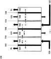
- an electrodialysis cell 100 including a cathode chamber 101 with a cathode (not shown) disposed therein and an anode chamber 102 with an anode (not shown) disposed therein at either end of the cell 100. Disposed between the cathode chamber 101 and anode chamber 102 are chambers 103, 104, 105 and 106.
- cathode chamber 101 and chamber 103 Disposed between: (i) cathode chamber 101 and chamber 103 is cation exchange membrane 107; (ii) chamber 103 and 104 is anion exchange membrane 110; (iii) chamber 104 and 105 is cation exchange membrane 108; (iv) chamber 105 and 106 is anion exchange membrane 111; and (v) chamber 106 and anode chamber 102 is cation exchange membrane 109.
- an electric potential is applied between the cathode in chamber 101 and the anode in chamber 102 to cause electrochemical reactions (7) and (8) to occur and to facilitate migration of ions across the ion exchange membranes.
- Gas for example greenhouse gas is dissolved in an aqueous or non-aqueous solvent (e.g. water-based medium, amine, or other high carbon dioxide solubility solvent) to form solution 120.
- aqueous or non-aqueous solvent e.g. water-based medium, amine, or other high carbon dioxide solubility solvent
- Gas may be dissolved in the solvent externally or in-situ by introducing the gas into the solvent by processes such as bubbling and stream mixing.
- the solubility of the gas in the solvent may be aided by additives such as Ni particles and non-aqueous organic solvents or by application of pressure.
- carbon dioxide dissolves in water to form bicarbonate (HCO 3 - ) and carbonate (CO 3 2- ) ions.
- the bicarbonate and carbonate ions in chamber 103 migrate through anion exchange membrane 110 into chamber 104.
- the cations e.g. protons
- the protons that migrate to the cathode are then reduced in cathodic half-cell reaction (8) leading to the production of hydrogen gas.
- Solution 120 having reduced bicarbonate and carbonate ions exits chamber 103 and is recovered.
- Solution 122 is fed into chamber 105.
- Solution 122 may be any saltwater solution such as brine, seawater or wastewater or any solution being treated to reduce the concentration of ions therein.
- Cations e.g. sodium ions
- anions e.g. chloride ions
- Solution 122 having a reduced ion concentration exits chamber 105 and is recovered.
- Solution 121 is fed into chamber 104 and comprises water or ionic species.
- the solution 121 entering chamber 104 may contain sodium bicarbonate.
- anions e.g. bicarbonate ions
- cations e.g. sodium ions
- Solution 121 with an increased concentration of salt is recovered from chamber 104.
- Solution 123 comprising water or acid is conveyed into chamber 106.
- anions e.g. chloride ions
- chamber 106 anions (e.g. chloride ions) that have migrated into chamber 106 from chamber 105 associate with protons that have migrated into chamber 106 from anode chamber 102 through cation exchange membrane 109.
- These protons are generated by the anodic half-cell reaction (7) of water at the anode in chamber 102.
- the half-cell reaction (7) of water also leads to the production of oxygen at the anode in chamber 102.
- Solution 123 with an increased concentration of acid e.g. hydrochloric acid
- an electrodialysis cell 200 including a cathode (not shown) disposed in chamber 201 and an anode (not shown) disposed in chamber 202 at either end of the cell 200. Disposed between the chambers 201 and 202 are chambers 203, 204, and 205. Disposed between: (i) cathode chamber 201 and chamber 203 is cation exchange membrane 206; (ii) chamber 203 and 204 is cation exchange membrane 207; (iii) chamber 204 and 205 is anion exchange membrane 208; and (iv) chamber 205 and anode chamber 202 is cation exchange membrane 209.
- an electric potential is applied between the cathode in chamber 201 and the anode in chamber 202 to cause electrochemical reactions (7) and (8) to occur and to facilitate migration of ions across the ion exchange membranes.
- Solution 221 is delivered into chamber 204.
- Solution 221 may be any saltwater solution such as brine, seawater or wastewater or any solution being treated to reduce the concentration of ions therein.
- Cations e.g. sodium ions
- anions e.g. chloride ions
- Solution 221 having a reduced ion concentration exits chamber 204 and is recovered.
- Dissolved gas takes the form of related ionic species in solution 220 (see for example reactions (1) to (6)), and solution 220 is delivered into chamber 203.
- the cations (e.g. protons) in chamber 203 migrate through cation exchange membrane 206 and into cathode chamber 201.
- the protons that migrate to the cathode in chamber 201 are then reduced in half-cell reaction (8) leading to the production of hydrogen gas.
- the anions (e.g . bicarbonate ions) in solution 220 remain in chamber 203 and are unable to migrate through either one of cation exchange membrane 206 or 207 which flank chamber 203.
- These anions associate with cations (e.g . sodium ions) that migrate from chamber 204 to chamber 203 through cation exchange membrane 207.
- Solution 220 with an increased concentration of salt (e.g. sodium bicarbonate) is recovered from chamber 203.
- Solution 222 comprising water or acid is delivered into chamber 205.
- anions e.g . chloride ions
- protons that have migrated into chamber 205 from anode chamber 202 through cation exchange membrane 209. These protons are generated by half-cell reaction (7) of water at the anode in chamber 202.
- Solution 222 with an increased concentration of acid e.g. hydrochloric acid is recovered from chamber 205.
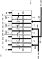
- an electrodialysis cell 300 including a cathode (not shown) disposed in chamber 301 and an anode (not shown) disposed in chamber 302 at either end of the cell 300. Disposed between chambers 301 and 302 are chambers 303 to 310.
- cathode chamber 301 and chamber 303 is cation exchange membrane 311;
- chamber 303 and 304 is anion exchange membrane 312;
- chamber 304 and 305 is cation exchange membrane 313;
- chamber 305 and 306 is anion exchange membrane 314;
- chamber 306 and 307 is cation exchange membrane 315;
- chamber 307 and 308 is anion exchange membrane 316;
- chamber 308 and 309 is cation exchange membrane 317;
- chamber 309 and 310 is anion exchange membrane 318;
- chamber 310 and anode chamber 302 is cation exchange membrane 319.
- an electric potential is applied between the cathode in chamber 301 and the anode in chamber 302 to cause electrochemical reactions (7) and (8) to occur and to facilitate migration of ions across the ion exchange membranes.
- Gas is dissolved into a solvent to form solutions 320 and 324.
- Dissolved gas forms ionic species in solutions 320 and 324.
- ionic species for example, dissolved carbon dioxide in water form bicarbonate (HCO 3 - ) and carbonate (CO 3 2- ) ions.
- Solutions 320 and 324 enter into chambers 303 and 307 respectively.
- the anions (e.g. bicarbonate and carbonate) in chamber 303 migrate through anion exchange membrane 312 into chamber 304.
- the cations (e.g. protons) in chamber 303 migrate through cation exchange membrane 311 and into chamber 301.
- the protons that have migrated to the cathode in chamber 301 are then reduced in half-cell reaction (8) leading to the production of hydrogen gas.
- the anions e.g . bicarbonate and carbonate ions
- the cations e.g. protons
- Solutions 320 and 324 with reduced ionic species exit chambers 303 and 307 respectively, and are recovered.
- Solutions 322 and 326 enter into chambers 305 and 309 respectively.
- Solutions 322 and 326 may be any saltwater solution such as brine, seawater or wastewater, or any solution being treated to reduce the concentration of ions therein.
- Cations (e.g. sodium ions) in chamber 305 migrate through cation exchange membrane 313 into chamber 304.
- Anions (e.g. chloride ions) in chamber 305 migrate through anion exchange membrane 314 into chamber 306.
- cations (e.g. sodium ions) in chamber 309 migrate through cation exchange membrane 317 into chamber 308.
- Anions (e.g. chloride ions) in chamber 309 migrate through the anion exchange membrane 318 into chamber 310.
- Solutions 322 and 326 with a reduced ion concentration exit chambers 305 and 309 respectively, and are recovered.
- Solutions 321 and 325 comprising water or salt are delivered into chambers 304 and 308, respectively.
- the solutions 321 and 325 entering into chambers 304 and 308 respectively may comprise water or sodium bicarbonate.
- anions e.g. bicarbonate ions
- cations e.g. sodium ions
- Solutions 321 and 325 with an increased salt concentration are recovered respectively from chambers 304 and 308.
- Solutions 323 and 327 comprising water or acid are delivered into chambers 306 and 310, respectively.
- Anions e.g. chloride ions
- Anions that have migrated into chamber 306 from chamber 305 associate with protons that have migrated into chamber 306 from chamber 307.
- anions that have migrated into chamber 310 from chamber 309 associate with protons that have migrated into chamber 310 from anode chamber 302.
- These protons are generated by half-cell reaction (7) of water at the anode in chamber 302.
- Solutions 323 and 327 with an increased acid concentration e.g. hydrochloric acid
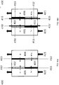
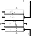
- a dialysis cell 400 comprising chambers 401, 402, 403 and 404. Chambers 402 and 403 are disposed between chambers 401 and 404. An anion exchange membrane 410 is positioned between chamber 401 and chamber 402 and a cation exchange membrane 411 is positioned between chamber 401 and chamber 403. An anion exchange membrane 412 is positioned between chamber 404 and chamber 403 and a cation exchange membrane 413 is positioned between chamber 404 and chamber 402. Conductors 430 and 431 are optionally disposed in chamber 402, and conductors 432 and 433 are optionally disposed in chamber 403 (as depicted in FIG. 4(b) ).
- Solution 420 is delivered into chamber 401.
- Solution 420 may be any saltwater solution such as brine, seawater or wastewater, or any solution being treated to reduce the concentration of ions therein.
- a transport mechanism such as an electric field (as depicted in FIG. 4(b) ) or another transport mechanism such as a concentration gradient (as depicted in FIG. 4(a) )
- cations e.g. sodium ions
- anions e.g. chloride ions
- Solution 420 with a reduced ion concentration exits chamber 401 and is recovered.
- ionic species e.g. bicarbonate ions
- Solution 421 is delivered into chamber 404.
- the cations (e.g. protons) in chamber 404 move through cation exchange membrane 413 and into chamber 402.
- anions e.g. bicarbonate ions
- a concentrated acidic solution e.g. hydrochloric acid solution
- a concentrated salt solution e.g. sodium bicarbonate solution
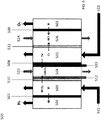
- an electrodialysis cell 500 including a chamber 501 with a cathode (not shown) disposed therein and a chamber 502 with an anode (not shown) disposed therein at either end of the cell 500. Disposed between the cathode chamber 501 and anode chamber 502 are chambers 503, 504, 505 and 506.
- chambers 506 and 502 Disposed between: (i) chamber 501 and chamber 503 is cation exchange membrane 507; (ii) chamber 503 and chamber 504 is anion exchange membrane 510; (iii) chambers 504 and 505 is cation exchange membrane 508; (iv) chambers 505 and 506 is anion exchange membrane 511; and (v) chambers 506 and 502 is cation exchange membrane 509.
- an electric potential is applied between the cathode in chamber 501 and the anode in chamber 502 to cause electrochemical reactions (7) and (8) to occur and to facilitate migration of ions across the ion exchange membranes.
- an electric field may be applied between conductor 512 and conductor 513 that have been optionally disposed within chamber 504.
- Conductors 512, 513 are porous and capable of adsorbing ions due to their pore size.
- Solution 523 is delivered into chamber 505.
- Solution 523 may be any saltwater solution such as brine, seawater or wastewater, or any solution being treated to reduce the concentration of ions therein.
- Cations e.g. sodium ions
- Anions e.g. chloride ions
- anion exchange concentration exits chamber 505 and is recovered.
- ionic species e.g. bicarbonate ions
- Solution 521 is delivered into chamber 503.
- the cations (e.g. protons) in chamber 503 move through cation exchange membrane 507 and into chamber 501.
- the protons that migrate to the cathode in chamber 501 are then reduced in cathodic half-cell reaction (8) leading to the production of hydrogen gas.
- Anions (e.g. bicarbonate ions) in chamber 503 migrate into chamber 504 through anion exchange membrane 510.
- Solution 521 with a reduced concentration of ionic species exits chamber 503 and is recovered.
- Solution 522 comprising water or ionic species is delivered into chamber 504.
- solution 522 may be a solution containing sodium bicarbonate.
- anions e.g. bicarbonate ions
- cations e.g. sodium ions
- Solution 522 with an increased concentration of associated or dissociated ionic species is recovered from chamber 504.
- Solution 524 comprising water or acid is delivered into chamber 506.
- anions e.g. chloride ions
- protons that have migrated into chamber 506 from chamber 505 and through cation exchange membrane 509.
- These protons are generated by the anodic half-cell reaction (7) of water at the anode in chamber 502.
- the half-cell reaction (7) of water also leads to the production of oxygen at the anode in chamber 502.
- Solution 524 with an increased acid concentration e.g. hydrochloric acid
- an electrodialysis cell 600 including a cathode (not shown) disposed in cathode chamber 601 and an anode (not shown) disposed in anode chamber 602 at either end of the cell 600. Disposed between chambers 601 and 602 are chambers 603, 604, and 605.
- cathode chamber 601 and chamber 603 is anion exchange membrane 606;
- chamber 603 and chamber 604 is cation exchange membrane 607;
- chamber 604 and chamber 605 is anion exchange membrane 608; and
- chamber 605 and anode chamber 602 is cation exchange membrane 609.
- an electric potential is applied between the cathode in cathode chamber 601 and the anode in anode chamber 602 to cause the electrochemical reactions (7) and (9) and/or (10a-c) (see below) to occur and to facilitate migration of ions across the ion exchange membranes.
- Solution 623 is delivered into chamber 604.
- Solution 623 may be any saltwater solution such as brine, seawater or wastewater, or any solution being treated to reduce the concentration of ions therein.
- Cations e.g. sodium ions
- Anions e.g. chloride ions
- Solution 623 with a reduced ion concentration exits chamber 604 and is recovered.
- Gas is mixed with oxygen/air to form fluid 621 which is a gas, and fed onto the cathode chamber 601.
- the gas is carbon dioxide gas in fluid 621, and the carbon dioxide may undergo one of the following half-cell reaction at the cathode in chamber 601 depending on different catalysts used in the cell 600 and the operating conditions within the cell ( e.g. temperature, flow rate, humidity, pressure, etc): (9) 1 ⁇ 2O 2(g) + CO 2(g) + 2e - ⁇ CO 3 2- (aq) (FIG. 6(a)) (10a) 1 ⁇ 2O 2(g) + H 2 O (l) + 2e - ⁇ 2OH - (10b) OH + CO 2(g) ⁇ HCO 3 - (FIG.
- the bicarbonate ions, carbonate ions and other ions such as formate ions may be produced electrochemically without the production of hydroxide or chemically by reacting carbon dioxide with hydroxide ions which are generated electrochemically.
- Use of a monovalent anion exchange membrane as anion exchange membrane 606 may selectively allow bicarbonate ions to migrate into chamber 603 whilst carbonate ions may be too large to migrate across the anion exchange membrane 606 into chamber 603.
- Solution 622 comprising water or ionic species is delivered into chamber 603.
- solution 622 may be a solution containing sodium carbonate, sodium bicarbonate or sodium hydroxide.
- anions e.g. carbonate ions, bicarbonate ions or hydroxide ions
- cations e.g. sodium ions
- Solution 622 containing an increased concentration of salt is recovered from chamber 603.
- the recovered solution 622 may also have an increased concentration of a base (e.g. sodium hydroxide).
- Solution 624 comprising water or acid is delivered into chamber 605.
- anions e.g. chloride ions
- protons that have migrated into chamber 605 from anode chamber 602 through cation exchange membrane 609.
- These protons are generated by half-cell reaction (7) of water at the anode in anode chamber 602.
- Solution 624 with an increased acid concentration e.g. hydrochloric acid is recovered from chamber 605.
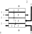
- an electrodialysis cell 700 comprising a cathode in chamber 701 and an anode in chamber 702 at either end of the cell 700. Disposed between the chambers 701 and 702 are chambers 703 and 704. Disposed between: (i) cathode chamber 701 and chamber 703 is cation exchange membrane 710; (ii) chamber 703 and 704 is anion exchange membrane 711; and (iii) chamber 704 and anode chamber 702 is cation exchange membrane 712. In operation, an electric potential is applied between the cathode in chamber 701 and the anode in chamber 702 to cause electrochemical reactions (7) and (9) to occur and to facilitate migration of ions across the ion exchange membranes.
- Solution 721 is delivered into chamber 703.
- Solution 721 may be any saltwater solution such as brine, seawater or wastewater, or any solution being treated to reduce the concentration of ions therein.
- cations e.g. sodium ions
- Anions e.g. chloride ions
- Solution 721 with a reduced ion concentration exits chamber 703 and is recovered.
- Gas is mixed with oxygen/air to form a fluid comprising gas 720, and fed onto the cathode in chamber 701.
- the gas is carbon dioxide gas for example, the carbon dioxide may undergo half-cell reaction (9) at the cathode in chamber 701.
- Carbon dioxide may also be electro-reduced to other charged species such as bicarbonate and formate ions.
- Hydroxide ions (OH - ) may also be produced in the cathode chamber 701 depending on reaction conditions.
- the produced carbonate ions or hydroxide ions associate with the cations (e.g. sodium ions) that have migrated into chamber 701 through cation exchange membrane 710 to form a salt (e.g. sodium carbonate) or a base (e.g. sodium hydroxide).
- Fluid 720 with an increased concentration of salt e.g. sodium carbonate
- the recovered fluid 720 may also have an increased concentration of a base (e.g. sodium hydroxide).
- Solution 722 comprising water or acid is delivered into chamber 704.
- anions e.g. chloride ions
- protons that have migrated into chamber 704 from anode chamber 702 through cation exchange membrane 712.
- solution 722 with an increased concentrated of acid e.g. hydrochloric acid is recovered from chamber 704.
- the electrodialysis and dialysis cells of the described embodiments convert at least a portion of the gas into salt, reduce the ion concentration of the solution being treated and produce an acid solution instead of harmful halogen gas such as chlorine gas.
- the concentrated salt, solution with reduced ion concentration and acid solution may be recovered and used for further application or may be safely disposed.
- FIGS. 1 , 2 , 3 and 5 may be incorporated into a larger system for power generation because of their ability to produce hydrogen gas.
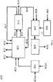
- FIG. 8 there is shown a flow diagram of a gas removal and water treating system 800 not covered by the claims.
- carbon dioxide 801a is dissolved into water 801b to form a CO 2/ H 2 O solution 801.
- the CO 2/ H 2 O solution 801 containing dissolved bicarbonate and carbonate ions is directed into an electrodialysis cell 802 to which power 803 is applied.
- Also entering the electrodialysis cell 802 is a concentrated solution of salt water 804.
- Concentrated salt solution 804 is optionally produced by running salt water 805 (e.g. brine or seawater) through a salt-water treatment process 806 and a salt concentrator step 807. Waste heat 808 is introduced into the salt concentrator to produce concentrated salt solution 804. Excess water recovered during the salt concentrator step 807 is condensed by a condenser 809 to form condensed clean water stream 810.
- salt water 805 e.g. brine or seawater
- Waste heat 808 is introduced into the salt concentrator to produce concentrated salt solution 804.
- Excess water recovered during the salt concentrator step 807 is condensed by a condenser 809 to form condensed clean water stream 810.
- the electrodialysis cell 802 produces a concentrated acidic solution 811, desalinated water stream 812, and concentrated aqueous salt solution 813. Additionally, hydrogen gas 814 and oxygen gas 815 are formed at the cathode and anode respectively of electrodialysis cell 802. Hydrogen gas 814 and oxygen gas 815 are directed towards a power generator 816 for power generation, the products of which are water 817, power 818 and heat 819. Water 817 may be fed back into electrodialysis cell 802, fed into the desalinated water stream 812, fed into the condensed clean water stream 810 or used elsewhere. Heat 819 may be directed towards the salt concentrator step 807 to further accelerate the concentration of salt water. Generated power 818 may be recovered and used for different applications.
- an electrodialysis cell 900 comprising a cathode in chamber 901 and an anode in chamber 902 at either end of the cell 900. Disposed between the chambers 901 and 902 are chambers 903 and 904. Disposed between: (i) cathode chamber 901 and chamber 903 is anion exchange membrane 910; (ii) chamber 903 and 904 is cation exchange membrane 911; and (iii) chamber 904 and anode chamber 902 is anion exchange membrane 912. In operation, an electric potential is applied between the cathode in chamber 901 and the anode in chamber 902 to cause electrochemical reactions (7) and (10) to occur and to facilitate migration of ions across the ion exchange membranes.
- Solution 921 is delivered into chamber 904.
- Solution 921 may be any saltwater solution such as brine, seawater or wastewater, or any solution being treated to reduce the concentration of ions therein.
- cations e.g. sodium ions
- Anions e.g. chloride ions
- Solution 921 with a reduced ion concentration exits chamber 904 and is recovered.
- Gas is mixed with oxygen/air to form fluid 920, and fed onto the cathode in chamber 901.
- the gas is carbon dioxide gas in solution for example
- the carbon dioxide may undergo half-cell reaction (10) at the cathode in chamber 901 to form bicarbonate ions (HCO 3 - ).
- Carbon dioxide may also be electro-reduced to other charged species such as carbonate and formate ions.
- Hydroxide ions (OH - ) may also be produced in the cathode chamber 901 depending on reaction conditions.
- the bicarbonate ions and hydroxide ions migrate across anion exchange membrane 910 into chamber 903 and associate with the cations (e.g. sodium ions) that have migrated into chamber 903 through cation exchange membrane 911 to form a salt (e.g. sodium bicarbonate) and a base (e.g. sodium hydroxide).
- a salt e.g. sodium bicarbonate
- a base e.g. sodium hydroxide
- Solution 922 comprising water or ionic species is delivered into chamber 903.
- solution 922 may be a solution containing sodium bicarbonate or sodium hydroxide.
- anions e.g. bicarbonate ions or hydroxide ions
- cations e.g. sodium ions
- salt e.g. sodium carbonate
- base e.g. sodium hydroxide
- Solution 922 containing an increased concentrated of salt e.g. sodium carbonate
- the recovered solution 922 may also have an increased concentration of a base (e.g. sodium hydroxide).
- additional chambers may be added to the electrodialysis and dialysis cells described herein with reference to Figures 1-7 and 9 .
- two or more dialysis cells may be stacked together in a system for converting gas and treating a solution.
- Each dialysis cell may be an electrodialysis cell, for example the electrodialysis cells shown in Figures 1-3 , 5-7 and 9 , with a cathode and anode included in each cell.
- the stacked system would have a solution (product) feed and a gas feed respectively feeding into the product chamber and the gas chamber of each cell.
- the cathode chamber at an end of one cell may be next to the anode chamber at an end of an adjacent cell in the stacked arrangement.
- the multi-chamber dialysis cell of the disclosed embodiments may be used to carry out a method for reducing ion concentration of a solution and converting gas.
- the dialysis cell has ion exchange barriers separating chambers of the dialysis cell and comprises at least three chambers: (i) a gas chamber; (ii) a product chamber; and (iii) an acid chamber.
- One or more of the chambers may include an electrode.
- the multi-chamber dialysis cell may also include additional chambers such as a salt concentration chamber positioned between the product chamber and the gas chamber.
- a first anion exchange barrier is positioned between the product chamber and the acid chamber and a first cation exchange barrier is positioned between the product chamber and the gas chamber.
- the anion or cation exchange barrier is positioned somewhere between these chambers but not necessarily adjacent or bounding the chambers.
- the method comprises flowing a fluid comprising gas through the gas chamber, and flowing a solution being treated through the product chamber.
- Anions in the solution being treated migrate across the first anion exchange barrier to associate with cations in the acid chamber to form an acid solution in the acid chamber.
- Cations in the solution being treated migrate across the first cation exchange barrier to associate with anions from the fluid comprising gas to form salt.
- the salt may be a carbonate, bicarbonate, formate, sulfate, sulfite, nitrate, nitrite or any other salt depending on the composition of the gas in the fluid.
- the ion concentration of the solution being treated being fed into the product chamber of the dialysis cell may be monitored by an ion concentration sensor or the like positioned in the product chamber or in the manifolding conveying the solution being treated to the product chamber. Conditions within the cell may be controlled such that the ion concentration of the solution exiting the product chamber is within a predetermined range. For example, for the electrodialysis cell of the disclosed embodiments, the electric potential applied between the cathode and the anode may be increased or decreased to respectively increase or decrease desalination of the solution being treated in the cell.
- the salt concentration chamber may include an additional/auxiliary electrode which can be polarized independently from the anode and cathode of the electrodialysis cell.
- the ion concentration of the solution being treated entering the product chamber or the ion concentration of the solution exiting the product chamber may be reduced or increased before or after the solution being treated respectively enters and exits the product chamber by a secondary ion concentration control unit.
- the ion concentration of the solution exiting the product chamber may also be monitored by a ion concentration sensor or the like positioned near or at the outlet of the product chamber or in the manifolding conveying the solution away from the product chamber, to ensure that the solution exiting the product chamber is within the predetermined range. This may be important where there are strict requirements on the ion concentration of solution exiting the product chamber in order for the solution to be recycled, reused or disposed of.
- a controller such as a microprocessor or the like, may receive real time data regarding the concentration of the solution being treated in the product chamber (for example readings from the ion concentration sensors) and may use control algorithms to actuate an automatic response to fluctuations in ion concentration of the solution being treated being fed into the product chamber, for example increasing or decreasing the electric potential applied between the cathode and the anode as discussed above.
- the concentration and/or pH of the acid solution in the acid chamber may be monitored by one or more sensor, such as an ion concentration or pH sensor, positioned in the acid chamber or in the manifolding conveying solution to and away from the acid chamber. Conditions within the cell may be controlled such that the concentration and/or pH of the acid solution in the acid chamber is within a predetermined range. For example, for the electrodialysis cell of the disclosed embodiments, the electric potential applied between the cathode and the anode may be controlled. Other methods for changing the concentration and/or pH of the acid solution in the acid chamber include: changing the flow rate or concentration of solution fed into the salt concentration chamber; changing the number of electrodialysis units used in a system during operation, and/or changing the membrane area used during operation.
- the salt concentration chamber may include an additional/auxiliary electrode which can be polarized independently from the anode and cathode of the electrodialysis cell.
- a controller such as a microprocessor or the like, may receive real time data regarding the concentration and/or pH of the acid solution in the acid chamber and may use control algorithms to actuate an automatic response to fluctuations in concentration and/or pH of the acid solution, for example increasing or decreasing the electric potential applied between the cathode and the anode as discussed above.
- the anode and cathode may contain a catalyst.
- catalysts are known in the art and may be selected for production of different chemical compounds at the anode and/or cathode.
- the catalyst at the cathode may be selected for varying the amounts of bicarbonate (e.g., NaHCO 3 ) or carbonate (e.g., Na 2 CO 3 ) ions being produced in the dialysis cell.
- bicarbonate e.g., NaHCO 3
- carbonate e.g., Na 2 CO 3
- inorganic scaling of ion exchange barriers and/or ion exchange barrier fouling in the dialysis cell may be managed through polarity reversal, periodic flushes or acid washes.
- Another method of in-situ cleaning of the dialysis cell may use porous electrodes (such as mesh electrodes), hereafter referred to as "regenerating electrodes".
- conductors such as the conductors 432 and 433 may be used as regenerating electrodes.
- the regenerating electrodes may be placed on either side of a given ion exchange membrane which may then be polarized as desired.
- the polarizing method may be any galvano or potentiostatic electrochemical method applied by any combination of cycling, pulsed, transient, linear (or otherwise) modes of applying external fields to the regenerating electrodes.
- the applied current or voltage may be DC or AC, or a combination of these (e.g., AC with DC offset).
- This approach may be used for intermittent cleaning or to provide a continuous bias to reduce fouling. It may be useful to apply a voltage across the membrane (or chambers) using these regenerating electrodes for other reasons as well, for example, to reduce voltage requirements at the electrodes and locally increase the voltage gradient across a membrane or chamber that has higher ohmic losses. This may help make the electrode environments less corrosive and increase the lifetime of the cell components and/or the membrane.
- the regenerating electrodes may also act capacitively (i.e. get charged and attract the ions), this may be useful for tuning the ion concentration. Once the electrodes/membrane become fully charged, they can be discharged into a separate tank thus releasing concentrated salt.
- a sequence of automated processes may be possible and the regenerating electrodes may have two-fold functionality: 1) regeneration of the membrane, 2) potential use in ion concentration control.
- Hydrogen sulfide or sour gas is generally an unwanted component of natural gas which is toxic and also causes corrosion. H 2 S combusts with air to form sulfur dioxide (SO 2 ).
- SO 2 sulfur dioxide
- Known processes for removing H 2 S and SO 2 are the Claus process for conversion of H 2 S to sulfur and the Wet Sulfuric Acid (WSA) process which combusts sulfur dioxide (SO 2 ) with oxygen in air eventually forming H 2 SO 4 acid, and heat.
- WSA Wet Sulfuric Acid
- the dialysis cell of the disclosed embodiments may be used to remove H 2 S and/or SO 2 gases flowing through the gas chamber.
- the H 2 S and/or SO 2 may be in the form of gas, humidified gas, or gas dissolved in solution.
- the following reaction may occur: (11) H 2 S + 1.5O 2 ⁇ SO 2 + H 2 O (12) 2O 2 + 2SO 2 + 4e ⁇ 2 SO 4 2-
- the end product may be H 2 SO 4 acid or a salt or a mixture of both.
- the dialysis cell and method of the disclosed embodiments may therefore be useful in the oil and gas sector for removing H 2 S from natural gas.
- one or more ion exchange membranes of the dialysis cell are water permeable and water moves across the water permeable ion exchange membrane into the anode chamber of the dialysis cell from an adjacent chamber and/or water moves across the water permeable ion exchange membrane into the cathode chamber of the dialysis cell from an adjacent chamber. Movement of water into the anode and/or cathode chamber concentrates acid (e.g. HCI) in the acid solution and/or concentrate salt (e.g. Na 2 CO 3 ) in their respective chambers. Movement of water to the anode and/or cathode chambers may be achieved by promoting water flux to these chambers through cell and membrane design.
- acid e.g. HCI
- concentrate salt e.g. Na 2 CO 3
- Movement of the water to the anode and/or cathode chambers and concentration of the acid in the acid solution and/or concentration of the salt occurs in-situ and may therefore be advantageous over external concentrator systems used to remove water to concentrate solutions.
- Operation may be automated by feedback loops using one or more sensors to sense the concentration of the acid solution and/or salt and when an increase/decrease in the concentration is required, the water content of the anode or cathode chamber may be adjusted so that the concentration of the acid solution and/or salt is maintained within a predetermined range.
- the process may be fully automated using a controller.
- the three chamber electrodialysis cell 600 shown in Figure 6(b) was operated with a feed of carbon dioxide and air in fluid 621 in the cathode chamber 601 and an acidic water stream in the anode chamber 602.
- the cathode used a non-selective platinum (Pt) catalyst.
- the feed solution being treated 623 consisted of a 1 M NaCl solution.
- Cell operation started with an initialization of the solutions, by adding 10 mmol HCI to chamber 605 and 10 mmol NaHCO 3 to chamber 603 at the beginning of operation. The cell was operated for a total of eight hours at 3 V. The cell was operated at ambient temperature for the first four hours, then the temperature of the cell was increased to 40°C and the cell was operated at 40°C for the next four hours.
- the cell current density and voltage curves as a function of time are shown in FIG. 10 .
- the cell achieved an average total current of ⁇ 52 mA during ambient operation and ⁇ 84 mA at 40°C which corresponds to current densities of 16 and 26 mA/cm 2 , respectively.
- the pH of the solutions in the salt concentration chamber 603, the product chamber 604 and the acid chamber 605 were monitored periodically throughout the testing period.
- the pH of the solution in the salt concentration chamber 603 and the acid chamber 605 are shown in FIG. 11 .
- FIG. 11 shows production of acid as evidenced by the decrease in pH in the acid chamber 605 (product acid compartment) over time.
- the dotted line shows the expected pH change according to Faraday's law based on the amount of current passed through the electrodialysis cell 600.
- the measured pH change and the calculated Faradaic pH change track closely together and are within the precision of a pH meter.
- Bicarbonate ions are alkaline pH buffers that form a stable pH around pH 8.3.
- the production of bicarbonate and hydroxide ions should increase the alkalinity of the solution in the salt concentration chamber 603. This was clearly observed in FIG. 11 as the pH of the salt in solution (NaHCO 3 ) in the salt concentration chamber 603 (product salt compartment) increased over time indicating the production of bicarbonate and hydroxide ions.
- FIG. 12 shows the change in bicarbonate ion concentration.
- FIG. 12 indicates an increase in production (concentration) of bicarbonate ions ([HCO3 - ]) over time in salt concentration chamber 603.
- the dotted line ([HCO3 - ] Faradaic) shows the expected change in concentration of bicarbonate ions if all current transferred through the electrodialysis cell 600 was converted to bicarbonate ions according to Faraday's law. While the bicarbonate ion concentration in salt concentration chamber 603 increased with time it does not track the expected concentration change as well as the acid concentration as discussed above. This is believed to be due to the use of a non-selective catalyst which also promotes the production of hydroxide and carbonate ions. As the anion exchange membrane 606 positioned between the cathode chamber 601 and the salt concentration chamber 603 was a monovalent anion exchange membrane, carbonate ions should not be have been able to permeate through to the salt concentration chamber 603.
- FIG. 13 shows cell polarization curves (voltage and current density) developed for different concentrations of NaHCO 3 .
- Cell performance improves with increase in concentration as solution resistance within the cell chambers decreases. Similar improvements are expected with increases in the acid concentration. This indicates the cell's ability to handle different concentrations of the feed and products.
- FIG. 14 shows cell polarization curves (voltage and current density) developed for ambient temperature operation as well as operation at 40°C. As shown in FIG. 14 , cell performance improved at 40°C compared to ambient temperature as increasing temperature helps reduce both resistance and kinetic losses. FIG. 11-12 also indicate cell performance improvements over time with an increase in the total product formed for the 8 hour cell operation. This indicates not only the cell's ability for operation at elevated temperatures but also that further increases in temperature may improve cell performance.
Landscapes
- Chemical & Material Sciences (AREA)
- Engineering & Computer Science (AREA)
- Water Supply & Treatment (AREA)
- Chemical Kinetics & Catalysis (AREA)
- Health & Medical Sciences (AREA)
- Urology & Nephrology (AREA)
- Electrochemistry (AREA)
- General Chemical & Material Sciences (AREA)
- Analytical Chemistry (AREA)
- Organic Chemistry (AREA)
- Life Sciences & Earth Sciences (AREA)
- Oil, Petroleum & Natural Gas (AREA)
- Metallurgy (AREA)
- Materials Engineering (AREA)
- Inorganic Chemistry (AREA)
- Molecular Biology (AREA)
- Hydrology & Water Resources (AREA)
- Environmental & Geological Engineering (AREA)
- Separation Using Semi-Permeable Membranes (AREA)
- Water Treatment By Electricity Or Magnetism (AREA)
Description
- The present invention relates to a method for converting gas and treating a solution.
- Greenhouse gas emissions, of which carbon dioxide emissions are a major contributor, are directly linked to climate change. According to the United States Environmental Protection Agency, over 50% of the carbon dioxide emitted in the period between 1990 and 2010 originated from power production and industrial processes. Methods aimed at reducing carbon emissions have included: (i) eliminating carbon consumption at the source by using non-fossil fuel based power sources such as solar, wind, hydroelectric and nuclear; (ii) reducing overall consumption; and (iii) utilizing techniques such as carbon dioxide capture and geological sequestration.
- Several carbon dioxide separation, capturing and conversion processes are known including: (i) combusting fossil fuels with pure oxygen to generate purer carbon dioxide streams; (ii) scrubbing emission sources with solvents such as sodium hydroxide or monoethanolamine to remove carbon dioxide from gaseous streams; (iii) using thermolytic process or membranes to separate the carbon dioxide from other emissions; and (iv) using molecular sieves for the adsorption of carbon dioxide. Geological sequestration of carbon dioxide involves capture and transport of carbon dioxide to suitable sites where it may be stored in deep aquifers, abandoned oil wells, geological formations, soil, or injected into the ocean. However, underground geological mineralization of carbon dioxide is a risky endeavour, and requires at least a detailed knowledge of the characteristics of the storage site, general expenses in pumping the captured greenhouse gas underground, and knowledge of the availability and proximity of underground saline reservoirs to the storage location.
- Water is also a proven medium of greenhouse gas sequestration, as evidenced by the fact that oceans are a major carbon sink in the world. Carbon dioxide undergoes the following reactions in water:
(1) CO2(g) + H2O(l) ⇄ CO2·H2O ⇄ H2CO3(aq)
(2) H2CO3(aq) ⇄HCO3 - (aq) + H+ (aq)
(3) HCO3(aq) + H+ (aq) ⇄CO3 2- (aq) + 2H+ (aq)
Similarly, NOx compounds, such as nitrogen dioxide, undergo the following reactions in water:
(4) 2NO2(g) + H2O(l) → HNO2(aq) + HNO3(aq)
(5) 3HNO2(aq) →HNO3(aq) + 2NO(g) + H2O(l) →H+ (aq) + NO3 - (aq) + 2NO(g) + H2O(l)
Similarly, SOx compounds, such as sulfur dioxide, undergo the following reactions in water:
(6) SO2(g) + H2O(l) →H2SO3(aq) →SO3 2- (aq) + 2H+ (aq)
Such sequestration, however, creates an abundance of ionic species dissolved in water, leaving the water in an ionically contaminated state. - Providing a reliable water source is a rising priority for many jurisdictions as they face population growth. Many industrial processes that consume water produce contaminated water that is unsuitable for reuse. Thus, there is an increasing level of interest in development of technologies that treat waste water. These include desalination by evaporation, reverse osmosis, use of membranes to remove contaminants, and disinfection with ultraviolet and chlorine among others.
- A unit for desalination and greenhouse gas sequestration is disclosed in
WO2012/085552 , which utilizes the principles of the chlor-alkali process. A stream of non-potable water (e.g. seawater) is fed into a separation cell where the stream is electrolyzed using a DC current and ionic species are formed. Cation (e.g. sodium ions) and anion (e.g. chloride ions) species migrate through ion selective membranes in the separation cell. The cations are directed towards a cathodic reaction cell, and the anions are directed towards an anodic reaction cell. Where the anions are chloride ions, for example, chlorine gas is formed at the anode. The ion depleted stream of water is removed from the separation cell for further treatment. Greenhouse gas (e.g. carbon dioxide) is introduced into the cathodic reaction cell where salts such as calcium carbonate and sodium sulfate are formed. Depending on the anions entering the anodic reaction cell, halogen gas such as chlorine gas may be formed in and vented from the anodic reaction cell. This process requires electrochemical reactions, and chlorine gas is produced as a by-product which is potentially dangerous and difficult to handle. In another exemplary system disclosed inUS 7,727,374 , which utilizes the principles of the chlor-alkali process, an apparatus comprising an electrolysis chamber is adapted to produce hydroxide from the electrolysis of water in the presence of a salt. Carbon dioxide is absorbed into this aqueous caustic mixture and reacts with hydroxide to form carbonate and bicarbonate products. Halogen gas such as chlorine gas may also be formed in the process. -
WO 2010/009273 A1 discloses an electrochemical system comprising a cathode compartment partitioned into a first cathode electrolyte compartment and a second cathode electrolyte compartment by a partition, wherein cathode electrolyte in the second cathode electrolyte compartment is in contact with a cathode; and anode electrolyte in an anode compartment is in contact with an anode. -
EP 0 286 143 A1 -
WO 2004/070377 A2 discloses a non-electrolytic apparatus for treating an aqueous sample stream including analyte ions and matrix ions of opposite charge. -
US 2010/0200419 A1 discloses a system comprising an electrochemistry unit comprising a hydrogen-oxidizing anode in communication with a cathode electrolyte, wherein the electrochemistry unit is operably connected to a carbon sequestration system configured to sequester carbon dioxide with the cathode electrolyte. -
WO 2010/087823 A1 discloses an electrochemical system comprising: an anode, a cathode, and a first electrolyte, wherein the system is capable of forming bicarbonate ions in the first electrolyte without forming a gas at the cathode or anode on applying a voltage across the anode and cathode and contacting the first electrolyte with carbon dioxide. - The present disclosure generally relates to systems and methods for converting gas and treating water.
- According to a first aspect of the disclosure, there is provided a method for reducing ion concentration of a solution and converting gas. The method according to the invention is as defined in
claim 1. Other methods are also disclosed according to the first aspect of the disclosure, which are not according to the invention. - According to a second aspect of the disclosure not covered by the claims, there is provided a system for reducing ion concentration of a solution and converting gas comprising: (a) a multi-chamber unitary dialysis cell with ion exchange barriers separating chambers of the dialysis cell, the dialysis cell comprising: (i) a gas chamber; (ii) a product chamber; and (iii) an acid chamber; (b) a manifolding assembly comprising gas chamber manifolding and product chamber manifolding fluidly coupled to the gas chamber and the product chamber respectively; (c) a fluid comprising gas conveyed to and away from the gas chamber by the gas chamber manifolding; and (d) a solution being treated conveyed to and away from the product chamber by the product chamber manifolding. A first anion exchange barrier is positioned between the product chamber and the acid chamber and a first cation exchange barrier is positioned between the product chamber and the gas chamber. Anions in the solution being treated migrate across the first anion exchange barrier to associate with cations in the acid chamber to form an acid solution in the acid chamber, and cations in the solution being treated migrate across the first cation exchange barrier to associate with anions from the fluid comprising gas to form salt, thereby reducing the ion concentration of the solution being treated and converting at least a portion of the gas into salt.
- According to a third aspect of the disclosure not covered by the claims, there is provided a power generation plant comprising the system of the second aspect and a power generator for generating power from hydrogen and oxygen produced by the cathode and anode respectively.
- In the accompanying drawings, which illustrate one or more exemplary embodiments:
-
FIG. 1 is a schematic diagram of a six chamber electrodialysis cell according to an embodiment not covered by the claims. -
FIG. 2 is a schematic diagram of a five chamber electrodialysis cell according to an embodiment not covered by the claims. -
FIG. 3 is a schematic diagram of a ten chamber electrodialysis cell according to an embodiment not covered by the claims. -
FIG. 4(a) is a schematic diagram of a four chamber dialysis cell according to an embodiment not covered by the claims. -
FIG. 4(b) is a schematic diagram of a four chamber dialysis cell according to an embodiment not covered by the claims. -
FIG. 5 is a schematic diagram of a six chamber electrodialysis cell according to an embodiment not covered by the claims. -
FIG. 6(a) andFIG. 6(b) are schematic diagrams of a five chamber electrodialysis cell according to an embodiment useful for understanding the method of the invention. -
FIG. 7 is a schematic diagram of a four chamber electrodialysis cell according to an embodiment not covered by the claims. -
FIG. 8 is a flow diagramof a system incorporating an electrodialysis cell according an embodiment not covered by the claims. -
FIG. 9 is a schematic diagram of a four chamber electrodialysis cell according to an embodiment not covered by the claims. - FIB. 10 is a graph showing operating current and voltage of the electrodialysis cell of
FIG. 6(b) over 8 hours of testing. -
FIG. 11 is a graph showing pH of acid (HCI) in an acid chamber (pH product acid compartment) and pH of salt (NaHCO3) in a salt concentration chamber (pH product salt compartment) of the electrodialysis cell ofFIG. 6(b) over the 8 hours of testing, as well as the expected pH of the acid according to Faraday's law (pH HCI Faradaic). -
FIG. 12 is a graph showing concentration (mmol/l) of bicarbonate ions ([HCO3-]), hydroxide ions ([OH-]) and bicarbonate plus hydroxide ions ([HCO3- ]+[OH-]) in the salt concentration chamber (product salt compartment) of the electrodialysis cell ofFIG. 6(b) over the 8 hours of testing, as well as expected change in concentration of bicarbonate ions according to Faraday's law ([HCO3-] Faradaic). -
FIG. 13 is a graph showing cell polarization curves (current density and voltage) of different concentrations of sodium bicarbonate (NaHCO3). -
FIG. 14 is a graph showing cell polarization curves (current density and voltage) at ambient temperature and 40°C. - Directional terms such as "upper", "lower", "bottom", "top", "right" and "left" are used in the following description for the purpose of providing relative reference only, and are not intended to limit the embodiments of the present disclosure in any way. The plural and singular forms may be used interchangeably without limitation to the embodiments of the present disclosure in any way.
- Embodiments described herein relate to an apparatus (not covered by the claims), system (not covered by the claims) and method for conversion of gas and treating (desalinating) a solution using a multi-chamber unitary dialysis cell comprising a gas chamber, a product chamber, and an acid chamber. One or more walls of each of the gas chamber, product chamber and acid chamber comprise ion exchange barriers which separate the chambers of the dialysis cell. Ionic species (ions) selectively migrate across the ion exchange barriers. According to the method of the invention, the dialysis cell includes a salt concentration chamber positioned between the product chamber and the gas chamber, it is an electrodialysis cell, in which a cathode is disposed in the gas chamber, and a carbon dioxide gas mixed with air/oxygen is flown through the gas chamber. The method of the invention is further defined in
claim 1. Preferred embodiments of the method of the invention are defined in the dependent claims 2-8. The disclosure also describes methods that are not according to the invention. - A solution being treated is fed into the product chamber and cations and anions migrate from the solution in the product chamber to adjacent chambers, thereby reducing the ion concentration of the solution. The solution may be any saltwater solution such as brine, seawater or wastewater, or any solution being treated to reduce the concentration of ions therein, for example industrial waste solutions from oil and gas, mining, forestry, etc. Any type of aqueous or non-aqueous stream consisting of ions or non-ionic species that could be made into ions by the addition of other chemicals or by processing could potentially be utilized.
- In electrodialysis an electric potential gradient may be generated between an anode and cathode. In an aqueous setting, the anode and the cathode generally undergo the following half-cell reactions respectively:
(7) H2O(l) → 2H+ (aq) + ½O2(g) + 2e- (anodic reaction)
(8) 2H+ (aq) + 2e- → H2(g) (cathodic reaction)
The dialysis cell of the disclosed embodiments includes a plurality of chambers, creating a "stack" of chambers, and walls of the chambers comprise ion exchange barriers separating the chambers. Ion exchange barriers (e.g. membranes) in the dialysis cell generally do not require regeneration, thereby reducing the need for chemical inputs over ion exchange processes. Inorganic scaling of ion exchange barriers and ion exchange barrier fouling can be managed through polarity reversal, periodic flushes and/or acid washes. - The ion exchange barriers of the dialysis cell include cation exchange barriers which selectively allow migration of cations, and anion exchange barriers which selectively allow migration of anions. The ion exchange barriers may be water permeable. The ion exchange barriers may be ion exchange membranes and may include, but are not limited to, commercially available bi-polar membranes and membranes with chemical modifications such as: (i) perfluorinated films with fixed pyridine or sulfonic groups; (ii) polyetherketones; (iii) polysulfonones; (iv) polyphenylene oxides; (v) polystyrene; (vi) styrene-divinyl benzene; (vii) polystyrene/acrylic based fabrics with sulfonate and quaternary ammonium cations; (viii) polyfluorinated sulfuric acid polymers; or (ix) resin-polyvinylidenedifluoride fabrics. In alternative embodiments, other ion exchange barriers may be utilized.
- The electrodialysis cells of the described embodiments generally include a cathode and anode, which may be constructed of conductive porous or non-porous substrates, and coated with a catalyst or catalysts. The ion exchange barrier (such as an ion exchange membrane) may alternatively or additionally be coated with a catalyst or catalyst. These catalysts may enhance the rate of reactions in the dialysis cell. Suitable catalysts include, but are not limited to, precious or non-precious transition metals and their compounds (e.g. oxides, nitrides, etc.). The catalysts could be supported onto for example metal, metal oxides, metal nitrides, etc. or unsupported. A mixture of one or more catalysts, option binder and other optional additives (for example hydrophilic and/or hydrophobic additives to control liquid and gas bubble removal), may be applied to the electrode and/or ion exchange barrier by a variety of techniques known in the art, such as spraying, sputtering, screen printing and the like. Fluids can flow in the cell via flow fields (open channels like serpentine, inter-digitated, etc.), porous closed channels, or open pocket. The cell could be operated under pressure or pressure differentials.
- In operation, an electric potential may be applied between the cathode and anode to facilitate the occurrence of electrochemical reactions at the electrodes and migration of ions across the ion exchange membranes. In a dialysis cell, an electric potential may be applied between conductors to create an electric field to enhance migration of ions across the ion exchange membranes and chambers without any electrochemical reactions occurring. However, in methods that are not according to the invention, the application of an electric potential between the conductors is not necessary for operation as ions may diffuse through the ion exchange membranes under the influence of other transport mechanisms such as a concentration gradient.
- In the described embodiments, solutions may be conveyed into and away from chambers of the dialysis cell using a manifolding assembly which may include conduits, optional valves and other equipment known in the art to convey solutions to and away from chambers of a dialysis cell.
- Referring to
FIG. 1 and according to an embodiment not covered by the claims, there is shown anelectrodialysis cell 100 including acathode chamber 101 with a cathode (not shown) disposed therein and ananode chamber 102 with an anode (not shown) disposed therein at either end of thecell 100. Disposed between thecathode chamber 101 andanode chamber 102 arechambers cathode chamber 101 andchamber 103 iscation exchange membrane 107; (ii)chamber anion exchange membrane 110; (iii)chamber cation exchange membrane 108; (iv)chamber anion exchange membrane 111; and (v)chamber 106 andanode chamber 102 iscation exchange membrane 109. In operation, an electric potential is applied between the cathode inchamber 101 and the anode inchamber 102 to cause electrochemical reactions (7) and (8) to occur and to facilitate migration of ions across the ion exchange membranes. - Gas, for example greenhouse gas is dissolved in an aqueous or non-aqueous solvent (e.g. water-based medium, amine, or other high carbon dioxide solubility solvent) to form
solution 120. Gas may be dissolved in the solvent externally or in-situ by introducing the gas into the solvent by processes such as bubbling and stream mixing. The solubility of the gas in the solvent may be aided by additives such as Ni particles and non-aqueous organic solvents or by application of pressure. Using carbon dioxide as the gas and water as the solvent as an example, carbon dioxide dissolves in water to form bicarbonate (HCO3 -) and carbonate (CO3 2-) ions. The bicarbonate and carbonate ions inchamber 103 migrate throughanion exchange membrane 110 intochamber 104. Similarly, the cations (e.g. protons) migrate throughcation exchange membrane 107 towards the cathode inchamber 101. The protons that migrate to the cathode are then reduced in cathodic half-cell reaction (8) leading to the production of hydrogen gas.Solution 120 having reduced bicarbonate and carbonate ions exitschamber 103 and is recovered. -
Solution 122 is fed intochamber 105.Solution 122 may be any saltwater solution such as brine, seawater or wastewater or any solution being treated to reduce the concentration of ions therein. Cations (e.g. sodium ions) inchamber 105 migrate throughcation exchange membrane 108 intochamber 104. Similarly, anions (e.g. chloride ions) inchamber 105 migrate throughanion exchange membrane 111 intochamber 106.Solution 122 having a reduced ion concentration exitschamber 105 and is recovered. -
Solution 121 is fed intochamber 104 and comprises water or ionic species. For example, wheresolution 120 is carbon dioxide dissolved in water andsolution 122 is brine, thesolution 121 enteringchamber 104 may contain sodium bicarbonate. Inchamber 104, anions (e.g. bicarbonate ions) that have migrated intochamber 104 fromchamber 103 associate with cations (e.g. sodium ions) that have migrated intochamber 104 fromchamber 105.Solution 121 with an increased concentration of salt (e.g. sodium bicarbonate) is recovered fromchamber 104. -
Solution 123 comprising water or acid is conveyed intochamber 106. Inchamber 106, anions (e.g. chloride ions) that have migrated intochamber 106 fromchamber 105 associate with protons that have migrated intochamber 106 fromanode chamber 102 throughcation exchange membrane 109. These protons are generated by the anodic half-cell reaction (7) of water at the anode inchamber 102. The half-cell reaction (7) of water also leads to the production of oxygen at the anode inchamber 102.Solution 123 with an increased concentration of acid (e.g. hydrochloric acid) is recovered fromchamber 106. - Referring to
FIG. 2 and according to an alternative embodiment not covered by the claims, there is shown anelectrodialysis cell 200 including a cathode (not shown) disposed inchamber 201 and an anode (not shown) disposed inchamber 202 at either end of thecell 200. Disposed between thechambers chambers cathode chamber 201 andchamber 203 iscation exchange membrane 206; (ii)chamber cation exchange membrane 207; (iii)chamber anion exchange membrane 208; and (iv)chamber 205 andanode chamber 202 iscation exchange membrane 209. In operation, an electric potential is applied between the cathode inchamber 201 and the anode inchamber 202 to cause electrochemical reactions (7) and (8) to occur and to facilitate migration of ions across the ion exchange membranes. - Solution 221 is delivered into
chamber 204. Solution 221 may be any saltwater solution such as brine, seawater or wastewater or any solution being treated to reduce the concentration of ions therein. Cations (e.g. sodium ions) inchamber 204 migrate throughcation exchange membrane 207 and intochamber 203. Similarly, anions (e.g. chloride ions) inchamber 204 migrate throughanion exchange membrane 208 and intochamber 205. Solution 221 having a reduced ion concentration exitschamber 204 and is recovered. - Gas is dissolved into a solvent to form
solution 220. Dissolved gas takes the form of related ionic species in solution 220 (see for example reactions (1) to (6)), andsolution 220 is delivered intochamber 203. The cations (e.g. protons) inchamber 203 migrate throughcation exchange membrane 206 and intocathode chamber 201. The protons that migrate to the cathode inchamber 201 are then reduced in half-cell reaction (8) leading to the production of hydrogen gas. The anions (e.g. bicarbonate ions) insolution 220 remain inchamber 203 and are unable to migrate through either one ofcation exchange membrane chamber 203. These anions associate with cations (e.g. sodium ions) that migrate fromchamber 204 tochamber 203 throughcation exchange membrane 207.Solution 220 with an increased concentration of salt (e.g. sodium bicarbonate) is recovered fromchamber 203. -
Solution 222 comprising water or acid is delivered intochamber 205. Inchamber 205, anions (e.g. chloride ions) that have migrated intochamber 205 fromchamber 204 associate with protons that have migrated intochamber 205 fromanode chamber 202 throughcation exchange membrane 209. These protons are generated by half-cell reaction (7) of water at the anode inchamber 202.Solution 222 with an increased concentration of acid (e.g. hydrochloric acid) is recovered fromchamber 205. - Referring to
FIG. 3 and according to an alternative embodiment not covered by the claims, there is shown anelectrodialysis cell 300 including a cathode (not shown) disposed inchamber 301 and an anode (not shown) disposed inchamber 302 at either end of thecell 300. Disposed betweenchambers chambers 303 to 310. Disposed between: (i)cathode chamber 301 andchamber 303 iscation exchange membrane 311; (ii)chamber anion exchange membrane 312; (iii)chamber cation exchange membrane 313; (iv)chamber anion exchange membrane 314; (v)chamber cation exchange membrane 315; (vi)chamber anion exchange membrane 316; (vii)chamber cation exchange membrane 317; (viii)chamber anion exchange membrane 318; and (ix)chamber 310 andanode chamber 302 iscation exchange membrane 319. In operation, an electric potential is applied between the cathode inchamber 301 and the anode inchamber 302 to cause electrochemical reactions (7) and (8) to occur and to facilitate migration of ions across the ion exchange membranes. - Gas is dissolved into a solvent to form
solutions solutions Solutions chambers chamber 303 migrate throughanion exchange membrane 312 intochamber 304. The cations (e.g. protons) inchamber 303 migrate throughcation exchange membrane 311 and intochamber 301. The protons that have migrated to the cathode inchamber 301 are then reduced in half-cell reaction (8) leading to the production of hydrogen gas. Similarly, the anions (e.g. bicarbonate and carbonate ions) inchamber 307 migrate throughanion exchange membrane 316 intochamber 308. The cations (e.g. protons) inchamber 307 migrate throughcation exchange membrane 315 intochamber 306.Solutions species exit chambers -
Solutions chambers Solutions chamber 305 migrate throughcation exchange membrane 313 intochamber 304. Anions (e.g. chloride ions) inchamber 305 migrate throughanion exchange membrane 314 intochamber 306. Similarly, cations (e.g. sodium ions) inchamber 309 migrate throughcation exchange membrane 317 intochamber 308. Anions (e.g. chloride ions) inchamber 309 migrate through theanion exchange membrane 318 intochamber 310.Solutions concentration exit chambers -
Solutions chambers solutions solutions solutions chambers chambers Solutions chambers -
Solutions chambers chamber 306 fromchamber 305 associate with protons that have migrated intochamber 306 fromchamber 307. Similarly, anions that have migrated intochamber 310 fromchamber 309 associate with protons that have migrated intochamber 310 fromanode chamber 302. These protons are generated by half-cell reaction (7) of water at the anode inchamber 302.Solutions chambers - Referring to
FIGS. 4(a) and 4(b) , and according to an alternative embodiment not covered by the claims, there is shown adialysis cell 400 comprisingchambers Chambers chambers anion exchange membrane 410 is positioned betweenchamber 401 andchamber 402 and acation exchange membrane 411 is positioned betweenchamber 401 andchamber 403. Ananion exchange membrane 412 is positioned betweenchamber 404 andchamber 403 and acation exchange membrane 413 is positioned betweenchamber 404 andchamber 402.Conductors chamber 402, andconductors FIG. 4(b) ). -
Solution 420 is delivered intochamber 401.Solution 420 may be any saltwater solution such as brine, seawater or wastewater, or any solution being treated to reduce the concentration of ions therein. Under the influence of a transport mechanism such as an electric field (as depicted inFIG. 4(b) ) or another transport mechanism such as a concentration gradient (as depicted inFIG. 4(a) ), cations (e.g. sodium ions) inchamber 401 migrate intochamber 403 throughcation exchange membrane 411. Similarly, anions (e.g. chloride ions) inchamber 401 migrate intochamber 402 throughanion exchange membrane 410.Solution 420 with a reduced ion concentration exitschamber 401 and is recovered. - Gas is dissolved into a solvent to form
solution 421. Dissolved gas forms ionic species (e.g. bicarbonate ions) insolution 421.Solution 421 is delivered intochamber 404. The cations (e.g. protons) inchamber 404 move throughcation exchange membrane 413 and intochamber 402. Similarly, anions (e.g. bicarbonate ions) inchamber 404 migrate intochamber 403 throughanion exchange membrane 412.Solution 421 with a reduced concentration of ionic species exitschamber 404 and is recovered. - As a result of the migration of ionic species into
chambers chambers - Referring to
FIG. 5 and according to an alternative embodiment not covered by the claims, there is shown anelectrodialysis cell 500 including achamber 501 with a cathode (not shown) disposed therein and achamber 502 with an anode (not shown) disposed therein at either end of thecell 500. Disposed between thecathode chamber 501 andanode chamber 502 arechambers chamber 501 andchamber 503 iscation exchange membrane 507; (ii)chamber 503 andchamber 504 isanion exchange membrane 510; (iii)chambers cation exchange membrane 508; (iv)chambers anion exchange membrane 511; and (v)chambers cation exchange membrane 509. In operation, an electric potential is applied between the cathode inchamber 501 and the anode inchamber 502 to cause electrochemical reactions (7) and (8) to occur and to facilitate migration of ions across the ion exchange membranes. - To facilitate ionic transport into
chamber 504, an electric field may be applied betweenconductor 512 andconductor 513 that have been optionally disposed withinchamber 504.Conductors -
Solution 523 is delivered intochamber 505.Solution 523 may be any saltwater solution such as brine, seawater or wastewater, or any solution being treated to reduce the concentration of ions therein. Cations (e.g. sodium ions) inchamber 505 migrate intochamber 504 throughcation exchange membrane 508. Anions (e.g. chloride ions) inchamber 505 migrate through the anion exchange concentration exitschamber 505 and is recovered. - Gas is dissolved into a solvent to form
solution 521. Dissolved gas forms ionic species (e.g. bicarbonate ions) insolution 521.Solution 521 is delivered intochamber 503. The cations (e.g. protons) inchamber 503 move throughcation exchange membrane 507 and intochamber 501. The protons that migrate to the cathode inchamber 501 are then reduced in cathodic half-cell reaction (8) leading to the production of hydrogen gas. Anions (e.g. bicarbonate ions) inchamber 503 migrate intochamber 504 throughanion exchange membrane 510.Solution 521 with a reduced concentration of ionic species exitschamber 503 and is recovered. -
Solution 522 comprising water or ionic species is delivered intochamber 504. For example,solution 522 may be a solution containing sodium bicarbonate. Inchamber 504, anions (e.g. bicarbonate ions) associate with cations (e.g. sodium ions).Solution 522 with an increased concentration of associated or dissociated ionic species (e.g. sodium bicarbonate) is recovered fromchamber 504. -
Solution 524 comprising water or acid is delivered intochamber 506. Inchamber 506, anions (e.g. chloride ions) that have migrated intochamber 506 fromchamber 505 associate with protons that have migrated intochamber 506 fromchamber 502 and throughcation exchange membrane 509. These protons are generated by the anodic half-cell reaction (7) of water at the anode inchamber 502. The half-cell reaction (7) of water also leads to the production of oxygen at the anode inchamber 502.Solution 524 with an increased acid concentration (e.g. hydrochloric acid) is recovered fromchamber 506. - Referring to
FIG. 6(a) and FIB. 6(b) and according to another embodiment useful for understanding the method of the invention, there is shown anelectrodialysis cell 600 including a cathode (not shown) disposed incathode chamber 601 and an anode (not shown) disposed inanode chamber 602 at either end of thecell 600. Disposed betweenchambers chambers cathode chamber 601 andchamber 603 isanion exchange membrane 606; (ii)chamber 603 andchamber 604 iscation exchange membrane 607; (iii)chamber 604 andchamber 605 isanion exchange membrane 608; and (iv)chamber 605 andanode chamber 602 iscation exchange membrane 609. In operation, an electric potential is applied between the cathode incathode chamber 601 and the anode inanode chamber 602 to cause the electrochemical reactions (7) and (9) and/or (10a-c) (see below) to occur and to facilitate migration of ions across the ion exchange membranes. -
Solution 623 is delivered intochamber 604.Solution 623 may be any saltwater solution such as brine, seawater or wastewater, or any solution being treated to reduce the concentration of ions therein. Cations (e.g. sodium ions) inchamber 604 migrate intochamber 603 throughcation exchange membrane 607. Anions (e.g. chloride ions) inchamber 604 migrate through theanion exchange membrane 608 and intochamber 605.Solution 623 with a reduced ion concentration exitschamber 604 and is recovered. - Gas is mixed with oxygen/air to form fluid 621 which is a gas, and fed onto the
cathode chamber 601. The gas is carbon dioxide gas influid 621, and the carbon dioxide may undergo one of the following half-cell reaction at the cathode inchamber 601 depending on different catalysts used in thecell 600 and the operating conditions within the cell (e.g. temperature, flow rate, humidity, pressure, etc):
(9) ½O2(g) + CO2(g) + 2e- · CO3 2- (aq) (FIG. 6(a))
(10a) ½O2(g) + H2O(l) + 2e- → 2OH-
(10b) OH + CO2(g) →HCO3- (FIG. 6(b))
(10c) HCO3 - + OH- → CO3 2- + H2O(l)
Carbon dioxide gas is also electro-reduced to other charged species such as formate ions. The type of half-cell reaction at the cathode may depend on reaction conditions and reactor operating conditions. Gas that does not participate in half-cell reactions, such as nitrogen gas in air, are vented. The produced carbonate ions (CO3 2-), bicarbonate ions (HCO3 -), hydroxide ions (OH-) (or other charged species such as formate ions) migrate throughanion exchange membrane 606 intochamber 603. The bicarbonate ions, carbonate ions and other ions such as formate ions, may be produced electrochemically without the production of hydroxide or chemically by reacting carbon dioxide with hydroxide ions which are generated electrochemically. Use of a monovalent anion exchange membrane asanion exchange membrane 606 may selectively allow bicarbonate ions to migrate intochamber 603 whilst carbonate ions may be too large to migrate across theanion exchange membrane 606 intochamber 603. -
Solution 622 comprising water or ionic species is delivered intochamber 603. For example,solution 622 may be a solution containing sodium carbonate, sodium bicarbonate or sodium hydroxide. Inchamber 603, anions (e.g. carbonate ions, bicarbonate ions or hydroxide ions) associate with cations (e.g. sodium ions) to form a salt or a base (e.g. sodium carbonate, sodium bicarbonate or sodium hydroxide).Solution 622 containing an increased concentration of salt (e.g. sodium carbonate or sodium bicarbonate) is recovered fromchamber 603. The recoveredsolution 622 may also have an increased concentration of a base (e.g. sodium hydroxide). -
Solution 624 comprising water or acid is delivered intochamber 605. Inchamber 605, anions (e.g. chloride ions) that have migrated intochamber 605 fromchamber 604 associate with protons that have migrated intochamber 605 fromanode chamber 602 throughcation exchange membrane 609. These protons are generated by half-cell reaction (7) of water at the anode inanode chamber 602.Solution 624 with an increased acid concentration (e.g. hydrochloric acid) is recovered fromchamber 605. - Referring to
FIG. 7 and according to another embodiment not covered by the claims, there is shown anelectrodialysis cell 700 comprising a cathode inchamber 701 and an anode inchamber 702 at either end of thecell 700. Disposed between thechambers chambers cathode chamber 701 andchamber 703 iscation exchange membrane 710; (ii)chamber anion exchange membrane 711; and (iii)chamber 704 andanode chamber 702 iscation exchange membrane 712. In operation, an electric potential is applied between the cathode inchamber 701 and the anode inchamber 702 to cause electrochemical reactions (7) and (9) to occur and to facilitate migration of ions across the ion exchange membranes. -
Solution 721 is delivered intochamber 703.Solution 721 may be any saltwater solution such as brine, seawater or wastewater, or any solution being treated to reduce the concentration of ions therein. Under the influence of a transport mechanism, cations (e.g. sodium ions) inchamber 703 migrate intocathode 701 throughcation exchange membrane 710. Anions (e.g. chloride ions) inchamber 703 migrate through theanion exchange membrane 711 intochamber 704.Solution 721 with a reduced ion concentration exitschamber 703 and is recovered. - Gas is mixed with oxygen/air to form a
fluid comprising gas 720, and fed onto the cathode inchamber 701. When the gas is carbon dioxide gas for example, the carbon dioxide may undergo half-cell reaction (9) at the cathode inchamber 701. Carbon dioxide may also be electro-reduced to other charged species such as bicarbonate and formate ions. Hydroxide ions (OH-) may also be produced in thecathode chamber 701 depending on reaction conditions. The produced carbonate ions or hydroxide ions associate with the cations (e.g. sodium ions) that have migrated intochamber 701 throughcation exchange membrane 710 to form a salt (e.g. sodium carbonate) or a base (e.g. sodium hydroxide).Fluid 720 with an increased concentration of salt (e.g. sodium carbonate) is recovered fromchamber 701. The recoveredfluid 720 may also have an increased concentration of a base (e.g. sodium hydroxide). -
Solution 722 comprising water or acid is delivered intochamber 704. Inchamber 704, anions (e.g. chloride ions) that have migrated intochamber 704 fromchamber 703 associate with protons that have migrated intochamber 704 fromanode chamber 702 throughcation exchange membrane 712. These protons are generated by half-cell reaction (7) of water at the anode inchamber 702.Solution 722 with an increased concentrated of acid (e.g. hydrochloric acid) is recovered fromchamber 704. - The electrodialysis and dialysis cells of the described embodiments convert at least a portion of the gas into salt, reduce the ion concentration of the solution being treated and produce an acid solution instead of harmful halogen gas such as chlorine gas. The concentrated salt, solution with reduced ion concentration and acid solution may be recovered and used for further application or may be safely disposed.
-
Cells FIGS. 1 ,2 ,3 and5 respectively may be incorporated into a larger system for power generation because of their ability to produce hydrogen gas. Referring toFIG. 8 , there is shown a flow diagram of a gas removal andwater treating system 800 not covered by the claims. In an exemplary embodiment using carbon dioxide as the gas and water as the solvent,carbon dioxide 801a is dissolved intowater 801b to form a CO2/H2O solution 801. The CO2/H2O solution 801 containing dissolved bicarbonate and carbonate ions is directed into anelectrodialysis cell 802 to whichpower 803 is applied. Also entering theelectrodialysis cell 802 is a concentrated solution ofsalt water 804.Concentrated salt solution 804 is optionally produced by running salt water 805 (e.g. brine or seawater) through a salt-water treatment process 806 and asalt concentrator step 807.Waste heat 808 is introduced into the salt concentrator to produceconcentrated salt solution 804. Excess water recovered during thesalt concentrator step 807 is condensed by acondenser 809 to form condensedclean water stream 810. - As exemplified by
cells FIGS. 1 ,2 ,3 and5 , theelectrodialysis cell 802 produces a concentratedacidic solution 811,desalinated water stream 812, and concentratedaqueous salt solution 813. Additionally,hydrogen gas 814 andoxygen gas 815 are formed at the cathode and anode respectively ofelectrodialysis cell 802.Hydrogen gas 814 andoxygen gas 815 are directed towards apower generator 816 for power generation, the products of which arewater 817,power 818 andheat 819.Water 817 may be fed back intoelectrodialysis cell 802, fed into thedesalinated water stream 812, fed into the condensedclean water stream 810 or used elsewhere.Heat 819 may be directed towards thesalt concentrator step 807 to further accelerate the concentration of salt water. Generatedpower 818 may be recovered and used for different applications. - Referring to
FIG. 9 and according to another embodiment not covered by the claims, there is shown an electrodialysis cell 900 comprising a cathode inchamber 901 and an anode inchamber 902 at either end of the cell 900. Disposed between thechambers chambers cathode chamber 901 andchamber 903 isanion exchange membrane 910; (ii)chamber cation exchange membrane 911; and (iii)chamber 904 andanode chamber 902 isanion exchange membrane 912. In operation, an electric potential is applied between the cathode inchamber 901 and the anode inchamber 902 to cause electrochemical reactions (7) and (10) to occur and to facilitate migration of ions across the ion exchange membranes. -
Solution 921 is delivered intochamber 904.Solution 921 may be any saltwater solution such as brine, seawater or wastewater, or any solution being treated to reduce the concentration of ions therein. Under the influence of a transport mechanism, cations (e.g. sodium ions) inchamber 904 migrate intochamber 903 throughcation exchange membrane 911. Anions (e.g. chloride ions) inchamber 904 migrate through theanion exchange membrane 912 intoanode chamber 902 and associate with protons (H+) in theanode chamber 902 to form acid (e.g. HCI) .Solution 921 with a reduced ion concentration exitschamber 904 and is recovered. - Gas is mixed with oxygen/air to form fluid 920, and fed onto the cathode in
chamber 901. When the gas is carbon dioxide gas in solution for example, the carbon dioxide may undergo half-cell reaction (10) at the cathode inchamber 901 to form bicarbonate ions (HCO3 -). Carbon dioxide may also be electro-reduced to other charged species such as carbonate and formate ions. Hydroxide ions (OH-) may also be produced in thecathode chamber 901 depending on reaction conditions. The bicarbonate ions and hydroxide ions migrate acrossanion exchange membrane 910 intochamber 903 and associate with the cations (e.g. sodium ions) that have migrated intochamber 903 throughcation exchange membrane 911 to form a salt (e.g. sodium bicarbonate) and a base (e.g. sodium hydroxide). -
Solution 922 comprising water or ionic species is delivered intochamber 903. For example,solution 922 may be a solution containing sodium bicarbonate or sodium hydroxide. Inchamber 903, anions (e.g. bicarbonate ions or hydroxide ions) associate with cations (e.g. sodium ions) to form salt (e.g. sodium carbonate) or a base (e.g. sodium hydroxide).Solution 922 containing an increased concentrated of salt (e.g. sodium carbonate) is recovered fromchamber 903. The recoveredsolution 922 may also have an increased concentration of a base (e.g. sodium hydroxide). - In alternative embodiments (not shown), additional chambers may be added to the electrodialysis and dialysis cells described herein with reference to
Figures 1-7 and9 . In alternative embodiments two or more dialysis cells may be stacked together in a system for converting gas and treating a solution. Each dialysis cell may be an electrodialysis cell, for example the electrodialysis cells shown inFigures 1-3 ,5-7 and9 , with a cathode and anode included in each cell. The stacked system would have a solution (product) feed and a gas feed respectively feeding into the product chamber and the gas chamber of each cell. The cathode chamber at an end of one cell may be next to the anode chamber at an end of an adjacent cell in the stacked arrangement. - The multi-chamber dialysis cell of the disclosed embodiments may be used to carry out a method for reducing ion concentration of a solution and converting gas. The dialysis cell has ion exchange barriers separating chambers of the dialysis cell and comprises at least three chambers: (i) a gas chamber; (ii) a product chamber; and (iii) an acid chamber. One or more of the chambers may include an electrode. The multi-chamber dialysis cell may also include additional chambers such as a salt concentration chamber positioned between the product chamber and the gas chamber. A first anion exchange barrier is positioned between the product chamber and the acid chamber and a first cation exchange barrier is positioned between the product chamber and the gas chamber. The anion or cation exchange barrier is positioned somewhere between these chambers but not necessarily adjacent or bounding the chambers. The method comprises flowing a fluid comprising gas through the gas chamber, and flowing a solution being treated through the product chamber. Anions in the solution being treated migrate across the first anion exchange barrier to associate with cations in the acid chamber to form an acid solution in the acid chamber. Cations in the solution being treated migrate across the first cation exchange barrier to associate with anions from the fluid comprising gas to form salt. As a result the ion concentration of the solution being treated is reduced and at least a portion of the gas is converted into salt. The salt may be a carbonate, bicarbonate, formate, sulfate, sulfite, nitrate, nitrite or any other salt depending on the composition of the gas in the fluid.
- The ion concentration of the solution being treated being fed into the product chamber of the dialysis cell may be monitored by an ion concentration sensor or the like positioned in the product chamber or in the manifolding conveying the solution being treated to the product chamber. Conditions within the cell may be controlled such that the ion concentration of the solution exiting the product chamber is within a predetermined range. For example, for the electrodialysis cell of the disclosed embodiments, the electric potential applied between the cathode and the anode may be increased or decreased to respectively increase or decrease desalination of the solution being treated in the cell. Other methods for changing the concentration of the solution exiting the product chamber include: changing the flow rate or concentration of solution fed into the salt concentration chamber; changing the number of electrodialysis units used in a system during operation, and/or changing the membrane area used during operation. In one embodiment, the salt concentration chamber may include an additional/auxiliary electrode which can be polarized independently from the anode and cathode of the electrodialysis cell. In additional embodiments the ion concentration of the solution being treated entering the product chamber or the ion concentration of the solution exiting the product chamber may be reduced or increased before or after the solution being treated respectively enters and exits the product chamber by a secondary ion concentration control unit. The ion concentration of the solution exiting the product chamber may also be monitored by a ion concentration sensor or the like positioned near or at the outlet of the product chamber or in the manifolding conveying the solution away from the product chamber, to ensure that the solution exiting the product chamber is within the predetermined range. This may be important where there are strict requirements on the ion concentration of solution exiting the product chamber in order for the solution to be recycled, reused or disposed of. A controller, such as a microprocessor or the like, may receive real time data regarding the concentration of the solution being treated in the product chamber (for example readings from the ion concentration sensors) and may use control algorithms to actuate an automatic response to fluctuations in ion concentration of the solution being treated being fed into the product chamber, for example increasing or decreasing the electric potential applied between the cathode and the anode as discussed above.
- The concentration and/or pH of the acid solution in the acid chamber may be monitored by one or more sensor, such as an ion concentration or pH sensor, positioned in the acid chamber or in the manifolding conveying solution to and away from the acid chamber. Conditions within the cell may be controlled such that the concentration and/or pH of the acid solution in the acid chamber is within a predetermined range. For example, for the electrodialysis cell of the disclosed embodiments, the electric potential applied between the cathode and the anode may be controlled. Other methods for changing the concentration and/or pH of the acid solution in the acid chamber include: changing the flow rate or concentration of solution fed into the salt concentration chamber; changing the number of electrodialysis units used in a system during operation, and/or changing the membrane area used during operation. In one embodiment, the salt concentration chamber may include an additional/auxiliary electrode which can be polarized independently from the anode and cathode of the electrodialysis cell. A controller, such as a microprocessor or the like, may receive real time data regarding the concentration and/or pH of the acid solution in the acid chamber and may use control algorithms to actuate an automatic response to fluctuations in concentration and/or pH of the acid solution, for example increasing or decreasing the electric potential applied between the cathode and the anode as discussed above.
- As discussed above the anode and cathode may contain a catalyst. Such catalysts are known in the art and may be selected for production of different chemical compounds at the anode and/or cathode. For example, the catalyst at the cathode may be selected for varying the amounts of bicarbonate (e.g., NaHCO3) or carbonate (e.g., Na2CO3) ions being produced in the dialysis cell.
- As discussed above, inorganic scaling of ion exchange barriers and/or ion exchange barrier fouling in the dialysis cell may be managed through polarity reversal, periodic flushes or acid washes. Another method of in-situ cleaning of the dialysis cell may use porous electrodes (such as mesh electrodes), hereafter referred to as "regenerating electrodes". In one embodiment, conductors, such as the
conductors - Hydrogen sulfide or sour gas (H2S) is generally an unwanted component of natural gas which is toxic and also causes corrosion. H2S combusts with air to form sulfur dioxide (SO2). Known processes for removing H2S and SO2 are the Claus process for conversion of H2S to sulfur and the Wet Sulfuric Acid (WSA) process which combusts sulfur dioxide (SO2) with oxygen in air eventually forming H2SO4 acid, and heat. The dialysis cell of the disclosed embodiments may be used to remove H2S and/or SO2 gases flowing through the gas chamber. The H2S and/or SO2 may be in the form of gas, humidified gas, or gas dissolved in solution. At the cathode, the following reaction may occur:
(11) H2S + 1.5O2 →SO2 + H2O
(12) 2O2 + 2SO2 + 4e → 2 SO4 2-
- The end product may be H2SO4 acid or a salt or a mixture of both. The dialysis cell and method of the disclosed embodiments may therefore be useful in the oil and gas sector for removing H2S from natural gas.
- In a further embodiment one or more ion exchange membranes of the dialysis cell are water permeable and water moves across the water permeable ion exchange membrane into the anode chamber of the dialysis cell from an adjacent chamber and/or water moves across the water permeable ion exchange membrane into the cathode chamber of the dialysis cell from an adjacent chamber. Movement of water into the anode and/or cathode chamber concentrates acid (e.g. HCI) in the acid solution and/or concentrate salt (e.g. Na2CO3) in their respective chambers. Movement of water to the anode and/or cathode chambers may be achieved by promoting water flux to these chambers through cell and membrane design. Movement of the water to the anode and/or cathode chambers and concentration of the acid in the acid solution and/or concentration of the salt occurs in-situ and may therefore be advantageous over external concentrator systems used to remove water to concentrate solutions. Operation may be automated by feedback loops using one or more sensors to sense the concentration of the acid solution and/or salt and when an increase/decrease in the concentration is required, the water content of the anode or cathode chamber may be adjusted so that the concentration of the acid solution and/or salt is maintained within a predetermined range. The process may be fully automated using a controller.
- The three
chamber electrodialysis cell 600 shown inFigure 6(b) was operated with a feed of carbon dioxide and air influid 621 in thecathode chamber 601 and an acidic water stream in theanode chamber 602. The cathode used a non-selective platinum (Pt) catalyst. The feed solution being treated 623 consisted of a 1 M NaCl solution. Cell operation started with an initialization of the solutions, by adding 10 mmol HCI tochamber chamber 603 at the beginning of operation. The cell was operated for a total of eight hours at 3 V. The cell was operated at ambient temperature for the first four hours, then the temperature of the cell was increased to 40°C and the cell was operated at 40°C for the next four hours. The cell current density and voltage curves as a function of time are shown inFIG. 10 . Overall, the cell achieved an average total current of ~52 mA during ambient operation and ~84 mA at 40°C which corresponds to current densities of 16 and 26 mA/cm2, respectively. - The pH of the solutions in the
salt concentration chamber 603, theproduct chamber 604 and theacid chamber 605 were monitored periodically throughout the testing period. The pH of the solution in thesalt concentration chamber 603 and theacid chamber 605 are shown inFIG. 11 . -
FIG. 11 shows production of acid as evidenced by the decrease in pH in the acid chamber 605 (product acid compartment) over time. The dotted line (pH HCI Faradaic) shows the expected pH change according to Faraday's law based on the amount of current passed through theelectrodialysis cell 600. The measured pH change and the calculated Faradaic pH change track closely together and are within the precision of a pH meter. - Bicarbonate ions are alkaline pH buffers that form a stable pH around pH 8.3. The production of bicarbonate and hydroxide ions should increase the alkalinity of the solution in the
salt concentration chamber 603. This was clearly observed inFIG. 11 as the pH of the salt in solution (NaHCO3) in the salt concentration chamber 603 (product salt compartment) increased over time indicating the production of bicarbonate and hydroxide ions. - Samples of solution were obtained from the
salt concentration chamber 603 and theacid chamber 605 at different time intervals. Samples from thesalt concentration chamber 603 were titrated with hydrochloric acid to determine the concentration of different anions insolution 622. This technique is capable of differentiating between bicarbonate and carbonate or hydroxide ions but treats carbonate and hydroxide ions as the same. The results of the titration analysis are summarized inFIG. 12 which shows the change in bicarbonate ion concentration.FIG. 12 indicates an increase in production (concentration) of bicarbonate ions ([HCO3-]) over time insalt concentration chamber 603. As there are no other sources of carbon inelectrodialysis cell 600 other than the carbon dioxide influid 621 fed intocathode chamber 601, these results indicate a removal of carbon dioxide fromfluid 621 over time. - The dotted line ([HCO3-] Faradaic) shows the expected change in concentration of bicarbonate ions if all current transferred through the
electrodialysis cell 600 was converted to bicarbonate ions according to Faraday's law. While the bicarbonate ion concentration insalt concentration chamber 603 increased with time it does not track the expected concentration change as well as the acid concentration as discussed above. This is believed to be due to the use of a non-selective catalyst which also promotes the production of hydroxide and carbonate ions. As theanion exchange membrane 606 positioned between thecathode chamber 601 and thesalt concentration chamber 603 was a monovalent anion exchange membrane, carbonate ions should not be have been able to permeate through to thesalt concentration chamber 603. The concentration of hydroxide ions ([OH-]) produced insalt concentration chamber 603 over time was calculated and plotted inFIG. 12 . Here, it was assumed that all current not used for producing bicarbonate ions contributed to hydroxide ions. The sum concentration of hydroxide ions and bicarbonate ions - ([HCO3-]+[OH-] shown on
FIG. 12 matches relatively closely with the expected Faradaic concentration change. -
FIG. 13 shows cell polarization curves (voltage and current density) developed for different concentrations of NaHCO3. Cell performance improves with increase in concentration as solution resistance within the cell chambers decreases. Similar improvements are expected with increases in the acid concentration. This indicates the cell's ability to handle different concentrations of the feed and products. -
FIG. 14 shows cell polarization curves (voltage and current density) developed for ambient temperature operation as well as operation at 40°C. As shown inFIG. 14 , cell performance improved at 40°C compared to ambient temperature as increasing temperature helps reduce both resistance and kinetic losses.FIG. 11-12 also indicate cell performance improvements over time with an increase in the total product formed for the 8 hour cell operation. This indicates not only the cell's ability for operation at elevated temperatures but also that further increases in temperature may improve cell performance.
Claims (8)
- A method for reducing ion concentration of a solution and converting gas, the method comprising:(a) providing a multi-chamber electrodialysis cell (600) with ion exchange barriers separating chambers of the electrodialysis cell, the electrodialysis cell comprising:(i) a gas chamber (601);(ii) a product chamber (604);(iii) a salt concentration chamber (603) positioned between the gas chamber and the product chamber;(iv) an acid chamber (605);(v) a first anion exchange barrier (608) positioned between the product chamber and the acid chamber;(vi) a second anion exchange barrier (606) positioned between the gas chamber and the salt concentration chamber;(vii) a first cation exchange barrier (607) positioned between the product chamber and the salt concentration chamber;(viii) a cathode in the gas chamber, wherein the cathode comprises a catalyst; and(ix) an anode;(b) flowing a fluid being a gas or a mixture of gases (621) through the gas chamber, wherein said fluid (621) is carbon dioxide gas mixed with oxygen/air, flowing a solution being treated (623) through the product chamber, and flowing a solution (622) through the salt concentration chamber; and(c) applying an electric potential between the anode and the cathode wherein: the carbon dioxide gas is electro-reduced at the cathode in the gas chamber to first aqueous anions, cations in the solution being treated (623) migrate across the first cation exchange barrier (607) to the salt concentration chamber to associate with said first anions from the fluid being a gas or a mixture of gases (621) that migrate through the second anion exchange barrier (606) to form a salt in the salt concentration chamber, thereby reducing the ion concentration of the solution being treated, increasing the salt concentration of the solution (622) flowing through the salt concentration chamber and converting at least a portion of the gas into the salt, andsecond anions in the solution being treated (623) migrate across the first anion exchange barrier (607) to associate with cations in the acid chamber (601) to form an acid solution in the acid chamber.
- The method according to claim 1, further comprising removing the acid solution, the solution being treated with reduced ion concentration, and the salt from the electrodialysis cell.
- The method according to any one of claims 1 to 2, further comprising flowing a solution through the acid chamber.
- The method according to any one of claims 1 to 3, wherein the anode comprises a catalyst.
- The method according to claim 4, wherein the anode is positioned in the acid chamber.
- The method according to any one of claims 1 to 5, further comprising monitoring ion concentration of the solution being treated and controlling conditions within the electrodialysis cell to maintain the ion concentration of the solution being treated within a predetermined range.
- The method according to any one of claims 1 to 6, further comprising monitoring concentration and/or pH of the acid solution in the acid chamber and controlling conditions within the electrodialysis cell to maintain the concentration and/or pH of the acid solution within a predetermined range.
- The method according to any one of claims 1 to 7, wherein one or more of the ion exchange barriers comprise a catalyst.
Priority Applications (2)
| Application Number | Priority Date | Filing Date | Title |
|---|---|---|---|
| PL15773002T PL3126038T3 (en) | 2014-04-02 | 2015-04-02 | Conversion of gas and treatment of a solution |
| EP21177167.0A EP3892362A1 (en) | 2014-04-02 | 2015-04-02 | Conversion of gas and treatment of a solution |
Applications Claiming Priority (2)
| Application Number | Priority Date | Filing Date | Title |
|---|---|---|---|
| US201461974280P | 2014-04-02 | 2014-04-02 | |
| PCT/CA2015/050273 WO2015149185A1 (en) | 2014-04-02 | 2015-04-02 | Conversion of gas and treatment of a solution |
Related Child Applications (1)
| Application Number | Title | Priority Date | Filing Date |
|---|---|---|---|
| EP21177167.0A Division EP3892362A1 (en) | 2014-04-02 | 2015-04-02 | Conversion of gas and treatment of a solution |
Publications (3)
| Publication Number | Publication Date |
|---|---|
| EP3126038A1 EP3126038A1 (en) | 2017-02-08 |
| EP3126038A4 EP3126038A4 (en) | 2017-11-22 |
| EP3126038B1 true EP3126038B1 (en) | 2021-06-02 |
Family
ID=54239184
Family Applications (2)
| Application Number | Title | Priority Date | Filing Date |
|---|---|---|---|
| EP21177167.0A Withdrawn EP3892362A1 (en) | 2014-04-02 | 2015-04-02 | Conversion of gas and treatment of a solution |
| EP15773002.9A Active EP3126038B1 (en) | 2014-04-02 | 2015-04-02 | Conversion of gas and treatment of a solution |
Family Applications Before (1)
| Application Number | Title | Priority Date | Filing Date |
|---|---|---|---|
| EP21177167.0A Withdrawn EP3892362A1 (en) | 2014-04-02 | 2015-04-02 | Conversion of gas and treatment of a solution |
Country Status (6)
| Country | Link |
|---|---|
| US (1) | US11318416B2 (en) |
| EP (2) | EP3892362A1 (en) |
| CN (2) | CN115569524A (en) |
| CA (1) | CA2944523C (en) |
| PL (1) | PL3126038T3 (en) |
| WO (1) | WO2015149185A1 (en) |
Cited By (1)
| Publication number | Priority date | Publication date | Assignee | Title |
|---|---|---|---|---|
| WO2024097536A3 (en) * | 2022-11-01 | 2024-07-11 | Twelve Benefit Corporation | Integrated electrolytic system for converting carbon oxides into carbon containing products |
Families Citing this family (15)
| Publication number | Priority date | Publication date | Assignee | Title |
|---|---|---|---|---|
| US20160070791A1 (en) * | 2014-09-05 | 2016-03-10 | Chegg, Inc. | Generating Search Engine-Optimized Media Question and Answer Web Pages |
| US10774431B2 (en) | 2014-10-21 | 2020-09-15 | Dioxide Materials, Inc. | Ion-conducting membranes |
| WO2018160727A1 (en) * | 2017-03-01 | 2018-09-07 | Axine Water Technologies Inc. | Stack of electrochemical cells for wastewater treatment with isolated electrodes |
| US11207640B2 (en) * | 2017-03-07 | 2021-12-28 | Palo Alto Research Center Incorporated | System and method for adjusting carbon dioxide concentration in indoor atmospheres |
| CN108786397A (en) * | 2017-04-28 | 2018-11-13 | 湖南中天元环境工程有限公司 | A kind of processing method and system of Claus device exhausts |
| KR102412501B1 (en) | 2018-12-21 | 2022-06-23 | 맹그로브 워터 테크놀로지스 리미티드 | LI recovery process and on-site chemical production for LI recovery process |
| JP2021070615A (en) * | 2019-10-31 | 2021-05-06 | 住友重機械工業株式会社 | Carbon dioxide immobilization system and carbon dioxide immobilization method |
| PT116152A (en) * | 2020-03-10 | 2021-09-10 | Fusion Welcome Fuel Unipessoal Lda | DEVICE WITH DIRECT COUPLING FOR GENERATION OF HYDROGEN FROM CONCENTRATED SUNLIGHT |
| CA3194634A1 (en) * | 2020-11-09 | 2022-05-12 | Chengxiang Xiang | Electrodialyzer and electrodialysis system for co2 capture from ocean water |
| CN113403637A (en) * | 2021-05-31 | 2021-09-17 | 中国科学院金属研究所 | pH asymmetric pair electrosynthesis system and application thereof |
| WO2023147101A1 (en) * | 2022-01-31 | 2023-08-03 | Michigan Technological University | Reduced reagent regeneration energy for carbon dioxide capture with bipolar membrane electrodialysis, systems and related methods |
| US11502323B1 (en) | 2022-05-09 | 2022-11-15 | Rahul S Nana | Reverse electrodialysis cell and methods of use thereof |
| US11502322B1 (en) | 2022-05-09 | 2022-11-15 | Rahul S Nana | Reverse electrodialysis cell with heat pump |
| US11855324B1 (en) | 2022-11-15 | 2023-12-26 | Rahul S. Nana | Reverse electrodialysis or pressure-retarded osmosis cell with heat pump |
| US12040517B2 (en) | 2022-11-15 | 2024-07-16 | Rahul S. Nana | Reverse electrodialysis or pressure-retarded osmosis cell and methods of use thereof |
Family Cites Families (13)
| Publication number | Priority date | Publication date | Assignee | Title |
|---|---|---|---|---|
| JPH0643378B2 (en) * | 1987-04-09 | 1994-06-08 | ユニオン、カーバイド、コーポレーション | Method of salt removal from aqueous alkanolamine using electrodialysis cell with ion exchange membrane |
| JP4778664B2 (en) | 2000-08-11 | 2011-09-21 | ジーイー・アイオニクス・インコーポレイテッド | Apparatus and method for electrodialysis |
| US7517696B2 (en) | 2003-01-30 | 2009-04-14 | Dionex Corporation | Chemical suppressors and method of use |
| US7727374B2 (en) | 2004-09-23 | 2010-06-01 | Skyonic Corporation | Removing carbon dioxide from waste streams through co-generation of carbonate and/or bicarbonate minerals |
| WO2010087823A1 (en) * | 2009-01-28 | 2010-08-05 | Calera Corporation | Low-energy electrochemical bicarbonate ion solution |
| AU2009270879B2 (en) * | 2008-07-16 | 2013-07-18 | Eleryc, Inc. | CO2 utilization in electrochemical systems |
| CN101475276B (en) * | 2008-12-31 | 2010-12-29 | 莫一平 | Treatment process for ferric oxide production wastewater |
| WO2010093713A1 (en) | 2009-02-10 | 2010-08-19 | Calera Corporation | Low-voltage alkaline production from brines |
| MX2013000265A (en) | 2010-07-08 | 2013-05-30 | Skyonic Corp | Carbon dioxide sequestrations involving two-salt-based thermolytic processes. |
| GB201021493D0 (en) | 2010-12-20 | 2011-02-02 | Fujifilm Imaging Colorants Ltd | Process for preparing a particulate solid, a particulate solid and a dispersion |
| GB201021701D0 (en) | 2010-12-22 | 2011-02-02 | Future Environmental Technologies Ltd | Carbon capture of greenhouse gases |
| US20130034489A1 (en) * | 2011-02-14 | 2013-02-07 | Gilliam Ryan J | Electrochemical hydroxide system and method using fine mesh cathode |
| US9290853B2 (en) * | 2013-01-22 | 2016-03-22 | Saratoga Energy Research Partners, LLC | Electrolytic generation of graphite |
-
2015
- 2015-04-02 CN CN202211169743.2A patent/CN115569524A/en active Pending
- 2015-04-02 PL PL15773002T patent/PL3126038T3/en unknown
- 2015-04-02 EP EP21177167.0A patent/EP3892362A1/en not_active Withdrawn
- 2015-04-02 CA CA2944523A patent/CA2944523C/en active Active
- 2015-04-02 EP EP15773002.9A patent/EP3126038B1/en active Active
- 2015-04-02 WO PCT/CA2015/050273 patent/WO2015149185A1/en active Application Filing
- 2015-04-02 CN CN201580018398.4A patent/CN106163642A/en active Pending
- 2015-04-02 US US15/301,241 patent/US11318416B2/en active Active
Non-Patent Citations (1)
| Title |
|---|
| None * |
Cited By (1)
| Publication number | Priority date | Publication date | Assignee | Title |
|---|---|---|---|---|
| WO2024097536A3 (en) * | 2022-11-01 | 2024-07-11 | Twelve Benefit Corporation | Integrated electrolytic system for converting carbon oxides into carbon containing products |
Also Published As
| Publication number | Publication date |
|---|---|
| CA2944523A1 (en) | 2015-10-08 |
| PL3126038T3 (en) | 2021-10-11 |
| EP3126038A4 (en) | 2017-11-22 |
| CN106163642A (en) | 2016-11-23 |
| WO2015149185A1 (en) | 2015-10-08 |
| US20170014758A1 (en) | 2017-01-19 |
| CN115569524A (en) | 2023-01-06 |
| EP3126038A1 (en) | 2017-02-08 |
| CA2944523C (en) | 2024-06-25 |
| EP3892362A1 (en) | 2021-10-13 |
| US11318416B2 (en) | 2022-05-03 |
Similar Documents
| Publication | Publication Date | Title |
|---|---|---|
| EP3126038B1 (en) | Conversion of gas and treatment of a solution | |
| Al-Amshawee et al. | Electrodialysis desalination for water and wastewater: A review | |
| JP7494216B2 (en) | PFAS Treatment Scheme Using Separation and Electrochemical Rejection | |
| JP5373079B2 (en) | Use of CO2 in electrochemical systems | |
| US20110042230A1 (en) | Low-energy electrochemical bicarbonate ion solution | |
| WO2016205303A1 (en) | Carbon dioxide capture and storage electrolytic methods | |
| CA2696088A1 (en) | Low-energy electrochemical proton transfer system and method | |
| CN101918107A (en) | Low-voltage alkaline production from brines | |
| RU2731392C2 (en) | Methods of removing chloride from waste water of fertilizer production | |
| KR20170138364A (en) | Method for separating carbon dioxide and system for separating carbon dioxide | |
| WO2023250495A2 (en) | Low voltage electrolyzer and methods of using thereof | |
| WO2017158493A1 (en) | Electrolytic cells and uses thereof for the treatment of acid mine drainage and for sequestering co2 | |
| CN112437754B (en) | Method for removing contaminants from wastewater from an industrial plant and system for implementing such a method | |
| RU2793787C2 (en) | Method for removing pollutants from wastewater from industrial production and a system for implementing such method | |
| US20240124335A1 (en) | Desalination device and process for recovery and valorisation of chlorides in dilute solutions | |
| Cuesta et al. | Desalination of sea water to potable levels without external energy input by electrochemical acid-base neutralisation | |
| Dara | Conversion of CO₂ and saline water to value-added chemicals and desalinated water | |
| Subramanyan | Electrochemistry–for Green and Clean Environment | |
| KR20240061997A (en) | Hydrogen production system and method using seawater dissolving carbon dioxide and electrodialysis | |
| CA2522424A1 (en) | Electrodialytic desalination system | |
| AU2008361261A1 (en) | Low-energy electrochemical proton transfer system and method |
Legal Events
| Date | Code | Title | Description |
|---|---|---|---|
| STAA | Information on the status of an ep patent application or granted ep patent |
Free format text: STATUS: THE INTERNATIONAL PUBLICATION HAS BEEN MADE |
|
| PUAI | Public reference made under article 153(3) epc to a published international application that has entered the european phase |
Free format text: ORIGINAL CODE: 0009012 |
|
| STAA | Information on the status of an ep patent application or granted ep patent |
Free format text: STATUS: REQUEST FOR EXAMINATION WAS MADE |
|
| 17P | Request for examination filed |
Effective date: 20161102 |
|
| AK | Designated contracting states |
Kind code of ref document: A1 Designated state(s): AL AT BE BG CH CY CZ DE DK EE ES FI FR GB GR HR HU IE IS IT LI LT LU LV MC MK MT NL NO PL PT RO RS SE SI SK SM TR |
|
| AX | Request for extension of the european patent |
Extension state: BA ME |
|
| DAV | Request for validation of the european patent (deleted) | ||
| DAX | Request for extension of the european patent (deleted) | ||
| A4 | Supplementary search report drawn up and despatched |
Effective date: 20171025 |
|
| RIC1 | Information provided on ipc code assigned before grant |
Ipc: C02F 1/469 20060101ALI20171019BHEP Ipc: B01D 61/54 20060101ALI20171019BHEP Ipc: C02F 1/461 20060101ALI20171019BHEP Ipc: B01D 53/32 20060101ALI20171019BHEP Ipc: B01D 61/42 20060101ALI20171019BHEP Ipc: B01D 61/24 20060101AFI20171019BHEP Ipc: B01D 53/14 20060101ALI20171019BHEP Ipc: C02F 103/18 20060101ALI20171019BHEP Ipc: B01D 61/46 20060101ALI20171019BHEP Ipc: C02F 1/44 20060101ALI20171019BHEP Ipc: C02F 103/08 20060101ALI20171019BHEP Ipc: C25B 1/04 20060101ALI20171019BHEP |
|
| STAA | Information on the status of an ep patent application or granted ep patent |
Free format text: STATUS: EXAMINATION IS IN PROGRESS |
|
| 17Q | First examination report despatched |
Effective date: 20191106 |
|
| GRAP | Despatch of communication of intention to grant a patent |
Free format text: ORIGINAL CODE: EPIDOSNIGR1 |
|
| STAA | Information on the status of an ep patent application or granted ep patent |
Free format text: STATUS: GRANT OF PATENT IS INTENDED |
|
| INTG | Intention to grant announced |
Effective date: 20201104 |
|
| GRAS | Grant fee paid |
Free format text: ORIGINAL CODE: EPIDOSNIGR3 |
|
| RAP1 | Party data changed (applicant data changed or rights of an application transferred) |
Owner name: MANGROVE WATER TECHNOLOGIES LTD. |
|
| GRAA | (expected) grant |
Free format text: ORIGINAL CODE: 0009210 |
|
| STAA | Information on the status of an ep patent application or granted ep patent |
Free format text: STATUS: THE PATENT HAS BEEN GRANTED |
|
| REG | Reference to a national code |
Ref country code: CH Ref legal event code: EP |
|
| AK | Designated contracting states |
Kind code of ref document: B1 Designated state(s): AL AT BE BG CH CY CZ DE DK EE ES FI FR GB GR HR HU IE IS IT LI LT LU LV MC MK MT NL NO PL PT RO RS SE SI SK SM TR |
|
| REG | Reference to a national code |
Ref country code: GB Ref legal event code: FG4D |
|
| REG | Reference to a national code |
Ref country code: SE Ref legal event code: TRGR |
|
| REG | Reference to a national code |
Ref country code: AT Ref legal event code: REF Ref document number: 1397920 Country of ref document: AT Kind code of ref document: T Effective date: 20210615 |
|
| REG | Reference to a national code |
Ref country code: NO Ref legal event code: T2 Effective date: 20210602 |
|
| REG | Reference to a national code |
Ref country code: IE Ref legal event code: FG4D |
|
| REG | Reference to a national code |
Ref country code: DE Ref legal event code: R096 Ref document number: 602015070019 Country of ref document: DE |
|
| REG | Reference to a national code |
Ref country code: NL Ref legal event code: FP |
|
| REG | Reference to a national code |
Ref country code: LT Ref legal event code: MG9D |
|
| PG25 | Lapsed in a contracting state [announced via postgrant information from national office to epo] |
Ref country code: LT Free format text: LAPSE BECAUSE OF FAILURE TO SUBMIT A TRANSLATION OF THE DESCRIPTION OR TO PAY THE FEE WITHIN THE PRESCRIBED TIME-LIMIT Effective date: 20210602 Ref country code: FI Free format text: LAPSE BECAUSE OF FAILURE TO SUBMIT A TRANSLATION OF THE DESCRIPTION OR TO PAY THE FEE WITHIN THE PRESCRIBED TIME-LIMIT Effective date: 20210602 Ref country code: HR Free format text: LAPSE BECAUSE OF FAILURE TO SUBMIT A TRANSLATION OF THE DESCRIPTION OR TO PAY THE FEE WITHIN THE PRESCRIBED TIME-LIMIT Effective date: 20210602 Ref country code: BG Free format text: LAPSE BECAUSE OF FAILURE TO SUBMIT A TRANSLATION OF THE DESCRIPTION OR TO PAY THE FEE WITHIN THE PRESCRIBED TIME-LIMIT Effective date: 20210902 |
|
| REG | Reference to a national code |
Ref country code: AT Ref legal event code: MK05 Ref document number: 1397920 Country of ref document: AT Kind code of ref document: T Effective date: 20210602 |
|
| PG25 | Lapsed in a contracting state [announced via postgrant information from national office to epo] |
Ref country code: GR Free format text: LAPSE BECAUSE OF FAILURE TO SUBMIT A TRANSLATION OF THE DESCRIPTION OR TO PAY THE FEE WITHIN THE PRESCRIBED TIME-LIMIT Effective date: 20210903 Ref country code: LV Free format text: LAPSE BECAUSE OF FAILURE TO SUBMIT A TRANSLATION OF THE DESCRIPTION OR TO PAY THE FEE WITHIN THE PRESCRIBED TIME-LIMIT Effective date: 20210602 Ref country code: RS Free format text: LAPSE BECAUSE OF FAILURE TO SUBMIT A TRANSLATION OF THE DESCRIPTION OR TO PAY THE FEE WITHIN THE PRESCRIBED TIME-LIMIT Effective date: 20210602 |
|
| PG25 | Lapsed in a contracting state [announced via postgrant information from national office to epo] |
Ref country code: SK Free format text: LAPSE BECAUSE OF FAILURE TO SUBMIT A TRANSLATION OF THE DESCRIPTION OR TO PAY THE FEE WITHIN THE PRESCRIBED TIME-LIMIT Effective date: 20210602 Ref country code: SM Free format text: LAPSE BECAUSE OF FAILURE TO SUBMIT A TRANSLATION OF THE DESCRIPTION OR TO PAY THE FEE WITHIN THE PRESCRIBED TIME-LIMIT Effective date: 20210602 Ref country code: CZ Free format text: LAPSE BECAUSE OF FAILURE TO SUBMIT A TRANSLATION OF THE DESCRIPTION OR TO PAY THE FEE WITHIN THE PRESCRIBED TIME-LIMIT Effective date: 20210602 Ref country code: EE Free format text: LAPSE BECAUSE OF FAILURE TO SUBMIT A TRANSLATION OF THE DESCRIPTION OR TO PAY THE FEE WITHIN THE PRESCRIBED TIME-LIMIT Effective date: 20210602 Ref country code: ES Free format text: LAPSE BECAUSE OF FAILURE TO SUBMIT A TRANSLATION OF THE DESCRIPTION OR TO PAY THE FEE WITHIN THE PRESCRIBED TIME-LIMIT Effective date: 20210602 Ref country code: PT Free format text: LAPSE BECAUSE OF FAILURE TO SUBMIT A TRANSLATION OF THE DESCRIPTION OR TO PAY THE FEE WITHIN THE PRESCRIBED TIME-LIMIT Effective date: 20211004 Ref country code: RO Free format text: LAPSE BECAUSE OF FAILURE TO SUBMIT A TRANSLATION OF THE DESCRIPTION OR TO PAY THE FEE WITHIN THE PRESCRIBED TIME-LIMIT Effective date: 20210602 Ref country code: AT Free format text: LAPSE BECAUSE OF FAILURE TO SUBMIT A TRANSLATION OF THE DESCRIPTION OR TO PAY THE FEE WITHIN THE PRESCRIBED TIME-LIMIT Effective date: 20210602 |
|
| REG | Reference to a national code |
Ref country code: DE Ref legal event code: R097 Ref document number: 602015070019 Country of ref document: DE |
|
| PLBE | No opposition filed within time limit |
Free format text: ORIGINAL CODE: 0009261 |
|
| STAA | Information on the status of an ep patent application or granted ep patent |
Free format text: STATUS: NO OPPOSITION FILED WITHIN TIME LIMIT |
|
| PG25 | Lapsed in a contracting state [announced via postgrant information from national office to epo] |
Ref country code: DK Free format text: LAPSE BECAUSE OF FAILURE TO SUBMIT A TRANSLATION OF THE DESCRIPTION OR TO PAY THE FEE WITHIN THE PRESCRIBED TIME-LIMIT Effective date: 20210602 |
|
| 26N | No opposition filed |
Effective date: 20220303 |
|
| PG25 | Lapsed in a contracting state [announced via postgrant information from national office to epo] |
Ref country code: AL Free format text: LAPSE BECAUSE OF FAILURE TO SUBMIT A TRANSLATION OF THE DESCRIPTION OR TO PAY THE FEE WITHIN THE PRESCRIBED TIME-LIMIT Effective date: 20210602 |
|
| PG25 | Lapsed in a contracting state [announced via postgrant information from national office to epo] |
Ref country code: IT Free format text: LAPSE BECAUSE OF FAILURE TO SUBMIT A TRANSLATION OF THE DESCRIPTION OR TO PAY THE FEE WITHIN THE PRESCRIBED TIME-LIMIT Effective date: 20210602 |
|
| REG | Reference to a national code |
Ref country code: BE Ref legal event code: MM Effective date: 20220430 |
|
| PG25 | Lapsed in a contracting state [announced via postgrant information from national office to epo] |
Ref country code: MC Free format text: LAPSE BECAUSE OF FAILURE TO SUBMIT A TRANSLATION OF THE DESCRIPTION OR TO PAY THE FEE WITHIN THE PRESCRIBED TIME-LIMIT Effective date: 20210602 Ref country code: LU Free format text: LAPSE BECAUSE OF NON-PAYMENT OF DUE FEES Effective date: 20220402 |
|
| PG25 | Lapsed in a contracting state [announced via postgrant information from national office to epo] |
Ref country code: BE Free format text: LAPSE BECAUSE OF NON-PAYMENT OF DUE FEES Effective date: 20220430 |
|
| PG25 | Lapsed in a contracting state [announced via postgrant information from national office to epo] |
Ref country code: IE Free format text: LAPSE BECAUSE OF NON-PAYMENT OF DUE FEES Effective date: 20220402 |
|
| PGFP | Annual fee paid to national office [announced via postgrant information from national office to epo] |
Ref country code: SE Payment date: 20230327 Year of fee payment: 9 Ref country code: PL Payment date: 20230324 Year of fee payment: 9 |
|
| PGFP | Annual fee paid to national office [announced via postgrant information from national office to epo] |
Ref country code: NL Payment date: 20230324 Year of fee payment: 9 |
|
| PGFP | Annual fee paid to national office [announced via postgrant information from national office to epo] |
Ref country code: NO Payment date: 20230412 Year of fee payment: 9 Ref country code: CH Payment date: 20230502 Year of fee payment: 9 |
|
| PG25 | Lapsed in a contracting state [announced via postgrant information from national office to epo] |
Ref country code: HU Free format text: LAPSE BECAUSE OF FAILURE TO SUBMIT A TRANSLATION OF THE DESCRIPTION OR TO PAY THE FEE WITHIN THE PRESCRIBED TIME-LIMIT; INVALID AB INITIO Effective date: 20150402 |
|
| PG25 | Lapsed in a contracting state [announced via postgrant information from national office to epo] |
Ref country code: MK Free format text: LAPSE BECAUSE OF FAILURE TO SUBMIT A TRANSLATION OF THE DESCRIPTION OR TO PAY THE FEE WITHIN THE PRESCRIBED TIME-LIMIT Effective date: 20210602 Ref country code: CY Free format text: LAPSE BECAUSE OF FAILURE TO SUBMIT A TRANSLATION OF THE DESCRIPTION OR TO PAY THE FEE WITHIN THE PRESCRIBED TIME-LIMIT Effective date: 20210602 |
|
| PGFP | Annual fee paid to national office [announced via postgrant information from national office to epo] |
Ref country code: GB Payment date: 20240222 Year of fee payment: 10 |
|
| PGFP | Annual fee paid to national office [announced via postgrant information from national office to epo] |
Ref country code: FR Payment date: 20240223 Year of fee payment: 10 |
|
| PGFP | Annual fee paid to national office [announced via postgrant information from national office to epo] |
Ref country code: DE Payment date: 20240220 Year of fee payment: 10 |
|
| PG25 | Lapsed in a contracting state [announced via postgrant information from national office to epo] |
Ref country code: MT Free format text: LAPSE BECAUSE OF FAILURE TO SUBMIT A TRANSLATION OF THE DESCRIPTION OR TO PAY THE FEE WITHIN THE PRESCRIBED TIME-LIMIT Effective date: 20210602 |