EP3125654A1 - Lamp lighting device - Google Patents
Lamp lighting device Download PDFInfo
- Publication number
- EP3125654A1 EP3125654A1 EP16180534.6A EP16180534A EP3125654A1 EP 3125654 A1 EP3125654 A1 EP 3125654A1 EP 16180534 A EP16180534 A EP 16180534A EP 3125654 A1 EP3125654 A1 EP 3125654A1
- Authority
- EP
- European Patent Office
- Prior art keywords
- ballast
- current
- ultraviolet
- lamp
- lighting device
- Prior art date
- Legal status (The legal status is an assumption and is not a legal conclusion. Google has not performed a legal analysis and makes no representation as to the accuracy of the status listed.)
- Withdrawn
Links
Images


Classifications
-
- H—ELECTRICITY
- H05—ELECTRIC TECHNIQUES NOT OTHERWISE PROVIDED FOR
- H05B—ELECTRIC HEATING; ELECTRIC LIGHT SOURCES NOT OTHERWISE PROVIDED FOR; CIRCUIT ARRANGEMENTS FOR ELECTRIC LIGHT SOURCES, IN GENERAL
- H05B41/00—Circuit arrangements or apparatus for igniting or operating discharge lamps
- H05B41/14—Circuit arrangements
- H05B41/24—Circuit arrangements in which the lamp is fed by high frequency AC, or with separate oscillator frequency
- H05B41/245—Circuit arrangements in which the lamp is fed by high frequency AC, or with separate oscillator frequency for a plurality of lamps
-
- B—PERFORMING OPERATIONS; TRANSPORTING
- B63—SHIPS OR OTHER WATERBORNE VESSELS; RELATED EQUIPMENT
- B63J—AUXILIARIES ON VESSELS
- B63J4/00—Arrangements of installations for treating ballast water, waste water, sewage, sludge, or refuse, or for preventing environmental pollution not otherwise provided for
- B63J4/002—Arrangements of installations for treating ballast water, waste water, sewage, sludge, or refuse, or for preventing environmental pollution not otherwise provided for for treating ballast water
-
- C—CHEMISTRY; METALLURGY
- C02—TREATMENT OF WATER, WASTE WATER, SEWAGE, OR SLUDGE
- C02F—TREATMENT OF WATER, WASTE WATER, SEWAGE, OR SLUDGE
- C02F1/00—Treatment of water, waste water, or sewage
- C02F1/30—Treatment of water, waste water, or sewage by irradiation
- C02F1/32—Treatment of water, waste water, or sewage by irradiation with ultraviolet light
- C02F1/325—Irradiation devices or lamp constructions
-
- H—ELECTRICITY
- H05—ELECTRIC TECHNIQUES NOT OTHERWISE PROVIDED FOR
- H05B—ELECTRIC HEATING; ELECTRIC LIGHT SOURCES NOT OTHERWISE PROVIDED FOR; CIRCUIT ARRANGEMENTS FOR ELECTRIC LIGHT SOURCES, IN GENERAL
- H05B41/00—Circuit arrangements or apparatus for igniting or operating discharge lamps
- H05B41/14—Circuit arrangements
- H05B41/26—Circuit arrangements in which the lamp is fed by power derived from DC by means of a converter, e.g. by high-voltage DC
- H05B41/28—Circuit arrangements in which the lamp is fed by power derived from DC by means of a converter, e.g. by high-voltage DC using static converters
- H05B41/288—Circuit arrangements in which the lamp is fed by power derived from DC by means of a converter, e.g. by high-voltage DC using static converters with semiconductor devices and specially adapted for lamps without preheating electrodes, e.g. for high-intensity discharge lamps, high-pressure mercury or sodium lamps or low-pressure sodium lamps
-
- C—CHEMISTRY; METALLURGY
- C02—TREATMENT OF WATER, WASTE WATER, SEWAGE, OR SLUDGE
- C02F—TREATMENT OF WATER, WASTE WATER, SEWAGE, OR SLUDGE
- C02F2103/00—Nature of the water, waste water, sewage or sludge to be treated
- C02F2103/008—Originating from marine vessels, ships and boats, e.g. bilge water or ballast water
-
- C—CHEMISTRY; METALLURGY
- C02—TREATMENT OF WATER, WASTE WATER, SEWAGE, OR SLUDGE
- C02F—TREATMENT OF WATER, WASTE WATER, SEWAGE, OR SLUDGE
- C02F2201/00—Apparatus for treatment of water, waste water or sewage
- C02F2201/32—Details relating to UV-irradiation devices
- C02F2201/326—Lamp control systems
Definitions
- Exemplary embodiments described herein relate to a lamp lighting device.
- an ultraviolet-ray irradiating device a discharge lamp is used in order to irradiate an ultraviolet ray on an object to be irradiated.
- the ultraviolet-ray irradiating device of this type for example, in order to perform treatment such as sterilization of ballast water taken into a ballast tank in a ship, there is an ultraviolet-ray irradiating device used to irradiate an ultraviolet ray on the ballast water serving as an object to be irradiated.
- a discharge lamp is disposed in a channel through which the ballast water in the ballast tank flows. The discharge lamp is lit using a lamp lighting device.
- the lamp lighting device of the discharge lamp there is known a technique for disposing, in a wiring route between the lamp lighting device and the discharge lamp, a starting device that reduces a pulse voltage generated by the lamp lighting device and generating a pulse voltage for starting the discharge lamp.
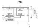
- FIG. 5 is a block diagram showing the lamp lightning device included in the ultraviolet-ray irradiating device of the related art.
- a lamp lighting device 106 in the related art includes a discharge lamp 107 disposed in a channel of an irradiation tube 105 through which ballast water flows, a ballast 111 that lights the discharge lamp 107, and a connection line 114 for feeding a high-frequency AC current from the ballast 111 to the discharge lamp 107.
- the ballast 111 includes a converter section 116 that rectifies an AC current supplied from a power supply and converts the AC current into a DC current and an inverter section 117 that converts the DC current into the high-frequency AC current.
- the ballast 111 includes a control circuit section 121 that controls the converter section 116 and the inverter section 117 and an auxiliary power supply section 122 that supplies electric power to cause the converter section 116 and the inverter section 117 to operate.
- the ballast 111 includes an input terminal section 123 to which the AC current is supplied from the power supply and an output terminal section 128 that supplies the high-frequency AC current to the discharge lamp 107.
- connection line 114 for feeding the high-frequency AC current from the ballast 111 to the discharge lamp 107
- a power loss occurs according to the material and the length of the connection line 114.
- the power loss is reduced by disposing the discharge lamp 107 and the ballast 111 close to each other and reducing the length of the connection line 114.
- the ballast 111 and the power supply cannot be disposed around a position where the discharge lamp 107 is disposed.
- a control room where electronic devices such as a control device including a power board are disposed and a ballast tank in which ballast water is stored is different in each ship.
- the control room and the ballast tank are sometimes disposed apart from each other.
- the discharge lamp which is disposed in the vicinity of the ballast tank
- the ballast which is disposed in the control room
- the length of the connection line is sometimes, for example, approximately 10 m to approximately 100 m.
- connection line for suppressing the occurrence of the power loss.
- a type of a connection line is not limited, when the discharge lamp of the ultraviolet-ray irradiating device is lit with the high-frequency AC current, the connection line for suppressing the occurrence of the power loss is used.
- a special connection line such as a braided cable is used. Since a type of a usable connection line is limited, when the ultraviolet-ray irradiating device is used in the ship, it is difficult to take measures using the connection line for suppressing the occurrence of the power loss.
- connection line and the earth are extremely close to each other because the connection line comes into contact with the floor surface of the like of the ship. A more power loss occurs.
- an object of the present embodiments is to provide a lamp lighting device that can suppress a power loss that occurs in a connection line for feeding a high-frequency AC current to a discharge lamp.
- a lamp lighting device 6 is a lamp lighting device that lights an ultraviolet lamp 7 functioning as a discharge lamp.
- the lamp lighting device 6 includes a first ballast 11, a second ballast 12, first connection lines 13, and second connection lines 14.
- the first ballast 11 includes a converter section 16 functioning as a converter that converts an AC current, which is supplied from a power supply, into a DC current.
- the second ballast 12 includes an inverter section 17 functioning as an inverter that converts the DC current, which is supplied from the first ballast 11, into a high-frequency AC current.
- the first connection lines 13 connect the first ballast 11 and the second ballast 12.
- the first connection lines 13 feed the DC current, which is supplied from the first ballast 11, to the second ballast 12.
- the second connection lines 14 connect the second ballast 12 and the ultraviolet lamp 7.
- the second connection lines 14 feed the high-frequency AC current, which is supplied from the second ballast 12, to the ultraviolet lamp 7.
- the length of the first connection lines 13 is longer than the length of the second connection lines 14 in the lamp lighting device 6 according to the embodiment explained below.
- the second ballast 12 in the lamp lighting device 6, is disposed in the vicinity of an irradiation tube 5 functioning as an irradiating section that irradiates light of the ultraviolet lamp 7 functioning as the discharge lamp on an object to be irradiated.
- the lamp lighting device 6, further includes a plurality of discharge lamps, a plurality of second ballasts 12, and a plurality of second connection lines 14.
- the plurality of second ballasts 12 are connected to the first ballast 11 in parallel.
- the discharge lamp in the lamp lighting device 6, according to the embodiment explained below, is the ultraviolet lamp 7 that radiates an ultraviolet ray.
- the ultraviolet lamp 7 in the lamp lighting device 6, according to the embodiment explained below, is disposed in a channel 10 through which fluid on which the ultraviolet ray is irradiated flows.
- the channel 10 in the lamp lighting device 6, communicates with a ballast tank 4 included in a ship.
- the ultraviolet-ray irradiating device is used for irradiating an ultraviolet ray on ballast water in a ship.
- FIG. 1 is a schematic diagram showing the ultraviolet-ray irradiating device according to the embodiment.
- FIG. 2 is a schematic diagram for explaining an irradiation tube and a lamp lighting device included in the ultraviolet-ray irradiating device according to the embodiment.
- an ultraviolet-ray irradiating device 1 in the embodiment is provided on a supply route of ballast water 3 supplied from the ballast tank 4 that stores the ballast water 3 serving as an object to be irradiated.
- the ultraviolet-ray irradiating device 1 includes the irradiation tube 5 for irradiating an ultraviolet ray on the ballast water 3 and the lamp lighting device 6 that lights the ultraviolet lamp 7 functioning as the discharge lamp.
- the ultraviolet-ray irradiating device 1 includes a first pipe 8a for supplying the ballast water 3, which is supplied from the outside of the ship, to the ultraviolet-ray irradiating device 1.
- the ultraviolet-ray irradiating device 1 includes a second pipe 8b for supplying the ballast water 3 from the ballast tank 4 to the ultraviolet-ray irradiating device 1, a third pipe 8c for returning the ballast water 3 passed through the ultraviolet-ray irradiating device 1 to the ballast tank 4, and a fourth pipe 8d branching from the third pipe 8c to discharge the ballast water 3 from the ship to the outside.
- the first to fourth pipes 8a to 8d communicate with the ballast tank 4. Valves 9 that enable opening and closing of the pipes 8a to 8d are respectively provided in the first to fourth pipes 8a to 8d.
- the irradiation tube 5 of the ultraviolet-ray irradiating device 1 is disposed between the second pipe 8b and the third pipe 8c of the ballast tank 4.
- the irradiation tube 5 includes the channel 10 through which the ballast water 3 supplied from the ballast tank 4 flows.
- a supply port 5a coupled to the second pipe 8b is provided at one end of the irradiation tube 5.
- a discharge port 5b coupled to the third pipe 8c is provided at the other end of the irradiation tube 5.
- FIG. 3 is a block diagram showing the lamp lighting device 6 included in the ultraviolet-ray irradiating device 1 according to the embodiment.
- the lamp lighting device 6 includes the ultraviolet lamp 7, the first ballast 11, the second ballast 12, the first connection lines 13, and the second connection lines 14.
- the lamp lighting device 6 may include a control circuit section 21 and an auxiliary power supply section 22 on the inside of the first ballast 11.
- the lamp lighting device 6 may include a signal line 25.
- pluralities of ultraviolet lamps 7 are disposed in the channel 10 of the irradiation tube 5 at a predetermined interval.
- the ultraviolet lamps 7 are disposed such that center axes 7a of the ultraviolet lamps 7 are orthogonal to a direction in which the ballast water 3 in the channel 10 flows.
- the ultraviolet lamp 7 is a so-called HID (High Intensity Discharge) lamp.
- a mercury lamp is used as the ultraviolet lamp 7.
- the ultraviolet lamp 7 includes an arc tube and a pair of electrodes disposed at both ends of the arc tube. Rare gas and mercury are encapsulated in the arc tube.
- metal halide such as iron iodide may be further encapsulated in the arc tube in addition to the rare gas and the mercury.
- the "ultraviolet ray" is light having a wavelength of 400 nm or less and is, specifically, light having a wavelength of 254 nm or 365 nm that is a bright line of the mercury encapsulated in the arc tube. However, lights having other wavelengths may be the ultraviolet ray.
- the ultraviolet lamp 7 is not limited to an ultraviolet lamp that radiates light having a wavelength of 400 nm or less.
- the ultraviolet lamp 7 may be, for example, an ultraviolet lamp that not only radiates the light having a wavelength of 400 nm or less but also radiates light further on a long wavelength side than 400 nm.
- a light emission form of the ultraviolet lamp 7 is not limited as long as the ultraviolet lamp 7 is an ultraviolet lamp that radiates light having a wavelength of 400 nm or less.
- the disposition of the ultraviolet lamp 7 is not limited to the disposition explained above.
- the tube axis of the ultraviolet lamp 7 may be disposed substantially parallel along the direction in which the ballast water 3 in the channel 10 flows.
- the plurality of ultraviolet lamps 7 disposed in the channel 10 of the irradiation tube 5 are respectively covered by protection tubes 18 having transmittance of an ultraviolet ray.
- the protection tubes 18 are fixed to the inside of the irradiation tube 5. Consequently, the ultraviolet lamps 7 are protected from the ballast water 3 flowing in the irradiation tube 5.
- the first ballast 11 includes the converter section 16 functioning as a converter (an AC/DC converter) that rectifies an AC current supplied from a not-shown power supply and converts the AC current into a DC current.
- the first ballast 11 includes an input terminal section 23 to which the AC current is supplied from the power supply and an output terminal section 24 that supplies the DC current converted by the converter section 16 to the second ballast 12.
- the first ballast 11 includes the control circuit section 21 that controls the converter section 16 and the inverter section 17 explained below and the auxiliary power supply section 22 that supplies an auxiliary AC current to the control circuit section 21 when the supply of the AC current from the power supply stops.
- the second ballast 12 includes the inverter section 17 functioning as an inverter (a DC/AC inverter) that converts the DC current, which is supplied from the first ballast 11, into a high-frequency AC current.
- the second ballast 12 includes an input terminal section 27 to which the DC current is supplied from the first ballast 11 and an output terminal section 28 that supplies the high-frequency AC current converted by the inverter section 17 to the ultraviolet lamp 7.
- the control circuit section 21 is connected to the converter section 16 and the inverter section 17.
- the control circuit section 21 transmits control signals for controlling the converter section 16 and the inverter section 17 to the converter section 16 and the inverter section 17.
- the control circuit section 21 is driven at, for example, DC 24V or DC 5V.
- the auxiliary power supply section 22 is connected to the control circuit section 21 and supplies electric power to the control circuit section 21.
- the auxiliary power supply section 22 supplies a DC current of, for example, DC 24V or DC 5V to the control circuit section 21.
- the first connection lines 13 connect the first ballast 11 and the second ballast 12 and feed the DC current, which is supplied from the first ballast 11, to the second ballast 12.
- the second connection lines 14 connect the second ballast 12 and the ultraviolet lamp 7 and feed the high-frequency AC current, which is supplied from the second ballast 12, to the ultraviolet lamp 7.
- the control circuit section 21 of the first ballast 11 and the inverter section 17 of the second ballast 12 are connected via the signal line 25 for sending a control signal.
- a braided cable obtained by further covering, with a coating material made of metal a plurality of electric wires obtained by covering conductors with an insulation material is used.
- a form of a cable is not limited.
- the first ballast 11 is set in a control room of the ship.
- the second ballast 12 is disposed in the vicinity of the ballast tank 4 away from the control room.
- the second ballast 12 is disposed in the vicinity of the irradiation tube 5 functioning as an irradiating section disposed in the vicinity of the ballast tank 4.
- the vicinity indicates a range of approximately 1 m to 2 m from the irradiation tube 5.
- the first ballast 11 and the second ballast 12 are disposed apart from each other in this way. Therefore, the first connection lines 13 are set relatively long and the second connection lines 14 are set relatively short.
- the length of the first connection lines 13 is set to, for example, approximately 10 m to 100 m.
- the length of the second connection lines 14 is set to, for example, approximately 1 m to 2 m. Therefore, the length of the first connection lines 13 is set longer than the length of the second connection lines 14.
- the lamp lighting device 6 even when the length of the first connection lines 13 for feeding the DC current from the first ballast 11 to the second ballast 12 is set long compared with the length of the second connection lines 14, a power loss hardly occurs.
- the second connection lines 14 for feeding the high-frequency AC current from the second ballast 12 to the ultraviolet lamp 7 a power loss easily occurs compared with the first connection lines 13.
- the second connection lines 14 are set relatively short by setting the first connection lines 13 long. A power loss is suppressed from occurring.
- the high-frequency AC current in this embodiment indicates, for example, an AC current having a frequency of approximately several kilohertz to approximately several ten megahertz.
- the frequency is not particularly limited.
- the first ballast 11 is disposed in the control room and the second ballast 12 is disposed in the vicinity of the ballast tank 4 apart from the control room.
- an AC current of, for example, approximately 400 V is supplied from the power supply to the input terminal section 23 of the first ballast 11.
- the first ballast 11 converts, with the converter section 16, the AC current into a DC current of, for example, approximately 400 V or approximately 700 V.
- the DC current converted by the converter section 16 is output from the output terminal section 24 of the first ballast 11 to the first connection lines 13 and fed by the first connection lines 13.
- the DC current fed by the first connection lines 13 drawn around in the ship is supplied to the input terminal section 27 of the second ballast 12.
- the second ballast 12 converts the DC current supplied to the input terminal section 27 into a high-frequency AC current with the inverter section 17.
- the high-frequency AC current converted by the inverter section 17 is output from the output terminal section 28 of the second ballast 12 to the second connection lines 14 and fed by the second connection lines 14.
- the high-frequency AC current fed by the second connection lines 14 is supplied to the ultraviolet lamp 7 in the irradiation tube 5.
- the ultraviolet lamp 7 is lit.
- the ultraviolet-ray irradiating device 1 is set under an environment in which the control room and the ballast tank 4 are separated in the ship, by setting the second ballast 12 in the vicinity of the ballast tank 4 and extending the first connection lines 13, the length of the second connection lines 14 is minimized. Consequently, it is possible to reduce the length of the second connection lines 14 for feeding the high-frequency AC current. A power loss that occurs when the ultraviolet lamp 7 is lit using the high-frequency AC current is suppressed.
- a power loss of approximately 10% occurs when the high-frequency AC current is fed by the connection line having the length of approximately 10 m to 20 m from the ballast disposed in the control room to the ultraviolet lamp in the irradiation tube disposed in the vicinity of the ballast tank.
- the ship itself can be regarded as an earth. Therefore, when the connection line comes into contact with the floor surface or the like of the ship, the connection line and the earth are extremely close to each other. A more power loss occurs.
- a power loss was able to be suppressed to approximately 0.1% when the high-frequency AC current was fed by the second connection lines 14 having the length of approximately 1 m to 2 m from the second ballast 12 disposed in the vicinity of the ballast tank 4 to the ultraviolet lamp 7 in the irradiation tube 5 disposed in the vicinity of the ballast tank 4. Therefore, according to the embodiment, it is possible to reduce the power loss that occurs when the discharge lamp is lit using the high-frequency AC current to approximately 1/100.
- the lamp lighting device 6 in the embodiment when used in a ship, regarding the ship itself as an earth, even when the connection line comes into contact with the floor surface or the like of the ship and the connection line and the earth are extremely close to each other, it is possible to suppress a power loss.
- the lamp lighting device 6 in the embodiment includes the first ballast 11, the second ballast 12, the first connection lines 13 for feeding the DC current from the first ballast 11 to the second ballast 12, and the second connection lines 14 for feeding the high-frequency AC current from the second ballast 12 to the ultraviolet lamp 7. Consequently, by disposing the second ballast 12 in the vicinity of the ultraviolet lamp 7, it is possible to reduce the length of the second connection lines 14. It is possible to suppress a power loss that occurs in the second connection lines 14 for feeding the high-frequency AC current to the ultraviolet lamp 7.
- the lamp lighting device 6 is suitably used, in particular, as in a small ship, under an environment in which it is difficult to secure a space for setting the entire lamp lighting device 6 in the vicinity of the ballast tank 4.
- the first ballast 11 and the second ballast 12 can be separated. Therefore, the lamp lighting device 6 is suitably used, in particular, as in a small ship, under an environment in which it is difficult to secure a space for setting the lamp lighting device 6 in a power board of the small ship.
- the length of the first connection lines 13 is longer than the length of the second connection lines 14. Consequently, it is possible to suppress a power loss when electric power is supplied from the second ballast 12 to the ultraviolet lamp 7 via the second connection lines 14.
- the second ballast 12 is disposed in the vicinity of the irradiating section 5 that irradiates the light of the ultraviolet lamp 7 on the object to be irradiated. Consequently, it is possible to reduce a power loss that occurs when the ultraviolet lamp 7 is lit using the high-frequency AC current to approximately 1/100.
- the lamp lighting device 6 includes the ultraviolet lamp 7 that radiates an ultraviolet ray. Consequently, it is possible to irradiate the ultraviolet ray on the object to be irradiated and perform treatment such as sterilization of the ballast water 3.
- the ultraviolet-ray irradiating device 1 includes the lamp lighting device 6.
- the ultraviolet lamp 7 irradiates light on the object to be irradiated. Consequently, in particular, in a small ship or the like, it is possible to set the ultraviolet-ray irradiating device 1.
- a lamp lighting device in a modification according to the embodiment is explained below with reference to the drawings. Note that, in the modification, components same as the components in the embodiment are denoted by reference numerals and signs same as the reference numerals and signs in the embodiment. Explanation of the components is omitted.
- FIG. 4 is a block diagram showing a lamp lighting device in a modification.
- the modification is different from the embodiment in that a lamp lighting device 36 includes a plurality of ultraviolet lamps 7 respectively lit by a plurality of second ballasts 12.
- the lamp lighting device 36 in the modification includes the plurality of ultraviolet lamps 7 and the first ballast 11 that converts an AC current supplied from a power supply into a DC current.
- the lamp lighting device 36 includes the plurality of second ballasts 12 that convert the DC current supplied from the first ballast 11 into a high-frequency AC current and respectively light the plurality of ultraviolet lamps 7.
- the plurality of second ballasts 12 are connected to the first ballast 11 in parallel via the first connection lines 13.
- the plurality of ultraviolet lamps 7 are respectively disposed in, for example, different positions of irradiation tubes 5.
- the first connection lines 13 connected to the output terminal section 24 of the first ballast 11 are respectively connected to input terminal sections 27 of the plurality of second ballasts 12.
- signal lines 25 connected to the control circuit section 21 of the first ballast 11 are respectively connected to inverter sections 17 of the plurality of second ballasts 12.
- the plurality of second ballasts 12 are respectively disposed in the irradiation tubes 5 set in different positions.
- first connection lines 13 and the signal lines 25 are divided and shown.
- first ballast 11 and the plurality of second ballasts 12 are individually connected using a plurality of first connection lines 13 and a plurality of signal lines 25.
- the modification as in the embodiment, it is possible to suppress a power loss that occurs in the second connection lines 14 for feeding the high-frequency AC current to the ultraviolet lamps 7. According to the modification, it is possible to use the power supply in common in the plurality of ultraviolet lamps 7 disposed in the different positions of the irradiation tubes 5.
- the first ballast 11 and the plurality of second ballasts 12 are respectively connected via the plurality of first connection lines 13. Therefore, even when the pluralities of second ballasts 12 are set in different positions, it is possible to equalize the lengths of the second connection lines 14 for feeding the high-frequency AC current to the ultraviolet lamps 7. Therefore, it is possible to equalize and stabilize the lighting quality of the plurality of ultraviolet lamps 7.
- this embodiment is applied to the ship.
- this does not limit the ultraviolet-ray irradiating device to the use in the ship.
- the ultraviolet-ray irradiating device is used, for example, when a control room and a treatment room are separated in a contaminated water treatment facility or the like.
- the ultraviolet-ray irradiating device in the embodiment may be applied to, for example, irradiate an ultraviolet ray to soot and smoke. It is desirable that the ultraviolet-ray irradiating device is used when it is difficult to secure a space for disposing the entire lamp lighting device around an irradiation tube as in an exhaust duct to which soot and smoke flows.
Landscapes
- Engineering & Computer Science (AREA)
- Toxicology (AREA)
- Environmental & Geological Engineering (AREA)
- Health & Medical Sciences (AREA)
- Chemical & Material Sciences (AREA)
- Mechanical Engineering (AREA)
- Public Health (AREA)
- Combustion & Propulsion (AREA)
- General Health & Medical Sciences (AREA)
- Ocean & Marine Engineering (AREA)
- Life Sciences & Earth Sciences (AREA)
- Hydrology & Water Resources (AREA)
- Water Supply & Treatment (AREA)
- Organic Chemistry (AREA)
- Physical Water Treatments (AREA)
- Circuit Arrangement For Electric Light Sources In General (AREA)
Abstract
Description
- Exemplary embodiments described herein relate to a lamp lighting device.
- In an ultraviolet-ray irradiating device, a discharge lamp is used in order to irradiate an ultraviolet ray on an object to be irradiated. As the ultraviolet-ray irradiating device of this type, for example, in order to perform treatment such as sterilization of ballast water taken into a ballast tank in a ship, there is an ultraviolet-ray irradiating device used to irradiate an ultraviolet ray on the ballast water serving as an object to be irradiated. In such an ultraviolet-ray irradiating device, for example, a discharge lamp is disposed in a channel through which the ballast water in the ballast tank flows. The discharge lamp is lit using a lamp lighting device.
- In the lamp lighting device of the discharge lamp, there is known a technique for disposing, in a wiring route between the lamp lighting device and the discharge lamp, a starting device that reduces a pulse voltage generated by the lamp lighting device and generating a pulse voltage for starting the discharge lamp.
-
FIG. 5 is a block diagram showing the lamp lightning device included in the ultraviolet-ray irradiating device of the related art. As shown inFIG. 5 , alamp lighting device 106 in the related art includes adischarge lamp 107 disposed in a channel of anirradiation tube 105 through which ballast water flows, aballast 111 that lights thedischarge lamp 107, and aconnection line 114 for feeding a high-frequency AC current from theballast 111 to thedischarge lamp 107. Theballast 111 includes aconverter section 116 that rectifies an AC current supplied from a power supply and converts the AC current into a DC current and aninverter section 117 that converts the DC current into the high-frequency AC current. - The
ballast 111 includes acontrol circuit section 121 that controls theconverter section 116 and theinverter section 117 and an auxiliarypower supply section 122 that supplies electric power to cause theconverter section 116 and theinverter section 117 to operate. Theballast 111 includes aninput terminal section 123 to which the AC current is supplied from the power supply and anoutput terminal section 128 that supplies the high-frequency AC current to thedischarge lamp 107. - Incidentally, when the
discharge lamp 107 is lit at a high frequency as explained above, in theconnection line 114 for feeding the high-frequency AC current from theballast 111 to thedischarge lamp 107, a power loss occurs according to the material and the length of theconnection line 114. The power loss is reduced by disposing thedischarge lamp 107 and theballast 111 close to each other and reducing the length of theconnection line 114. However, there is an environment in which theballast 111 and the power supply cannot be disposed around a position where thedischarge lamp 107 is disposed. - In particular, in a ship, disposition of a control room where electronic devices such as a control device including a power board are disposed and a ballast tank in which ballast water is stored is different in each ship. The control room and the ballast tank are sometimes disposed apart from each other. When the ultraviolet-ray irradiating device is used in such a ship, the discharge lamp, which is disposed in the vicinity of the ballast tank, and the ballast, which is disposed in the control room, are disposed apart from each other. The length of the connection line is sometimes, for example, approximately 10 m to approximately 100 m. When the high-frequency AC current of approximately 3 kW flows to the connection line extended along a structure made of metal of the ship, a power loss of approximately 10% occurs in the connection line.
- As measures against the power loss, it is conceivable to use a connection line for suppressing the occurrence of the power loss. In a general environment in which a type of a connection line is not limited, when the discharge lamp of the ultraviolet-ray irradiating device is lit with the high-frequency AC current, the connection line for suppressing the occurrence of the power loss is used. On the other hand, in the ship, a special connection line such as a braided cable is used. Since a type of a usable connection line is limited, when the ultraviolet-ray irradiating device is used in the ship, it is difficult to take measures using the connection line for suppressing the occurrence of the power loss.
- Further, in the ship, the ship itself can be regarded as an earth. Therefore, the connection line and the earth are extremely close to each other because the connection line comes into contact with the floor surface of the like of the ship. A more power loss occurs.
- Therefore, an object of the present embodiments is to provide a lamp lighting device that can suppress a power loss that occurs in a connection line for feeding a high-frequency AC current to a discharge lamp.
-
-
FIG. 1 is a schematic diagram showing an ultraviolet-ray irradiating device according to an embodiment; -
FIG. 2 is a schematic diagram for explaining an irradiation tube and a lamp lighting device included in the ultraviolet-ray irradiating device; -
FIG. 3 is a block diagram showing the lamp lighting device included in the ultraviolet-ray irradiating device; -
FIG. 4 is a block diagram showing a lamp lighting device according to a modification of the embodiment; and -
FIG. 5 is a block diagram showing a lamp lighting device included in an ultraviolet-ray irradiating device of the related art. - A
lamp lighting device 6 according to an embodiment explained below is a lamp lighting device that lights anultraviolet lamp 7 functioning as a discharge lamp. Thelamp lighting device 6 includes afirst ballast 11, asecond ballast 12,first connection lines 13, andsecond connection lines 14. Thefirst ballast 11 includes aconverter section 16 functioning as a converter that converts an AC current, which is supplied from a power supply, into a DC current. Thesecond ballast 12 includes aninverter section 17 functioning as an inverter that converts the DC current, which is supplied from thefirst ballast 11, into a high-frequency AC current. Thefirst connection lines 13 connect thefirst ballast 11 and thesecond ballast 12. Thefirst connection lines 13 feed the DC current, which is supplied from thefirst ballast 11, to thesecond ballast 12. Thesecond connection lines 14 connect thesecond ballast 12 and theultraviolet lamp 7. Thesecond connection lines 14 feed the high-frequency AC current, which is supplied from thesecond ballast 12, to theultraviolet lamp 7. - The length of the
first connection lines 13 is longer than the length of thesecond connection lines 14 in thelamp lighting device 6 according to the embodiment explained below. - The
second ballast 12 in thelamp lighting device 6, according to the embodiment explained below, is disposed in the vicinity of anirradiation tube 5 functioning as an irradiating section that irradiates light of theultraviolet lamp 7 functioning as the discharge lamp on an object to be irradiated. - The
lamp lighting device 6, according to the embodiment explained below, further includes a plurality of discharge lamps, a plurality ofsecond ballasts 12, and a plurality ofsecond connection lines 14. The plurality ofsecond ballasts 12 are connected to thefirst ballast 11 in parallel. - The discharge lamp in the
lamp lighting device 6, according to the embodiment explained below, is theultraviolet lamp 7 that radiates an ultraviolet ray. - The
ultraviolet lamp 7 in thelamp lighting device 6, according to the embodiment explained below, is disposed in achannel 10 through which fluid on which the ultraviolet ray is irradiated flows. - The
channel 10 in thelamp lighting device 6, according to the embodiment explained below, communicates with aballast tank 4 included in a ship. - An ultraviolet-ray irradiating device according to an embodiment is explained below with reference to the drawings. The ultraviolet-ray irradiating device according to this embodiment is used for irradiating an ultraviolet ray on ballast water in a ship.
-
FIG. 1 is a schematic diagram showing the ultraviolet-ray irradiating device according to the embodiment.FIG. 2 is a schematic diagram for explaining an irradiation tube and a lamp lighting device included in the ultraviolet-ray irradiating device according to the embodiment. As shown inFIGS. 1 and 2 , an ultraviolet-ray irradiatingdevice 1 in the embodiment is provided on a supply route ofballast water 3 supplied from theballast tank 4 that stores theballast water 3 serving as an object to be irradiated. The ultraviolet-ray irradiatingdevice 1 includes theirradiation tube 5 for irradiating an ultraviolet ray on theballast water 3 and thelamp lighting device 6 that lights theultraviolet lamp 7 functioning as the discharge lamp. - As shown in
FIG. 2 , the ultraviolet-ray irradiatingdevice 1 includes afirst pipe 8a for supplying theballast water 3, which is supplied from the outside of the ship, to the ultraviolet-ray irradiatingdevice 1. The ultraviolet-ray irradiatingdevice 1 includes asecond pipe 8b for supplying theballast water 3 from theballast tank 4 to the ultraviolet-ray irradiatingdevice 1, athird pipe 8c for returning theballast water 3 passed through the ultraviolet-ray irradiatingdevice 1 to theballast tank 4, and afourth pipe 8d branching from thethird pipe 8c to discharge theballast water 3 from the ship to the outside. The first tofourth pipes 8a to 8d communicate with theballast tank 4.Valves 9 that enable opening and closing of thepipes 8a to 8d are respectively provided in the first tofourth pipes 8a to 8d. - The
irradiation tube 5 of the ultraviolet-ray irradiatingdevice 1 is disposed between thesecond pipe 8b and thethird pipe 8c of theballast tank 4. Theirradiation tube 5 includes thechannel 10 through which theballast water 3 supplied from theballast tank 4 flows. Asupply port 5a coupled to thesecond pipe 8b is provided at one end of theirradiation tube 5. Adischarge port 5b coupled to thethird pipe 8c is provided at the other end of theirradiation tube 5. -
FIG. 3 is a block diagram showing thelamp lighting device 6 included in the ultraviolet-ray irradiating device 1 according to the embodiment. As shown inFIG. 3 , thelamp lighting device 6 includes theultraviolet lamp 7, thefirst ballast 11, thesecond ballast 12, thefirst connection lines 13, and the second connection lines 14. Note that, as shown inFIG. 3 , thelamp lighting device 6 may include acontrol circuit section 21 and an auxiliarypower supply section 22 on the inside of thefirst ballast 11. As shown inFIG. 3 , thelamp lighting device 6 may include asignal line 25. - As shown in
FIG. 2 , pluralities ofultraviolet lamps 7 are disposed in thechannel 10 of theirradiation tube 5 at a predetermined interval. Theultraviolet lamps 7 are disposed such that center axes 7a of theultraviolet lamps 7 are orthogonal to a direction in which theballast water 3 in thechannel 10 flows. Theultraviolet lamp 7 is a so-called HID (High Intensity Discharge) lamp. For example, a mercury lamp is used as theultraviolet lamp 7. Although not shown in the figure, theultraviolet lamp 7 includes an arc tube and a pair of electrodes disposed at both ends of the arc tube. Rare gas and mercury are encapsulated in the arc tube. - Note that, in the
ultraviolet lamp 7, metal halide such as iron iodide may be further encapsulated in the arc tube in addition to the rare gas and the mercury. The "ultraviolet ray" is light having a wavelength of 400 nm or less and is, specifically, light having a wavelength of 254 nm or 365 nm that is a bright line of the mercury encapsulated in the arc tube. However, lights having other wavelengths may be the ultraviolet ray. Theultraviolet lamp 7 is not limited to an ultraviolet lamp that radiates light having a wavelength of 400 nm or less. Theultraviolet lamp 7 may be, for example, an ultraviolet lamp that not only radiates the light having a wavelength of 400 nm or less but also radiates light further on a long wavelength side than 400 nm. In short, a light emission form of theultraviolet lamp 7 is not limited as long as theultraviolet lamp 7 is an ultraviolet lamp that radiates light having a wavelength of 400 nm or less. The disposition of theultraviolet lamp 7 is not limited to the disposition explained above. For example, the tube axis of theultraviolet lamp 7 may be disposed substantially parallel along the direction in which theballast water 3 in thechannel 10 flows. - The plurality of
ultraviolet lamps 7 disposed in thechannel 10 of theirradiation tube 5 are respectively covered byprotection tubes 18 having transmittance of an ultraviolet ray. Theprotection tubes 18 are fixed to the inside of theirradiation tube 5. Consequently, theultraviolet lamps 7 are protected from theballast water 3 flowing in theirradiation tube 5. - The
first ballast 11 includes theconverter section 16 functioning as a converter (an AC/DC converter) that rectifies an AC current supplied from a not-shown power supply and converts the AC current into a DC current. Thefirst ballast 11 includes aninput terminal section 23 to which the AC current is supplied from the power supply and anoutput terminal section 24 that supplies the DC current converted by theconverter section 16 to thesecond ballast 12. Thefirst ballast 11 includes thecontrol circuit section 21 that controls theconverter section 16 and theinverter section 17 explained below and the auxiliarypower supply section 22 that supplies an auxiliary AC current to thecontrol circuit section 21 when the supply of the AC current from the power supply stops. - The
second ballast 12 includes theinverter section 17 functioning as an inverter (a DC/AC inverter) that converts the DC current, which is supplied from thefirst ballast 11, into a high-frequency AC current. Thesecond ballast 12 includes aninput terminal section 27 to which the DC current is supplied from thefirst ballast 11 and anoutput terminal section 28 that supplies the high-frequency AC current converted by theinverter section 17 to theultraviolet lamp 7. - The
control circuit section 21 is connected to theconverter section 16 and theinverter section 17. Thecontrol circuit section 21 transmits control signals for controlling theconverter section 16 and theinverter section 17 to theconverter section 16 and theinverter section 17. Thecontrol circuit section 21 is driven at, for example, DC 24V or DC 5V. The auxiliarypower supply section 22 is connected to thecontrol circuit section 21 and supplies electric power to thecontrol circuit section 21. The auxiliarypower supply section 22 supplies a DC current of, for example, DC 24V or DC 5V to thecontrol circuit section 21. - The
first connection lines 13 connect thefirst ballast 11 and thesecond ballast 12 and feed the DC current, which is supplied from thefirst ballast 11, to thesecond ballast 12. Thesecond connection lines 14 connect thesecond ballast 12 and theultraviolet lamp 7 and feed the high-frequency AC current, which is supplied from thesecond ballast 12, to theultraviolet lamp 7. Thecontrol circuit section 21 of thefirst ballast 11 and theinverter section 17 of thesecond ballast 12 are connected via thesignal line 25 for sending a control signal. As the first andsecond connection lines signal line 25, a braided cable obtained by further covering, with a coating material made of metal, a plurality of electric wires obtained by covering conductors with an insulation material is used. However, a form of a cable is not limited. - In the
lamp lighting device 6 in the embodiment, thefirst ballast 11 is set in a control room of the ship. Thesecond ballast 12 is disposed in the vicinity of theballast tank 4 away from the control room. In other words, thesecond ballast 12 is disposed in the vicinity of theirradiation tube 5 functioning as an irradiating section disposed in the vicinity of theballast tank 4. The vicinity indicates a range of approximately 1 m to 2 m from theirradiation tube 5. - The
first ballast 11 and thesecond ballast 12 are disposed apart from each other in this way. Therefore, thefirst connection lines 13 are set relatively long and thesecond connection lines 14 are set relatively short. The length of thefirst connection lines 13 is set to, for example, approximately 10 m to 100 m. The length of the second connection lines 14 is set to, for example, approximately 1 m to 2 m. Therefore, the length of thefirst connection lines 13 is set longer than the length of the second connection lines 14. - In the
lamp lighting device 6, even when the length of thefirst connection lines 13 for feeding the DC current from thefirst ballast 11 to thesecond ballast 12 is set long compared with the length of thesecond connection lines 14, a power loss hardly occurs. On the other hand, in thesecond connection lines 14 for feeding the high-frequency AC current from thesecond ballast 12 to theultraviolet lamp 7, a power loss easily occurs compared with the first connection lines 13. However, thesecond connection lines 14 are set relatively short by setting thefirst connection lines 13 long. A power loss is suppressed from occurring. - Note that the high-frequency AC current in this embodiment indicates, for example, an AC current having a frequency of approximately several kilohertz to approximately several ten megahertz. However, the frequency is not particularly limited.
- First, in the
lamp lighting device 6 in the embodiment, as explained above, thefirst ballast 11 is disposed in the control room and thesecond ballast 12 is disposed in the vicinity of theballast tank 4 apart from the control room. In thelamp lighting device 6, an AC current of, for example, approximately 400 V is supplied from the power supply to theinput terminal section 23 of thefirst ballast 11. Thefirst ballast 11 converts, with theconverter section 16, the AC current into a DC current of, for example, approximately 400 V or approximately 700 V. The DC current converted by theconverter section 16 is output from theoutput terminal section 24 of thefirst ballast 11 to thefirst connection lines 13 and fed by the first connection lines 13. The DC current fed by thefirst connection lines 13 drawn around in the ship is supplied to theinput terminal section 27 of thesecond ballast 12. - The
second ballast 12 converts the DC current supplied to theinput terminal section 27 into a high-frequency AC current with theinverter section 17. The high-frequency AC current converted by theinverter section 17 is output from theoutput terminal section 28 of thesecond ballast 12 to thesecond connection lines 14 and fed by the second connection lines 14. The high-frequency AC current fed by the second connection lines 14 is supplied to theultraviolet lamp 7 in theirradiation tube 5. Theultraviolet lamp 7 is lit. - Even when the ultraviolet-
ray irradiating device 1 is set under an environment in which the control room and theballast tank 4 are separated in the ship, by setting thesecond ballast 12 in the vicinity of theballast tank 4 and extending thefirst connection lines 13, the length of the second connection lines 14 is minimized. Consequently, it is possible to reduce the length of thesecond connection lines 14 for feeding the high-frequency AC current. A power loss that occurs when theultraviolet lamp 7 is lit using the high-frequency AC current is suppressed. - Note that, as the distance between the
second ballast 12 and theultraviolet lamp 7 increases, the length of thesecond connection lines 14, which connect thesecond ballast 12 and theultraviolet lamp 7, increases. Therefore, a power loss, that occurs when the high-frequency AC current is fed, increases. However, an effect is sufficiently obtained compared with the lamp lighting device of the related art. - In the lamp lighting device of the related art, a power loss of approximately 10% occurs when the high-frequency AC current is fed by the connection line having the length of approximately 10 m to 20 m from the ballast disposed in the control room to the ultraviolet lamp in the irradiation tube disposed in the vicinity of the ballast tank.
- When the lamp lighting device of the related art is used in a ship, the ship itself can be regarded as an earth. Therefore, when the connection line comes into contact with the floor surface or the like of the ship, the connection line and the earth are extremely close to each other. A more power loss occurs.
- In contrast, in the
lamp lighting device 6 in the embodiment, a power loss was able to be suppressed to approximately 0.1% when the high-frequency AC current was fed by thesecond connection lines 14 having the length of approximately 1 m to 2 m from thesecond ballast 12 disposed in the vicinity of theballast tank 4 to theultraviolet lamp 7 in theirradiation tube 5 disposed in the vicinity of theballast tank 4. Therefore, according to the embodiment, it is possible to reduce the power loss that occurs when the discharge lamp is lit using the high-frequency AC current to approximately 1/100. - Further, when the
lamp lighting device 6 in the embodiment is used in a ship, regarding the ship itself as an earth, even when the connection line comes into contact with the floor surface or the like of the ship and the connection line and the earth are extremely close to each other, it is possible to suppress a power loss. - The
lamp lighting device 6 in the embodiment includes thefirst ballast 11, thesecond ballast 12, thefirst connection lines 13 for feeding the DC current from thefirst ballast 11 to thesecond ballast 12, and thesecond connection lines 14 for feeding the high-frequency AC current from thesecond ballast 12 to theultraviolet lamp 7. Consequently, by disposing thesecond ballast 12 in the vicinity of theultraviolet lamp 7, it is possible to reduce the length of the second connection lines 14. It is possible to suppress a power loss that occurs in thesecond connection lines 14 for feeding the high-frequency AC current to theultraviolet lamp 7. - According to the embodiment, only the
second ballast 12 has to be disposed in the vicinity of theballast tank 4. Therefore, thelamp lighting device 6 is suitably used, in particular, as in a small ship, under an environment in which it is difficult to secure a space for setting the entirelamp lighting device 6 in the vicinity of theballast tank 4. - According to the embodiment, the
first ballast 11 and thesecond ballast 12 can be separated. Therefore, thelamp lighting device 6 is suitably used, in particular, as in a small ship, under an environment in which it is difficult to secure a space for setting thelamp lighting device 6 in a power board of the small ship. - According to the embodiment, the length of the
first connection lines 13 is longer than the length of the second connection lines 14. Consequently, it is possible to suppress a power loss when electric power is supplied from thesecond ballast 12 to theultraviolet lamp 7 via the second connection lines 14. - According to the embodiment, the
second ballast 12 is disposed in the vicinity of theirradiating section 5 that irradiates the light of theultraviolet lamp 7 on the object to be irradiated. Consequently, it is possible to reduce a power loss that occurs when theultraviolet lamp 7 is lit using the high-frequency AC current to approximately 1/100. - According to the embodiment, the
lamp lighting device 6 includes theultraviolet lamp 7 that radiates an ultraviolet ray. Consequently, it is possible to irradiate the ultraviolet ray on the object to be irradiated and perform treatment such as sterilization of theballast water 3. - According to the embodiment, the ultraviolet-
ray irradiating device 1 includes thelamp lighting device 6. Theultraviolet lamp 7 irradiates light on the object to be irradiated. Consequently, in particular, in a small ship or the like, it is possible to set the ultraviolet-ray irradiating device 1. - A lamp lighting device in a modification according to the embodiment is explained below with reference to the drawings. Note that, in the modification, components same as the components in the embodiment are denoted by reference numerals and signs same as the reference numerals and signs in the embodiment. Explanation of the components is omitted.
-
FIG. 4 is a block diagram showing a lamp lighting device in a modification. The modification is different from the embodiment in that alamp lighting device 36 includes a plurality ofultraviolet lamps 7 respectively lit by a plurality ofsecond ballasts 12. - As shown in
FIG. 4 , thelamp lighting device 36 in the modification includes the plurality ofultraviolet lamps 7 and thefirst ballast 11 that converts an AC current supplied from a power supply into a DC current. Thelamp lighting device 36 includes the plurality ofsecond ballasts 12 that convert the DC current supplied from thefirst ballast 11 into a high-frequency AC current and respectively light the plurality ofultraviolet lamps 7. The plurality ofsecond ballasts 12 are connected to thefirst ballast 11 in parallel via the first connection lines 13. - The plurality of
ultraviolet lamps 7 are respectively disposed in, for example, different positions ofirradiation tubes 5. Thefirst connection lines 13 connected to theoutput terminal section 24 of thefirst ballast 11 are respectively connected to inputterminal sections 27 of the plurality ofsecond ballasts 12. Similarly,signal lines 25 connected to thecontrol circuit section 21 of thefirst ballast 11 are respectively connected toinverter sections 17 of the plurality ofsecond ballasts 12. The plurality ofsecond ballasts 12 are respectively disposed in theirradiation tubes 5 set in different positions. - Note that, in
FIG. 4 , for convenience of illustration, thefirst connection lines 13 and thesignal lines 25 are divided and shown. However, thefirst ballast 11 and the plurality ofsecond ballasts 12 are individually connected using a plurality offirst connection lines 13 and a plurality of signal lines 25. - In the modification, as in the embodiment, it is possible to suppress a power loss that occurs in the
second connection lines 14 for feeding the high-frequency AC current to theultraviolet lamps 7. According to the modification, it is possible to use the power supply in common in the plurality ofultraviolet lamps 7 disposed in the different positions of theirradiation tubes 5. - The
first ballast 11 and the plurality ofsecond ballasts 12 are respectively connected via the plurality of first connection lines 13. Therefore, even when the pluralities ofsecond ballasts 12 are set in different positions, it is possible to equalize the lengths of thesecond connection lines 14 for feeding the high-frequency AC current to theultraviolet lamps 7. Therefore, it is possible to equalize and stabilize the lighting quality of the plurality ofultraviolet lamps 7. - Note that this embodiment is applied to the ship. However, this does not limit the ultraviolet-ray irradiating device to the use in the ship. For example, it is desirable that the ultraviolet-ray irradiating device is used, for example, when a control room and a treatment room are separated in a contaminated water treatment facility or the like.
- The ultraviolet-ray irradiating device in the embodiment may be applied to, for example, irradiate an ultraviolet ray to soot and smoke. It is desirable that the ultraviolet-ray irradiating device is used when it is difficult to secure a space for disposing the entire lamp lighting device around an irradiation tube as in an exhaust duct to which soot and smoke flows.
- While certain embodiments have been described, these embodiments have been presented by way of example only, and are not intended to limit the scope of the inventions. Indeed, the novel embodiments described herein may be embodied in a variety of other forms; furthermore, various omissions, substitutions and changes in the form of the embodiments described herein may be made without departing from the spirit of the inventions. The accompanying claims and their equivalents are intended to cover such forms or modifications as would fall within the scope and spirit of the inventions.
Claims (7)
- A lamp lighting device that lights a discharge lamp, the lamp lighting device comprising:a first ballast including a converter that converts an AC current, which is supplied from a power supply, into a DC current;a second ballast including an inverter that converts the DC current, which is supplied from the first ballast, into a high-frequency AC current;a first connection line that connects the first ballast and the second ballast and that feeds the DC current, which is supplied from the first ballast, to the second ballast; anda second connection line that connects the second ballast and the discharge lamp and that feeds the high-frequency AC current, which is supplied from the second ballast, to the discharge lamp.
- The lamp lighting device according to claim 1, wherein length of the first connection line is longer than length of the second connection line.
- The lamp lighting device according to claim 1 or 2, wherein the second ballast is disposed in a vicinity of an irradiating section that irradiates light of the discharge lamp on an object to be irradiated.
- The lamp lighting device according to any one of claims 1 to 3, further comprising:a plurality of the discharge lamps;a plurality of the second ballasts; anda plurality of the second connection lines, whereinthe plurality of second ballasts are connected to the first ballast in parallel.
- The lamp lighting device according to any one of claims 1 to 4, wherein the discharge lamp is an ultraviolet lamp that radiates an ultraviolet ray.
- The lamp lighting device according to claim 5, wherein the discharge lamp is disposed in a channel through which fluid, on which an ultraviolet ray is irradiated, flows.
- The lamp lighting device according to claim 6, wherein the channel communicates with a ballast tank included in a ship.
Applications Claiming Priority (1)
| Application Number | Priority Date | Filing Date | Title |
|---|---|---|---|
| JP2015149909A JP2017033670A (en) | 2015-07-29 | 2015-07-29 | Lamp lighting device and irradiation device |
Publications (1)
| Publication Number | Publication Date |
|---|---|
| EP3125654A1 true EP3125654A1 (en) | 2017-02-01 |
Family
ID=56507457
Family Applications (1)
| Application Number | Title | Priority Date | Filing Date |
|---|---|---|---|
| EP16180534.6A Withdrawn EP3125654A1 (en) | 2015-07-29 | 2016-07-21 | Lamp lighting device |
Country Status (4)
| Country | Link |
|---|---|
| EP (1) | EP3125654A1 (en) |
| JP (1) | JP2017033670A (en) |
| CN (1) | CN205864825U (en) |
| TW (1) | TW201705822A (en) |
Families Citing this family (1)
| Publication number | Priority date | Publication date | Assignee | Title |
|---|---|---|---|---|
| JP7247580B2 (en) * | 2018-12-27 | 2023-03-29 | 東芝ライテック株式会社 | UV irradiation device |
Citations (1)
| Publication number | Priority date | Publication date | Assignee | Title |
|---|---|---|---|---|
| US4751398A (en) * | 1986-03-18 | 1988-06-14 | The Bodine Company | Lighting system for normal and emergency operation of high intensity discharge lamps |
Family Cites Families (3)
| Publication number | Priority date | Publication date | Assignee | Title |
|---|---|---|---|---|
| JP2001338786A (en) * | 2000-05-29 | 2001-12-07 | Kinden Corp | Fluorescent lighting device |
| EP1810551A1 (en) * | 2004-11-04 | 2007-07-25 | Koninklijke Philips Electronics N.V. | Electronic ballast with remote capacitor placement |
| JP4138797B2 (en) * | 2005-11-25 | 2008-08-27 | 株式会社荏原製作所 | UV irradiation equipment |
-
2015
- 2015-07-29 JP JP2015149909A patent/JP2017033670A/en active Pending
-
2016
- 2016-07-21 EP EP16180534.6A patent/EP3125654A1/en not_active Withdrawn
- 2016-07-28 CN CN201620805099.7U patent/CN205864825U/en not_active Expired - Fee Related
- 2016-07-28 TW TW105123869A patent/TW201705822A/en unknown
Patent Citations (1)
| Publication number | Priority date | Publication date | Assignee | Title |
|---|---|---|---|---|
| US4751398A (en) * | 1986-03-18 | 1988-06-14 | The Bodine Company | Lighting system for normal and emergency operation of high intensity discharge lamps |
Also Published As
| Publication number | Publication date |
|---|---|
| TW201705822A (en) | 2017-02-01 |
| JP2017033670A (en) | 2017-02-09 |
| CN205864825U (en) | 2017-01-04 |
Similar Documents
| Publication | Publication Date | Title |
|---|---|---|
| CN101379586B (en) | Low-pressure mercury vapor discharge lamp with amalgam | |
| TW200742495A (en) | Lamp lighting apparatus | |
| JPH11503265A (en) | Method and apparatus for ionizing illumination with DC pulses | |
| CN205864825U (en) | Lamp igniting device and irradiation unit | |
| JP4897696B2 (en) | Ballast and lamp combination with optional integrated cooling circuit | |
| CN101514783B (en) | Ultraviolet irradiation apparatus | |
| JP2020512191A (en) | Device for irradiating a flowing medium with UV radiation | |
| US6356039B2 (en) | Modular electronic supply device for discharge lamp | |
| ES2272713T3 (en) | ADAPTATION DEVICE FOR UV EMISSORS, AS WELL AS PROCEDURE AND DEVICE FOR WATER DISINFECTION. | |
| KR100840798B1 (en) | Short arc type discharge lamp lighting device, ultraviolet light irradiation device and ultraviolet light irradiation method | |
| JP2017225951A (en) | Ultraviolet irradiation device | |
| CN211925695U (en) | Lighting device | |
| US11363691B2 (en) | Driver incorporating a lighting ballast for supplying constant voltage loads | |
| US9334177B1 (en) | Coreless transformer UV light source system | |
| JP2013232355A (en) | Illuminating device | |
| JP2017120727A (en) | Discharge lamp lighting device | |
| JP2005183320A (en) | Lighting device | |
| KR101727548B1 (en) | Power supply device and method for generating a trigger of High-Energy Laser System | |
| JP3939388B2 (en) | Electrodeless discharge lamp device, electrodeless discharge lamp lighting device, and fluid treatment device | |
| KR20250108692A (en) | Coaxial Microwave Plasma Torch | |
| CN105813360A (en) | Hierarchical control ballast | |
| JPH0924090A (en) | Electronic ballast for ultraviolet irradiation unit | |
| JP2017016869A (en) | Lamp lighting device, irradiation device, and lamp lighting method | |
| CN105744708A (en) | Hierarchical control type ballast | |
| NL1035267C1 (en) | Trouble-free adjustable converging power obtaining apparatus, has capacitor and resistor for transforming low frequency alternating current voltage equal to stabilization voltage |
Legal Events
| Date | Code | Title | Description |
|---|---|---|---|
| PUAI | Public reference made under article 153(3) epc to a published international application that has entered the european phase |
Free format text: ORIGINAL CODE: 0009012 |
|
| AK | Designated contracting states |
Kind code of ref document: A1 Designated state(s): AL AT BE BG CH CY CZ DE DK EE ES FI FR GB GR HR HU IE IS IT LI LT LU LV MC MK MT NL NO PL PT RO RS SE SI SK SM TR |
|
| AX | Request for extension of the european patent |
Extension state: BA ME |
|
| 17P | Request for examination filed |
Effective date: 20170607 |
|
| RBV | Designated contracting states (corrected) |
Designated state(s): AL AT BE BG CH CY CZ DE DK EE ES FI FR GB GR HR HU IE IS IT LI LT LU LV MC MK MT NL NO PL PT RO RS SE SI SK SM TR |
|
| 17Q | First examination report despatched |
Effective date: 20180821 |
|
| STAA | Information on the status of an ep patent application or granted ep patent |
Free format text: STATUS: THE APPLICATION IS DEEMED TO BE WITHDRAWN |
|
| 18D | Application deemed to be withdrawn |
Effective date: 20190103 |