EP3125614A1 - System and method for selecting a communication network in a sensor network - Google Patents
System and method for selecting a communication network in a sensor network Download PDFInfo
- Publication number
- EP3125614A1 EP3125614A1 EP16174010.5A EP16174010A EP3125614A1 EP 3125614 A1 EP3125614 A1 EP 3125614A1 EP 16174010 A EP16174010 A EP 16174010A EP 3125614 A1 EP3125614 A1 EP 3125614A1
- Authority
- EP
- European Patent Office
- Prior art keywords
- network
- stack
- sensor
- power line
- control module
- Prior art date
- Legal status (The legal status is an assumption and is not a legal conclusion. Google has not performed a legal analysis and makes no representation as to the accuracy of the status listed.)
- Granted
Links
Images

Classifications
-
- H—ELECTRICITY
- H04—ELECTRIC COMMUNICATION TECHNIQUE
- H04B—TRANSMISSION
- H04B3/00—Line transmission systems
- H04B3/54—Systems for transmission via power distribution lines
- H04B3/544—Setting up communications; Call and signalling arrangements
-
- H—ELECTRICITY
- H04—ELECTRIC COMMUNICATION TECHNIQUE
- H04L—TRANSMISSION OF DIGITAL INFORMATION, e.g. TELEGRAPHIC COMMUNICATION
- H04L69/00—Network arrangements, protocols or services independent of the application payload and not provided for in the other groups of this subclass
- H04L69/18—Multiprotocol handlers, e.g. single devices capable of handling multiple protocols
-
- G—PHYSICS
- G08—SIGNALLING
- G08C—TRANSMISSION SYSTEMS FOR MEASURED VALUES, CONTROL OR SIMILAR SIGNALS
- G08C17/00—Arrangements for transmitting signals characterised by the use of a wireless electrical link
- G08C17/02—Arrangements for transmitting signals characterised by the use of a wireless electrical link using a radio link
-
- H—ELECTRICITY
- H04—ELECTRIC COMMUNICATION TECHNIQUE
- H04B—TRANSMISSION
- H04B3/00—Line transmission systems
- H04B3/54—Systems for transmission via power distribution lines
-
- H—ELECTRICITY
- H04—ELECTRIC COMMUNICATION TECHNIQUE
- H04L—TRANSMISSION OF DIGITAL INFORMATION, e.g. TELEGRAPHIC COMMUNICATION
- H04L41/00—Arrangements for maintenance, administration or management of data switching networks, e.g. of packet switching networks
- H04L41/08—Configuration management of networks or network elements
- H04L41/085—Retrieval of network configuration; Tracking network configuration history
- H04L41/0853—Retrieval of network configuration; Tracking network configuration history by actively collecting configuration information or by backing up configuration information
- H04L41/0856—Retrieval of network configuration; Tracking network configuration history by actively collecting configuration information or by backing up configuration information by backing up or archiving configuration information
-
- H—ELECTRICITY
- H04—ELECTRIC COMMUNICATION TECHNIQUE
- H04W—WIRELESS COMMUNICATION NETWORKS
- H04W48/00—Access restriction; Network selection; Access point selection
- H04W48/18—Selecting a network or a communication service
-
- H—ELECTRICITY
- H04—ELECTRIC COMMUNICATION TECHNIQUE
- H04L—TRANSMISSION OF DIGITAL INFORMATION, e.g. TELEGRAPHIC COMMUNICATION
- H04L67/00—Network arrangements or protocols for supporting network services or applications
- H04L67/01—Protocols
- H04L67/12—Protocols specially adapted for proprietary or special-purpose networking environments, e.g. medical networks, sensor networks, networks in vehicles or remote metering networks
-
- H—ELECTRICITY
- H04—ELECTRIC COMMUNICATION TECHNIQUE
- H04W—WIRELESS COMMUNICATION NETWORKS
- H04W4/00—Services specially adapted for wireless communication networks; Facilities therefor
- H04W4/70—Services for machine-to-machine communication [M2M] or machine type communication [MTC]
-
- H—ELECTRICITY
- H04—ELECTRIC COMMUNICATION TECHNIQUE
- H04W—WIRELESS COMMUNICATION NETWORKS
- H04W84/00—Network topologies
- H04W84/18—Self-organising networks, e.g. ad-hoc networks or sensor networks
-
- H—ELECTRICITY
- H04—ELECTRIC COMMUNICATION TECHNIQUE
- H04W—WIRELESS COMMUNICATION NETWORKS
- H04W88/00—Devices specially adapted for wireless communication networks, e.g. terminals, base stations or access point devices
- H04W88/02—Terminal devices
- H04W88/06—Terminal devices adapted for operation in multiple networks or having at least two operational modes, e.g. multi-mode terminals
-
- Y—GENERAL TAGGING OF NEW TECHNOLOGICAL DEVELOPMENTS; GENERAL TAGGING OF CROSS-SECTIONAL TECHNOLOGIES SPANNING OVER SEVERAL SECTIONS OF THE IPC; TECHNICAL SUBJECTS COVERED BY FORMER USPC CROSS-REFERENCE ART COLLECTIONS [XRACs] AND DIGESTS
- Y04—INFORMATION OR COMMUNICATION TECHNOLOGIES HAVING AN IMPACT ON OTHER TECHNOLOGY AREAS
- Y04S—SYSTEMS INTEGRATING TECHNOLOGIES RELATED TO POWER NETWORK OPERATION, COMMUNICATION OR INFORMATION TECHNOLOGIES FOR IMPROVING THE ELECTRICAL POWER GENERATION, TRANSMISSION, DISTRIBUTION, MANAGEMENT OR USAGE, i.e. SMART GRIDS
- Y04S40/00—Systems for electrical power generation, transmission, distribution or end-user application management characterised by the use of communication or information technologies, or communication or information technology specific aspects supporting them
- Y04S40/18—Network protocols supporting networked applications, e.g. including control of end-device applications over a network
Definitions
- the disclosed system relates to a flexible network system for an aircraft and, more particularly, to a system and method for selecting either a first sensor network based on a wireless communication protocol or a second sensor network based on a power line communication protocol.
- An aircraft may include various of sensors for flight control and various operations.
- the sensors may be part of an aircraft sensor network for sending data collected by the sensors to computing systems that may analyze the data collected by the sensors.
- an environmental control system for a passenger cabin in an aircraft may use various temperature sensors and airflow sensors to identify changes that may be needed to maintain a desired environment in the passenger cabin.
- a wireless sensor network may be used.
- Some examples of the issues encountered when attempting to implement a wireless network within an aircraft include, for example, power and battery constraints, radio frequency (RF) channel impairments, security, and physical to logical mapping.
- RF radio frequency
- existing wireless solutions are not always secure when subjected to interference due to the inherent nature of wireless mediums.
- accurate physical to logical mapping of wireless nodes may not be accomplished unless there is a high amount of bandwidth available.
- a sensor network in one aspect, includes a first network based on a wireless communication protocol, a second network based on a power line communication protocol, and at least one sensor node in communication with one of the first network and the second network.
- the sensor node includes at least one sensor and a control module in communication with the at least one sensor.
- the control module includes control logic for selecting one of the first network and the second network based on at least one operating parameter of the sensor network.
- a method of selecting one of a first network and a second network within a sensor network of an aircraft includes detecting, by a control module, at least one operating parameter of the sensor network. The method also includes selecting, by the control module, one of the first network and the second network based on the at least one operating parameter of the sensor network.
- the first network is based on a wireless communication protocol
- the second network is based on a power line communication protocol
- the control module is part of at least one sensor node in communication with one of the first network and the second network.
- FIG. 1 is a block diagram illustrating the disclosed sensor network 10.
- the sensor network 10 may include one or more sensor nodes 20 (which may also be referred to as motes), a data concentrator 22, and a server 24.
- the sensor network 10 may be a hybrid network that includes two different communication protocols for transmitting data collected by the sensor nodes 20 to the server 24.
- the sensor network 10 provides a robust, flexible network for communicating data gathered by the sensor nodes 20 using either a wireless network or a power line communication.
- the sensor network 10 may easily switch over to the remaining network for uninterrupted data communication service.
- the sensor network 10 is part of an aircraft 26.
- the sensor network 10 is not limited to an aircraft 26 and may be used in other environments as well such as, for example, automotive applications.
- the aircraft 26 is not intended to be limiting in nature, it should be appreciated that aircraft networks generally do not require relatively fast data transmission rates. Therefore, as explained below, the wireless medium as well as a power line communication may each be based on a communication protocol having relatively low data transmission rates.
- Each of the sensor nodes 20 may include a respective antenna 30, and each sensor node 20 may be in communication with the remaining sensor nodes 20 as well as the data concentrator 22 through a wireless connection 32.
- the wireless connection 32 may be based on a radio frequency (RF) communication protocol.
- the wireless connection 32 may be based on a RF communication protocol having a relatively low data transmission rate with a transmission rate on the order of hundreds of kilobytes/second.
- RF communication protocol having a relatively low data rate is a communication protocol based on the Institute of Electrical and Electronics Engineers (IEEE) 802.15.4 protocol.
- the IEEE 802.15.4 protocol only defines the lower network layers of a seven-layer Open Systems Interconnect (OSI) model, such as a physical (PHY) layer as well as a media access control (MAC) layer.
- the PHY layer may be referred to as layer 1, and is the lowest layer in the network layers.
- the MAC layer may be referred to as layer 2.
- higher-level layers are not defined by the IEEE 802.15.4 protocol.
- wireless communication protocols that are based on the IEEE 802.15.4 protocol include, but are not limited to, ZigBee®, WirelessHART®, and 6LoWPAN.
- Each of the sensor nodes 20 may be in communication with one another as well as the data concentrator 22 and the server 24 through a power line communication 38.
- the power line communication 38 may also be based on a communication protocol having relative low data transmission rates such as, for example, narrow-band power line communications.
- the power line communication 38 may be based on the IEEE 1901.2 protocol. It is to be understood that a narrow-band power line communication typically operates at frequency bands below about 500 kiloHertz (kHz). It is to be appreciated that the power line communication 38 should not be limited to only narrow-band power line communication, however, narrow-band communication may provide reduced interference with other system located on the aircraft 26.
- the power line communication 38 may utilize either existing alternating current (AC) or direct current (DC) power lines within the aircraft 26, which in turn reduces the cost and weight of the aircraft 26.
- the power line communication 38 may utilize an existing 115 VAC line, or an existing 28 VDC line within the aircraft 26.
- the sensor nodes 20 may include one or more sensors (not illustrated) for gathering sensory information indicative of operating conditions within the aircraft 26 such as, for example, temperature, pressure, speed, and altitude.
- the sensor nodes 20 may also process the sensory information gathered by the sensors by a respective control module 40.
- the control module 40 may both refer to, or be part of, an application specific integrated circuit (ASIC), an electronic circuit, a combinational logic circuit, a field programmable gate array (FPGA), a processor (shared, dedicated, or group) comprising hardware or software that executes code, or a combination of some or all of the above, such as in a system-on-chip.
- ASIC application specific integrated circuit
- FPGA field programmable gate array
- the control module 40 may include multiple stack configurations saved in memory for communication with both the wireless connection 32 and the power line communication 38, which is explained in greater detail below and is illustrated in FIG. 3 .
- the sensor nodes 20 may transmit data indicative of the operating conditions detected by the sensors to other sensor nodes 20 within the sensor network 10, as well as to the data concentrator 22 through either the wireless connection 32 or the power line communication 38.
- the data concentrator 22 may include an antenna 42.
- the wireless connection 32 connects the sensor nodes 20 to the data concentrator 22 through the respective antennas 30, 42.
- the data concentrator 22 may collect the data from the sensor nodes 20, and may transmit the data received from the sensor nodes 20 to the server 24 over a data connection 44.
- the connection 44 may be any type of connection for transmitting data such as, for example, an Ethernet connection.
- the data concentrator 22 may include at least one control module 50 for transmitting the data received from the sensor nodes 20 to the server 24.
- the control module 50 may include multiple stack configurations saved in memory for communication with both the wireless connection 32 and the power line communication 38, which is explained in greater detail below and is illustrated in FIG. 3 . Both the control modules 40 and the control module 50 may include control logic for selecting communication based on either the wireless connection 32 or the power line communication 38.
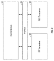
- FIG. 2 is a block diagram of the control module 50 in communication with two transceivers 60, 62 through an interface 64.
- one of the transceivers 60 is an RF transceiver that is in communication with the wireless connection 32 ( FIG. 1 ).
- the RF transceiver 60 is for sending and receiving communication from the wireless connection 32.
- the remaining transceiver 62 may be a power line communication (PLC) transceiver that is in communication with the power line communication 38 ( FIG. 1 ).
- the PLC transceiver 62 is for sending and receiving communication from the power line communication 38.
- PLC power line communication
- Both the RF transceiver 60 and the PLC transceiver 62 are both in communication with the interface 64.
- the interface 64 may be, for example, an enhanced serial peripheral interface (SPI) based on the IEEE 802.15.4 protocol. It should be appreciated that the SPI interface is common between both the RF transceiver 60 and the PLC transceiver 62.
- the interface 64 may transmit communication from the RF transceiver 60 and the PLC transceiver 62 to the control module 50.
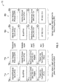
- FIG. 3 is an exemplary network stack configuration 70 saved within memory of the control module 50 ( FIGS. 1 and 2 ), as well as within a memory of the control modules 40 (shown in FIG. 1 ).
- the stack 70 includes a first, power line communication stack 71 and a second, wireless connection stack 80.
- the power line communication stack 71 may include one or more stack options for communication with the PLC transceiver 62 shown in FIG. 2 .
- the power line communication stack 71 includes two stacks 71a, 71b that are each based on the OSI model.
- this illustration is not limiting, and in another embodiment the network stack configuration 70 may be based on another protocol as well such as Zigbee Stack®.
- FIG. 3 illustrates the power line communication stack 71a including a plurality of layers, namely a PHY layer 72a, a MAC layer 74a, a network layer 76a, and a transport layer 78a.
- the power line communication stack 71b is shown including a PHY layer 72b, a MAC layer 74b, a network layer 76b, and a transport layer 78b.
- the top three layers of the two stacks 71a, 71b namely the session layer, the presentation layer, and the application layer, are not illustrated in FIG. 3 for purposes of simplicity and clarity.
- the power line communication stacks 71a, 71b both include these layers.
- the PHY layers 72a, 72b may receive and transmit messages to and from a physical medium.
- the physical medium may be a sensor modules (not illustrated) of the sensor nodes 20 shown in FIG. 1 , if the network stack configuration 70 is saved within memory of the control module 40.
- the physical device may also be the PLC transceiver 62 ( FIG. 2 ), if the network stack configuration 70 is saved within memory of the control module 50.
- the MAC layers 74a, 74b may act as an interface between the network layers 76a, 76b and the PHY layers 72a, 72b. As can be seen in FIG. 3 , the MAC layers 74a, 74b are both adapted to the IEEE 802.15.4 protocol.
- the IEEE 802.15.4 protocol is not intended for power line communication.
- the MAC layers 74a, 74b have been adapted or modified in order for power line communication.
- the network layers 76a, 76b and the transport layers 78a, 78b may be considered higher layers than the PHY layer 72 and the MAC layer 74, as data from the PLC transceiver 62 may travel up through the stack, from the respective PHY layers 72a, 72b to the application layer (not illustrated).
- the data may then be sent over the power line communication 38, if the network stack configuration 70 is saved within memory of the control module 40. If the network stack configuration 70 is saved within memory of the control module 50, then data may be sent over the connection 44 and to the server 24 ( FIG. 1 ).
- the network layer 76a may be provided for communication based on the 6LoWPAN protocol. Specifically, the network layer 76a may send data packets based on Internet Protocol version 6 (IPv6) to the transport layer 78a. Likewise, the network layer 76b may be provided or communication based on Internet Protocol version 4 (IPv4). The network layer 76b may send data packets based on the User Datagram Protocol (UDP) to the transport layer 78b.
- IPv6 Internet Protocol version 6
- IPv4 Internet Protocol version 4
- UDP User Datagram Protocol
- FIG. 3 is merely exemplary in nature, and that the network layers 76a, 76b and the transport layers 78a, 78b may be based on another protocol as well.
- the power line communication stack 71 includes two stacks 71a, 71b, this illustration is merely exemplary in nature, and any number of stacks for accommodating other types of communication protocols may be included as well.
- the wireless connection stack 80 may include one or more stack options for communication with the RF transceiver 60 shown in FIG. 2 .
- the wireless connection stack 80 includes two stacks 80a, 80b.
- FIG. 3 illustrates the wireless connection stack 80a including a PHY layer 82a, a MAC layer 84a, a network layer 86a, and a transport layer 88a.
- FIG. 3 illustrates the wireless connection stack 80b including a PHY layer 82b, a MAC layer 84b, a network layer 86b, and a transport layer 88b.
- the top three layers of the two stacks 80a, 80b namely the session layer, the presentation layer, and the application layer, are also not illustrated in FIG. 3 for purposes of simplicity and clarity.
- the PHY layers 82a, 82b may receive and transmit messages to and from a physical device.
- the physical device may be the sensors (not illustrated) of the sensor nodes 20 shown in FIG. 1 , if the network stack configuration 70 is saved within memory of the control module 40.
- the physical device may also be the RF transceiver 60 ( FIG. 2 ), if the network stack configuration 70 is saved within memory of the control module 50.
- the network layer 86a of the wireless connection stack 80a may be provided for communication based on 6LoWPAN.
- the network layer 86b of the wireless connection stack 80b may be based on IPv4.
- both the control modules 40, 50 may each include control logic for selecting either the power line communication stack 71 or the wireless connection stack 80 of the network stack configuration 70.
- the selection of the specific stack may be based on at least one operating parameter of the sensor network 10. Specifically, the selection of the specific stack may be based on if one or more layers (i.e., the PHY layer, the MAC layer, the network layer, the transport layer, the session layer, the presentation layer, and the application layer) of the network stack configuration 70 are unavailable.
- the wireless connection stack 80 may be a default stack that is utilized unless the wireless connection 32 ( FIG.
- control module 50 receives communication or determines there is jamming or another channel impairment that may affect the PHY layers 82a, 82b of the wireless connection stack 80, then the control module 50 would select the power line communication stack 71 for data transmission.
- the control modules 40, 50 may select a specific stack within either the power line communication stack 71 or the wireless connection stack 80.
- the selection of the specific stack may be based on the communication protocols defined by the higher level layers of the stacks. It is to be appreciated that the higher level layers include the five layers above the MAC layer (i.e., the network layer, the transport layer, the session layer, the presentation layer, and the application layer). For example, if the control modules 40, 50 receive communication or determines that the sensor network 10 ( FIG.
- UDP which is defined by the transport layer
- the control module 50 if the power line communication stack 71 has already been selected, then the power line communication stack 71b is selected by the control module 50. Similarly, if the wireless connection stack 80 has already been selected, then the wireless connection stack 80b is selected by the control module 50.
- control modules 40 ( FIG. 1 ) include similar control logic as the control module 50 for selection of one of the stacks within the network stack configuration 70.
- control module 50 may implement additional functionalities to coordinate various associated sensor nodes 20 such as, for example, network formation and security key management.
- the disclosed sensor network 10 provides a hybrid network that includes both a wireless connection as well as a power line communication for communication.
- the power line communication may utilize either existing AC or DC power lines within the aircraft 26, thereby reducing the cost and weight associated with hard-wired connections.
- an aircraft power system includes a unique challenges, such as loads and signal propagation environments. Therefore, it may be especially advantageous to utilize narrow-band power line communication, which provides reduced interference with other systems located on the aircraft.
Landscapes
- Engineering & Computer Science (AREA)
- Computer Networks & Wireless Communication (AREA)
- Signal Processing (AREA)
- Computer Security & Cryptography (AREA)
- Power Engineering (AREA)
- Physics & Mathematics (AREA)
- General Physics & Mathematics (AREA)
- Mobile Radio Communication Systems (AREA)
- Cable Transmission Systems, Equalization Of Radio And Reduction Of Echo (AREA)
- Selective Calling Equipment (AREA)
- Arrangements For Transmission Of Measured Signals (AREA)
Abstract
Description
- The disclosed system relates to a flexible network system for an aircraft and, more particularly, to a system and method for selecting either a first sensor network based on a wireless communication protocol or a second sensor network based on a power line communication protocol.
- An aircraft may include various of sensors for flight control and various operations. The sensors may be part of an aircraft sensor network for sending data collected by the sensors to computing systems that may analyze the data collected by the sensors. For example, an environmental control system for a passenger cabin in an aircraft may use various temperature sensors and airflow sensors to identify changes that may be needed to maintain a desired environment in the passenger cabin.
- It should be appreciated that an increased use of aircrafts sensors results in more wiring within an aircraft. The wiring may add cost and weight to the aircraft, and may also be time consuming to install. In order to reduce the wiring within the aircraft, a wireless sensor network may be used. However, implementing wireless networks on an aircraft may present several unique challenges. Some examples of the issues encountered when attempting to implement a wireless network within an aircraft include, for example, power and battery constraints, radio frequency (RF) channel impairments, security, and physical to logical mapping. In particular, existing wireless solutions are not always secure when subjected to interference due to the inherent nature of wireless mediums. Furthermore, it should also be appreciated that accurate physical to logical mapping of wireless nodes may not be accomplished unless there is a high amount of bandwidth available. Thus, there exists a continuing need in the art for a robust, flexible wireless sensor network that overcomes the issues described above.
- In one aspect, a sensor network is disclosed, and includes a first network based on a wireless communication protocol, a second network based on a power line communication protocol, and at least one sensor node in communication with one of the first network and the second network. The sensor node includes at least one sensor and a control module in communication with the at least one sensor. The control module includes control logic for selecting one of the first network and the second network based on at least one operating parameter of the sensor network.
- In another aspect, a method of selecting one of a first network and a second network within a sensor network of an aircraft is disclosed. The method includes detecting, by a control module, at least one operating parameter of the sensor network. The method also includes selecting, by the control module, one of the first network and the second network based on the at least one operating parameter of the sensor network. The first network is based on a wireless communication protocol, the second network is based on a power line communication protocol, and the control module is part of at least one sensor node in communication with one of the first network and the second network.
- Other objects and advantages of the disclosed method and system will be apparent from the following description, the accompanying drawings and the appended claims.
-
-
FIG. 1 is a block diagram of the disclosed sensor network including a plurality of sensor nodes, a data collector, and a server; -
FIG. 2 is a block diagram of a control module shown inFIG. 1 ; and -
FIG. 3 is a block diagram of the various stack options saved in a memory of the control modules shown inFIGS. 1-2 . -
FIG. 1 is a block diagram illustrating the disclosedsensor network 10. Thesensor network 10 may include one or more sensor nodes 20 (which may also be referred to as motes), adata concentrator 22, and aserver 24. Thesensor network 10 may be a hybrid network that includes two different communication protocols for transmitting data collected by thesensor nodes 20 to theserver 24. Specifically, as explained in detail below, thesensor network 10 provides a robust, flexible network for communicating data gathered by thesensor nodes 20 using either a wireless network or a power line communication. Furthermore, as also explained in greater detail below, if one of the networks is unavailable, then thesensor network 10 may easily switch over to the remaining network for uninterrupted data communication service. - In the embodiment as illustrated in
FIG. 1 , thesensor network 10 is part of anaircraft 26. However, it is to be appreciated that thesensor network 10 is not limited to anaircraft 26 and may be used in other environments as well such as, for example, automotive applications. Although theaircraft 26 is not intended to be limiting in nature, it should be appreciated that aircraft networks generally do not require relatively fast data transmission rates. Therefore, as explained below, the wireless medium as well as a power line communication may each be based on a communication protocol having relatively low data transmission rates. - Each of the
sensor nodes 20 may include arespective antenna 30, and eachsensor node 20 may be in communication with theremaining sensor nodes 20 as well as thedata concentrator 22 through awireless connection 32. Thewireless connection 32 may be based on a radio frequency (RF) communication protocol. In one embodiment, thewireless connection 32 may be based on a RF communication protocol having a relatively low data transmission rate with a transmission rate on the order of hundreds of kilobytes/second. One example of a RF communication protocol having a relatively low data rate is a communication protocol based on the Institute of Electrical and Electronics Engineers (IEEE) 802.15.4 protocol. It should also be appreciated that the IEEE 802.15.4 protocol only defines the lower network layers of a seven-layer Open Systems Interconnect (OSI) model, such as a physical (PHY) layer as well as a media access control (MAC) layer. The PHY layer may be referred to aslayer 1, and is the lowest layer in the network layers. The MAC layer may be referred to as layer 2. It should further be appreciated that higher-level layers are not defined by the IEEE 802.15.4 protocol. Some examples of wireless communication protocols that are based on the IEEE 802.15.4 protocol include, but are not limited to, ZigBee®, WirelessHART®, and 6LoWPAN. - Each of the
sensor nodes 20 may be in communication with one another as well as thedata concentrator 22 and theserver 24 through apower line communication 38. Thepower line communication 38 may also be based on a communication protocol having relative low data transmission rates such as, for example, narrow-band power line communications. In one nonlimiting embodiment, thepower line communication 38 may be based on the IEEE 1901.2 protocol. It is to be understood that a narrow-band power line communication typically operates at frequency bands below about 500 kiloHertz (kHz). It is to be appreciated that thepower line communication 38 should not be limited to only narrow-band power line communication, however, narrow-band communication may provide reduced interference with other system located on theaircraft 26. Furthermore, it should also be appreciated that in one embodiment thepower line communication 38 may utilize either existing alternating current (AC) or direct current (DC) power lines within theaircraft 26, which in turn reduces the cost and weight of theaircraft 26. Specifically, for example, thepower line communication 38 may utilize an existing 115 VAC line, or an existing 28 VDC line within theaircraft 26. - The
sensor nodes 20 may include one or more sensors (not illustrated) for gathering sensory information indicative of operating conditions within theaircraft 26 such as, for example, temperature, pressure, speed, and altitude. Thesensor nodes 20 may also process the sensory information gathered by the sensors by arespective control module 40. Thecontrol module 40 may both refer to, or be part of, an application specific integrated circuit (ASIC), an electronic circuit, a combinational logic circuit, a field programmable gate array (FPGA), a processor (shared, dedicated, or group) comprising hardware or software that executes code, or a combination of some or all of the above, such as in a system-on-chip. Thecontrol module 40 may include multiple stack configurations saved in memory for communication with both thewireless connection 32 and thepower line communication 38, which is explained in greater detail below and is illustrated inFIG. 3 . Thesensor nodes 20 may transmit data indicative of the operating conditions detected by the sensors toother sensor nodes 20 within thesensor network 10, as well as to thedata concentrator 22 through either thewireless connection 32 or thepower line communication 38. - The
data concentrator 22 may include an antenna 42. Thewireless connection 32 connects thesensor nodes 20 to thedata concentrator 22 through therespective antennas 30, 42. Thedata concentrator 22 may collect the data from thesensor nodes 20, and may transmit the data received from thesensor nodes 20 to theserver 24 over adata connection 44. Theconnection 44 may be any type of connection for transmitting data such as, for example, an Ethernet connection. Thedata concentrator 22 may include at least onecontrol module 50 for transmitting the data received from thesensor nodes 20 to theserver 24. Thecontrol module 50 may include multiple stack configurations saved in memory for communication with both thewireless connection 32 and thepower line communication 38, which is explained in greater detail below and is illustrated inFIG. 3 . Both thecontrol modules 40 and thecontrol module 50 may include control logic for selecting communication based on either thewireless connection 32 or thepower line communication 38. -
FIG. 2 is a block diagram of thecontrol module 50 in communication with twotransceivers interface 64. Specifically, one of thetransceivers 60 is an RF transceiver that is in communication with the wireless connection 32 (FIG. 1 ). TheRF transceiver 60 is for sending and receiving communication from thewireless connection 32. The remainingtransceiver 62 may be a power line communication (PLC) transceiver that is in communication with the power line communication 38 (FIG. 1 ). ThePLC transceiver 62 is for sending and receiving communication from thepower line communication 38. - Both the
RF transceiver 60 and thePLC transceiver 62 are both in communication with theinterface 64. Theinterface 64 may be, for example, an enhanced serial peripheral interface (SPI) based on the IEEE 802.15.4 protocol. It should be appreciated that the SPI interface is common between both theRF transceiver 60 and thePLC transceiver 62. Theinterface 64 may transmit communication from theRF transceiver 60 and thePLC transceiver 62 to thecontrol module 50. -
FIG. 3 is an exemplarynetwork stack configuration 70 saved within memory of the control module 50 (FIGS. 1 and2 ), as well as within a memory of the control modules 40 (shown inFIG. 1 ). Specifically, thestack 70 includes a first, powerline communication stack 71 and a second,wireless connection stack 80. The powerline communication stack 71 may include one or more stack options for communication with thePLC transceiver 62 shown inFIG. 2 . In the exemplary embodiment as illustrated, the powerline communication stack 71 includes twostacks network stack configuration 70 may be based on another protocol as well such as Zigbee Stack®. -
FIG. 3 illustrates the powerline communication stack 71a including a plurality of layers, namely aPHY layer 72a, aMAC layer 74a, anetwork layer 76a, and atransport layer 78a. Similarly, the powerline communication stack 71b is shown including aPHY layer 72b, aMAC layer 74b, anetwork layer 76b, and atransport layer 78b. It is to be appreciated that the top three layers of the twostacks FIG. 3 for purposes of simplicity and clarity. However, the powerline communication stacks - As readily understood by those of ordinary skill in the art, the PHY layers 72a, 72b may receive and transmit messages to and from a physical medium. The physical medium may be a sensor modules (not illustrated) of the
sensor nodes 20 shown inFIG. 1 , if thenetwork stack configuration 70 is saved within memory of thecontrol module 40. Alternatively, the physical device may also be the PLC transceiver 62 (FIG. 2 ), if thenetwork stack configuration 70 is saved within memory of thecontrol module 50. The MAC layers 74a, 74b may act as an interface between the network layers 76a, 76b and the PHY layers 72a, 72b. As can be seen inFIG. 3 , the MAC layers 74a, 74b are both adapted to the IEEE 802.15.4 protocol. It is to be appreciated that the IEEE 802.15.4 protocol is not intended for power line communication. Thus, the MAC layers 74a, 74b have been adapted or modified in order for power line communication. The network layers 76a, 76b and thetransport layers PLC transceiver 62 may travel up through the stack, from therespective PHY layers power line communication 38, if thenetwork stack configuration 70 is saved within memory of thecontrol module 40. If thenetwork stack configuration 70 is saved within memory of thecontrol module 50, then data may be sent over theconnection 44 and to the server 24 (FIG. 1 ). - In the exemplary embodiment as shown in
FIG. 3 , thenetwork layer 76a may be provided for communication based on the 6LoWPAN protocol. Specifically, thenetwork layer 76a may send data packets based on Internet Protocol version 6 (IPv6) to thetransport layer 78a. Likewise, thenetwork layer 76b may be provided or communication based on Internet Protocol version 4 (IPv4). Thenetwork layer 76b may send data packets based on the User Datagram Protocol (UDP) to thetransport layer 78b. It should be appreciated thatFIG. 3 is merely exemplary in nature, and that the network layers 76a, 76b and thetransport layers line communication stack 71 includes twostacks - Continuing to refer to
FIG. 3 , thewireless connection stack 80 may include one or more stack options for communication with theRF transceiver 60 shown inFIG. 2 . In the embodiment as illustrated, thewireless connection stack 80 includes twostacks FIG. 3 illustrates thewireless connection stack 80a including aPHY layer 82a, aMAC layer 84a, anetwork layer 86a, and atransport layer 88a. Similarly,FIG. 3 illustrates thewireless connection stack 80b including aPHY layer 82b, aMAC layer 84b, anetwork layer 86b, and atransport layer 88b. It is to be appreciated that the top three layers of the twostacks FIG. 3 for purposes of simplicity and clarity. - The PHY layers 82a, 82b may receive and transmit messages to and from a physical device. The physical device may be the sensors (not illustrated) of the
sensor nodes 20 shown inFIG. 1 , if thenetwork stack configuration 70 is saved within memory of thecontrol module 40. Alternatively, the physical device may also be the RF transceiver 60 (FIG. 2 ), if thenetwork stack configuration 70 is saved within memory of thecontrol module 50. Similar to thenetwork layer 76a of the power line stack 70a, thenetwork layer 86a of thewireless connection stack 80a may be provided for communication based on 6LoWPAN. Likewise, thenetwork layer 86b of thewireless connection stack 80b may be based on IPv4. - Referring to both
FIGS. 1 and3 , both thecontrol modules line communication stack 71 or thewireless connection stack 80 of thenetwork stack configuration 70. The selection of the specific stack may be based on at least one operating parameter of thesensor network 10. Specifically, the selection of the specific stack may be based on if one or more layers (i.e., the PHY layer, the MAC layer, the network layer, the transport layer, the session layer, the presentation layer, and the application layer) of thenetwork stack configuration 70 are unavailable. It is to be appreciated that in one embodiment, thewireless connection stack 80 may be a default stack that is utilized unless the wireless connection 32 (FIG. 1 ) is unavailable, or if highly secure data not suitable for transmission over a wireless network is to be communicated over the sensor network 10 (FIG. 1 ). For example, if thecontrol module 50 receives communication or determines there is jamming or another channel impairment that may affect the PHY layers 82a, 82b of thewireless connection stack 80, then thecontrol module 50 would select the powerline communication stack 71 for data transmission. - In one approach, after the
control modules line communication stack 71 or thewireless connection stack 80 of thenetwork stack configuration 70 based on the availability of the PHY layers 72a, 72b, 82a, 82b, then thecontrol modules line communication stack 71 or thewireless connection stack 80. The selection of the specific stack may be based on the communication protocols defined by the higher level layers of the stacks. It is to be appreciated that the higher level layers include the five layers above the MAC layer (i.e., the network layer, the transport layer, the session layer, the presentation layer, and the application layer). For example, if thecontrol modules FIG. 1 ) is transmitting voice data, then it is to be appreciated that UDP, which is defined by the transport layer, may be utilized. Thus, if the powerline communication stack 71 has already been selected, then the powerline communication stack 71b is selected by thecontrol module 50. Similarly, if thewireless connection stack 80 has already been selected, then thewireless connection stack 80b is selected by thecontrol module 50. - It is to be appreciated that the control modules 40 (
FIG. 1 ) include similar control logic as thecontrol module 50 for selection of one of the stacks within thenetwork stack configuration 70. However, it is to be appreciated that thecontrol module 50 may implement additional functionalities to coordinate various associatedsensor nodes 20 such as, for example, network formation and security key management. - Referring generally to the figures, the disclosed
sensor network 10 provides a hybrid network that includes both a wireless connection as well as a power line communication for communication. It is to be appreciated that the power line communication may utilize either existing AC or DC power lines within theaircraft 26, thereby reducing the cost and weight associated with hard-wired connections. It should also be appreciated that the disclosed approach for selecting a specific network stack utilizing existing hardware within thecontrol modules - Further, the disclosure comprises embodiments according to the following clauses or embodiments.
-
Clause 1. A sensor network (10), comprising:- a first network based on a wireless (32) communication protocol;
- a second network based on a power line (38) communication protocol; and
- at least one sensor node (20) in communication with one of the first network and the second network, the at least one sensor node (20) including at least one sensor and a control module (40) in communication with the at least one sensor, the control module including control logic for selecting one of the first network and the second network based on at least one operating parameter of the sensor network (10).
- Clause 2. The sensor network of
clause 1, wherein the control module (40) includes a memory (70), and wherein a network stack configuration is saved within the memory of the control module (40). - Clause 3.The sensor network of clause 2, wherein the network stack configuration includes at least one wireless stack (80) based on the wireless communication protocol and at least one power line stack (71) based on the power line communication protocol.
- Clause 4. The sensor network of clause 3, wherein the at least one wireless stack and the at least one power line stack are both based on a seven-layer Open Systems Interconnect (OSI) model, and wherein both the at least one wireless stack and the at least one power line stack each include a plurality of layers.
- Clause 5. The sensor network of clause 4, wherein the at least one operating parameter is based on whether a specific layer the plurality of layers of either the at least one wireless stack (80) or the at least one power line stack (71) is unavailable.
- Clause 6. The sensor network of clause 4, wherein the at least one operating parameter is based on whether a physical (PHY) layer (82) of the at least one wireless stack or the at least one power line stack (72) is unavailable.
- Clause 7. The sensor network of clause 4, 5 or 6 wherein the at least one operating parameter is based on a higher level layer of the at least one wireless stack (80) or the at least one power line stack (71).
- Clause 8. The sensor network of any of clauses 1-7, wherein the wireless communication protocol is based on an Institute of Electrical and Electronics Engineers (IEEE) 802.15.4 protocol.
- Clause 9. The sensor network of any of clauses 1-8, wherein the power line communication protocol is a narrow-band power line communication that operates at frequency bands below about 500 kiloHertz (kHz).
-
Clause 10. The sensor network of any of clauses 1-9, wherein the power line communication utilizes one of an existing alternating current (AC) power line and an existing direct current (DC) power line within an aircraft. - Clause 11. The sensor network of any of clauses 1-10, comprising a data concentrator (22) in communication with one of the first network and the second network, the data concentrator (22) including a second control module (50).
- Clause 12. The sensor network of clause 11, wherein the second control module (50) includes control logic for selecting one of the first network and the second network based on the at least one operating parameter of the sensor network.
- Clause 13. The sensor network of clauses 11 or 12, wherein the second control module includes a memory, and wherein a network stack configuration is saved within the memory (70) of the control module (50).
- Clause 14. A method of selecting one of a first network and a second network within a sensor network (10) of an aircraft (26), the method comprising:
- detecting, by a control module (40), at least one operating parameter of the sensor network; and
- selecting, by the control module (40), one of the first network and the second network based on the at least one operating parameter of the sensor network, wherein the first network is based on a wireless communication protocol (32), the second network is based on a power line communication protocol (38), and the control module is part of at least one sensor node (20) in communication with one of the first network and the second network.
- Clause 15. The method of clause 14, comprising providing a network stack configuration saved within a memory (70) of the control module (40).
- Clause 16. The method of clauses 14 or 15, comprising including at least one wireless stack (71) based on the wireless communication protocol and at least one power line stack (80) based on the power line communication protocol within the network stack configuration.
- Clause 17. The method of clause 16, wherein the at least one wireless stack and the at least one power line stack are both based on a seven-layer Open Systems Interconnect (OSI) model, and wherein both the at least one wireless stack and the at least one power line stack include a plurality of layers.
- Clause 18. The method of any of clauses 14-17, comprising a data concentrator (22) in communication with one of the first network and the second network, the data concentrator including a second control module (50).
- Clause 19. The method of clause 18, comprising selecting one of the first network and the second network based on the at least one operating parameter of the sensor network by the second control module (50).
-
Clause 20. The method of clause 18 or 19, comprising saving a network stack configuration within a memory (70) of the control module (50). - While the forms of apparatus and methods herein described constitute preferred aspects of this disclosure, it is to be understood that the disclosure is not limited to these precise forms of apparatus and methods, and the changes may be made therein without departing from the scope of the disclosure.
Claims (15)
- A sensor network (10), comprising:a first network based on a wireless (32) communication protocol;a second network based on a power line (38) communication protocol; and
at least one sensor node (20) in communication with one of the first network and the second network, the at least one sensor node (20) including at least one sensor and a control module (40) in communication with the at least one sensor, the control module including control logic for selecting one of the first network and the second network based on at least one operating parameter of the sensor network (10). - The sensor network of claim 1, wherein the control module (40) includes a memory (70), and wherein a network stack configuration is saved within the memory of the control module (40).
- The sensor network of claim 2, wherein the network stack configuration includes at least one wireless stack (80) based on the wireless communication protocol and at least one power line stack (71) based on the power line communication protocol.
- The sensor network of claim 3, wherein the at least one wireless stack and the at least one power line stack are both based on a seven-layer Open Systems Interconnect (OSI) model, and wherein both the at least one wireless stack and the at least one power line stack each include a plurality of layers.
- The sensor network of claim 4, wherein the at least one operating parameter is based on whether a specific layer the plurality of layers of either the at least one wireless stack (80) or the at least one power line stack (71) is unavailable.
- The sensor network of claim 4 or 5, wherein the at least one operating parameter is based on whether a physical (PHY) layer (82) of the at least one wireless stack or the at least one power line stack (72) is unavailable.
- The sensor network of claim 4, 5 or 6, wherein the at least one operating parameter is based on a higher level layer of the at least one wireless stack (80) or the at least one power line stack (71).
- The sensor network of any of claims 1-7, wherein the wireless communication protocol is based on an Institute of Electrical and Electronics Engineers (IEEE) 802.15.4 protocol.
- The sensor network of any of claims 1-8, wherein the power line communication protocol is a narrow-band power line communication that operates at frequency bands below about 500 kiloHertz (kHz).
- The sensor network of any of claims 1-9, wherein the power line communication utilizes one of an existing alternating current (AC) power line and an existing direct current (DC) power line within an aircraft.
- The sensor network of any of claims 1-10, comprising a data concentrator (22) in communication with one of the first network and the second network, the data concentrator (22) including a second control module (50).
- The sensor network of claim 11, wherein the second control module (50) includes control logic for selecting one of the first network and the second network based on the at least one operating parameter of the sensor network.
- The sensor network of claim 11 or 12, wherein the second control module includes a memory, and wherein a network stack configuration is saved within the memory (70) of the control module (50).
- A method of selecting one of a first network and a second network within a sensor network (10) of an aircraft (26), the method comprising:detecting, by a control module (40), at least one operating parameter of the sensor network; andselecting, by the control module (40), one of the first network and the second network based on the at least one operating parameter of the sensor network, wherein the first network is based on a wireless communication protocol (32), the second network is based on a power line communication protocol (38), and the control module is part of at least one sensor node (20) in communication with one of the first network and the second network.
- The method of claim 14, comprising providing a network stack configuration saved within a memory (70) of the control module (40).
Applications Claiming Priority (1)
| Application Number | Priority Date | Filing Date | Title |
|---|---|---|---|
| US14/809,829 US10057388B2 (en) | 2015-07-27 | 2015-07-27 | System and method for selecting a communication network in a sensor network |
Publications (2)
| Publication Number | Publication Date |
|---|---|
| EP3125614A1 true EP3125614A1 (en) | 2017-02-01 |
| EP3125614B1 EP3125614B1 (en) | 2021-04-21 |
Family
ID=56131379
Family Applications (1)
| Application Number | Title | Priority Date | Filing Date |
|---|---|---|---|
| EP16174010.5A Active EP3125614B1 (en) | 2015-07-27 | 2016-06-10 | System and method for selecting a communication network in a sensor network |
Country Status (4)
| Country | Link |
|---|---|
| US (1) | US10057388B2 (en) |
| EP (1) | EP3125614B1 (en) |
| JP (1) | JP7018700B2 (en) |
| CN (1) | CN106411362B (en) |
Cited By (1)
| Publication number | Priority date | Publication date | Assignee | Title |
|---|---|---|---|---|
| WO2023085944A1 (en) * | 2021-11-09 | 2023-05-19 | Dimeq As | Adaptable communication system for a vessel |
Families Citing this family (11)
| Publication number | Priority date | Publication date | Assignee | Title |
|---|---|---|---|---|
| US11900090B2 (en) | 2015-10-27 | 2024-02-13 | Airwatch Llc | Enforcement of updates for devices unassociated with a directory service |
| US10860304B2 (en) * | 2015-10-27 | 2020-12-08 | Airwatch Llc | Enforcement of updates for devices unassociated with a directory service |
| US9986411B1 (en) * | 2016-03-09 | 2018-05-29 | Senseware, Inc. | System, method and apparatus for node selection of a sensor network |
| CN107276987A (en) * | 2017-05-17 | 2017-10-20 | 厦门奥普拓自控科技有限公司 | A kind of the special line physical isolation industrial data means of communication and system |
| FR3069680B1 (en) * | 2017-07-25 | 2019-09-20 | Airbus Operations | DEVICE MANAGING INTERFACES IN AN AIRCRAFT |
| US10616121B2 (en) * | 2017-11-16 | 2020-04-07 | Distech Controls Inc. | Inference server and environment control device for inferring an optimal wireless data transfer rate |
| US11510097B2 (en) | 2017-11-16 | 2022-11-22 | Distech Controls Inc. | Environment control device and method for inferring an optimal wireless data transfer rate using a neural network |
| CN109728953A (en) * | 2018-12-30 | 2019-05-07 | 联想(北京)有限公司 | A kind of configuration device and method |
| CN112436868B (en) * | 2020-11-24 | 2022-11-11 | 国网江苏省电力有限公司 | Method and system for transmitting multiplexing data of distributed photovoltaic power channels |
| US12192101B2 (en) * | 2020-12-04 | 2025-01-07 | The Boeing Company | Secure data connections in low data rate networks |
| CN116208193B (en) * | 2021-12-01 | 2024-02-06 | 杭州联芯通半导体有限公司 | Method for wireless channel frequency hopping synchronization in PLC and RF integrated network |
Family Cites Families (29)
| Publication number | Priority date | Publication date | Assignee | Title |
|---|---|---|---|---|
| US6563418B1 (en) | 2000-12-08 | 2003-05-13 | Cisco Technology, Inc. | Automotive network and adapter |
| US7069312B2 (en) * | 2002-12-06 | 2006-06-27 | Microsoft Corporation | Network location signature for disambiguating multicast messages in dual-IP stack and/or multi-homed network environments |
| KR20050014629A (en) * | 2003-05-30 | 2005-02-07 | 엘지전자 주식회사 | Home network system |
| US7289887B2 (en) * | 2003-09-08 | 2007-10-30 | Smartsynch, Inc. | Systems and methods for remote power management using IEEE 802 based wireless communication links |
| US7965673B2 (en) * | 2003-09-09 | 2011-06-21 | Sony Corporation | System and method for multi-link communication in home network |
| EP1678897A2 (en) * | 2003-09-23 | 2006-07-12 | Arkados, Inc. | Integrated universal network adapter |
| US20050085259A1 (en) * | 2003-10-15 | 2005-04-21 | Conner W. S. | Technique to coordinate wireless network over a power line or other wired back channel |
| US7904578B1 (en) * | 2003-10-30 | 2011-03-08 | At&T Intellectual Property I, L.P. | Bandwidth and topology management device for home networks |
| US7719416B2 (en) * | 2005-09-09 | 2010-05-18 | Microstrain, Inc. | Energy harvesting, wireless structural health monitoring system |
| GB0922091D0 (en) * | 2009-12-17 | 2010-02-03 | Gigle Networks Ltd | Communications apparatus |
| US8188855B2 (en) * | 2008-11-06 | 2012-05-29 | Current Technologies International Gmbh | System, device and method for communicating over power lines |
| CN101437308B (en) * | 2008-12-23 | 2010-06-02 | 南京航空航天大学 | Self-healing wireless strain sensor network system and its implementation method |
| MX2011013006A (en) * | 2009-06-05 | 2012-01-20 | Leviton Manufacturing Co | Smart grid over power line communication network. |
| JP2011114443A (en) * | 2009-11-25 | 2011-06-09 | Hitachi Ltd | Communication device and watt-hour meter |
| JP2011244388A (en) * | 2010-05-21 | 2011-12-01 | Sharp Corp | Wired communication system and terminator used for the same |
| US8601498B2 (en) * | 2010-05-28 | 2013-12-03 | Security First Corp. | Accelerator system for use with secure data storage |
| EP2617150B1 (en) * | 2010-09-14 | 2020-07-01 | Sony Corporation | Communication device using spatial diversity, communications system and method |
| US8836467B1 (en) * | 2010-09-28 | 2014-09-16 | Icontrol Networks, Inc. | Method, system and apparatus for automated reporting of account and sensor zone information to a central station |
| WO2012069950A1 (en) * | 2010-11-25 | 2012-05-31 | Koninklijke Philips Electronics N.V. | System and method for optimizing data transmission to nodes of a wireless mesh network |
| US20120218120A1 (en) * | 2011-02-24 | 2012-08-30 | General Electric Company | Meter processing communication system |
| US8947257B2 (en) * | 2011-03-09 | 2015-02-03 | General Electric Company | Systems, methods, and apparatuses for reducing network congestion in a smart utility meter system |
| US8799510B2 (en) * | 2011-07-05 | 2014-08-05 | Cisco Technology, Inc. | Managing host routes for local computer networks with a plurality of field area routers |
| US9461777B2 (en) * | 2011-11-21 | 2016-10-04 | Qualcomm Incorporated | Hybrid networking system with seamless path switching of streams |
| KR101304426B1 (en) | 2011-12-08 | 2013-09-05 | 주식회사 넥스트컨버젼스그룹 | Ship system using Power Line Communication |
| US20130201316A1 (en) * | 2012-01-09 | 2013-08-08 | May Patents Ltd. | System and method for server based control |
| US10554256B2 (en) * | 2013-03-05 | 2020-02-04 | The Boeing Company | Aircraft data transmission modules |
| US9191209B2 (en) * | 2013-06-25 | 2015-11-17 | Google Inc. | Efficient communication for devices of a home network |
| JP6292378B2 (en) * | 2013-12-09 | 2018-03-14 | パナソニックIpマネジメント株式会社 | Meter reading device, management device, communication method, program, and communication system |
| CN203938304U (en) * | 2014-04-30 | 2014-11-12 | 湖北和航科技发展有限公司 | A kind of elevator long distance supervisory systems that adopts power line carrier communication |
-
2015
- 2015-07-27 US US14/809,829 patent/US10057388B2/en active Active
-
2016
- 2016-06-10 EP EP16174010.5A patent/EP3125614B1/en active Active
- 2016-07-15 JP JP2016140329A patent/JP7018700B2/en active Active
- 2016-07-25 CN CN201610590592.6A patent/CN106411362B/en active Active
Non-Patent Citations (5)
| Title |
|---|
| "IEEE Standard for Low-Frequency (less than 500 kHz) Narrowband Power Line Communications for Smart Grid Applications;IEEE Std 1901.2-2013", IEEE STANDARD, IEEE, PISCATAWAY, NJ, USA, 6 December 2013 (2013-12-06), pages 1 - 269, XP068055829, ISBN: 978-0-7381-8793-8 * |
| "Wireless Sensors in Heterogeneous Networked Systems", 1 January 2014, SPRINGER INTERNATIONAL PUBLISHING, Cham, ISBN: 978-3-319-09280-5, ISSN: 1617-7975, article JOSÉ CECÍLIO ET AL: "Wireless Sensor Networks: Concepts and Components", pages: 5 - 25, XP055326943, DOI: 10.1007/978-3-319-09280-5_2 * |
| CEDRIC CHAUVENET ET AL: "PLC sensor IPv6 networking interoperable with WSN", 4 May 2010 (2010-05-04), pages 1 - 18, XP055326284, Retrieved from the Internet <URL:https://www.researchgate.net/publication/48414176_PLC_sensor_IPv6_networking_interoperabe_with_WSN> [retrieved on 20161206] * |
| TEXAS INSTRUMENTS: "Robust Sensor Networks With Hybrid PLC/RF Nodes", YOUTUBE, 6 February 2012 (2012-02-06), pages 1 pp., XP054976991, Retrieved from the Internet <URL:https://www.youtube.com/watch?v=g4Xu2UdUv_E> [retrieved on 20161208] * |
| TEXAS INSTRUMENTS: "TI Designs RF Sensor Node Development Platform for 6LoWPAN and 2.4 GHz Applications Featured Applications TPS72733", 31 March 2014 (2014-03-31), pages 1 - 27, XP055326719, Retrieved from the Internet <URL:www.ti.com/lit/ug/tidu240/tidu240.pdf> [retrieved on 20161207] * |
Cited By (2)
| Publication number | Priority date | Publication date | Assignee | Title |
|---|---|---|---|---|
| WO2023085944A1 (en) * | 2021-11-09 | 2023-05-19 | Dimeq As | Adaptable communication system for a vessel |
| US12556608B2 (en) | 2021-11-09 | 2026-02-17 | Dimeq As | Adaptable communication system for a vessel |
Also Published As
| Publication number | Publication date |
|---|---|
| JP2017028691A (en) | 2017-02-02 |
| EP3125614B1 (en) | 2021-04-21 |
| JP7018700B2 (en) | 2022-02-14 |
| US20170034316A1 (en) | 2017-02-02 |
| CN106411362A (en) | 2017-02-15 |
| US10057388B2 (en) | 2018-08-21 |
| CN106411362B (en) | 2021-06-25 |
Similar Documents
| Publication | Publication Date | Title |
|---|---|---|
| EP3125614A1 (en) | System and method for selecting a communication network in a sensor network | |
| US10917253B2 (en) | Ethernet switch, method of configuring in-vehicle network, and vehicle | |
| EP3172860B1 (en) | Fast network formation after network power restoration | |
| CN106209542B (en) | Industry internet field layer wideband bus architecture system | |
| US8908536B2 (en) | Density-based power outage notification transmission scheduling in frequency-hopping networks | |
| CN113170406B (en) | Optimization of transmission configuration in wireless networks | |
| EP2915288B1 (en) | Ip packet transmission using vehicular transport | |
| US9832242B2 (en) | Simultaneous acknowledgments for multicast packets | |
| CN103297358A (en) | System and method for smart power grid to transmit GOOSE messages across wide area network | |
| CN112532756B (en) | Interface extension methods, devices and systems | |
| CN112615806B (en) | Communication device and communication method | |
| US20080279132A1 (en) | Wireless Communication Device | |
| US20150103711A1 (en) | Method for internet protocol-based sleep mode control using synchronization information | |
| CN118234024A (en) | Information processing method and device | |
| Makashov et al. | Anti-jamming Wireless Sensor Network Model | |
| Siddikov et al. | Data Transfer Methods and Algorithms in Wireless Sensor Networks for IoT-based Remote Monitoring System of Hybrid Energy Supply Sources | |
| Sharfeen et al. | URLLC and eMBB in 5G Industrial IoT: A Survey | |
| Saraf et al. | The traditional and new generation in-vehicle networks in automotive field | |
| Magness | A comparison of can and bluetooth protocols a study for application of can over bluetooth for wireless on-board data handling for a spacecraft sensor network | |
| Nasri et al. | CSMA-based MAC protocol for collision avoidance in a dense RFID network | |
| Kakinuma et al. | Fusion center controlled carrier sense multiple access for physical wireless parameter conversion sensor networks | |
| CN119729452A (en) | Communication method and communication device | |
| Ng et al. | Wireless controller area network using token frame scheme | |
| Krupanek | Simulations and Analysis of Performance Algorithms Used in Wireless Networks and Measurement Systems | |
| Oplustil et al. | COTS (commercial off the shelf) distributed system for critical application |
Legal Events
| Date | Code | Title | Description |
|---|---|---|---|
| PUAI | Public reference made under article 153(3) epc to a published international application that has entered the european phase |
Free format text: ORIGINAL CODE: 0009012 |
|
| STAA | Information on the status of an ep patent application or granted ep patent |
Free format text: STATUS: REQUEST FOR EXAMINATION WAS MADE |
|
| 17P | Request for examination filed |
Effective date: 20160610 |
|
| AK | Designated contracting states |
Kind code of ref document: A1 Designated state(s): AL AT BE BG CH CY CZ DE DK EE ES FI FR GB GR HR HU IE IS IT LI LT LU LV MC MK MT NL NO PL PT RO RS SE SI SK SM TR |
|
| AX | Request for extension of the european patent |
Extension state: BA ME |
|
| STAA | Information on the status of an ep patent application or granted ep patent |
Free format text: STATUS: EXAMINATION IS IN PROGRESS |
|
| 17Q | First examination report despatched |
Effective date: 20171121 |
|
| GRAP | Despatch of communication of intention to grant a patent |
Free format text: ORIGINAL CODE: EPIDOSNIGR1 |
|
| STAA | Information on the status of an ep patent application or granted ep patent |
Free format text: STATUS: GRANT OF PATENT IS INTENDED |
|
| RIC1 | Information provided on ipc code assigned before grant |
Ipc: H04W 48/18 20090101AFI20201105BHEP Ipc: H04L 29/08 20060101ALN20201105BHEP Ipc: H04L 29/06 20060101ALI20201105BHEP Ipc: H04W 84/18 20090101ALN20201105BHEP Ipc: H04B 3/54 20060101ALI20201105BHEP Ipc: H04W 88/06 20090101ALN20201105BHEP |
|
| INTG | Intention to grant announced |
Effective date: 20201209 |
|
| GRAS | Grant fee paid |
Free format text: ORIGINAL CODE: EPIDOSNIGR3 |
|
| GRAA | (expected) grant |
Free format text: ORIGINAL CODE: 0009210 |
|
| STAA | Information on the status of an ep patent application or granted ep patent |
Free format text: STATUS: THE PATENT HAS BEEN GRANTED |
|
| AK | Designated contracting states |
Kind code of ref document: B1 Designated state(s): AL AT BE BG CH CY CZ DE DK EE ES FI FR GB GR HR HU IE IS IT LI LT LU LV MC MK MT NL NO PL PT RO RS SE SI SK SM TR |
|
| REG | Reference to a national code |
Ref country code: GB Ref legal event code: FG4D |
|
| REG | Reference to a national code |
Ref country code: CH Ref legal event code: EP |
|
| REG | Reference to a national code |
Ref country code: DE Ref legal event code: R096 Ref document number: 602016056362 Country of ref document: DE |
|
| REG | Reference to a national code |
Ref country code: IE Ref legal event code: FG4D |
|
| REG | Reference to a national code |
Ref country code: AT Ref legal event code: REF Ref document number: 1385942 Country of ref document: AT Kind code of ref document: T Effective date: 20210515 |
|
| REG | Reference to a national code |
Ref country code: LT Ref legal event code: MG9D |
|
| REG | Reference to a national code |
Ref country code: AT Ref legal event code: MK05 Ref document number: 1385942 Country of ref document: AT Kind code of ref document: T Effective date: 20210421 |
|
| REG | Reference to a national code |
Ref country code: NL Ref legal event code: MP Effective date: 20210421 |
|
| PG25 | Lapsed in a contracting state [announced via postgrant information from national office to epo] |
Ref country code: FI Free format text: LAPSE BECAUSE OF FAILURE TO SUBMIT A TRANSLATION OF THE DESCRIPTION OR TO PAY THE FEE WITHIN THE PRESCRIBED TIME-LIMIT Effective date: 20210421 Ref country code: NL Free format text: LAPSE BECAUSE OF FAILURE TO SUBMIT A TRANSLATION OF THE DESCRIPTION OR TO PAY THE FEE WITHIN THE PRESCRIBED TIME-LIMIT Effective date: 20210421 Ref country code: LT Free format text: LAPSE BECAUSE OF FAILURE TO SUBMIT A TRANSLATION OF THE DESCRIPTION OR TO PAY THE FEE WITHIN THE PRESCRIBED TIME-LIMIT Effective date: 20210421 Ref country code: BG Free format text: LAPSE BECAUSE OF FAILURE TO SUBMIT A TRANSLATION OF THE DESCRIPTION OR TO PAY THE FEE WITHIN THE PRESCRIBED TIME-LIMIT Effective date: 20210721 Ref country code: AT Free format text: LAPSE BECAUSE OF FAILURE TO SUBMIT A TRANSLATION OF THE DESCRIPTION OR TO PAY THE FEE WITHIN THE PRESCRIBED TIME-LIMIT Effective date: 20210421 Ref country code: HR Free format text: LAPSE BECAUSE OF FAILURE TO SUBMIT A TRANSLATION OF THE DESCRIPTION OR TO PAY THE FEE WITHIN THE PRESCRIBED TIME-LIMIT Effective date: 20210421 |
|
| PG25 | Lapsed in a contracting state [announced via postgrant information from national office to epo] |
Ref country code: ES Free format text: LAPSE BECAUSE OF FAILURE TO SUBMIT A TRANSLATION OF THE DESCRIPTION OR TO PAY THE FEE WITHIN THE PRESCRIBED TIME-LIMIT Effective date: 20210421 Ref country code: NO Free format text: LAPSE BECAUSE OF FAILURE TO SUBMIT A TRANSLATION OF THE DESCRIPTION OR TO PAY THE FEE WITHIN THE PRESCRIBED TIME-LIMIT Effective date: 20210721 Ref country code: PT Free format text: LAPSE BECAUSE OF FAILURE TO SUBMIT A TRANSLATION OF THE DESCRIPTION OR TO PAY THE FEE WITHIN THE PRESCRIBED TIME-LIMIT Effective date: 20210823 Ref country code: PL Free format text: LAPSE BECAUSE OF FAILURE TO SUBMIT A TRANSLATION OF THE DESCRIPTION OR TO PAY THE FEE WITHIN THE PRESCRIBED TIME-LIMIT Effective date: 20210421 Ref country code: SE Free format text: LAPSE BECAUSE OF FAILURE TO SUBMIT A TRANSLATION OF THE DESCRIPTION OR TO PAY THE FEE WITHIN THE PRESCRIBED TIME-LIMIT Effective date: 20210421 Ref country code: RS Free format text: LAPSE BECAUSE OF FAILURE TO SUBMIT A TRANSLATION OF THE DESCRIPTION OR TO PAY THE FEE WITHIN THE PRESCRIBED TIME-LIMIT Effective date: 20210421 Ref country code: IS Free format text: LAPSE BECAUSE OF FAILURE TO SUBMIT A TRANSLATION OF THE DESCRIPTION OR TO PAY THE FEE WITHIN THE PRESCRIBED TIME-LIMIT Effective date: 20210821 Ref country code: GR Free format text: LAPSE BECAUSE OF FAILURE TO SUBMIT A TRANSLATION OF THE DESCRIPTION OR TO PAY THE FEE WITHIN THE PRESCRIBED TIME-LIMIT Effective date: 20210722 Ref country code: LV Free format text: LAPSE BECAUSE OF FAILURE TO SUBMIT A TRANSLATION OF THE DESCRIPTION OR TO PAY THE FEE WITHIN THE PRESCRIBED TIME-LIMIT Effective date: 20210421 |
|
| REG | Reference to a national code |
Ref country code: DE Ref legal event code: R097 Ref document number: 602016056362 Country of ref document: DE |
|
| PG25 | Lapsed in a contracting state [announced via postgrant information from national office to epo] |
Ref country code: MC Free format text: LAPSE BECAUSE OF FAILURE TO SUBMIT A TRANSLATION OF THE DESCRIPTION OR TO PAY THE FEE WITHIN THE PRESCRIBED TIME-LIMIT Effective date: 20210421 Ref country code: RO Free format text: LAPSE BECAUSE OF FAILURE TO SUBMIT A TRANSLATION OF THE DESCRIPTION OR TO PAY THE FEE WITHIN THE PRESCRIBED TIME-LIMIT Effective date: 20210421 Ref country code: EE Free format text: LAPSE BECAUSE OF FAILURE TO SUBMIT A TRANSLATION OF THE DESCRIPTION OR TO PAY THE FEE WITHIN THE PRESCRIBED TIME-LIMIT Effective date: 20210421 Ref country code: DK Free format text: LAPSE BECAUSE OF FAILURE TO SUBMIT A TRANSLATION OF THE DESCRIPTION OR TO PAY THE FEE WITHIN THE PRESCRIBED TIME-LIMIT Effective date: 20210421 Ref country code: CZ Free format text: LAPSE BECAUSE OF FAILURE TO SUBMIT A TRANSLATION OF THE DESCRIPTION OR TO PAY THE FEE WITHIN THE PRESCRIBED TIME-LIMIT Effective date: 20210421 Ref country code: SK Free format text: LAPSE BECAUSE OF FAILURE TO SUBMIT A TRANSLATION OF THE DESCRIPTION OR TO PAY THE FEE WITHIN THE PRESCRIBED TIME-LIMIT Effective date: 20210421 Ref country code: SM Free format text: LAPSE BECAUSE OF FAILURE TO SUBMIT A TRANSLATION OF THE DESCRIPTION OR TO PAY THE FEE WITHIN THE PRESCRIBED TIME-LIMIT Effective date: 20210421 |
|
| REG | Reference to a national code |
Ref country code: CH Ref legal event code: PL |
|
| PLBE | No opposition filed within time limit |
Free format text: ORIGINAL CODE: 0009261 |
|
| STAA | Information on the status of an ep patent application or granted ep patent |
Free format text: STATUS: NO OPPOSITION FILED WITHIN TIME LIMIT |
|
| REG | Reference to a national code |
Ref country code: BE Ref legal event code: MM Effective date: 20210630 |
|
| 26N | No opposition filed |
Effective date: 20220124 |
|
| PG25 | Lapsed in a contracting state [announced via postgrant information from national office to epo] |
Ref country code: LU Free format text: LAPSE BECAUSE OF NON-PAYMENT OF DUE FEES Effective date: 20210610 |
|
| PG25 | Lapsed in a contracting state [announced via postgrant information from national office to epo] |
Ref country code: LI Free format text: LAPSE BECAUSE OF NON-PAYMENT OF DUE FEES Effective date: 20210630 Ref country code: IE Free format text: LAPSE BECAUSE OF NON-PAYMENT OF DUE FEES Effective date: 20210610 Ref country code: CH Free format text: LAPSE BECAUSE OF NON-PAYMENT OF DUE FEES Effective date: 20210630 |
|
| PG25 | Lapsed in a contracting state [announced via postgrant information from national office to epo] |
Ref country code: IS Free format text: LAPSE BECAUSE OF FAILURE TO SUBMIT A TRANSLATION OF THE DESCRIPTION OR TO PAY THE FEE WITHIN THE PRESCRIBED TIME-LIMIT Effective date: 20210821 Ref country code: AL Free format text: LAPSE BECAUSE OF FAILURE TO SUBMIT A TRANSLATION OF THE DESCRIPTION OR TO PAY THE FEE WITHIN THE PRESCRIBED TIME-LIMIT Effective date: 20210421 |
|
| PG25 | Lapsed in a contracting state [announced via postgrant information from national office to epo] |
Ref country code: IT Free format text: LAPSE BECAUSE OF FAILURE TO SUBMIT A TRANSLATION OF THE DESCRIPTION OR TO PAY THE FEE WITHIN THE PRESCRIBED TIME-LIMIT Effective date: 20210421 Ref country code: BE Free format text: LAPSE BECAUSE OF NON-PAYMENT OF DUE FEES Effective date: 20210630 |
|
| PG25 | Lapsed in a contracting state [announced via postgrant information from national office to epo] |
Ref country code: HU Free format text: LAPSE BECAUSE OF FAILURE TO SUBMIT A TRANSLATION OF THE DESCRIPTION OR TO PAY THE FEE WITHIN THE PRESCRIBED TIME-LIMIT; INVALID AB INITIO Effective date: 20160610 |
|
| P01 | Opt-out of the competence of the unified patent court (upc) registered |
Effective date: 20230516 |
|
| PG25 | Lapsed in a contracting state [announced via postgrant information from national office to epo] |
Ref country code: CY Free format text: LAPSE BECAUSE OF FAILURE TO SUBMIT A TRANSLATION OF THE DESCRIPTION OR TO PAY THE FEE WITHIN THE PRESCRIBED TIME-LIMIT Effective date: 20210421 |
|
| PG25 | Lapsed in a contracting state [announced via postgrant information from national office to epo] |
Ref country code: MK Free format text: LAPSE BECAUSE OF FAILURE TO SUBMIT A TRANSLATION OF THE DESCRIPTION OR TO PAY THE FEE WITHIN THE PRESCRIBED TIME-LIMIT Effective date: 20210421 |
|
| PG25 | Lapsed in a contracting state [announced via postgrant information from national office to epo] |
Ref country code: MT Free format text: LAPSE BECAUSE OF FAILURE TO SUBMIT A TRANSLATION OF THE DESCRIPTION OR TO PAY THE FEE WITHIN THE PRESCRIBED TIME-LIMIT Effective date: 20210421 |
|
| PGFP | Annual fee paid to national office [announced via postgrant information from national office to epo] |
Ref country code: DE Payment date: 20250627 Year of fee payment: 10 |
|
| PGFP | Annual fee paid to national office [announced via postgrant information from national office to epo] |
Ref country code: GB Payment date: 20250627 Year of fee payment: 10 |
|
| PGFP | Annual fee paid to national office [announced via postgrant information from national office to epo] |
Ref country code: FR Payment date: 20250625 Year of fee payment: 10 |
|
| PG25 | Lapsed in a contracting state [announced via postgrant information from national office to epo] |
Ref country code: TR Free format text: LAPSE BECAUSE OF FAILURE TO SUBMIT A TRANSLATION OF THE DESCRIPTION OR TO PAY THE FEE WITHIN THE PRESCRIBED TIME-LIMIT Effective date: 20210421 |