EP3125452A1 - Data control system - Google Patents
Data control system Download PDFInfo
- Publication number
- EP3125452A1 EP3125452A1 EP16166745.6A EP16166745A EP3125452A1 EP 3125452 A1 EP3125452 A1 EP 3125452A1 EP 16166745 A EP16166745 A EP 16166745A EP 3125452 A1 EP3125452 A1 EP 3125452A1
- Authority
- EP
- European Patent Office
- Prior art keywords
- data
- data stream
- transmission
- control system
- synchronization signal
- Prior art date
- Legal status (The legal status is an assumption and is not a legal conclusion. Google has not performed a legal analysis and makes no representation as to the accuracy of the status listed.)
- Withdrawn
Links
Images



Classifications
-
- H—ELECTRICITY
- H02—GENERATION; CONVERSION OR DISTRIBUTION OF ELECTRIC POWER
- H02J—ELECTRIC POWER NETWORKS; CIRCUIT ARRANGEMENTS OR SYSTEMS FOR SUPPLYING OR DISTRIBUTING ELECTRIC POWER; SYSTEMS FOR STORING ELECTRIC ENERGY
- H02J3/00—Circuit arrangements for AC mains or AC distribution networks
- H02J3/36—Arrangements for transfer of electric power between AC networks via high-voltage DC [HVDC] links; Arrangements for transfer of electric power between generators and networks via HVDC links
-
- H—ELECTRICITY
- H02—GENERATION; CONVERSION OR DISTRIBUTION OF ELECTRIC POWER
- H02M—APPARATUS FOR CONVERSION BETWEEN AC AND AC, BETWEEN AC AND DC, OR BETWEEN DC AND DC, AND FOR USE WITH MAINS OR SIMILAR POWER SUPPLY SYSTEMS; CONVERSION OF DC OR AC INPUT POWER INTO SURGE OUTPUT POWER; CONTROL OR REGULATION THEREOF
- H02M5/00—Conversion of AC power input into AC power output, e.g. for change of voltage, for change of frequency, for change of number of phases
- H02M5/40—Conversion of AC power input into AC power output, e.g. for change of voltage, for change of frequency, for change of number of phases with intermediate conversion into DC
- H02M5/42—Conversion of AC power input into AC power output, e.g. for change of voltage, for change of frequency, for change of number of phases with intermediate conversion into DC by static converters
- H02M5/44—Conversion of AC power input into AC power output, e.g. for change of voltage, for change of frequency, for change of number of phases with intermediate conversion into DC by static converters using discharge tubes or semiconductor devices to convert the intermediate DC into AC
- H02M5/453—Conversion of AC power input into AC power output, e.g. for change of voltage, for change of frequency, for change of number of phases with intermediate conversion into DC by static converters using discharge tubes or semiconductor devices to convert the intermediate DC into AC using devices of a triode or transistor type requiring continuous application of a control signal
- H02M5/458—Conversion of AC power input into AC power output, e.g. for change of voltage, for change of frequency, for change of number of phases with intermediate conversion into DC by static converters using discharge tubes or semiconductor devices to convert the intermediate DC into AC using devices of a triode or transistor type requiring continuous application of a control signal using semiconductor devices only
-
- H—ELECTRICITY
- H02—GENERATION; CONVERSION OR DISTRIBUTION OF ELECTRIC POWER
- H02J—ELECTRIC POWER NETWORKS; CIRCUIT ARRANGEMENTS OR SYSTEMS FOR SUPPLYING OR DISTRIBUTING ELECTRIC POWER; SYSTEMS FOR STORING ELECTRIC ENERGY
- H02J13/00—Circuit arrangements for providing remote monitoring or remote control of equipment in a power distribution network
- H02J13/13—Circuit arrangements for providing remote monitoring or remote control of equipment in a power distribution network characterised by the transmission of data to equipment in the power network
- H02J13/1321—Circuit arrangements for providing remote monitoring or remote control of equipment in a power distribution network characterised by the transmission of data to equipment in the power network using a wired telecommunication network or a data transmission bus
- H02J13/1323—Circuit arrangements for providing remote monitoring or remote control of equipment in a power distribution network characterised by the transmission of data to equipment in the power network using a wired telecommunication network or a data transmission bus using optical fibres
-
- H—ELECTRICITY
- H02—GENERATION; CONVERSION OR DISTRIBUTION OF ELECTRIC POWER
- H02J—ELECTRIC POWER NETWORKS; CIRCUIT ARRANGEMENTS OR SYSTEMS FOR SUPPLYING OR DISTRIBUTING ELECTRIC POWER; SYSTEMS FOR STORING ELECTRIC ENERGY
- H02J13/00—Circuit arrangements for providing remote monitoring or remote control of equipment in a power distribution network
- H02J13/13—Circuit arrangements for providing remote monitoring or remote control of equipment in a power distribution network characterised by the transmission of data to equipment in the power network
- H02J13/1337—Circuit arrangements for providing remote monitoring or remote control of equipment in a power distribution network characterised by the transmission of data to equipment in the power network involving the use of Internet protocols
-
- H—ELECTRICITY
- H02—GENERATION; CONVERSION OR DISTRIBUTION OF ELECTRIC POWER
- H02J—ELECTRIC POWER NETWORKS; CIRCUIT ARRANGEMENTS OR SYSTEMS FOR SUPPLYING OR DISTRIBUTING ELECTRIC POWER; SYSTEMS FOR STORING ELECTRIC ENERGY
- H02J13/00—Circuit arrangements for providing remote monitoring or remote control of equipment in a power distribution network
- H02J13/18—Circuit arrangements for providing remote monitoring or remote control of equipment in a power distribution network characterised by the remotely-controlled equipment, e.g. converters or transformers
- H02J13/333—Circuit arrangements for providing remote monitoring or remote control of equipment in a power distribution network characterised by the remotely-controlled equipment, e.g. converters or transformers the equipment forming part of substations
-
- H—ELECTRICITY
- H02—GENERATION; CONVERSION OR DISTRIBUTION OF ELECTRIC POWER
- H02M—APPARATUS FOR CONVERSION BETWEEN AC AND AC, BETWEEN AC AND DC, OR BETWEEN DC AND DC, AND FOR USE WITH MAINS OR SIMILAR POWER SUPPLY SYSTEMS; CONVERSION OF DC OR AC INPUT POWER INTO SURGE OUTPUT POWER; CONTROL OR REGULATION THEREOF
- H02M5/00—Conversion of AC power input into AC power output, e.g. for change of voltage, for change of frequency, for change of number of phases
- H02M5/40—Conversion of AC power input into AC power output, e.g. for change of voltage, for change of frequency, for change of number of phases with intermediate conversion into DC
- H02M5/42—Conversion of AC power input into AC power output, e.g. for change of voltage, for change of frequency, for change of number of phases with intermediate conversion into DC by static converters
- H02M5/44—Conversion of AC power input into AC power output, e.g. for change of voltage, for change of frequency, for change of number of phases with intermediate conversion into DC by static converters using discharge tubes or semiconductor devices to convert the intermediate DC into AC
- H02M5/453—Conversion of AC power input into AC power output, e.g. for change of voltage, for change of frequency, for change of number of phases with intermediate conversion into DC by static converters using discharge tubes or semiconductor devices to convert the intermediate DC into AC using devices of a triode or transistor type requiring continuous application of a control signal
- H02M5/458—Conversion of AC power input into AC power output, e.g. for change of voltage, for change of frequency, for change of number of phases with intermediate conversion into DC by static converters using discharge tubes or semiconductor devices to convert the intermediate DC into AC using devices of a triode or transistor type requiring continuous application of a control signal using semiconductor devices only
- H02M5/4585—Conversion of AC power input into AC power output, e.g. for change of voltage, for change of frequency, for change of number of phases with intermediate conversion into DC by static converters using discharge tubes or semiconductor devices to convert the intermediate DC into AC using devices of a triode or transistor type requiring continuous application of a control signal using semiconductor devices only having a rectifier with controlled elements
-
- H—ELECTRICITY
- H02—GENERATION; CONVERSION OR DISTRIBUTION OF ELECTRIC POWER
- H02M—APPARATUS FOR CONVERSION BETWEEN AC AND AC, BETWEEN AC AND DC, OR BETWEEN DC AND DC, AND FOR USE WITH MAINS OR SIMILAR POWER SUPPLY SYSTEMS; CONVERSION OF DC OR AC INPUT POWER INTO SURGE OUTPUT POWER; CONTROL OR REGULATION THEREOF
- H02M7/00—Conversion of AC power input into DC power output; Conversion of DC power input into AC power output
- H02M7/42—Conversion of DC power input into AC power output without possibility of reversal
- H02M7/44—Conversion of DC power input into AC power output without possibility of reversal by static converters
- H02M7/48—Conversion of DC power input into AC power output without possibility of reversal by static converters using discharge tubes with control electrode or semiconductor devices with control electrode
- H02M7/505—Conversion of DC power input into AC power output without possibility of reversal by static converters using discharge tubes with control electrode or semiconductor devices with control electrode using devices of a thyratron or thyristor type requiring extinguishing means
-
- H—ELECTRICITY
- H04—ELECTRIC COMMUNICATION TECHNIQUE
- H04B—TRANSMISSION
- H04B10/00—Transmission systems employing electromagnetic waves other than radio-waves, e.g. infrared, visible or ultraviolet light, or employing corpuscular radiation, e.g. quantum communication
- H04B10/40—Transceivers
-
- H—ELECTRICITY
- H04—ELECTRIC COMMUNICATION TECHNIQUE
- H04B—TRANSMISSION
- H04B10/00—Transmission systems employing electromagnetic waves other than radio-waves, e.g. infrared, visible or ultraviolet light, or employing corpuscular radiation, e.g. quantum communication
- H04B10/80—Optical aspects relating to the use of optical transmission for specific applications, not provided for in groups H04B10/03 - H04B10/70, e.g. optical power feeding or optical transmission through water
- H04B10/806—Arrangements for feeding power
- H04B10/807—Optical power feeding, i.e. transmitting power using an optical signal
-
- H—ELECTRICITY
- H04—ELECTRIC COMMUNICATION TECHNIQUE
- H04J—MULTIPLEX COMMUNICATION
- H04J3/00—Time-division multiplex systems
- H04J3/02—Details
- H04J3/06—Synchronising arrangements
- H04J3/0635—Clock or time synchronisation in a network
- H04J3/0638—Clock or time synchronisation among nodes; Internode synchronisation
- H04J3/0658—Clock or time synchronisation among packet nodes
- H04J3/0661—Clock or time synchronisation among packet nodes using timestamps
-
- H—ELECTRICITY
- H04—ELECTRIC COMMUNICATION TECHNIQUE
- H04L—TRANSMISSION OF DIGITAL INFORMATION, e.g. TELEGRAPHIC COMMUNICATION
- H04L7/00—Arrangements for synchronising receiver with transmitter
- H04L7/0075—Arrangements for synchronising receiver with transmitter with photonic or optical means
-
- G—PHYSICS
- G01—MEASURING; TESTING
- G01R—MEASURING ELECTRIC VARIABLES; MEASURING MAGNETIC VARIABLES
- G01R19/00—Arrangements for measuring currents or voltages or for indicating presence or sign thereof
- G01R19/25—Arrangements for measuring currents or voltages or for indicating presence or sign thereof using digital measurement techniques
- G01R19/2513—Arrangements for monitoring electric power systems, e.g. power lines or loads; Logging
-
- H—ELECTRICITY
- H04—ELECTRIC COMMUNICATION TECHNIQUE
- H04J—MULTIPLEX COMMUNICATION
- H04J3/00—Time-division multiplex systems
- H04J3/02—Details
- H04J3/06—Synchronising arrangements
- H04J3/0635—Clock or time synchronisation in a network
- H04J3/0638—Clock or time synchronisation among nodes; Internode synchronisation
- H04J3/0644—External master-clock
-
- Y—GENERAL TAGGING OF NEW TECHNOLOGICAL DEVELOPMENTS; GENERAL TAGGING OF CROSS-SECTIONAL TECHNOLOGIES SPANNING OVER SEVERAL SECTIONS OF THE IPC; TECHNICAL SUBJECTS COVERED BY FORMER USPC CROSS-REFERENCE ART COLLECTIONS [XRACs] AND DIGESTS
- Y02—TECHNOLOGIES OR APPLICATIONS FOR MITIGATION OR ADAPTATION AGAINST CLIMATE CHANGE
- Y02E—REDUCTION OF GREENHOUSE GAS [GHG] EMISSIONS, RELATED TO ENERGY GENERATION, TRANSMISSION OR DISTRIBUTION
- Y02E60/00—Enabling technologies; Technologies with a potential or indirect contribution to GHG emissions mitigation
-
- Y—GENERAL TAGGING OF NEW TECHNOLOGICAL DEVELOPMENTS; GENERAL TAGGING OF CROSS-SECTIONAL TECHNOLOGIES SPANNING OVER SEVERAL SECTIONS OF THE IPC; TECHNICAL SUBJECTS COVERED BY FORMER USPC CROSS-REFERENCE ART COLLECTIONS [XRACs] AND DIGESTS
- Y02—TECHNOLOGIES OR APPLICATIONS FOR MITIGATION OR ADAPTATION AGAINST CLIMATE CHANGE
- Y02E—REDUCTION OF GREENHOUSE GAS [GHG] EMISSIONS, RELATED TO ENERGY GENERATION, TRANSMISSION OR DISTRIBUTION
- Y02E60/00—Enabling technologies; Technologies with a potential or indirect contribution to GHG emissions mitigation
- Y02E60/60—Arrangements for transfer of electric power between AC networks or generators via a high voltage DC link [HVCD]
-
- Y—GENERAL TAGGING OF NEW TECHNOLOGICAL DEVELOPMENTS; GENERAL TAGGING OF CROSS-SECTIONAL TECHNOLOGIES SPANNING OVER SEVERAL SECTIONS OF THE IPC; TECHNICAL SUBJECTS COVERED BY FORMER USPC CROSS-REFERENCE ART COLLECTIONS [XRACs] AND DIGESTS
- Y04—INFORMATION OR COMMUNICATION TECHNOLOGIES HAVING AN IMPACT ON OTHER TECHNOLOGY AREAS
- Y04S—SYSTEMS INTEGRATING TECHNOLOGIES RELATED TO POWER NETWORK OPERATION, COMMUNICATION OR INFORMATION TECHNOLOGIES FOR IMPROVING THE ELECTRICAL POWER GENERATION, TRANSMISSION, DISTRIBUTION, MANAGEMENT OR USAGE, i.e. SMART GRIDS
- Y04S40/00—Systems for electrical power generation, transmission, distribution or end-user application management characterised by the use of communication or information technologies, or communication or information technology specific aspects supporting them
- Y04S40/12—Systems for electrical power generation, transmission, distribution or end-user application management characterised by the use of communication or information technologies, or communication or information technology specific aspects supporting them characterised by data transport means between the monitoring, controlling or managing units and monitored, controlled or operated electrical equipment
- Y04S40/124—Systems for electrical power generation, transmission, distribution or end-user application management characterised by the use of communication or information technologies, or communication or information technology specific aspects supporting them characterised by data transport means between the monitoring, controlling or managing units and monitored, controlled or operated electrical equipment using wired telecommunication networks or data transmission busses
Definitions
- the present disclosure relates to a data control system and particularly to a data control system capable of improving data reliability through synchronization.
- a High voltage DC (HVDC) transmission scheme is a power transmission scheme in which AC power of a high voltage generated in a power plant is converted into DC power and transmitted, and then the DC power is converted again into AC power in a power reception area.
- HVDC transmission system data collected from a plurality of yards or fields is transmitted to a plurality of control modules in which controls are performed according to the received data.
- Synchronization is very important for a valve control in the HVDC transmission system, and when the valve control is performed in a state where synchronization is not performed, a considerable power loss may result.
- Embodiments provide a data control system capable of transmitting synchronization signal information at the time of data transmission to enable an error or malfunction due to asynchronization to be prevented.
- a data control system includes: a transmission module configured to add synchronization signal information to data included in a first data stream to generate a second data stream; and a plurality of control modules configured to receive the second data stream from the transmission module, wherein the data includes power information.
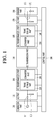
- Fig. 1 illustrated a High Voltage DC (HVDC) transmission system according to an embodiment.
- HVDC High Voltage DC
- an HVDC system 100 includes a generation part 101, a transmission side AC part 110, a transmission side DC transformation part 103, a DC transmission part 140, a demand side DC transformation part 105, a demand side AC part 170, a demand part 180, and a control part 190.
- the transmission side DC transformation part 103 includes a transmission side transformer part 120 and a transmission side converter part 130.
- the demand side DC transformation part 105 includes a demand side converter part 150 and a demand side transformer part 160.
- the generation part 101 generates 3-phase AC power.
- the generation part 101 may include a plurality of power plants.
- the transmission side AC part 110 delivers 3-phase AC power generated by the generation part 101 to the transmission side DC transformation part 103 including the transmission side transformer part 120 and the transmission side converter part 130.
- the transmission side DC transformation part 103 may include a DC substation.
- the transmission side transformer part 120 isolates the transmission side AC part 110 from the transmission side converter part 130 and the DC transmission part 140.
- the transmission side converter part 130 converts, into DC power, 3-phase AC power corresponding to an output of the transmission side transformer part 120.
- the DC transmission part 140 delivers the transmission side DC power to the demand side.
- the demand side converter part 150 converts the DC power delivered by the DC transmission part 140 into 3-phase AC power.
- the demand side transformer part 160 isolates the demand side AC part 170 from the demand side converter part 150 and the DC transmission part 140.
- the demand side AC part 170 provides, to the demand part 180, 3-phase AC power corresponding to an output of the demand side transformer part 160.
- the control part 190 controls at least one of the generation part 101, transmission side AC part 110, transmission side DC transformation part 103, DC transmission part 140, demand side DC transformation part 105, demand side AC part 170, demand part 180, control part 190, transmission side converter part 130, and demand side converter part 150.
- the control part 190 may control turn-on and turn-off timings of a plurality of valves in the transmission side converter part 130 and the demand side converter part 150.
- the valve may correspond to a thyristor or an insulated gate bipolar transistor (IGBT).
- Fig. 2 illustrated a high voltage DC transmission system in a monopolar type according to an embodiment.
- Fig. 2 illustrates a system for transmitting monopole DC power.
- the monopole is assumed to be, but is not limited to, a positive pole.
- the transmission side AC part 110 includes an AC transmission line 111 and an AC filter 113.
- the AC transmission line 111 delivers 3-phase AC power generated by the generation part 101 to the transmission side transformer part 120.
- the AC filter 113 removes frequency components other than a frequency component used by the DC transformation part 103 from the delivered 3-phase AC power.
- the transmission side transformer part 120 includes one or more transformers for the positive pole.
- the transmission side converter part 130 includes an AC-to-positive pole DC converter 131 for generating positive pole DC power, and the AC-to-positive pole DC converter 131 includes one or more 3-phase valve bridges 131a respectively corresponding to one or more transformers 121.
- the AC-to-positive pole DC converter 131 may generate the positive pole DC power having 6 pulses by using AC power.
- a primary coil and a secondary coil of the one transformer 121 may have a Y-Y type connection or a Y- ⁇ type connection.
- the AC-to-positive pole DC converter 131 may generate the positive pole DC power having 12 pulses by using AC power.
- a primary coil and a secondary coil of one of the two transformers 121 may have a Y-Y type connection and a primary coil and a secondary coil of the other transformer 121 may have a Y- ⁇ type connection.
- the AC-to-positive pole DC converter 131 may generate the positive pole DC power having 18 pulses by using AC power. As the number of pulses of the positive pole DC power becomes larger, a price of the filter may become lowered.
- the DC transmission part 140 includes a transmission side positive pole DC filter 141, a positive pole DC transmission line 143, and a demand side positive pole DC filter 145.
- the transmission side positive pole DC filter 141 includes an inductor L1 and a capacitor C1, and DC-filters the positive pole DC power output from the AC-to-positive pole DC converter 131.
- the positive pole DC transmission line 143 has one DC line for transmitting positive pole DC power and may use the ground as a feedback path of a current.
- One or more switches may be disposed on the DC line.
- the demand side positive pole DC filter 145 includes an inductor L2 and a capacitor C2, and direct-filters positive pole power delivered through the positive pole DC transmission line 143.
- the demand side converter part 150 includes a positive pole DC-to-AC converter 151 and the positive pole DC-to-AC converter 151 includes one or more 3-phase valve bridges 151a.
- the demand side transformer part 160 includes, for the positive pole, one or more transformers 161 respectively corresponding to the one or more 3-phase valve bridges 151a.
- the positive pole DC-to-AC converter 151 may generate AC power having 6 pulses by using positive pole DC power.
- a primary coil and a secondary coil of the one transformer 161 may have a Y-Y type connection or a Y- ⁇ type connection.
- the positive pole DC-to-AC converter 151 may generate AC power having 12 pulses by using the positive pole DC power.
- a primary coil and a secondary coil of one of the two transformers 161 may have a Y-Y type connection and a primary coil and a secondary coil of the other transformer 161 may have a Y- ⁇ type connection.
- the positive pole DC-to-AC converter 151 may generate AC power having 18 pulses by using the positive pole DC power. As the number of pulses of the AC power becomes larger, a price of the filter may become lowered.
- the demand side AC part 170 includes an AC filter 171 and an AC transmission line 173.
- the AC filter 171 removes remaining frequency components other than a frequency component (e.g. 60 Hz) used by the demand part 180 from the AC power generated by the demand side transformer part 160.
- a frequency component e.g. 60 Hz
- the AC transmission line 173 delivers the filtered AC power to the demand part 180.
- Fig. 3 illustrated a bipolar type HVDC transmission system according to an embodiment.
- Fig. 3 illustrates a system for transmitting DC power having two poles.
- the two poles are assumed to be, but not limited to, a positive pole and a negative pole.
- the transmission side AC part 110 includes an AC transmission line 111 and an AC filter 113.
- the AC transmission line 111 delivers 3-phase AC power generated by the generation part 101 to the transmission side transformer part 120.
- the AC filter 113 removes frequency components other than a frequency component used by the AC transformation part 103 from the delivered 3-phase AC power.
- the transmission side transformer part 120 includes one or more transformers 121 for the positive pole and one or more transformers 122 for the negative pole.
- the transmission side converter part 130 includes an AC-to-positive pole DC converter 131 for generating the positive pole DC power and an AC-to-negative pole DC converter 132 for generating negative DC power, the AC-to-positive pole DC converter 131 includes one or more 3-phase valve bridges 131a respectively corresponding to one or more transformers 121 for the positive pole, and the AC-to-negative pole DC converter 132 includes one or more 3-phase valve bridges 132a respectively corresponding to one or more transformers 122 for the negative pole.
- the AC-to-positive pole DC converter 131 may generate the positive pole DC power having 6 pulses by using AC power.
- a primary coil and a secondary coil of the one transformer 121 may have a Y-Y type connection or a Y- ⁇ type connection.
- the AC-to-positive pole DC converter 131 may generate the positive pole DC power having 12 pulses by using AC power.
- a primary coil and a secondary coil of one of the two transformers 121 may have a Y-Y type connection and a primary coil and a secondary coil of the other transformer 121 may have a Y- ⁇ type connection.
- the AC-to-positive pole DC converter 131 may generate the positive pole DC power having 18 pulses by using AC power. As the number of pulses of the positive pole DC power becomes larger, a price of the filter may become lowered.
- the AC-to-negative pole DC converter 132 may generate the negative pole DC power having 6 pulses.
- a primary coil and a secondary coil of the one transformer 122 may have a Y-Y type connection or a Y- ⁇ type connection.
- the AC-to-negative pole DC converter 132 may generate the negative pole DC power having 12 pulses.
- a primary coil and a secondary coil of one of the two transformers 122 may have a Y-Y type connection and a primary coil and a secondary coil of the other transformer 122 may have a Y- ⁇ type connection.
- the AC-to-negative pole DC converter 132 may generate the negative pole DC power having 18 pulses. As the number of pulses of the negative pole DC power becomes larger, a price of the filter may become lowered.
- the DC transmission part 140 includes a transmission side positive pole DC filter 141, a transmission side negative pole DC filter 142, a positive pole DC transmission line 143, a negative pole DC transmission line 144, a demand side positive pole DC filter 145, and a demand side negative pole DC filter 146.
- the transmission side positive pole DC filter 141 includes an inductor L1 and a capacitor C1, and DC-filters the positive pole power output from the AC-to-positive pole DC converter 131.
- the transmission side negative pole DC filter 142 includes an inductor L3 and a capacitor C3, and DC-filters the negative pole power output from the AC-to-negative pole DC converter 132.
- the positive pole DC transmission line 143 has one DC line for transmitting the positive pole DC power and may use the ground as a feedback path of a current.
- One or more switches may be disposed on the DC line.
- the negative pole DC transmission line 144 has one DC line for transmitting the negative pole DC power and may use the ground as a feedback path of a current.
- One or more switches may be disposed on the DC line.
- the demand side positive pole DC filter 145 includes an inductor L2 and a capacitor C2, and DC-filters the positive pole power delivered through the positive pole DC transmission line 143.
- the demand side negative pole DC filter 146 includes an inductor L4 and a capacitor C4, and DC-filters the negative pole power delivered through the negative pole DC transmission line 144.
- the demand side converter part 150 includes a positive pole DC-to-AC converter 151 and a negative pole DC-to-AC converter 152, and the positive pole DC-to-AC converter 151 includes one or more 3-phase valve bridges 151a, and the negative pole DC-to-AC converter 152 includes one or more 3-phase valve bridges 152a.
- the demand side transformer part 160 includes, for the positive pole, one or more transformers 161 respectively corresponding to one or more 3-phase valve bridges 151a, and one or more transformers 162, for the negative pole, respectively corresponding to one or more 3-phase valve bridges 152a.
- the positive pole DC-to-AC converter 151 may generate AC power having 6 pulses by using the positive pole DC power.
- a primary coil and a secondary coil of the one transformer 161 may have a Y-Y type connection or a Y- ⁇ type connection.
- the positive pole DC-to-AC converter 151 may generate AC power having 12 pulses by using the positive pole DC power.
- a primary coil and a secondary coil of one of the two transformers 161 may have a Y-Y type connection and a primary coil and a secondary coil of the other transformer 161 may have a Y- ⁇ type connection.
- the positive pole DC-to-AC converter 151 may generate AC power having 18 pulses by using the positive pole DC power. As the number of pulses of the AC power becomes larger, a price of the filter may become lowered.
- the negative pole DC-to-AC converter 152 may generate AC power having 6 pulses by using the negative pole DC power.
- a primary coil and a secondary coil of the one transformer 162 may have a Y-Y type connection or a Y- ⁇ type connection.
- the negative pole DC-to-AC converter 152 may generate AC power having 12 pulses by using the negative pole DC power.
- a primary coil and a secondary coil of one of the two transformers 162 may have a Y-Y type connection and a primary coil and a secondary coil of the other transformer 162 may have a Y- ⁇ type connection.
- the negative pole DC-to-AC converter 152 may generate AC power having 18 pulses by using the negative pole DC power. As the number of pulses of the AC power becomes larger, a price of the filter may become lowered.
- the demand side AC part 170 includes an AC filter 171 and an AC transmission line 173.
- the AC filter 171 removes remaining frequency components other than a frequency component (e.g. 60 Hz) used by the demand part 180 from the AC power generated by the demand side transformer part 160.
- a frequency component e.g. 60 Hz
- the AC transmission line 173 delivers the filtered AC power to the demand part 180.
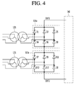
- Fig. 4 illustrates a connection between a transformer and a three-phase valve bridge according to an embodiment.
- Fig. 4 shows connections between two transformers 121 for positive pole and two 3-phase valve bridges 131a for positive pole.
- Connections between two transformers 122 for negative pole and two 3-phase valve bridges 132a for negative pole, connections between two transformers 161 of positive pole and two 3-phase valve bridges 151a for positive pole, connections between two transformers 162 of negative pole and two 3-phase valve bridges 152a for negative pole, a connection between one transformer 121 of positive pole and one 3-phase valve bridge 131a for positive pole, and a connection between one transformer 161 of positive pole and one 3-phase valve bridge 151a for positive pole may be easily derived from the embodiment of Fig. 4 , and accordingly drawings and descriptions thereof will be omitted.
- the transformer 121 having a Y-Y type connection is called as an upper transformer
- the transformer 121 having a Y- ⁇ type connection is called as a lower transformer
- the 3-phase valve bridge 131a connected to the upper transformer is called as an upper 3-phase valve bridge
- the 3-phase valve bridge 131a connected to the lower transformer is called as a lower 3-phase valve bridge.
- the upper 3-phase valve bridge and the lower 3-phase valve bridge have a first output terminal OUT1 and a second output terminal OUT2 which are two output terminals through which DC power is output.
- the upper 3-phase valve bridge includes 6 valves D1 to D6, and the lower 3-phase bridge includes 6 valves D7 to D12.
- the valve D1 includes a cathode connected to the first output terminal OUT1 and an anode connected to a first terminal of a secondary coil of the upper transformer.
- the valve D2 includes a cathode connected to an anode of the valve D5 and an anode connected to an anode of the valve D6.
- the valve D3 includes a cathode connected to the first output terminal OUT1 and an anode connected to a second terminal of the secondary coil of the upper transformer.
- the valve D4 includes a cathode connected to the anode of the valve D1 and an anode connected to an anode of the valve D6.
- the valve D5 includes a cathode connected to the first output terminal OUT1 and an anode connected to a third terminal of the secondary coil of the upper transformer.
- the valve D6 includes a cathode connected to the anode of the valve D3.
- the valve D7 includes a cathode connected to the anode of the valve D6 and an anode connected to the first terminal of the secondary coil of the lower transformer.
- the valve D8 includes a cathode connected to an anode of the valve D11 and an anode connected to the second output terminal OUT2.
- the valve D9 includes a cathode connected to the anode of the valve D6 and an anode connected to the second terminal of the secondary coil of the lower transformer.
- the valve D10 includes a cathode connected to the anode of the valve D7 and an anode connected to the second output terminal OUT2.
- the valve D11 includes a cathode connected to the anode of the valve D6 and the anode connected to the third terminal of the secondary coil of the lower transformer.
- the valve D12 includes a cathode connected to the anode of the valve D7 and an anode connected to the second output terminal OUT2.
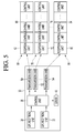
- Fig. 5 is a block diagram illustrating a data control system according to an embodiment.
- a data control system includes a transmission module 10 and a plurality of control modules 60, 70, and 80.
- the transmission module 10 wirelessly receives data from yards or fields through wireless communication, and transmits the received data to the plurality of control modules 60, 70, and 80.
- the data relates to power information which includes, for example, but is not limited to, a voltage value, a current value, whether an error occurs in a sensor installed in the yard or field, or state information for the yard or field.
- Each of the control modules 60, 70, and 80 properly controls and processes the data transmitted from the transmission module 10.
- the control modules 60, 70, and 80 may respectively include reception units 62, 72, and 82 and a plurality of control units 64, 74, and 84.
- a first control module 60 may include a reception unit 62 and a plurality of control unit 64.
- a data stream transmitted from the transmission module 10 and received by the reception unit 62 is provided to the plurality of control unit 64 and each of the plurality of control unit 64 may perform a control according to data included in the data stream.
- the plurality of control unit 64 may perform an identical control or different controls from each other.
- the transmission module 10 includes one or more GPS reception units 20 and 22, a control unit 30, a server 40, and a plurality of transmission units 50, 52, and 54.
- the GPS reception units 20 and 22 wirelessly receive data from yards or fields to transmit the received data to the control unit 30.
- the GPS reception units 20 and 22 and the control unit 30 may be connected to each other through an optical cable, but the embodiment is not limited thereto.
- Each of the reception units 20 and 22 is responsible for several yards or fields, and data collected from several yards or fields may be wirelessly transmitted to the GPS reception units 20 and 22. Accordingly, in order to cover lots of yards and fields, the GPS reception units 20 and 22 may be provided by at least one or more.
- the control unit 30 may process data transmitted from the GPS reception units 20 and 22.
- control unit 30 may generate data to be transmitted to the plurality of control modules 60, 70, and 80 based on the data transmitted from the GPS reception units 20 and 22.
- control unit 30 may include synchronization signal information ino the data to be transmitted to the plurality of control modules 60, 70, and 80.
- the synchronization signal information may include a corresponding data identification signal and time information.
- control unit 30 may receive a data stream from the GPS reception units 20 and 22 as illustrated in
- the data stream may include a control packet duration C and a data packet duration D.
- data transmitted from the yards or fields may be included in the data packet duration D of the data stream and transmitted to the control unit 30 through the GPS reception units 20 and 22.
- the control unit 30 may extract corresponding data Data n from the data stream transmitted through the GPS reception units 20 and 22 and generate a data stream including the synchronization signal information together with the extracted data.
- the data Data n extracted from the data stream is included in the data packet duration D1 and the synchronization signal information may be included in a dummy packet duration Dummy D1.
- another data may be included in the data packet period D2 of the data stream.
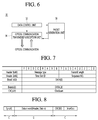
- the corresponding data Data n and the synchronization signal information may have a data packet structure illustrated in Fig. 7 .
- the data packet structure may include a message type field Message type, a transmission length information field Transmit length, a time information field Time slot ID, a data identification information field Sequence No., and a data field Data [0] to Data [28].
- time information field Time Slot ID and the data identification number field Sequence No. may configure the synchronization signal information.
- control unit 30 may transmit the data stream illustrated in FIG. 9 to each control module 60, 70, or 80 based on the data packet structure as illustrated in Fig. 7 .
- the data stream (see Fig. 9 ), which includes the synchronization signal information together with the extracted data, may be generated in correspondence to each control module 60, 70, or 80, which will receive the corresponding data stream, and may be transmitted to the corresponding control modules 60, 70, and 80 through the transmission units 50, 52, and 54 to which the generated data stream correspond.
- a data stream which includes the synchronization signal information together with the extracted data, is simultaneously transmitted to the plurality of transmission units 50, 52, and 54, and the transmission units 50, 52, and 54 may respectively transmit the corresponding data stream to the corresponding control modules 60, 70, and 80.
- the data stream including the synchronization signal information together with the extracted data is generated only once and simultaneously transmitted to the plurality of transmission units 50, 52, and 54.
- the plurality of transmission units 50, 52, and 54 may be transmit the data stream provided from the control unit 30 to the corresponding control modules 60, 70, and 80.
- the data stream provided from the control unit 30 may include data information and the synchronization signal information.
- the transmission units 50, 52, and 54 and the reception units 62, 72, and 82 of the control modules 60, 70, and 80 may be respectively connected through optical cables, but the embodiment is not limited thereto.
- the control modules 60, 70, and 80 may respectively include reception units 62, 72, and 82 for receiving the data stream transmitted from the corresponding transmission units 50, 52, and 54 in the transmission module 10 and a plurality of control units 64, 74, and 84 for performing controls proper to corresponding data based on the synchronization signal information included in the data stream received from the reception units 62, 72, and 82.
- each of the control units 64, 74, and 84 performs a control on corresponding data at an identical time based on the synchronization signal information included in the data stream, an error or malfunction, which is caused by asynchronization between the control modules 60, 70, and 80, may be prevented.
- a server 40 of the transmission module 10 communicates with the control unit 30, information in the control unit 30 may be transmitted to the server 40 and stored, or a command from the server 40 may be delivered to the control unit 30 and performed by the control unit 30.
- control unit 30 With reference to Fig. 6 , the control unit 30 according to the embodiment will be described in detail.
- Fig. 6 is a block diagram illustrating in detail the control unit of FIG. 5 .
- control unit 30 may include a data control unit 32, an optical communication transmission/reception unit 34, and a packet generation unit 36.
- the data control unit 32 is responsible for an overall control of the control unit 30.
- the data control unit 32 may control to extract data from the data stream transmitted from the GPS reception units 20 and 22 to the optical communication transmission/reception unit 34 and then delivered to the packet generation unit 36, and to generate, in addition to the extracted data, a new data stream to which the synchronization signal information is added.
- the data control unit 32 performs communication with the server 40 to transmit the corresponding synchronization signal information to the server 40, or receive the corresponding synchronization signal information from the server 40 under a control of the server 40 to include the received synchronization signal information in a corresponding data stream, but the embodiment is not limited thereto.
- the optical communication transmission/reception unit 34 may include a reception stage connected to the GPS reception units 20 and 22 through a first optical communication cable and a plurality of transmission stages connected to the plurality of transmission units 50, 52, and 54 through a second optical communication cable.
- the data stream which includes specific data transmitted from the GPS reception units 20 and 22, may be input to the reception stage of the optical communication transmission/reception unit 34 through the first optical communication cable.
- the data steam (hereinafter, a first data stream) input to the reception stage may be delivered to the packet generation unit 36.
- the packet generation unit 36 may extract corresponding specific data from the data stream under the control of the data control unit 32 and generate a new data stream (hereinafter a second data stream) in which the synchronization signal information provided from the data control unit 32 is added to the extracted data.
- the packet generation unit 36 may generate the second data stream, which includes the synchronization signal as illustrated in Fig. 9 , based on the first data stream as illustrated in Fig. 8 .
- the packet generation unit 36 may deliver the second data stream to the optical communication transmission/reception unit 34.
- the plurality of reception stages of the optical communication transmission/reception unit 34 may simultaneously deliver the second data stream, which has been delivered from the packet generation unit 36, to the plurality of corresponding transmission units 50, 52, and 54 through the second optical communication cable.
- the second data stream may be simultaneously transmitted to the reception units 62, 72, and 82 of the corresponding control modules 60, 70, and 80 through the plurality of transmission units 50, 52, and 54.
- Each of the control modules 60, 70, and 80 may extract the synchronization signal information included in the second data stream and simultaneously perform a control according to the corresponding data based on the synchronization signal information.
- each of the control modules 60, 70, and 80 since the synchronization signal information is transmitted together with the corresponding data before transmission to each of the control modules 60, 70, and 80, and each of the control modules 60, 70, and 80 may simultaneously perform a control according to the corresponding data at a synchronized time based on the synchronization signal information, an error or malfunction, which is caused by asynchronization between each control module 60, 70, and 80, may be prevented.
- the above-described method may be implemented as a processor-readable code on a medium with a program recorded thereon.
- the computer readable recording medium include a read-only memory (ROM), random-access memory (RAM), CD-ROMs, magnetic tapes, floppy disks, and optical data storage devices, and also include carrier waves (such as data transmission through the Internet).
Landscapes
- Engineering & Computer Science (AREA)
- Power Engineering (AREA)
- Computer Networks & Wireless Communication (AREA)
- Signal Processing (AREA)
- Physics & Mathematics (AREA)
- Electromagnetism (AREA)
- Optics & Photonics (AREA)
- Supply And Distribution Of Alternating Current (AREA)
- Direct Current Feeding And Distribution (AREA)
- Synchronisation In Digital Transmission Systems (AREA)
- General Physics & Mathematics (AREA)
- Rectifiers (AREA)
Abstract
Description
- The present disclosure relates to a data control system and particularly to a data control system capable of improving data reliability through synchronization.
- A High voltage DC (HVDC) transmission scheme is a power transmission scheme in which AC power of a high voltage generated in a power plant is converted into DC power and transmitted, and then the DC power is converted again into AC power in a power reception area. In a HVDC transmission system, data collected from a plurality of yards or fields is transmitted to a plurality of control modules in which controls are performed according to the received data.
- However, in a typical HVDC transmission system, there are cases where the collected data is transmitted to each control module at different times. Accordingly, since controls are performed according to the received data at different times in each control module, errors or malfunctions may occur.
- Synchronization is very important for a valve control in the HVDC transmission system, and when the valve control is performed in a state where synchronization is not performed, a considerable power loss may result.
- Embodiments provide a data control system capable of transmitting synchronization signal information at the time of data transmission to enable an error or malfunction due to asynchronization to be prevented.
- In one embodiment, a data control system includes: a transmission module configured to add synchronization signal information to data included in a first data stream to generate a second data stream; and a plurality of control modules configured to receive the second data stream from the transmission module, wherein the data includes power information.
- The details of one or more embodiments are set forth in the accompanying drawings and the description below. Other features will be apparent from the description and drawings, and from the claims.
-
-
Fig. 1 illustrates a High Voltage DC (HVDC) transmission system according to an embodiment. -
Fig. 2 illustrates a monopolar type HVDC transmission system according to an embodiment. -
Fig. 3 illustrates a bipolar type HVDC transmission system according to an embodiment. -
Fig. 4 illustrates a connection between a transformer and a 3-phase valve bridge according to an embodiment. -
Fig. 5 is a block diagram illustrating a data control system according to an embodiment. -
Fig. 6 is a block diagram illustrating in detail the control unit ofFig. 5 . -
Fig. 7 illustrates a data packet structure for data transmission. -
Fig. 8 illustrates a data stream structure received by the control unit ofFig. 5 . -
Fig. 9 illustrates a data stream structure transmitted from the control unit ofFig. 5 . - Reference will now be made in detail to the embodiments of the present disclosure, examples of which are illustrated in the accompanying drawings. In the following description, usage of suffixes such as 'module', 'part' or 'unit' used for referring to elements is given merely to facilitate explanation of the present invention, without having any significant meaning by itself.
-
Fig. 1 illustrated a High Voltage DC (HVDC) transmission system according to an embodiment. - As illustrated in
Fig. 1 , an HVDC system 100 according to an embodiment includes ageneration part 101, a transmissionside AC part 110, a transmission sideDC transformation part 103, aDC transmission part 140, a demand sideDC transformation part 105, a demandside AC part 170, ademand part 180, and acontrol part 190. The transmission sideDC transformation part 103 includes a transmissionside transformer part 120 and a transmissionside converter part 130. The demand sideDC transformation part 105 includes a demandside converter part 150 and a demandside transformer part 160. - The
generation part 101 generates 3-phase AC power. Thegeneration part 101 may include a plurality of power plants. - The transmission
side AC part 110 delivers 3-phase AC power generated by thegeneration part 101 to the transmission sideDC transformation part 103 including the transmissionside transformer part 120 and the transmissionside converter part 130. The transmission sideDC transformation part 103 may include a DC substation. - The transmission
side transformer part 120 isolates the transmissionside AC part 110 from the transmissionside converter part 130 and theDC transmission part 140. - The transmission
side converter part 130 converts, into DC power, 3-phase AC power corresponding to an output of the transmissionside transformer part 120. - The
DC transmission part 140 delivers the transmission side DC power to the demand side. - The demand
side converter part 150 converts the DC power delivered by theDC transmission part 140 into 3-phase AC power. - The demand
side transformer part 160 isolates the demandside AC part 170 from the demandside converter part 150 and theDC transmission part 140. - The demand
side AC part 170 provides, to thedemand part 180, 3-phase AC power corresponding to an output of the demandside transformer part 160. - The
control part 190 controls at least one of thegeneration part 101, transmissionside AC part 110, transmission sideDC transformation part 103,DC transmission part 140, demand sideDC transformation part 105, demandside AC part 170,demand part 180,control part 190, transmissionside converter part 130, and demandside converter part 150. In particular, thecontrol part 190 may control turn-on and turn-off timings of a plurality of valves in the transmissionside converter part 130 and the demandside converter part 150. At this point, the valve may correspond to a thyristor or an insulated gate bipolar transistor (IGBT). -
Fig. 2 illustrated a high voltage DC transmission system in a monopolar type according to an embodiment. - In particular,
Fig. 2 illustrates a system for transmitting monopole DC power. Hereinafter the monopole is assumed to be, but is not limited to, a positive pole. - The transmission
side AC part 110 includes anAC transmission line 111 and anAC filter 113. - The
AC transmission line 111 delivers 3-phase AC power generated by thegeneration part 101 to the transmissionside transformer part 120. - The
AC filter 113 removes frequency components other than a frequency component used by theDC transformation part 103 from the delivered 3-phase AC power. - The transmission
side transformer part 120 includes one or more transformers for the positive pole. For the positive pole, the transmissionside converter part 130 includes an AC-to-positivepole DC converter 131 for generating positive pole DC power, and the AC-to-positivepole DC converter 131 includes one or more 3-phase valve bridges 131a respectively corresponding to one ormore transformers 121. - When one 3-
phase valve bridge 131a is used, the AC-to-positivepole DC converter 131 may generate the positive pole DC power having 6 pulses by using AC power. At this point, a primary coil and a secondary coil of the onetransformer 121 may have a Y-Y type connection or a Y-Δ type connection. - When two 3-
phase valve bridges 131a are used, the AC-to-positivepole DC converter 131 may generate the positive pole DC power having 12 pulses by using AC power. At this point, a primary coil and a secondary coil of one of the twotransformers 121 may have a Y-Y type connection and a primary coil and a secondary coil of theother transformer 121 may have a Y-Δ type connection. - When three 3-
phase valve bridges 131a are used, the AC-to-positivepole DC converter 131 may generate the positive pole DC power having 18 pulses by using AC power. As the number of pulses of the positive pole DC power becomes larger, a price of the filter may become lowered. - The
DC transmission part 140 includes a transmission side positivepole DC filter 141, a positive poleDC transmission line 143, and a demand side positivepole DC filter 145. - The transmission side positive
pole DC filter 141 includes an inductor L1 and a capacitor C1, and DC-filters the positive pole DC power output from the AC-to-positivepole DC converter 131. - The positive pole
DC transmission line 143 has one DC line for transmitting positive pole DC power and may use the ground as a feedback path of a current. One or more switches may be disposed on the DC line. - The demand side positive
pole DC filter 145 includes an inductor L2 and a capacitor C2, and direct-filters positive pole power delivered through the positive poleDC transmission line 143. - The demand
side converter part 150 includes a positive pole DC-to-AC converter 151 and the positive pole DC-to-AC converter 151 includes one or more 3-phase valve bridges 151a. - The demand
side transformer part 160 includes, for the positive pole, one ormore transformers 161 respectively corresponding to the one or more 3-phase valve bridges 151a. - When one 3-
phase valve bridge 151a is used, the positive pole DC-to-AC converter 151 may generate AC power having 6 pulses by using positive pole DC power. At this point, a primary coil and a secondary coil of the onetransformer 161 may have a Y-Y type connection or a Y-Δ type connection. - When two 3-
phase valve bridges 151a are used, the positive pole DC-to-AC converter 151 may generate AC power having 12 pulses by using the positive pole DC power. At this point, a primary coil and a secondary coil of one of the twotransformers 161 may have a Y-Y type connection and a primary coil and a secondary coil of theother transformer 161 may have a Y-Δ type connection. - When three 3-
phase valve bridges 151a are used, the positive pole DC-to-AC converter 151 may generate AC power having 18 pulses by using the positive pole DC power. As the number of pulses of the AC power becomes larger, a price of the filter may become lowered. - The demand
side AC part 170 includes anAC filter 171 and anAC transmission line 173. - The
AC filter 171 removes remaining frequency components other than a frequency component (e.g. 60 Hz) used by thedemand part 180 from the AC power generated by the demandside transformer part 160. - The
AC transmission line 173 delivers the filtered AC power to thedemand part 180. -
Fig. 3 illustrated a bipolar type HVDC transmission system according to an embodiment. - In particular,
Fig. 3 illustrates a system for transmitting DC power having two poles. Hereinafter the two poles are assumed to be, but not limited to, a positive pole and a negative pole. - The transmission
side AC part 110 includes anAC transmission line 111 and anAC filter 113. - The
AC transmission line 111 delivers 3-phase AC power generated by thegeneration part 101 to the transmissionside transformer part 120. - The
AC filter 113 removes frequency components other than a frequency component used by theAC transformation part 103 from the delivered 3-phase AC power. - The transmission
side transformer part 120 includes one ormore transformers 121 for the positive pole and one ormore transformers 122 for the negative pole. The transmissionside converter part 130 includes an AC-to-positivepole DC converter 131 for generating the positive pole DC power and an AC-to-negative pole DC converter 132 for generating negative DC power, the AC-to-positivepole DC converter 131 includes one or more 3-phase valve bridges 131a respectively corresponding to one ormore transformers 121 for the positive pole, and the AC-to-negative pole DC converter 132 includes one or more 3-phase valve bridges 132a respectively corresponding to one ormore transformers 122 for the negative pole. - When one 3-
phase valve bridge 131a is used for the positive pole, the AC-to-positivepole DC converter 131 may generate the positive pole DC power having 6 pulses by using AC power. At this point, a primary coil and a secondary coil of the onetransformer 121 may have a Y-Y type connection or a Y-Δ type connection. - When two 3-
phase valve bridges 131a are used for the positive pole, the AC-to-positivepole DC converter 131 may generate the positive pole DC power having 12 pulses by using AC power. At this point, a primary coil and a secondary coil of one of the twotransformers 121 may have a Y-Y type connection and a primary coil and a secondary coil of theother transformer 121 may have a Y-Δ type connection. - When three 3-
phase valve bridges 131a are used for the positive pole, the AC-to-positivepole DC converter 131 may generate the positive pole DC power having 18 pulses by using AC power. As the number of pulses of the positive pole DC power becomes larger, a price of the filter may become lowered. - When one 3-
phase valve bridge 132a is used for the negative pole, the AC-to-negative pole DC converter 132 may generate the negative pole DC power having 6 pulses. At this point, a primary coil and a secondary coil of the onetransformer 122 may have a Y-Y type connection or a Y-Δ type connection. - When two 3-
phase valve bridges 132a are used for the negative pole, the AC-to-negative pole DC converter 132 may generate the negative pole DC power having 12 pulses. At this point, a primary coil and a secondary coil of one of the twotransformers 122 may have a Y-Y type connection and a primary coil and a secondary coil of theother transformer 122 may have a Y-Δ type connection. - When three 3-
phase valve bridges 132a are used for the negative pole, the AC-to-negative pole DC converter 132 may generate the negative pole DC power having 18 pulses. As the number of pulses of the negative pole DC power becomes larger, a price of the filter may become lowered. - The
DC transmission part 140 includes a transmission side positivepole DC filter 141, a transmission side negativepole DC filter 142, a positive poleDC transmission line 143, a negative poleDC transmission line 144, a demand side positivepole DC filter 145, and a demand side negativepole DC filter 146. - The transmission side positive
pole DC filter 141 includes an inductor L1 and a capacitor C1, and DC-filters the positive pole power output from the AC-to-positivepole DC converter 131. - The transmission side negative
pole DC filter 142 includes an inductor L3 and a capacitor C3, and DC-filters the negative pole power output from the AC-to-negative pole DC converter 132. - The positive pole
DC transmission line 143 has one DC line for transmitting the positive pole DC power and may use the ground as a feedback path of a current. One or more switches may be disposed on the DC line. - The negative pole
DC transmission line 144 has one DC line for transmitting the negative pole DC power and may use the ground as a feedback path of a current. One or more switches may be disposed on the DC line. - The demand side positive
pole DC filter 145 includes an inductor L2 and a capacitor C2, and DC-filters the positive pole power delivered through the positive poleDC transmission line 143. - The demand side negative
pole DC filter 146 includes an inductor L4 and a capacitor C4, and DC-filters the negative pole power delivered through the negative poleDC transmission line 144. - The demand
side converter part 150 includes a positive pole DC-to-AC converter 151 and a negative pole DC-to-AC converter 152, and the positive pole DC-to-AC converter 151 includes one or more 3-phase valve bridges 151a, and the negative pole DC-to-AC converter 152 includes one or more 3-phase valve bridges 152a. - The demand
side transformer part 160 includes, for the positive pole, one ormore transformers 161 respectively corresponding to one or more 3-phase valve bridges 151a, and one ormore transformers 162, for the negative pole, respectively corresponding to one or more 3-phase valve bridges 152a. - When one 3-
phase valve bridge 151a is used for the positive pole, the positive pole DC-to-AC converter 151 may generate AC power having 6 pulses by using the positive pole DC power. At this point, a primary coil and a secondary coil of the onetransformer 161 may have a Y-Y type connection or a Y-Δ type connection. - When two 3-
phase valve bridges 151a are used for the positive pole, the positive pole DC-to-AC converter 151 may generate AC power having 12 pulses by using the positive pole DC power. At this point, a primary coil and a secondary coil of one of the twotransformers 161 may have a Y-Y type connection and a primary coil and a secondary coil of theother transformer 161 may have a Y-Δ type connection. - When three 3-
phase valve bridges 151a are used for the positive pole, the positive pole DC-to-AC converter 151 may generate AC power having 18 pulses by using the positive pole DC power. As the number of pulses of the AC power becomes larger, a price of the filter may become lowered. - When one 3-
phase valve bridge 152a is used for the negative pole, the negative pole DC-to-AC converter 152 may generate AC power having 6 pulses by using the negative pole DC power. At this point, a primary coil and a secondary coil of the onetransformer 162 may have a Y-Y type connection or a Y-Δ type connection. - When two 3-
phase valve bridges 152a are used for the negative pole, the negative pole DC-to-AC converter 152 may generate AC power having 12 pulses by using the negative pole DC power. At this point, a primary coil and a secondary coil of one of the twotransformers 162 may have a Y-Y type connection and a primary coil and a secondary coil of theother transformer 162 may have a Y-Δ type connection. - When three 3-
phase valve bridges 152a are used for the negative pole, the negative pole DC-to-AC converter 152 may generate AC power having 18 pulses by using the negative pole DC power. As the number of pulses of the AC power becomes larger, a price of the filter may become lowered. - The demand
side AC part 170 includes anAC filter 171 and anAC transmission line 173. - The
AC filter 171 removes remaining frequency components other than a frequency component (e.g. 60 Hz) used by thedemand part 180 from the AC power generated by the demandside transformer part 160. - The
AC transmission line 173 delivers the filtered AC power to thedemand part 180. -
Fig. 4 illustrates a connection between a transformer and a three-phase valve bridge according to an embodiment. - In particular,
Fig. 4 shows connections between twotransformers 121 for positive pole and two 3-phase valve bridges 131a for positive pole. Connections between twotransformers 122 for negative pole and two 3-phase valve bridges 132a for negative pole, connections between twotransformers 161 of positive pole and two 3-phase valve bridges 151a for positive pole, connections between twotransformers 162 of negative pole and two 3-phase valve bridges 152a for negative pole, a connection between onetransformer 121 of positive pole and one 3-phase valve bridge 131a for positive pole, and a connection between onetransformer 161 of positive pole and one 3-phase valve bridge 151a for positive pole may be easily derived from the embodiment ofFig. 4 , and accordingly drawings and descriptions thereof will be omitted. - In
Fig. 4 , thetransformer 121 having a Y-Y type connection is called as an upper transformer, thetransformer 121 having a Y-Δ type connection is called as a lower transformer, the 3-phase valve bridge 131a connected to the upper transformer is called as an upper 3-phase valve bridge, and the 3-phase valve bridge 131a connected to the lower transformer is called as a lower 3-phase valve bridge. - The upper 3-phase valve bridge and the lower 3-phase valve bridge have a first output terminal OUT1 and a second output terminal OUT2 which are two output terminals through which DC power is output.
- The upper 3-phase valve bridge includes 6 valves D1 to D6, and the lower 3-phase bridge includes 6 valves D7 to D12.
- The valve D1 includes a cathode connected to the first output terminal OUT1 and an anode connected to a first terminal of a secondary coil of the upper transformer.
- The valve D2 includes a cathode connected to an anode of the valve D5 and an anode connected to an anode of the valve D6.
- The valve D3 includes a cathode connected to the first output terminal OUT1 and an anode connected to a second terminal of the secondary coil of the upper transformer.
- The valve D4 includes a cathode connected to the anode of the valve D1 and an anode connected to an anode of the valve D6.
- The valve D5 includes a cathode connected to the first output terminal OUT1 and an anode connected to a third terminal of the secondary coil of the upper transformer.
- The valve D6 includes a cathode connected to the anode of the valve D3.
- The valve D7 includes a cathode connected to the anode of the valve D6 and an anode connected to the first terminal of the secondary coil of the lower transformer.
- The valve D8 includes a cathode connected to an anode of the valve D11 and an anode connected to the second output terminal OUT2.
- The valve D9 includes a cathode connected to the anode of the valve D6 and an anode connected to the second terminal of the secondary coil of the lower transformer.
- The valve D10 includes a cathode connected to the anode of the valve D7 and an anode connected to the second output terminal OUT2.
- The valve D11 includes a cathode connected to the anode of the valve D6 and the anode connected to the third terminal of the secondary coil of the lower transformer.
- The valve D12 includes a cathode connected to the anode of the valve D7 and an anode connected to the second output terminal OUT2.
-
Fig. 5 is a block diagram illustrating a data control system according to an embodiment. - Referring to
Fig. 5 , a data control system according to an embodiment includes atransmission module 10 and a plurality ofcontrol modules - The
transmission module 10 wirelessly receives data from yards or fields through wireless communication, and transmits the received data to the plurality ofcontrol modules - The data relates to power information which includes, for example, but is not limited to, a voltage value, a current value, whether an error occurs in a sensor installed in the yard or field, or state information for the yard or field.
- Each of the
control modules transmission module 10. - The
control modules reception units control units first control module 60 may include areception unit 62 and a plurality ofcontrol unit 64. A data stream transmitted from thetransmission module 10 and received by thereception unit 62 is provided to the plurality ofcontrol unit 64 and each of the plurality ofcontrol unit 64 may perform a control according to data included in the data stream. The plurality ofcontrol unit 64 may perform an identical control or different controls from each other. - The
transmission module 10 includes one or moreGPS reception units control unit 30, aserver 40, and a plurality oftransmission units - The
GPS reception units control unit 30. - The
GPS reception units control unit 30 may be connected to each other through an optical cable, but the embodiment is not limited thereto. - Each of the
reception units GPS reception units GPS reception units - The
control unit 30 may process data transmitted from theGPS reception units - In detail, the
control unit 30 may generate data to be transmitted to the plurality ofcontrol modules GPS reception units control unit 30 may include synchronization signal information ino the data to be transmitted to the plurality ofcontrol modules - For example, the
control unit 30 may receive a data stream from theGPS reception units -
Fig. 8 . - As illustrated in
Fig. 8 , the data stream may include a control packet duration C and a data packet duration D. - Accordingly, data transmitted from the yards or fields may be included in the data packet duration D of the data stream and transmitted to the
control unit 30 through theGPS reception units - The
control unit 30 may extract corresponding data Data n from the data stream transmitted through theGPS reception units Fig. 9 , the data Data n extracted from the data stream is included in the data packet duration D1 and the synchronization signal information may be included in a dummy packet duration Dummy D1. - As illustrated in
Fig. 9 , another data may be included in the data packet period D2 of the data stream. - The corresponding data Data n and the synchronization signal information may have a data packet structure illustrated in
Fig. 7 . - In other words, the data packet structure may include a message type field Message type, a transmission length information field Transmit length, a time information field Time slot ID, a data identification information field Sequence No., and a data field Data [0] to Data [28].
- Here, the time information field Time Slot ID and the data identification number field Sequence No. may configure the synchronization signal information.
- In the end, the
control unit 30 may transmit the data stream illustrated inFIG. 9 to eachcontrol module Fig. 7 . - The data stream (see
Fig. 9 ), which includes the synchronization signal information together with the extracted data, may be generated in correspondence to eachcontrol module corresponding control modules transmission units - As another example, a data stream, which includes the synchronization signal information together with the extracted data, is simultaneously transmitted to the plurality of
transmission units transmission units corresponding control modules transmission units - The plurality of
transmission units control unit 30 to thecorresponding control modules control unit 30 may include data information and the synchronization signal information. - The
transmission units reception units control modules - The
control modules reception units transmission units transmission module 10 and a plurality ofcontrol units reception units - Since each of the
control units control modules - On the other hand, a
server 40 of thetransmission module 10 communicates with thecontrol unit 30, information in thecontrol unit 30 may be transmitted to theserver 40 and stored, or a command from theserver 40 may be delivered to thecontrol unit 30 and performed by thecontrol unit 30. - With reference to
Fig. 6 , thecontrol unit 30 according to the embodiment will be described in detail. -
Fig. 6 is a block diagram illustrating in detail the control unit ofFIG. 5 . - Referring to
Fig. 6 , thecontrol unit 30 may include adata control unit 32, an optical communication transmission/reception unit 34, and apacket generation unit 36. - The data control
unit 32 is responsible for an overall control of thecontrol unit 30. In particular, thedata control unit 32 may control to extract data from the data stream transmitted from theGPS reception units reception unit 34 and then delivered to thepacket generation unit 36, and to generate, in addition to the extracted data, a new data stream to which the synchronization signal information is added. - The data control
unit 32 performs communication with theserver 40 to transmit the corresponding synchronization signal information to theserver 40, or receive the corresponding synchronization signal information from theserver 40 under a control of theserver 40 to include the received synchronization signal information in a corresponding data stream, but the embodiment is not limited thereto. - The optical communication transmission/
reception unit 34 may include a reception stage connected to theGPS reception units transmission units - The data stream, which includes specific data transmitted from the
GPS reception units reception unit 34 through the first optical communication cable. The data steam (hereinafter, a first data stream) input to the reception stage may be delivered to thepacket generation unit 36. - The
packet generation unit 36 may extract corresponding specific data from the data stream under the control of thedata control unit 32 and generate a new data stream (hereinafter a second data stream) in which the synchronization signal information provided from thedata control unit 32 is added to the extracted data. - The
packet generation unit 36 may generate the second data stream, which includes the synchronization signal as illustrated inFig. 9 , based on the first data stream as illustrated inFig. 8 . - The
packet generation unit 36 may deliver the second data stream to the optical communication transmission/reception unit 34. - The plurality of reception stages of the optical communication transmission/
reception unit 34 may simultaneously deliver the second data stream, which has been delivered from thepacket generation unit 36, to the plurality ofcorresponding transmission units - In addition, the second data stream may be simultaneously transmitted to the
reception units corresponding control modules transmission units control modules - According to embodiments, since the synchronization signal information is transmitted together with the corresponding data before transmission to each of the
control modules control modules control module - In addition, according to embodiments, since controls according to corresponding data are simultaneously performed based on the synchronization signal information, a data loss due to asynchronization may be prevented to improve reliability.
- According to an embodiment, the above-described method may be implemented as a processor-readable code on a medium with a program recorded thereon. Examples of the computer readable recording medium include a read-only memory (ROM), random-access memory (RAM), CD-ROMs, magnetic tapes, floppy disks, and optical data storage devices, and also include carrier waves (such as data transmission through the Internet).
- As can be seen from the foregoing, the above-described embodiments is not limited to the configurations and methods of the embodiments described above, but the entirety of or a part of the embodiments may be configured to be selectively combined such that various modifications of the embodiments can be implemented.
- Although embodiments have been described with reference to a number of illustrative embodiments thereof, it should be understood that numerous other modifications and embodiments can be devised by those skilled in the art that will fall within the scope of the principles of this disclosure. More particularly, various variations and modifications are possible in the component parts and/or arrangements of the subject combination arrangement within the scope of the disclosure, the drawings and the appended claims. In addition to variations and modifications in the component parts and/or arrangements, alternative uses will also be apparent to those skilled in the art.
Claims (14)
- A data control system, comprising:a transmission module (10) configured to add synchronization signal information to data included in a first data stream to generate a second data stream; anda plurality of control modules (60, 70, 80) configured to receive the second data stream from the transmission module (10),wherein the data comprises power information.
- The data control system according to claim 1, wherein the transmission module (10) comprises:at least one GPS reception unit (20, 22) configured to receive the first data stream;a control unit (30) connected to the at least one GPS reception unit (20, 22) and configured to extract the data from the received first data stream and generate the second data stream comprising the extracted data and the synchronization signal information; anda plurality of transmission units (50, 52, 54) connected to the control unit (30) and configured to transmit the second data stream to the plurality of control modules (60, 70, 80).
- The data control system according to claim 2, wherein the first data stream is collected from a yard or a field to be transmitted.
- The data control system according to claim 2, wherein the second data stream is separately generated and transmitted to the plurality of control modules (60, 70, 80).
- The data control system according to claim 2, wherein the second data stream is generated once and simultaneously transmitted to the plurality of control modules (60, 70, 80).
- The data control system according to claim 2, wherein the transmission module (10) further comprises a server (40) configured to receive the synchronization signal information or transmit the synchronization signal information to the control unit (30).
- The data control system according to claim 2, wherein the control unit (30) comprises:a packet generation unit (36) configured to generate the second data stream based on the first data stream; andan optical communication transmission/reception unit (34) comprising a reception stage configured to receive the first data stream and a plurality of transmission stages configured to transmit the second data stream generated from the packet generation unit (36) to the plurality of transmission units (50, 52, 54).
- The data control system according to claim 7, wherein the reception unit is connected to the GPS reception unit (20, 22) through a first optical communication cable, and
the transmission stages are connected to the plurality of transmission units (50, 52, 54) through corresponding second optical communication cables. - The data control system according to claim 1, wherein each of the plurality of control modules (60, 70, 80) comprises a reception unit (62, 72, 82), and
the plurality of transmission units (50, 52, 54) of the transmission module (10) and the plurality of reception units (62, 72, 82) are connected through optical communication cables so as to correspond to each other. - The data control system according to claim 9, wherein each of the plurality of control modules (60, 70, 80) further comprises a plurality of control units (64, 74, 84) configured to perform controls on the data at an identical time based on the synchronization signal information.
- The data control system according to claim 1, wherein the synchronization signal information is included in a dummy data duration of the second data stream.
- The data control system according to claim 11, wherein the dummy data duration comprises time information as the synchronization signal information and data identification information.
- The data control system according to claim 1, wherein the first data stream is wirelessly received.
- The data control system according to claim 1, wherein the power information comprises at least one of a voltage value or a current value, whether an error occurs in a sensor installed in a yard or field, and state information for the yard or field.
Applications Claiming Priority (1)
| Application Number | Priority Date | Filing Date | Title |
|---|---|---|---|
| KR1020150106903A KR101667886B1 (en) | 2015-07-28 | 2015-07-28 | Data control system |
Publications (1)
| Publication Number | Publication Date |
|---|---|
| EP3125452A1 true EP3125452A1 (en) | 2017-02-01 |
Family
ID=55967035
Family Applications (1)
| Application Number | Title | Priority Date | Filing Date |
|---|---|---|---|
| EP16166745.6A Withdrawn EP3125452A1 (en) | 2015-07-28 | 2016-04-22 | Data control system |
Country Status (5)
| Country | Link |
|---|---|
| US (1) | US9948105B2 (en) |
| EP (1) | EP3125452A1 (en) |
| JP (1) | JP6445493B2 (en) |
| KR (1) | KR101667886B1 (en) |
| CN (1) | CN106411147B (en) |
Families Citing this family (2)
| Publication number | Priority date | Publication date | Assignee | Title |
|---|---|---|---|---|
| KR102064791B1 (en) * | 2015-04-23 | 2020-03-02 | 한국전자통신연구원 | Method and apparatus for minimizing data loss with protection switching in optical transport network system |
| CN111884229B (en) * | 2020-08-19 | 2022-03-08 | 南方电网科学研究院有限责任公司 | Asynchronous and synchronous control method and system for back-to-back flexible direct current power transmission system |
Citations (2)
| Publication number | Priority date | Publication date | Assignee | Title |
|---|---|---|---|---|
| WO2001017092A1 (en) * | 1999-08-27 | 2001-03-08 | Abb Ab | Electric power supervision |
| US20100150175A1 (en) * | 2007-05-14 | 2010-06-17 | Abb Technology Ag | Point-to-point communication in a high voltage power transmission system |
Family Cites Families (19)
| Publication number | Priority date | Publication date | Assignee | Title |
|---|---|---|---|---|
| KR100229991B1 (en) | 1996-11-29 | 1999-11-15 | 전주범 | Time stamper in transport stream |
| JP3718577B2 (en) * | 1997-03-28 | 2005-11-24 | ソニー株式会社 | Radio receiver and radio reception method |
| DE19757195A1 (en) | 1997-12-22 | 1999-06-24 | Philips Patentverwaltung | Method for transmitting an asynchronous data stream over a synchronous data bus, and circuit arrangement for carrying out the method |
| JP3352411B2 (en) * | 1998-03-05 | 2002-12-03 | 株式会社東芝 | Control system, power system protection control system, and storage medium storing program |
| US6275554B1 (en) | 1999-07-09 | 2001-08-14 | Thomson Licensing S.A. | Digital symbol timing recovery network |
| KR20030031711A (en) | 2001-10-15 | 2003-04-23 | (주)웨이브다임 | Position determining apparatus for mobile phone and the method |
| JP3960089B2 (en) * | 2002-03-15 | 2007-08-15 | 松下電器産業株式会社 | Control device, controlled device, local control device and control system |
| KR100580176B1 (en) | 2003-09-17 | 2006-05-15 | 삼성전자주식회사 | Display Synchronization Signal Generator in Digital Broadcasting Receiving System |
| CN101023488A (en) | 2004-09-17 | 2007-08-22 | 皇家飞利浦电子股份有限公司 | Method of converting a user bit-stream into a coded bit-stream, method of detecting synchronization patterns in a signal, record carrier, signal, recording apparatus and playback apparatus all using freely insertable synchronization patterns |
| US7920602B2 (en) | 2005-05-23 | 2011-04-05 | Samsung Electronics Co., Ltd. | Method for formatting digital broadcast transport stream packet for improved receiving performance, digital broadcast transmitter, and signal processing method thereof |
| CN1881744B (en) * | 2005-06-16 | 2010-05-12 | 许继集团有限公司 | Realization method of a real-time monitoring system for HVDC converter station |
| EP1830447A1 (en) | 2006-03-02 | 2007-09-05 | ABB Research Ltd | Converter control unit using time-stamped voltage or current phasors |
| JP5151211B2 (en) | 2007-03-30 | 2013-02-27 | ソニー株式会社 | Multi-screen synchronized playback system, display control terminal, multi-screen synchronized playback method, and program |
| US8582642B2 (en) | 2007-12-14 | 2013-11-12 | Samsung Electronics Co., Ltd. | Transmitting system and receiving system for processing stream, and stream processing methods thereof |
| KR101537760B1 (en) | 2007-12-14 | 2015-07-20 | 삼성전자주식회사 | Transmitting and receiving system for processing stream, and stream processing methods thereof |
| KR101172792B1 (en) * | 2008-11-26 | 2012-08-20 | 한국방송공사 | Added information insertion apparatus and method in broadcasting system |
| JP5320629B2 (en) * | 2009-08-26 | 2013-10-23 | 京セラ株式会社 | Wireless communication system, control method, and control apparatus |
| US20120156987A1 (en) * | 2009-08-26 | 2012-06-21 | Kyocera Corporation | Wireless communication system, wireless base station, control method, and control device |
| US8942856B2 (en) * | 2011-12-22 | 2015-01-27 | General Electric Company | Power converter and methods of controlling the same |
-
2015
- 2015-07-28 KR KR1020150106903A patent/KR101667886B1/en not_active Expired - Fee Related
-
2016
- 2016-04-22 EP EP16166745.6A patent/EP3125452A1/en not_active Withdrawn
- 2016-05-17 CN CN201610326423.1A patent/CN106411147B/en not_active Expired - Fee Related
- 2016-07-13 JP JP2016138275A patent/JP6445493B2/en not_active Expired - Fee Related
- 2016-07-27 US US15/221,480 patent/US9948105B2/en not_active Expired - Fee Related
Patent Citations (2)
| Publication number | Priority date | Publication date | Assignee | Title |
|---|---|---|---|---|
| WO2001017092A1 (en) * | 1999-08-27 | 2001-03-08 | Abb Ab | Electric power supervision |
| US20100150175A1 (en) * | 2007-05-14 | 2010-06-17 | Abb Technology Ag | Point-to-point communication in a high voltage power transmission system |
Non-Patent Citations (1)
| Title |
|---|
| SERIZAWA Y ET AL: "Wide-Area Current Differential Backup Protection Employing Broadband Communications and Time Transfer Systems", IEEE TRANSACTIONS ON POWER DELIVERY, IEEE SERVICE CENTER, NEW YORK, NY, US, vol. 13, no. 4, 1 October 1998 (1998-10-01), pages 1046 - 1052, XP011049626, ISSN: 0885-8977, DOI: 10.1109/61.714445 * |
Also Published As
| Publication number | Publication date |
|---|---|
| US9948105B2 (en) | 2018-04-17 |
| KR101667886B1 (en) | 2016-10-28 |
| CN106411147B (en) | 2019-04-30 |
| JP2017034665A (en) | 2017-02-09 |
| US20170033563A1 (en) | 2017-02-02 |
| JP6445493B2 (en) | 2018-12-26 |
| CN106411147A (en) | 2017-02-15 |
Similar Documents
| Publication | Publication Date | Title |
|---|---|---|
| JP6144717B2 (en) | Insulation design apparatus and method for high-voltage DC power transmission system | |
| KR101604906B1 (en) | High voltage direct current transmission system | |
| JP6162744B2 (en) | Modular multi-level converter | |
| US8541898B2 (en) | Control method and system for a wind power installation in case of grid faults | |
| US9948105B2 (en) | Data control system | |
| EP2945248B1 (en) | Apparatus and method for design of high voltage direct current transmission system | |
| US20160149509A1 (en) | Connecting power plants to high voltage networks | |
| JP6144718B2 (en) | Insulation design apparatus and method for high-voltage DC power transmission system | |
| EP3002847A1 (en) | High voltage direct current transmission system | |
| KR101717349B1 (en) | An apparatus and method for contingency analysis of hvdc system | |
| KR101596136B1 (en) | Data processing device for high voltage direct current transmission system and method thereof | |
| KR20160053873A (en) | Modular multi-level converter and controlling method thereof | |
| KR101622458B1 (en) | Hvdc converter and controlling method thereof | |
| KR101596134B1 (en) | Data processing device for high voltage direct current transmission system and method thereof | |
| KR101596135B1 (en) | Data processing device for high voltage direct current transmission system and method thereof | |
| KR101707768B1 (en) | Hvdc converter and controlling method thereof | |
| KR101707735B1 (en) | Hvdc converter and controlling method thereof | |
| KR20150124328A (en) | Hvdc converter and controlling method thereof | |
| KR20150130161A (en) | High voltage direct current transmission system and controlling method thereof |
Legal Events
| Date | Code | Title | Description |
|---|---|---|---|
| PUAI | Public reference made under article 153(3) epc to a published international application that has entered the european phase |
Free format text: ORIGINAL CODE: 0009012 |
|
| STAA | Information on the status of an ep patent application or granted ep patent |
Free format text: STATUS: THE APPLICATION HAS BEEN PUBLISHED |
|
| AK | Designated contracting states |
Kind code of ref document: A1 Designated state(s): AL AT BE BG CH CY CZ DE DK EE ES FI FR GB GR HR HU IE IS IT LI LT LU LV MC MK MT NL NO PL PT RO RS SE SI SK SM TR |
|
| AX | Request for extension of the european patent |
Extension state: BA ME |
|
| STAA | Information on the status of an ep patent application or granted ep patent |
Free format text: STATUS: REQUEST FOR EXAMINATION WAS MADE |
|
| 17P | Request for examination filed |
Effective date: 20170724 |
|
| RBV | Designated contracting states (corrected) |
Designated state(s): AL AT BE BG CH CY CZ DE DK EE ES FI FR GB GR HR HU IE IS IT LI LT LU LV MC MK MT NL NO PL PT RO RS SE SI SK SM TR |
|
| STAA | Information on the status of an ep patent application or granted ep patent |
Free format text: STATUS: THE APPLICATION HAS BEEN WITHDRAWN |
|
| 18W | Application withdrawn |
Effective date: 20190621 |